


PNEUMERCATOR
Liquid Level Control Systems
Quick Start-up Guide
For Factory Preprogrammed
TMS2000 & TMS3000 Systems
© COPYRIGHT 2017 PNEUMERCATOR CO., INC.
1785 EXPRESSWAY DRIVE NORTH
HAUPPAUGE, NY 11788
TMS Quick Start-up Guide.docx www.pneumercator.com November 21, 2017
DRAWING NO . 20001 REV. A
Pneumercator Co., Inc.
1785 Expressway Drive North
Hauppauge NY 11788
Phone (631) 293-8450
Fax (631) 293-8533
Tech Support (800) 209-7858


Quick Start-up Guide TMS Series
Note: Separate manuals are available for System Operation and Installation.
Page
Introduction
Start-up of preprogrammed systems .................................................................................................. 6
Probe Worksheet ................................................................................................................................ 7
Programming Float Height Offsets using TMS Communicator ........................................................... 8
Programming Float Height Offsets using TMS Front Panel .............................................................. 10
TMS Front Panel Navigation Chart ................................................................................................... 12
TMS Wiring Diagrams ....................................................................................................................... 15
Programming for RA100/RA200 Remote Annunciator ..................................................................... 24
Figures:
1. MP45xS Label ............................................................................................................................... 6
2. MP46xS Label ............................................................................................................................... 6
3. TMSComm Direct Connect Site Default Settings .......................................................................... 8
4. TMSComm Probe Configuration ................................................................................................... 9
5. TMS Front Panel Keys Layout .................................................................................................... 10
6. TMS Edit Enable Button .............................................................................................................. 11
7. TMS Front Panel Navigation Chart ............................................................................................. 12
8. TMS AC Power Wiring ................................................................................................................ 15
9. TMS Probe Wiring ....................................................................................................................... 16
10. TMS2000 Sensor Wiring ............................................................................................................. 17
11. TMS3000 Sensor Wiring ............................................................................................................. 18
12. TMS Series to RA200KR Wiring ................................................................................................. 20
13. TMS Series to RA100R Wiring .................................................................................................... 22
TABLE OF CONTENTS


Quick Start-up Guide TMS Series
Introduction
This guide is intended for use as a field help guide for factory-trained technicians when
performing a start-up on the Pneumercator TMS Series tank gauging system. You can use this
guide for both the TMS2000 and TMS3000 consoles. The first part of this guide shows what is
needed to perform a start-up on a FACTORY PREPROGRAMMED TMS Series console. The
second part has the basic wiring needed for the TMS2000 & TMS3000 systems. For detailed
installation instructions please refer to the appropriate TMS Installation Manual. For systems NOT
factory preprogrammed, please refer to the standard TMS Operations Manual for programming
instructions. Please make sure that the Warranty Start-up paperwork is completely filled out by a
factory authorized technician and returned to Pneumercator in a timely fashion to qualify the
system for warranty consideration.
For information on becoming a factory authorized service/start-up technician, please contact
Pneumercator below, or e-mail at training@pneumercator.com. Your local Pneumercator sales
representatives may also be of assistance.
This guide is for reference purposes only. Complete installation guidelines are contained in
the TMS2000 & TMS3000 Installation manuals.
For more information, please contact:
Pneumercator Co.
1785 Expressway Drive North
Hauppauge, NY 11788
(631) 293-8450
Fax (631) 293-8533
Toll Free (800) 209-7858
www.pneumercator.com
TMS Quick Start-up Guide.docx November 21, 2017

Quick Start-up Guide TMS Series
Start-up of Preprogrammed systems
This section is for the start-up of systems that have been preprogrammed at the factory with
information supplied by the customer/distributor.
IT IS THE RESPONSIBILITY OF THE START-UP TECHNICIAN TO VERIFY THE
INFORMATION PROGRAMMED INTO THE TMS SYSTEM MATCHES THE SITE
REQUIREMENTS. IF ANY INFORMATION IS NOT CORRECT, THEY SHOULD CORRECT THE
PROGRAMMING PER THE OPERATIONS MANUAL OR CONTACT THE FACTORY FOR
PROGRAMMING ASSISTANCE.
All systems are supplied with factory configuration sheets showing what was programmed into
the TMS system. Please review these sheets prior to continuing.
1. Verify the list of equipment matches what is found on the packing list.
2. Record probe serial number(s), model number(s), calibration factor(s) (Probe C.F.), and length(s)
on the worksheet on the next page. This information must match the factory programming printout
provided with the console to avoid reprogramming the console.
PNEUMERCA TOR
PNEUMERCA TOR
Liquid Level Control Systems
Liquid Level Control Systems
PNEUMERCATOR
SERIAL No.
SERIAL No.
MP
MODEL
MODEL
PROBE C.F.
PROBE C.F.
LENGTH
LENGTH
MP
100
100
F1234TM-1
F1234TM-1
450S
450S
9.128
9.128
Liquid Level Control Systems
SERIAL NUMBER:
R1234-2
BASE P/N:
MP463SA-460-21
PROBE CAL . FAC TOR:
9.104
EFFECT IVE L ENGTH:
446"
Figure 1 – MP45xS Label Figure 2 – MP46xS Label
3. Confirm the TMS system (includes probes, sensors, and any other wires terminating within the
TMS) has been installed in accordance with the corresponding Installation Manual. This includes
but is not limited to the following:
a. Confirm TMS system is on a separate circuit breaker. (See Figure 8)
b. Confirm there are two (2) 12 AWG wires connected to the IS ground terminals going
to the main circuit panel ground buss bar. (See Figure 8)
c. Verify the intrinsically safe wiring is properly separated from all other wiring as per
Article 504 in the National Electric Code.
d. Verify the probes and sensor cabling is properly terminated. (See Figures 9-11)
4. Power up TMS.
5. Observe and record any alarms or errors. Power Fail, Warning 21 is expected on power-up.
6. Stick tanks for product level & water level and record on the worksheet on the next page.
Note: Stick readings should be taken in the same opening the TMS probe is installed for greater
accuracy. The Product Float must be floating in the product in order to calibrate the TMS.
7. Record the Product and Water level readings (inches or millimeters) displayed on the TMS on the
worksheet on the next page. To access the product level readings on the TMS, hold the MODE
button until the TMS beeps. Repeat until the level unit LED (IN/mm) is lit. Hold the MODE button
until the TMS beeps to access the water level. A “w” (w) will be displayed to the left of the reading.
8. For multi-tank systems, hit the TANK SELECT button and repeat steps 8 & 9 for each tank.
9. Calculate float height offsets using the worksheet on the following page.
Note: If programming via the front panel buttons is desired, skip to Page 10.
TMS Quick Start-up Guide.docx
Page 6 of 24 November 21, 2017

Quick Start-up Guide TMS Series
Probe Worksheet
Ex: F1 Probe 1 Probe 2 Probe 3 Probe 4 Probe 5 Probe 6
Probe Information
Serial #
Model #
C.F.
Length
R1234-1
MP450S
9.128
100”
Product Level Information
Stick
TMS
Prod HO
42.5”
43.7”
-1.2”
Water Level Information
Stick
TMS
H2O HO*
0.0”
1.7”
-1.5”
Ex: F2 Probe 7 Probe 8 Probe 9 Probe 10 Probe 11 Probe 12
Probe Information
Serial #
Model #
C.F.
Length
R1234-2
MP463SA
9.104
446”
Product Level Information
Stick
TMS
Prod HO
242.5”
224.7”
+17.8”
Water Level Information
Stick
TMS
H2O HO*
0.0”
5.5”
-5.0”
*Note: The final water level should be set to at least 0.2” for MP45xS or 0.5” for MP46xS to allow for
thermal expansion and/or contraction of the system. The MP46xS Series probes should be allowed
to settle for a couple of days before performing the float offset adjustments. If this is not feasible,
adjust the final water level to 1.0” to allow for probe straightening/settling. If the TMS has a negative
water level calculation, the Water alarm will immediately activate.
The expected value for the offset should not exceed the combination of the float height with the
distance between the bottom of the probe and the tank floor. If the calculated value exceeds
expectations, check the floats are not stuck at the top of the tank. Also confirm the TMS has been
properly configured.
TMS Quick Start-up Guide.docx
Page 7 of 24 November 21, 2017
Quick Start-up Guide TMS Series
Programming Float Height Offsets using TMS Communicator
1) Install TMSComm on your computer.
a. Insert TMSComm CD-ROM and follow on-screen instructions.
2) Start TMSComm by clicking on Pneumercator in the Start menu under Programs or All
Programs and then clicking TMSComm.
3) Sign into the TMSComm Administrator account.
a. Click on the Options menu and click on the Security tab.
b. Click the Login… button and enter the User Name and Password.
User Name: ADMIN Password: ROBUST
Note: the password for TMSComm before version 94 is JONESTOWN.
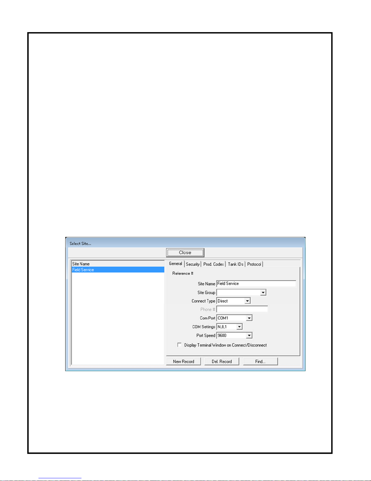
4) Create a Site to connect to.
a. Click on the Sites menu and click Select Sites.
b. Click the New Record button.
Note: If you already have a site configured, simply select the site by clicking on its name
and clicking the Close button. Proceed with Step 5.
c. Enter a Site Name.
d. Verify the settings below Site Name match Figure 3, the default values for the TMS.
Note: COM Port must be set according to your computers hardware settings.
e. Click the Close button.
Figure 3 – TMSComm Direct Connect Site Default Settings
TMS Quick Start-up Guide.docx
Page 8 of 24
November 21, 2017

Quick Start-up Guide TMS Series
5) Connect to the Site by clicking Connect in the Sites menu.
6) Read the configuration from the TMS.
a. Click on the Configurations menu.
b. Click on the File menu in the Configurations window and choose Read Configuration From
Connected Device.
7) Click on the Tanks tab and select the desired Tank Channel.
8) Click on the Probe button.
9) Verify the Probe Information (Calibration Factor, Type, and Length) from the worksheet on Page
2 matches the data shown in TMSComm. If this is correct, proceed to the next step. If this is not
correct, make the appropriate changes, close the Probe window, and proceed to Step 13. Return
to Step 7 to begin the calibration process.
10) Enter the Height Float Offset (HO) information from the worksheet on Page 7 as shown in
Figure 4 for both the Product and Water floats.
11) Click the close button.
12) If there is more than one tank enabled, click on the next enabled tank tab and return to Step 8.
13) Click on the File menu and select the Write configuration to Connected Device option.
Figure 4 - TMSComm Probe Configuration Window
TMS Quick Start-up Guide.docx
Page 9 of 24
November 21, 2017

Quick Start-up Guide TMS Series
Programming Float Height Offsets using TMS Front Panel
Refer to the Figure 5 below for the relative locations of the buttons. Note that each button has three
labels depending upon your display status. Without entering programming mode, the main labels
printed on the buttons are used. Once in programming mode, a nonflashing display represents
Review Mode where a flashing display represents Edit Mode. Note that this represents the latest front
panel button configuration available. Earlier systems maintained the same labeling system but had
physically different buttons.
REVIEW
EDIT
MODE
STEP GROUP SELECT
TANK
SELECT
TEST
EDIT
DWG NO. 20043 REV. N/C
Figure 5 - TMS Front Panel Keys Layout (TMS3000 colors shown)
1) Enter programming Mode by pressing and holding the TEST button and then pressing the
MODE button at the same time until Log (Log) appears. Release both buttons.
2) Press the EDIT (TEST) button repeatedly until Config (Config) appears flashing.
3) Press the ► (MODE) button one time. Header (Header) appears.
4) Press the EDIT (TEST) button repeatedly until Probe (Probe) appears flashing.
5) Press the ► (MODE) button one time. The value for Probe CF for Tank Channel 1 is displayed.
6) Press the GROUP SELECT (TANK SELECT) button until the desired Tank Channel number is
displayed over the TANK ID label on the display.
7) Press and hold the STEP (MODE) button until it beeps ONE TIME and immediately release the
button. Repeat this twice more and Prod HO (Prod HO) will appear briefly then the current value
for the Product Float Height Offset will appear. Note that this number will start with a + (+) or a (-) sign indicating a positive or negative number.
TMS Quick Start-up Guide.docx
Page 10 of 24 November 21, 2017

Quick Start-up Guide TMS Series
8) Press the EDIT ENABLE/THEFT ALARM ACKNOWLEDGE button on the inside of the front door
up one time. This will NOT cause the display to change but will authorize you to make
programming changes to the TMS for the duration of the programming session.
PUSH UP AND
RELEASE
EDIT EN ABLE/
THEFT ALARM
ACKNOW LEDGE
EDIT ENABLE/
THEFT ALARM
ACKNOWLEDGE
DWG NO. 20045 RE V. N/C
Figure 6 - Edit Enable Button
9) Press the EDIT (TEST) button one time and the first digit (cursor) will start flashing. This digit
indicates a positive or negative number. Use the ▼ (GROUP SELECT) and/or ▲ (TEST) buttons
to change the value of what’s flashing. Use the ► (MODE) button to move the cursor to the right.
Once the last digit is flashing the correct value, enter by pressing the ► (MODE) button. It will
stop flashing and show you the current value for the Product Float Height Offset.
10) Press and hold the STEP (MODE) button until it beeps ONE TIME and immediately release the
button. h2o HO (H
O HO) will appear briefly then the current value for the Water Float Height
2
Offset will appear. Note that this number will start with a + (+) or a - (-) sign indicating a positive
or negative number.
11) Press the EDIT (TEST) button one time and the first digit (cursor) will start flashing. This digit
indicates a positive or negative number. Use the ▼ (GROUP SELECT) and/or ▲ (TEST) buttons
to change the value of what’s flashing. Use the ► (MODE) button to move the cursor to the right.
Once the last digit is flashing the correct value, enter by pressing the ► (MODE) button. It will
stop flashing and show you the current value for the Water Float Height Offset.
12) If there is more than one tank enabled, go to Step 6 to calibrate the next tank.
13) Press and hold the STEP (MODE) button until it beeps TWO TIMES and immediately release the
button. Return (Return) appears.
14) Press the EDIT (TEST) button two times. Probe (Probe) will appear flashing on the display.
15) Press the GROUP SELECT (TANK SELECT) button until Return (Return) appears flashing.
16) Press the ► (MODE) button one time. Config (Config) appears.
17) Press the EDIT (TEST) button until Return (Return) appears flashing.
18) Press the ► (MODE) button one time. The system returns to normal operating mode.
TMS Quick Start-up Guide.docx
Page 11 of 24 November 21, 2017

Quick Start-up Guide TMS Series
TMS Front Panel Navigation Chart
Figure 7A - TMS Front Panel Navigation Chart - Legend
TMS Quick Start-up Guide.docx
Page 12 of 24 November 21, 2017

Quick Start-up Guide TMS Series
Figure 7B - TMS Front Panel Navigation Chart - All menus except Configuration
TMS Quick Start-up Guide.docx
Page 13 of 24 November 21, 2017

Quick Start-up Guide TMS Series
Figure 7C - TMS Front Panel Navigation Chart - Configuration menu only
TMS Quick Start-up Guide.docx
Page 14 of 24 November 21, 2017

Quick Start-up Guide TMS Series
TMS Quick Start-up Guide.docx
Page 15 of 24 November 21, 2017
TMS Wiring Diagrams
Figure 8 - TMS AC Power Wiring
PNEUMERCATOR
Liquid Level Control Systems
Bulletin 172 Rev. A (01/19/07)
Page 1 of 1
IMPORTANT! LC2000 AND TMS SERIES GROUND WIRING INSTRUCTIONS
NOTE:
ALL GROUNDS MUST BE TERMINATED AT THE GND BUSS BAR IN THE SAME SERVICE PANEL AS LC2000
AND/OR T MS POWE R. A G ROUNDING ROD, CO LDWAT E R PIPE OR OTHER CONNECTION SHOULD
NOT BE
USED.
BREAKER 6
BREAK ER 5
BREAK ER 4BREAK ER 3
BREAKER 2
BREAK ER 1
GND BUSS BAR
NEUTRAL
BUSS BAR
LINE 2 BUSS
BAR
LINE 1 BUSS
BAR
PARTIAL VIEW OF A TYPICAL
SERVICE PANEL
NEUT
GND
ISGND
ISGND
HOT
PARTIAL VIEW OF
LC2000/TMS CONSOLE

Quick Start-up Guide TMS Series
TMS Quick Start-up Guide.docx
Page 16 of 24 November 21, 2017
Figure 9 - TMS Probe Wiring
Page 1 of 1
IMPORTANT! PROBE WIRING INSTRUCTIONS - MODELS TMS2000/TMS3000/TMS4000
PNEUMERCATOR
Liquid Level Control Systems
NON-INTRIN SICALLY SAFE WIRI NG
INTRINSICALLY SAFE WIRING
HAZARDOUS AREA
CLASS 1, GROUP S C,D
NON-HAZARDOUS AREA
CONDUIT AND VAPOR SEAL FITTING
(SIZE AND LOCATION TO BE
DETERMINED BY QU ALIFIED INST ALLER)
REDUCER FITTING
(IF NEEDED)
JUNCTION BOX
(PROVIDED BY
INSTALLER)
1/2" NPT OR EQ UIV. CABLE GRIP
REQ'D ONLY ON MP45xS MODEL S
(JUNCTION BOX MOUNTS DIRECTL Y
TO PROBE ON MP46xS MODELS)
WIRE SPLICE SEAL CONNECTOR (BY PCO *)
FOLLOW SUPPLIE D WIRE SPLICE INSTRUCTIONS
BULLETIN 179; KIT P/N 10585-2 (FOR MP46xS)
BULLETIN 181; KIT P/N 10585-2L (FOR MP45xS)
FIELD WIRING CABLE (BY CUSTOMER)
EXAMPLE: BELDEN 8441, AVAILABLE
FROM PCO * AS CW1-0500 (500' SPOOL)
TMS CONSOLE
TYPICAL
TANK
W/ PROBE
G
R
N
RED
B
L
K
FIELD CABLE
Note for all probe models:
Conductor colors may vary
depending on cable manufacturer.
The field cable shield wire must
be connected to the PROBE
SHIELD TERMINAL in the console
I.S. compartment and should be cut
back and left unterminated at the
probe junction box.
W
H
T
B
L
K
GND
STUD
TO
TO
TO
TMS2000 PROBE INPUT WIRING TMS3000/TMS4000 PROBE INPUT WIRING
+V
+V
SIG
GND
SHD
GND
+V
2
1
SHD
BLK
RED
C
H
A
N
N
E
L
1
S
E
N
S
O
R
S
P
R
O
B
E
PROBE 2
SHIELD
GND
+V
SHIELD
GND
+V
SHD
BLK
RED
PROBE 1
TYPICAL WIRING FOR TMS CONSOLES
* "PCO" REFERS TO P NEUMERCATOR COMPANY.
FROM
PROBE
TO CONSOLE
(AS SHOWN ABOVE)
3/4" NPT (TMS2000)
1" NPT (TMS3000/TMS4000)
OR EQUIVALENT
CONDUIT FITTING
WIRING MUST BE DONE IN WATERTIGHT RATED BOX/HOUSING
PROBE MODELS
COVERED BY THIS BUL LETIN
MP461SC
MP461S[A], [V]
MP462S[A], [V]
MP463S[A], [V]
MP450S
MP451S
MP452S
Refer to TMS installation manual for
WARNINGS and CAUTIONS before
proceeding. FAILURE TO COMPLY
MAY RESULT IN PER SONAL INJURY,
PROPERTY LOSS AND EQUIPMENT
DAMAGE.
WARNING
MP45xS
RED
B
L
K
R
E
D
BL
K
TO
TO
MP46xS
Bulletin 199 Rev. B (03/25/16)
!

Quick Start-up Guide TMS Series
IMPORTANT! TMS2000 SENSOR WIRING INSTRUCTIONS
IDENTIFY THE TYPE OF SENSOR(S) TO BE INSTALLED. WIRING MUST BE TERMINATED ON THE
TERMINALS INDICATED BELOW TO ENSURE CORRECT OPERATION.
2-WIRE SENSORS
NOTE: "S" = SIGNAL AND IS CONSECUTIVELY NUMBERED "S1"
THROUGH "S8" ON THE TMS2000 CIRCUIT BOARD
+V
W
R
N
G
S
I
I
+V
S
RED
BLK
GRN
BLK
3-WIRE SENSORS
HS100-ND
LS600
NOTE : CONDUCTOR COLOR PAIR PER
SW ITC H POIN T. REFER TO THE TAG
ATTACHED TO THE SENSO R.
M
O
LS600 LD / LS610
RSU801
D
E
L
RSU800
(NON-DISCRIMINATING)
NOTE: "S" = SIGNAL AND IS CONSECUTIVELY NUMBERED "S1"
THROUGH "S8" ON THE TMS2000 CIRCUIT BOARD
+V
S
RED
WHT OR GRN
BLK
+V
W
R
S
I
I
+V
S
RED
BLK
WHT OR GRN
N
G
+V
S
GRN
RED
*
+V
S
BLK
ES825-100 SERIES
ES825-200 SERIES
HS100D
RSU800
(DISCRIMINATING)
* RED IS COMMON GROUND WIRE
M
O
D
E
L
Bulletin 173 Rev. A (11/01/07)
TMS Quick Start-up Guide.docx
Questions? Contact Technical Support at (800) 209-7858
PNEUMERCATOR
Liquid Level Control Systems
Figure 10 - TMS2000 Sensor Wiring
Page 17 of 24 November 21, 2017
Page 1 of 1

Quick Start-up Guide TMS Series
IMPORTANT! TMS3000/TMS4000 SENSOR WIRING INSTRUCTIONS
IDENTIFY THE TYPE OF SENSOR(S) TO BE INSTALLED. WIRING MUST BE TERMINATED ON THE
TERMINALS INDICATED BELOW TO ENSURE CORRECT OPERATION.
SEE PAGE 2 FOR TMS3000 SENSOR NUMBERING SEQUENCE
2-WIRE SENSORS
MODEL
HS100D
FIELD CABLE C ONDUCTOR COLORS SHO WN.
(NON-DISCRIMINATING)
HS100ND
LS600
FIELD CABLE C ONDUCTOR COLORS SHO WN.
NOTE: LS600 SUPPLIED WITH
CONDUCTOR CO LOR PAIR PER
SWITCH POINT. REFER TO THE
TAG ATTACHED TO THE SENSOR.
LS600LD / LS610
RSU800
FIELD CABLE C ONDUCTOR COLORS SHO WN.
(NON-DISCRIMINATING)
RSU801
4-PROBE/8-SENSOR
CARD WIRING
3-WIRE SENSORS
BLK
RED
16-SENSOR
CARD WIRING
GND
SIG
+V
RED
BLK
+V
SIG
4-PROBE/8-SENSOR
CARD WIRING
MODEL
ES825-100 SERIES
ES825-200 SERIES
"W" = WHITE; "G" = GREEN
BLK
W OR G
RED
BLK
HS100D
FIELD CABLE CO NDUCTOR COLORS SHOWN.
(DISCRIMINATING)
"W" = WHITE; "G" = GREEN
RED
W OR G
RED
RSU800
(DISCRIMINATING)
* RED IS COMMON GROUND WIRE
GRN
BLK
NOTE THE REVERSE ORDERING OF SENSOR INPUT NAMES
Questions? Contact Technical Support at (800) 209-7858
16-SENSOR
CARD WIRING
GND
SIG
+V
GND
SIG
+V
+V
SIG
GND
*
GND
SIG
+V
+V
SIG
GND
RED
W OR G
BLK
RED
BLK
W OR G
GRN
RED
BLK
+V
SIG
+V
SIG
+V
SIG
+V
SIG
*
+V
SIG
Bulletin 174 Rev. B (12/07/15)
Figure 11A - TMS3000 Sensor Wiring
TMS Quick Start-up Guide.docx
PNEUMERCATOR
Liquid Level Control Systems
Page 1 of 2
Page 18 of 24 November 21, 2017

Quick Start-up Guide TMS Series
(3)
4-PROBE/
8-SENSOR
CARDS
(2)
4-PROBE/
8-SENSOR
CARDS
(1)
16-SENSOR
CARD
G
PROBE
C
SENSOR 1
H
1
SENSOR 2
PROBE
C
SENSOR 1
H
2
SENSOR 2
PROBE
C
SENSOR 1
H
3
SENSOR 2
PROBE
C
SENSOR 1
H
4
SENSOR 2
SENSOR 1
SENSOR 2
SENSOR 3
SENSOR 4
SENSOR 5
SENSOR 6
SENSOR 7
SENSOR 8
SENSOR 9
SENSOR 10
SENSOR 11
SENSOR 12
SENSOR 13
SENSOR 14
SENSOR 15
SENSOR 16
M
B
I
R
E
C
H
1
C
H
2
C
H
3
C
H
4
C
H
1
C
H
2
C
H
3
C
H
4
G
N
PROBE
SENSOR 1
SENSOR 2
PROBE
SENSOR 1
SENSOR 2
PROBE
SENSOR 1
SENSOR 2
PROBE
SENSOR 1
SENSOR 2
PROBE
SENSOR 1
SENSOR 2
PROBE
SENSOR 1
SENSOR 2
PROBE
SENSOR 1
SENSOR 2
PROBE
SENSOR 1
SENSOR 2
G
1
P
U
O
R
U
N
1
2
3
4
5
6
7
8
1
2
3
4
5
6
7
8
G
N
I
3
P
U
O
R
17
18
19
20
21
22
23
24
17
18
19
20
21
22
23
24
25
26
27
28
29
30
31
32
R
E
B
M
U
N
PROBE
C
SENSOR 1
H
1
SENSOR 2
PROBE
C
SENSOR 1
H
2
SENSOR 2
PROBE
C
SENSOR 1
H
3
SENSOR 2
PROBE
C
SENSOR 1
H
4
SENSOR 2
PROBE
C
SENSOR 1
H
1
SENSOR 2
PROBE
C
SENSOR 1
H
2
SENSOR 2
PROBE
C
SENSOR 1
H
3
SENSOR 2
PROBE
C
SENSOR 1
H
4
SENSOR 2
G
2
P
U
O
R
10
11
12
13
14
15
16
10
11
12
13
14
15
16
U
N
9
9
M
G
N
I
R
E
B
SENSOR 1
SENSOR 2
SENSOR 3
(1)
4-PROBE/
8-SENSOR
CARD
(2)
16-SENSOR
CARDS
Bulletin 174 Rev. B (12/07/15)
TMS Quick Start-up Guide.docx
SENSOR 4
SENSOR 5
SENSOR 6
SENSOR 7
SENSOR 8
SENSOR 9
SENSOR 10
SENSOR 11
SENSOR 12
SENSOR 13
SENSOR 14
SENSOR 15
SENSOR 16
10
11
12
13
14
15
16
17
18
19
20
21
22
23
24
9
C
H
1
C
H
2
C
H
3
C
H
4
25
26
27
28
29
30
31
32
33
34
35
36
37
38
39
40
SENSOR 1
SENSOR 2
SENSOR 3
SENSOR 4
SENSOR 5
SENSOR 6
SENSOR 7
SENSOR 8
SENSOR 9
SENSOR 10
SENSOR 11
SENSOR 12
SENSOR 13
SENSOR 14
SENSOR 15
SENSOR 16
Figure 11B - TMS3000 Sensor Wiring
Page 19 of 24 November 21, 2017
PROBE
SENSOR 1
SENSOR 2
PROBE
SENSOR 1
SENSOR 2
PROBE
SENSOR 1
SENSOR 2
PROBE
SENSOR 1
SENSOR 2
1
2
3
4
5
6
7
8
Page 2 of 2

Quick Start-up Guide TMS Series
TMS Quick Start-up Guide.docx
Page 20 of 24 November 21, 2017
Figure 12A - TMS Series to RA200KR Wiring

Quick Start-up Guide TMS Series
TMS Quick Start-up Guide.docx
Page 21 of 24 November 21, 2017
Figure 12B - TMS Series to RA200KR Wiring
WIRING DRAWING - RA200* TO LC2000 & TMS SERIES
50214 Rev. G (07/18/12) Page 2 of 2
FROM RS2 SWITCH
(SEE PAGE 1)
FROM RA200
AUDIBLE/VISUAL
ANNUNCIATOR
(SEE PAGE 1)
BLK JUMPER
CC
CC
CC
CC
CC
CC
CC
10
9
7
8
5
6
3
4
4
3
NO
NO
6
5
NO
NO
8
7
NO
NO
9
NO
10
NO
CC
I
N
P
U
T
S
O
U
T
P
U
T
S
BLK JUMPER
O
U
T
P
U
T
S
I
N
P
U
T
S
BUILT-IN RELAY I/Os
OR
4X4 RELAY I/O CARD
OR
8X8 RELAY I/O CARD
O
U
T
P
U
T
S
I
N
P
U
T
S
SIG
3
SIG
4
SIG
RELAY 6
COM
NC
RELAY 4
NC
RELAY 3
SIG
56
COM
NO
COM
RELAY 5
COM
NO
NC
NO
NC
NO
BLK JUMPER
SIG
SIG
2 1
COM
NC
NO
COM
NC
RELAY 2
RELAY 1
NO
LC2000/TMS2000
WIRING TERMINATION EXAMPLES SHOWN FOR REFERENCE
(SEE NOTES)
O
U
T
P
U
T
S
I
N
P
U
T
S
O
U
T
P
U
T
S
I
N
P
U
T
S
FROM RA200
AUDIBLE/VISUAL
ANNUNCIATOR
(SEE PAGE 1)
BLK JUMPER
4X4 RELAY I/O CARD
OR
8X8 RELAY I/O CARD
FROM RS2 SWITCH
(SEE PAGE 1)
BLK JUMPER
CC
CC1
1
3
2
4
RELAY 1RELAY 2RELAY4 RELAY 3
CC2
CC3
CC4
NO
NO
NC
NC
COM
COM
NO
NC
NO
COM
COM
NC
1
CC
2
CC
3
CC
4
CC
5
CC
6
CC
7
CC
8
NO
1
NO
2
NO
NO
4
3
NO
NO
6
5
NO
NO
8
7
TMS3000
WIRING TERMINATION EXAMPLES SHOWN FOR REFERENCE
(SEE NOTES)
NOTES:
1.
WIRING MAY BE TERMINATED ON ANY TMS RELAY INPUT/OUTPU T .
HOWEVER, IF REQUESTED WITH ORDER, WIRING MUST BE
TERMINATED ON THE SPECIFIED PRE-PROGRAMMED INPUTS/OUTPUTS.
REMINDER : PROGRAMMING STARTS WI TH THE BUILT-IN MAIN BOARD
RELAYS FOR LC2000 AND TMS2000.
2.
DO NOT MODI FY LC2000/TMS ENCLOSUR E . USE DESIGNAT ED CONDUIT
KNOCKOUTS/OPENINGS AS SHOWN IN THE TMS INSTALLATION MANUAL.
3. TOP CONDUIT HO LE ELIMINATED ON RS2 AS SHOWN O N PAGE 1.
HOWEVER, EXISTING STOCK WITH TOP CONDUIT HOLE MAY STILL BE
SUPPLIED. IF AVAILABLE BUT NOT USED, THE TOP CONDUIT HOLE MUST
BE PLUGGED WITH AN APPROPRIATE FITTING AND WATERTIGHT IF
LOCATED OUTDOORS.
SEE NOTE 1
"W" = WHITE
"G" = GREEN
"W" = WHITE
"G" = GREEN
"W" = WHITE
"G" = GREEN
"W" = WHITE
"G" = GREEN
"W" = WHITE; "G" = GREEN
STROBE
HORN
RED
TEST (N.O.)
COND.
COLOR
W OR G
RED
W OR G
3 COND.
CABLE
BLACK
BLACK HORN/ST ROBE COMMON
RESET (N.O.)
SWITCH COMMON
FUNCTION
* "RA200" CAN ALSO BE WRITTEN AS "RA200-1"
"W" = WHITE
"G" = GREEN
Questio ns? Contact Tech nical Suppo rt at (800) 209-7858
W OR G (RESET; N.O.)
BLK (COM)
RED (TEST; N.O .)
BLK (COM)
W OR G (STROBE)
RED (HORN)
W OR G (RESET; N.O.)
BLK (COM)
RED (TEST; N.O .)
BLK (COM)
W OR G (STROBE)
RED (HORN)
CC
NO
1
2
1
NO
NO
NO
2
4
3
W OR G (STROBE)
RED (TEST; N.O .)
BLK (COM)
BLK (COM)
W OR G
(RESET; N.O.)
RED (HORN)
BLK (COM)
W OR G (STROBE)
RED (HORN)
RED (TEST; N.O .)
BLK (COM)
W OR G
(RESET; N.O.)
RED (TEST; N.O .)
BLK (COM)
W OR G
(RESET; N.O.)
RED (HORN)
W OR G (STROBE)
BLK (COM)
I
N
P
U
T
S
O
U
T
P
U
T
S
TMS1000
(4X4 AND 8X8 RELAY CARDS ARE NOT SUPPORTED)
RED (TEST; N.O .)
BLK (COM)
BLK JUMPER
BLK (COM)
W OR G (STROBE)
RED (HORN)
"W" = WHITE
"G" = GREEN
FROM RA200 AUDIBLE/VISUAL
ANNUNCIATOR (SEE PAGE 1)
FROM RS2 SWIT CH
(SEE PAGE 1)
BUILT-IN RELAY I/Os
CC
W OR G (RESET; N.O.)

Quick Start-up Guide TMS Series
TMS Quick Start-up Guide.docx
Page 22 of 24 November 21, 2017
Figure 13A - TMS Series to RA100R Wiring
Page 1 of 2
50256 Rev. E (07/18/12)
WIRING DRAWING - RA100 TO LC2000 & TMS SERIES
W
H
T
(
S
T
R
OB
E
)
B
L
K
R
E
D
(
H
O
R
N
)
W
H
T
W
H
T
B
L
K
B
L
K
(
C
O
M
)
WIRE NUTS
COVER
(BACK VIEW)
1/2" NPT
(TYP.)
JUNCTION BOX ( BY CUSTOMER)
MUST BE WATERTIGHT IF
LOCATED OUTDOORS
(SHOWN ENLARGED F OR CLARITY)
DO NOT USE THE TMS POWER AS THE SOURCE FOR POWERING THE
RA100.
THIS SYSTEM IS NOT INTRINSICALLY SAFE OR EXPLOSION PROOF.
DO NOT INSTALL INS IDE THE HAZARDOUS AREA.
WARNING
!
1
2
3
1 = RED (TEST)
2 = BLACK (COM)
3 = WHT OR GRN (RESET)
SEE NOTE 3
ON PAGE 2
TEST
RESET
RS2
REMOTE SWITCH
COVER
TO CONTACT
CLOSURE INPUTS
TO RELAY
OUTPUTS
TO LC2000/TMS
(SEE PAGE 2)
3-CONDUCTOR 22 AWG CABLE
BELDEN 8443 OR EQUIVALENT
R
E
D
* INSTALL SO THAT THE DRIP HOLES ARE LOCATED ON
THE BOTTOM (SEE OUTLINE DRAWING 10506). IF
NOT SUPPLIED, DRAWING MAY BE DOWNLO ADED
FROM www.pneumerc ator.com
* RA100 REMO TE AUDIBLE/ VISUAL
ANNUNCIATOR
COVER
(FRONT VIE W)
123412341234432
BELL
HI/LO
HORN
SIREN
WOOP
SLOW
TONE
CODE 3
HORN
CODE 3
TIME
MARCH
1
REMOTE AUDIBLE/V ISUAL ANNUNCIATOR
TONE OPTIONS/SW1 SWI TCH POSITIONS
SER. NO.
RA100-115VAC
MODEL NO.
Liquid Level Control Systems
PNEUMERCATOR
NL
AUD
L
STB
N
PNEUMERCA
Liquid Level C ontrol Sys tems
L NO.
115VAC
SER.
TO
REMOTE AUDIB L CIAT OR
1234
RED
BLK
WHT
WHT
BLK
(H)
WHT
(N)
115 VAC
POWER
PNEUMERCATOR
Liquid Level Control Systems
Questions? Co ntact Technical Support at (800) 209-7858
FUNCTION
HORN/STROBE CO MMON
RESET (N.O.)
SWITCH COMMO N
TEST (N.O.)
W OR G
3 COND.
CABLE
COND.
COLOR
BLACK
W OR G
BLACK
RED
RED
STROBE
HORN
"W" = WHITE; "G" = GREEN

Quick Start-up Guide TMS Series
TMS Quick Start-up Guide.docx
Page 23 of 24 November 21, 2017
Figure 13B - TMS Series to RA100R Wiring
Page 2 of 2
50256 Rev. E (07/18/12)
WIRING DRAWING - RA100 TO LC2000 & TMS SERIES
Questions? Co ntact Technical Support at (800) 209-7858
FUNCTION
HORN/STROBE CO MMON
RESET (N.O.)
SWITCH COMMO N
TEST (N.O.)
W OR G
3 COND.
CABLE
COND.
COLOR
BLACK
W OR G
BLACK
RED
RED
STROBE
HORN
"W" = WHITE; "G" = GREEN
FROM RS2 SWITCH
(SEE PAGE 1)
FROM RA100
AUDIBLE/VISUAL
ANNUNCIATOR
(SEE PAGE 1)
BLK JUMPER
CC
CC
CC
CC
CC
CC
CC
10
9
7
8
5
6
3
4
4
3
NO
NO
6
5
NO
NO
8
7
NO
NO
9
NO
10
NO
CC
I
N
P
U
T
S
O
U
T
P
U
T
S
BLK JUMPER
O
U
T
P
U
T
S
I
N
P
U
T
S
BUILT-IN RELAY I/Os
OR
4X4 RELAY I/O CARD
OR
8X8 RELAY I/O CARD
O
U
T
P
U
T
S
I
N
P
U
T
S
SIG
3
SIG
4
SIG
RELAY 6
COM
NC
RELAY 4
NC
RELAY 3
SIG
56
COM
NO
COM
RELAY 5
COM
NO
NC
NO
NC
NO
BLK JUMPER
SIG
SIG
2 1
COM
NC
NO
COM
NC
RELAY 2
RELAY 1
NO
LC2000/TMS2000
WIRING TERMINATION EXAMPLES SHOWN FOR REFERENCE
(SEE NOTES)
O
U
T
P
U
T
S
I
N
P
U
T
S
O
U
T
P
U
T
S
I
N
P
U
T
S
FROM RA100
AUDIBLE/VISUAL
ANNUNCIATOR
(SEE PAGE 1)
BLK JUMPER
4X4 RELAY I/O CARD
OR
8X8 RELAY I/O CARD
FROM RS2 SWITCH
(SEE PAGE 1)
BLK JUMPER
CC
CC1
1
3
2
4
RELAY 1RELAY 2RELAY4 RELAY 3
CC2
CC3
CC4
NO
NO
NC
NC
COM
COM
NO
NC
NO
COM
COM
NC
1
CC
2
CC
3
CC
4
CC
5
CC
6
CC
7
CC
8
NO
1
NO
2
NO
NO
4
3
NO
NO
6
5
NO
NO
8
7
TMS3000
WIRING TERM INATION EXAMPLES SHOW N FOR REFERENCE
(SEE NOTES)
NOTES:
1.
WIRING MAY BE TERMINATED ON ANY TMS RELAY INPUT/OUTPU T.
HOWEVER, IF RE QUESTED WITH ORDER, W IRING MUST BE
TERMINATED ON THE SPECIFIED PRE-PROGRAMMED INPUTS/OUTPUTS.
REMINDER : PROGRAMMING STARTS WITH THE BUILT-IN MAIN BOARD
RELAYS FOR LC2000 AND TMS2000.
2.
DO NOT MODIF Y LC2000/TMS ENCLOSUR E . USE DESIGNATED CONDUIT
KNOCKOUTS/OPENINGS AS SHOWN IN THE TMS INSTALLATION MANUAL.
3. TOP CONDUIT HOLE ELIMINATED ON RS2 AS SHOWN ON PAGE 1.
HOWEVER, EXIST ING STOCK WITH TOP CONDUIT HOLE MAY STILL BE
SUPPLIED. IF AVAILABLE BUT NOT USED, THE TOP CONDUIT HOLE MUST
BE PLUGGED WITH AN APPROPRIATE FITTING AND WATERTIGHT IF
LOCATED OUTDOORS.
SEE NOTE 1
"W" = WHITE
"G" = GREEN
"W" = WHITE
"G" = GREEN
"W" = WHITE
"G" = GREEN
"W" = WHITE
"G" = GREEN
"W" = WHITE
"G" = GREEN
W OR G (RESET; N.O. )
BLK (COM)
RED (TEST; N.O .)
BLK (COM)
W OR G (STROBE)
RED (HORN)
W OR G (RESET; N.O.)
BLK (COM)
RED (TEST; N.O .)
BLK (COM)
W OR G (STROBE)
RED (HORN)
CC
NO
1
2
1
NO
2
NO
NO
4
3
W OR G (STROBE)
RED (TEST; N.O .)
BLK (COM)
BLK (COM)
W OR G
(RESET; N.O.)
RED (HORN)
BLK (COM)
W OR G (STROBE)
RED (HORN)
RED (TEST; N.O .)
BLK (COM)
W OR G
(RESET; N.O.)
RED (TEST; N.O .)
BLK (COM)
W OR G
(RESET; N.O.)
RED (HORN)
W OR G (STROBE)
BLK (COM)
I
N
P
U
T
S
O
U
T
P
U
T
S
TMS1000
(4X4 AND 8X8 RELAY CARDS ARE NOT SUPPORTED)
RED (TEST; N.O .)
BLK (COM)
BLK JUMPER
BLK (COM)
W OR G (STROBE)
RED (HORN)
"W" = WHITE
"G" = GREEN
FROM RA100 AUDIBLE/VISUAL
ANNUNCIATOR (SEE PAGE 1)
FROM RS2 SWIT CH
(SEE PAGE 1)
BUILT-IN RELAY I/Os
CC
W OR G (RESET; N.O.)

Quick Start-up Guide TMS Series
r
r
RA100R/RA200KR Remote Alarm Programming
Note: For wiring, refer to: Figure 12 for RA200KR.
Figure 13 for RA100R
The following wiring scenario is being provided as a guideline only. The advantage to wiring
the CC Inputs as illustrated is to use the Reset switch in combination with the Test switch. The relays
can be wired in any combination. This is the way your system will be preprogrammed if supplied with
an RA100/RA200 alarm.
Programming:
1. Sets the tank conditions that must occur to activate the relays. Factory default conditions shown
below activate for SP1 (Above 95% volume) and SP2 (Above 90% volume).
Front Panel TMS Communicator
Config Rely Tank Configuration Relays Tank Triggers
Relays Relays
Leak Trig no.no.no Leak Trigger None - None - None
SP1 Trig 01.02.no Set Point #1 Trigger Relay #1 - Relay #2 - None
SP2 Trig 01.02.no Set Point #2 Trigger Relay #1 - Relay #2 - None
SP3 Trig no.no.no Set Point #3 Trigger None - None - None
H2O Trig no.no.no Water Trigger None - None – None
2. Chooses the CC Inputs (wired to RS2) that the relays will react to.
Front Panel TMS Communicator
Config Rely cc Configuration Relays Non-Hazardous Contact Closure Inputs
cc Trig Relays CC Trigger Relay Selects
1 02.no.no #1 Relay #2 – None – None
2 01.02.no #2 Relay #1 – Relay #2 – None
3. Controls the behavior of a relay.
Front Panel
Relay Normally FP Ack Delay Latch En
1 Off No None No
2 Off Yes None No
Relay Normal Contact State Allow Front Panel Acknowledgements Delayed Shutoff Latch Enable
#1 Off
#2 Off
Configuration Relays Relay Mode
4. Controls the behavior of a Contact Closure Input. Note: Only settings used for supporting the RS2 are
listed below. Do not change the factory default values for other unlisted settings.
CC Input cc Enable Normally
1 Ack Open
2 Relay Open
CC Input Contact Closure Enable Normally
#1 Acknowledge Open
TMS Quick Start-up Guide.docx
#2 Relay Open
Configuration Contact Closure Inputs Non-Hazardous Contact Closure Inputs
Config Rely Mode
TMS Communicato
None
None
Front Panel
Config cc Input
TMS Communicato
Page 24 of 24 November 21, 2017
Contact Closure 1 Reset
Contact Closure 2 Test
Relay 1 Strobe
Relay 2 Horn
 Loading...