

Page 1
0088
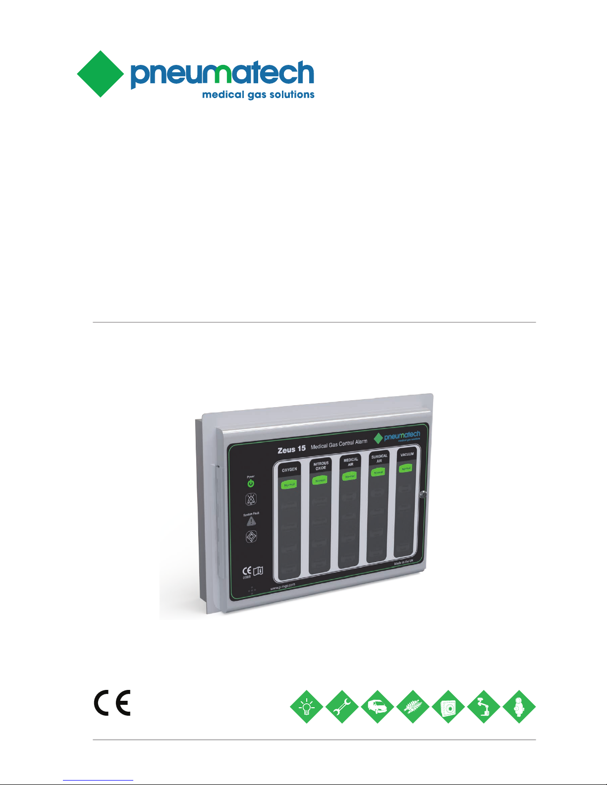
Zeus 15 Central Alarm
Zeus Medical Gas Alarm Systems
Installation, Operation and Maintenance Manual
Page 2

Zeus Central 15 Alarm Page 2
Installation, Operation and Maintenance Manual
Published by Pneumatech Medical Gas Solutions
All possible care has been taken in the preparation of this publication, but Pneumatech Medical Gas Solutions accepts no liability for any inaccuracies that may be found.
Pneumatech Medical Gas Solutions reserves the right to make changes without notice both to this publication
and to the product which it describes.
Copyright © 2015 Atlas Copco All rights reserved.
No part of this publication may be reproduced, transmitted, transcribed, or stored in a retrieval system or
translated into any human or computer language in any form or by any means without the prior permission of
Pneumatech Medical Gas Solutions.
Important
Personnel must make themselves familiar with the contents of this manual and the function of the unit before
installing, operating or maintaining any Zeus 15 medical gas central alarm .
Information contained in this manual is correct at the date of publication. The policy of Pneumatech Medical
Gas Solutions is one of continuous product improvement. Pneumatech Medical Gas Solutions reserves the
right to make changes that may affect instructions in this manual without prior notice.
For any enquiry regarding the servicing or repair of this device, contact the nearest accredited Pneumatech
Medical Gas Solutions agent, or communicate directly with:
Pneumatech Medical Gas Solutions
Unit 18 Nuffield Centrum
Nuffield Way
Abingdon
Oxfordshire
OX14 1RL
UK
http://www.p-mgs.com
Sales Spares Service
Tel: 44 (0) 1235 463010 Tel: 44 (0) 1235 463053 Tel: 44 (0) 1235 463051
Fax: 44 (0) 1235 463011 Fax: 44 (0) 1235 463011 Fax: 44 (0) 1235 463011
[email protected] [email protected] [email protected]
Any complaints about the products or services provided by Pneumatech Medical Gas Solutions, please give
as much of the following information as possible:
Product Part Number
Lot/ Batch Number
Approximate date of purchase
Apparent fault.
Complaints
T: 44 (0) 1235 463010
F: 44 (0) 1235 463011
[email protected]
Page 3

Installation, Operation and Maintenance Manual
Zeus Central 15 Alarm Page 3
Table of Contents
0. SAFETY, STORAGE AND HANDLING 4
0.1 Symbols 4
0.2 Environmental Transport and Storage Conditions &
Operating Conditions 4
1. DESCRIPTION AND OPERATION 5
1.1 Introduction 5
1.2 Standards 6
1.3 Alarm Panels 6
1.4 Visual displays 6
1.5 Test and Mute switches 7
1.6 Audible warning 7
1.7 Printed circuit boards 7
1.8 Alarm contact line fault 10
1.9 Remote audible warning devices 10
1.10 Zeus 15 Relay interface panel 10
1.11 Operation of the alarm system 10
2. INSTALLATION 14
2.1 Installation of a first fix panel 14
2.2 Installation of a Second Fix Assembly 15
3.0 Programming of the alarm system 20
4. COMMISSIONING 23
4.1 Introduction 23
4.2 Functional testing 23
4.3 Basic Checks 23
4.4 Check alarm conditions 23
4.5 Check the audible warning 23
4.6 Check the Remote Audible 23
4.7 Checking the Relay Interface panel 23
4.8 Checking the SYSTEM ALARM indication 23
4.9 Check Central Acknowledge function 24
4.10 Setting the alarm system 24
5. OPERATING INSTRUCTIONS 24
5.1 General operation 24
5.2 System Alarm light 24
5.3 Test switch operation 24
5.4 Mute switch operation 24
6. MAINTENANCE 24
6.1 Introduction 24
6.2 Tools and equipment 24
6.3 Customer recommended maintenance 24
6.4 Weekly inspection 27
6.5 Annual Inspection 27
6.6 Alarm Component Replacement 27
7. FAULT DIAGNOSIS 27
7.1 Introduction 27
8. RECOMMENDED SPARES 29
8.1 Spares scheduling 29
Page 4
Zeus Central 15 Alarm Page 4
Installation, Operation and Maintenance Manual
Alternating current
Static sensitive components
Do not dispose of in general waste
0.2 Environmental Transport and Storage Conditions & Operating Conditions
Min ambient temperature - 0 degrees Celsius
Max ambient temperature - 50 degrees Celsius
Min relative humidity (non-condensing) - 10%
Max relative humidity (non-condensing) - 95%
Atmospheric pressure range - 70-110 kPa
0.3 Cleaning
The alarm cover and fascia should be wiped over with a
damp cloth frequently to remove any dust or foreign substances.
0.4 Environmental Protection
Discard the unit and/or components in line with WEEE
regulations, or other local applicable regulations.
0.5 Electromagnetic Interference
Ensure any input and data cables are physically separated from other mains and data cables.
0.6 Electrical Details
WARNING... It is necessary to check the integrity of the
power source for safety at regular intervals. These checks
should be carried out annually and replacement power
supplies used is necessary.
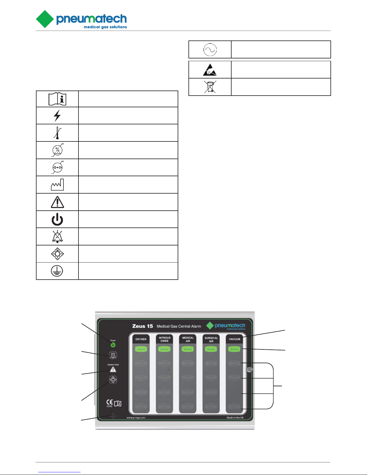
Audible Warning
Test Switch
System Alarm LED
Gas ID Row
Power On LED
Mute Switch
Normal LED
Warning Fault
LED Rows
FIGURE 1 .1- Zeus 15 DISPLAY, SHOWN IN NORMAL RUNNING
0. SAFETY, STORAGE AND HANDLING
0.1 Symbols
The following symbols apply to this product and are used
in these instructions and on the product in question. The
meanings of these symbols are as specified below: -
Read instructions
Warning - dangerous voltage
Ambient temperature range
Ambient humidity range
Ambient pressure range
Date of manufacture
Caution - system alarm
Power on
Mute switch
Test lights
Protective earth
Page 5
Installation, Operation and Maintenance Manual
Zeus Central 15 Alarm Page 5
Power source
Mains operated using 115V 60Hz or 230V 50Hz, alternating current, from an essential circuit. Please see labelling
inside unit for correct voltage.
Current requirements
3.0 amps
Type of protection against electric shock
Class 1 (Mains supplied equipment using a protected
earth)
Mode of operation
Continuous (equipment may be left switched on indefinitely)
Degree of protection against ingress of liquids
IPX32
Degree of mobility
Permanently installed (This unit is electrically connected
by permanent means)
Degree of protection
Type B (no Applied Part or with and Applied Part not designed to meet F type (floating) requirements)
Degree of protection against flammable anaesthetic mixtures
Not protected (not suitable for use with flammable gases)
Rechargeable Battery
The rechargeable battery (ref. 6000157) should be replaced every 5 years.
1. DESCRIPTION AND OPERATION
1.1 Introduction
The Pneumatech MGS Zeus 15 medical gas central
alarm system is designed to provide full monitoring of a
complete medical gas installation. Zeus 15 alarm systems
consist of source panels connected to supply equipment
located in plant rooms, and repeater panels in locations
as specified by the customer for constant monitoring.
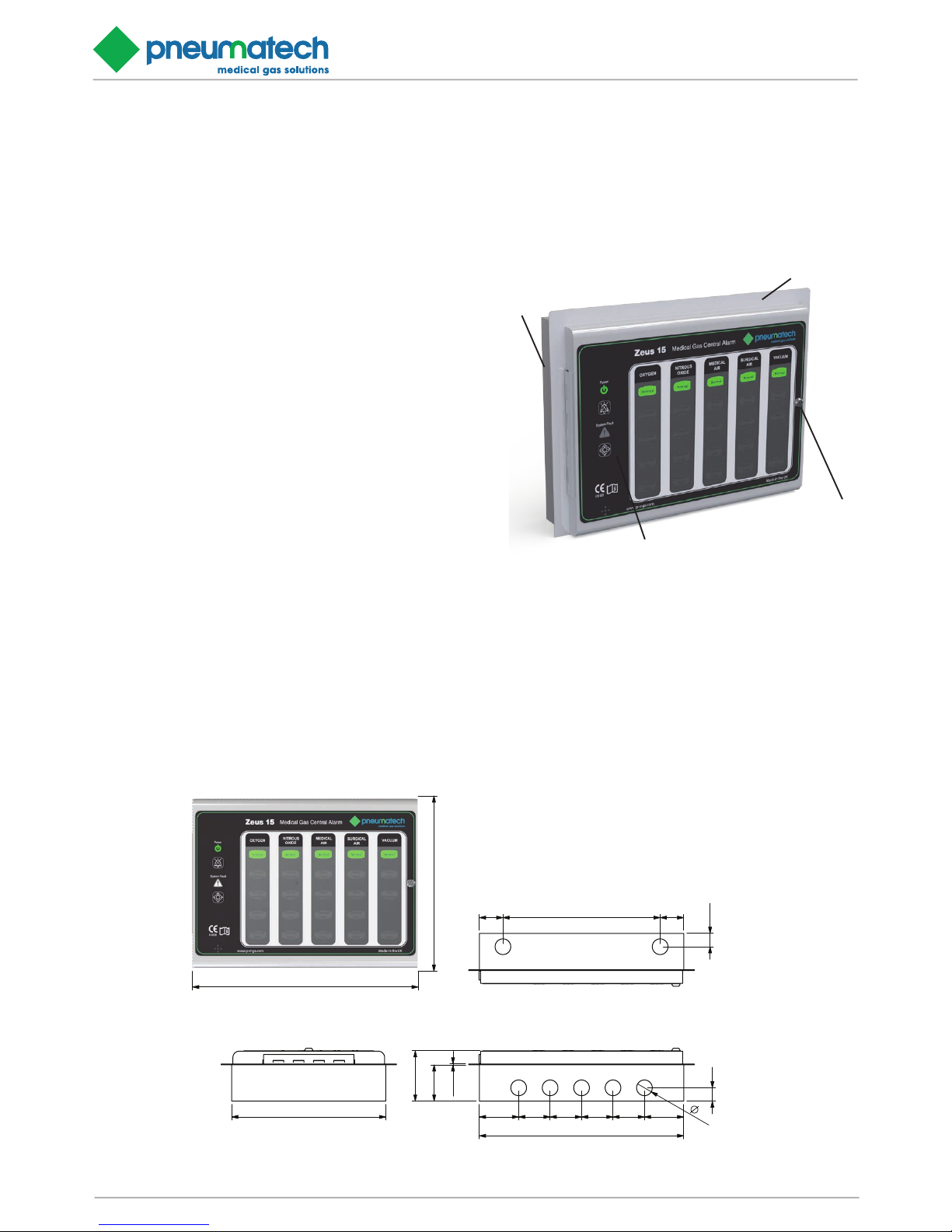
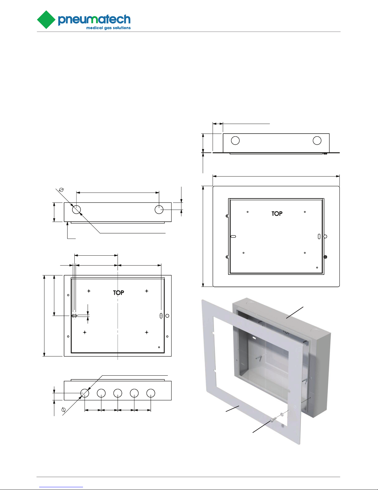
FIGURE 1.2 - Zeus 15 ASSEMBLY
First Fix
(Back Box)
Bezel
(Oponal)
Alarm Panel
Security Fastener
223
287
VIEW FROM FRONT
64
46
1.20
50 40 40 40 40
260
50
20
17
VIEW FROM BOTTOM
196
VIEW FROM SIDE
30 200 30
17
VIEW FROM TOP
FIGURE 1.3 - Zeus 15 DIMENSIONAL DETAILS
Medical gas supply conditions are transmitted throughout
the alarm system by means of an advanced data transmission circuit.
The Zeus 15 can be programmed by the use of switches to
provide a fully flexible alarm system. Allowing the panels
to be adapted to suit any hospital’s medical gas monitoring requirements (see section 3 for programming details).
Page 6
Zeus Central 15 Alarm Page 6
Installation, Operation and Maintenance Manual
An individual Zeus 15 panel has 5 columns consisting of
‘normal’ and 4 ‘fault’ conditions. These columns can be
setup to monitor either up to 5 medical gas source equipment, or up to 20 individual point alarms, or a combination
of the 2.
One Zeus 15 alarm panel is designated the master panel
for control purposes. Any number of panels may be programmed as a ‘central acknowledge panel’ and cause all
flashing displays on the system to change to steady when
the MUTE switch on the central acknowledge panel is operated. Each Zeus 15 alarm panel connects directly with
the mains electrical power supply and alarm panels are
available for use with AC supplies of either 115V±10%,
60Hz or 230V±10%, 50Hz. Electrical power supplies
should be from an essential circuit and fused at 3 Amps.
Each Zeus 15 alarm panel incorporates flashing alarm displays, a POWER ON indication, a SYSTEM ALARM indication, MUTE and TEST switches and an audible warning
programmed to operate depending upon the alarm condition displayed (see figure 1.1 for display image). Alarm
panels are interconnected by data transmission cable.
Relay interface units are available to input conditions into
existing alarm systems or building management systems.
1.2 Standards
The Pneumatech MGS Zeus 15 medical gas central alarm
system is specifically designed and manufactured to fully
satisfy the National Health Service – Model Engineering Specification C11, and is therefore ideal for HTM0201/HTM2022 applications. Pneumatech MGS Zeus 15
medical gas alarms are suitable for both United Kingdom
and International markets, and are fully tested prior to
dispatch and packaged to provide maximum protection
during transit. Alarm panel printed circuit boards are designed to operate in an ambient temperature of between
0°c and +50°c. Component assemblies must be stored in
their packaging in dry conditions and storage temperatures must be between 0°c and +50°c.
Alarm panel enclosures provide protection to IP32 (BS
EN 60529) and are electrically bonded to earth to provide
safe installation.
1.3 Alarm Panels
Each alarm panel consists of a first and second fix assembly, and are suitable for use with either surface or concealed installations. A bezel plate is provided for use with
concealed installations and is fitted to the first fix assembly to give a neat appearance by covering the plaster joint.
The front cover of the enclosure is hinged and retained
by a special fastener which prevents unauthorised access
(see figure 1.2).
The assembly contains two printed circuit boards and provides a gas service display through windows in the front
cover. The front cover has a flush dark finish polyester fas-
cia to highlight the displays. Five columns of display windows indicate ‘Normal’ and ‘4 alarm conditions’, for each
gas service monitored.
Displays are illuminated by coloured LED block indicators
and have captions to indicate the gas service, ‘Normal’
and ‘Alarm’ conditions. The alarm panel also incorporates
a green LED to indicate that the electrical power supply
is ON, and a red LED to indicate an alarm system fault
(SYSTEM ALARM). A MUTE switch is provided to mute
the audible warning and a TEST switch is provided to test
the internal circuits, LED’s and audible warning within the
panel. Overall dimensions are detailed at Table 1.1 & Figure 1.3.
Gas service legends are printed on acetate strips, which
slide into the alarm panel front cover through the uppermost internal slots. The correct combination of gas service legends must be fitted to satisfy the requirements
of a particular location with blank strips fitted to display
columns not used. Normal C11/HTM02-01/HTM2022 legends are available as standard any special legends, point
alarm legends etc. must be ordered as specials.
TABLE 1.1: Zeus 15 – DIMENSIONS
Alarm Panel Bezel
Height(mm)
196.0 246.0
Length(mm)
260.0 310.0
Depth(mm)
61.2 18 swg
Chase depth(mm)
45.0 -
1.4 Visual displays
Coloured LED’s fitted to the light display PCB provide the
following visual displays:
1.4.1 Power On indication (see figure 1.1):
The Power On indication is displayed by a green LED
which is extinguished in the event of a power failure.
1.4.2 System Alarm indication (see figure 1.1):
The System Alarm indication is displayed by a red LED
which is normally extinguished. This LED flashes to draw
attention to any of the following failures:-
Alarm contact line fault
Electrical power supply failure
Internal alarm failure
Data transmission failure
1.4.3 Normal gas service indication (see figure 1.1):
The Normal indication is displayed by a steady illuminated
green LED which is extinguished in the event of an alarm
condition.
1.4.4 Alarm conditions (see figure 1.1):
Each alarm condition is indicated by flashing LED’s (yel-
Page 7

Installation, Operation and Maintenance Manual
Zeus Central 15 Alarm Page 7
The audible tone consists of a modulation between two
tones (F1 and F2). F1 = 440Hz and F2 = 880Hz. The
modulation rate is 4 Hz in accordance with HTM02-01/
HTM2022 and C11 (see figure 1.4). Audible warning may
be muted for specific alarm conditions during prolonged
maintenance of plant or pipeline shut-down by operating
the MAINTENANCE MUTE switch inside the alarm panel
(see figure 1.6).
Operation of the MUTE switch on a central acknowledge
panel signifies that action is in hand to identify and rectify the fault which produced the alarm condition. This information is transmitted to all repeater panels displaying
the gas service and the flashing visual display becomes
steady, on all the respective display alarm panels, and the
audible alarm is muted. This feature will automatically reset when the channel returns to normal, if a further alarm
occurs, or the 15 minute time-out expires.
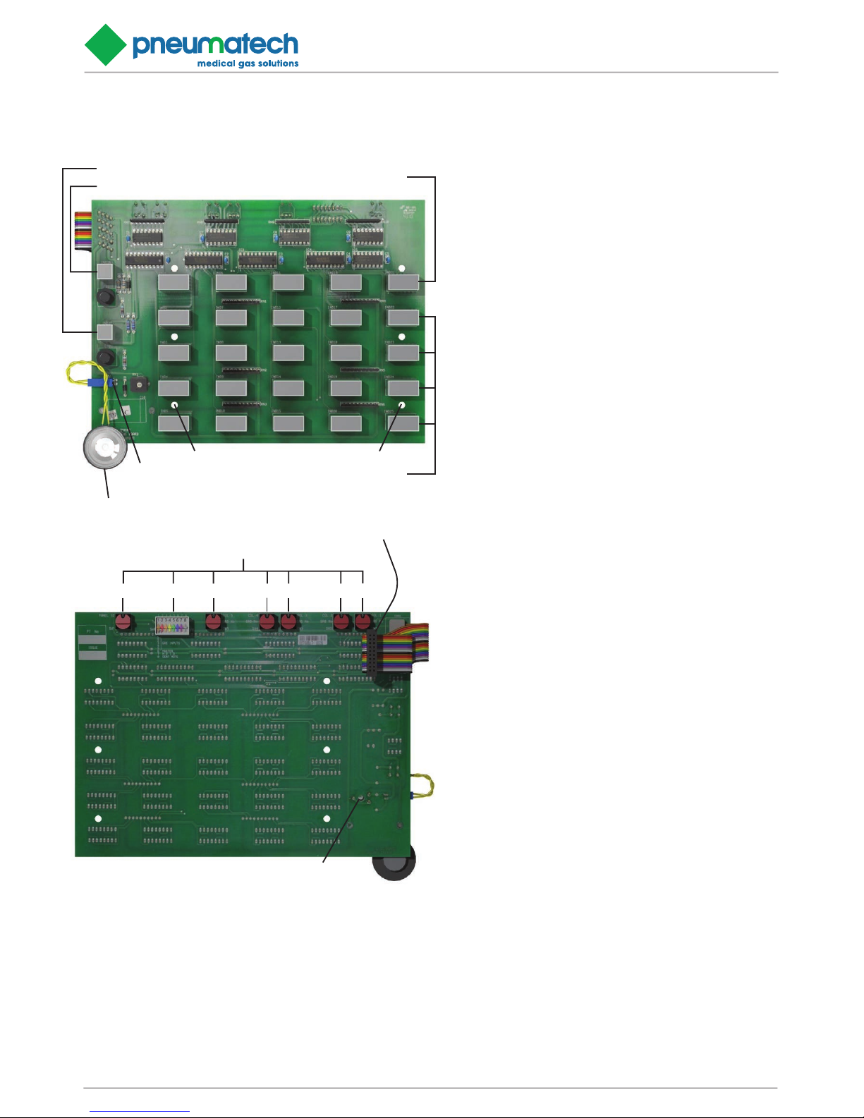
1.7 Printed circuit boards
Two printed circuit boards (PCB’s) are fitted inside a Zeus
15 Medical gas area alarm, i.e. a power supply PCB (see
figure 1.5 & 1.6) and a light display PCB (see figure 1.4).
All components are mounted on these PCB’s which are
interconnected by means of a multi-way ribbon cable and
polarised connector. The Zeus 15 internal electrical installation complies with all relevant British Standard specifications, IET wiring regulations and current UK legislation.
1.7.1 Light display printed circuit board
(see figure 1.4)
The light display PCB is retained inside the alarm panel
front cover with six retaining studs. This PCB contains
5 columns of 5 coloured LED block indicators, a green
POWER ON and red SYSTEM ALARM LED block indicator. Each LED block indicator aligns with display windows
in the front cover and fascia to provide a clear display.
Each gas service indicator contains eight separate long
life LED’s connected in two banks of four, and both the
POWER ON and SYSTEM ALARM LED contains four
separate long life LED’s connected in parallel in two banks
of two. This duplex circuitry provides system reliability and
ensures that illumination continues in the event of either a
single LED or circuit failure. Each LED block indicator is a
plug-in component enabling easy replacement or subsequent updating of the installation.
The ribbon cable is permanently attached to the rear face
of the light display PCB and enables interconnection of
circuits with the power supply PCB. The audible warning
speaker is connected by plug and socket to the light display PCB and locates within the alarm panel front cover
when installed.
The light display PCB incorporates both rotary and DIL
switches to allow easy programming of the alarm panel to
suit all configurations.
low or red) to draw attention to the specific alarm condition. All flashing displays are programmed at sixty flashes
per minute, 0.5 seconds on and 0.5 seconds off in accordance with C11 and HTM02-01/HTM2022.
1.4.5 Display positions
To provide an aesthetic display and maintain consistency
in accordance with recognised and established Medical
gas service sequencing, it is recommended that displays
are positioned in the following sequence on each alarm
panel commencing with the left hand column:-
Medical Oxygen (cryogenic and manifolds)
Nitrous oxide (manifolds)
Oxygen/Nitrous oxide (manifolds)
Medical Air 400 kPa (plant and manifolds)
Medical Air 700 kPa (plant and manifolds)
Medical Vacuum (plant)
AGS (simplex or duplex)
Point alarms (as required)
1.5 Test and Mute switches
(see figure 1)
TEST and MUTE switches require only gentle finger pressure. Operation of the TEST switch initiates the audible
warning and illuminates (flashing) all the displays on the
panel. This simple check proves the integrity of all LED’s
internal alarm circuits and audible warning. Given an
alarm condition, operation of the MUTE switch silences
the audible warning for 15 minutes.
CAUTION:
The TEST and MUTE switches must only be operated
by gentle finger pressure. Operation by the use of instruments, tools or other implements will cause damage to
the switch.
1.6 Audible warning
The audible warning speaker is clipped to the alarm panel
front cover and connected to the light display PCB by plug
and socket (see figure 1.4). The speaker operates simultaneously with any specified alarm conditions or SYSTEM
ALARM indication. The audible warning may be muted by
pressing the MUTE switch (see figure 1.1). If following a
mute condition another alarm condition occurs, the audible warning will operate simultaneously with the indication. Following a mute condition and a continuing alarm
indication, the audible warning will resound after 15 minutes in accordance with HTM02-01/HTM2022 and C11.
When the audible resounds further operation of the MUTE
switch is necessary to cancel the audible. Audible warning
volume may be adjusted by means of a screwdriver slot
in the rear face of the light display PCB (see figure 1.4). If
following an alarm condition no action is taken to MUTE
the audible, the audible warning will automatically switch
off when the alarm condition reverts to NORMAL.
Page 8
Zeus Central 15 Alarm Page 8
Installation, Operation and Maintenance Manual
FIGURE 1.4 - Zeus 15 LIGHT BOARD
AUDIBLE WARNING
SPEAKER CONNECTION
POWER ON LED
SYSTEM ALARM LED
NORMAL CONDITION LED’s
FAULT CONDITION LED’s
RETAINING STUD LOCATIONS x 6
AUDIBLE WARNING SPEAKER
PROGRAMMING SWITCHES (SEE SECTION 1.12)
MULTI-WAY RIBBON TO POWER BOARD
AUDIBLE WARNING VOLUME CONTROL
SW1SW2SW3SW4SW5SW6
SW7
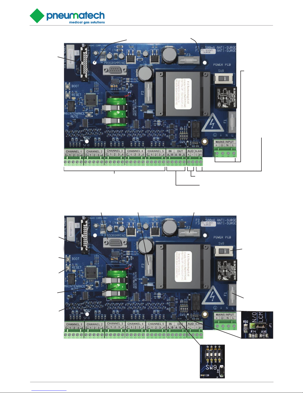
1.7.2 Power supply printed circuit board (see figure 1.5
& 1.6)
The power supply PCB is retained inside the alarm panel
back box with four retaining studs and connects to the
light display PCB multi-way ribbon cable by polarised connectors. The power supply PCB incorporates four mains
terminals connected to matching plug/socket combination
to accept the mains electrical power supply, which should
be from an essential circuit, and enables connection of
flying earth leads which electrically bond the assembly.
The power supply PCB should be set to the appropriate local mains supply voltage, either 115V±10% or
230V±10%. SW8, on the power PCB selects the voltage.
A filter protects the alarm system from possible spikes or
disturbances of the incoming electrical power supply and
an integral transformer provides 15V and 5V supplies to
operate the alarm circuits. Three fuses 20mm x 5mm to
BS4265 protect the power supply circuits. F1 is rated at
500mA for 230V supplies and 1A for 115V supplies, F2 at
1A, and F3 at 500mA.
All mains power supply circuits and components are enclosed, with the exception of the connection terminal. A
warning notice reminds personnel to isolate the electrical
power supply prior to removal and maintenance, and a
small plastic cover prevents accidental contact. In order to
prevent inadvertent cross connection, the mains electrical
power supply plug and socket is not compatible with any
other connection to the PCB.
The power supply printed circuit board incorporates a microprocessor which controls the operation of the alarm
panel. A “MAINTENANCE MUTE” push button ( see figure 1.6) is fitted on the power supply PCB and is accessible with the alarm panel front cover open. With an alarm
condition displayed, operation of this button disables audible reinstatement for any active alarms. This facility is
designed for use when the plant or pipeline is shutoff for a
prolonged period. Should additional alarms occur during
a maintenance mute, the audible will re-sound. On returning the plant or pipeline pressure to NORMAL this feature
automatically resets without further manual intervention.
The power supply PCB incorporates 5 input channels
for connection to their respective inputs. Each channel
(designated CH1 to CH5) incorporates 5 terminals (C –
Common, 1, 2, 3 and 4) which are connected by matching plug/socket combination to accept signals from their
respective inputs.
A relay (complete with line continuity monitoring circuit)
suitable for switching 50V and a maximum of 0.5 Amps
is fitted to the power supply PCB. The relay has volt free,
normally open contacts and two terminals (N/O and C)
enable connection by a matching plug/socket combination to either a Medipoint central alarm system or other
suitable system. The line continuity monitoring circuit can
be de-selected by means of a jumper on JP1 located on
the power supply PCB. The relay is de-energised and contacts open when any of the twenty alarm conditions are
initiated.
Terminals are also provided to enable connection of a remote audible warning device (AUD+ and AUD-). It is recommended that the input and data transmission cables
are installed separate from the mains cable and maximum
Page 9
Installation, Operation and Maintenance Manual
Zeus Central 15 Alarm Page 9
BACKUP BATTERY
CONNECTION
FIGURE 1.6 - Zeus 15 POWER SUPPLY BOARD SWITCH & FUSE LAYOUT, PLUS BACKUP BATTERY
ELV 1A FUSE [F2] ELV 500mA FUSE [F3]
MAINS FUSE
[F2]
500mA (230V)
1A (115V)
VOLTAGE CHANGE
OVER SWITCH
230V OR 115V
OPTION
(SW8)
CONFIGURABLE DIP
SWITCHES FOR DATA
TRANSMISSION
COMMUNICATION PORT
MAINTENANCE
MUTE SWITCH
BOOT
RESET
BACKUP BATTERY
JUMPER JP1
(SEE NOTE)
FIGURE 1.5 - Zeus 15 POWER SUPPLY BOARD CONNECTION LAYOUT AND MOUNTING
RETAINING STUD LOCATIONS x 4
MULTI-WAY
DATA RIBBON
FROM LIGHT
BOARD
INPUTS FOR DISPLAY COLUMNS 1-5
[COMMON] [FAULT CONDITIONS 1-4]
NOTE - FAULT CONDITION 1 COINCIDES WITH THE TOP
FAULT CONDITION LED, WORKING DOWN IN ORDER
DATA TRANSMISSION CONNECTIONS
IN [A] [B], OUT [A] [B] AND [SCREEN]
REMOTE AUDIBLE CONNECTION [+] [-]
OUTPUT RELAY
FOR
TRANSMITTING
SINGLE
EVENT ALARM
[COMMON]
[N/O]
MAIN POWER
CONNECTION
[BONDING
EARTH]
[MAIN EARTH]
[NEUTRAL]
[LIVE]
Page 10

Zeus Central 15 Alarm Page 10
Installation, Operation and Maintenance Manual
cable length between alarm panel and input should not
exceed 100 Metres. Alarm panels accept a mains electrical power supply cable of 2.5 sq mm, and all other terminals accept a maximum cable size of 1.5 sq mm.
1.7.3 Standby battery (See figure 1.6)
The power supply PCB also contains a standby battery,
battery charging and power fail detection circuits. The battery provides power for both the SYSTEM ALARM indication and the audible warning in the event of an electrical
power failure. The battery is fully charged after 72 hours
and provides sufficient power to operate the specific
alarm indications for a minimum of 4 hours. The battery is
expected to have a minimum 5 years life.
1.7.4 LED Status indicators
The power PCB has five LED’s to indicate the following
conditions to help with fault diagnostics:-
LED1 is a “heartbeat” indication, and will normally flash
green. When the power has failed, the LED will be off. If
the software identifies the incorrect board, the LED will be
solid red.
LED2 will blink green when the RS-485 is transmitting
data, off when no activity.
LED3 will blink red when the RS-485 is receiving data, off
when no activity.
LED4 will blink green when the RS-232 is transmitting
data, off when no activity.
LED5 will blink red when the RS-232 is receiving data, off
when no activity.
See section 7. Fault Diagnosis table 17.9.
1.8 Alarm contact line fault
CAUTION:
Only Pneumatech MGS line continuity monitor modules
should be fitted, otherwise the SYSTEM ALARM circuits
could provide spurious indications.
Integrity of the interconnecting wiring and input sensors
are constantly monitored by the SYSTEM ALARM detection circuits. The monitoring circuit is designed to detect
an open or short circuit as well as normal operation of
the pressure sensor. In the event of a line fault the NORMAL LED remains illuminated, the appropriate gas service alarm indicator and SYSTEM ALARM indicator will
illuminate and the audible warning sounds. When a line
continuity fault is detected the flash rate of the affected
circuit LED speeds up to show short circuit or slows to
show open circuit when the TEST switch is operated. This
facility is designed to aid fault diagnosis. Inputs must be
‘normally closed’ volt free contacts.
CAUTION:
As the alarm panel monitors specific resistance values,
only one input sensor (for each specific gas service) may
be connected to an alarm panel. Similarly it is not possible
to connect more than one alarm panel to a single input
sensor.
1.9 Remote audible warning devices
Remote audible warning devices may be fitted in locations
where warnings are necessary and alarm panels are not
fitted. Remote audible warning devices are housed in a
surface mounted enclosure containing a warning buzzer.
The audible warning device is connected by input cable to
the power supply PCB within the alarm panel (alarm terminals AUD+ and AUD-, see figure 1.5). When the alarm
panel audible sounds the remote audible also sounds. A
maximum of four remote audible warning devices can be
fitted to an alarm panel and the cable length should not
exceed 50 metres.
1.10 Zeus 15 Relay interface panel
A dedicated relay interface panel assembly enables the
Zeus 15 medical gas central alarm system to be interconnected to an event recording circuit of a building management system, or other suitable alarm system. The relay
interface unit is housed within a standard alarm panel enclosure and provides a fascia display of both POWER ON
and SYSTEM ALARM. The relay interface panel incorporates a dedicated power supply PCB and a dedicated relay printed circuit board. The power supply PCB provides
no-volt terminals (C, 1, 2, 3, 4) for each channel CH1 to
CH5 to interconnect with a BMS system. The relay printed
circuit board is similar to the standard light display board,
except that the gas service alarm LED’s are replaced by
normally open low voltage relays. With the gas service operating normally, relay contacts are closed providing continuity between terminals C and 1, 2, 3, 4. In the event of
a gas service failure the respective relay contacts open to
break the continuity between terminals C and either 1, 2,
3 or 4. Relays are connected to the BMS system at terminals C, 1, 2, 3 and 4 and are rated at a maximum voltage
of 50V d.c. with a maximum current of 50mA.
For more details see document number 2005202 - Zeus
15 Relay Interface MK2 manual.
1.11 Operation of the alarm system
Each Zeus 15 medical gas alarm panel is connected to
the mains electrical power supply and operates by 15V
and 5V d.c. circuits from it’s integral transformer. Service
fault condition sensors provide the input to initiate both the
visual displays and audible warning. Programming of the
panels is done via switches which can be easily adjusted
on site from within the panel (see programming section
1.12).
Page 11

Installation, Operation and Maintenance Manual
Zeus Central 15 Alarm Page 11
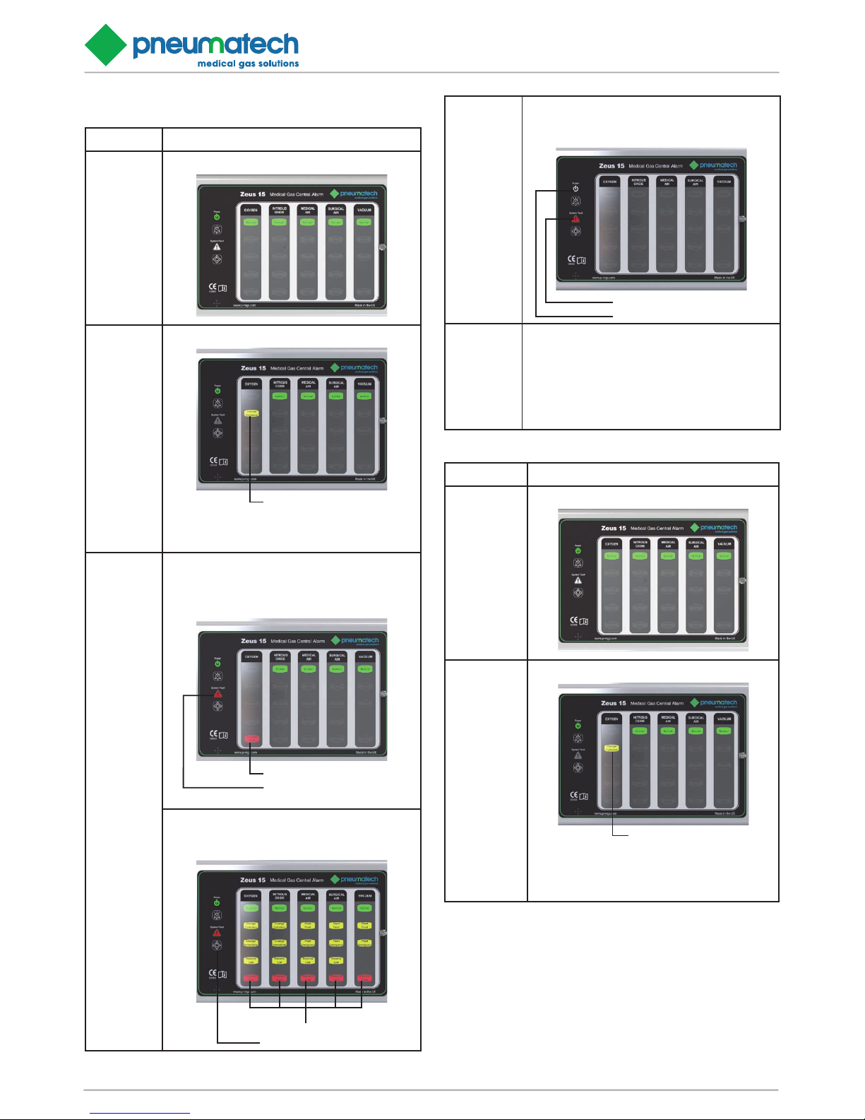
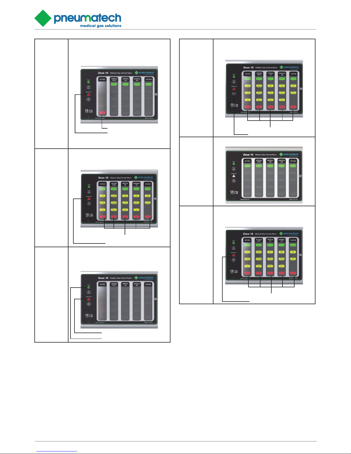
The Zeus 15 medical gas panels use coloured LED’s to
indicate the service conditions (see table 3 & 4). During
normal conditions, the green NORMAL LED is illuminated.
Should a service fault occur, the green (NORMAL) LED is
extinguished and the appropriate service fault condition is
illuminated (flashing) either by a yellow LED for warning
conditions or red LED for emergency conditions, together
with an audible warning. The audible warning continues
until either the MUTE switch is operated or the fault condition returns to NORMAL. If the MUTE facility is operated
and the alarm condition remains, the audible warning will
re-sound after 15 mins and a further MUTE selection will
be required. Should a further alarm condition occur after
the panel has indicated a fault and has been muted, the
audible warning is re-activated.
The relay output (N/O and C) may be interconnected to a
suitable system. The contacts are closed when all gas services are indicating NORMAL. In the event of any alarm
condition, the relay contacts open, breaking the circuit to
the remote system. The relay contacts remain open until
all alarm conditions return to NORMAL condition. There
is also a line continuity monitor integral to the board available across the N/O and C contacts. To select this the
jumper on JP1 is moved to the LCM position, for totally
volt free contacts the jumper is moved to the N/O position
(see figure 1.6).
The green POWER ON LED is normally illuminated and
is extinguished in the event of an electrical power failure.
The red SYSTEM ALARM LED is normally extinguished
and illuminates (flashing) together with an audible warning, in the event of any of the following failures:-
Alarm contact line fault.
Electrical power supply failure.
Internal alarm circuit failure.
Data transmission failure.
When a line continuity fault is detected, the NORMAL
green LED remains illuminated, the respective alarm LED
also illuminates (steady), and the SYSTEM ALARM LED
illuminates (flashing) accompanied by an audible warning.
Operation of the TEST switch illuminates all alarm LED’s
(flashing) and the flashing rate of the respective alarm
LED indicates the type of fault. If the respective alarm LED
flashes at a faster rate, this indicates a short circuit. If the
respective alarm LED flashes at a slower rate, this indicates an open circuit. This facility is designed to aid fault
diagnosis. The Zeus 15 medical gas central alarm system
logic is detailed at Table 3 and 4.
Page 12
Zeus Central 15 Alarm Page 12
Installation, Operation and Maintenance Manual
TABLE 1.2: Zeus 15 ALARM LOGIC – INPUT PANEL
Condion Input Panel - Alarm displays
Normal NORMAL (steady)
Alarm
condion
Alarm (ashing), Audible if required.
Alarm condion
Example shows fault on channel 1, column 1
Warnings condions - Yellow LED’s
Emergency condions - Red LED’s
Line
contact fault
NORMAL (steady)
Alarm condions (steady)
SYSTEM ALARM (ashing)
Audible
Alarm condion
System alarm
Example shows fault on channel 4, column 1
Press TEST Switch, line connuity fault ashes
slower than other LED’s to indicate an open circuit
or faster to indicate a short circuit
Alarm condions
Test switch
Power failure
to input
panel
SYSTEM ALARM (ashing)
Audible (aer 30 seconds)
POWER ON LED exnguished
System alarm
Power on LED
Data
cable break/
failure
between
input and
repeater
panel
All input channels to panel displayed as normal. All
displayed gas services relayed from repeater panel
all alarms
illuminate (ashing)
SYSTEM ALARM
(ashing)
Audible
TABLE 4: Zeus 15 ALARM LOGIC – REPEATER PANEL
Condion Repeater Panel - Alarm displays
Normal NORMAL (steady)
Alarm
condion
Alarm (ashing), Audible if required.
Alarm condion
Example shows fault on channel 1, column 1
from the input panel.
Warnings condions - Yellow LED’s
Emergency condions - Red LED’s
Page 13
Installation, Operation and Maintenance Manual
Zeus Central 15 Alarm Page 13
Line
contact fault
NORMAL (steady)
Alarm condions (steady)
SYSTEM ALARM (ashing)
Audible
Alarm condion
System alarm
Example shows fault on channel 4, column 1
from the input panel.
Press TEST Switch, line connuity fault ashes
slower than other LED’s to indicate an open
circuit or faster to indicate a short circuit
Alarm condions
Test switch
Power failure
to repeater
panel
SYSTEM ALARM (ashing)
Audible (aer 30 seconds)
POWER ON LED exnguished
System alarm
Power on LED
Repeater
panel display
when power
fails to a
connected
input panel
All alarms condions (ashing)
SYSTEM ALARM (ashing)
Audible
Alarm condions
System alarm
Repeater
panel display
when power
fails to a
connected
repeater panel
NORMAL (steady)
Repeater
panel display
when Data
cable from
input panel
breaks/failure
All alarms condions (ashing)
SYSTEM ALARM (ashing)
Audible
Alarm condions
System alarm
Page 14
Zeus Central 15 Alarm Page 14
Installation, Operation and Maintenance Manual
2. INSTALLATION
2.1 Installation of a first fix panel
The alarm panel backbox is suitable for both surface and
concealed installation and is annotated ‘TOP’ inside to ensure correct orientation. With a concealed installation a
chase depth of 45mm is required and a bezel is fitted to
cover the plaster joint. The procedure to install a first fix
alarm panel backbox is as follows: -
2.1.1 Backbox. Locate (see figure 2.1).
Ensure the backbox is the correct way up. Locate the
backbox at the correct position and mark out for securing
screws.
2.1.2 Wall. Fit anchors.
Drill wall and fit anchors in position.
2.1.3 Backbox. Fit (see figure 2.1).
Select cable entry/exit points and remove the desired
knock-out segments from the inside. Fit suitable grommets/cable glands as required by the contract specification. Feed cables into the box leaving 400mm to enable
connection to printed circuit board. Secure back box to
wall with suitable screws.
7 101.50
98
196
5
105
105
200
17
20
46
KNOCKOUT SEGMENTS
BACKBOX SURFACE
40 40 40 40
17
20
KNOCKOUT SEGMENTS
FIGURE 2.1 - BACKBOX DETAILS
WARNING...WITH A CONCEALED INSTALLATION, THE PLASTER
DEPTH MUST BE FLUSH WITH THE BOX SURFACE, LEAVING THE
WATER CHANNEL PROUD OF THE PLASTER.
FIGURE 2.2 - BEZEL DETAIL
310
246 46
25 (ALL ROUND)
1.20
BEZEL
(OPTIONAL)
SECURING SCREW
(M4 x 12 PAN HEAD)
BACK BOX
Page 15
Installation, Operation and Maintenance Manual
Zeus Central 15 Alarm Page 15
WARNING...WITH A CONCEALED INSTALLATION, THE
PLASTER DEPTH MUST BE FLUSH WITH THE BOX
SURFACE, LEAVING THE WATER CHANNEL PROUD
OF THE PLASTER.
2.2 Installation of a Second Fix Assembly
WARNING...ENSURE THAT THE ELECTRICAL POWER
SUPPLY TO THE ALARM IS OFF AND REMAINS ISOLATED UNTIL REQUIRED DURING THE COMMISSIONING
PROCEDURE
2.2.1 Backbox. Check.
Ensure that the inside of the backbox is clean and free
from debris.
Concealed installation. Fit bezel plate (see figure 2.2).
Fit bezel plate to backbox and retain with securing screw
engaged in right hand anchor nut.
2.2.2 Fit Legends as required
(see figures 2.3; 2.4 and table 2.1)
Fit blank and gas/vacuum service legend, through the
slots in the rear of the cover, as required. NB. It is necessary to remove the display PCB to access the slots easily.
To provide an aesthetic display and maintain consistency
in accordance with recognised and established Medical
gas service sequencing, it is recommended that displays
are positioned in the following sequence on each alarm
panel commencing with the left hand column:-
Medical Oxygen (cryogenic and manifolds)
Nitrous oxide (manifolds)
Oxygen/Nitrous oxide (manifolds)
Medical Air 400 kPa (plant and manifolds)
Medical Air 700 kPa (plant and manifolds)
Medical Vacuum (plant)
AGS (simplex or duplex)
Point alarms (as required)
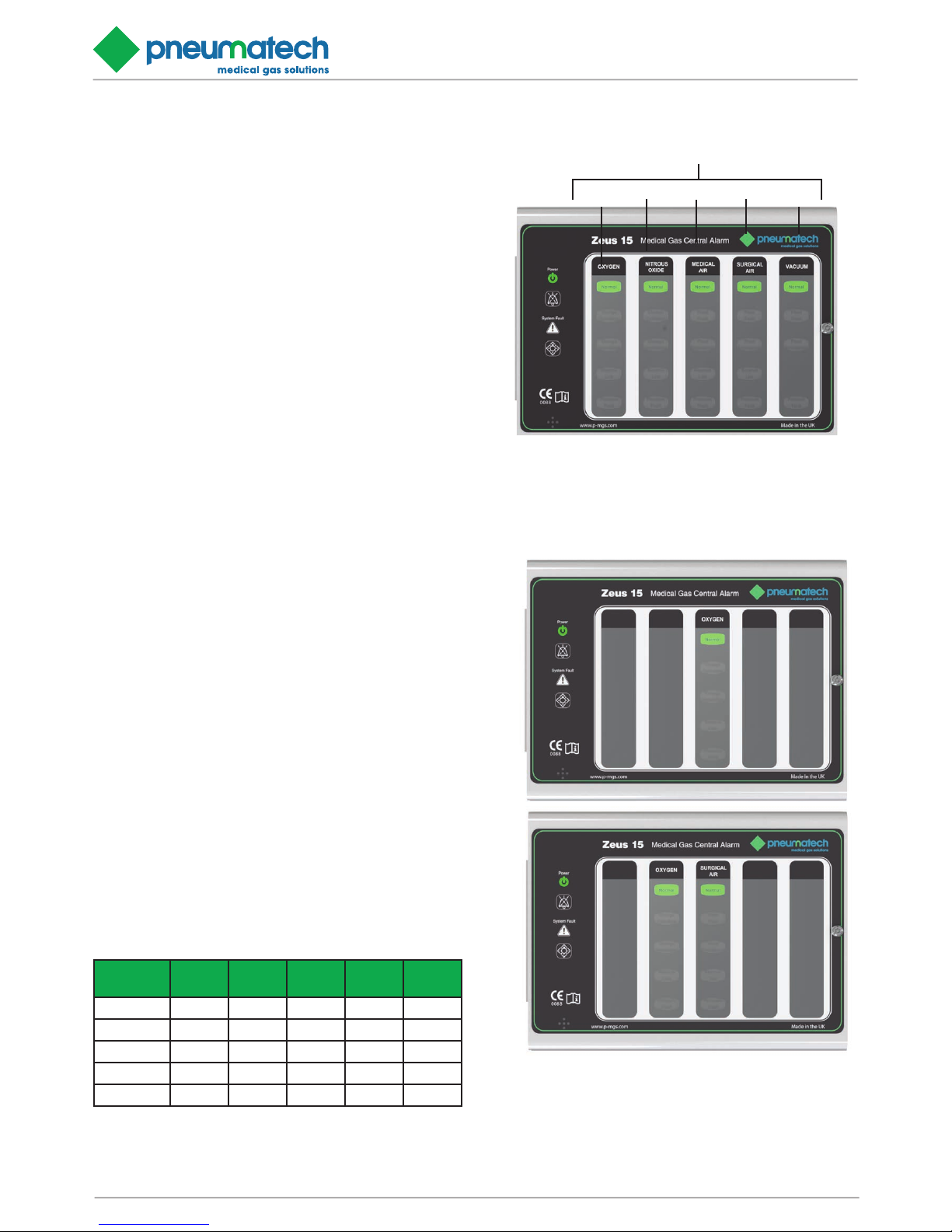
When an alarm panel is required to display less than its
maximum of 5 gas services, it is recommended that displays are positioned in accordance with the following (see
figure 2.4 & table 2.1):
TABLE 2.1: RECOMMENDED DISPLAY POSITIONS
Display
column
1 2 3 4 5
1 gas Gas 1
2 gas Gas 1 Gas 2
3 gas Gas 1 Gas 2 Gas 3
4 gas Gas 1 Gas 2 Gas 3 Gas 4
5 gas Gas 1 Gas 2 Gas 3 Gas 4 Gas 5
FIGURE 2.4 - EXAMPLES OF RECOMMENDED DISPLAY
POSITIONS
TYPICAL 1 GASTYPICAL 2 GAS
FIGURE 2.3- LEGEND INSTALLATION
Col. 5
Col. 4
Col. 3
Col. 2
Col. 1
GAS LEGEND INSTALLATION SLOTS
Page 16
Zeus Central 15 Alarm Page 16
Installation, Operation and Maintenance Manual
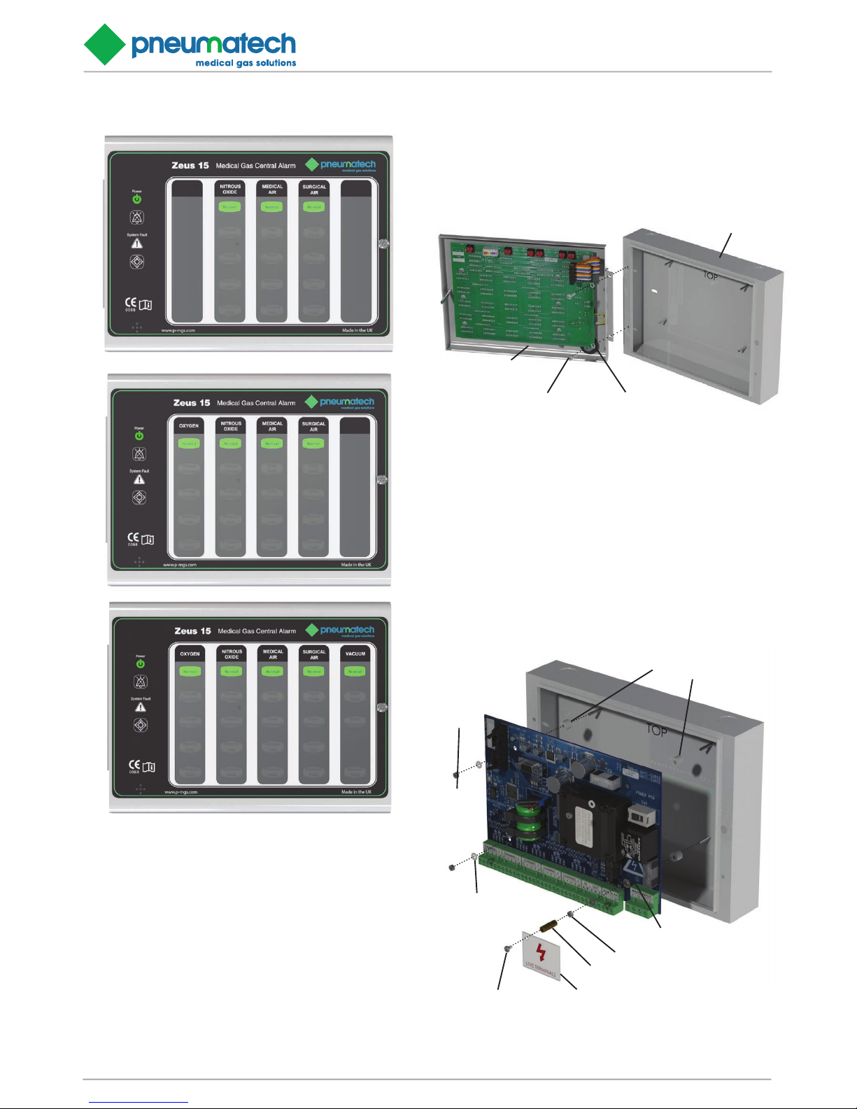
2.2.4 Power supply printed circuit board. Fit (see figure
2.6).
Fit a plastic spacer over each of the four retaining studs
in the backbox and locate the board on the studs. Fit the
washers and tighten nuts in place just enough to hold the
board and not crack it.
TYPICAL 4 GASTYPICAL 5 GAS TYPICAL 3 GAS
FIGURE 2.5 - DOOR INSTALLATION DETAIL.
M4 x 12 PAN HEAD x 2
DOOR ASSEMBLY
M4 x WASHER x 2
BACK BOX
2.2.3 Alarm panel front cover. Fit (SEE FIGURE 2.4).
Secure the front cover to backbox flange by securing
hinge to backbox with screws provided.
FIGURE 2.6 - POWER SUPPLY BOARD INSTALLATION DETAILS.
M3 NUT x 4
PLASTIC SPACERS x 4
9.5 OD x 8mm LONG
POWER SUPPLY BOARD
M3 STEEL WASHER x 1
M3 x 18 HEX SPACER
TERMINAL SHIELD
M3 x 5 PAN HEAD
M3 NYLON
WASHER x 3
Page 17
Installation, Operation and Maintenance Manual
Zeus Central 15 Alarm Page 17
CAUTION... Printed circuit boards are susceptible to damage by static electricity and must remain enclosed in their
anti-static packaging until immediately required for use.
Removed printed circuit boards must be placed in their
anti-static packaging immediately on removal. To prevent
damage to printed circuit boards, handle with care and do
not over torque retaining nuts.
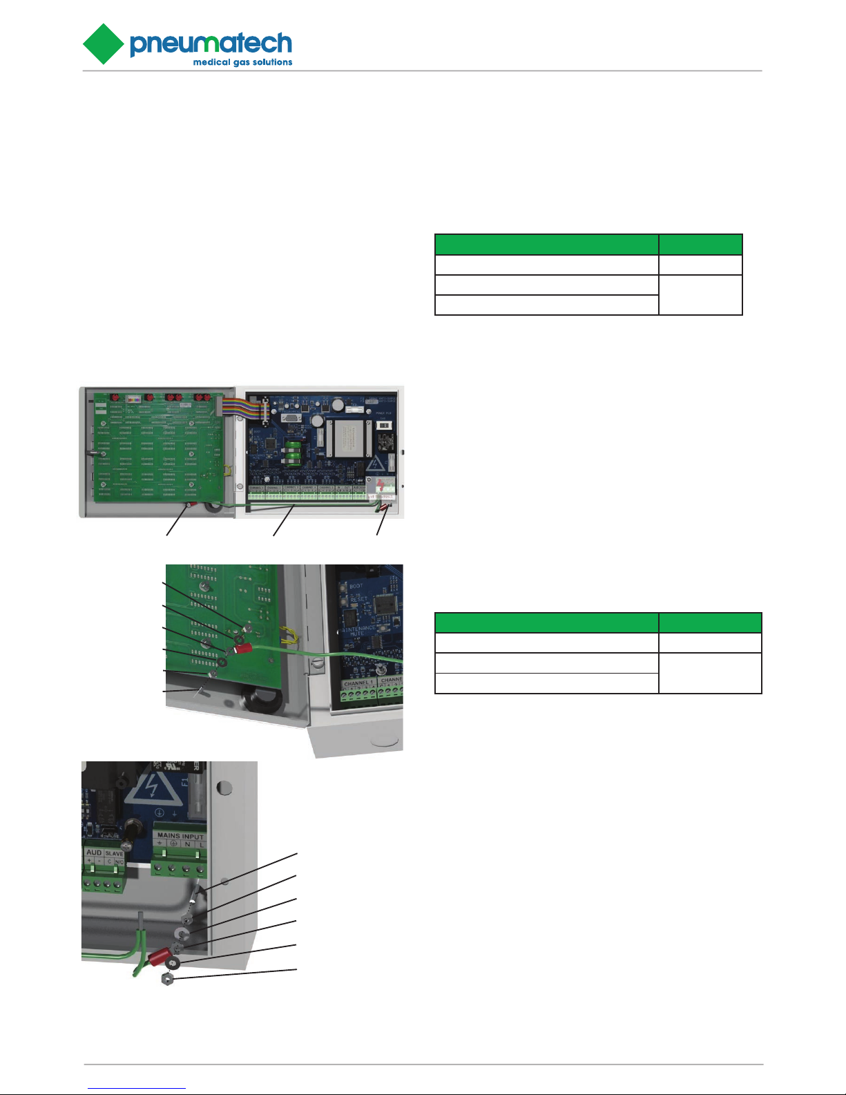
2.2.5 Electrical bonding lead. Fit (see figure 2.7).
Connect the flying earth lead from the power supply PCB
mains terminal ‘E’ to the earthing stud in the alarm panel
backbox and alarm panel front cover.
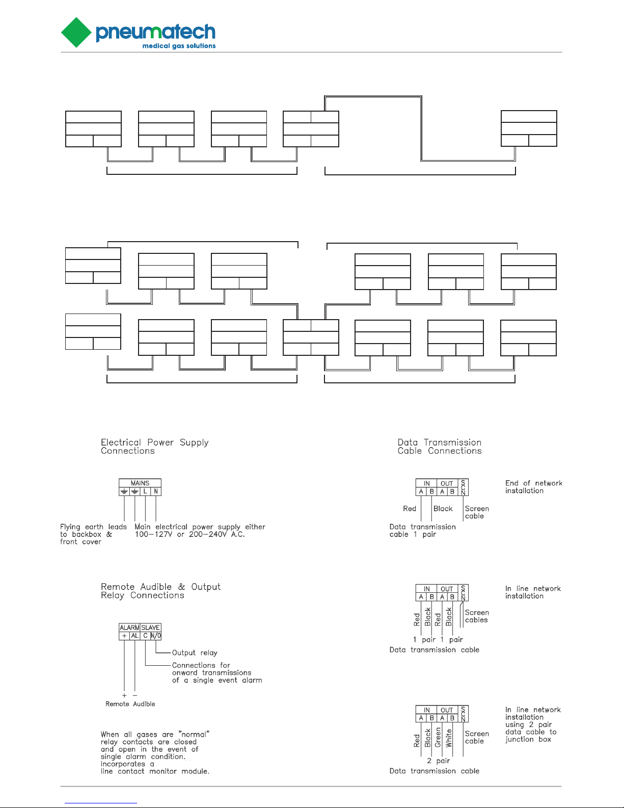
2.2.6 Cable Installation - Data Cable
Details for the cable connections can be seen on figure
2.8 typical wiring diagrams can be seen on figure 2.9.
The Zeus 15 uses the EIA/TIA-485 (RS-485) data communications specification. Cable used for the alarm data
must be suitable for these signals. Pneumatech MGS recommends the following cable types
Manufacturer / Reference Part Number
Belden 8132 (2 pr, Non-Plenum) 6000174
Belden 82842 (2 pr, Plenum)
Alphawire 6455 (2 pr, Non-Plenum)
If segment lengths longer than 1200 metres, or non-standard network topologies are required, a signal booster /
splitter is available. See figure 10 for examples. Pneumatech MGS recommend installation of 2 pair cable, such
that a spare pair is available, if needed.
2.2.7 Cable Installation - Input Cable
Details for the cable connections can be seen on figure 9,
typical wiring diagrams can be seen on figure 2.9.
The Zeus 15 uses Pneumatech MGS Line continuity
monitoring on all input signals. This type of connection is
relatively immune to interference. Shielded cable is not a
requirement, however, in extremely electrical noise shielding may be necessary. Pneumatech MGS recommends
the following cable types, and a maximum length of 100
metres.
Manufacturer / Reference Part Number
Alphawire 1175C (Unshielded) 6000174
Alphawire 1175L (Unshielded, LSZH)
Alphawire 1295C (Shielded)
FIGURE 2.7 - EARTH LEAD ASSEMBLY DETAILS.
EARTH STUD
EARTH LEAD
EARTH STUD
M3 NUT
M3 WASHER
EARTH LEAD
M3 WASHER
M3 NUT
M3 STUD
M3 NUT
M3 STUD
M3 WASHER
EARTH LEAD
M3 NUT
M3 WASHER
Page 18
Zeus Central 15 Alarm Page 18
Installation, Operation and Maintenance Manual
FIGURE 2.8 - Zeus 15 EXAMPLE MAXIMUM OF CABLE SEGMENTS
Zeus 15
DATA
IN OUT
Zeus 15
DATA
IN OUT
Zeus 15
DATA
IN OUT
IN OUT
BOOSTER
IN OUT
Zeus 15
DATA
IN OUT
LENGTH OF SEGMENT <1200 METRES LENGTH OF SEGMENT <1200 METRES
Zeus 15
DATA
IN OUT
Zeus 15
DATA
IN OUT
Zeus 15
DATA
IN OUT
IN OUT
BOOSTER
IN OUT
LENGTH OF SEGMENT <1200 METRES
Zeus 15
DATA
IN OUT
Zeus 15
DATA
IN OUT
Zeus 15
DATA
IN OUT
Zeus 15
DATA
IN OUT
Zeus 15
DATA
IN OUT
Zeus 15
DATA
IN OUT
Zeus 15
DATA
IN OUT
Zeus 15
DATA
IN OUT
Zeus 15
DATA
IN OUT
LENGTH OF SEGMENT <1200 METRES
LENGTH OF SEGMENT <1200 METRES
LENGTH OF SEGMENT <1200 METRES
2 segment network with a single, distant panel.
2 segment network arranged as a physical cross.
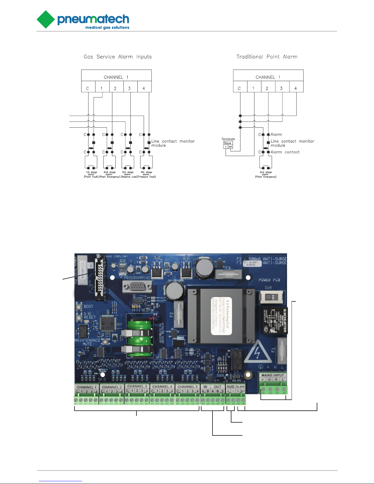
FIGURE 2.9 - Zeus 15 TYPICAL WIRING DIAGRAMS
Zeus 15 Alarm Terminals
Zeus 15 Alarm Terminals
Zeus 15 Alarm Terminals
Zeus 15 Alarm Terminals
Zeus 15 Alarm Terminals
PneumatechMGS
Page 19
Installation, Operation and Maintenance Manual
Zeus Central 15 Alarm Page 19
FIGURE 2.11 - Zeus 15 POWER SUPPLY BOARD CONNECTION LAYOUT
MULTI-WAY
DATA RIB-
BON FROM
LIGHT
BOARD
INPUTS FOR DISPLAY COLUMNS 1-5
[COMMON] [FAULT CONDITIONS 1-4]
NOTE - FAULT CONDITION 1 COINCIDES WITH THE TOP FAULT
CONDITION LED, WORKING DOWN IN ORDER
DATA TRANSMISSION CONNECTIONS
IN [A] [B], OUT [A] [B] AND [SCREEN]
REMOTE AUDIBLE CONNECTION [+] [-]
OUTPUT RELAY
FOR
TRANSMITTING
SINGLE
EVENT ALARM
[COMMON] [N/O]
MAIN POWER
CONNECTION
[BONDING EARTH]
[MAIN EARTH]
[NEUTRAL] [LIVE]
Zeus 2.10 Typical Input Connecon
Notes...
1. If connected to Pneumatech MGS plant, line connuity
monitors are integral to the plant.
2. Unused terminals must be linked out with linking resistors
provided.
Notes...
1. A maximum of four point alarms may be connected to any
channel.
2. Unused terminals must be linked out with linking resistors
provided.
Zeus 15 Alarm Terminals Zeus 15 Alarm Terminals
Zeus 6
Page 20

Zeus Central 15 Alarm Page 20
Installation, Operation and Maintenance Manual
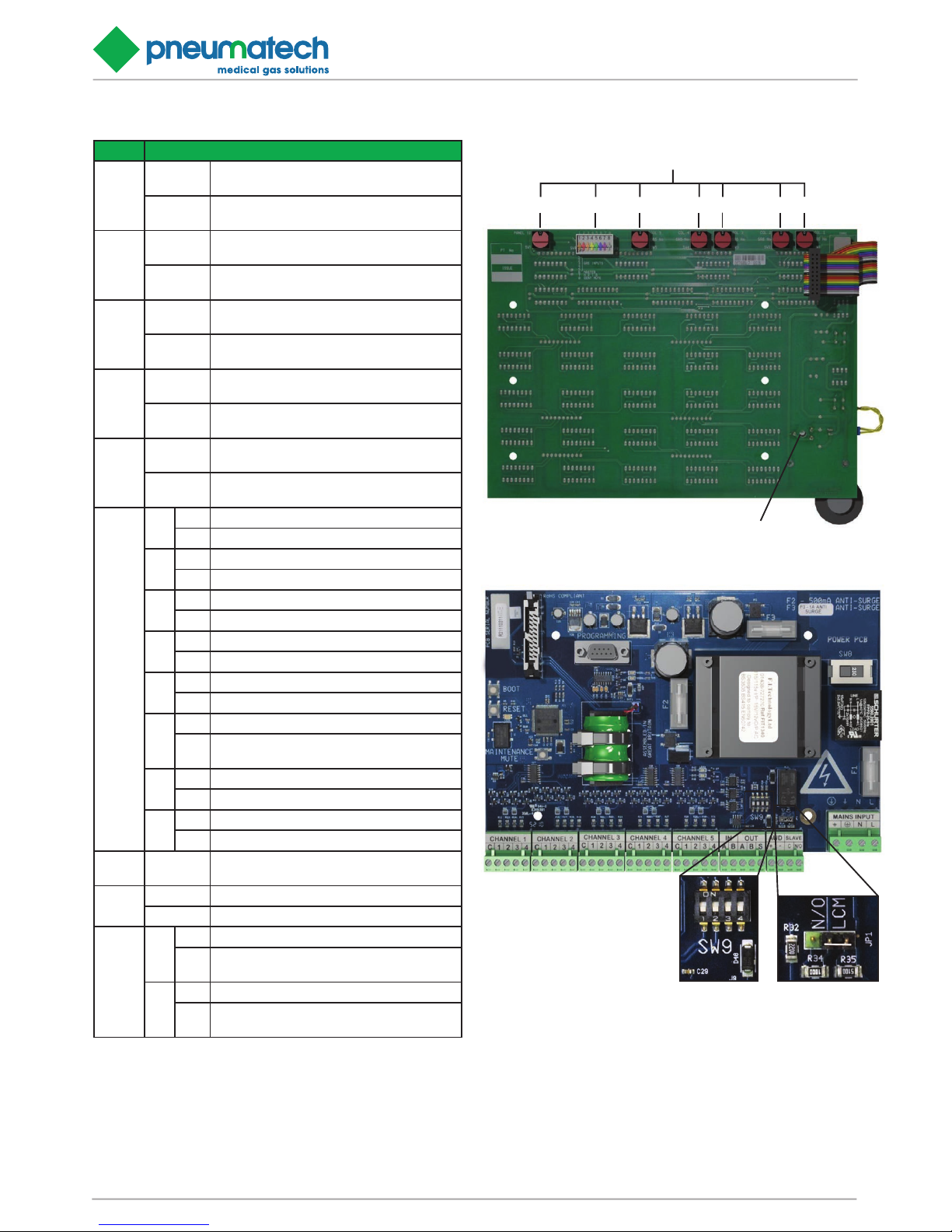
3.0 Programming of the alarm system
The Zeus 15 central alarm system panels are programmed
by setting a series of DIL and rotary switches on the rear
of the light display board (see figure 3.3), as detailed in
table 4. Rotary switches SW1 to SW5 assign the display
columns to a specified input, or OFF. 1 to F correspond to
‘normal’ medical gas alarms, i.e. Normal + 4 alarm conditions with an audible on all alarm conditions. 8-way DIL
switch SW6 sets details specific to each panel. Rotary
switch SW7 sets the panel ID. Similar switches are on the
rear of the relay board in a Zeus 15 relay interface panel.
The Zeus 15 central alarm system works by identifying
each individual gas channel or set of point alarm inputs
with a unique ID and by identifying each panel with a
unique ID. The rotary switches are hexadecimal i.e. A corresponds to 10, B corresponds to 11 etc. for purposes of
panel Ids. A channel must be set between 0 and F, 0 being
OFF.
SW7 in conjunction with SW6-7 give each individual panel
an ID between 0 and 31. The alarm panel with the highest
ID must be set as the MASTER panel (SW6-6 ON), all
other panels (including Zeus 15 Relay panels) must be
set as slave panels (SW6-6 OFF). Therefore one alarm
system may contain up to 32 panels the highest number
being set as the MASTER.
SW6-8 enables or disables the central acknowledge facility, ON enabled, OFF disabled. When the mute switch
is operated on a central acknowledge panel displaying a
fault condition, the flashing light on all panels showing the
same fault changes from flashing to steady, and the audible alarm is muted for that particular gas.
NB there may be more than one central acknowledge
panel on a system (i.e. two panels in the telephone exchange on a 10 gas system), but there must be only one
master panel on the system and it must have the highest
panel ID on the system.
SW6-1 to SW6-5 are used to identify where each channel is input onto the system. If these switches are set to
ON then this means that a particular gas or set of point
alarms is input to this panel. On a complete system there
should only be as many of these switches set to ON as
there are channels on the complete system. When set to
ON the alarm panel will look for a complete set of inputs,
i.e. four fault conditions. If less than four inputs are been
connected to a particular channel then the linking resistors provided must be used to “link out” the unused conditions. I.e. if a C11 vacuum plant is to be connected, then
the input alarm conditions would be connected between
Common, 1, 2 and 4. Therefore a linking resistor must be
connected between Common and 3.
An alarm system is set up by allocating a number (1 to 9)
or letter (A to F) to each set of plant inputs or point alarm
inputs. Typically on a 4 gas system with point alarms:-
1 – Oxygen Manifold Alarms
2 – Nitrous Oxide Manifold Alarms
3 – Air Plant Alarms
4 – Vacuum Plant Alarms
A – Ward 1 to 4 Point Alarms
B – Ward 5 to 8 Point Alarms
Therefore on every panel where Oxygen is to be displayed
the appropriate gas number switch (SW1 to SW5) is set
to 1. Where inputs are connected into the system the appropriate DIL switch (SW6-1 to SW6-5) must be set ON.
For example, if air and vacuum plant are both input into
channels 2 and 3 on a two gas panel in the plant room,
then SW2 must be set to 3 to display air plant, SW3 must
be set to 4 to display vacuum plant. SW1, SW4 and SW5
must be set to 0. Also SW6-2 and SW6-3 must be set to
ON to indicate that these alarms are input to this panel.
SW8 selects the voltage range of the power supply, either
230V±10% or 115V±10%.
SW9 selects the termination and fail safe biassing options
for the RS-485 port. A network is divided up into segments.
Each segment can be up to 1200 metres (see figure 3.1
for examples), subject to cable type and site conditions.
For the two panels at the endpoints of each cable segment
on a network, the termination resistor should be switched
on with SW9-1 and SW9-2. For all other panels, SW9-1
and SW9-2 should be switched off. If a signal booster is
the endpoint of a cable segment, the termination resistor of the booster should be enabled. See the instruction
manual enclosed with the signal booster for more details.
For each cable segment on a network the fail safe resistors should be enabled on a single panel, by switching on
SW9-3 and SW9-4. For all other panels, SW9-3 and SW94 should be switched off.
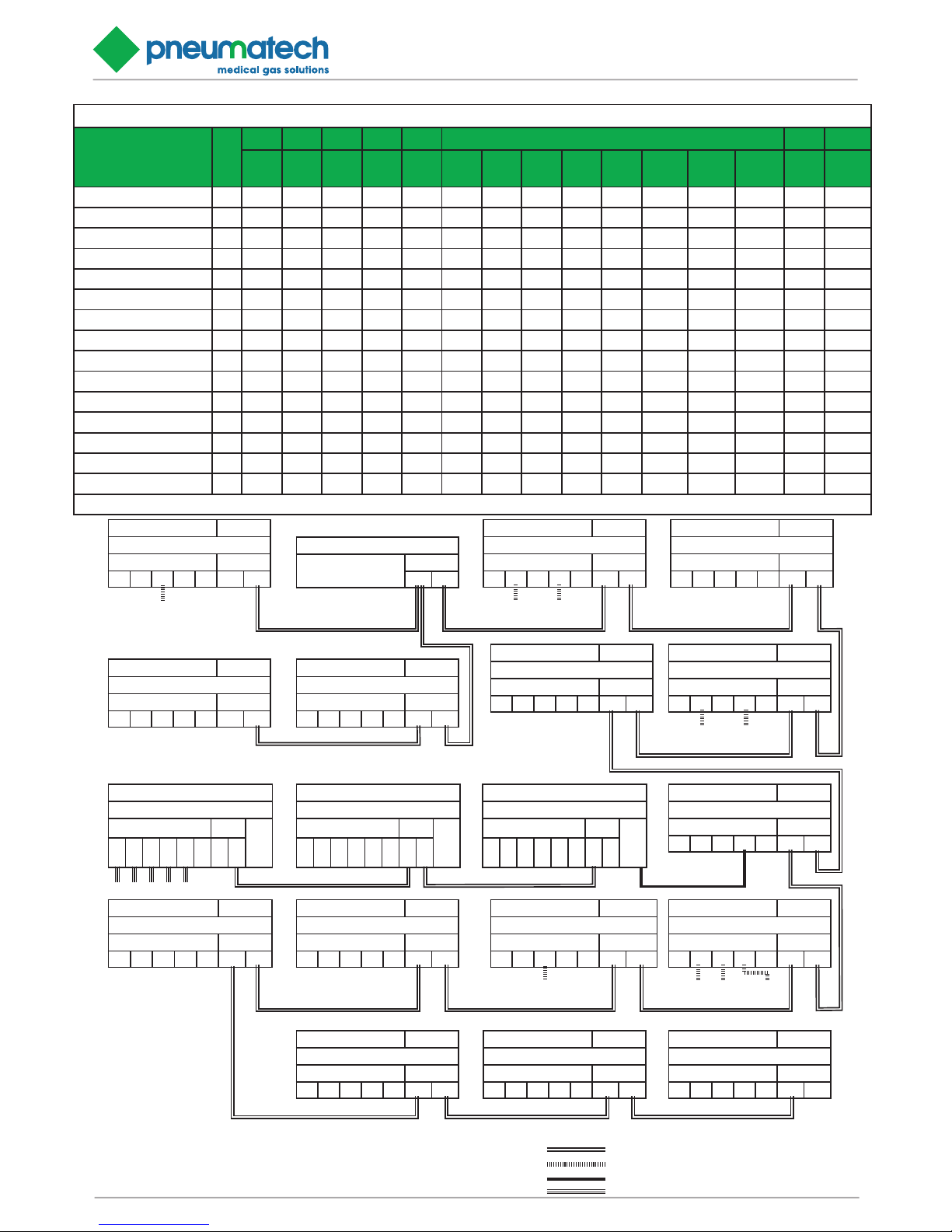
See figure 3.1 for example of programming settings for a
typical installation. Table 2 shows a summary of the programming switch functions
NOTE:
Whenever the programming switches on the light board
are changed, it is necessary to reset the alarm by pressing the reset button, or by cycling the power, to read in the
new configuration values. 1.12 Programming of the alarm
system
Page 21
Installation, Operation and Maintenance Manual
Zeus Central 15 Alarm Page 21
FIGURE 3.1 - EXAMPLE OF PROGRAMMING SWITCH SETTINGS FOR A TYPICAL INSTALLATION INCLUDING Zeus 15, Zeus 6
NOTES...
Columns marked * indicate that gas service is input at
that panel
Maximum length of data cable segments is 1200 metres
Maximum length of input cable segments is 100 metres
Maximum length of remote audible cables is 50 metres
Switch sengs for example installaon
Panel Locaon
TYPE
SW1 SW2 SW3 SW4 SW5 SW6 SW7 SW9
C1
Gas 1
C2
Gas 2C3Gas 3C4Gas 4C5Gas 5C1InputC2InputC3InputC4InputC5Input
Master
Panel
ID High
Master
Mute
PanelIDRS485
TERM
Vie I 0 0 1* 0 0 OFF OFF ON OFF OFF OFF OFF OFF 0 ON
Estates 1 R 1 2 3 4 5 OFF OFF OFF OFF OFF OFF OFF OFF 1 ON
Estates 2 R 6 7 8 9 A OFF OFF OFF OFF OFF OFF OFF OFF 2 OFF
South Plant Room I 0 5* 0 8* 0 OFF ON OFF ON OFF OFF OFF OFF 3 OFF
Day Surgery R 1 3 5 8 0 OFF OFF OFF OFF OFF OFF OFF OFF 4 OFF
Manifold Room 1 I 0 2* 0 3* 0 OFF ON OFF ON OFF OFF OFF OFF 5 OFF
Theatre Recepon 1 R 1 2 3 6 7 OFF OFF OFF OFF OFF OFF OFF OFF 6 OFF
Theatre Recepon 2 RI 0 9 0 A* 0 OFF OFF OFF ON OFF OFF OFF OFF 7 OFF
North Plant Room I 0 6* 7* 9* 0 OFF ON ON ON OFF OFF OFF OFF 8 OFF
Maternity Manifold Room I 0 0 4* 0 0 OFF OFF ON OFF OFF OFF OFF OFF 9 OFF
Maternity R 1 4 6 9 0 OFF OFF OFF OFF OFF OFF OFF OFF A OFF
Relay Interface 1 RL 1 2 3 4 5 OFF OFF OFF OFF OFF OFF OFF OFF B ON
Relay Interface 2 RL 6 7 8 9 A OFF OFF OFF OFF OFF OFF OFF OFF C OFF
Telephone Exchange 1 R 1 2 3 4 5 OFF OFF OFF OFF OFF OFF OFF OFF D OFF
Telephone Exchange 2 R 6 7 8 9 A OFF OFF OFF OFF OFF ON OFF OFF E OFF
* marks the channel as an input, Type ‘I’ - Input panel, Type ‘R’ - repeater panel, Type ‘RI’ - repeater/input panel, Type ‘R’ - relay interface panel
Zeus 15 ID: 0
LOCATION: VIE
COLUMN INPUTS D ATA
0 0 1* 0 0 IN OUT
OXYGEN
SUPPLY
Zeus SIGNAL BOOSTER/SPLITTER
LOCATION:
SOUTH PLANT ROOM
DATA
A B
Zeus 15 ID: 3
LOCATION: SOUTH PLANT ROOM
COLUMN INPUTS D ATA
0 5* 0 8* 0 IN OUT
MEDICAL AIR VACUUM
SOUTH SOUTH
Zeus 15 ID: 4
LOCATION: DAY SURGERY
COLUMN INPUTS D ATA
1 3 5 8 0 IN OUT
Zeus 15 ID: 2
LOCATION: ESTATES 2
COLUMN INPUTS D ATA
6 7 8 9 A IN OUT
Zeus 15 ID: 1
LOCATION: ESTATES 1
COLUMN INPUTS D ATA
1 2 3 4 5 IN OUT
Zeus 15 ID: 6
LOCATION: THEATRE 1
COLUMN INPUTS D ATA
1 2 3 6 7 IN OUT
Zeus 15 ID: 5
LOCATION: MANIFOLD ROOM
COLUMN INPUTS D ATA
0 2* 0 3* 0 IN OUT
OXYGEN NITROUS
MANIFOLD OXIDE
Zeus 15 ID: 7
LOCATION: MANIFOLD ROOM
COLUMN INPUTS D ATA
0 9 0 A* 0 IN OUT
Zeus 6
LOCATION: THEATRE RECEPTION
COLUMN INPUTS DATA
RELAY
[C] [N/O]
O2
N2O
MA 4
MA 7
VAC
0
IN
OUT
Zeus 6
LOCATION: THEATRE 1
COLUMN INPUTS DATA
RELAY
[C] [N/O]
O2
N2O
MA 4
MA 7
VAC
0
IN
OUT
Zeus 6
LOCATION: THEATRE AVSUs
COLUMN INPUTS DATA
RELAY
[C] [N/O]
O2
N2O
MA 4
MA 7
VAC
0
IN
OUT
PRESSURE SWITCH INPUTS
Zeus 15 ID: 8
LOCATION: NORTH PLANT ROOM
COLUMN INPUTS D ATA
0 6* 7* 9* 0 IN OUT
MEDICAL SURGICAL VACUUM
AIR NORTH AIR NORTH
Zeus 15 ID: 9
LOCATION: MATERNITY MANIFOLD ROOM
COLUMN INPUTS DATA
0 0 4* 0 0 IN OUT
ENTONOX
Zeus 15 ID: A
LOCATION: MATERNITY UNIT
COLUMN INPUTS D ATA
1 4 6 9 0 IN OUT
Zeus 15 (MASTER) ID: E
LOCATION: TELEPHONE EXCHANGE 2
COLUMN INPUTS DATA
6 7 8 9 A IN OUT
Zeus 15 ID: D
LOCATION: TELEPHONE EXCHANGE 1
COLUMN INPUTS D ATA
1 2 3 4 5 IN OUT
Zeus 15 RELAY INTERFACE ID: C
LOCATION: TELEPHONE EXCHANGE R2
COLUMN INPUTS D ATA
6 7 8 9 A IN OUT
Zeus 15 RELAY INTERFACE ID: B
LOCATION: TELEPHONE EXCHANGE R1
COLUMN INPUTS D ATA
1 2 3 4 5 IN OUT
CABLE TYPES
Belden 8729 2 pair RS485
Alphawire 117C 5 core
Alphawire B964011 1 pair
Alphawire 1173C 3 core
NOTES...
Columns marked * indicate that gas service is input at that panel
Maximum length of data cable segments is 1200 metres
Maximum length of input cable segments is 100 metres
Maximum length of remote audible cables is 50 metres
Page 22
Zeus Central 15 Alarm Page 22
Installation, Operation and Maintenance Manual
TABLE 3.2 Zeus 15 PROGRAMMING
Switch
Setting/description
SW1
0
Display channel 1 O, gas display
channel not used
1-F
Display channel 1 Normal gas
display HTM02-01
SW2
0
Display channel 2 O, gas display
channel not used
1-F
Display channel 2 Normal gas
display HTM02-01
SW3
0
Display channel 3 O, gas display
channel not used
1-F
Display channel 3 Normal gas
display HTM02-01
SW4
0
Display channel 4 O, gas display
channel not used
1-F
Display channel 4 Normal gas
display HTM02-01
SW5
0
Display channel 5 O, gas display
channel not used
1-F
Display channel 5 Normal gas
display HTM02-01
SW6
1
OFF Channel 1 display not input at this panel
ON Channel 1 display input to this panel
2
OFF Channel 2 display not input at this panel
ON Channel 2 display input to this panel
3
OFF Channel 3 display not input at this panel
ON Channel 3 display input to this panel
4
OFF Channel 4 display not input at this panel
ON Channel 4 display input to this panel
5
OFF Channel 5 display not input at this panel
ON Channel 5 display input to this panel
6
OFF to designate panel as slave
ON
to designate panel as master
(must be highest ID on system)
7
OFF for panel ID 0 to 15
ON or panel ID 16-31
8
OFF to disable central acknowledge facility
ON to enable central acknowledge facility
SW7 0-F
Sets panel ID 0 to 15 or 16 to 31 in
conjunction with SW6-7
SW8
115 Set voltage to 115V±10%
230 Set voltage to 230V±10%
SW9
1-2
OFF to disable RS485 termination
ON
to enable RS485 termination
(on cable segment endpoints only)
3-4
OFF to disable RS485 fail safe biassing
ON
to enable RS485 fail safe biassing
(on one panel per cable segment only)
NOTE:
Switches SW8 and SW9 are on the power PCB (see figure 3.3). All other switches are on the light PCB
CONFIGURABLE DIP
SWITCHES FOR DATA
TRANSMISSION
JUMPER JP1
(SEE NOTE)
FIGURE 3.3 - Zeus 15 PROGRAMMING SWITCHES
PROGRAMMING SWITCHES (SEE SECTION 1.12)
AUDIBLE WARNING VOLUME CONTROL
SW1SW2SW3SW4SW5SW6SW7
Page 23

Installation, Operation and Maintenance Manual
Zeus Central 15 Alarm Page 23
4.5 Check the audible warning
Whilst carrying out paragraph 2.4, ensure that audible
warning sounds for the appropriate alarm conditions. Ensure the operation of the MUTE switch cancels the audible
and that the audible comes on again after approximately
15 minutes.
4.6 Check the Remote Audible
Check that all remote audibles operate whenever there is
an alarm condition on its parent panel. Check that the remote audible is silenced by operation of the MUTE switch
on parent panel.
4.7 Checking the Relay Interface panel
If a relay interface panel is used with the alarm system,
its operation must be checked whilst checking each gas
service status applicable to the panel. With a gas service
operating ‘normally’ the appropriate relay should be energised and it’s contacts should be closed (see document
number 2005202 for more details).
4.8 Checking the SYSTEM ALARM indication
The procedure for checking that the SYSTEM ALARM circuits are operating correctly is as follows, and should be
carried out on all alarm panels:-
Electrical power supply. Switch OFF
Indications. Check.
Check that POWER ON LED is extinguished and SYSTEM ALARM LED is illuminated (flashing), accompanied
by an audible warning (see table 3) after 30 seconds. If
the panel receives an input, ensure that the gas display
on all panels displaying that particular gas service have
illuminated (flashing) LED’s for all input alarm stages and
the SYSTEM ALARM LED illuminates with an audible
warning.
Electrical power supply. Switch ON.
Ensure that all indications return to NORMAL (see table
3), including displays on repeater panels.
Alarm panel front cover. Open.
Line continuity monitoring. Check open circuit.
Disconnect input plug from gas service channel on power
supply PCB (see figure 1.5). Check that the respective
gas service channel indicates NORMAL and that all ‘alarm
conditions’ are steady illuminations. Check that SYSTEM
ALARM LED illuminates (flashing) accompanied by an
audible warning. Press the TEST switch (see figure 1.1)
and ensure that all alarm LED’s flash at a slower rate than
other displays (see table 1.2). Check that all repeater pan-
4. COMMISSIONING
4.1 Introduction
Commissioning of the Zeus 15 medical gas central alarm
installation is carried out in full after initial installation and
the appropriate sections must be carried out after a major component change. The object of commissioning is to
ensure that all components are serviceable and correctly
programmed.
The commissioning procedure also ensures that anticonfusion checks are carried out and that the correct gas
service is displayed in the designated column. Personnel
carrying out the following commissioning procedure must
be qualified and fully conversant with the information contained in this manual.
WARNING:
Before commencing the commissioning procedure, ensure that all installation procedures are complete and that
all wiring is correctly connected. Before switching on the
mains electrical supple, ensure the supply is correctly
fused.
4.2 Functional testing
When all alarm panels have been installed and connected, the following must be carried out on every alarm panel
in the systems. Commence the procedure at alarm panels
which receive an input and progress until all ‘input’ panels are proven. Carry out the procedure on the ‘central’
panel(s). Repeat the procedure on all ‘repeater’ panels
including those previously checked as input panels, Ensure that all gas service displays and all alarm panels are
proven.
4.3 Basic Checks
Check the multi-way ribbon cable is correctly connected
(see figures 2.7 & 2.11). Switch ON electrical power supply to alarm panel. Check that the POWER ON LED illuminates. Press the TEST switch and check that all the alarm
panels LED’s illuminate (flashing) and the audible warning
sounds (see figure 1.1 and table 1.2).
4.4 Check alarm conditions
Taking each gas service in turn, ensure that the NORMAL indication is illuminated in the correct display column
on all panels displaying that gas service, when the gas
service is set to work normally. Set the gas service to introduce the 1st, 2nd, 3rd and 4th alarm conditions and ensure that the correct alarm light illuminates in each case.
Throughout the procedure, ensure that the LED’s are the
correct colour and gas service legends are correct and in
accordance with the correct specification. This check must
be carried out on all panels displaying that particular gas
service.
Page 24

Zeus Central 15 Alarm Page 24
Installation, Operation and Maintenance Manual
els which display that input indicate all ‘alarm conditions’
and SYSTEM ALARM in a flashing mode.
Input. Reconnect.
Reconnect the input plug to gas channel ensure that all
indications are NORMAL. Repeat with all other inputs.
Line continuity monitoring. Check short circuit.
Using a small piece of wire as a shorting link, short out
input terminals (C and either terminal 1, 2, 3 or 4 as applicable, see figure 1.5). Check that the respective gas service display indicates NORMAL and that the respective
‘alarm condition’ illuminates (steady), see table 2). Check
that the SYSTEM ALARM LED illuminates (flashing) accompanied by an audible warning. Press the TEST switch
(see figure 1.1) and ensure that the respective ‘alarm condition’ flashes at a faster rate than other displays.
Shorting link. Remove.
Remove shorting link and repeat above step with all other inputs. On completion, ensure that all indications are
NORMAL.
Alarm panel front cover. Close and secure.
4.9 Check Central Acknowledge function
With an alarm condition illuminated in flashing mode,
operate MUTE switch (see figure 1.1) on a designated
central acknowledge panel. Check all repeater and input
panels displaying that alarm condition revert to a steady
alarm indication.
4.10 Setting the alarm system
Ensure that all alarm panels are closed and secured. Ensure that each gas service installation is operating normally and only NORMAL indications are displayed.
5. OPERATING INSTRUCTIONS
WARNING:
Any alarm condition must be investigated and the gas service returned to normal as soon as possible.
CAUTION:
The TEST and MUTE switches must only be operated by
gentle finger pressure. Operation by use of instruments,
tools or other implements will cause damage to the switch.
5.1 General operation
During normal conditions the green (normal) LED’s are
illuminated. Should a service failure sensor operate, the
green (normal) LED is extinguished and the appropriate
alarm mode LED (yellow or red) is illuminated and the
audible warning sounds, if required (see table 3). The audible warning will continue until either the MUTE switch
is pressed or the gas service is returned to normal. If the
mute facility is operated, the audible warning will re-sound
after 15 mins, until either the MUTE switch is re-selected
or the gas service is returned to normal. Should a further alarm condition occur after the panel has indicated
an alarm and has been muted, the audible warning is reactivated.
5.2 System Alarm light
Should the SYSTEM ALARM light illuminate, a fault within
the alarm system has occurred. The fault must be investigated and rectified immediately.
5.3 Test switch operation
Pressing the TEST switch illuminates (flashing) all LED’s
within a panel and sounds the audible warning (see figure
1.1 & table 1.2).
5.4 Mute switch operation
Operation of the MUTE switch (see figure 1.1) following
an alarm condition will switch off the audible warning. The
audible warning will resound after 15 mins until either the
MUTE switch is re-selected or the gas service returns to
NORMAL.
6. MAINTENANCE
6.1 Introduction
Zeus 15 gas central alarm systems are designed to operate with the minimum of maintenance, however regular minor maintenance operations are recommended to
prove the system integrity. Maintenance operations are
carried out in accordance with the planned preventative
maintenance contract purchased by the customer. Maintenance engineers must fully understand the alarm system
and must be conversant with the information contained in
this manual.
WARNING:
Obtain a work permit before commencing any work on a
medical alarm system.
6.2 Tools and equipment
Except for the special key provided, no special tools are
required, however common hand tools are required and
they must be clean and serviceable. All necessary spare
parts must be obtained before commencing work.
6.3 Customer recommended maintenance
The following routine operations are the recommended
minimum:-
Page 25
Installation, Operation and Maintenance Manual
Zeus Central 15 Alarm Page 25
LIGHT BOARD
(P/N 6000169)
MULTI-WAY RIBBON CON-
NECTOR
LIGHT BOARD FASTENER
M3 NUTS (5.5 A/F)
& M3 NYLON WASHERS
POWER BOARD FASTENER
M3 NUTS (5.5 A/F)
& M3 WASHERS
M3 NYLON WASHERS
M3 STEEL WASHERS
M3 PILLAR (5.5 A/F)
M3 PAN HEAD MACHINE SET SCREW
GAS SUPPLY LEGEND
SLOTS
POWER SUPPLY BOARD
(P/N 6000168)
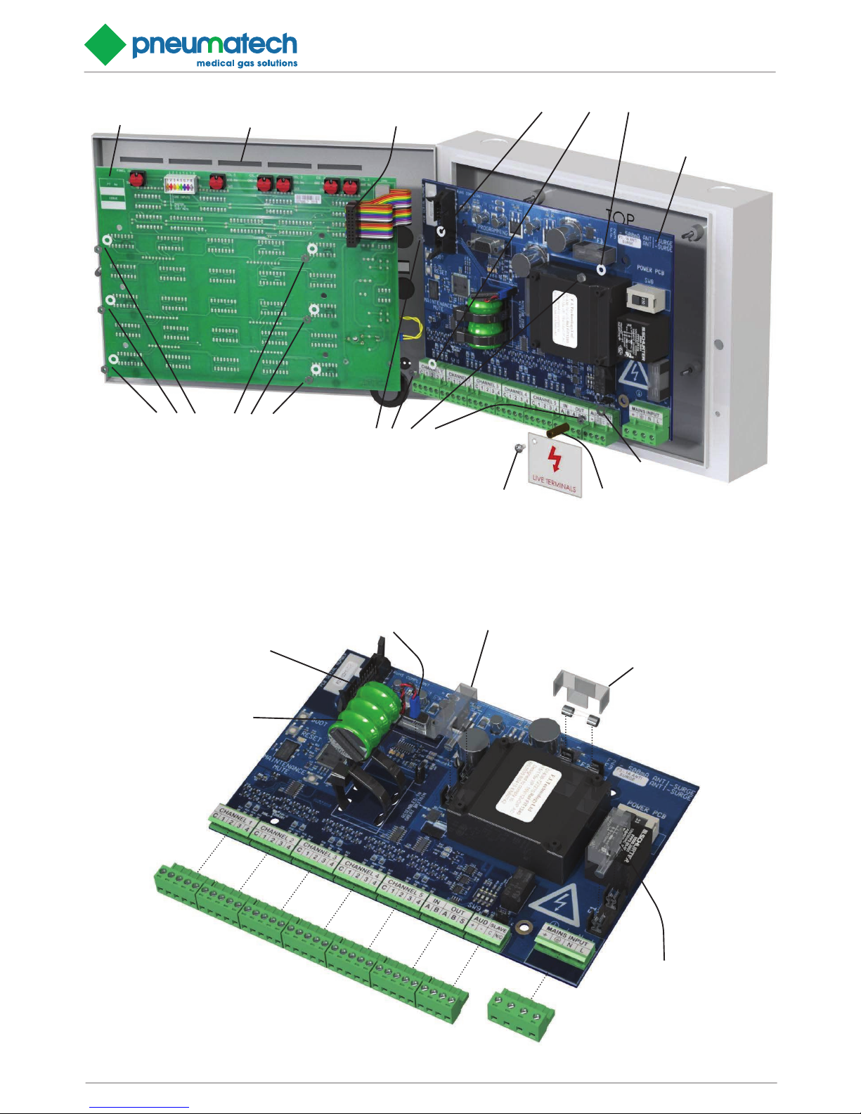
FIGURE 5.1 - POWER SUPPLY BOARD COMPONENT REPLACEMENT
BACKUP BATTERY
(P/N 1828825)
BACKUP BATTERY
CONNECTOR
F2 CLIP ON COVER
1A FUSE (P/N 1825372)
ELV 500mA FUSE [F3]
F3 CLIP ON COVER
500mA FUSE (P/N 1826675)
F3 CLIP ON COVER
500mA FUSE - 230V (P/N 1826675)
1A FUSE - 115V (P/N 1825372)
MULTI-WAY RIBBON CON-
NECTOR
NOTE....Make note of the respective positions of all the input
connectors prior to disconnection in preparation for reconnection
Page 26
Zeus Central 15 Alarm Page 26
Installation, Operation and Maintenance Manual
FIGURE 5.3- BOARD FUNCTION DIAGNOSTIC LED’S
LED 5LED 4
LED 1
LED 3
LED 2
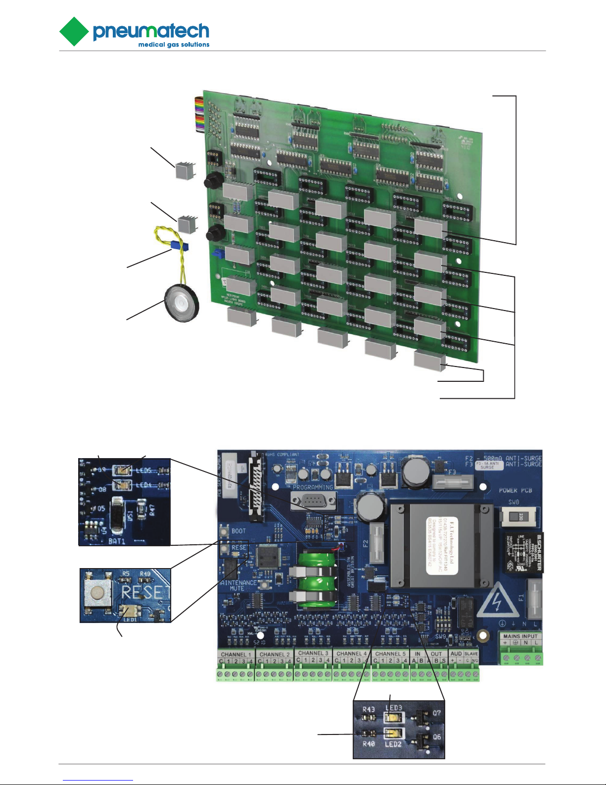
FIGURE 5.2 - LIGHT BOARD COMPONENT REPLACEMENT
ROW OF GREEN
LED’S (P/N 6000152)
ROW OF YELLOW LED’S (P/N 6000154)
ROW OF RED LED’S (P/N 6000153)
GREEN POWER ON
LED (P/N 6000155)
RED SYSTEM ALARM
LED (P/N 6000156)
SPEAKER
SPEAKER
CONNECTOR
Page 27
Installation, Operation and Maintenance Manual
Zeus Central 15 Alarm Page 27
6.4 Weekly inspection
Press the TEST button on each alarm panel and ensure
that all LED displays illuminate (flashing) and the audible
warning sounds. If the remote audible is connected to the
alarm panel, ensure that it operates simultaneously with
the panel.
6.5 Annual Inspection
The annual inspection proves the integrity of the interconnecting wiring between each gas service sensor and input
alarm panel, the line continuity monitoring circuits and the
integrity of the internal alarm panel circuits and interconnecting data transmission cable. The annual inspection
must be carried out on all alarm panels and consists of
the operations in paragraphs 2.3 to 2.10 inclusive.
6.6 Alarm Component Replacement
Figures 5.1, 5.2 & 5.3 gives details for replacing alarm
components
Figure 5.1 shows details for accessing the alarm panel
and disconnection the power supply and light board (see
section 1.7.1 figures 1.5, 1.6 and table 1.2 for setting up
a power board).
Figure 5.1 shows details for replacing the fuses, backup
battery and disconnecting the electrical and data sockets.
NOTE...
The replacement battery may take up to 72 hours to fully
recharge.
Figure 5.2 shows details for replacing LED’s and speaker.
WARNING:
ENSURE THAT THE MAINS ELECTRICAL SUPPLY IS
OFF AND REMAINS ISOLATED DURING WORK ON
THE INTERNALS OF THE ALARM PANEL.
CAUTION:
Printed circuit boards are susceptible to damage by static
electricity and must remain enclosed in their anti-static
packaging until immediately required for use. Removed
printed circuit boards must be placed in their anti-static
packaging immediately on removal. To prevent damage to
printed circuit boards, handle with care and do not over
torque retaining nuts.
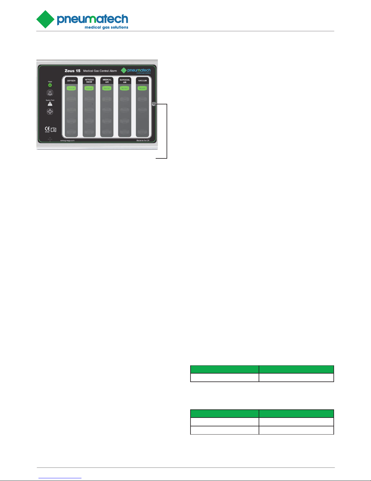
FIGURE 5.4 - POWER SUPPLY AND LIGHT DISPLAY PCB REPLACEMENT
SECURITY FASTENER
(Requires key, supplied with alarm panel
NOTE...
To access the LED’s the light board will need to be removed from the alarm panel (see figure 1.5)
Alarm panel test.
After performing any work on the alarm Ensure that POWER ON LED is illuminated and SYSTEM ALARM LED is
extinguished. Press TEST switch and ensure all LED’s
illuminate (flashing) and audible warning operates (see
Line continuity FAULT, TEST SWITCH on Figure1.1 and
table 1.2).
7. FAULT DIAGNOSIS
7.1 Introduction
The following tables detail possible defects/symptoms
which may occur with the Zeus 15 medical gas central
alarm system, with the necessary rectification action.
TABLE 7.1: TEST OR MUTE SWITCH FAILS TO OPERAT E
Possible cause Remarks/rectification action
1. Faulty switches Replace the light display PCB .
TABLE 7.2: SINGLE LED INDICATOR FAILS TO ILLUMINATE
Possible cause Remarks/rectification action
1. Faulty LED indicator Replace LED.
2. Faulty light display PCB. Replace light display PCB.
Page 28
Zeus Central 15 Alarm Page 28
Installation, Operation and Maintenance Manual
TABLE 7.3: ALARM PANEL LOSES ALL DISPLAYS EXCEPT SYSTEM ALARM
Possible cause
Remarks/rectification action
1. Mains electrical
power supply failure
Check mains electrical power supply into
the panel
2. Power supply fuses
blown
Check condion of fuses on power
supply PCB. Replace as necessary
3. Main ribbon
connector faulty
Check main ribbon connector on power
supply PCB. Replace power supply PCB
as necessary.
4. Main ribbon
damaged
Check main ribbon cable. If damaged
replace light display PCB.
5. Power supply PCB
faulty
Replace power supply PCB.
6. Light display PCB
faulty
If all other checks have failed to recfy
the fault, replace the light display PCB.
TABLE 7.4: SYSTEM ALARM/FAULT INDICATION WITH
A SERVICEABLE GAS
Possible cause
Remarks/rectification action
1. Electrical power
failure
Check POWER ON indicaon is
illuminated and other indicaons are
normal.
2. Gas service pressure
incorrect
Independently check gas service pressure
in area being monitored
3. Pressure switch
stuck in fail
Check resistance of interconnecng
wiring, line monitor module and
posion pressure switch.
(180Ω ± 5% with contacts closed), (690Ω
± 5% with contacts open). If value is
incorrect check connuity exists through
plant alarm relays/pressure switch. Check
pressure switch adjustment and replace
switch as necessary, complete with line
connuity module
4. Wiring defect
between panel and
pressure switch / plant
With a serviceable pressure switch ed,
check resistance of interconnecng
wiring and line monitor module (<10
ohms indicates a short circuit or >5K
ohms indicates an open circuit). Locate
wiring defect, repair as necessary or
replace line monitor module.
5. Main ribbon
connector faulty
Check main ribbon connector on power
supply PCB. Replace power supply PCB as
necessary.
6. Main ribbon
damaged
Check main ribbon cable. If damaged
replace light display PCB.
7. Power supply PCB
faulty
Replace power supply PCB.
8. Light display PCB
faulty
If all other checks have failed to recfy
the fault, replace the light display PCB.
TABLE 7.5: REMOTE ALARM/RECORDING SYSTEM
NOT OPERATING CORRECTLY
Possible cause
Remarks/rectification action
1. JP1 set
incorrectly
Check that the jumper on JP1 is set to
the correct posion.
2. Faulty interface relay With all gas services indicang
NORMAL, check that connuity exists
between both relay terminals (N/O
and C) on power supply PCB. With a
gas service failure indicaon, check
that relay contacts open and break the
circuit between the relay terminals.
Replace power supply PCB if relay
proves to be faulty.
3. Interconnecng
wiring faulty
With a serviceable relay ed and the
fault sll evident, the interconnecng
wiring to the remote system may be
faulty. Carry out connuity checks,
locate and recfy the defecve wiring
or replace.
4. Remote alarm system
faulty
Invesgate fault, repair or replace re-
mote system as necessary
TABLE 7.6: GAS SERVICE INDICATES NORMAL WITH
A GAS SERVICE FAILURE CONDITION
Possible cause Remarks/rectification action
1. Gas service
failure set incorrectly
Check that the gas service sensor is
operang at the correct pressure
2. Faulty wiring Carry out resistance checks between
input and alarm panel (Table 9). Repair/
replace defecve wiring as necessary
3. Power supply PCB
faulty
Replace power supply PCB
4. Light display PCB
faulty
If all other checks have failed to recfy
the fault, replace the light display PCB
TABLE 7.7: SYSTEM ALARM AND AUDIBLE FAIL TO
OPERATE ON POWER FAILURE
Possible cause
Remarks/rectification action
1. Back up baery
faulty
Replace back up baery.
2. Main ribbon
connector faulty
Check main ribbon connector on power
supply PCB. Replace power supply PCB
as necessary.
3. Main ribbon
damaged
Check main ribbon cable. If
damaged replace light display PCB.
4. Power supply PCB
faulty
Replace power supply PCB.
5. Light display PCB
faulty
If all other checks have failed to recfy
the fault, replace the light display PCB.
TABLE 7.8: A GAS SERVICE DISPLAY FLASHING (INCLUDING NORMAL) WITH SYSTEM ALARM
Notes…
Page 29
Installation, Operation and Maintenance Manual
Zeus Central 15 Alarm Page 29
1. Check status of other panels which display that particular gas service. If gas service display is flashing carry out
steps 1-5 inclusive.
2. If the gas display on other alarm panel is illuminated
carry out steps 4 and 5.
Possible cause
Remarks/rectification action
1. Power supply failure
to alarm panel which
receives input.
Check power supply to alarm panel
which receives gas service input
2. Faulty input/wiring Carry out resistance checks
between gas service sensor and input
alarm panel
3. Input power
supply
Replace power supply PCB
4. Transmission
between input
Check for connuity of data and
other panels faulty transmission cables
between panels. Repair/replace as
necessary
5. Light display faulty Either input or repeater panel may be
faulty. Replace light display PCB on input
panel. Replace light display PCB on
repeater panel.
TABLE 7.9: BOARD FUNCTION DIAGNOSTIC LED’S
LED No. Function Colour Status
LED 1 Heartbeat
Green - ashing OK
Yellow - ashing Fault
Red
Incorrect soware
for PCB
O Mains power o
LED 2
RS-485
Transmit
Acvity
Green - Blinking RS-485 transming
Solid or o No acvity
LED 3
RS-485
Receiver
Acvity
Red - Blinking RS-485 receiving
Solid or o No acvity
LED 4
RS-232
Transmit
Acvity
Green - Blinking RS-232 transming
Solid or o No acvity
LED 5
RS-232
Receiver
Acvity
Red - Blinking RS-232 receiving
Solid or o No acvity
For LED location on the power supply board see figure 12.
8. RECOMMENDED SPARES
TABLE 8.1 : LIST OF RECOMMENDED SPARES
Description Part Number
Power supply PCB (dual voltage) 6000168
Light display PCB 6000169
Back up baery assembly 6000157
Green LED array 6000152
Yellow LED array 6000154
Red LED array 6000153
Power on LED array 6000155
System alarm LED array 6000156
Fuse 500mA 6000159
Fuse 1A 6000160
Line connuity monitor (double) 6000150
Line connuity monitor (single) 6000151
Alarm panel cover and fascia 6000170
Power supply PCB (Alarm BMS Interface) 6000243
Relay PCB (Alarm BMS Interface) 6000172
8.1 Spares scheduling
The recommended holding of spares depends upon the
number of alarm panels installed and is detailed in table
16. The number recommended for overseas customers is
expressed in brackets and takes into account expected
transport delays.
TABLE 8.2 : MINIMUM RECOMMENDED SPARES
SCHEDULING PER ANNUM
Description
Part
Number
Number of alarm panels
installed
5 - 10 10 - 15 15 - 25
Power supply PCB
(dual voltage)
6000168 1 (2) 2 (4) 3 (5)
Light display PCB 6000169 1 (1) 2 (2) 2 (3)
Back up baery
assembly
6000157 1 (2) 2 (4) 3 (5)
Green LED array 6000152 3 (6) 6 (12) 6 (12)
Yellow LED array 6000154 3 (6) 6 (12) 6 (12)
Red LED array 6000153 3 (6) 6 (12) 6 (12)
Power on LED array 6000155 1 (2) 3 (6) 3 (6)
System alarm LED
array
6000156 1 (2) 3 (6) 3 (6)
Fuse 500mA 6000159 1 (2) 3 (6) 3 (6)
Fuse 1A 6000160 1 (2) 3 (6) 3 (6)
Line connuity
monitor (double)
6000150 2 (4) 3 (6) 4 (8)
Line connuity
monitor (single)
6000151 2 (4) 3 (6) 4 (8)
Alarm panel cover and
fascia
6000170 0 (0) 0 (0) 0 (0)
Power supply PCB
(Alarm BMS Interface)
6000243 1 (2) 2 (4) 3 (5)
Relay PCB
(Alarm BMS Interface)
6000172 1 (1) 2 (2) 2 (3)
Page 30

Zeus Central 15 Alarm Page 30
Installation, Operation and Maintenance Manual
Sales Spares Service
T: 44 (0) 1235 463010 T: 44 (0) 1235 463053 T: 44 (0) 1235 463051
F: 44 (0) 1235 463011 F: 44 (0) 1235 463011 F: 44 (0) 1235 463011
[email protected] [email protected] [email protected]
Pneumatech Medical Gas Solutions
Unit 18 Nuffield Way
Abingdon
Oxfordshire
OX14 1RL UK
Document 8102341078 Ref. 01. 12/10/2015
© Pneumatech Medical Gas Solutions 2015. All rights reserved.
 Loading...