

Page 1
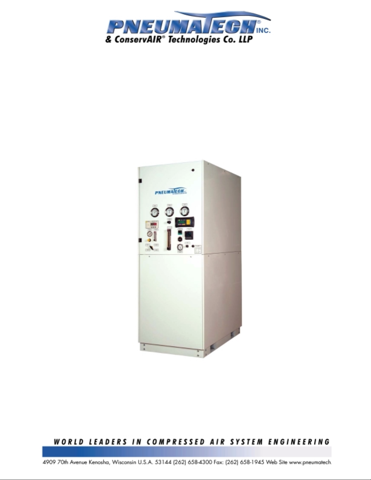
PMNG Cabinet Series
Membrane Nitrogen Generators
Installation, Operation & Maintenance Manual
Page 1 of 18
Page 2

Model PMNG-800HP – Serial No. 0210-G137961-034818
INSTALLATION, OPERATION, AND MAINTANANCE MANUAL
TABLE OF CONTENTS
1.O GENERAL
1.1 INTRODUCTION Page 4
1.2 SYSTEM DESCRIPTION Page 4
1.3 MODEL INFORMATION Page 4
1.4 SERVICE INFORMATION Page 4
2.0 SAFETY
2.1 GENERAL Page 5
2.2 BREATHING Page 5
2.3 COMBUSTION Page 5
2.4 PRESSURE Page 5
2.5 ELECTRICAL Page 6
2.6 ENVIRONMENTAL Page 6
3.0 INSTALLATION INSTRUCTIONS
3.1 GENERAL Page 6
3.2 LOCATION AND SETTING OF UNIT Page 6
3.3 ELECTRICAL SERVICE Page 6
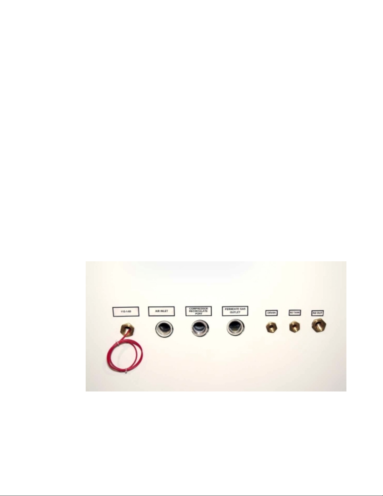
3.4 CONDENSATE DRAIN CONNECTIONS Page 6
3.5 NITROGEN PIPING CONNECTION Page 7
3.6 PERMEATE GAS CONNECTION P age 7
3.7 COMPRESSOR RECIRCULATION CONNECTION Page 7
3.8 COMPRESSED AIR INLET CONNECTION Page 7
3.9 NITROGEN TANK CONNECTION Page 7
3.10 ELECTRICAL SUPPLY CONNECTION Page 7
4.0 DESCRIPTION OF SYSTEM
5.0 PRE-START INSPECTION
6.0 INITIAL START UP and ADJUSTMENTS
6.1 NITROGEN SYSTEM SETUP Page 10
6.2 NITROGEN PURITY SAMPLING SYSTEM SETUP Page 10
6.3 ECONOMIZER ADJUSTMENTS Page 11
6.4 CRITICAL ADJUSTMENTS Page 11
7.0 OPERATING INSTRUCTIONS
7.1 GENERAL DESCRIPTION Page 11
7.2 OPERATION OF THE UNIT Page 11
1. MANUAL SYSTEM Page 11
2. AUTOMATIC SYSTEM Page 11
3. HEATER & CONTROLS Page 11
Page 5
Page 6
Page 8
Page 10
Page 10
Page 11
Page 2 of 18
Page 3

4. POWER-ON LIGHT Page 12
5. ON/OFF SELECTOR Page 12
6. PURITY VENT Page 12
7. MAIN FLOW METER Page 12
8. ECONOMIZER Page 12
9. ∆P SWIT CH/GAUGE & LIGHT Page 13
10. HOURMETER Page 13
8.0 OPERATION & MAINTENANCE
8.1 HEATER & CONTROLS Page 13
8.2 HIGH TEMPERATURE THERMOST AT Page 14
8.3 ROUTINE MAINTENANCE Page 14
9.0 ROUTINE MAINTENANCE SCHEDULES
10.0 RECOMMENDED SPARE PARTS
11.0 WARRANTY
Page 18
Page 16
Page 13
Page 15
Page 3 of 18
Page 4

1.0 GENERAL
f
y
y
t
t
1.1 INTRODUCTION -
instructions for the Pneumatech PMNG Cabinet Series membrane nitrogen generator. Please read
and be familiar with this manual before attempting to op erate the unit. Although this unit is very
simple to operate, the user will be working with high-pressure gas that must be handled with
caution. Compressed gas, if handled improperly, can result in serious or fatal injury.
This manual describes the installation, operating, and maintenance
1.2 SYSTEM DESCRIPTION -
hollow fiber semi-permeable membrane for the separation o
nitrogen and other gases from a compressed air stream. The
membranes divide the air into two streams; one is essentiall
nitrogen along with argon and traces of other inert gasses. The
other stream is oxygen plus carbon dioxide, hydrogen and other
trace gases. While fast gases such as oxygen, carbon dioxide
and water vapor quickly permeate the membrane surface, most
of the nitrogen flows inside the membrane fiber as a separate
product stream. Millions of fibers, about the size of a human
hair, can be packed into a single module. This provides a ver
large membrane surface area that efficiently produce large
quantities of nitrogen. This system is designed to deliver
nitrogen plus other inert gases at specified concentration.
Because water vapor is being permeated out of the gas stream,
the resulting atmosp heric dew point is -65°F or below.
A connection has been provided to pipe the permeate gases away from the unit. The system is
designed to operate with feed air from a plant compressed air system that has been dried to at leas
+40 degree F pressure dew point. The membrane modules are protected from hydrocarbons by a
highly efficient, six-step filtration system. This system consists of a combination of particulate,
coalescing filters and carbon adsorption. The result is air purity with a heavy hydrocarbon carryover a
or below 2 parts per billion.
1.3 MODEL INFORMATION -
NITROGEN GENERATOR
1.4 SERVICE INFORMATION -
MAINTENANCE OR REPAIR OF THE PMNG UNIT, CONTACT YOUR LOCAL
PNEUMATECH DISTRIBUTOR. CONTACT PNEUMATECH, INC. FOR THE
DISTRIBUTOR IN YOUR AREA.
The PMNG utilizes a
O
2
H2O Vapor
N
2
PNEUMATECH MODEL NO. PMNG-800HP-V01
FOR QUESTIONS CONCERNING THE OPERATION,
CO
2
Pneumatech, Inc.
4909 70TH Avenue
Kenosha, Wisconsin (USA) 53144
Phone: 262-658-4300 Fax: 262-658-1945
Page 4 of 18
Page 5

2.0 SAFETY
2.1 GENERAL -
2.2 BREATHING -
2.3 COMBUSTION -
2.4 PRESSURE -
This unit has electrical equipment and standard process plant components, which
can be hazardous to individuals unfamiliar with such equipment. It is the users’ responsibility to
permit only trained and qualified process plant operators familiar with the handling of compressed
gases to operate this equipment
This unit is designed to produce high purity nitrogen from 95-99.995% purity.
Nitrogen is a colorless, odorless gas that will not support life. If released in an unventilated area, it
will displace the oxygen and can cause injury or death from asphyxiation. A general indication of
what can potentially occur at depleted levels of oxygen is given below:
Oxygen Content - Effects and Symptoms
15-l9% Decreased ability to work strenuously. May impair coordination and may induce early
symptoms in persons with coronary, pulmonary, or circulatory problems. Note that at
below 15% oxygen content, personnel will require assistance from others to be
evacuated from the area.
l2-l4% Respiration increases with exertion, pulse rate increases, coordination is impaired, and
perception and judgement are also affected.
10-12% Respiration further increases in rate and depth, poor judgement, blueness of lips.
8-10% Mental failure, fainting, unconsciousness, ashen face, blueness of lips, nausea, and
vomiting.
4-6% Coma in 40 seconds, convulsions, respiration ceases, cardiac arrest, death.
CAUTION:
AN ENCLOSED OR POORLY VENTILATED AREA CONTAINING
NITROGEN GENERATION OR TRANSMISSION EQUIPMENT AND
PIPING, FOLLOW ALL ESTABLISHED SAFETY PRECAUTIONS AND
PROCEDURES.
Nitrogen gas represents an extreme asphyxiation hazard when not handled properly. Product
gas should not be vented or otherwise discharged except through the normal piping system.
Appropriate signs should be placed in the area of the nitrogen system warning of the hazards
typically contains 35%-40% oxygen, but can be as high as 45% oxygen. While oxygen will not
burn, oxygen concentrations above 25% will support combustion of other materials much more
readily than air.
atmosphere
unit is located in a poorly ventilated room, the waste gas must be piped to a ventilated atmosphere
for release.
The nitrogen product is then delivered to the user’s system at a pressure within 40 PSIG of inlet
pressure. Systems utilizing gas boosters for raising the pressure of the nitrogen product can operate
at pressures of 4500 PSIG and higher. Normal precautions for pressurized systems should be
observed during operation, service, or troubleshooting. Always isolate components that are to be
serviced, vent i ng pressure before disconnecting lines or dismantling components.
. It is imperative that vent gas be discharged only in safe, well-ventilated areas. If the
NITROGEN IS AN ASPHYXIANT. BEFORE ENTERING
.
The waste gas (permeate) vented out of the system is oxygen enriched; it
For example, materials that smolder in air could burn fiercely in this
The feed air pressure supplied to the generation unit can be as high as 200 PSIG.
Page 5 of 18
Page 6
2.5 ELECTRICAL -
The system utilizes three-phase and/or single-phase alternating current for
power and control. It should be protected with a disconnecting device as dictated by national and
local electrical codes. Ensure that the unit is connected to an adequate earth-ground before applying
power.
2.6 ENVIRONMENTAL -
The automatic drains for the entire system are connected to a single
header. These drains release collected oil and water. Because the condensate from this equipment
may contain oil, it must be disposed of properly. Oil concentrations in the water could be
approximately l50-200ppm.
3.0 INSTALLATION INSTRUCTIONS
3.1
3.2
3.3 ELECTRICAL SERVICE -
3.4 CONDENSATE DRAIN CONNECTIONS -
GENERAL -
installation. Since it is a packaged system, there are few connections to be made before the unit can be
placed into operation. A single point air inlet, electrical connection, condensate drain, and a final nitrogen
gas, nitrogen tank connection are required for a proper installation. If required, the waste gas (permeate)
can be piped away from the unit utilizing a singe connection.
LOCATION AND SETTING OF UNIT -
of supporting the static weight of the equipment. No special foundations or anchor bolts are required for
the installation but may be used at the discretion of th e customer. If the surface is not level, shims and
mounting bolts are recommended as a solution. Please contact Pneumatech, Inc. if a leveling problem
occurs during installation. The unit should be installed in a well-ventilated area where the ambient
temperature range will be between 40 and 104°F.
supply with an earth ground. All interconnect wiring has been provided.
utility end (back) of cabinet to connect to the floor drain or other disposal to pipe away oily condensate
from the system. Please note that it is normal to find oil in the condensate when feed compressor source is
of the lubricated type. (Refer to par. 2.6 Environmental.)
The Pneumatech PMNG Cabinet Series membrane nitrogen generator is d esigned f o r ease of
The unit should be installed indoors on a level surface capable
This machine requires a 120 volt, 1 phase, 60 Hertz, 20 ampere electrical
A ¼” NPT (F) bulkhead connection is provided on the
Page 6 of 18
Page 7

3.5 NITROGEN PIPING CONNECTION -
bulkhead connection on the utility end (back) of cabinet. No other check valves are required or
recommended beyond this point. An isolation ball valve is provided for field installation by others.
3.6 PERMEATE GAS CONNECTION -
(waste gases) away from the machine. (Refer to section 2.3 Combustion.) Note: If piped away from unit,
use a minimum size of 1”. For each ten (10) feet of piping, increase one pipe size with n o more than 50
feet in length is recommended to prevent back pressure. Back pressure to the membranes will reduce their
performance.
3.7
COMPRESSOR RECIRCULATION CONNECTION –
connection has been provided to pipe the waste gas from the second membrane or set of membranes, which
are connected in series. This line can be connected to the intake of a dedicated feed compresso r to improve
nitrogen generator efficiency. This line will contain 90-95% nitrogen. (Please refer to Section 2.2
Breathing) If not used with dedicated compressor, and the area is not ventilated well, this line should be
connected with the permeate line and d ischarged from the area.
The final nitrogen connection is made into a ½” NPT (F)
A 1” NPT (F) connection has been provided to pipe permeate
On optional High-Purity Systems a 1” NPT (F)
3.8 COMPRESSED AIR INLET CO NNECTION
– A 1” NPT(F) connection is provided for the feed
air inlet. An isolation ball valve is provided for field installation by others.
3.9 NITROGEN TANK CONNECTION
– A ¼” NPT (F) connection is provided for connection to the
nitrogen tank downstream of the nitrogen generator. This is to check purity in systems with oxygen
analyzers, and for sensing system pressure on systems with booster compressors.
3.10 ELECTRICAL SUPPLY CONNECTION
– A ½” NPT(F) connection is provided with flexible
conduit to the control box.
Page 7 of 18
Page 8
m
n
r
m
r
t
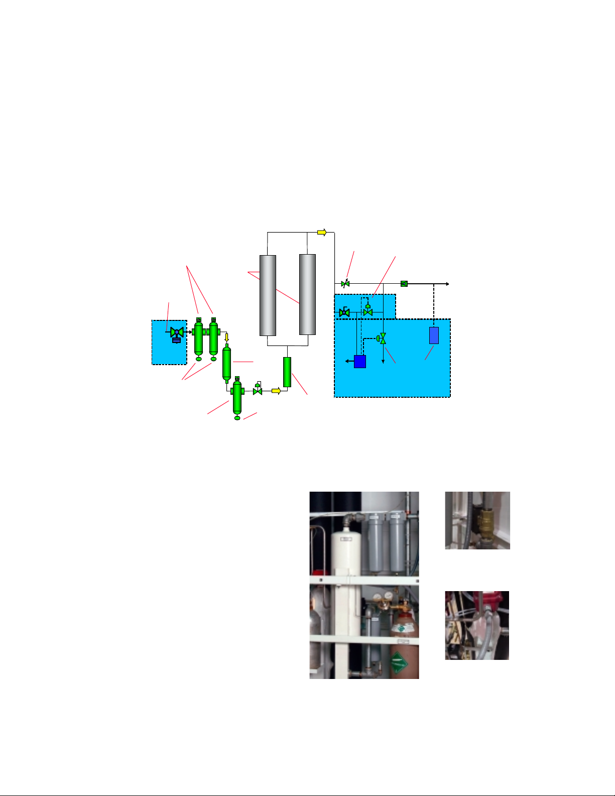
4.0 DESCRIPTION OF SYSTEM -
modular system consisting of pre-filtration, separation, and distribution sections. Controls for the
system are included in the nitrogen separation unit.
Ambient air enters the feed air compressor, which is typically an oil injected rotary screw air
compressor via its inlet filter. Air is compressed and travels thr ough an aftercooler and, in most
systems, a refrigerated air dryer.
COALSECING
COALSECING
FILTERS
FILTERS
AIR
AIR
IN LET
IN LET
ECONOMIZER
ECONOMIZER
VALVE
VALVE
DRAIN
Inside the PMNG nitrogen generation unit, the first ite
the feed air comes in contact with is an inlet isolatio
valve, which is shipped loose for installation in the field.
For systems with the optional EconoMizer™, an ai
actuated ball valve. Next is the 6-Step filtration system,
which utilizes a combination of particulate, coalescing
and carbon adsorption technologies. Oil carryover fro
system is expected to be in the 2 parts per billion range,
with maximum solid particle size .1 micron. All filters
are fitted with automatic condensate drains. The
optional panel mounted differential pressure switchgauge (if fitted) measures the filter system pressure drop.
If the pressure exceeds the 10 PSID setting a warning
message is displayed. Most units are fitted with the ai
circulation heater and controls, and is installed in the air
stream before the nitrogen membrane(s) but after the
final filter and pressure regulator. This heater maintains
a constant temperature of compressed air to the
membranes enhancing stability and performance.
Controls for the heater are installed on the instrumen
panel.
MEMBRANE N2SYSTEM
MEMBRANE
MEMBRANE
BUNDLES
BUNDLES
CARBON
CARBON
BED
BED
PARTI CLE
PARTI CLE
FILTER
FILTER
DRAIN
The PMN G Cabinet Series membrane nitrogen generator is a
MANUAL
HEATER
HEATER
MANUAL
PURITY
PURITY
CONTROLLER
CONTROLLER
OXYGEN
OXYGEN
ANALYZER
ANALYZER
OPTIONAL EQU IPMENT
AUTO
AUTO
PURITY
PURITY
CONTROLLER
CONTROLLER
NITROGEN
NITROGEN
VENT
VENT
P
S
ECONOMIZER
ECONOMIZER
PRESSURE
PRESSURE
SWITCH
SWITCH
EconoMizer™
2-Way Valve
6-Step Filtration
Heater
Page 8 of 18
Page 9
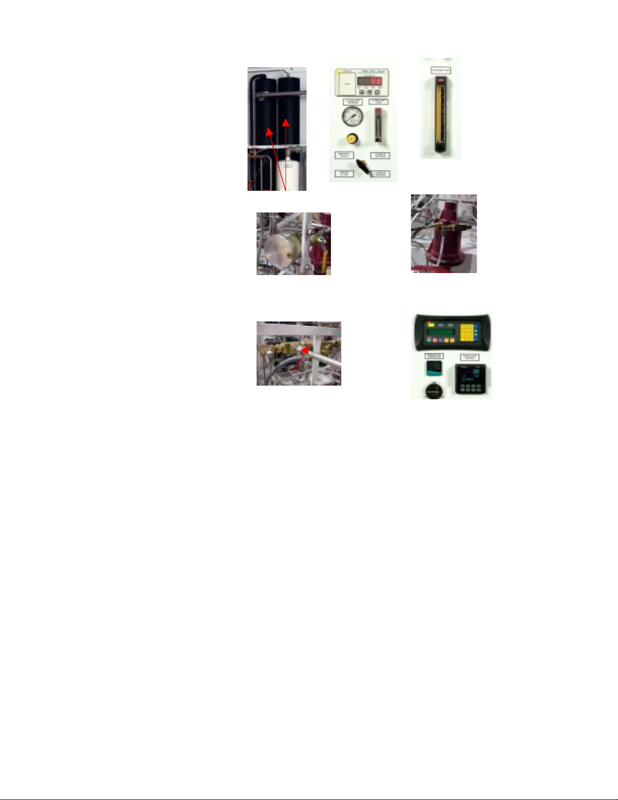
The nitrogen membrane module(s)
n
p
r
p
y
t
n
n
y
p
n
t
p
p
t
are located in the heated air stream.
On low purity multiple module
systems 99.5% and below, the
membranes are connected i
arallel. On high purity multiple
module systems 99.5% or higher,
they are connected in series o
combination of series and parallel.
High purity systems have separate
ermeate connections. One is
strictly waste gas, but the second
one is a line that can be re-circulated
Membranes
Oxygen Analyzer
System
Nitrogen
Flowmeter
back to the feed compressor intake
to enhance purity and productivity.
After the air passes through the
membrane bundle(s) it is essentiall
nitrogen plus trace amounts of iner
gasses and the specified oxyge
content. A built-in flow meter is
there to constantly monitor nitroge
Manual Flow Valve
AutoPure™
Valve
flow. Oxygen content (purity) is
controlled by a manual valve or b
the optional AutoPure™ automatic
urity/flow control system. If the
unit is fitted with the latter, it will
have a proportionally controlled
valve that gets its control signal
from a dual loop process controller.
The controller constantly monitors
the output signal from the oxyge
analyzer, comparing it to the se
oint (user selectable), and throttling
the automatic valve to match the
Non-Return
(Check) Valve
Operator Interface,
Temperature &
Purity Controllers,
Hour meter
urity level to the set point. After the
nitrogen passes this point it goes
through a non-return valve and ou
via the outlet isolation valve.
Page 9 of 18
Page 10

5.0 PRE-START INSPECTION -
1. Check that the electrical service matches the requirements listed in section 3.3 Electrical Service.
2. Check that the circuit breaker or fused disconnect and power cables are properly sized to meet the
machine’s amp rating.
3. Check that the unit has been installed according to the instructions in Section 3.0 Installation Instructions.
6. Check that there are no loose lines or loose wires.
6.0 Initial Start Up and Adjustment –
nitrogen generator be started and adjusted initially by a qualified technician. The following instructions are
presented for your information.
warranty may become void.
operator.
After initial start up, only minor adjustments should be necessary by the
6.1 Nitrogen System Setup
1. Remove the right upper side panel and slowly open the inlet ball valve until pressure is equalized
in the nitrogen system.
2. Listen for any air leaks. It will be normal to hear or feel gas escaping from the permeate and
compressor recirculation ports on the backside of the unit. Systems with EconoMizer™ will not
pressurize past 2-way valve until the Start button on the Operator interface is pressed. At this
time, a by-pass solenoid valve is energized to slowly pressurize the system. There is an adjusting
valve that controls how fast the system will reach pressure. Adjust valve so the system
pressurizes in 30-45 seconds.
3. If equipped with oxygen analyzer, its display should be illuminated at this time. On systems with
Heater and/or AutoPure™ Options, their displays will energize only after units reach full
pressure.
4. Press the Start button on the operator interface on the front gauge panel.
5. Adjust needle valve on re-pressurizing circuit to pressurize system between 30 & 45 Seconds
after pressing run button (units equipped with EconoMizer™)
6. The heater controller and the purity controllers should be making their self-adjustments.
7. Calibrate oxygen sensor as described in 6.2 below.
8. Observe the nitrogen membrane pressure gauge and the inlet air pressure gauge. Adjust the
membrane pressure regulator to 15 PSIG below the lowest expected supply pressure. Turn
clockwise to increase turn counterclockwise to decrease pressure.
6.2 Nitrogen Purity Sampling System Setup
1. If unit is equipped with the optional oxygen analyzer, make sure the analyzer is calibrated before
using the generated nitrogen. High purity systems utilize gases which are calibrated at a known
oxygen content to calibrate othe oxygen analyzer. The trace oxygen (PPM O2) utilizes a two
point calibration (high range and low range). The 5-way valve located under the analyzer on the
front panel allows for sensing the gas from four locations; two of which are the Calibrate High
and Low Span Gas Positions. Calibrate with the High Span first and then repeat using the Low
Span.
contents in between calibration intervals.
2. Make sure the Purity Sampling System is properly set so that damage to the oxygen analyzer does
not occur and proper readings can be obtained.
3. There should be no valve on the discharge of the sensor. The sensor is designed to operate at or
near atmospheric pressure.
4. There are two pressure regulators on the high purity system. One is located inside the cabinet
behind the panel mounted regulator. Set the one inside the cabinet at 30-40 PSIG. Adjust the
Valve on the Span Gas tanks should be closed when not in use to avoid loss of
Note:
Before attempting to start the unit check the following:
It is recommended that your cabinet series high purity membrane
CAUTION: If users readjust certain components, part or all of the
Over pressurizing can damage the sensor.
Page 10 of 18
Page 11

analyzer pressure regulator on panel until the flow reaches 2-3 SCFH by pulling out on the yellow
knob and turning clockwise to increase, and counter-clockwise to decrease pressure or flow rate.
5. The needle valve on the oxygen sample flow meter should be turned counter clockwise to open
fully. A change in main regulator set pressure may require re-adjustment.
6. Allow oxygen content reading on display to stabilize.
7. Press Mode Button until “CAL” appears in display. After releasing button, the display will
indicate an oxygen content. Press !keys to make the display agree with the Span Gas content.
8. Process may need to be repeated to fine tune.
9. When calibrated, Press MODE Key until RUN is displayed. Release MODE button.
10. Once the display settles in agreement with the span gas contents, the unit is calibrated. Switch
the 5-Way valve to the “Monitor N2 Outlet” position.
6.3
6.4 Critical Adjustments –
EconoMizer™ Adjustments – If system has been equipped with an energy saving EconoMizer™
control system, there are field adjustments necessary to proper operation.
There are certain settings and adjustments that should not be tampered
with. If these are re-adjusted without written consent of Pneumatech, Inc., all or part of the warranty
on the unit may become void.
These are the as follows:
1. Heater controller is factory adjusted for from 70-105 degrees F and should not be re-adjusted
above 110 degrees or membrane performance can decline over time. Temperature in excess of
125 degrees F will damage the membrane material.
2. High temperature safety switch has been factory set at 120 degrees and should not be re-adjusted.
3. A membrane inlet pressure switch is supplied with all units with the heater option. If pressure is
on the system there will be airflow to the heater. The pressure switch is factory set to
approximately 85-90% of the inlet pressure and should not be re-adjusted unless the inlet pressure
to the membrane is re-adjusted.
7.0 OPERATING INSTRUCTIONS
7.1 GENERAL DESCRIPTION -
system that is factory assembled, tested, and ready for service. The system requires connection to the
user’s system as described in Section 3.0.
7.2 OPERATION OF THE UNIT –
user needs to follow the instructions in section 6.1, paragraphs 1,2 & 8.
1.
Manual System
discharge manifolds, needs to be adjusted so that the system delivers the specified flow rate using
built-in flow meter.
2.
Automatic System
to be adjusted. This is done on the purity controller by pressing the ! [up or down arrow] keys to
reach the desired oxygen content. All other settings in the controller have been factory set and do
not require further adjustment. The purity set point has been factory set as called out in either the
purchase order or job specifications. There is a manual by-pass valve in the event that servicing
needs to be done to the automatic valve. Simply close the isolation ball valves that supply the
automatic valve and open the ball valve that isolates the manual flow controller. If the manual
controller has been preset to the necessary flow rate or oxygen content at start-up, no further
adjustments are necessary. A small set screw adjusts the flow and uses a 3/32” allen wrench.
3.
Heater & Controls
performance and operates automatically. Adjustments outside the specified temperature range will
– On manually controlled systems, a flow controller, located between the nitrogen
– On automatically controlled systems, only the oxygen content set point needs
Pneumatech Model PMNG Series nitrogen gas generator is a complete
– If the unit is supplied with a heater, it has been factory set for optimum
The basic standard system is manually controlled. In this system, the
Page 11 of 18
Page 12

affect warranty. Instructions are given for adjustment in section 9, if for any reason the controller
must be replaced or re-adjusted.
4.
On/Off Selector Switch
Interface), the panel will have an On/Off selector switch to start & stop the system. The unit will
requires pressure on the system before the heater will run. Systems with Operator Interface, have a
Power OFF/On switch.
5.
SurePure™ Purity Vent
product gas meets the required purity. Unit is shipped factory set as called out in either the
purchase order or job specifications. If unit is supplied with the automatic purity vent the user can
adjust the HI Alarm (Alarm 1) on the oxygen analyzer to dictate when the generator is within
acceptable limits on delivered oxygen content. Simply, press the Mode button on the oxygen
analyzer and toggle until Alarm 1 appears. Press the [Up Arrow] or [Down Arrow] key until the
desired setting. Press the Mode button repeatedly until “Run” appears. In approximately 2 minutes,
the unit will go back to normal. The setting must be greater than the purity controller set point as
described in section 7.2, paragraph 2 above.
6.
Main Flow Meter
panel mounted.
7.
Economizer
tank downstream of the generator unit. The purpose of this option is to save energy and run time on
the unit during times of lo w or no demand. T here are hi gh (PS2) a nd low (PS3) pressure switches
to be set. The low-pressure switch (PS3) should be set slightly above the minimum acceptable
pressure to allow at least 5 minutes of operation from storage. This can be calculated using the
following formulae.
– If the unit is supplied with this option, the system will also have a nitrogen storage
MPsMPP =+∆
MPs
= Minimum Pressure Setting o f PS3
P
∆
= Pressure difference between
Storage
7.14
×
– If the unit is supplied with heater and controls, (but no Operator
– This is a system that will vent off-spec nitrogen to at mosphere until the
– Each unit is equipped with a nitrogen flow meter and on cabinet systems is
Where: MP = Minimum Pressu re
MPs
& MP
∆=
P
Where:
Storage
= Rate x Minutes
V
14.7 = Atmospheric pressure (PSI)
Rate = Maximum demand flow rate in SCFM
SCFM = SCFH ÷ 60
V = Volume in Standard Cubic Feet (SCF)
SCF = Tank volume in gallons ÷ 7.4805
Example:
You have a minimum pressure requirement of 40 PSIG, a 1060-gallon tank, and a maximum
demand of 450 SCFH. Calculate the minimum pressure setting.
1. Solve for SCFM (450 ÷ 60) = 7.5 SCFM
2. Solve for SCF (1060 ÷ 7.4805) = 141.7 SCF
3. Solve for Storage (7.5 SCFM x 5 minutes) = 37.5 SCF of Storage
7.145.37
4. Solve for ∆Ρ
×
PSID
9.3
=
7.141
5. Solve for MPS (40 PSIG + 3.9 PSID) = 43.9 PSIG minimum switch setting.
The low-pressure switch (PS3) should never be equal to or greater than the setting of high-pressure
switch (PS2). In fact, it should be at least 10 percent lower to avoid control problems due to drift of
the pressure switches.
The high-pressure switch (PS2) should be set at least 25 PSIG below the minimum required inlet
pressure to the unit to allow fo r pressure drop thr ough the unit due to normal pressur e drop and
filter particle buildup.
Page 12 of 18
Page 13

8. ∆∆∆∆ΡΡΡΡ
9.
Gauge & Message
whenever the differential pressure exceeds the setting on the switch. This switch is factory adjusted
to approximately 10 PSID and should not require adjustment. A light will illuminate along with a
message to alert the operator that the filter elements need changing.
Hourmeter
hour meter does not run when the economizer is active. The pressure switch (PS1) controls when the
hourmeter runs.
– The hour meter will be energized any the generator is actually making nitrogen. The
8.0 Operation & Maintenance
8.1 Heater Controls
A. Initial Setup
With unit pressurized and On/Off Switch in the on position, locate the CAL controller on the
electrical enclosure door. Upon power up a new controller will need to be programmed. Initially
it will display “
1. Input Type
Initially “
release the buttons. Press " once and the display will now read “
2. Select Units
Press and hold * and press"#keys to locate
the display will now read “
3. Setpoint Device
Press and hold * and press"#keys to locate
4. Save to Memory
Press and Hold "#keys simultaneously for 3 seconds to enter initial configuration into
controller memory. The display will now read “
entered yet..
inPt : none
inPt : none
B. Auto Tune
1. Set Temperature
Press the * and " until the temperature set point is about 15 degrees above the upper display
reading to allow autotune to perform properly.
2. Tune
Press the "#keys simultaneously for 3 seconds and “Tune” should appear in the display.
3. Tune at Setpoint
Press * and " until tune:At.SP appears Press "#keys simultaneously for 3 seconds. Unit
will auto tune to proper setting. If auto tune does not give desired results, PID values can be
input manually using the following procedure.
C. Manual Tuning
1. Enter Tuning
Press the "#keys simultaneously for 3 seconds and “Tune” should appear in the display.
2. Proportional Band
Press the " key until
3. Integral
Press the " key until
4. Derivative
Press the " key until
D. Temperature Setpoint
Press and hold the * and "# until the lower display reaches the desired temperature set point.
Release keys and the new setpoint is established.
– If unit is supplied with this option, the filter elements can be changed
”
” is displayed. Press and hold * and press"#keys to locate
unit : none
o
and release the buttons. Press " once and
F
SP1.d : none
Auto Tune needs to be performed before the final set point is entered.
appears. Hold the * and " keys until a value of
bAnd
appears. Hold the * and " keys until a value of
int.t
appears. Hold the * and " keys until a value of
dEr.t
”.
SP1.d:SSd
ParK”
and release the buttons.
because a setpoint has not been
tC K
”.
is reached.
5.8
is reached.
4.5
is reached.
16
and
Page 13 of 18
Page 14

8.2 High Temperature Thermostat
A. Initial Setup
Press SET key once to get to Units
B. Set Units
o
Press the "key until
is displayed. Press SET key once to get to Setpoint Temperature.
F
C. Setpoint Temperature
A small “blinking” S1 will appear in the upper left of the display. Press the "#keys to advance
to the desired setpoint of 120 degrees F. Each press of the key will advance one degree. Press the
SET key once to get to the Differential Temperature Mode.
D. Differential Temperature
A small “blinking” DIF1 will appear in the middle left of the display. Press the "#keys to
advance to the desired differential of 5 degrees F. Each press of the key will advance one degree.
Press the SET key once to get to the Heating/Cooling Mode.
E. Heating Mode
C1 or H1 will appear in the display. Press the " key until H1 is displayed. Press the SET key
once to get back to the monitoring mode. Programming is now complete.
8.3 Routine Maintenance
A. Isolate Unit
1. Disconnect Power to the Unit
2. Close isolation valves (customer mounted ) and allow pressure to vent off the system.
B. Change Filters
1. Unscrew the housing from the filter head and drain off any oil in the housing into a suitable
container. Stuff clean rag into filter bowl to keep unit clean while changing the elements.
2. Unscrew the locking nut on the bottom of the element and discard the element. Replace the
element with a new one of the appropriate grade and replace the locking nut. Do not over
tighten..
3. Auto drain – Each filter is fitted with an internal automatic float drain to carry away
condensate (water & oil). There should only be a small amount of liquid in the housing. As
the level of the oil increases, the float rises and discharges liquid from the housing. If a large
amount of oil is found, remove the auto drain, clean or replace.
4. Replace Filter housing. After replacing the element, remove the rag and screw the housing
back on to the filter head. Do not over tighten. Housing is sealed with an o-ring, so gently
hand tighten.
5. Repeat this process for all three (3) filters.
C.
Change Carbon -
vessel will need to be removed from the machine to re-fill with carbon.
1. Disconnect the union fittings at the top and bottom of the housing.
2. Remove the bolts in the mounting brackets (floor and side brace) that hold the vessel in place
and remove the vessel from the unit.
3. Unscrew one of the screens from either end (3/4” nipple) to allow access to the carbon. Take
precautions to not damage the threads. Drain the carbon into a container and replace with
fresh BM-000427 carbon.
4. Replace screen.
5. Re-mount the vessel, connect the piping and secure.
6. Unit is now ready to put back on line.
Once per year or every 4000 hours, replace the carbon in the carbon vessel. The
Page 14 of 18
Page 15

9.0 ROUTINE MAINTENANCE SCHEDULE
Daily
1.
2. Check for air and nitrogen leaks. Tighten or re-tape fittings as necessary.
3. Check that the Membrane Inlet pressure is as established upon setup of the equipment
4. Check that the inlet air temperature is less than 105°F and pre-cool if necessary.
5. Check that hour meter (if equipped) is operative.
Weekly
1. Clean unit as necessary.
2. Check that the differential pressure on the filtration system does not exceed 10 PSID. The filter
elements need to be replaced when differential pressure reaches 10 PSID.
Every three months
1. Check operation of all safety relief valves
2. Calibrate oxygen sensor (if equipped) See section 6.4
Annually or longer intervals
1. Replace all filter elements on the unit at 8000 hours. If the unit is equipped with differential
pressure switch/gauge, the filter elements should be changed at 10 PSID.
2. Change the carbon in the carbon adsorber bed. Units with a functioning hourmeter can run for
8000 hours before changing carbon.
3. Every three - five years, return oxygen analyzer for factory sensor replacement and re-calibration.
Page 15 of 18
Page 16

10.0 SPARE PARTS
Spare Parts – PMNG-800HP Nitrogen Generator – SN:
QTY REFERENCE Part # DESCRIPTION
2 Filter 1 (4), Filter 3 (7) Q-095-15 Coalescing Filter Element, Pre-filters No. 1 & 3 1 2
1 Filter 2 (5) C-095-15/G4 Coalescing Filter Element, 2nd stage pre-filter 1 1
18 Carbon Tower (9) BM-000427 Air separation grade carbon (lbs.) 1 18
1 SV4 (38) VA-001822 Solenoid Valve,.5"NPT,N.O.,200PSI,120V 2 1
2 SV2 (25,39) VA-000131 Solenoid Valve,.5” NPT, N.C., 300PSI,120V 2 1
2 Membrane (19) RG-002672 Membrane, Nitrogen 3 0
1 PLC EC-000024 PLC, 10 AC In, 8 Relay Out, 120VAC 3 0
1 Operator Interface EC-000018 Panel, Operator Interface, EZ-220P 3 0
1 Cable EC-000019 Cable, PLC-Panel, EZ-2CBL 3 0
4 Regulator (31) VA-000807 Regulator, .125” 3 0
1 Relief Valve (6) VA-001531 ASME safety valve, 1/4", 150 PSI, 2 1
1 Heater (13) RG-000419 Circulation heater,.75 kW, 120-1-60 3 0
1 Check Valve (26) VA-002870 Check Valve,.5",EPR Seat 2 1
1 SSR 1 EC-001771 Solid State Relay, 25 AMP 2 1
1 1FU EC-002718 Fuse, 15 Amp, 250V, Glass 2 1
1 HC EC-001769 Heater Controller 3 0
1 APC EC-003865 Automatic Purity Controller, Dual Loop 3 0
1 AV (24) VA-003004 Automatic Purity Control Valve 3 0
3 PS1, PS2, PS3 EC-001962 Pressure Switch 2 3
1 DPG-PS4 GM-000503
3 Press Gauge (2,18,36) GM-000497 Gauge, 0-200 PSIG, 3.5” Dia., Panel Mount 2 3
1 Reg-Pilot (11) VA-000547 Precision Regulator, Pilot, .25”, CR200H 3 0
1 Flow Valve (22) VA-003013 Controller, Flow, Manual, .25” NPT 3 0
1 Regulator (12) VA-000566 Regulator, Pilot Operated, 1” 3 0
1 BV-1” (1) VA-000986 Valve, Ball, 1” NPT 3 0
3 BV-.25” (23) VA-000002 Valve, Ball, .25” NPT 3 0
1 BV-.5” (27) VA-000971 Valve, Ball, .5” NPT 3 0
1 TC (17) GM-000253 Thermocouple, 2.5” Stem, 5Ft PVC wire 2 1
1 TC Fitting (17) 2-2FH4BZ-B Thermocouple Fitting 2 1
1 TS1 (16) EC-002372
1 C1 EC-002598 Contactor, 20 AMP, Heater 2 1
1 SV3 (35) VA-001411 Valve, Solenoid, 3-way, Economizer 2 1
2 Needle Valve (21) VA-000086 Valve, Needle, .5” NPT 3 0
1 2FU EC-002612 Fuse, 2 AMP 2 1
10 3-4 FU, 6-12 FU EC-000280 Fuse, .5AMP, 250V, Glass 2 10
1 Regulator (29) VA-002864 Regulator, Pressure, 5000 PSI,0-250PSI, .25” NPT 3 0
1 5FU EC-002411 Fuse, 1 AMP, 250V,Glass 2 1
1 GND EC-002705 Ground Bar, 4-14 3 0
1 Flowmeter (20) GM-000759 Flowmeter, 0-130 SCFH 3 0
1 Flowmeter-O2 (32) GM-000535 Flowmeter, .5-5SCFH, with SS Valve 3 0
1 BV-1”/Act (3) VA-002828 Valve, Ball, Brass, 1” NPT, with Actuator 3 0
1 SV1 (44) VA-001409 Valve, Sol, 4 Way, .25” 2 1
Gauge, ∆P Switch-Gauge, 0-15 PSID
Thermostat, Sensor, 1-stage, -30-225°F
0210-G137961-034818
Stock
Level
3 0
3 0
Rec.
QTY
Page 16 of 18
Page 17

SPARE PARTS (Continued)
Spare Parts – PMNG-800HP Nitrogen Generator – SN: :
QTY REFERENCE Part # DESCRIPTION
1 HM EC-002082 Meter, Hour, 115-1-60 2 1
1 O2 (33) EC-004065 Analyzer, Oxygen, Trace (ppm) 3 0
1 PI-42 (42) GM-000041 Gauge, Pressure, 0-160, 1.5”, .125” NPT 2 1
1 BV (28) VA-002156 Valve, Ball, Brass, .125”, 5-Way, Panel Mnt. 3 0
1 24VDC CA-000264 Power, Supply,24VDC, .75 Amp 3 0
1 SW-1 EC-001634 Power OFF/ON Switch, 2-Position,Toggle 3 0
1 SW-2 EC-000180 PLC OFF/ON Switch, 2-Position,Toggle 3 0
1 CR1 EC-001038 Relay, 3-Pole, 120V 2 1
1 EC-000973 Relay, Socket 2 1
1 EC-000591 Clamp, Relay 2 1
1 I/P Transducer (45) EC-003066 I/P Transducer, 4-20mA 2 1
1 DP Trans. (37) EC-003866 Differential Pressure Transmitter, 4-20mA 2 1
3 Auto Drain RF-001281 Float Drain, Internal (Kit) 2 1
2 Filter Complete P4Q-095-15/F001-F002 Filter 1 & 3 complete 3 0
1 Filter Complete P4C-095-15/G4-F001 Filter 2 Complete 3 0
1 Screen (10) RG-002811 Screen, Carbon, 3 0
1 Thermowell EC-002068 Thermowell, Assy 3 0
0210-G137961-034818
Stock
Level
LEGEND FOR SPARE PARTS
QTY – Actual Quantity in System
REFERENCE – Elect. Schematic Reference or Brief Description
STOCK LEVEL 1 – Routine Maintenance (Recommended Spares)
STOCK LEVEL 2 – Repair Parts-Short Term (Optional Spares)
STOCK LEVEL 3 – Replacement Parts-Long Term
REC. QTY – Re commended Stock Level
Rec.
QTY
Page 17 of 18
Page 18
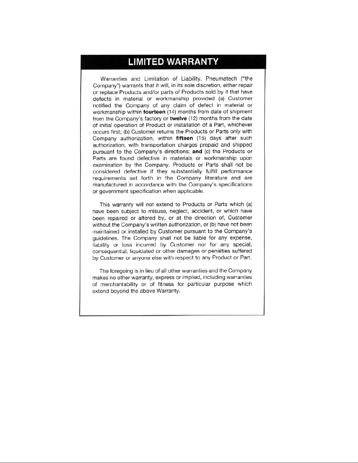
11.0 WARRANTY
Page 18 of 18
 Loading...