

Page 1

Heatless Regenerative Air Dryers
PHM Series / PH Series / EH Series
Owner’s Manual
9829 2103 75 May 2009
Page 2

DATE OF PURCHASE
MODEL
SERIAL NO.
Record above information from nameplate.
Retain this information for future reference.
1
Page 3

TABLE OF CONTENTS
General Information 4
Receiving – Inspection 4
Safety Instructions
Disclaimer of Warranty
Desiccant Replacement Procedures 6
Filling Procedure 6
Molecular Sieve Option
Draining Procedure
Desiccant Disposal 6
Installation & Operation 7
PH/EH Series Heatless Air Dryer Installation & Operation
General 8
Start-Up Procedure 8
Adjustments 9
DMP Microprocessor Control with Cycle Sight ™ 9
Sequence of Operation 10
Shutdown Procedure 11
PHM Mini Series Heatless Air Dryer Installation & Operation
General 13
Theory of Operation 13
Start-Up Procedure 13
Operational Observation 13
Maintenance 14
PH/EH Series Heatless Air Dryer Maintenance
General 14
Daily 14
Weekly 14
Monthly 14
Three Months 14
Twelve Months
Dewpoint Sensor (Optional) 14
Mufflers
PHM Mini Series Heatless Air Dryer Maintenance
General
Daily 15
Weekly 15
Three Months
Twelve Months 15
Mufflers
Desiccant Replacement Procedure 15
Desiccant Disposal
]
4
5
6
6
14
14
15
15
15
15
2
Page 4

Dewpoint Display Key Functions 17
Setting Point and Programming 17
Measurement Range 17
Options Listing with Explanation (PH & EH Only) 19
Audible Alarm 19
Failure to Shift Alarm 19
High Humidity Alarm 19
Moisture Indicator 19
Panel Lights 19
PLC Controller 19
Dewpoint Demand Control “DPD” 19
Troubleshooting 20
3
Page 5

GENERAL INFORMATION
The Pneumatech Drying System is designed to remove
moisture from compressed air.
When properly installed, the unit requires little
maintenance or adjustment.
A list of service parts is provided on the attached parts
list.
WARNING
DO NOT install, operate, maintain, adjust or service
this unit without thoroughly reading this manual.
This manual contains important safety information. Read
THOROUGHLY and follow the Safety Instructions
provided in this manual and posted on the unit. Keep this
manual near the unit and in a safe place. Replace this
manual if it becomes torn or dirty and cannot be properly
used.
Please read the Installation & Operation section of this
manual before attempting to operate the unit.
Please read the Maintenance and Troubleshooting
sections of this manual before beginning any
maintenance or service work on this unit.
RECEIVING – INSPECTION
Inspect equipment. Any concealed shipping damage
must be reported to the carrier immediately. Damage
claims should be filed by the consignee with the
carrier.
All the equipment shipped F.O.B. Kenosha, WI becomes
the property of the purchaser. In all cases of damage,
visible or suspected, contact your local distributor or
Pneumatech before attempting to install equipment.
SERVICE INQUIRIES: Provide Model No., Serial No.,
Operating Pressure, Inlet Temperature, Nature of
Problem. See Dryer Specification Tag located on the
control panel.
SAFETY INSTRUCTIONS
When using air compressors and compressed air
accessories, basic safety rules and precautions must
always be followed, including the following:
1. READ ALL INSTRUCTIONS FULLY.
2. WIRING & BREAKERS
Wiring, breakers and other electrical equipment must
conform to local and national electrical codes. Do
not operate this unit with damaged wiring or after the
unit or air handling parts have been dropped or
damaged in any manner. Notify authorized service
facility for examination, repair or other adjustments.
WARNING
Comply with the National Electrical Code, Federal,
State and Local Codes when installing or operating
this unit.
3. USE SUITABLE PARTS & ACCESSORIES
Do not use air pressurized accessories or parts in
the air system not suitable for the maximum air
pressure used. Be sure maximum pressure specified
by the accessory manufacturer is well above the
working pressure of your compressor.
4. RELEASE AIR PRESSURE SLOWLY
Fast moving air will stir up dust and debris, which
may be harmful. Release air pressure slowly when
depressurizing your system to avoid bodily injury.
4
Page 6

5. SECURE DRAIN LINES
Fasten drain lines from prefilter/separator to floor or
drain. Pressurized air will periodically pass through
drain lines, which will cause an unsecured line to
whip and may cause bodily injury.
WARNING
Air from compressor and from air drying system, as
equipped, is not safe for human respiration
(breathing).
To provide safe, breathable air, compressor must be
capable of producing at least Grade D breathing air as
described in Compressed Gas Association Commodity
Specification G7.1-1966. Special filtering, purifying and
associated alarm equipment must be used to convert
compressed air to “Breathing Air.” Other special
precautions must also be taken.
Refer to OSHA 29 CFR 1910.134.
DISCLAIMER OF WARRANTY
If this unit is used to produce breathing air, the special
equipment and precautions expressed in OSHA 29 CFR
1910.134 for specifications of the necessary equipment
and special precautions to make Breathing Air MUST BE
used or any warranties are VOID and manufacturer
disclaims any liability whatsoever for loss, personal
injury or damage.
CAUTION
Connect oil coalescing prefilter with automatic drain
before the dryer to prevent any oil or slugs of water
carryover into the desiccant. Connect particulate
afterfilter downstream of the dryer to retain any
desiccant dust flowing into the process air lines.
5
Page 7

DESICCANT REPLACEMENT PROCEDURES
Pneumatech uses Activated Alumina Grade A desiccant
for all standard heatless air dryers. Dryers up to 1500
SCFM are factory filled with desiccant. Dryers 1800
SCFM and larger are supplied with loose desiccant in 50
lb. bags. The dryer must be filled with desiccant before
start-up. Dryers ranging from 5 SCFM to 500 SCFM use
1/8" diameter desiccant. Dryers 650 SCFM and larger
use a mix of 1/8” and 1/4" size desiccant. See the dryer
specification sheet or dryer data tag for amounts per
tower.
FILLING PROCEDURE
For PHM models refer to Page 15.
1. Make sure the dryer is depressurized.
2. Remove the plugs or flanges from the fill ports
located on the top of the pressure vessels.
3. Using a flashlight, inspect the inside of each vessel
to be sure they are empty.
4. Verify that the desiccant drain port located in the
bottom of the pressure vessel is closed tightly.
5. Desiccant is available in 50# bags, or 300# barrels.
Divide the desiccant into equal amounts for each
tower, and verify the correct amount by the
specification tag located on the electrical panel.
Towers can be filled manually with desiccant bags.
A fork lift or overhead crane should be used when
filling with 300# barrels.
6. Dryers 650 SCFM and larger use two sizes of
desiccant. For all heat reactivated models, fill the
tower with the 1/4" diameter Activated Alumina first,
followed by 1/8" Activated Alumina. The large
desiccant (1/4” size) is used to disperse the inlet air
flow.
7. Close the fill ports and put the dryer in service. Refer
to the Start-Up Procedure listed in this manual.
MOLECULAR SIEVE OPTION
(LOW DEWPOINT)
Dryers with optional Molecular Sieve are filled with the
Activated Alumina first and the Molecular Sieve last.
The Molecular Sieve is used as a polishing agent to
lower the dewpoint temperature.
NOTE: The proper amount of desiccant may or may not
fill the vessel to the top.
DRAINING PROCEDURE
The desiccant can be removed by the two methods
listed below. MAKE SURE THE DRYER IS
DEPRESSURIZED PRIOR TO REMOVING THE FILL
OR DRAIN PORT.
Method #1 – Remove the drain port and drain the
desiccant into buckets which are then poured into the
proper dumpster or receptacle.
Method #2 – Usually used for large dryers (1000 SCFM
and larger). An industrial dry vacuum cleaner is required
for this method.
1. Remove the desiccant fill port.
2. Using an industrial vacuum cleaner, remove the
desiccant from the vessel.
3. Open the desiccant drain port and remove the
remaining desiccant.
DESICCANT DISPOSAL
Desiccant is not considered a hazardous waste, unless
contaminated with oil or other toxic substances. Disposal
of the desiccant should be handled by a local waste
management company.
6
Page 8
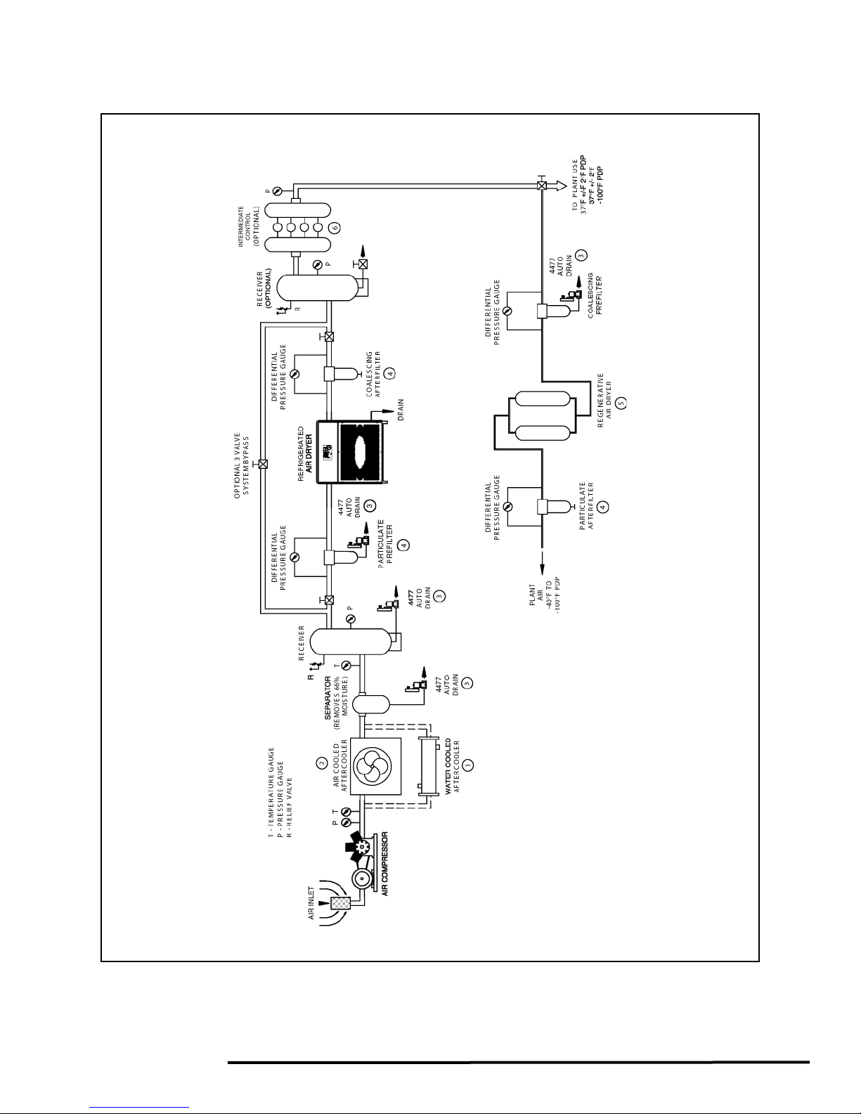
INSTALLATION & OPERATION
FIGURE 1 — COMPRESSED AIR SYSTEM RECOMMENDE
7
D INSTALLATION FLOW DIAGRAM
Page 9

PH/EH SERIES HEATLESS AIR DRYER
INSTALLATION & OPERATION
General
1. Install dryer on a level base, indoors or under a
shed.
2. During shipment, flange and connecting bolts can
come loose. All bolts should be checked and
tightened as needed.
3. Make sure when the piping is in place that no undue
stress is placed on dryer connections. Union joints
or flexible connections are recommended to relieve
stress. Also, properly support the pipes as needed
with hangers or brackets. Air piping must be
installed by an experienced pipe fitter.
4. Equip dryer with inlet and outlet isolation valves and
a bypass valve for ease of servicing and start-up.
5. Connect electric power to the dryer through a
properly sized fused disconnect switch.
6. Reactivation exhaust may be piped away from the
dryer, making sure proper pipe size is used. The
pipe size should be increased by one size at the
valve, and one additional pipe diameter size for
every ten-foot run to reduce back pressure.
7. ELECTRICAL CONNECTIONS: Follow the
recognized local and municipal electrical codes. All
components must be load rated as approved by
NEC, NEMA, CSA and UL.
DANGER
High voltage could cause death or serious injury.
Disconnect all power supplies before installing or
working on electrical components.
8. During shipment, wire connections may become
loose. Per U.L. specification, torque screws inside
enclosure to 20 in-lbs.
9. GROUNDING: It is mandatory that the dryer be
grounded. Use an adequate ground with the
conductor sized to NEC.
10. STORAGE: In case of extended storage period
before the installation, follow these simple
procedures:
a. Seal or cover all the parts
b. Wrap the electrical enclosure
c. Wrap the mufflers
d. If the desiccant is shipped loose, store it inside
to avoid any rain or water damage.
11. LEAK TEST: All the dryers are tested at the factory
for any leaks before shipment. An air leak could
develop during transportation or installation.
Pressurize the system and check fo r any leaks.
Start-Up Procedure
1. Keeping the dryer isolation outlet valve closed,
slowly pressurize both the adsorbent chambers to
the line pressure.
2. Check for any leaks in the system.
3. When both adsorbent chambers are at line pressure,
push the ON button.
4. One inlet valve will close, and one purge valve will
open and depressurize one adsorbent chamber.
This may take as long as 3 minutes.
5. Adjust the purge pressure to the recommended
setting, and lock the valve locking mechanism in
place.
6. Slowly open the dryer isolation outlet valve to
pressurize the downstream system.
7. Observe the dryer operation through one or two
complete cycles.
Adjustments & Settings
1. Adjust the purge pressure to the recommended level
____________PSIG.
2. Dewpoint Demand Setpoint: ______________
High Humidity Alarm Setpoint: _____________
(See dewpoint display settings on Page 17)
DMP Microprocessor Control with Cycle
Sight ™
For standard PH & EH Series Air Dryers.
INTRODUCTION
1. GENERAL: The DMP controller is a microprocessor
controlled, seven (7) channel sequence timer with
LED display features. The DMP controller consists of
the main control unit and a remote LED and timer.
8
Page 10
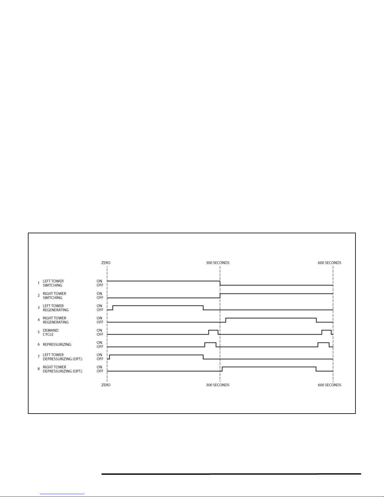
2. SEQUENCE OF OPERATION: The sequence of
operation is based on a five (5) minute or ten (10)
minute NEMA Cycle. For either cycle length, onehalf of the total time is for adsorption of moisture
from the process gas and one-half is for desiccant
regeneration. Specifics of the timing sequence are
detailed in Figure 2, the Sequence of Operation
Diagram (SDG-2). If power is interrupted and then
reapplied, the DMP controller will start the timing at
zero. At all times during operation, the current status
of the timing cycle is indicated graphically by the
LEDs.
3. FEATURES
drying/regenerating, demand cycle indicator
(opt.), high humidity alarm (opt.), fail to shift
alarm (opt.).
• 5 or 10 minute NEMA cycle selector
• Alarm reset button
MODE OF OPERATION
1. START UP: The Digital Microprocessor Sequence
Controller will start to operate as soon as the unit is
turned on. The load outputs will recycle on and off
based on a five (5) minute or ten (10) minute NEMA
Cycle. The sequence will proceed according to the
Sequence of Operation Diagram SDG-2. See Figure
2. The timing starts at zero.
2. NEMA CYCLE: The DMP Controller can be set to
operate in a 5 minute NEMA Cycle or a 10 minute
NEMA Cycle. The cycle can be selected via a slide
switch at the back of the timer.
• LED sequence annunciator indicating R/L tower
3. RELAY OUTPUTS (DRY CONTACTS): There are
two relay outputs for remote annunciation. The
output is normally open rated for 10 AMPS resistive
at 125VAC, 5 AMPS resistive at 30VDC. The
outputs are for the inhibit Failure to Switch and High
Humidity. If one or both inhibits are made, the relays
will be energized and the LED on the timer will light
up.
RE 2 — SDG-2
FIGU
9
: 10 MINUTE SEQUENCE OF OPERATION DIAGRAM
Page 11

4. ALARM LED AND RELAY OUTPUTS: These will
only be reset by pushing the button.
CAUTION
This unit may be damaged by electrostatic
discharge. Follow procedures for static sensitive
parts when handling, shipping or installing this unit.
OPTIONAL CONTROLS AND ALARMS
1. DEWPOINT DEMAND SEQUENCE CONTROL:
The dewpoint demand mode function will be
operational if there are 12 seconds before the end of
the drying cycle, and the dewpoint is below the
preset level. When in the dewpoint demand mode,
all of the timing functions stop. The yellow LED on
the timer will light up. When the dewpoint reaches
the preset dewpoint level, the towers will switch and
the normal mode cycle will commence. The
dewpoint demand mode function will be disabled if
the dewpoint is above the preset level or normal
cycle is selected.
2. HIGH HUMIDITY: The high humidity alarm function
is indicated by a red LED on the timer. The high
humidity relay will energize for remote annunciation.
All the normal functions will be maintained.
3. FAIL TO SHIFT: The fail to shift inhibit will be
energized if the inhibit switch remains closed for 5
seconds beyond the normal cycle. Fail to shift will be
indicated by the red LED on the timer and the fail to
shift relay will be energized for remote annunciation.
The fail to shift inhibit is an indication of a
malfunction of the tower switching valves or purge
exhaust valves.
Sequence of Operation
The sequence of operation of the Heatless Regenerative
Dryer can be readily followed by referring to the following
flow schematic on Page 12. The operation is fully
automatic, controlled by a DMP, pneumatic timer or PLC
controller.
During initial start-up, before ON button is pushed and
the towers pressurized with air, both inlet valves stay in
the OPEN position and the purge valves stay in the
CLOSED position. This type of fail safe valve operation
allows the air to dry through both the towers, without any
purge in the event of loss of power to dryer. This will give
you extended drying time until desiccant chambers are
saturated.
The desiccant is designed to handle air saturated with
water vapor only. Any liquids or slugs of water tend to
decrease the efficiency of the desiccant and retard the
regeneration process to provide the designed dewpoint.
At time equal to 0.0 minutes, the right tower air inlet
valve is open to allow the air to pass through the right
tower. The left tower inlet valve is closed. The saturated
compressed air/gas passes through the desiccant in the
right tower, where the desiccant adsorbs the moisture.
The dry air, at a pressure dewpoint of -40°F/C or less,
exits through the right outlet check valve and goes out
into the plant air system through the afterfilter.
At time equal to 0.1 minutes, the left tower purge valve
opens to fully depressurize the desiccant bed, and
commence the regeneration cycle.
NOTE: As soon as the purge valve has opened, adjust
the purge adjustment valve to the recommended purge
control setting. This adjustment should only be required
once, and then the locking mechanism should be locked
in place.
A portion of dry outlet air is diverted and passed through
a series of regulating and flow control valves to meter
the measured quantity of air for regeneration. The
pressure of this purge air is regulated by the purge
adjustment valve at the specified purge pressure on the
meter gauge. This dry purge air at low pressure passes
through the right purge check valve and is introduced
into the right tower. The purge air picks up the moisture
from the desiccant and exhausts into the atmosphere
through the purge valve and purge muffler
CAUTION
Frost or ice development on the regenerating tower
is a sign of low inlet air temperatures. Due to the
expansion of the purge air, cooling may develop
icing in the desiccant. Temperature of the purge air
is determined by the temperature of the air during
the drying cycle and should be greater than +70°F (>
+70°F). Adsorption of moisture by the desiccant
results in the release of heat of adsorption, which is
retained in the bed to assist in desiccant
regeneration.
NOTE: During the regeneration air flow through the
desiccant bed, the tower pressure gauge should read 0
PSIG. Any higher pressure is an indication of a plugged
muffler, which will retard the regeneration of desiccant.
10
Page 12

At time equal to 4.3 minutes, the purge valve closes.
The purge air entering the tower starts to repressurize
the chamber.
At time equal to 4.4 minutes, the repressurizing valve
is energized to open and repressurize the tower to line
pressure (standard with models 400 scfm and larger).
At time equal to 5 minutes, the left tower inlet valve
opens, and the right tower inlet valve closes, so the flow
of wet air/gas is switched from right chamber to the left
chamber.
At time equal to 5.1 minutes, the right tower purge
valve opens to commence the regeneration cycle and
the above process is then repeated on the opposite
towers
Shutdown Procedure
Heatless type dryers operate on a standard time cycle of
10 minutes, 5 minutes drying and 5 minutes
regenerating. This cycle should not be interrupted. If the
dryer needs to be shut down for a certain shift or
weekend; the dryer should be turned off at the end of the
5 minute regenerating cycle, and with both towers at line
pressure. If servicing is required advance the time
sequence so the purge valves close, and pressurize
both towers. At this time, the dryer can be turned off.
For normal dryer shutdown, wait until both towers are at
line pressure. At this time the purge valves will close.
1. If the compressed air system has been piped
with a bypass around the dryer, then the
following should be completed:
a. Open the bypass valve to allow process flow to
continue downstream. Then close the dryer
outlet isolation valve on the dryer bypass piping.
b. Push the OFF button.
c. Close the dryer inlet isolation valve on the dryer
bypass piping. At this time the dryer is isolated
and can be depressurized for servicing.
2. If the compressed air system has not been piped
with a bypass, then the following should be
completed:
a. Push the OFF button.
b. The tower switching valves are normally open
valves; therefore, with the power off the inlet
valves to the towers will be open, and the purge
valves will close. This will give you extended
drying time until desiccant chambers are
saturated.
11
Page 13
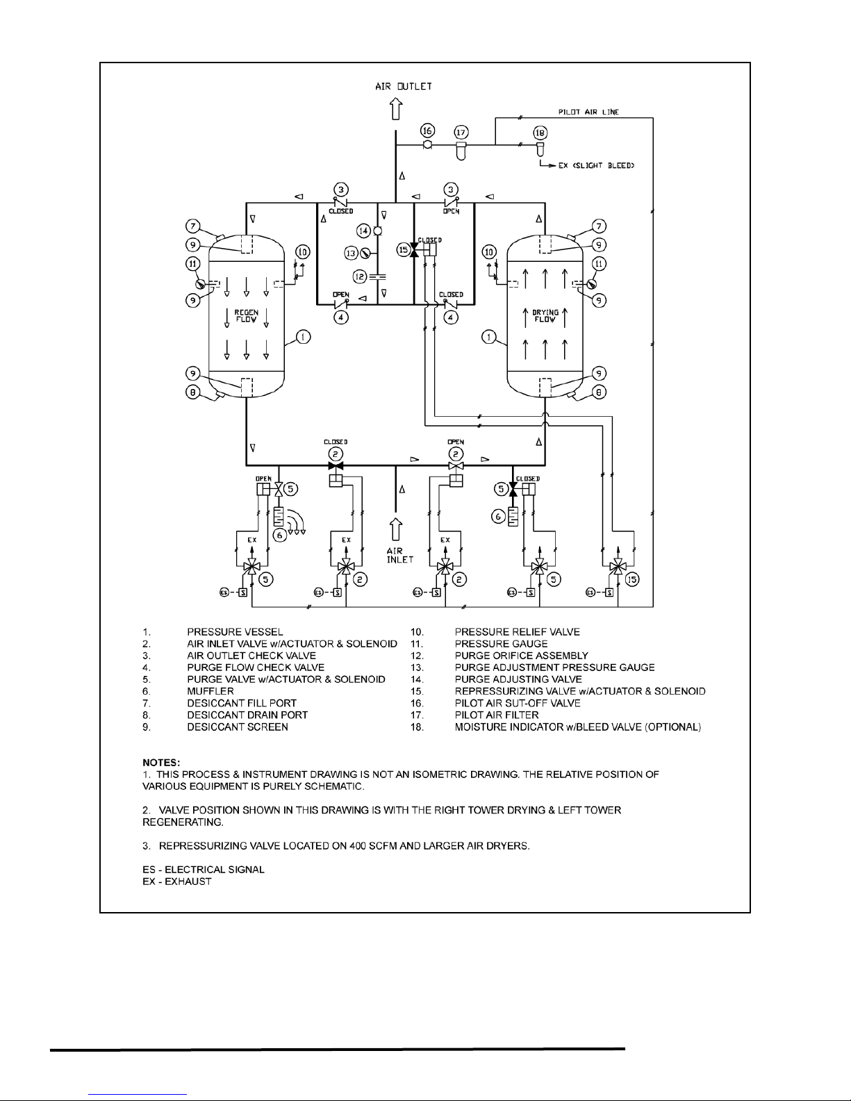
FIGURE 3 — PH/EH SERIES HEATLESS AIR DRYER FLOW DIAGRAM
12
Page 14

PHM MINI SERIES HEATLESS AIR
DRYER INSTALLATION & OPERATION
General
1. If base mounted, secure base plate to hard surface,
or hang securely on a wall.
2. Dryer should be installed indoors or under a shed.
3. Equip dryer with inlet and outlet isolation valves and
a bypass valve for ease of servicing and start-up.
4. Connect electric power to the dryer through a
properly sized fused disconnect switch.
5. Reactivation exhaust may be piped away from the
dryer, making sure proper pipe size is used. For
every ten-foot run, increase the pipe diameter by
one size to reduce back pressure.
6. ELECTRICAL CONNECTIONS: Follow the
recognized local and municipal electrical codes. All
components must be load rated as approved by
NEC, NEMA, CSA and UL.
7. During shipment, wire connections may become
loose. Per UL specification, torque screws inside
enclosure to 20 in-lbs.
8. GROUNDING: It is mandatory that the dryer be
grounded. Use an adequate ground with the
conductor sized to NEC.
9. STORAGE: In case of extended storage period
before the installation, follow these simple
procedures:
a. Seal or cover all the parts
b. Wrap the electrical enclosure
c. Wrap the mufflers
d. If the desiccant is shipped loose, store it inside
10. LEAK TEST: All the dryers are tested at the factory
for any leaks before shipment. An air leak could
develop during transportation or installation.
Pressurize the system and check fo r any leaks.
to avoid any rain or water damage.
Theory of Operation
The PHM Mini Series Heatless Regenerative Air Dryer
features “State of the Art” design. The 4-way inlet valve
and outlet shuttle valve make these dryers trouble-free in
operation and require very little maintenance. Standard
Heatless Regenerative Air Dryers operate on a 10
minute NEMA cycle.
• Drying: 5 minutes
• Regeneration: 4 minutes, 20 seconds (continuous
flow)
• Repressurizing: 40 seconds
While one adsorbent filled tower is drying the inlet flow at
the line pressure, in the upward direction for 5 minutes,
the other tower goes through a mode of desiccant
regeneration in counter flow for 4 minutes, 20 seconds.
Start-Up Procedure
1. Leave the dryer power supply disconnected.
2. Keeping the dryer isolation outlet valve closed,
slowly pressurize both the desiccant chambers to
the line pressure.
3. Check for any leaks in the system.
4. Purge valve should be closed at this time (N.C.
vavle)
5. Connect the dryer power supply
6. The purge valve should open and depressurize one
desiccant chamber.
7. Run the dryer through one or two cycles before
slowly opening the dryer isolation outlet valve.
Operational Observation
1. The drying chamber should be at the line pressure
indicated on the drying chamber pressure gauge.
2. The reactivation chamber should be at 0 PSIG. (Any
higher pressure is an indication of some malfunction;
refer to Troubleshooting Guide on Page 20.)
3. The standard time cycle is 10 minutes. While one
chamber is drying for 5 minutes the other chamber
goes through a mode of desiccant reactivation and
purge for about 4.3 minutes. The purge exhaust
valve then closes to allow the chamber to
repressurize to line pressure before switch-over
occurs at the end of 5 minutes.
13
Page 15

MAINTENANCE
PH/EH SERIES HEATLESS AIR DRYER
MAINTENANCE
WARNING
Disconnect power and depressurize the dryer
completely before starting maintenance procedures.
General
During the first month, clean or replace the pilot air filter
element and repeat periodically. Also, clean the exhaust
mufflers. Replace mufflers if the tower pressure gauge
reads any back pressure during the regeneration cycle.
No lubrication is required for any system.
Daily
Check auto drain on prefilter every shift.
Weekly
1. Check the dryer’s sequence of operation, and valve
operation.
2. Check the purge control setting.
3. Check the operating conditions; inlet pressure, inlet
temperature and the flow rate.
4. Check the moisture indicator. ORANGE color
indicates DRY conditions. If the color is
TRANSLUCENT, refer to the moisture indicator
chart on alarm conditions for probable cause.
(Optional equipment.)
5. Check the purge mufflers for blockage. Possible
indication is back pressure on tower under
regeneration. Replace if necessary.
6. Check the pressure drop across prefilter and
afterfilter. Replace the elements when the differential
reaches 5-10 PSID.
Monthly
Check the pilot air filter element. Replace if necessary.
Three Months
1. Every three (3) months, close the purge adjusting
valve momentarily to check for any leaks in the inlet
and/or check valves indicated by air coming through
the exhaust mufflers.
2. Check the prefilter and afterfilter elements for
excessive clogging or possible damage. Replace as
necessary.
3. Blow down relief valves.
4. Check outlet dewpoint conditions.
Twelve Months
1. Close the inlet and outlet valves on the dryer or
bypass the dryer and completely depressurize the
dryer system. Open the desiccant fill port and check
visually. If desiccant is contaminated with oil or
broken, replace the desiccant.
2. Check for leaking check valves per Table 1
symptoms C & D in Troubleshooting Guide. Repair
or replace as necessary.
3. Remove the inlet switching valves and purge
exhaust valves. Clean and replace worn out seats
and seals.
4. Inspect the pilot air cylinders for leaks or worn out
seals. Repair or replace as necessary.
5. Check repressurizing valve. Repair or replace as
necessary.
6. Check pilot air solenoid valves for possible defects.
Dewpoint Sensor (Optional)
It is recommended to recalibrate the sensor probe
annually to maintain accuracy. Contact your local
distributor or factory for exchange policy.
Calibration: To maintain accuracy, replace the probe
every two years.
Probe Replacement: Turn the normal/demand selector
switch to the normal position. This will disable the
contacts for Dewpoint Demand. Isolate and depressurize
the probe chamber. Remove, and replace the probe.
Pressurize the probe chamber and connect the sensor
cable. A small amount of sample air (approximately 2-10
SCFH) should expel out the chamber needle valve.
Mufflers
Purge mufflers are installed to reduce the noise level.
The mufflers tend to plug up and increase back pressure
over time due to oil carryover and contaminants from
compressor, or due to desiccant dust at the initial startup. To eliminate back pressure, replace muffler after
three months, or when the back pressure increases in
the regenerating tower.
14
Page 16

PHM MINI SERIES HEATLESS AIR
DRYER MAINTENANCE
WARNING
Disconnect power and depressurize the dryer
completely before starting maintenance procedures.
General
Clean the exhaust mufflers. Replace mufflers if there is
any back pressure on the tower in the regeneration
cycle.
No lubrication is required, or should be used on any of
the components.
Daily
1. Check auto drain on prefilter every shift.
2. Follow the start-up procedure.
Weekly
1. Check the shifting, purge and repressurization
operation.
2. Check the operating conditions; inlet pressure, inlet
temperature and the flow rate.
3. Check the moisture indicator. ORANGE color
indicates DRY conditions. If the color is
TRANSLUCENT, refer to the Troubleshooting Guide
on Page 20 for probable cause. (Optional
equipment.)
4. Check the purge mufflers for blockage. Possible
indication is back pressure on tower under
regeneration. Replace if necessary.
5. Check the pressure drop across prefilter and
afterfilter. Replace the elements if the pressure drop
exceeds 7 PSID.
Three Months
1. Check the prefilter and afterfilter elements for
excessive clogging or possible damage. Replace as
necessary.
2. Check outlet dewpoint conditions.
Twelve Months
1. Close the inlet and outlet valves on the dryer or
bypass the dryer and completely depressurize the
dryer system. Open the desiccant fill port and check
visually. If desiccant is contaminated with oil or
broken, replace the desiccant.
2. Inspect and clean the 4-way switching valve, purge
solenoid valve and shuttle valve. Repair or replace
as necessary.
Mufflers
Purge mufflers are installed to reduce the noise level.
The mufflers tend to plug up and increase back pressure
over time due to oil carryover and contaminants from
compressor, or due to desiccant dust at the initial startup. To eliminate back pressure, replace muffler after one
month of operation, and/or when the back pressure
increases to 5 PSIG in the regenerating tower.
Desiccant Replacement Procedure
Activated Alumina Grade A 1/8” diameter is used for all
standard PHM Mini Series Heatless Regenerative Air
Dryers.
Filling Procedures:
1. Make sure the dryer is depressurized.
2. Remove the upper and lower interconnecting pipe
and valves.
3. Remove the desiccant retaining screens on both
ends of the desiccant chambers. Remove all
desiccant.
4. Using a flash light, inspect the inside of each vessel
to be sure they are empty.
5. Install the bottom desiccant screens and make sure
they are secured tightly.
6. Begin filling the towers.
7. Install the top desiccant screens, and all of the
interconnecting pipe and valves.
8. Refer to the star-up procedure listed in the manual.
Desiccant Disposal
Desiccant is not considered a hazardous waste, unless
contaminated with oil or other toxic substances. Disposal
of the desiccant should be handled by a local waste
management company.
15
Page 17
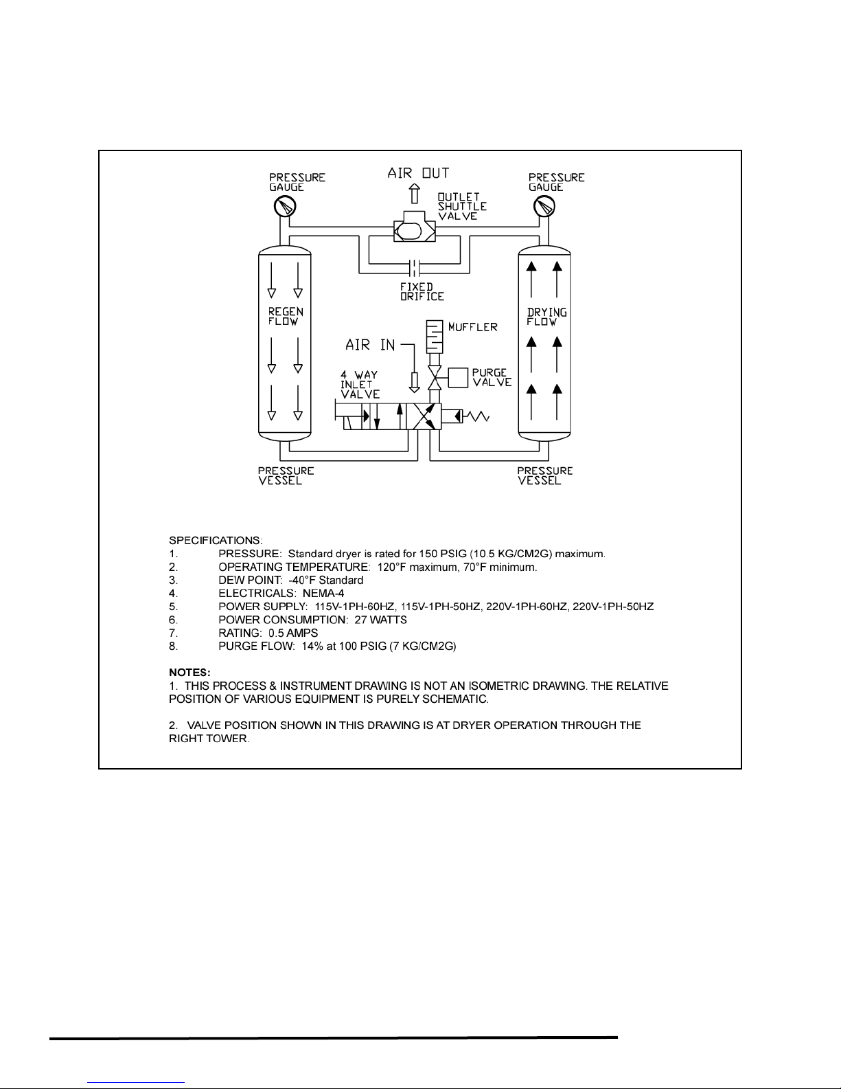
FIGURE 4 — PHM MINI SERIES HEATLESS AIR DRYER FLOW DIAGRAM
16
Page 18

DEWPOINT DISPLAY KEY FUNCTIONS
MEASUREMENT RANGE
FIGURE 5 — DIGITAL DISPLAY
SETPOINT PROGRAMMING
Dryer with dew point demand option:
Alarm set-point values are refereed to as ALr1 and ALr2
in the menu. To access the relevant alarm set-point,
press the SET button once for ALr1 and twice for ALr2.
To adjust the set-point press one of the ARROW
buttons. The display will now flash the current set-point.
Use the ARROW buttons to adjust to the required value.
Press the SET button and the new value will be saved.
Pressing the P button will exit the alarm setting mode
without saving the new value.
Standard setting:
1. ALr1: -20
2. ALr2: -40
Setting for models with low dew point option:
1. ALr1: -70
2. ALr2: -100
o
F (high humidity alarm)
o
F (dew point demand)
o
F (high humidity alarm)
o
F (dew point demand)
1. Max. value: +68
2. min. value: -148
Error Messages.
ErrL = Open circuit, Sensor disconnected.
ErrH = Over Range.
o
o
F
F
17
Page 19
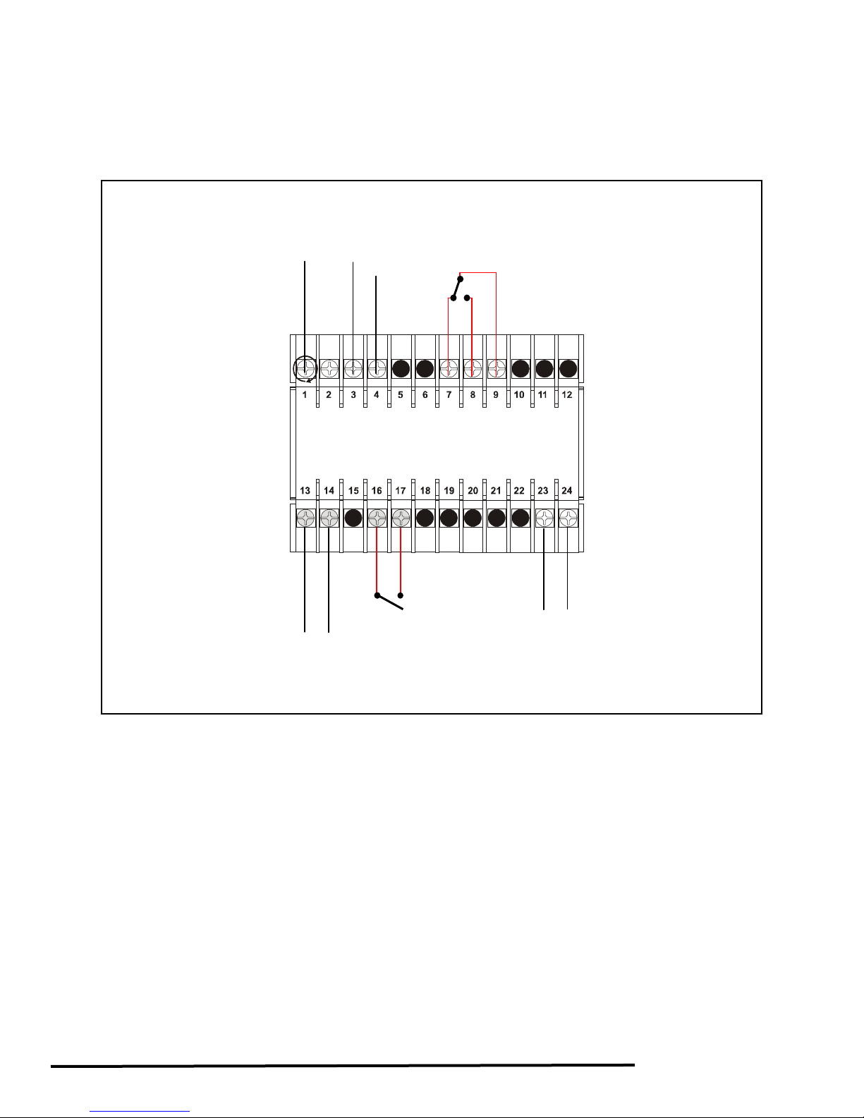
A
A
p
SENSOR
BLUE GREEN
RED
L2
- +
mA Out
ut
L
N L
Power
RE 6 — DEWPOIN
FIGU
T DEMAND (DPD) OPTION WIRING
18
Page 20

OPTIONS LISTING WITH EXPLANATION (PH/EH only)
AUDIBLE ALARM
The Audible Alarm consists of a buzzer with reset push
button and ON/OFF selector switch.
The audible alarm provides an audible warning to alert
an operator that the dryer is not functioning properly.
This option is used with options such as “Failure to Shift
Alarm” or “High Humidity Alarm.”
FAILURE TO SHIFT ALARM
The Failure to Shift Alarm consists of an alarm light that
illuminates if the desiccant towers fail to shift at a
prescribed time. Dry contacts are provided for remote
annunciation.
HIGH HUMIDITY ALARM
The High Humidity Alarm consists of an alarm light
controlled by a hygrometer that senses the dewpoint at
the outlet of the air dryer. This alarm illuminates when
the dewpoint reaches -20°F (-29°C) and above. A small
amount of sample air is required for operation. Dry
contacts are provided for remote annunciation.
Calibration: To maintain accuracy, replace the probe
every two years.
Probe Replacement: Turn the normal/demand selector
switch to the normal position. This will disable the
contacts for Dewpoint Demand. Isolate and depressurize
the probe chamber. Replace the probe. Pressurize the
probe chamber and turn the power back on.
MOISTURE INDICATOR
The moisture indicator consists of a small, clear,
polycarbonate filter filled with a color change silica gel. It
is located at the outlet of the dryer. When the dewpoint is
below -10°F (-23°C), the desiccant is deep orange.
When the dewpoint is above -10°F (-23°C), the
desiccant is translucent. A small amount of sample air is
required for operation.
FILTER HOUSING SILICA GEL
FIGURE 7 — MOISTURE INDICATOR
PANEL LIGHTS
The Panel Light option consists of four lights: Left Tower
Drying, Right Tower Drying, Left Tower Regenerating,
and Right Tower Regenerating. These lights are for
dryer sequence indication.
PLC CONTROLLER
PLC Controller can also be added to control the
operation of standard regenerative dryers. Typically
Square D or Allen Bradley PLCs are used.
DEWPOINT DEMAND CONTROL
“DPD”
The Dewpoint Demand control is an energy saver that
can extend the drying cycle without purging, during
periods of lower moisture loads. The Dewpoint Demand
system offers, in one compact package, the utmost in
flexibility and accuracy sensing the actual dewpoint of
the outlet air. The hygrometer senses the dewpoint at
the outlet of the dryer at the end of the drying cycle, and
extends the drying cycle until the preset adjustable
dewpoint setpoint is reached. During this extended
drying cycle, the purge valves are closed and the
opposite tower is pressurized and prepared for the
drying cycle. The dewpoint demand option reduces
purge loss and extends valve life. This option consists of
the following:
• Digital Dewpoint Display
• Adjustable Setpoints
• Demand Cycle Light
• High Humidity Alarm Light with Dry Contact
• 4-20mA Output
Calibration: To maintain accuracy, the probe should be
recalibrated annually. Recalibrated probes are available
through your local distributor.
Probe Replacement: Isolate and depressurize the
probe chamber. Disconnect the sensor cable from the
sensor. Remove, and replace the probe. Pressurize the
probe chamber and connect the sensor cable. A small
amount of sample air (approximately 2-10 SCFH) should
expel out the chamber needle valve.
19
Page 21

TROUBLESHOOTING
Table 1 — Troubleshooting Guide for PH Series Heatless Regenerative Dryers
Symptoms Cause Remedy
A. Elevated Dewpoint. 1. Low purge flow.
2. Low inlet pressure.
3. Excess moisture carryover.
4. High inlet temperature.
5. Excess air/gas inlet flow.
6. Desiccant coated with oil.
7. Regeneration temperature low.
8. Dewpoint monitor out of calibration.
B. High back pressure on
regenerating tower.
NOTE: The tower should be at ‘0’
PSIG during regeneration cycle. Any
back pressure will result in improper
regeneration.
C. Excessive flow through mufflers. 1. Check valves leaking.
1. Muffler plugged.
2. Check valves leaking.
NOTE: To test for leaking check
valves during regeneration cycle, shut
the purge adjusting valve. If gas is still
passing through, it is an indication of
leaking check valves.
3. Excess purge flow.
4. Restricted purge exhaust piping.
5. Too high purge.
NOTE: To test for leaking, check
valves during regeneration cycle, shut
the purge adjusting valve. If gas is still
passing through, it is an indication of
leaking check valves.
2. Inlet valves did not switch.
3. Purge valve stays open.
4. Repressurizing valve does not
close.
1. Reset purge pressure at the
recommended pressure.
2. Recalculate purge pressure
setting from the chart.
3. Check prefilter element. Check
drains at prefilter and afterfilter.
4. Check aftercooler operation.
5. Check total output of
compressors.
6. Depressurize dryer and inspect
desiccant.
7. *See B.
8. Recalibrate probe.
1. Replace mufflers.
2. Repair or replace faulty check
valves.
3. Check and reset the purge
pressure.
4. Remove obstruction or replace
with larger size pipe.
5. Check purge calibration, plot and
reset.
1. Repair or replace faulty check
valves.
2. See E1 to E4.
3. Check purge solenoid and valve.
Repair or replace faulty purge
valve or solenoid.
4. Check repressurizing solenoid
and valve. Repair or replace faulty
repressurizing valve or solenoid.
20
Page 22

Table 1 — Troubleshooting Guide for PH Series Heatless Regenerative Dryers, continued
Symptoms Cause Remedy
D. No gas flow through the dryer. 1. Both inlet valves closed due to low
inlet pressure.
1. Manually open the inlet valve by
turning the shaft or the ON
actuator.
E. Failure to switch alarm light. 1. Inlet valves did not switch.
2. Faulty timer.
3. Insufficient pilot air pressure.
4. Cylinder leaking or seized up.
F. High pressure drop in dryer. 1. De siccant retainer screens
plugged.
2. Excess flow.
3. High purge flow.
4. Purge valve stays open.
5. Repressurizing valve stays open.
G. Dryer fails to purge. 1. Orifice plate plugged.
2. Purge valve fails to open.
3. Purge valve closed.
4. Purge check valve blocked.
1. Check pilot air solenoid valve.
Repair if necessary.
2. Replace timer.
3. Clean or replace pilot filter
element.
4. Repair or replace pilot air cylinder.
1. Replace desiccant retainer
screens.
2. Check inlet flow conditions.
3. Check and reset purge pressure.
4. Check repressurizing solenoid
valve, repair or replace if
necessary. Check timer.
5. See C4.
1. Clean the orifice plate.
2. See F3.
3. Reset proper purge pressure.
4. Inspect purge check valve.
Replace if necessary.
H. High dewpoint alarm light. See chart on alarm conditions.
I. Moisture indicator color turned
translucent (wet conditions).
1. Bleed valve closed.
2. See probable cause on #1.
1. Open the bleed valve to allow
small amount of air to constantly
flow through the gel.
J. Tower fails to pressurize. 1. Purge valve stays open.
2. Repressurizing valve faulty.
K. Tower does not pressurize fully. 1. Inlet pressure low.
2. Purge pressure too low.
3. Repressurizing period too short.
1. See F3.
2. See C4.
1. Calibrate and plot purge pressure
and reset.
2. Reset proper purge pressure.
3. Check timer sequence of
operation.
L. Excess desiccant dust.
NOTE: If the regenerating tower does
not pressurize fully, desiccant attrition
1. See J & K.
2. Excess flow due to greater demand
in process or addition of extra
compressors.
2. Check outlet flow.
takes place at the time of tower
switchover.
21
Page 23

Table 2 — Troubleshooting Guide for PHM Mini Series Heatless Regenerativ e Dryers
Symptoms Cause Remedy
A. Elevated Dewpoint 1. Low inlet pressure.
2. Excess moisture carryover.
3. Excess gas inlet flow.
4. Desiccant coated with oil.
5. Low inlet air temperature.
1. Increase pressure (minimum 75
PSIG), or reduce flow.
2. Check drains at aftercooler and
prefilter.
3. Check the total output of
compressors.
4. Depressurize the dryer and
replace the desiccant.
5. Raise inlet temperature above
75°F (24°C).
B. High back pressure on
regenerating tower.
NOTE: The tower should be at ‘0’
1. Muffler plugged.
2. Shuttle valve leaking.
1. Replace mufflers.
2. Clean, repair or replace faulty
valve.
PSIG during regeneration cycle.
Any back pressure will result in
improper regeneration.
C. Excessive flow through mufflers. 1. Check valves sticking.
2. Purge valve sticking.
3. Timer short-circuited.
D. Failure to switch. 1. Inlet valves did not switch.
2. Timer short-circuited.
E. High pressure drop in dryer. 1. Desiccant retainer screens
plugged.
2. High purge flow.
3. Purge valve stays open.
F. Dryer fails to purge. 1. Orifice plate plugged.
2. Purge valve stuck closed.
1. Clean, repair or replace valv e.
2. Clean, repair or replace valv e.
3. Replace faulty timer.
1. Clean, repair or replace valv e.
2. Replace faulty timer.
1. Replace desiccant retainer
screens.
2. See. C1 to C3.
3. Clean, repair or replace valv e.
1. Clean the orifice plate.
2. Clean, repair or replace valv e.
22
Page 24

Pneumatech
4909 70
th
Avenue
Kenosha, WI 53144
Phone: 262-658-4300
Fax: 262-658-1945
www.pneumatech.com
 Loading...