

Page 1
Printed in U.S.A. Publication No. OM-A-10E
April 2004
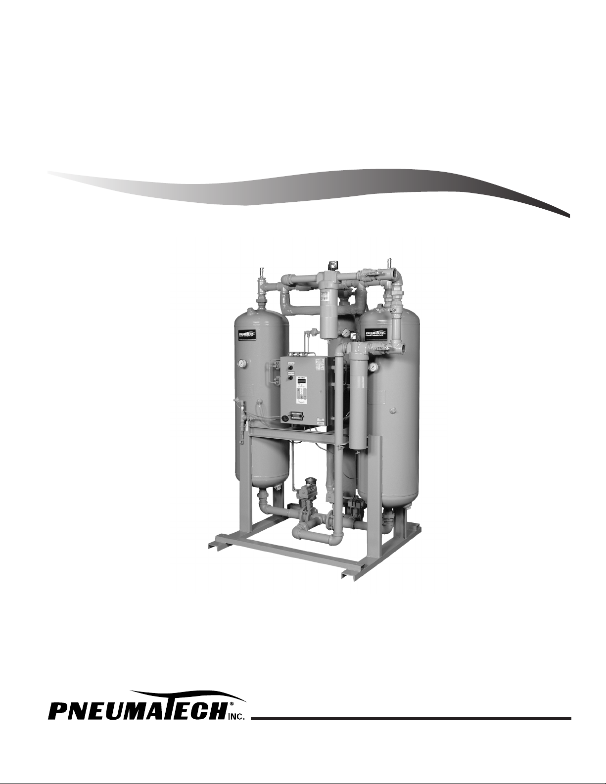
Owner’s Manual
H
EAT
R
EACTIVATED
D
RYERS
PE SERIES/EE SERIES/PB SERIES
Page 2
To receive Extended Warranty, you must register on line at: www.pneumatech.com.
Doing this will extend the warranty to 24
months from date of shipment from Company’s
factory. See back page for actual Warranty
details.
DATE OF PURCHASE
MODEL
SERIAL NO.
Record above information from nameplate.
Retain this information for future reference.
Replacement Price $25.00
Page 3

Pub. No. OM-A-10E — April 2004
1
TABLE OF CONTENTS
Page
General Information . . . . . . . . . . . . . . . . . . . . . . . . . . . . . . . . . . . . . . . . . . . . . . . . . . . . . . 3
Receiving – Inspection . . . . . . . . . . . . . . . . . . . . . . . . . . . . . . . . . . . . . . . . . . . . . . . . . . . 3
Safety Instructions . . . . . . . . . . . . . . . . . . . . . . . . . . . . . . . . . . . . . . . . . . . . . . . . . . . . . . 3
Disclaimer of Warranty . . . . . . . . . . . . . . . . . . . . . . . . . . . . . . . . . . . . . . . . . . . . . . . . . . 4
Desiccant Replacement Procedures. . . . . . . . . . . . . . . . . . . . . . . . . . . . . . . . . . . . . . . . . . . . 5
Filling Procedure. . . . . . . . . . . . . . . . . . . . . . . . . . . . . . . . . . . . . . . . . . . . . . . . . . . . . . . 5
Molecular Sieve Option. . . . . . . . . . . . . . . . . . . . . . . . . . . . . . . . . . . . . . . . . . . . . . . . . . 5
Draining Procedure . . . . . . . . . . . . . . . . . . . . . . . . . . . . . . . . . . . . . . . . . . . . . . . . . . . . . 5
Desiccant Disposal . . . . . . . . . . . . . . . . . . . . . . . . . . . . . . . . . . . . . . . . . . . . . . . . . . . . . 5
Installation & Operation . . . . . . . . . . . . . . . . . . . . . . . . . . . . . . . . . . . . . . . . . . . . . . . . . . . 6
PE & EE Series Heat Reactivated Air Dryer Installation & Operation . . . . . . . . . . . . . . . . . . . 7
General . . . . . . . . . . . . . . . . . . . . . . . . . . . . . . . . . . . . . . . . . . . . . . . . . . . . . . . . . . . 7
Start-Up Procedure. . . . . . . . . . . . . . . . . . . . . . . . . . . . . . . . . . . . . . . . . . . . . . . . . . . . 7
Adjustments & Settings . . . . . . . . . . . . . . . . . . . . . . . . . . . . . . . . . . . . . . . . . . . . . . . . . 8
DMP Microprocessor Control with Cycle Sight ™ . . . . . . . . . . . . . . . . . . . . . . . . . . . . . . 8
Sequence of Operation . . . . . . . . . . . . . . . . . . . . . . . . . . . . . . . . . . . . . . . . . . . . . . . . 10
Shutdown Procedure . . . . . . . . . . . . . . . . . . . . . . . . . . . . . . . . . . . . . . . . . . . . . . . . . . 11
PB Series Heat Reactivated Blower Purge Air Dryer Installation & Operation . . . . . . . . . . . . . 13
General . . . . . . . . . . . . . . . . . . . . . . . . . . . . . . . . . . . . . . . . . . . . . . . . . . . . . . . . . . . 13
Start-Up Procedure. . . . . . . . . . . . . . . . . . . . . . . . . . . . . . . . . . . . . . . . . . . . . . . . . . . . 13
Adjustments & Settings . . . . . . . . . . . . . . . . . . . . . . . . . . . . . . . . . . . . . . . . . . . . . . . . . 14
Sequence of Operation . . . . . . . . . . . . . . . . . . . . . . . . . . . . . . . . . . . . . . . . . . . . . . . . 14
Dry Air Sweep . . . . . . . . . . . . . . . . . . . . . . . . . . . . . . . . . . . . . . . . . . . . . . . . . . . . . . 15
Shutdown Procedure . . . . . . . . . . . . . . . . . . . . . . . . . . . . . . . . . . . . . . . . . . . . . . . . . . 15
Maintenance . . . . . . . . . . . . . . . . . . . . . . . . . . . . . . . . . . . . . . . . . . . . . . . . . . . . . . . . . . .17
PE & EE Series Heat Reactivated Air Dryer Maintenance . . . . . . . . . . . . . . . . . . . . . . . . . . . 17
General . . . . . . . . . . . . . . . . . . . . . . . . . . . . . . . . . . . . . . . . . . . . . . . . . . . . . . . . . . . 17
Daily . . . . . . . . . . . . . . . . . . . . . . . . . . . . . . . . . . . . . . . . . . . . . . . . . . . . . . . . . . . . . 17
Weekly. . . . . . . . . . . . . . . . . . . . . . . . . . . . . . . . . . . . . . . . . . . . . . . . . . . . . . . . . . . . 17
Monthly . . . . . . . . . . . . . . . . . . . . . . . . . . . . . . . . . . . . . . . . . . . . . . . . . . . . . . . . . . . 17
Three Months . . . . . . . . . . . . . . . . . . . . . . . . . . . . . . . . . . . . . . . . . . . . . . . . . . . . . . . 17
Twelve Months . . . . . . . . . . . . . . . . . . . . . . . . . . . . . . . . . . . . . . . . . . . . . . . . . . . . . . 17
Dewpoint Sensor (Optional) . . . . . . . . . . . . . . . . . . . . . . . . . . . . . . . . . . . . . . . . . . . . . 17
Mufflers . . . . . . . . . . . . . . . . . . . . . . . . . . . . . . . . . . . . . . . . . . . . . . . . . . . . . . . . . . . 18
Page 4

2
Pub. No. OM-A-10E — April 2004
PB Series Heat Reactivated Blower Purge Air Dryer Maintenance. . . . . . . . . . . . . . . . . . . . . 18
General. . . . . . . . . . . . . . . . . . . . . . . . . . . . . . . . . . . . . . . . . . . . . . . . . . . . . . . . . . . 18
Daily . . . . . . . . . . . . . . . . . . . . . . . . . . . . . . . . . . . . . . . . . . . . . . . . . . . . . . . . . . . . . 18
Weekly . . . . . . . . . . . . . . . . . . . . . . . . . . . . . . . . . . . . . . . . . . . . . . . . . . . . . . . . . . . 18
Monthly . . . . . . . . . . . . . . . . . . . . . . . . . . . . . . . . . . . . . . . . . . . . . . . . . . . . . . . . . . . 18
Three Months . . . . . . . . . . . . . . . . . . . . . . . . . . . . . . . . . . . . . . . . . . . . . . . . . . . . . . . 18
Twelve Months . . . . . . . . . . . . . . . . . . . . . . . . . . . . . . . . . . . . . . . . . . . . . . . . . . . . . . 18
Dewpoint Sensor (Optional) . . . . . . . . . . . . . . . . . . . . . . . . . . . . . . . . . . . . . . . . . . . . . 18
Mufflers . . . . . . . . . . . . . . . . . . . . . . . . . . . . . . . . . . . . . . . . . . . . . . . . . . . . . . . . . . . 18
Dewpoint Display Key Functions . . . . . . . . . . . . . . . . . . . . . . . . . . . . . . . . . . . . . . . . . . . . . 19
Setpoint Programming . . . . . . . . . . . . . . . . . . . . . . . . . . . . . . . . . . . . . . . . . . . . . . . . . . 19
Open Sensor Condition . . . . . . . . . . . . . . . . . . . . . . . . . . . . . . . . . . . . . . . . . . . . . . . . . 19
Setpoint Limit Indication . . . . . . . . . . . . . . . . . . . . . . . . . . . . . . . . . . . . . . . . . . . . . . . . . 19
Over Range and Under Range Indication . . . . . . . . . . . . . . . . . . . . . . . . . . . . . . . . . . . . . 19
Peak/Valley Indication . . . . . . . . . . . . . . . . . . . . . . . . . . . . . . . . . . . . . . . . . . . . . . . . . . 19
Options Listing with Explanation . . . . . . . . . . . . . . . . . . . . . . . . . . . . . . . . . . . . . . . . . . . . . 21
Audible Alarm . . . . . . . . . . . . . . . . . . . . . . . . . . . . . . . . . . . . . . . . . . . . . . . . . . . . . . . . 21
Failure to Shift Alarm . . . . . . . . . . . . . . . . . . . . . . . . . . . . . . . . . . . . . . . . . . . . . . . . . . . 21
Heater Failure Alarm . . . . . . . . . . . . . . . . . . . . . . . . . . . . . . . . . . . . . . . . . . . . . . . . . . . 21
High Humidity Alarm . . . . . . . . . . . . . . . . . . . . . . . . . . . . . . . . . . . . . . . . . . . . . . . . . . . 21
Moisture Indicator . . . . . . . . . . . . . . . . . . . . . . . . . . . . . . . . . . . . . . . . . . . . . . . . . . . . . 21
Over/Hi Temperature Alarm . . . . . . . . . . . . . . . . . . . . . . . . . . . . . . . . . . . . . . . . . . . . . . 21
Panel Lights . . . . . . . . . . . . . . . . . . . . . . . . . . . . . . . . . . . . . . . . . . . . . . . . . . . . . . . . . . 21
PLC Controller . . . . . . . . . . . . . . . . . . . . . . . . . . . . . . . . . . . . . . . . . . . . . . . . . . . . . . . . 21
Dewpoint Demand Control “DPD” . . . . . . . . . . . . . . . . . . . . . . . . . . . . . . . . . . . . . . . . . . 22
Pulse Purge Regeneration (PPR) with Dewpoint Demand (DPD) . . . . . . . . . . . . . . . . . . . . . . . 22
Troubleshooting. . . . . . . . . . . . . . . . . . . . . . . . . . . . . . . . . . . . . . . . . . . . . . . . . . . . . . . . . 23
Page 5
Pub. No. OM-A-10E — April 2004
3
GENERAL INFORMATION
The Pneumatech Drying System is designed to remove
moisture from compressed air.
When properly installed, the unit requires little
maintenance or adjustment.
A list of service parts is provided on the attached parts list.
This manual contains important safety information. Read
THOROUGHLY and follow the Safety Instructions provided
in this manual and posted on the unit. Keep this manual
near the unit and in a safe place. Replace this manual if it
becomes torn or dirty and cannot be properly used.
Please read the Installation & Operation section of this
manual before attempting to operate the unit.
Please read the Maintenance and Troubleshooting
sections of this manual before beginning any maintenance
or service work on this unit.
RECEIVING – INSPECTION
Inspect equipment. Any concealed shipping
damage must be reported to the carrier
immediately. Damage claims should be filed by
the consignee with the carrier.
All the equipment shipped F.O.B. Kenosha, WI becomes
the property of the purchaser. In all cases of damage,
visible or suspected, contact your local distributor or
Pneumatech before attempting to install equipment.
SERVICE INQUIRIES: Provide Model No., Serial No.,
Operating Pressure, Inlet Temperature, Nature of Problem.
See Dryer Specification Tag located on the control panel.
SAFETY INSTRUCTIONS
When using air compressors and compressed air
accessories, basic safety rules and precautions must
always be followed, including the following:
1. READ ALL INSTRUCTIONS FULLY.
2.
WIRING & BREAKERS
Wiring, breakers and other electrical equipment
must conform to local and national electrical codes.
Do not operate this unit with damaged wiring or
after the unit or air handling parts have been
dropped or damaged in any manner. Notify
authorized service facility for examination, repair
or other adjustments.
3. USE SUITABLE PARTS & ACCESSORIES
Do not use air pressurized accessories or parts in the
air system not suitable for the maximum air pressure
used. Be sure maximum pressure specified by the
accessory manufacturer is well above the working
pressure of your compressor.
4. RELEASE AIR PRESSURE SLOWLY
Fast moving air will stir up dust and debris, which
may be harmful. Release air pressure slowly when
depressurizing your system to avoid bodily injury.
DO NOT install, operate, maintain, adjust
or service this unit without thoroughly
reading this manual.
Comply with the National Electrical Code,
Federal, State and Local Codes when
installing or operating this unit.
Page 6
4
Pub. No. OM-A-10E — April 2004
5.
SECURE DRAIN LINES
Fasten drain lines from prefilter/separator to floor or
drain. Pressurized air will periodically pass through
drain lines, which will cause an unsecured line to
whip and may cause bodily injury.
To provide safe, breathable air, compressor must be
capable of producing at least Grade D breathing air as
described in Compressed Gas Association Commodity
Specification G7.1-1966. Special filtering, purifying and
associated alarm equipment must be used to convert
compressed air to “Breathing Air.” Other special
precautions must also be taken.
Refer to OSHA 29 CFR 1910.134.
DISCLAIMER OF WARRANTY
If this unit is used to produce breathing air, the special
equipment and precautions expressed in OSHA 29 CFR
1910.134 for specifications of the necessary equipment
and special precautions to make Breathing Air MUST BE
used or any warranties are VOID and manufacturer
disclaims any liability whatsoever for loss, personal injury
or damage.
Air from compressor and from Pneumatech Air Drying System, as equipped, is not
safe for human respiration (breathing).
Connect oil coalescing prefilter with automatic drain before the dryer to prevent
any oil or slugs of water carryover into
the desiccant. Connect particulate afterfilter downstream of the dryer to retain any
desiccant dust flowing into the process air
lines.
Page 7

Pub. No. OM-A-10E — April 2004
5
DESICCANT REPLACEMENT PROCEDURES
Pneumatech uses Activated Alumina Grade A desiccant
for all standard heat reactivated air dryers. Dryers up to
1500 SCFM are factory filled with desiccant. Dryers
1800 SCFM and larger are supplied with loose desiccant
in 50 lb. bags. The dryer must be filled with desiccant
before start-up. Dryers ranging from 35 SCFM to 500
SCFM use 1/8" diameter desiccant. Dryers 650 SCFM
and larger use a mix of 1/8” and 1/4" size desiccant.
See the dryer specification sheet or dryer data tag for
amounts per tower.
FILLING PROCEDURE
1. Make sure the dryer is depressurized.
2. Remove the plugs or flanges from the fill ports
located on the top of the pressure vessels.
3. Using a flashlight, inspect the inside of each vessel to
be sure they are empty.
4. Verify that the desiccant drain port located in the
bottom of the pressure vessel is closed tightly.
5. Desiccant is available in 50# bags, or 300# barrels.
Divide the desiccant into equal amounts for each
tower, and verify the correct amount by the
specification tag located on the electrical panel.
Towers can be filled manually with desiccant bags.
A fork lift or overhead crane should be used when
filling with 300# barrels.
6. Dryers 650 SCFM and larger use two sizes of
desiccant. For all heat reactivated models, fill the
tower with the 1/4" diameter Activated Alumina
first , followed by 1/8" Activated Alumina. The
large desiccant (1/4” size) is used to disperse the
inlet air flow.
7. Close the fill ports and put the dryer in service. Refer
to the Start-Up Procedure listed in this manual.
MOLECULAR SIEVE OPTION
(LOW DEWPOINT)
Dryers with optional Molecular Sieve are filled with the
Activated Alumina first and the Molecular Sieve last . The
Molecular Sieve is used as a polishing agent to lower the
dewpoint temperature.
NOTE: The proper amount of desiccant may or may not
fill the vessel to the top.
DRAINING PROCEDURE
The desiccant can be removed by the two methods listed
below. MAKE SURE THE DRYER IS DEPRESSURIZED
PRIOR TO REMOVING THE FILL OR DRAIN PORT.
Method #1 – Remove the drain port and drain the
desiccant into buckets which are then poured into the
proper dumpster or receptacle.
Method #2 – Usually used for large dryers (1000 SCFM
and larger). An industrial dry vacuum cleaner is required
for this method.
1. Remove the desiccant fill port.
2. Using an industrial vacuum cleaner, remove the
desiccant from the vessel.
3. Open the desiccant drain port and remove the
remaining desiccant.
DESICCANT DISPOSAL
Desiccant is not considered a hazardous waste, unless
contaminated with oil or other toxic substances. Disposal
of the desiccant should be handled by a local waste
management company.
Page 8
6
Pub. No. OM-A-10E — April 2004
INSTALLATION & OPERATION
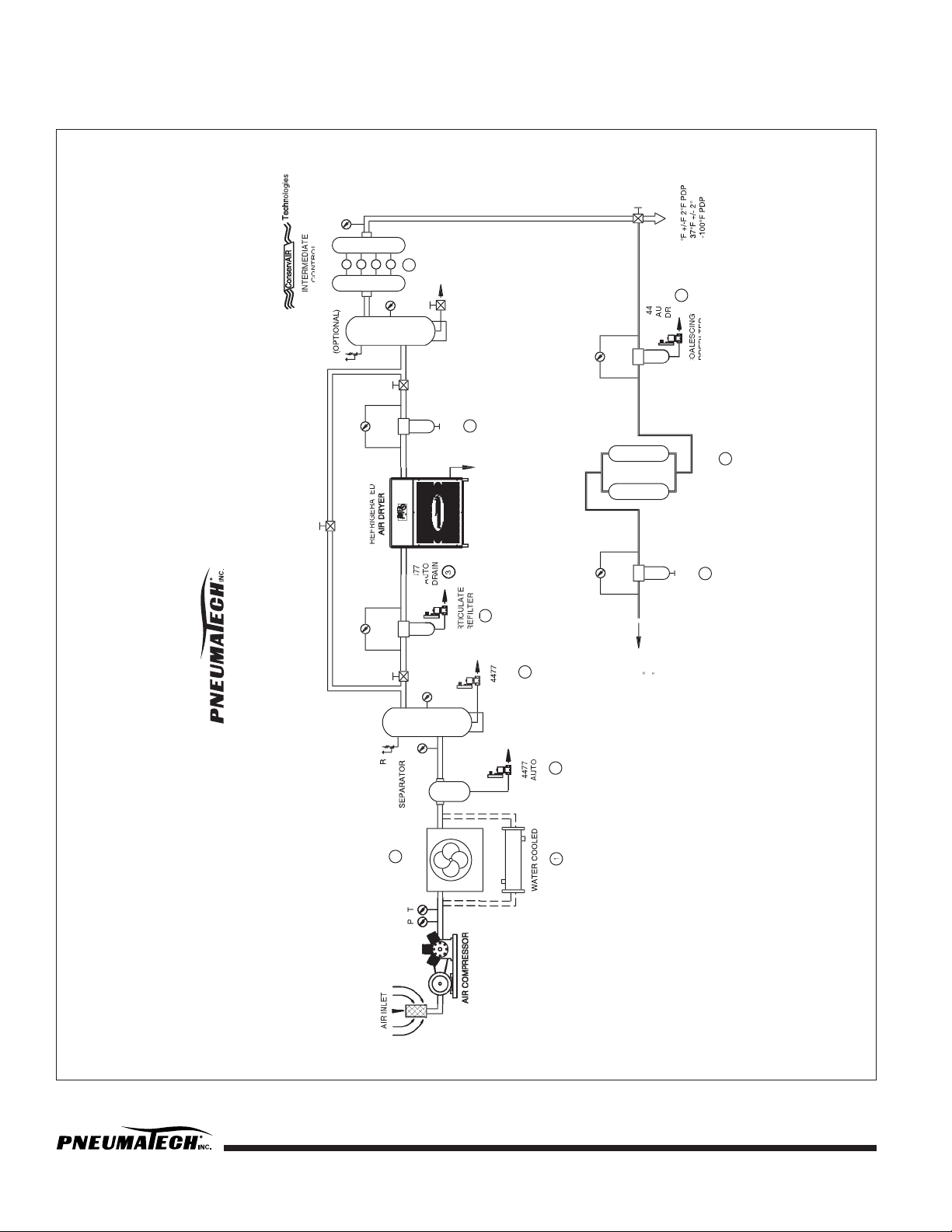
FIGURE 1 — COMPRESSED AIR SYSTEM RECOMMENDED INSTALLATION FLOW DIAGRAM
1. SEE PNEUMATECH BULLETIN PWC-1
2. SEE PNEUMATECH BULLETIN A-3
3. SEE PNEUMATECH BULLETIN A-16
4. SEE PNEUMATECH BULLETIN A-8
5. SEE PNEUMATECH BULLETIN A-10
6. SEE CONSERVAIR BULLETIN CA-200
Page 9

Pub. No. OM-A-10E — April 2004
7
PE & EE SERIES HEAT REACTIVATED AIR
DRYER INSTALLATION & OPERATION
General
1. Install dryer on a level base, indoors or under a shed.
2. During shipment, flange and connecting bolts can
come loose. All bolts should be checked and
tightened as needed.
3. Make sure when the piping is in place that no undue
stress is placed on dryer connections. Union joints or
flexible connections are recommended to relieve
stress. Also, properly support the pipes as needed
with hangers or brackets. Air piping must be
installed by an experienced pipe fitter.
4. Equip dryer with inlet and outlet isolation valves and
a bypass valve for ease of servicing and start-up.
5. Connect electric power to the dryer through a
properly sized fused disconnect switch.
6. Reactivation exhaust may be piped away from the
dryer, making sure proper pipe size is used. The
pipe size should be increased by one size at the
valve, and one additional pipe diameter size for
every ten-foot run to reduce back pressure.
7. ELECTRICAL CONNECTIONS: Follow the
recognized local and municipal electrical codes. All
components must be load rated as approved by
NEC, NEMA, CSA and UL.
8. During shipment, wire connections may become
loose. Per U.L. specification, torque screws inside
enclosure to 20 in-lbs.
9. GROUNDING: It is mandatory that the dryer be
grounded. Use an adequate ground with the
conductor sized to NEC.
10. STORAGE: In case of extended storage period
before the installation, follow these simple
procedures:
a. Seal or cover all the parts
b. Wrap the electrical enclosure
c. Wrap the mufflers
d. If the desiccant is shipped loose, store it inside to
avoid any rain or water damage.
e. Prior to start-up, check the heater element
resistance. The element (phase) to ground should
exceed the resistance value by 20 megohms. If
this value is not indicated, energize the heater at
low voltage to drive the moisture from the
element insulation. Remove the cover to vent the
moisture from the heater terminal enclosure.
11. STEAM CONNECTIONS: For units with optional
steam heat exchanger, the steam connections are
supplied as flanges for both inlet and condensate
return.
12. WATER CONNECTIONS: For units with optional
watercooled aftercooler, connect the water supply
and drain lines.
13. LOW PRESSURE SHUTDOWN FEATURE: The
electrical control on the air dryer system is set up
with low pressure shutdown switch. The controls and
the heater shall stay de-energized as long as the
dryer system is not pressurized above 50 PSIG. This
feature safeguards the system against the loss of air
flow.
14. LEAK TEST: All the dryers are tested at the factory
for any leaks before shipment. An air leak could
develop during transportation or installation.
Pressurize the system and check for any leaks.
Start-Up Procedure
1. Leave the power switch in the OFF position.
2. Keeping the dryer isolation outlet valve closed,
slowly pressurize both the adsorbent chambers to the
line pressure.
3. Check for any leaks in the system.
4. When both adsorbent chambers are at line pressure,
turn the power switch to the ON position.
5. One inlet valve will close, and one purge valve will
open and depressurize one adsorbent chamber. This
may take as long as 10 minutes.
6. Adjust the purge pressure to the recommended setting,
and lock the valve locking mechanism in place.
7. Slowly open the dryer isolation outlet valve to
pressurize the downstream system.
8. To check proper operation of the dryer, use the
manual advance button to cycle the dryer through
the valve sequences. When an event occurs (i.e.
valve opening or closing) wait until complete before
again manually advancing the cycle.
Page 10

8
Pub. No. OM-A-10E — April 2004
Adjustments & Settings
1. Standard Settings
a. Adjust the purge pressure to the recommended
level ____________PSIG.
b. Set heater thermostat TH1. 390°F. (Located in the
bottom of the heater shell)
c. Set over temperature thermostat TH2. 200°F.
(Located in the top of the heater shell)
d. Set desiccant bed thermostat TH3/TH4. 250°F.
e. Set heater failure thermostat TH5. 300°F.
(Located in the bottom of the heater shell)
Optional
f. Set heater failure time delay relay 3 HRS.
Optional
g. Set failure to shift time delay relay TDR 5 HRS.
Optional
h. Check and set the dewpoint monitor Setpoint
Settings. Settings are factory preset. See
dewpoint display settings on Page 19.
i. Open the bleed valve on the optional dewpoint
sensor probe.
j. Dewpoint Demand Setpoint ( ): __________
High Humidity Alarm Setpoint ( ): __________
Pulse Purge Regeneration Setpoint ( ): ______
2. Settings for models with optional Pulse Purge
Regeneration (PPR)
a. Heater control thermostat TH1. 390°F (Located in
the bottom of the heater shell.)
b. Over temperature thermostat TH2. 500°F
(Located in the top of the heater shell.)
c. Dessiccant bed thermostat TH3/TH4. 250°F
d. Heater failure thermostat TH5. 300°F (Located in
the bottom of the heater shell.) Optional
e. Failure to shift time delay relays (TDR). 5 hours
Optional
DMP Microprocessor Control with Cycle Sight ™
Available on most standard units
INTRODUCTION
1.
GENERAL: The Pneumatech DMP controller is a
microprocessor controlled, ten (10) channel
sequence timer with LCD and LED display features.
The DMP controller consists of the main control unit
and the remote LCD, LED and I/O module. The two
units are connected via ribbon cable.
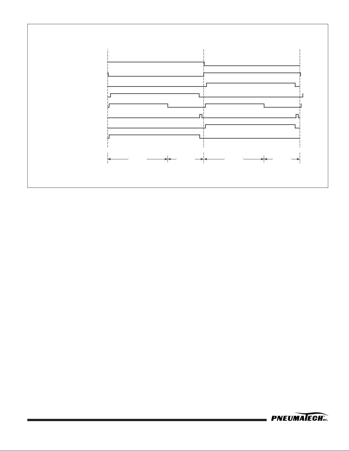
2. SEQUENCE OF OPERATION: The sequence of
operation is based on an 8 hour NEMA Cycle, with
one-half of the total time being for adsorption of
moisture from the process gas and one-half for
desiccant regeneration. Specifics of the timing
sequence are detailed in Figure 2, the Sequence of
Operation Diagram (SDG-1), on Page 11. If power
is interrupted, the DMP controller electronically stores
the point in the timing cycle at which power was
removed. When power is reapplied, timing will
resume from that point in the cycle. At all times
during operation, the current status of the timing
cycle is indicated graphically by the LEDs and
textually on the LCD screen.
3. FEATURES
• CD screen indicating right/left tower heating/
cooling, right/left tower temperature, actual
sequence time, low pressure alert, demand cycle
indication (opt.), fail to shift alert (opt.).
• LED sequence annunciator indicating R/L tower
drying/regenerating, heater on, low pressure
alarm, demand cycle indicator (opt.), high
humidity alarm (opt.), fail to shift alarm (opt.).
• Timer and setting memory
• Time cycle advance button
• Open thermocouple protection
MODE OF OPERATION
1.
START UP: The Digital Microprocessor Sequence
Controller will start to operate as soon as the power
is supplied and the unit is turned on. The load
outputs will recycle on and off based on an 8 hour
NEMA Cycle. The sequence will proceed according
to the Sequence of Operation Diagram SDG-1. See
Figure 2. The point at which the timing starts
depends on where the cycle stopped when power
was last turned off.
2. MANUAL CYCLE ADVANCE: The backside of the
remote I/O module contains an “ADVANCE” push
button. Each time the “ADVANCE” push button is
pressed, the timing cycle advances by 1 minute. If
the “ADVANCE” push button is held continuously for
5 seconds, the current time will advance by 30
minutes for every additional second it is held. The
“ADVANCE” push button is disabled whenever the
timing is stopped by an inhibit switch.
Page 11
Pub. No. OM-A-10E — April 2004
9
3. LOW PRESSURE: All heated regenerative dryers
are supplied with Low Pressure Switch Inhibit. When
the low pressure is detected, all timing functions stop
and all loads are de-energized. The red LED on the
remote I/O module will light up and “LOW
PRESSURE” will be displayed on the LCD screen.
This function will put dryer operation in the fail-safe
mode. Both the inlet valves will fail OPEN and the
purge valves will fail CLOSED. As soon as the
pressure is restored, the normal functions will
resume. The Low Pressure inhibit is set to operate
when the pressure in the dryer drops to 50 PSIG
(3.4 BarG).
4. RELAY OUTPUTS (DRY CONTACTS): There are
two relay outputs for remote annunciation. The
output is normally open rated for 10 AMPS resistive
at 125VAC, 5 AMPS resistive at 30VDC. The outputs
are for the inhibit Failure to Switch and High
Humidity. If one or both inhibits are made, the relays
will be energized and the LED on the remote I/O will
light up.
HEATER TEMPERATURE CONTROL
1.
THERMOCOUPLE INPUTS (3):
T.C.1 – Heater temperature.
T.C.2 – Left Tower desiccant bed temperature.
T.C.3 – Right Tower desiccant bed temperature.
2. TEMPERATURE DISPLAY: The temperature
measured at each thermocouple can be displayed,
one at a time, on the LCD screen of the remote I/O
module. Pressing the “TEMP DISPLAY” button on the
remote I/O module will display the temperature.
Each press of the “TEMP DISPLAY” button will
advance the thermocouple temperature displayed to
the next thermocouple in the above order. Pressing
the button a fourth time will display the current cycle
in minutes.
3. TEMPERATURE UNITS: The temperature measured
can be indicated in °C or °F. The unit can be
selected by changing the “UNITS” slide switch on
the back side of the remote I/O module.
4. TEMPERATURE SETPOINTS: For each location at
which a temperature is measured, there is a high
temperature setpoint. If the temperature for a given
area rises above its setpoint, the heater (LOAD 5)
will be disabled. The heater will be re-energized
when the temperature drops to the setpoint less the
specified hysteresis.
a. To set the high temperature setpoints move the
slide switch on the back of the module to the
“TEMP SET” position.
b. The high temperature set point to be adjusted will
be displayed on the LCD. Use the “TEMP
DISPLAY” button to choose which of the three
high temperature setpoints to change.
c. The high temperature setting will be displayed on
the LCD. Use the “UP” and “DOWN” push
buttons on the back of the remote I/O module to
set the temperature in 1°C increments.
d. The new high temperature setpoint will not take
effect until the selector switch is returned to
“RUN” mode.
5. OPEN THERMOCOUPLE PROTECTION: If an
open (disconnected or disabled) thermocouple is
detected, the heater will be disabled and a blinking
error message will appear on the LCD indicating
which thermocouple is open.
OPTIONAL CONTROLS AND ALARMS
1.
DEWPOINT DEMAND SEQUENCE CONTROL:
The dewpoint demand mode function will be
operational if there are 5 minutes before the end of
the drying cycle, and the dewpoint is below the
preset level. When in the dewpoint demand mode,
all of the timing functions stop. The yellow LED on the
remote I/O module will light up and “DEMAND
CYCLE” will be indicated on the LCD. When the
dewpoint reaches the preset dewpoint level, the
towers will switch and the normal mode cycle will
commence. The dewpoint demand mode function
will be disabled if the dewpoint is above the preset
level.
2. HIGH HUMIDITY: The high humidity alarm
function is indicated by a red LED on the remote I/O
module. The high humidity relay will energize for
remote annunciation. All the normal functions will be
maintained.
This unit may be damaged by electrostatic
discharge. Follow procedures for static
sensitive parts when handling, shipping or
installing this unit.
Page 12

10
Pub. No. OM-A-10E — April 2004
3.
FAIL TO SHIFT: The fail to shift inhibit will be
energized if the inhibit switch remains closed for 30
minutes beyond the normal cycle. Fail to shift will be
indicated by the red LED on the remote I/O module
and the fail to shift relay will be energized for remote
annunciation. The fail to shift inhibit is an indication
of a malfunction of the tower switching valves or
purge exhaust valves.
4. PULSE PURGE REGENERATION (PPR) WITH
DEWPOINT DEMAND: PE and EE series dryers
with optional Pulse Purge Regeneration (PPR) are
controlled by a Programmable Logic Controller (PLC)
instead of the standard DMP controller with Cycle
Sight™. PPR utilizes an 8 hour drying/regeneration
cycle but changes the purge cycle from continuous
purge to a 30-minute purge period. After the purge
period, the tower is pressurized with hot dry air for a
30-minute hold period. After the 30-minute hold
period, the dryer depressurizes and repeats the 30minute purge period. This cycle (PPR) repeats three
times followed by a 30-minute cooling period which
cools the desiccant bed to line temperature before the
towers switch. The PPR mode reduces the purge cycle
by 50% and significantly reduces heater run time. All
PPR functions are controlled by the PLC. If for any
reason the system should experience a deteriorating
dewpoint, the PLC will default to the standard cycle
until full performance recovery has been achieved.
When the system senses full recovery, it will
automatically switch to PPR mode. The default mode
ensures performance integrity. PPR is packaged with
Dewpoint Demand and High Humidity alarm for
maximum energy savings. The following hour meters
are provided to indicate savings: Heater Run Time,
Dryer Run Time, Demand Time.
Sequence of Operation
The sequence of operation of the External Heat
Reactivated Dryer can be readily followed by referring to
the following flow schematic and timing sequence.
During initial start-up with the power switch in the OFF
position, and the towers pressurized with air, both inlet
valves stay in the OPEN position (standard with models
PE-300 and larger) and the purge valves stay in the
CLOSED position. This type of fail safe valve operation
allows the air to dry through both the towers, without any
purge in the event of loss of power to dryer. This will give
you extended drying time until desiccant chambers are
saturated.
The desiccant is designed to handle air saturated with
water vapor only. Any liquids or slugs of water tend to
decrease the efficiency of the desiccant and retard the
regeneration process to provide the designed dewpoint.
With the power switch in the ON position at
time equal to 0.0 hrs., the left tower air inlet valve is
open to allow the air to pass through the left tower. The
right tower inlet valve is closed. The saturated compressed
air/gas passes through the desiccant in the left tower
where the desiccant adsorbs the moisture, and the dry air
at a pressure dewpoint of -40°F or less exits through the
left outlet check valve and goes out into the plant air
system through the afterfilter.
At time equal to 5 minutes, the right lower purge
valve depressurizes the right tower so that the desiccant is
not disturbed (on high pressure dryers depressurization is
accomplished by a designated valve). At the same time
the heater is energized to commence the heating cycle.
NOTE: As soon as the purge valve has opened, adjust the
purge adjustment valve to the recommended purge control
setting. This adjustment should only be required once, and
then the locking mechanism should be locked in place.
The temperature of the purge air is controlled by the
heater control thermostats to maintain the preset
temperature. The hot and dry purge air passes through the
right purge flow check valve and enters the desiccant bed
at the top of the tower and removes the previously
adsorbed water vapor from the desiccant and purges out
through the right purge valve, and is exhausted into the
atmosphere through the exhaust muffler.
NOTE: During the regeneration air flow through the
desiccant bed, the tower pressure gauge should read 0
PSIG. Any higher pressure is an indication of a plugged
muffler, which will retard the regeneration of desiccant.
During the heating cycle, the bed temperature should rise
to 250°F (121°C) in approximately two hours. The heater
control thermostats will cycle the heater to maintain this
250°F bed temperature.
At time equal to 2 hr. 30 minutes, the heater is deenergized, and the cooling cycle begins to reduce the
temperature in the desiccant bed and prepare it for the
drying cycle.
At time equal to 3 hr. 50 minutes, the right tower
purge valve will close. With this valve closed, the flow of
purge air repressurizes the right tower and prepares it for
switch-over.
At time equal to 4 hr., the right tower inlet valve
opens, and the left tower inlet valve closes, so the flow of
wet air/gas is switched from left chamber to the right
chamber.
At time equal to 4 hr. 5 minutes, the left tower
purge valve opens and depressurizes the left tower. The
above sequence is then repeated on the opposite towers.
Page 13
Pub. No. OM-A-10E — April 2004 11
FIGURE 2 — SDG-1: SEQUENCE OF OPERATION DIAGRAM
Shutdown Procedure
Externally Heated dryers are typically installed in 24 Hr.
operations. The dryers operate on a standard time cycle
of 8 hours, 4 hours drying and 4 hours regenerating. This
cycle should not be interrupted (except for servicing). If the
dryer needs to be shut down for a certain shift or
weekend; the dryer should be turned off at the end of the
4 hour regenerating cycle, and with both towers at line
pressure. If servicing is required advance the time
sequence so the purge valves close, and pressurize both
towers. At this time, the dryer can be turned off.
1. If the compressed air system has been
piped with a bypass around the dryer, then
the following should be completed:
a. Open the bypass valve to allow process flow to
continue downstream, then close the dryer outlet
isolation valve.
b. Turn the dryer ON/OFF switch to the OFF
position.
c. Close the dryer inlet isolation valve on the dryer
bypass piping. At this time the dryer is isolated
and can be depressurized for servicing.
2. If the compressed air system has not been
piped with a bypass, then the following
should be completed:
a. Turn the power switch to the OFF position.
b. The tower switching valves are normally open
valves; therefore, with the power off the inlet
valves to the towers will be open, and the purge
valves will close. This will give you extended
drying time until desiccant chambers are
saturated.
1
LEFT TOWER
SWITCHING
ON
OFF
ZERO
ZERO
240 MINUTES
240 MINUTES
480 MINUTES
480 MINUTES
ZERO
R TOWER
HEATING
R TOWER
COOLING
240 MINUTES
150 390
480 MINUTES
2
RIGHT TOWER
SWITCHING
ON
OFF
3
LEFT TOWER
REGENERATING
ON
OFF
4
RIGHT TOWER
REGENERATING
ON
OFF
5
DEMAND
CYCLE
ON
OFF
N/A
HEATER
TIMING STAGE:
ON
OFF
6
LEFT TOWER
DEPRESSURIZING (OPT.)
ON
OFF
7
RIGHT TOWER
DEPRESSURIZING (OPT.)
ON
OFF
L TOWER
HEATING
L TOWER
COOLING
Page 14
12 Pub. No. OM-A-10E — April 2004
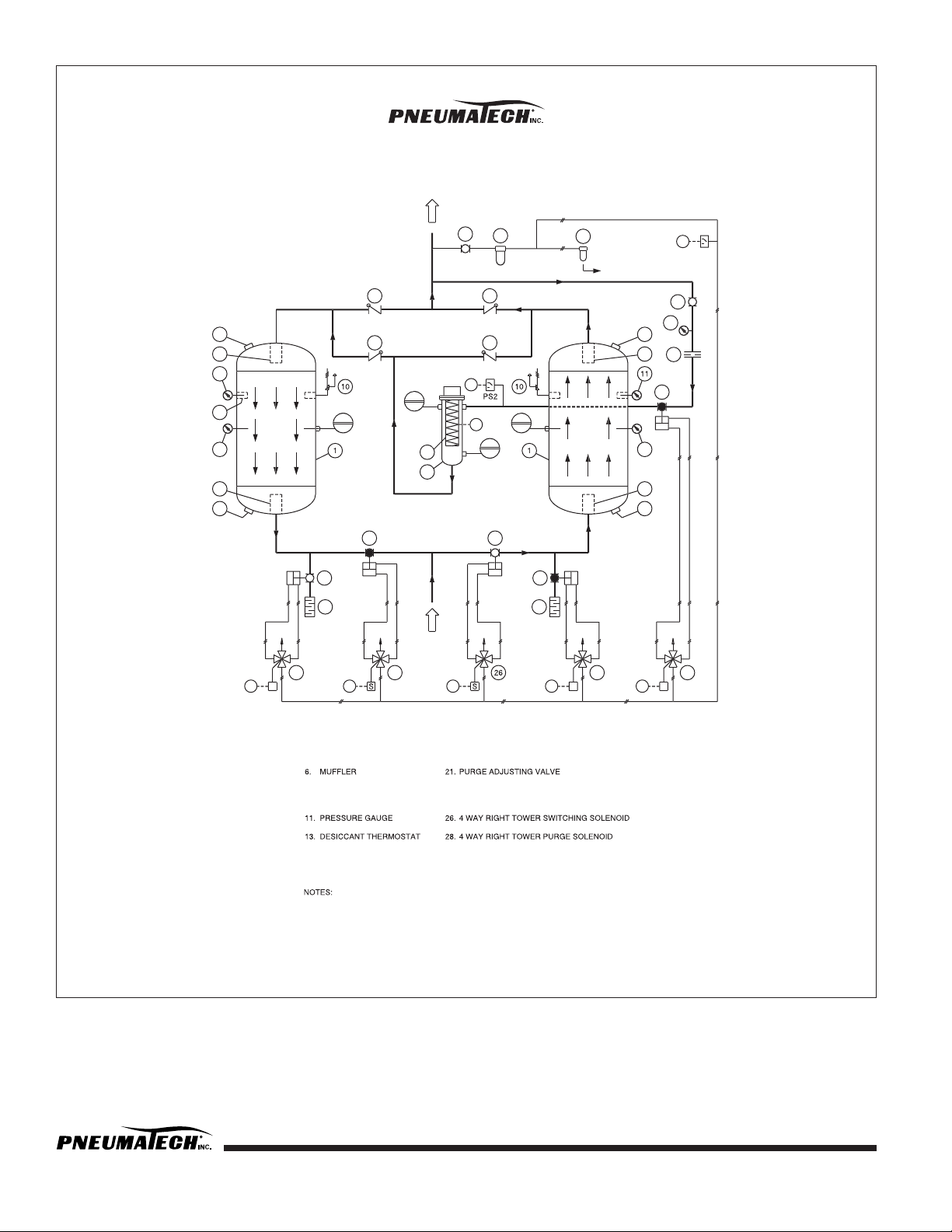
FIGURE 3 — PE & EE SERIES FLOW DIAGRAM
S
6
5
25
28
S
6
5
OPEN
CLOSED
OPEN
CLOSED
3
OPEN
3
AIR OUTLET
CLOSED
13
9
8
9
EX (SLIGHT BLEED)
CLOSED
18
S
29
16
CLOSED
OPEN
23
20
19
PS1
15139
8
9
PILOT AIR LINE
9
ES
ES
ES
ES
ESESES
ES
TYPICAL PE SERIES
FLOW DIAGRAM
PRESSURE VESSEL
3.
AIR OUTLET CHECK VALVE
PURGE FLOW CHECK VALVE
5.
PURGE VALVE
DESICCANT FILL PORT
8.
DESICCANT DRAIN PORT
9.
DESICCANT SCREEN
10.
PRESSURE RELIEF VALVE
TEMPERATURE GAUGE
ELECTRIC HEATER
15.
HEATER CHAMBER
16.
HEATER CONTROL THERMOSTAT
OVER TEMPERATURE THERMOSTAT
18.
PURGE ISOLATION VALVE (OPTIONAL)
19.
PURGE ORIFICE ASSEMBLY
20.
PURGE ADJUSTMENT PRESSURE GAUGE
PILOT AIR SHUT-OFF VALVE
23.
PILOT AIR FILTER
MOISTURE INDICATOR (OPTIONAL)
25.
4 WAY LEFT TOWER SWITCHING SOLENOID
4 WAY LEFT TOWER PURGE SOLENOID
29.
4 WAY PURGE ISOLATION
SOLENOID (OPTIONAL)
THIS PROCESS & INSTRUMENT DRAWING IS NOT AN ISOMETRIC DRAWING,
THE RELATIVE POSITION OF VARIOUS EQUIPMENT IS PURELY SCHEMATIC.
VALVE POSITION SHOWN IN THIS DRAWING IS AT DRYER OPERATION
THROUGH THE RIGHT TOWER.
EXHAUST
ES -
ELECTRICAL SIGNAL
PS1 -
LOW PRESSURE SWITCH
PS2 -
PURGE ISOLATION PRESSURE SWITCH (OPTIONAL)
FLOW
REGEN
FLOW
DRYING
Page 15

Pub. No. OM-A-10E — April 2004 13
PB SERIES HEAT REACTIVATED BLOWER
PURGE AIR DRYER INSTALLATION &
OPERATION
General
1. Install dryer on a level base, indoors or under a
shed.
2. During shipment flange and connecting bolts can
come loose. All bolts should be checked and
tightened as needed.
3. Make sure when the piping is in place that no undue
stress is placed on dryer connections. Union joints or
flexible connections are recommended to relieve
stress. Also, properly support the pipes as needed
with hangers or brackets. Air piping must be
installed by an experienced pipe fitter.
4. Equip dryer with inlet and outlet isolation valves and
a bypass valve for ease of servicing and start-up.
5. Connect electric power to the dryer through a
properly sized fused disconnect switch.
6. Reactivation exhaust may be piped away from the
dryer, making sure proper pipe size is used. Pipe
size should be increased by one size at the valve,
and one additional pipe diameter size for every tenfoot run to reduce back pressure.
7. ELECTRICAL CONNECTIONS: Follow the
recognized local and municipal electrical codes. All
components must be load rated as approved by
NEC, NEMA, CSA and UL.
8. During shipment, wire connections may become
loose. Per U.L. specification, torque screws inside
enclosure to 20 in-lbs.
9. GROUNDING: It is mandatory that the dryer be
grounded. Use an adequate ground with the
conductor sized to NEC.
10. STORAGE: In case of extended storage period
before the installation, follow these simple
procedures:
a. Seal or cover all the parts
b. Wrap the electrical enclosure
c. Wrap the mufflers
d. If the desiccant is shipped loose, store it inside to
avoid any rain or water damage.
e. Prior to start-up, check the heater element
resistance. Element (phase) to ground should
exceed the resistance value by 20 megohms. If
this value is not indicated, energize the heater at
low voltage to drive the moisture from the
element insulation. Remove the cover to vent the
moisture from the heater terminal enclosure.
11. STEAM CONNECTIONS: For units with optional
steam heat exchanger, the steam connections are
supplied as flanges for both inlet and condensate
return.
12. WATER CONNECTIONS: For units with optional
watercooled aftercooler, connect the water supply
and drain lines.
13. BLOWER MOUNTING BOLTS: Loosen the blower
mounting bolts to serve as riding pins only.
14. BLOWER ROTATION: When making electrical
connections, check the rotation of blower for proper
operation. Momentarily energize the blower to
check for the rotation. In case of reverse rotation,
disconnect the power and change two leads on the
blower starter to change the direction of rotation.
15. LEAK TEST: All the dryers are tested at the factory
for any leaks before shipment. An air leak could
develop during transportation or installation.
Pressurize the system and check for any leaks.
Start-Up Procedure
1. Leave the power switch in the OFF position.
2. Keeping the dryer outlet isolation valve closed,
slowly pressurize both the adsorbent chambers to the
line pressure.
3. Check for any leaks in the system.
4. Open blower outlet/throttling valve.
5. Engage the blower starter to test the rotation
according to the direction-of-rotation arrow which is
affixed to the blower casing. (If incorrect switch any
two leads to reverse the rotation.)
6. When the towers are at line pressure, turn the power
switch to the ON position.
7. One inlet valve will close, and the chamber purge
valve will open and depressurize. This may take as
long as 10 minutes.
8. When the blower motor turns off and the dry air
sweep begins, adjust the cooling flow pressure to the
recommended setting, and lock the valve locking
mechanism in place.
Page 16

14 Pub. No. OM-A-10E — April 2004
9. Slowly open the dryer outlet isolation valve to
pressurize the downstream system.
10. Use the manual advance button to cycle the dryer
through the valve sequences.
Adjustments & Settings
1. At start-up note the blower pressure. The intake filter
should be changed when there is a significant drop
in blower pressure.
2. Adjust the cooling flow pressure at the recommended
level ______ PSIG.
3. Set heater thermostat TH1. 390°F (Located in the
bottom of the heater shell)
4. Set over temperature thermostat TH2. 200°F.
(Located in the top of the heater shell)
5. Set desiccant bed thermostat TH3/TH4. 250°F.
6. Set heater failure thermostat TH5. 300°F. (Located in
the bottom of the heater shell) Optional
7. Set heater failure time delay relay 3 HRS. Optional
8. Set failure to shift time delay relay 5 HRS. Optional
9. Check and set the dewpoint monitor Setpoint
Settings. Settings are factory preset. See dewpoint
display setting on Page 19.
10. Open the bleed valve on the optional dewpoint
sensor probe.
11. Dewpoint Demand Setpoint (SP1): ______
12. High Humidity Alarm Setpoint (SP2): ______
Sequence of Operation
The sequence of operation of the External Heat
Reactivated Blower Purge Dryer can be readily followed
by referring to the following flow schematic and timing
sequence.
During initial start-up with the power switch in the OFF
position, and the towers pressurized with air, both inlet
valves stay in the OPEN position and the purge valves stay
in the CLOSED position. This type of fail safe valve
operation allows the air to dry through both the towers,
without any purge in the event of loss of power to dryer.
This will give you extended drying time until desiccant
chambers are saturated.
The desiccant is designed to handle air saturated with
water vapor only. Any liquids or slugs of water tend to
decrease the efficiency of the desiccant and retard the
regeneration process to provide the designed dewpoint.
With the power switch in the ON position at
time equal to 0.0 hrs., the left tower air inlet valve is
open to allow the air to pass through the left tower. The
right tower inlet valve is closed. The saturated compressed
air/gas passes through the desiccant in the left tower
where the desiccant adsorbs the moisture, and the dry air
at a pressure dewpoint of -40°F or less exits through the
left outlet check valve and goes out into the plant air
system through the afterfilter.
At time equal to 5 minutes, the right tower purge
valve depressurizes the right tower so that the desiccant is
not disturbed.
At time equal to 10 minutes, the blower and heater
are energized to commence the regeneration cycle.
The temperature of the purge air is controlled by the
heater control thermostats to maintain the preset
temperature. During the heating cycle, the bed
temperature should rise to 250°F (121°C) in
approximately two hours. The heater control thermostats
will cycle the heater to maintain this 250°F bed
temperature. The hot purge air passes through the right
purge flow check valve and enters the desiccant bed at the
top of the tower. The hot purge air removes the previously
adsorbed water vapor from the desiccant and purges out
through the right purge valve, and is exhausted into the
atmosphere through the exhaust muffler.
NOTE: During the regeneration air flow through the
desiccant bed, the tower pressure gauge should read 0
PSIG. Any higher pressure is an indication of a plugged
muffler, which will retard the regeneration of desiccant. In
the event of a leaking valve or check valve a back
pressure will develop. A significant back pressure will
cause the blower amps to increase and kick off the blower
on high overloads.
At time equal to 3 hrs., the blower and heater are deenergized, and the cooling flow valve opens to start the
cooling cycle to reduce the temperature in the desiccant
bed and prepare it for the drying cycle.
NOTE: As soon as the cooling cycle begins, adjust the
purge adjustment valve to the recommended purge control
setting. This adjustment should only be required once, and
then the locking mechanism should be locked in place.
Page 17

Pub. No. OM-A-10E — April 2004 15
Dry Air Sweep
In order to maintain constant dewpoint, the Pneumatech
dryer uses a dry air sweep during the cool down cycle.
At time equal to 3 hr. 50 minutes, the purge valve
will close, and the flow or purge air repressurizes the right
tower and prepares it for switch-over.
At time equal to 4 hr., the right tower inlet valve
opens, and the left tower inlet valve closes, so the flow of
wet air/gas is switched from left chamber to the right
chamber. The above sequence is then repeated on the
opposite towers.
Shutdown Procedure
Externally Heated dryers are typically installed in 24 Hr.
operations. The dryers operate on a standard time cycle
of 8 hours, 4 hours drying and 4 hours regenerating. This
cycle should not be interrupted (except for servicing). If the
dryer needs to be shut down for a certain shift or
weekend; the dryer should be turned off at the end of the
4 hour regenerating cycle, and with both towers at line
pressure. If servicing is required advance the time
sequence so the purge valves close and both towers
pressurize. At this time, the dryer can be turned off.
1. If the compressed air system has been
piped with a bypass around the dryer, then
the following should be completed:
a. Open the bypass valve to allow process flow to
continue downstream, then close the dryer outlet
isolation valve.
b. Turn the dryer ON/OFF switch to the OFF
position.
c. Close the dryer inlet isolation valve on the dryer
bypass piping. At this time the dryer is isolated
and can be depressurized for servicing.
2. If the compressed air system has not been
piped with a bypass, then the following
should be completed:
a. Turn the power switch to the OFF position.
b. The tower switching valves are normally open
valves; therefore, with the power off, the inlet
valves to the towers will be open, and the purge
valves will close. This will give you extended
drying time until desiccant chambers are
saturated.
Page 18
16 Pub. No. OM-A-10E — April 2004
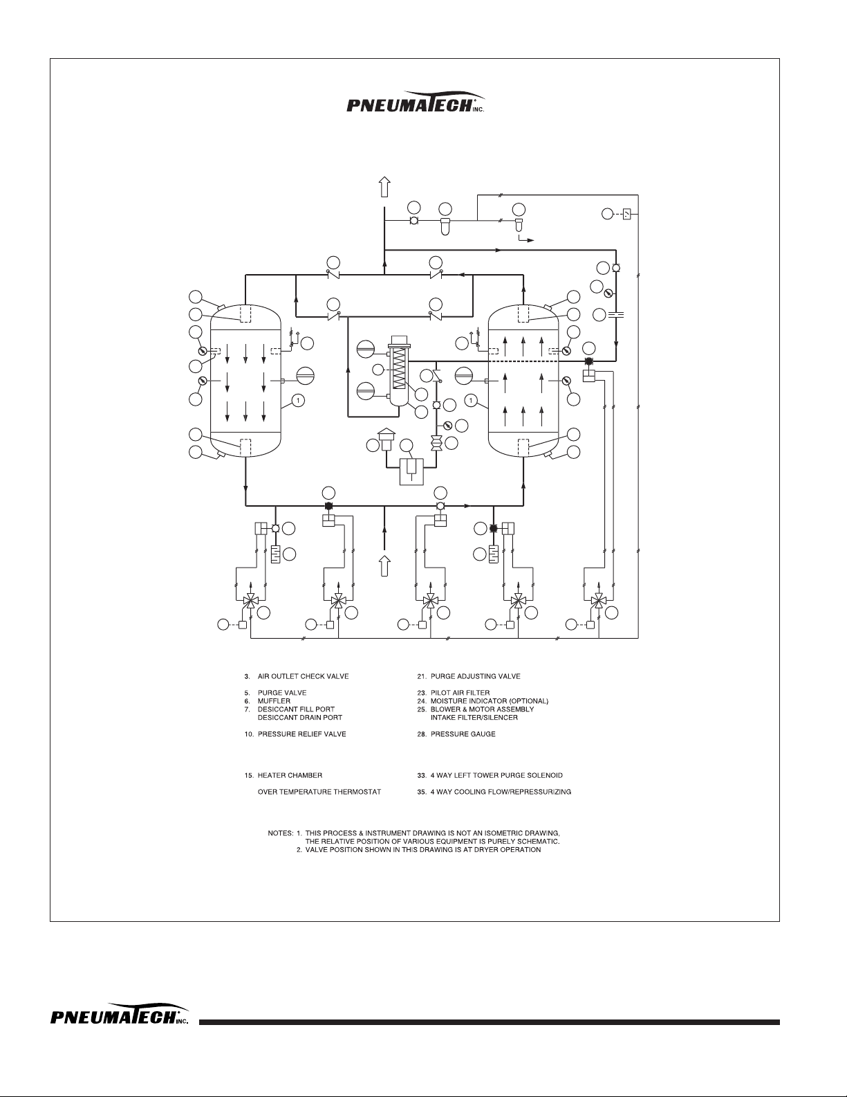
FIGURE 4 — PB SERIES FLOW DIAGRAM
28
S
33
OPEN
EX
98S31S32S
25
EX
65CLOSED
26
CLOSED
EX
65OPEN
9
9
13
10
16
17
OPEN
CLOSED
3
13
15
29
30
10
CLOSED
3
OPEN
AIR OUTLET
23
34
35
S
EX
8
9
CLOSED
18
9
19
20
PILOT AIR LINE
EX (SLIGHT BLEED)
PS1
ESESES
ESESES
ES
TYPICAL PB SERIES
FLOW DIAGRAM
PRESSURE VESSEL
PURGE FLOW CHECK VALVE
8.
9.
DESICCANT SCREEN
PRESSURE GAUGE
TEMPERATURE GAUGE
13.
DESICCANT THERMOSTAT
ELECTRIC HEATER
16.
HEATER CONTROL THERMOSTAT
18.
COOLING FLOW/REPRESSURIZING VALVE
19.
PURGE ORIFICE ASSEMBLY
20.
PURGE ADJUSTMENT PRESSURE GAUGE
PILOT AIR SHUT-OFF VALVE
26.
27.
FLEX CONNECTOR
29.
THROTTLING VALVE
30.
BACK FLOW PREVENTION CHECK VALVE
31.
4 WAY LEFT TOWER SWITCHING SOLENOID
32.
4 WAY RIGHT TOWER SWITCHING SOLENOID
34.
4 WAY RIGHT TOWER PURGE SOLENOID
SOLENOID
THROUGH THE RIGHT TOWER.
EX -
EXHAUST
ES -
ELECTRICAL SIGNAL
PS1 -
LOW PRESSURE SWITCH
FLOW
REGEN
FLOW
DRYING
Page 19

Pub. No. OM-A-10E — April 2004 17
MAINTENANCE
PE & EE SERIES HEAT REACTIVATED AIR
DRYER MAINTENANCE
General
During the first month, clean or replace the pilot air filter
element and repeat periodically. Also clean the exhaust
mufflers. Replace mufflers if the tower pressure gauge
reads any back pressure during the regeneration cycle.
No lubrication is required for any system.
Daily
Check auto drain on prefilter every shift.
Weekly
1. Check the dryer’s sequence of operation, and valve
operation.
2. Check the purge control setting.
3. Check the operating conditions; inlet pressure, inlet
temperature and the flow rate.
4. Check the moisture indicator. BLUE color indicates
DRY conditions. If the color is PINK, refer to the
moisture indicator chart on alarm conditions for
probable cause. (Optional equipment.)
5. Check the purge mufflers for blockage. Possible
indication is back pressure on tower under
regeneration. Replace if necessary.
6. Check the pressure drop across prefilter and afterfilter. Replace the elements when the differential
reaches 5-10 PSID.
Monthly
Check the pilot air filter element. Replace if necessary.
Three Months
1. Every three (3) months, close the purge adjusting
valve momentarily to check for any leaks in the inlet
and/or check valves indicated by air coming
through the exhaust mufflers.
2. Check the prefilter and afterfilter elements for
excessive clogging or possible damage. Replace as
necessary.
3. Blow down relief valves.
4. Check outlet dewpoint conditions.
Twelve Months
1. Close the inlet and outlet valves on the dryer or
bypass the dryer and completely depressurize the
dryer system. Open the desiccant fill port and check
visually. If desiccant is contaminated with oil or
broken, replace the desiccant.
2. Check for leaking check valves per Table 1
symptoms C & D in Troubleshooting Guide. Repair
or replace as necessary.
3. Remove the inlet switching valves and purge exhaust
valves. Clean and replace worn out seats and seals.
4. Check the heater thermostats and heater operation.
Repair or replace as necessary.
5. Inspect the pilot air cylinders for leaks or worn out
seals. Repair or replace as necessary.
6. Check repressurizing valve. Repair or replace as
necessary.
7. Check pilot air solenoid valves for possible defects.
8. Replace diaphragms in valves on economy EE Series
Dryers. See parts list for sizing.
Dewpoint Sensor (Optional)
It is recommended to recalibrate the sensor probe
annually to maintain accuracy. Contact your local
distributor or factory for exchange policy.
Calibration: To maintain accuracy, replace the probe
every two years.
Probe Replacement: Turn the normal/demand selector
switch to the normal position. This will disable the contacts
for Dewpoint Demand. Isolate and depressurize the probe
chamber. Remove, and replace the probe. Pressurize the
probe chamber and connect the sensor cable. A small
amount of sample air (approximately 2-10 SCFH) should
expel out the chamber needle valve.
Disconnect power and depressurize the
dryer completely before starting maintenance procedures.
Page 20
18 Pub. No. OM-A-10E — April 2004
Mufflers
Purge mufflers are installed to reduce the noise level. The
mufflers tend to plug up and increase back pressure over
time due to oil carryover and contaminants from
compressor, or due to desiccant dust at the initial start-up.
To eliminate back pressure, replace muffler after three
months, or when the back pressure increases in the
regenerating tower.
PB SERIES HEAT REACTIVATED BLOWER
PURGE AIR DRYER MAINTENANCE
General
During the first month clean or replace the pilot air filter
element and repeat periodically. Also clean the exhaust
mufflers. Replace mufflers if the tower pressure gauge
reads any back pressure during the regeneration cycle.
No lubrication is required for any system.
Check intake filter on the blower, replace if necessary.
Daily
Check auto drain on prefilter every shift.
Weekly
1. Check the cooling flow pressure setting.
2. Check the dryer’s sequence of operation and valve
operation.
3. Check the operating conditions; inlet pressure, inlet
temperature and the flow rate.
4. Check the moisture indicator. BLUE color indicates
DRY conditions. If the color is PINK, refer to the
moisture indicator chart on alarm conditions for
probable cause.
5. Check the purge mufflers for blockage. Possible
indication is back pressure on tower under
regeneration. Replace if necessary.
6. Check the pressure drop across prefilter and afterfilter. Replace the elements when the differential
reaches 5-10 PSID.
Monthly
1. Check the pilot air filter element. Replace if
necessary.
2. Check the blower intake filter. Replace if necessary.
Three Months
1. Every three (3) months, check for any leaks in the
inlet and/or check valves indicated by air coming
through the exhaust mufflers when the blower is off.
2. Check the prefilter and afterfilter elements for
excessive clogging or possible damage. Replace as
necessary.
3. Blow down relief valves.
4. Check outlet dewpoint conditions.
Twelve Months
1. Close the inlet and outlet valves on the dryer or
bypass the dryer and completely depressurize the
dryer system. Open the desiccant fill port and check
visually. If desiccant is contaminated with oil or
broken, replace the desiccant.
2. Check for leaking check valves per Table 1
symptoms C & D in Troubleshooting Guide. Repair
or replace as necessary.
3. Remove the inlet switching valves and purge exhaust
valves. Clean and replace worn out seats and seals.
4. Inspect the pilot air cylinders for leaks or worn out
seals. Repair or replace as necessary.
5. Check repressurizing valve. Repair or replace as
necessary.
6. Check pilot air solenoid valves for possible defects.
Dewpoint Sensor (Optional)
It is recommended to recalibrate the sensor probe
annually to maintain accuracy. Contact your local
distributor or factory for exchange policy. See Page 17 for
calibration and sensor probe replacement information.
Mufflers
Purge mufflers are installed to reduce the noise level. The
mufflers tend to plug up and increase back pressure over
time due to oil carryover and contaminants from
compressor, or due to desiccant dust at the initial start-up.
To eliminate back pressure, replace muffler after three
months, or when the back pressure increases in the
regenerating tower.
Disconnect power and depressurize the
dryer completely before starting maintenance procedures.
Page 21
Pub. No. OM-A-10E — April 2004 19
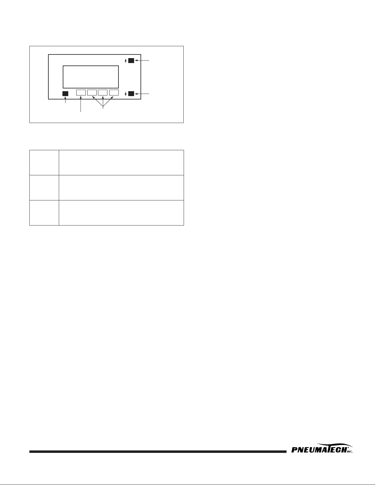
DEWPOINT DISPLAY KEY FUNCTIONS
FIGURE 5 — DIGITAL DISPLAY
There are 3 buttons on the front of the hygrometer:
SETPOINT PROGRAMMING
(Setpoints are factory preset)
Standard Settings
1. Press PROG and (↓) buttons simultaneously to enter
into the Setpoint Setting Mode.
2. SP1 Adjust value for the Setpoint 1, press PROG to
continue. SP1 set at -40°F (Dewpoint Demand).
3. SP2 Adjust value for the Setpoint 2, press PROG
several times to exit. SP2 set at -20°F (High Humidity
Alarm).
4. SP3 Not used.
Settings for models with Low Dewpoint option
1. SP1 set at -90°F (Dewpoint Demand)
2. SP2 set at -60°F (High Humidity Alarm)
3. SP3 Not used.
Settings for models with Pulse Purge Regeneration (PPR)
option
1. SP1 set at -50°F (Dewpoint Demand)
2. SP2 set at -40°F (Standard Cycle Mode)
3. SP3 set at -20°F (High Humidity Alarm)
OPEN SENSOR CONDITION
When message oPEn1 is displayed, the dewpoint sensor
is likely to be disconnected from the hygrometer.
SETPOINT LIMIT INDICATION
Setpoint limit message is the flashing number within
operating range of the hygrometer.
OVER RANGE AND UNDER RANGE
INDICATION
For Ceramic Sensor Probes:
1. When the hygrometer detects the maximum value of
the Measurement range, +68°F flashes on the
display.
2. When the hygrometer detects the minimum value of
the Measurement range, -148°F flashes on the
display.
For Aluminum Oxide Sensor Probes (Dryers built prior to
Year 2000):
1. When the hygrometer detects the maximum value of
the Measurement range, -13°F flashes on the
display.
2. When the hygrometer detects the minimum value of
the Measurement range, -112°F flashes on the
display.
PEAK/VALLEY INDICATION
1. Press (↑) several times to get message PEAK and the
value flashing.
2. Press (↓) several times to get message VALY and the
value flashing.
3. Press (↓) and (↑) simultaneously to reset the Peak or
Valley value while displayed.
Prog. Used to enter Programming Mode, to scroll
through setup prompted, or to enter a
selection or value into memory.
↑↑
↑↑
Used to increase a displayed value. Press and
hold this button to increase the displayed
value.
↓↓
↓↓
Used to decrease a displayed value. Press
and hold this button to decrease the
displayed value.
DIGITAL DISPLAY KEY FUNCTIONS
BUTTON
-73.5F
Prog.
PROGRAM
BUTTON
OS SP1 SP2
OPEN SENSOR
ANNUNCIATOR
SP3
SETPOINT
ANNUNCIATORS
BUTTON
Page 22
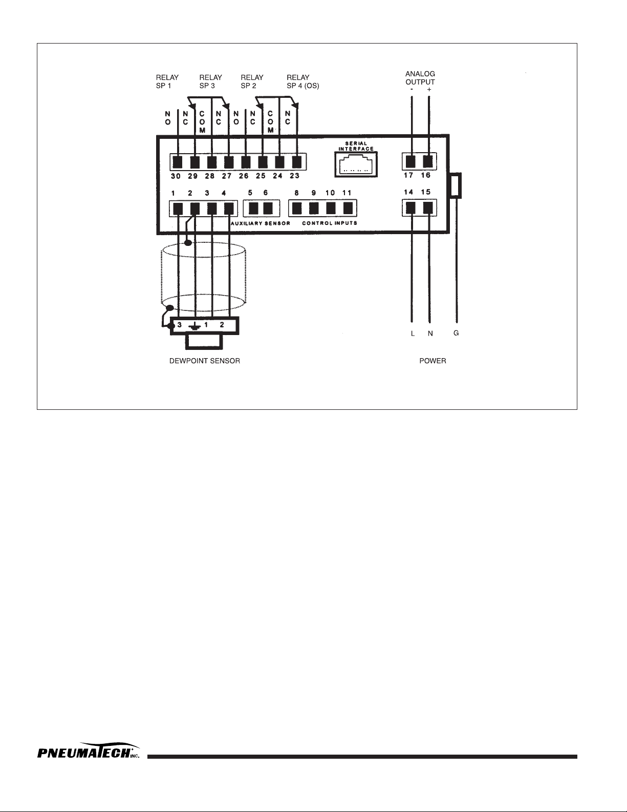
20 Pub. No. OM-A-10E — April 2004
FIGURE 6 — DEWPOINT DISPLAY CONTROL WIRING
Page 23

Pub. No. OM-A-10E — April 2004 21
OPTIONS LISTING WITH EXPLANATION
AUDIBLE ALARM
The Audible Alarm consists of a buzzer with reset push
button and ON/OFF selector switch.
The audible alarm provides an audible warning to alert
an operator that the dryer is not functioning properly. This
option is used with options such as “Failure to Shift Alarm”
or “High Humidity Alarm.”
FAILURE TO SHIFT ALARM
The Failure to Shift Alarm consists of an alarm light that
illuminates if the desiccant towers fail to shift at a
prescribed time. Dry contacts are provided for remote
annunciation.
HEATER FAILURE ALARM
The Heater Failure Alarm consists of an alarm light that
illuminates if the heater fails to reach design temperature
during regeneration. The time delay relay shall be set at
3 hrs. and the thermostat set at 200°F. Dry contacts are
provided for remote annunciation.
HIGH HUMIDITY ALARM
The High Humidity Alarm consists of an alarm light
controlled by a hygrometer that senses the dewpoint at the
outlet of the air dryer. This alarm illuminates when the
dewpoint reaches -20°F and above. A small amount of
sample air is required for operation. Dry contacts are
provided for remote annunciation.
Calibration: To maintain accuracy, replace the probe
every two years.
Probe Replacement: Turn the normal/demand selector
switch to the normal position. This will disable the contacts
for Dewpoint Demand. Isolate and depressurize the probe
chamber. Replace the probe. Pressurize the probe
chamber and turn the power back on.
MOISTURE INDICATOR
The moisture indicator consists of a small, clear,
polycarbonate filter filled with a color change silica gel. It
is located at the outlet of the dryer. When the dewpoint is
below -10°F, the desiccant is blue. When the dewpoint is
above -10°F, the desiccant is pink. A small amount of
sample air is required for operation.
FIGURE 7 — MOISTURE INDICATOR
OVER/HI TEMPERATURE ALARM
The Over/Hi Temperature Alarm consists of an alarm light
that illuminates when the temperature at the inlet of the
heater shell exceeds 200°F. Probable cause for this would
be reduced purge flow or no purge flow during the
heating cycle. Dry contacts are provided for remote
annunciation.
PANEL LIGHTS
The Panel Light option consists of four lights: Left Tower
Drying, Right Tower Drying, Left Tower Regenerating, and
Right Tower Regenerating. These lights are for dryer
sequence indication.
PLC CONTROLLER
PLC Controller is standard on PB series Blower Purge
dryers and with Pneumatech’s Pulse Purge Regeneration
option. It can also be added to control the operation of
standard regenerative dryers. Typically Square D or Allen
Bradley PLCs are used.
FILTER
HOUSING
SILICA GEL
Page 24

22 Pub. No. OM-A-10E — April 2004
DEWPOINT DEMAND CONTROL “DPD”
The Dewpoint Demand control is an energy saver that can
extend the drying cycle without purging, during periods of
lower moisture loads. The Dewpoint Demand system
offers, in one compact package, the utmost in flexibility
and accuracy sensing the actual dewpoint of the outlet air.
The hygrometer senses the dewpoint at the outlet of the
dryer at the end of the drying cycle, and extends the
drying cycle until the preset adjustable dewpoint setpoint
is reached. During this extended drying cycle, the purge
valves are closed and the opposite tower is pressurized
and prepared for the drying cycle. The dewpoint demand
option reduces purge loss and extends valve life. This
option consists of the following:
• Digital Dewpoint Display
• Adjustable Setpoints
• Demand Cycle Light
• High Humidity Alarm Light with Dry Contact
• 4-20mA Output
Calibration: To maintain accuracy, the probe should be
recalibrated annually. Recalibrated probes are
available through your local distributor.
Probe Replacement: Isolate and depressurize the
probe chamber. Disconnect the sensor cable from the
sensor. Remove, and replace the probe. Pressurize the
probe chamber and connect the sensor cable. A small
amount of sample air (approximately 2-10 SCFH) should
expel out the chamber needle valve.
PULSE PURGE REGENERATION (PPR) WITH
DEWPOINT DEMAND (DPD)
(PE & EE Series only)
Pulse Purge Regeneration systems use the same NEMA
cycle of 8 hours as PE & EE Series dryers except during
the regeneration cycle, instead of continuously flowing 7%
of the purge air and blowing it out into the atmosphere,
the purge air is cycled at 30 minute intervals during the 4
hour regeneration period. It is observed that this method
of purging and holding greatly enhances the regeneration
process and considerably reduces the period the heater is
energized, and also cuts down the purge flow by
approximately 50%, since purging and holding during the
regeneration cycle is equal.
Pulse Purge Regeneration (PPR) with Dewpoint Demand is
designed to achieve the maximum energy savings benefits
of Pulse Purge at loaded conditions. At low load
conditions, Dewpoint Demand takes over for added
energy savings. The amount of time that the unit is in
demand is proportional to the moisture load. This cycle is
only recommended for continuous operation.
This system is controlled by a PLC which has a nonvolatile
memory. The program is stored in the E-PRom memory.
A dewpoint monitor with High Humidity Alarm and three
hour meters are provided to monitor the system and show
savings. The hour meters display “Heater Run Time”,
“Dryer Run Time” and “Demand Time”.
Page 25

Pub. No. OM-A-10E — April 2004 23
TROUBLESHOOTING
Table 1 — Troubleshooting Guide for Regenerative Dryers
Symptoms Cause Remedy
A. Elevated Dewpoint. 1. Low purge flow.
2. Low inlet pressure.
3. Excess moisture carryover.
4. High inlet temperature.
5. Excess air/gas inlet flow.
6. Desiccant coated with oil.
7. Regeneration temperature low.
8. Dewpoint monitor out of
calibration.
1. Reset purge pressure at the
recommended pressure.
2. Recalculate purge pressure setting
from the chart.
3. Check prefilter element. Check
drains at prefilter and afterfilter.
4. Check aftercooler operation.
5. Check total output of compressors.
6. Depressurize dryer and inspect
desiccant.
7. *See B.
8. Recalibrate probe.
B. Regeneration temperature low
(Normal 250°F).
1. Thermostat faulty or set too low.
2. Low purge flow.
3. Back pressure on regenerating
tower.
4. Heater burnout.
5. Contactor faulty.
6. No power.
7. Insufficient heating period.
1. Reset thermostat or replace if
necessary.
2. *See A1.
3. *See C1.
4. Check heater, replace if
necessary.
5. Replace heater contactor.
6. Check for continuity.
7. (Contact factory).
C. High back pressure on regenerat-
ing tower.
NOTE: The tower should be at ‘0’
PSIG during regeneration cycle. Any
back pressure will result in improper
regeneration.
1. Muffler plugged.
2. Check valves leaking.
NOTE: To test for leaking check valves
during regeneration cycle, shut the
purge adjusting valve. If gas is still
passing through, it is an indication of
leaking check valves.
3. Excess purge flow.
4. Restricted purge exhaust piping.
5. Too high purge.
6. Diaphragms ruptured in values
(EE models).
1. Replace mufflers.
2. Repair or replace faulty check
valves.
3. Check and reset the purge
pressure.
4. Remove obstruction or replace
with larger size pipe.
5. Check purge calibration, plot and
reset.
6. Replace diaphragms.
Page 26

24 Pub. No. OM-A-10E — April 2004
D. Excessive flow through mufflers. 1. Check valves leaking.
NOTE: To test for leaking, check valves
during regeneration cycle, shut the
purge adjusting valve. If gas is still
passing through, it is an indication of
leaking check valves.
2. Inlet valves did not switch.
3. Purge valve stays open.
4. Repressurizing valve does not
close.
5. Diaphragms ruptured in valves
(EE models).
1. Repair or replace faulty check
valves.
2. See F1 to F4.
3. Check purge solenoid and valve.
Repair or replace faulty purge
valve or solenoid.
4. Check repressurizing solenoid
and valve. Repair or replace faulty
repressurizing valve or solenoid.
5. Replace diaphragms.
E. No gas flow through the dryer. 1. Both inlet valves closed due to low
inlet pressure.
1. Manually open the inlet valve by
turning the shaft or the ON
actuator.
F. Failure to switch alarm light. 1. Inlet valves did not switch.
2. Faulty timer.
3. Insufficient pilot air pressure.
4. Cylinder leaking or seized up.
1. Check pilot air solenoid valve.
Repair if necessary.
2. Replace timer.
3. Clean or replace pilot filter
element.
4. Repair or replace pilot air
cylinder.
G. High pressure drop in dryer. 1. Desiccant retainer screens
plugged.
2. Excess flow.
3. High purge flow.
4. Purge valve stays open.
5. Repressurizing valve stays open.
1. Replace desiccant retainer
screens.
2. Check inlet flow conditions.
3. Check and reset purge pressure.
4. Check repressurizing solenoid
valve, repair or replace if
necessary. Check timer.
5. See D4.
H. Dryer fails to purge. 1. Orifice plate plugged.
2. Purge valve fails to open.
3. Purge valve closed.
4. Purge check valve blocked.
1. Clean the orifice plate.
2. See G3.
3. Reset proper purge pressure.
4. Inspect purge check valve.
Replace if necessary.
I. High dewpoint alarm light. See chart on alarm conditions.
J. Moisture indicator color turned pink
(wet conditions).
1. Bleed valve closed.
2. See probable cause on #1.
1. Open the bleed valve to allow
small amount of air to constantly
flow through the gel.
K. Tower fails to pressurize. 1. Purge valve stays open.
2. Repressurizing valve faulty.
3. Diaphragms ruptured in valves
(EE models).
1. See G3.
2. See D4.
3. Replace diaphragms.
Table 1 — Troubleshooting Guide for Regenerative Dryers, continued
Symptoms Cause Remedy
Page 27

Pub. No. OM-A-10E — April 2004 25
L. Tower does not pressurize fully. 1. Inlet pressure low.
2. Purge pressure too low.
3. Repressurizing period too short.
1. Calibrate and plot purge pressure
and reset.
2. Reset proper purge pressure.
3. Check timer sequence of
operation.
M. Excess desiccant dust.
NOTE: If the regenerating tower does
not pressurize fully, desiccant attrition
takes place at the time of tower switchover.
1. See K & L.
2. Excess flow due to greater
demand in process or addition of
extra compressors.
2. Check outlet flow.
N. Dewpoint Spike.
NOTE: Blower purge dryers may spike
during normal operation due to blower
cooling.
1. Excessive residual heat in newly
regenerated tower.
1. Lower heater thermostat settings.
Table 1 — Troubleshooting Guide for Regenerative Dryers, continued
Symptoms Cause Remedy
Page 28

LIMITED WARRANTY
Warranties and Limitation of Liability: Pneumatech/ConservAIR (“the Company”) warrants that it will, in its
sole discretion, either repair or replace Products and/or Components of Products sold by it which have defects in
material or workmanship (covering Components and reasonable labor) provided: (a) Customer notified the
Company of any claim of defect in material or workmanship within fourteen (14) months from date of shipment
from the Company’s factory or twelve (12) months from the date of initial operation of Product, whichever occurs
first; (b) Customer holds the Product or Component for inspection by the Company’s representative; (c) Customer
returns the Product(s) or Component(s) only with Company authorization, within thirty (30) days after such
authorization, with transportation charges prepaid and shipped pursuant to the Company’s directions; and (d) the
Product(s) or Component(s) are found defective in materials or workmanship upon examination by the Company.
Products or Components shall not be considered defective if they substantially fulfill performance requirements set
forth in the Company literature and are manufactured in accordance with the Company’s specifications or
government specifications when applicable. Replacement / spare Components will be warranted for six (6)
months from the date of shipment from the Company’s factory, or for the balance of the original warranty period
(or extended warranty period, if registered, see below), whichever is longer.
Available Extended Warranty: In addition to the above warranty, if the Customer registers the warranty of a
standard price book Pneumatech dryer or a standard price book ConservAIR Intermediate Control
®
(“Specified
Products”) via the internet at www.pneumatech.com or www.conservair.com: (i) the above warranty will
be extended to twenty-four (24) months from the date of shipment from the Company’s factory (covering
Components and reasonable labor) as to such Specified Products and (ii) the Company warrants that it will, in its
sole discretion, either repair or replace heat exchangers on refrigerated dryers and valves on PH, PE, PB or PHC
style regenerative dryers and valves on Intermediate Controls
®
for defects in material or workmanship (covering
Components only) provided: (a) Customer notified the Company of any claim of defect in material or
workmanship within sixty (60) months from date of shipment from the Company’s factory; (b) Customer holds the
Product or Component for inspection by the Company’s representative; (c) Customer returns the Component(s) only
with Company authorization, within thirty (30) days after such authorization, with transportation charges prepaid
and shipped pursuant to the Company’s directions; and (d) the Component(s) are found defective in materials or
workmanship upon examination by the Company. Components shall not be considered defective if they
substantially fulfill performance requirements set forth in the Company literature and are manufactured in
accordance with the Company’s specifications or government specifications when applicable. These extended
heat exchanger and valve warranties cover only parts, not labor, and are not pro-rated in any way.
The warranties stated herein will not extend to Products or Components that: (a) have been subject to misuse,
neglect, accident, or that have been repaired or altered by, or at the direction of Customer, without the Company’s
written authorization, or (b) have not been maintained or installed by Customer pursuant to the Company’s
guidelines. The Company shall not be liable for any expense, liability or loss incurred by Customer nor for any
special, consequential, liquidated or other damage or penalties suffered by Customer or anyone else with respect
to any Product or Component.
There are no warranties which extend beyond the warranties stated herein. The
foregoing warranty is in lieu of all other warranties whether expressed, implied or
statutory, including implied warranties of merchantability or fitness for any
particular purpose. No representation or warranty of any person on behalf of the
Company shall extend the liability or responsibility of the Company beyond the
terms of the warranties stated herein. In no event shall the Company be liable for
any loss of profits, loss of use, incidental, consequential or special damages to any
person or company resulting from the use of the Company Products.
4909 70th Avenue
Kenosha, WI 53144
Phone: 262-658-4300
Fax: 262-658-1945
www.pneumatech.com
 Loading...