

Page 1
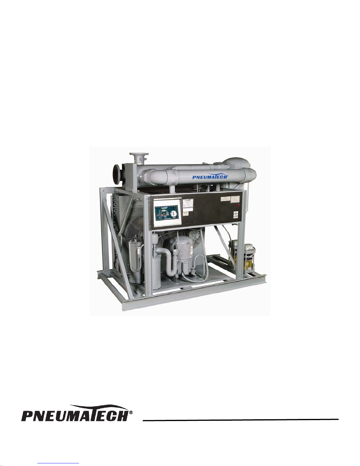
Noncycling Refrigerated Air Dryers
AD-750 to 4000 Series
Owner’s Manual
9829 2103 73 August 2009
Page 2
DATE OF PURCHASE
MODEL
SERIAL NO.
Record above information from nameplate.
Retain this information for future reference.
1
Page 3

TABLE OF CONTENTS
General Information......................................................................................................3
Inspection ..........................................................................................................3
Safety Instructions .............................................................................................3
Disclaimer of Warranty.......................................................................................3
Installation Instructions .................................................................................................4
Start-Up and Operation.................................................................................................7
Design Conditions..............................................................................................7
Start-Up Procedure ............................................................................................7
Operating Range and Control Settings ..............................................................8
Digital Dry Guard™ (DDG) Controller Operation ...............................................9
Shutdown Procedure .........................................................................................10
Operating Conditions .........................................................................................10
Maintenance .................................................................................................................11
Air Dryer Maintenance .......................................................................................10
Automatic Drains................................................................................................10
Compressor .......................................................................................................13
Expansion Valve ................................................................................................13
Hot Gas Bypass Valve .......................................................................................13
Refrigerated Air Dryer Service Check List ....................................................................17
Troubleshooting............................................................................................................18
2
Page 4
GENERAL INFORMATION
The Pneumatech Air Drying System is designed to cool
and remove moisture from compressed air. When
properly installed, the unit requires little maintenance or
adjustment.
WARNING
Do NOT install, operate, maintain, adjust or service
this unit without thoroughly reading this manual.
This manual contains important safety information. Read
THOROUGHLY and follow the Safety Instructions
provided in this manual and posted on the unit. Keep this
manual near the unit and in a safe place. Replace this
manual if it becomes torn or dirty and cannot be properly
used.
Please read the Installation Instructions and Start-up and
Operation sections of this manual before attempting to
operate the unit.
Please read the Maintenance and Troubleshooting
sections of this manual before beginning any
maintenance or service work on this unit.
INSPECTION
Inspect equipment. Any concealed shipping damage
must be reported to the carrier immediately. Damage
claims should be filed by the consignee with the
carrier.
SAFETY INSTRUCTIONS
3. USE SUITABLE PARTS & ACCESSORIES
Do not use air pressurized accessories or parts in
the air system not suitable for the maximum air
pressure.
4. RELEASE AIR PRESSURE SLOWLY
Fast moving air will stir up dust and debris, which
may be harmful. Release air pressure slowly when
depressurizing your system to avoid bodily injury.
5. SECURE DRAIN LINES
Fasten drain lines to floor or drain. Pressurized air
may periodically pass through drain lines, which will
cause an unsecured line to whip and may cause
bodily injury.
WARNING
Air from compressor and from Pneumatech Air
Drying System, as equipped, is not safe for human
respiration (breathing).
To provide safe, breathable air, compressor must be
capable of producing at least Grade D breathing air as
described in Compressed Gas Association Commodity
Specification G7.1-1966. Special filtering, purifying and
associated alarm equipment must be used to convert
compressed air to “Breathing Air.” Other special
precautions must also be taken.
Refer to OSHA 29 CFR 1910.134.
DISCLAIMER OF WARRANTY
When using air compressors and compressed air
accessories, basic safety rules and precautions must
always be followed, including the following:
1. READ ALL INSTRUCTIONS FULLY.
2. WIRING & BREAKERS
Wiring, breakers and other electrical equipment must
conform to local and national electrical codes. Do
not operate this unit with damaged wiring or after the
unit or air handling parts have been dropped or
damaged in any manner. Notify authorized service
facility for examination, repair or other adjustments.
3
If this unit is used to produce breathing air, the special
equipment and precautions expressed in OSHA 29 CFR
1910.134 for specifications of the necessary equipment
and special precautions to make Breathing Air MUST BE
used or any warranties are VOID and manufacturer
disclaims any liability whatsoever for loss, personal
injury or damage.
Page 5
INSTALLATION INSTRUCTIONS
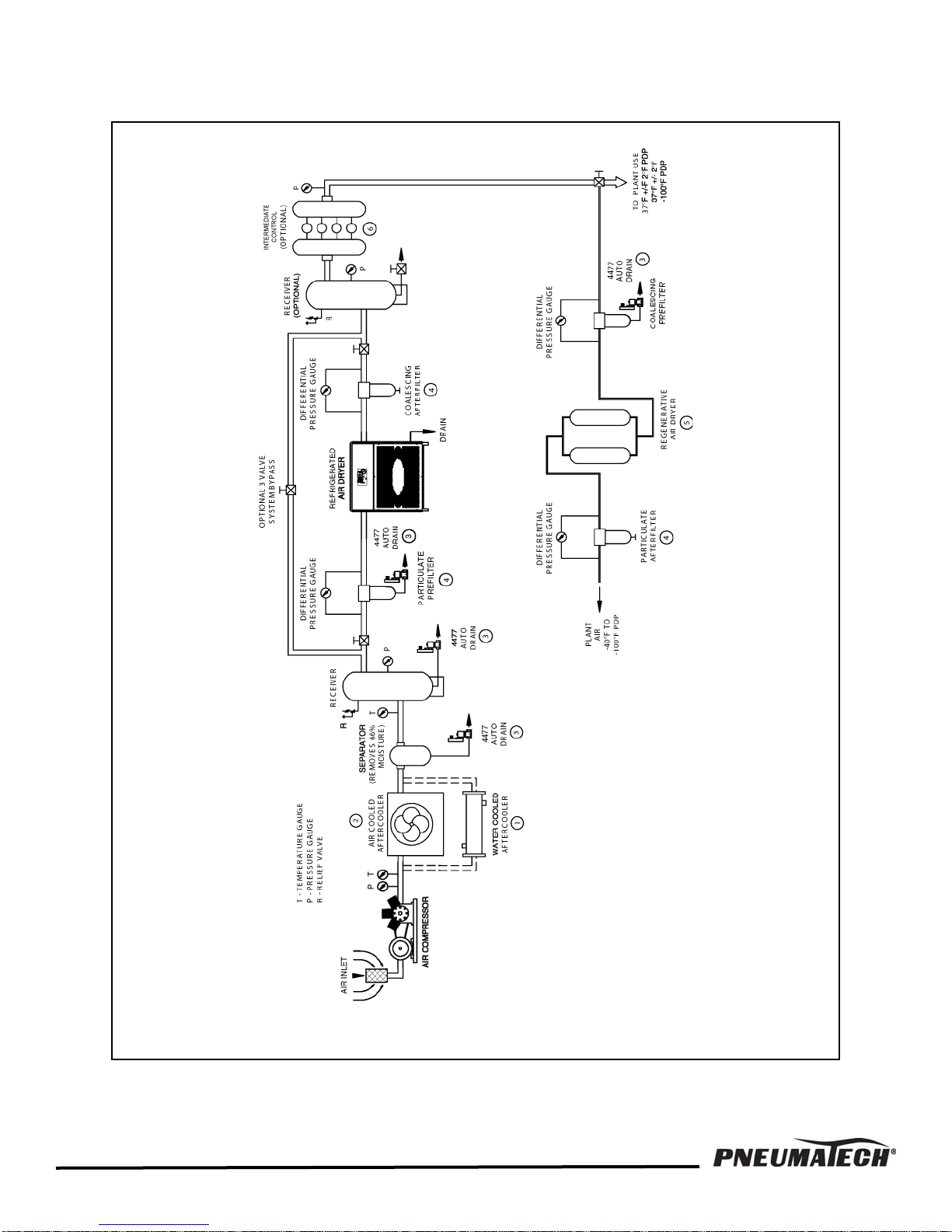
FIGURE 1 — COMPRESSED AIR SYSTEMS RECOMMENDED INSTALLATION FLOW DIAGRAM
4
Page 6
A. Install the dryer INDOORS in an area where the
ambient temperature will be above 55°F (13°C) and
below 100°F (38°C). Temperatures below 55°F
(13°C) and above 100°F (38°C) may cause erratic
operation of the air dryer. Air-cooled dryers must be
installed INDOORS in a location with proper
ventilation which will maintain ambient temperatures
as specified above.
B. Position the dryer to permit free circulation of cooling
air through the condenser. Keep two feet minimum
clearance space around the dryer, and also on the
top for servicing. Lack of ventilation can build up the
room temperature by recirculating the same cooling
air through the condenser over and over again. This
will eventually shut down the refrigerant compressor
on high head pressure and/or on internal overload.
C. Connect the compressed air to the dryer inlet.
Connect the plant compressed air line to the dryer
outlet. A three-valve bypass around the dryer is
recommended for dryer service. See Figure 1. A
coalescing afterfilter is recommended for oil-flooded
air compressor systems.
D. Make sure when piping is in place that no undue
stress is placed on dryer connections. Union joints
or flexible connections are recommended to relieve
stress. Also, properly support the pipes as needed
with hangers or brackets. Air piping must be
installed by an experienced pipefitter.
E. An aftercooler (air-cooled or water-cooled) must be
installed between the air compressor and the dryer.
Installing the dryer without the proper aftercooler will
bring high inlet temperature compressed air to the
air dryer which will cause premature failures.
Aftercoolers must be followed by a separator and an
automatic drain to remove the condensed moisture
before the compressed air reaches the air dryer.
If the condensed water is not removed at the
aftercooler/separator/drain, it will reduce the cooling
capacity of the air dryer. Aftercoolers will condense
approximately 2-1/2 to 3 times more water than that
of the air dryer.
F. For models AD-750 through AD-3200, electronic
timer operated drains are standard. All dryers
include a particle strainer upstream from the drain
valve. To clean, close the shut-off valve and
depressurize the drain line.
All drain outlets may be combined for condensate
disposal. Dispose the condensate in compliance to
local and federal government requirements.
WARNING
Drain outlet tubing will periodically contain
pressurized air. An unsecured drain tube will whip
around potentially causing bodily injury.
CAUTION
Do not combine any two or more drain inlet lines
through one single automatic drain valve. This will
reduce or eliminate the proper drainage.
G. For water-cooled air dryers, connect cooling water
lines to the water-cooled condenser from the water
supply. Water pressure must be a minimum of 35
PSIG. Do not connect city water to a condenser
which is piped for tower water or vice versa.
Strainers are recommended at the water inlet to the
condenser. Proper chemical treatment is
recommended for cooling tower water to avoid
scaling and sludge inside the condenser.
CAUTION
Do not reduce pipe sizes connected to water and
drain lines. They should be the same or larger than
sizes supplied on the dryer to avoid excess pressure
drop.
5
Page 7
H. Connect electric power, according to the wiring
diagram and nameplate power requirements, to the
electrical terminals. The refrigerated dryer is
designed to run continuously; therefore, it must be
wired separately from the air compressor cycling
switch. The dryer must not cycle with the air
compressor. All units are prewired internally.
Follow the recommendation on the electrical drawing
for the fuse size and the incoming power details.
Connect the power to the air dryer only through a
properly sized fused disconnect switch.
WARNING
Wiring to the dryer must meet the national (NEC) and
local code requirements. Check the voltage
specified on the nameplate to the electrical power
connecting to the dryer. Electrical connections must
be made by a qualified electrician.
CAUTION
SCROLL COMPRESSOR
Air dryers with a scroll compressor are
unidirectional and to function properly they must be
phased correctly. To turn the compressor clockwise,
use a phase sequence indicator to determine phases
A, B, & C. For proper compressor rotation, connect
the power supply phases A to L1, B to L2, & C to L3.
Reverse rotation may damage the compressor. If the
compressor is wired backwards the compressor will
be noisy, vibrate excessively and the oil sump will
become warm. The suction pressure will begin to
rise, and the discharge pressure will fall.
6
Page 8
START-UP AND OPERATION
The non-cycling design of the refrigerated dryer assures
proper dew point control at all load conditions. The
refrigerant compressor runs continuously when the dryer
is “ON”. All dryers are installed with fan cycling switches.
These fans will cycle with respect to the load changes,
ambient temperature fluctuations, and the cleanliness of
the condenser. Standard units are designed to operate
under the following conditions:
DESIGN CONDITIONS
1. Inlet Air Temperature:
100°F (38°C) design 120°F (49°C)maximum
2. Inlet Air Pressure:
100 PSIG design 150 PSIG maximum
3. Ambient Air Temperature:
55°F (13°C) minimum 100°F (38°C) maximum
4. Cooling Water Temperature:
90°F (32°C) maximum
5. Cooling Water Pressure:
35 PSIG minimum 100 PSIG maximum
At temperatures above the 100°F (38°C) design,
refrigeration capacity will decrease. Operating air
pressures below the 100 PSIG design will reduce
system capacity.
START-UP PROCEDURE
1. If the suction pressure gauge reads zero, refrigerant
loss has occurred. Call the factory or distributor for
service.
CAUTION
CRANKCASE HEATER
Air dryers with three-phase power supply are
equipped with a compressor crankcase heater. This
heater must be energized by closing the disconnect
switch a minimum of 6 to 10 hours before start-up.
Power to the air dryer can be left on to energize the
crankcase heater for off-cycle, during evening or
weekend shutdowns (except scroll compressors).
STARTING THE DRYER WITHOUT ENERGIZING THE
CRANKCASE HEATER WILL CAUSE PREMATURE
FAILURE OF THE REFRIGERANT COMPRESSOR.
Failure to comply with procedure of energizing
crankcase heater before start-up may void warranty.
2. Check the temperature on the crankcase of the
3. For water-cooled Air Dryers (ADW) make sure the
4. For open frame design units [Models AD(W)-1500 &
5. Turn the power ON/OFF switch to the ON position.
6. The suction pressure will gradually come down to
CAUTION
compressor to make sure the crankcase heater is
working before starting the dryer.
water supply (Minimum Pressure 35 PSIG) is
available at the condenser inlet. The water
regulating valve will modulate and control the water
flow with respect to the dryer load conditions. The
water-cooled condenser drain plug (located inside
enclosure) must be installed.
larger], the following valves must be open prior to
start-up. All valves are tagged with specific
instructions.
a. Compressor isolation valves (suction &
discharge service valves).
b. Receiver valve(s) (air-cooled models only).
c. Condenser outlet liquid line valve (water-cooled
models only).
d. Hot gas line valve – Models AD(W)-2500 &
larger. Located on the hot gas line before the Hot
Gas Bypass Valve.
e. Liquid line valve on water-cooled condenser
outlet (water-cooled models only).
the blue or green range depending on the type of
refrigerant used in the air dryer. Check the
refrigerant suction pressure gauge reading. If the
suction pressure is above or below the suggested
color range, a hot gas bypass valve adjustment is
required. (Refer to the Hot Gas Bypass Valve
section of this manual.) For proper operating range
and control settings see listing below.
7
Page 9

7. The Expansion valve is factory set for the correct
superheat of 8 to 10°F (-13 to -12°C) and should not
be re-adjusted. If any malfunction is noticed on the
expansion valve, contact the factory or your
Pneumatech distributor.
8. Allow 10 to 15 minutes of cool down time before
adding the compressed air load.
9. Keeping the dryer outlet isolation valve closed,
pressurize the dryer to the line pressure. See
Figure 1.
10. Check for any leaks in the system.
11. Slowly open the dryer outlet isolation valve to
pressurize the downstream system.
OPERATING RANGE AND
CONTROL SETTINGS
R-134a
Refrigerant Suction Pressure:
25 to 33 PSIG - Blue color range
Refrigerant Discharge Pressure:
75 to 170 PSIG Air-cooled units
115 to 135 PSIG Water-cooled units
Refrigerant Low Pressure Switch:
Cut Out 20 PSIG
Cut In 40 PSIG
Refrigerant High Pressure Switch:
250 PSIG Air-cooled units
225 PSIG Water-cooler units
Fan Control:
Cut Out 110 PSIG
Cut In 150 PSIG
R-404a
Refrigerant Suction Pressure:
69 to 76 PSIG - Orange color range
Refrigerant Discharge Pressure:
235 to 272 PSIG
Refrigerant Low Pressure Switch:
Cut Out 58 PSIG
Cut In Manual reset
Refrigerant High Pressure Switch:
425 PSIG Air-cooled units
385 PSIG Water-cooled units
Fan Control #1:
Cut Out 215 PSIG
Cut In 280 PSIG
Fan Control #2:
Cut Out 225 PSIG
Cut In 295 PSIG
Consult factory for pressure switch settings on dryers
equipped with optional Low Ambient Headmaster
control.
8
Page 10
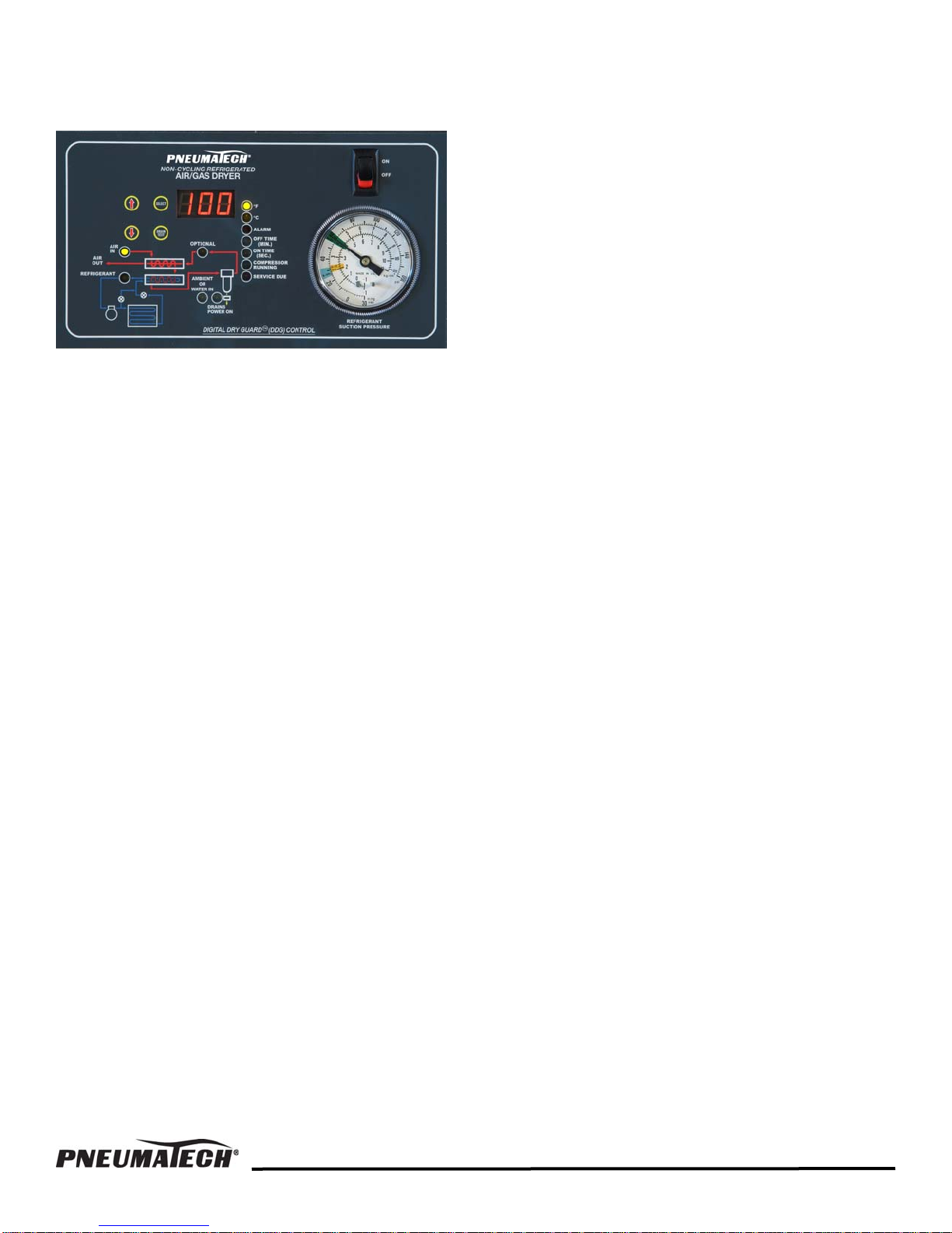
DIGITAL DRY GUARD™ (DDG)
CONTROLLER OPERATION
(Available on some models as standard, and others as
an option.)
The DDG Controller is capable of 4-channel temperature
display, drain control, and service due and alarm
indication.
Temperature Display
The DDG controller is capable of 4-channel temperature
display. The unit displays refrigerant suction temperature
(measured immediately downstream from the refrigerant/
air heat exchanger), incoming air temperature, ambient
air temperature (or incoming water temperature for units
with a water-cooled condenser), and dew point
temperature (optional). Only one temperature can be
displayed on the LCD screen at a time. In the normal
operational mode, pushing the UP (↑) or DOWN (↓)
arrow keys will cycle the temperature displayed, while
LEDs on the DDG unit indicate which temperature is
being displayed. Pushing the SELECT key will cycle
between Fahrenheit and Celsius temperature scales.
The LED labeled “OPTIONAL” corresponds to the dew
point temperature. If your unit does not include this
option, the temperature displayed when the “OPTIONAL”
LED is lit will be about 30°F (-1°C) by default. This does
NOT indicate that the dew point is actually 30°F (-1°C).
Drain Operation
Locking/Unlocking Drain Time Settings: The ON
TIME and OFF TIME settings for all modes of drain
operation can be unlocked or locked to avoid inadvertent
changes to these settings. In the unlocked condition, the
time settings will flash after the SELECT key is pressed
momentarily, indicating that the values can be changed
by pressing the UP (↑) or DOWN (↓) arrow keys. In the
locked condition, the SELECT key must be held down
for 5 seconds before the display will flash and the
settings can be changed. With the display flashing,
pushing the SELECT key momentarily will return to
normal unlocked operation and holding the SELECT key
down for 5 seconds will return to normal locked
operation.
Setting Drain ON TIME and OFF TIME:
1. Press the UP (↑) or DOWN (↓) arrow keys until the
LED indicates that ON TIME or OFF TIME has been
selected.
2. Press SELECT momentarily (if unlocked) or hold
until the display starts flashing (if locked). If you do
not know whether the setting is locked or not, simply
press the select button momentarily. If the digits on
the LCD display do not start flashing, the setting is
locked.
3. Press UP (↑) or DOWN (↓) arrow keys to change the
settings. The ON TIME is indicated in seconds and
changes in 0.5-second increments in a range of 0 to
60 seconds. The OFF TIME is indicated in minutes
and changes in 0.5-minute increments in a range of
0 to 60 minutes.
Modes of Drain Operation: The DDG Controller has
two modes of drain operation for different drain types.
The mode of operation for timed drains (i.e. 4477 A, B,
or C models) is described below as item “A.” The mode
of operation for fully automatic float operated drains (i.e.
model 4488) is described as item “B.” For all modes, the
“DRAINS POWER ON” LED indicates that the drain is
receiving power. Pushing the DRAIN TEST key will send
power to the drain if it is not already receiving power.
A. Timed Drain Mode (model 4477 A, B, or C drains):
Set ON TIME and OFF TIME to non-zero values.
Settings should be such that fluid is adequately
drained without allowing excessive air loss.
B. Demand Drain Mode (model 4488 drains): Set ON
TIME and OFF TIME to zero. Drain is given
continuous power supply and will operate normally.
In this mode, pushing the DRAIN TEST button will
have no effect.
Alarm Indication
The following conditions can cause the alarm indicator to
light:
• Compressor overload
• Low refrigerant suction pressure
• High refrigerant discharge pressure
• Low oil pressure (semi-hermetic compressors only)
A qualified refrigeration mechanic should identify and
correct the problem if an alarm condition occurs. In most
cases it will be necessary to firmly depress the reset
push-button located on the dual-pressure switch,
which is inside the electrical enclosure. Follow all
safety procedures applicable to electrical equipment
when opening the electrical enclosure.
9
Page 11
Service Due Indication
“Service Due” indicates the dryer is due for routine
maintenance. Please read the maintenance section or
contact your Pneumatech dealer. In SERVICE DUE
mode, several functions relating to the accumulated run
time can be accessed. The accumulated run time can be
viewed, and the service due threshold (total
accumulated run time before SERVICE DUE indicator
lights) can be viewed and tested.
CAUTION
Drains will not operate normally in Service Due
mode. Drains will not receive power in Service Due
mode unless the DRAIN TEST key is held down.
Never operate the unit in Service Due mode for an
extended period of time.
To enter the SERVICE DUE mode (and view the
accumulated run time) press SELECT, UP (↑) and
DOWN (↓) keys simultaneously. The display will show
the accumulated run time in tens of hours. If the display
reads 50, for example, the accumulated run time is 500
hours.
1. To display the service due threshold, hit the DOWN
(↓) arrow key. The service due indicator will light up.
2. To test the service due timer function, push the
SELECT and UP (↑) keys simultaneously. The
accumulated run time will temporarily be set to a
value that is 60 seconds less than the service due
threshold setting. If the service due timer is
functioning properly, the SERVICE DUE indicator
will flash after the 60 seconds has elapsed. After a
few seconds, SERVICE DUE mode will return to
normal operation. The indicator will stop flashing and
the accumulated run time will return to its previous
value.
3. To reset the accumulated run time to zero, hold the
SELECT key for 5 seconds. To exit SERVICE DUE
mode, press the UP (↑) and DOWN (↓) keys
simultaneously. This can not be done while a service
due timer test is in progress.
SHUTDOWN PROCEDURE
1. Open the bypass valve to allow process flow to
continue downstream. Then close the outlet isolation
valve on the dryer bypass piping.
2. Close the inlet isolation valve on the dryer bypass
piping. At this time the dryer is isolated and can be
depressurized, ready for servicing.
3. Turn the power switch to the OFF position.
NOTE: The alarm indication light (red) signifies the
refrigerant compressor is not running. The reasons can
be:
• Low suction pressure
• High discharge pressure
• Electrical problems
• Loss of refrigerant
• Dirty condenser
• Leaking evaporator, etc.
Refer to Troubleshooting Guide, Page 16, for problem
analysis and remedy. Call the factory if further
assistance is required.
CAUTION
Contact factory before authorizing any warranty
refrigeration service on the air dryer. Identify the
dryer by model and serial numbers when calling
factory.
OPERATING CONDITIONS
Entering Air Temperature
Units are designed for entering air temperature of 100°F
(38°C). If the temperature of entering air is to be greater
than 100°F (38°C), the factory should be consulted to
determine the maximum possible air flow through the
unit.
CAUTION
The increased heat content or higher temperature air
requires the dryer to be oversized to prevent
overloading of the refrigerant compressor.
Entering Air Pressure
Standard units are designed for operating air pressure
100 PSIG (150 PSIG MAX.). Operating below 100 PSIG
will reduce system capacity.
Ambient Air Temperature
The allowable ambient temperature range is 40°F to
110°F (4°C to 43°C). As temperatures approach freezing
conditions, frost or icing may develop in the unit. At
temperatures above 100°F (38°C), refrigeration capacity
will decrease, therefore affecting dew point.
10
Page 12
MAINTENANCE
AIR DRYER MAINTENANCE
The dryer is factory tested before shipping. All controls
are calibrated for automatic operation. If the dryer is
installed in clean surroundings, within the temperature
limits of the specified ambient, the dryer will run troublefree for a very long time. Routine maintenance
procedures recommended are the following:
1. Checking the fan motor(s) for proper operation to
maintain the cooling air to be drawn through the
condenser and blown over the refrigerant
compressor. If the dryer is equipped with condenser
ambient filters, check, clean or replace as needed to
maintain the proper air flow through the condenser.
Dirty ambient filters will reduce the air flow through
the condenser, and trip the compressor “off” at the
overload control.
2. For dryers without ambient filters, clean the
condenser periodically to maintain the proper heat
transfer on the condenser coil. Dirty condenser will
raise the head pressure of the refrigeration system
and trip the compressor “off” at the overload control.
Running the compressor on high head pressures
may cause premature failures. Check the ambient
temperature limits to be maintained at the
installation.
3. Check and clean water-cooled condensers for dirt,
scale and sludge buildup every year or as needed.
Cooling tower water condensers may need cleaning
more often if the water is not properly treated.
4. Check the suction pressure gauge. Reading should
be within the specified range after a few minutes of
start-up. Suction pressure below the range will
cause freeze-up inside the air system, increasing the
pressure drop across the air dryer. Suction pressure
above the range will reduce the refrigeration cooling
capacity.
5. Check the pressure drop across the air dryer at full
capacity flow. If it is higher than specified value
(normally 5 PSI or less), consult factory. If pressure
drop increases over years of operation, it may be
due to particulate buildup from air compressor
intake. In that event, back-flush the dryer with any
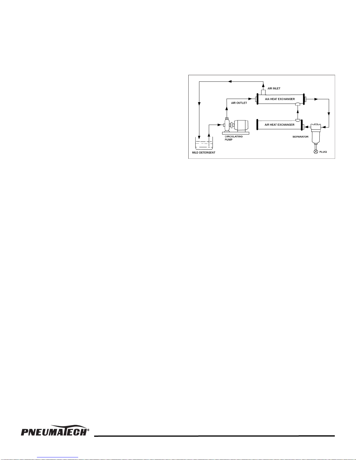
MILD DETERGENT. See Figure 2.
To back-flush, disconnect air dryer, plug the drain line
and fill the air system with the detergent water solution.
Hold it for 4-6 hours. Circulate the detergent from air
outlet to air inlet with a pump. Flush the system with
warm water. If pressure-drop still exists, contact factory.
FIGURE 2 — BACK FLUSH FLOW DIAGRAM
AUTOMATIC DRAINS
The recommended settings for the drain time are
determined by the moisture load. The cycle time should
be adjusted to approximately 3 to 4 minutes. The drain
time should be set so the drain expels all of the liquid
and then a short burst of air.
Periodically check the automatic drains for proper
drainage. If the drains are not functioning, the
condensed moisture will be re-entrained downstream of
the air dryer. Float operated automatic drains need
periodic cleaning with soap and water to remove solids
from the valve seat. If the valve is stuck open, clean with
soap and water and then use compressed air to clean
the valve seat. Electronic solenoid operated drains may
be manually tested periodically for proper operation.
11
Page 13
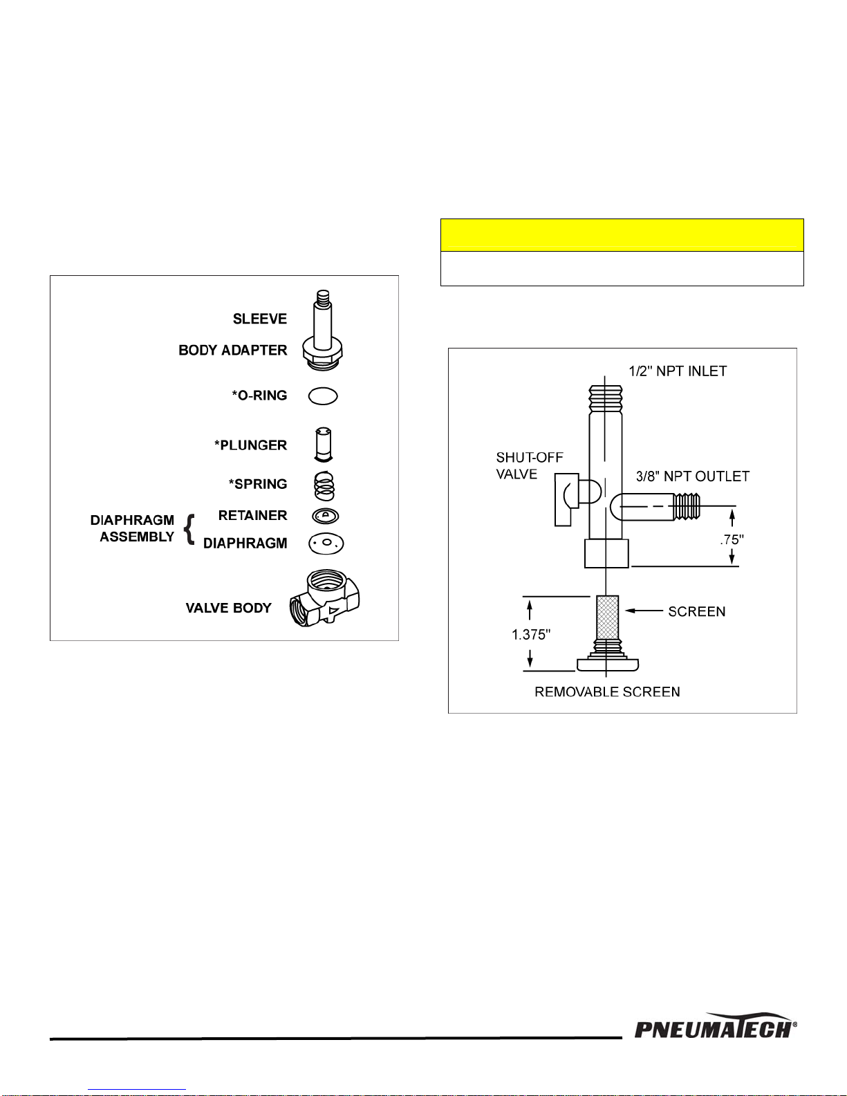
Drain Valve Clean Up Procedure
A. Depressurize the drain valve.
B. Disconnect the power source.
C. Remove the valve from the compressed air system.
D. Remove the solenoid coil.
E. Remove the stainless steel sleeve from valve body.
F. Clean the valve body internals, and all other
components.
G. Replace diaphragm as needed. The valve rebuild kit
is available.
H. Assemble the valve parts.
Connect the solenoid coil.
I.
J. Install the drain valve in the system.
Recommended Operation and
Maintenance for the Particle Strainer
The particle strainer should be cleaned once every week
or as needed.
1. Close the shut-off valve on the particle strainer.
2. Depressurize the drain by pressing the drain PRESS
TO TEST or DRAIN TEST key.
CAUTION
Failure to depressurize may cause bodily injury.
3. Unscrew bottom of the particle strainer and clean
the screen.
FIGURE 3 — DRAIN VALVE
FIGURE 4 — PARTICLE STAINER
12
Page 14
COMPRESSOR HOT GAS BYPASS VALVE
Refrigerant compressors normally do not need any
maintenance. The compressor will unload or adjust for
different load conditions with the refrigeration controls.
Any time power is applied to the compressor, and the
suction pressure is higher than the specified readings,
the compressor is either not pumping or failed
electrically, or tripped “off” at the overload protection. If
the compressor does not automatically reset within a few
minutes, it requires servicing. Service must be
performed by a qualified refrigeration technician.
EXPANSION VALVE
Air dryers equipped with an automatic expansion valve
are factory adjusted for proper cooling. The valve
adjusting stem is secured with a lock nut at the factory to
maintain proper setting. Larger units are equipped with a
thermostatic expansion valve, factory set to maintain a
superheat of 8 to 10°F (-13 to -12°C). These valves do
not need adjustment in normal operation. Generally,
superheat adjustments are needed only at the time of
valve replacement. Expansion valve service must be
performed by a qualified refrigeration technician.
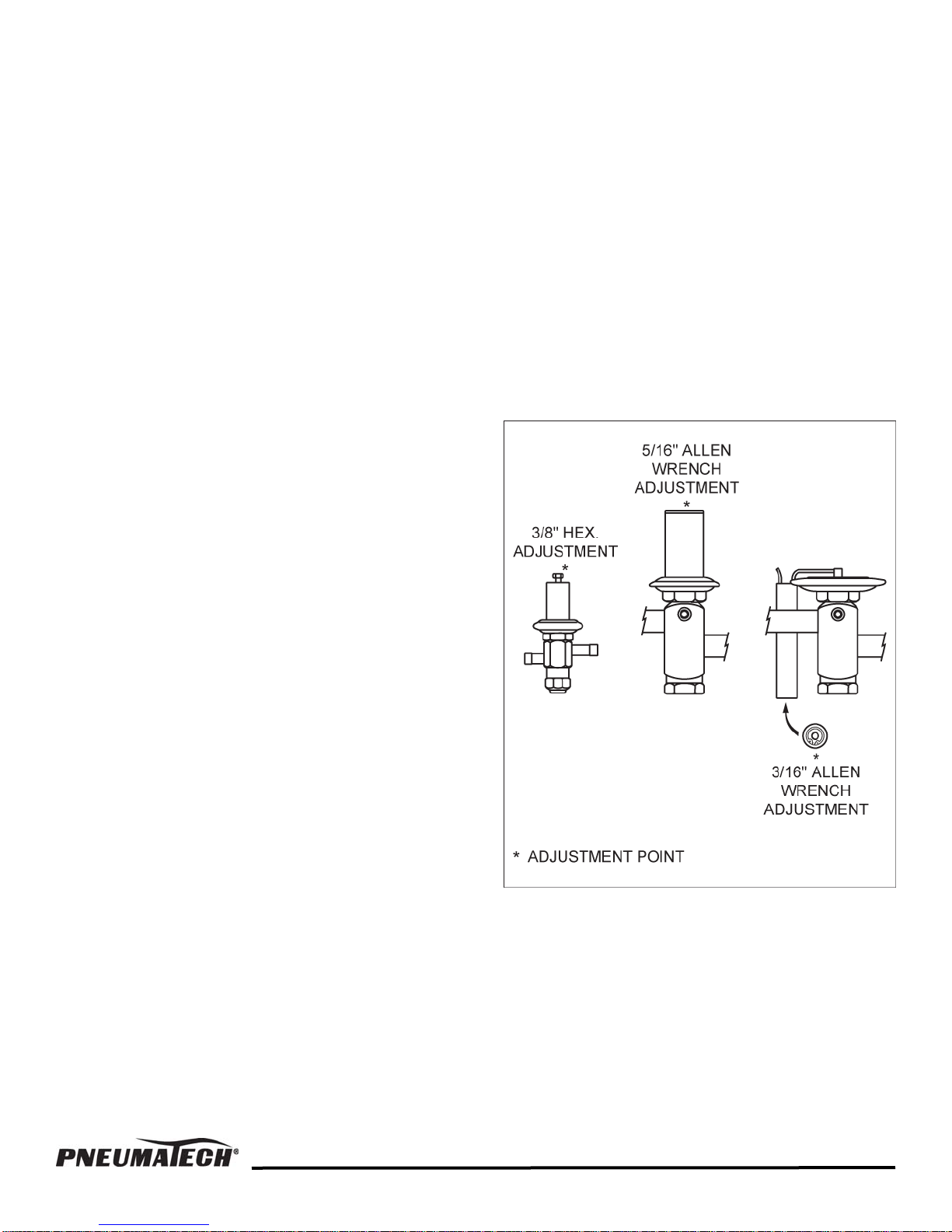
These air dryers come equipped with modulating hot gas
bypass valve
suction pressure in varying load conditions. The dryer
will run from no load to full load conditions without
freeze-up. The operation of this valve is automatic. If the
valve needs adjustment, turn the adjusting stem
clockwise to raise the suction pressure, and
counterclockwise to lower the suction pressure. This
adjustment should be made under a no-load condition
only. When the adjustment is made, turn one quarter of
a turn at a time, and wait 3 to 5 minutes between
adjustments. Once the adjustment is complete, secure
the adjusting stem with the locknut that is provided.
Careful adjustment of this valve is necessary for normal
operation of the air dryer. Hot gas bypass valve
adjustment may be made by maintenance personnel.
See Figure 5.
FIGURE 5 — HOT GAS BYPASS VALVE ADJUSTMENTS
s. This valve maintains the refrigerant
13
Page 15
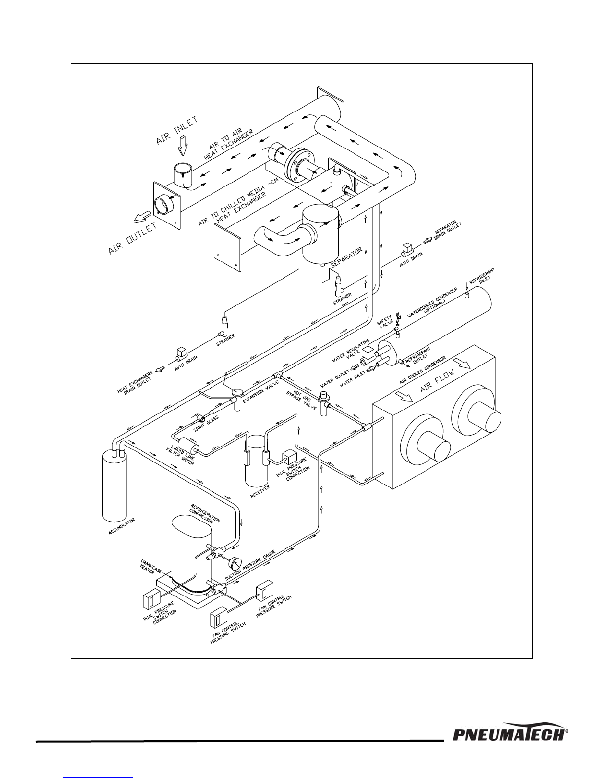
FIGURE 6 — FLOW DIAGRAM AD-750 to 1000
14
Page 16
15
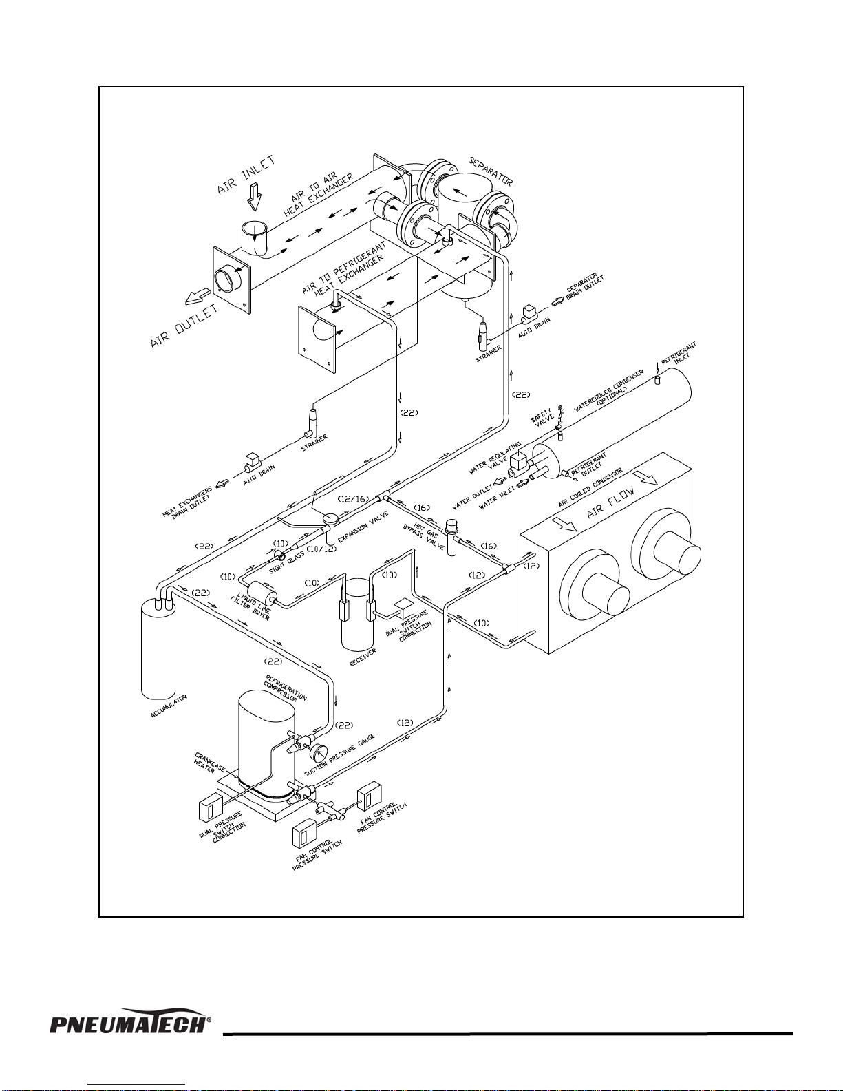
FIGURE 7 — FLOW DIAGRAM AD-1200 to 2000
Page 17
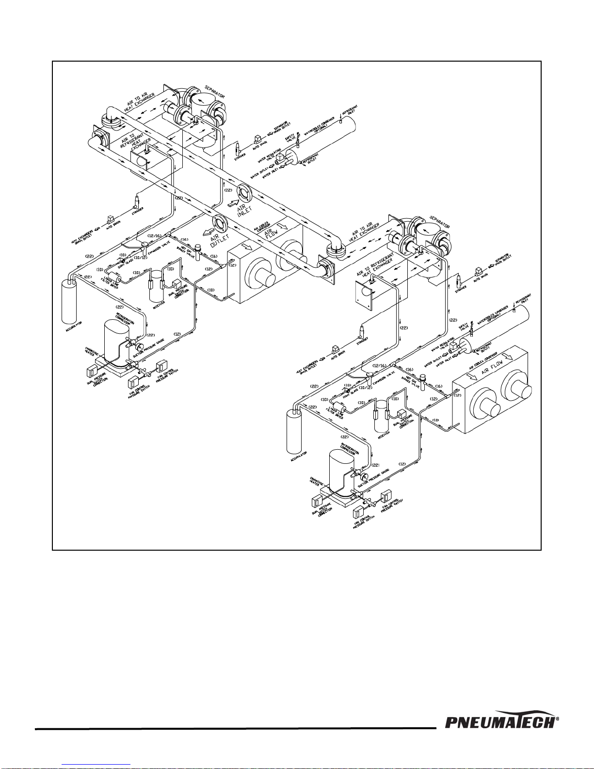
FIGURE 8 — FLOW DIAGRAM AD-2500 to 4000
16
Page 18

REFRIGERATED AIR DRYER SERVICE CHECKLIST
Please get answers to as many questions as you can before writing or calling for service.
1. Customer’s Name ______________________________________________________________________________
Phone no. ________________________________ Fax no. ____________________________________________
2. Model no. ________________________________ Serial no. __________________________________________
Voltage L1 _____________ L2 _______________ L3 ______________ PH _____________ HZ ______________
Amp draw L1 ________________________ L2 _________________________ L3 _________________________
Actual air flow (SCFM) _________________________ HP ____________________________________________
3. Description of problem
_____________________________________________________________________________________________
_____________________________________________________________________________________________
_____________________________________________________________________________________________
_____________________________________________________________________________________________
_____________________________________________________________________________________________
_____________________________________________________________________________________________
_____________________________________________________________________________________________
_____________________________________________________________________________________________
4. Air in temperature (°F) ___________________________________________________________________________
5. Air out temperature (°F) _________________________________________________________________________
6. Air in pressure (PSIG) ___________________________________________________________________________
7. Air out pressure (PSIG) __________________________________________________________________________
8. Refrigerant suction pressure when unit is operating (PSIG) ______________________________________________
9. Refrigerant suction pressure when unit is not operating (PSIG) ___________________________________________
10. Refrigerant discharge pressure when unit is operating (PSIG) ____________________________________________
11. Inspect refrigerant suction line at the outlet of air to refrigerant heat exchanger:
Cold _______________________ Hot _______________________ Temperature (°F) _______________________
12. Inspect refrigerant suction line at inlet of compressor: Temperature (°F) ____________________________________
13. Oil pressure when unit is operating (PSIG) ___________________________________________________________
14. Separator skin temperature (°F) ___________________________________________________________________
15. Location of unit: Indoor ___________________________ Outdoor ________________________________
Clean ___________________________ Dusty __________________________________
16. Ambient temperature (°F) _________________ Air-cooled condenser clean? Yes ___________ No ____________
17. a. Water-cooled condenser: City ____________________________ Tower ________________________________
b. Inlet water temperature (°F) _______________________ Outlet water temperature (°F) ____________________
c. Inlet water pressure (PSIG) ________________________ Outlet water pressure (PSIG) ____________________
18. Inspect auto drain, operation: Stuck open ________________________ Stuck closed ________________________
NOTE: Maintenance Personnel, Copy This Page, Fill In Form and Fax to 262-658-1945
17
Page 19
TROUBLESHOOTING
The following conditions can cause abnormal operation or malfunction of the air dryer
• High inlet air temperatures
• Low inlet air pressures
• High cooling water inlet temperatures
• Untreated cooling water
• Dirty condenser
• Low ambient temperatures
• Malfunctioning automatic drains at aftercooler, or dryer
• Refrigerant overcharge
• Leaky evaporator
• Electrical power supply more than ±10% of the rated
voltage
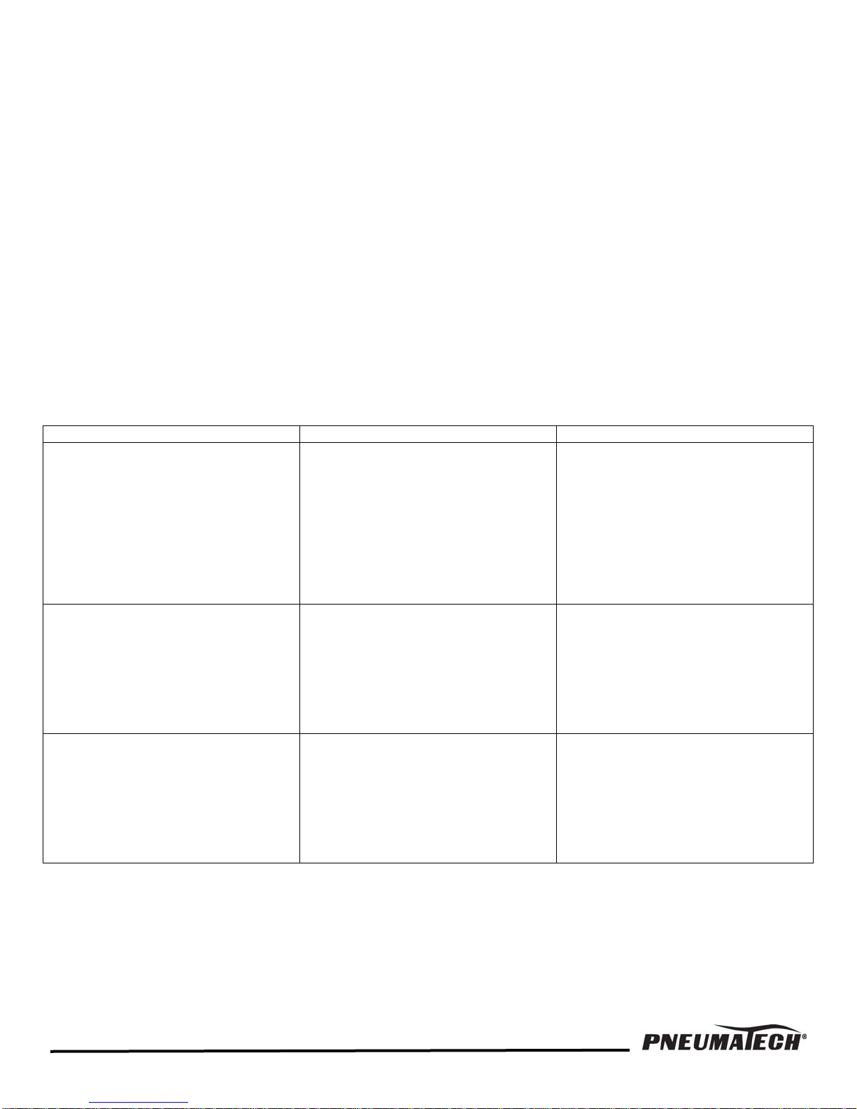
Table 1 — Troubleshooting Guide
Symptoms Cause Remedy
A. Unit does not run. 1. Motor line open.
2. Fuse blown.
3. Tripped overload.
4. Safety controls open.
5. Air switch open. (Dead end
control)
6. Frozen (locked) compressor.
7. Wiring improper or loose.
B. Unit short cycles. 1. Motor compressor overload cutting
out.
2. Shortage of refrigerant.
3. Suction pressure low.
4. Sticking expansion valve.
C. Compressor will not start – hums. 1. Improperly wired.
2. Low line voltage.
3. Starting capacitor defective.
4. Relay or contactor not closing.
5. Start winding open.
6. Single-phasing.
• Contaminated cooling water
• Condenser water pressure below 35 PSIG
• High ambient temperatures
• Compressed air flow greater than rated capacity
• Undersized fuses
• Refrigerant undercharge
• Clogged air compressor air intake filter
If any of these symptoms are noticed, refer to
Troubleshooting Guide.
1. Close disconnect switch, to start.
2. Replace fuse.
3. Turn switch off, wait 15 minutes,
check for overload condition.
4. Repair or replace.
5. Check air pressure. Adjust air
and/or switch. If defective repair or
replace.
6. Repair or replace.
7. Check wiring against diagram.
1. Check for high head pressure,
clogged condenser, high ambient,
or air overload. Check high
pressure cutout, repair or replace.
2. Repair leak and recharge.
3. Check hot gas bypass adjust,
repair or replace.
4. Repair or replace.
1. Check wiring against diagram.
2. Check voltage – correct.
3. Replace.
4. Check for reason – repair or
replace.
5. Check leads, if leads OK replace
motor.
6. Check fuses.
18
Page 20

Table 1 — Troubleshooting Guide, continued
Symptoms Cause Remedy
D. Compressor starts and runs –
short cycles on overload.
E. Relay burned out. 1. Low or high line voltage.
F. Capacitors burn out. 1. Improper capacitor.
G. Head pressure too high. 1. Refrigerant overcharge.
H. Head pressure too low. 1. Refrigerant shortage.
I. Noisy unit. 1. Mountings loose.
J. Frosted liquid line. 1. High side service valve partially
K. Frosted suction line. 1. Expansion valve and/or hot gas
L. Top condenser coils cool when
unit in operation.
1. Low voltage, or phase unbalance.
2. Additional current going through
overload.
3. Overload protectors defective.
4. Run capacitor weak.
5. High discharge pressure.
6. Short in winding.
7. Current relay sticking.
2. Incorrect running capacitor.
3. Short cycling.
4. Wrong relay.
5. Incorrect mounting.
2. High line voltage.
2. Air in system.
3. Dirty condenser.
4. Location too hot.
5. Defective condenser pressure
switch.
6. Defective fan motor.
7. Fan operating in wrong direction.
8. Defective water regulating valve.
2. Compressor suction or discharge
valves inefficient.
3. Defective condenser pressure
switch.
4. Defective water regulating valve.
2. Bent fan blade.
3. Fan motor bearing worn.
4. Refrigerant flooding back.
5. Compressor oil charge low.
closed or restricted.
2. Restricted filter/dryer.
bypass out of adjustment.
1. Refrigerant shortage.
2. Compressor inefficient.
1. Check voltage to be within ±10%
of voltage listed on name plate.
2. Check wiring diagram, check for
added electrical devices
connected thru protector.
3. Check current, replace.
4. Check capacitance, replace.
5. Refer to G 1-8.
6. Check resistance, replace
compressor.
7. Check floor level, tap & release.
1. Check voltage to be within ±10%
of voltage listed on name plate.
2. Replace with proper capacitance.
3. Refer to B and C.
4. Replace with proper relay.
5. Mount in correct, rigid position.
1. Replace with proper capacitor.
2. Lower voltage to not more than
10% above rating.
1. Purge or vacuum and recharge.
2. Check for reason, repair.
3. Blow clean with compressed air.
4. Cool ambient, relocate unit, add
ventilation.
5. Repair or replace.
6. Replace.
7. Switch two wires at disconnect.
8. Adjust, repair or replace.
1. Repair leak and recharge.
2. Repair or replace.
3. Repair or replace.
4. Adjust, repair or replace.
1. Tighten mounting, etc.
2. Straighten or replace blade.
3. Replace.
4. Check expansion valve, adjust,
repair or replace. Check
crankcase heater.
5. Check oil level.
1. Open valve or remove restriction.
2. Replace.
1. Adjust the hot gas bypass valve to
bring the suction pressure into the
proper range.
1. Repair leak and recharge.
2. Repair or replace.
19
Page 21
Table 1 — Troubleshooting Guide, continued
Symptoms Cause Remedy
M. Unit runs but air temperature is
high.
NOTE: Outlet air temperature gauge
may read higher than actual
temperatures at low air flow
conditions.
N. Unit runs but low air pressure. 1. System pressure low.
O. Unit runs, but air flow erratic or
zero.
P. Evaporator freeze-up. 1. Hot gas bypass valve out of
Q. Condenser fan blows outward. 1. Improper wiring at disconnect (3
1. Refrigerant leak.
2. Evaporator controls set too high.
3. Filter/dryer clogged.
4. Refrigerant shortage.
5. Dirty condenser.
6. Air in system.
7. Compressor inefficient.
8. Evaporator control(s) stuck.
9. Defective insulation.
10. Air overload.
11. Unit too small.
12. High ambient.
13. Entering air temperature too high.
2. Precooler and/or evaporator
clogged.
3. Incorrect piping.
4. Air overload.
5. Unit too small.
6. Excess water in unit.
7. Evaporator freeze-up.
8. Clogged air compressor intake
filter.
9. Dirty air system.
1. Freeze-up.
2. Precooler and/or evaporator
clogged.
3. Restriction in piping upstream from
unit.
adjustment.
phase only)
1. Locate with leak detector. Repair
or replace defective part.
2. Refer to K – above.
3. Replace.
4. Repair leak and recharge.
5. Clean condenser.
6. Check reason, repair, vacuum,
recharge.
7. Repair or replace.
8. Repair as required, adjust.
9. Repair.
10. Reduce load.
11. Add unit or replace.
12. Reduce or change location.
13. Lower entering air temperature.
1. Increase pressure.
2. Back-flush using mild detergent,
Figure 2 on Page 11.
3. Increase line size and/or correct
piping as required.
4. Reduce overload.
5. Add another unit or replace with
larger unit.
6. Check drain, repair or replace if
needed.
7. Adjust hot gas bypass valve.
8. Clean or replace air intake filter.
9. Back-flush as described in Figure
2 on Page 11.
1. Check suction temperature at
evaporator outlet or turn off unit
and allow it to thaw to determine if
this is problem. Adjust controls at
no-load if freezing is occurring.
2. Refer to N-2 above.
3. Correct as required.
1. Adjust suction pressure. Adjust
hot gas bypass valve.
1. Reverse two wires.
20
Page 22

21
Page 23

22
Page 24

Pneumatech
th
4909 70
Avenue
Kenosha, WI 53144
Phone: 262-658-4300
Fax: 262-658-1945
www.pneumatech.com
 Loading...