

Page 1

PNEUMATECH
750, AD 1000, AD 1250
AD
Instruction book
Page 2

Page 3

PNEUMATECH
AD 750, AD 1000, AD 1250
Instruction book
2017 - 06
Original instructions
Copyright notice
Any unauthorized use or copying of the contents or any part thereof is prohibited.
his applies in particular to trademarks, model denominations, part numbers and drawings.
T
This instruction book is valid for CE as well as non-CE labelled machines. It meets the
requirements for instructions specified by the applicable European directives as identified in the
Declaration of Conformity.
No. 9828 0931 61
ww.pneumatech.com
w
Page 4

Instruction book
Table of contents
1 Safety precautions ..........................................................................................................6
1.1 SAFETY ICONS ............................................................................................................................... 6
1.2 GENERAL SAFETY PRECAUTIONS .................................................................................................... 6
1.3 SAFETY PRECAUTIONS DURING INSTALLATION ................................................................................. 7
1.4 SAFETY PRECAUTIONS DURING OPERATION ..................................................................................... 8
.5 SAFETY PRECAUTIONS DURING MAINTENANCE OR REPAIR ................................................................ 9
1
2 General description ....................................................................................................... 10
2.1 INTRODUCTION ............................................................................................................................ 10
2.2 AIR SYSTEM ................................................................................................................................ 13
2.3 REFRIGERATION SYSTEM ............................................................................................................. 14
2.4 AUTOMATIC REGULATION SYSTEM ................................................................................................. 15
2.5 ELECTRICAL SYSTEM ................................................................................................................... 16
3 Installation ..................................................................................................................... 17
3.1 DIMENSION DRAWINGS ................................................................................................................. 17
.2 INSTALLATION PROPOSAL ............................................................................................................. 18
3
3.3 ELECTRIC CABLE SIZE AND SETTING OF MOTOR CIRCUIT BREAKER .................................................. 22
3.4 PICTOGRAPHS ............................................................................................................................. 23
4 Operating instructions .................................................................................................. 25
4.1 CONTROL PANEL ......................................................................................................................... 25
4.2 STARTING ................................................................................................................................... 31
4.3 DURING OPERATION ..................................................................................................................... 32
4.4 STOPPING ................................................................................................................................... 32
4.5 PRESSURE DISCHARGE PROCEDURE ............................................................................................. 34
4.6 DISMANTLING .............................................................................................................................. 34
5 Maintenance ................................................................................................................... 35
4 9828 0931 61
Page 5

Instruction book
5.1 MAINTENANCE INSTRUCTIONS ...................................................................................................... 35
5.2 DISPOSAL OF USED MATERIAL....................................................................................................... 36
6 Settings .......................................................................................................................... 37
6.1 DEVICE SETTINGS ........................................................................................................................ 37
7 Problem solving ............................................................................................................ 38
7.1 PROBLEM SOLVING ...................................................................................................................... 38
8 Technical data ............................................................................................................... 41
.1 REFERENCE CONDITIONS AND LIMITATIONS ................................................................................... 41
8
8.2 AIR DRYER DATA .......................................................................................................................... 42
9828 0931 61 5
Page 6
1 Safety precautions
1.1 Safety icons
Explanation
Danger to life
Warning
Important note
Instruction book
1.2 General safety precautions
1. The operator must employ safe working practices and observe all related work safety requirements and
regulations.
2. If any of the following statements does not comply with the applicable legislation, the stricter of the two
shall apply.
3. Installation, operation, maintenance and repair work must only be performed by authorized, trained,
specialized personnel. The personnel should apply safe working practices by use of personal protection
equipment, appropriate tools and defined procedures.
4. The machine is not considered capable of producing air of breathing quality. For air of breathing quality, the
compressed air must be adequately purified according to the applicable legislation and standards.
5. Before any maintenance, repair work, adjustment or any other non-routine checks:
• Stop the machine.
• Press the emergency stop button.
• Switch off the voltage.
• Depressurize the machine.
• Lock Out - Tag Out (LOTO):
Open the power isolating switch and lock it with a personal lock.
Tag the power isolating switch with the name of the service technician.
• On units powered by a frequency converter, wait 10 minutes before starting any electrical
repair.
• Never rely on indicator lamps or electrical door locks before maintenance work, always
disconnect and check with measuring device.
If the machine is equipped with an automatic restart after voltage failure function
and if this function is active, be aware that the machine will restart automatically
when the power is restored if it was running when the power was interrupted!
6. Never play with compressed air. Do not apply the air to your skin or direct an air stream at people. Never
use the air to clean dirt from your clothes. When using the air to clean equipment, do so with extreme
caution and wear eye protection.
7. The owner is responsible for maintaining the unit in safe operating condition. Parts and accessories shall
be replaced if unsuitable for safe operation.
8. It is not allowed to walk or stand on the unit or on its components.
6 9828 0931 61
Page 7

Instruction book
All responsibility for any damage or injury resulting from neglecting these precautions,
care required for installation, operation,
maintenance and repair, even if not expressly stated, will be disclaimed by the
These precautions apply to machinery processing or consuming air or inert gas.
Processing of any other gas requires additional safety precautions typical to the
cover several machine types and equipment; hence
9. If compressed air is used in the food industry and more specifically for direct food contact, Pneumatech
recommends, for optimal safety, the use of certified Class 0 compressors in combination with appropriate
filtration depending on the application. Please contact your Pneumatech Customer Center for advice on
specific filtration.
1.3 Safety precautions during installation
or non observance of the normal caution and
manufacturer.
Precautions during installation
1. The machine must only be lifted using suitable equipment in accordance with the applicable safety
regulations. Loose or pivoting parts must be securely fastened before lifting. It is strictly forbidden to dwell
or stay in the risk zone under a lifted load. Lifting acceleration and deceleration must be kept within safe
limits. Wear a safety helmet when working in the area of overhead or lifting equipment.
2. The unit is designed for indoor use.
3. Place the machine where the ambient air is as cool and clean as possible.
4. Any blanking flanges, plugs, caps and desiccant bags must be removed before connecting the pipes.
5. Air hoses must be of correct size and suitable for the working pressure. Never use frayed, damaged or
worn hoses. Distribution pipes and connections must be of the correct size and suitable for the working
pressure.
6. Ensure that the discharge pipe from the dryer to the air net is free to expand under heat and that it is not
in contact with or close to flammable materials.
7. No external force may be exerted on the air outlet valve; the connected pipe must be free of strain.
8. If remote control is installed, the machine must bear a clear sign stating: DANGER: This machine is
remotely controlled and may start without warning.
The operator has to make sure that the machine is stopped and that the isolating switch is open and
locked before any maintenance or repair. As a further safeguard, persons switching on remotely
controlled machines shall take adequate precautions to ensure that there is no one checking or working
on the machine. To this end, a suitable notice shall be affixed to the start equipment.
9. The electrical connections must correspond to the applicable codes. The machines must be earthed and
protected against short circuits by fuses in all phases. A lockable power isolating switch must be installed
near the dryer.
10. On machines with automatic start-stop system or if the automatic restart function after voltage failure is
activated, a sign stating "This machine may start without warning" must be affixed near the instrument
panel.
11. Never remove or tamper with the safety devices, guards or insulation fitted on the machine. Every
pressure vessel or auxiliary installed outside the machine to contain air above atmospheric pressure must
be protected by a pressure-relieving device or devices as required.
12. Pipework or other parts with a temperature in excess of 80°C (176°F) and which may be accidentally
touched by personnel in normal operation must be guarded or insulated. Other high-temperature
pipework must be clearly marked.
13. If the ground is not level or can be subject to variable inclination, consult the manufacturer.
Also consult following safety precautions: S
Safety precautions during maintenance.
afety precautions during operation and
application which are not included herein.
Some precautions are general and
some statements may not apply to your machine.
9828 0931 61 7
Page 8
All responsibility for any damage or injury resulting from neglecting these precautions,
normal caution and care required for installation, operation,
maintenance and repair, even if not expressly stated, will be disclaimed by the
precautions apply to machinery processing or consuming air or inert gas.
Processing of any other gas requires additional safety precautions typical to the
es and equipment; hence
1.4 Safety precautions during operation
or non observance of the
manufacturer.
Precautions during operation
1. Never touch any piping or components of the machine during operation.
2. Use only the correct type and size of hose end fittings and connections. When blowing through a hose or
air line, ensure that the open end is held securely. A free end will whip and may cause injury. Make sure
that a hose is fully depressurized before disconnecting it.
3. Persons switching on remotely controlled machines shall take adequate precautions to ensure that there
is no one checking or working on the machine. To this end, a suitable notice shall be affixed to the remote
start equipment.
4. Never operate the machine when there is a possibility of taking in flammable or toxic fumes, vapors or
particles.
5. Never operate the machine below or in excess of its limit ratings.
6. Keep all bodywork doors shut during operation. The doors may be opened for short periods only, e.g. to
carry out routine checks. Wear ear protectors when opening a door.
7. People staying in environments or rooms where the sound pressure level reaches or exceeds 80 dB(A)
shall wear ear protectors.
8. Periodically check that:
• All guards are in place and securely fastened
• All hoses and/or pipes inside the machine are in good condition, secure and not rubbing
• There are no leaks
• All fasteners are tight
• All electrical leads are secure and in good order
• Safety valves and other pressure relief devices are not obstructed by dirt or paint
• Air outlet valve and air net, i.e. pipes, couplings, manifolds, valves, hoses, etc. are in good
epair, free of wear or abuse
r
9. If warm cooling air from dryer is used in air heating systems, e.g. to warm up a workroom, take
precautions against air pollution and possible contamination of the breathing air.
10. Do not remove any of, or tamper with, the sound-damping material.
11. Never remove or tamper with the safety devices, guards or insulations fitted on the machine. Every
pressure vessel or auxiliary installed outside the machine to contain air above atmospheric pressure shall
be protected by a pressure relieving device or devices as required.
Also consult following safety precautions: S
Safety precautions during maintenance.
These
Instruction book
afety precautions during installation and
application which are not included herein.
Some precautions are general and cover several machine typ
some statements may not apply to your machine.
8 9828 0931 61
Page 9

Instruction book
All responsibility for any damage or injury resulting from neglecting these precautions,
nd care required for installation, operation,
maintenance and repair, even if not expressly stated, will be disclaimed by the
to machinery processing or consuming air or inert gas.
Processing of any other gas requires additional safety precautions typical to the
hence
1.5 Safety precautions during maintenance or repair
or non observance of the normal caution a
manufacturer.
Precautions during maintenance or repair
1. Always use the correct safety equipment (such as safety glasses, gloves, safety shoes, etc.).
2. Use only the correct tools for maintenance and repair work.
3. Use only genuine spare parts.
4. All maintenance work shall only be undertaken when the machine has cooled down.
5. A warning sign bearing a legend such as "Work in progress; do not start" shall be attached to the starting
equipment.
6. Persons switching on remotely controlled machines shall take adequate precautions to ensure that there
is no one checking or working on the machine. To this end, a suitable notice shall be affixed to the remote
start equipment.
7. Close the dryer air outlet valve before connecting or disconnecting a pipe.
8. Before removing any pressurized component, effectively isolate the machine from all sources of pressure
and relieve the entire system of pressure.
9. Never use flammable solvents or carbon tetrachloride for cleaning parts. Take safety precautions against
toxic vapours of cleaning liquids.
10. Never use damaging contaminants. (e.g. dust, fibres, fine sand) for cleaning parts.
11. Scrupulously observe cleanliness during maintenance and repair. Keep dirt away by covering the parts
and exposed openings with a clean cloth, paper or tape.
12. Never weld on, or in any way modify, pressure vessels.
13. Whenever there is an indication or any suspicion that an internal part of a machine is overheated, the
machine shall be stopped but no inspection covers shall be opened before sufficient cooling time has
elapsed; this to avoid the risk of spontaneous ignition of the oil vapour when air is admitted.
14. Never use a light source with open flame for inspecting the interior of a machine, pressure vessel, etc.
15. Make sure that no tools, loose parts or rags are left in or on the machine.
16. All regulating and safety devices shall be maintained with due care to ensure that they function properly.
They may not be put out of action.
17. Before clearing the machine for use after maintenance or overhaul, check that operating pressures,
temperatures and time settings are correct. Check that all control and shut-down devices are fitted and
that they function correctly.
18. Protect the motor, air filter, electrical and regulating components, etc. to prevent moisture from entering
them, e.g. when steam cleaning.
19. Make sure that all sound-damping material and vibration dampers, e.g. damping material on the bodywork,
is in good condition. If damaged, replace it by genuine material from the manufacturer to prevent the
sound pressure level from increasing.
20. Never use caustic solvents which can damage materials of the air net, e.g. polycarbonate bowls.
21. The following safety precautions are stressed when handling refrigerant:
• Never inhale refrigerant vapours. Check that the working area is adequately ventilated; if
equired, use breathing protection.
r
• Always wear special gloves. In case of refrigerant contact with the skin, rinse the skin with
water. If liquid refrigerant contacts the skin through clothing, never tear off or remove the latter;
flush abundantly with fresh water over the clothing until all refrigerant is flushed away; then
seek medical first aid.
Also consult following safety precautions: Safety precautions during installation and
Safety precautions during operation.
These precautions apply
application which are not included herein.
Some precautions are general and cover several machine types and equipment;
some statements may not apply to your machine.
9828 0931 61 9
Page 10
2 General description
2.1 Introduction
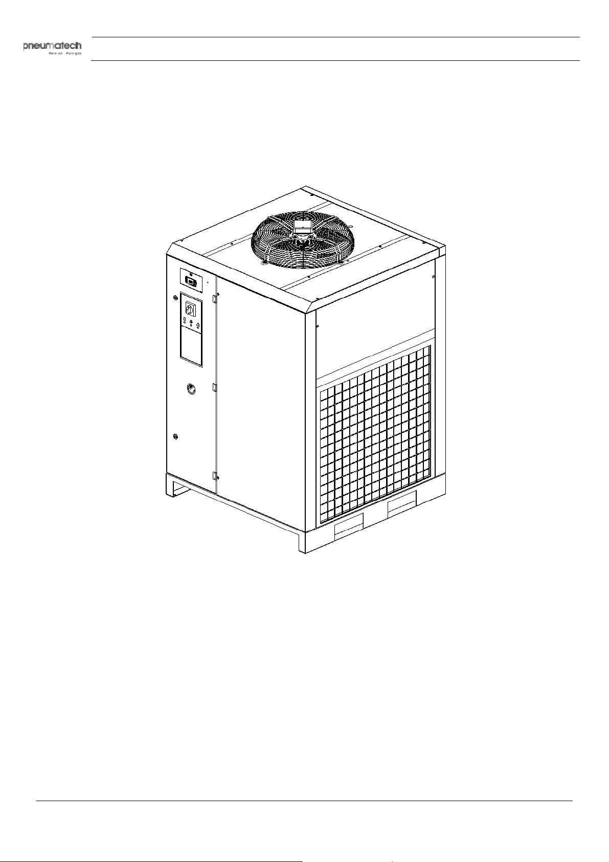
General view
Instruction book
AD 750 up to AD 1250
ntroduction
I
The AD air dryers remove moisture from compressed air by cooling the air near to the freezing point.
This causes water to condense. The condensate is automatically drained. The air is warmed up before
leaving the dryer.
10 9828 0931 61
Page 11
Instruction book
Safety devices
Safety devices
Reference Name
1 Fan protection grid
2 Grounding
3 Safety pressure switch
9828 0931 61 11
Page 12
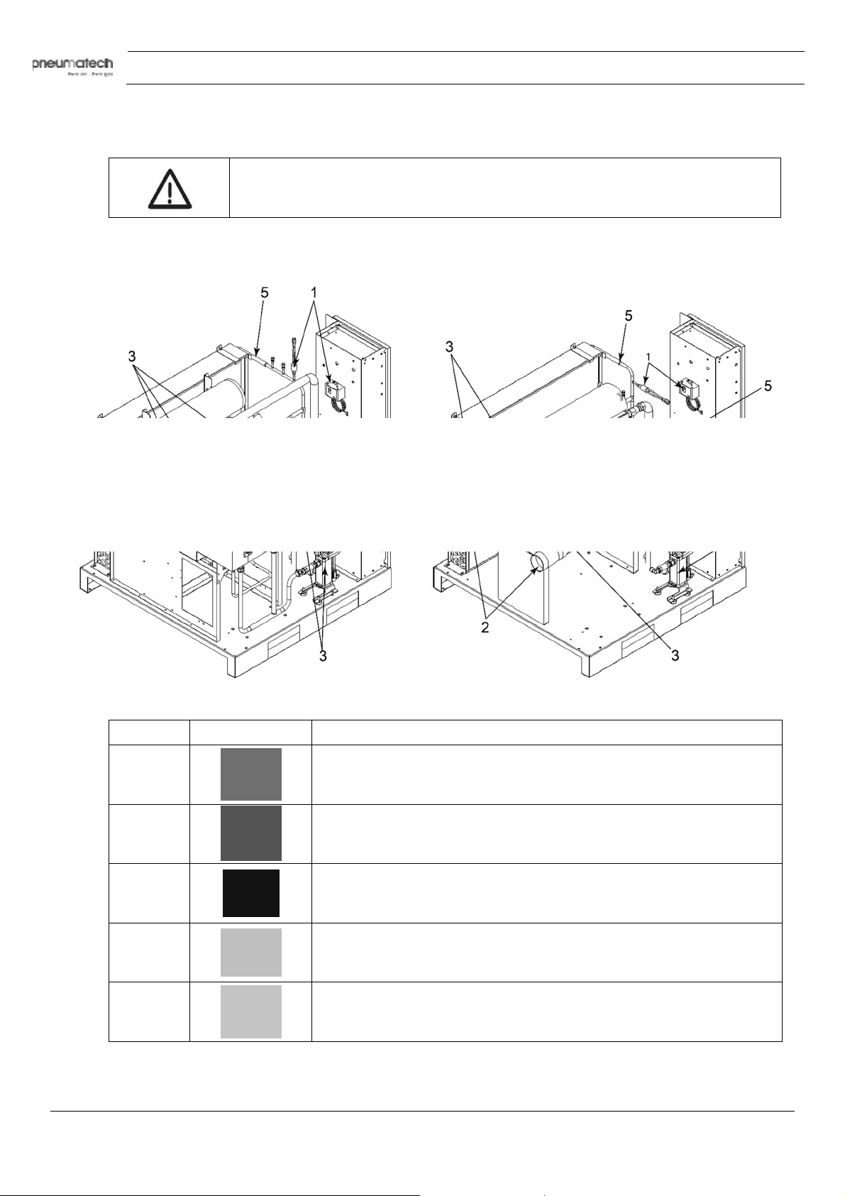
Danger Zones
Refer to images added on the next page for the location of danger zone.
Instruction book
Risks present on the whole machine.
Reference D
1
2
3
4
5
anger signal Description of danger signal
Danger Zones
Dangerous electric voltage
Air not fit for breathing
High pressure
Fan rotating (not shown in image)
Hot parts
12 9828 0931 61
Page 13
Instruction book
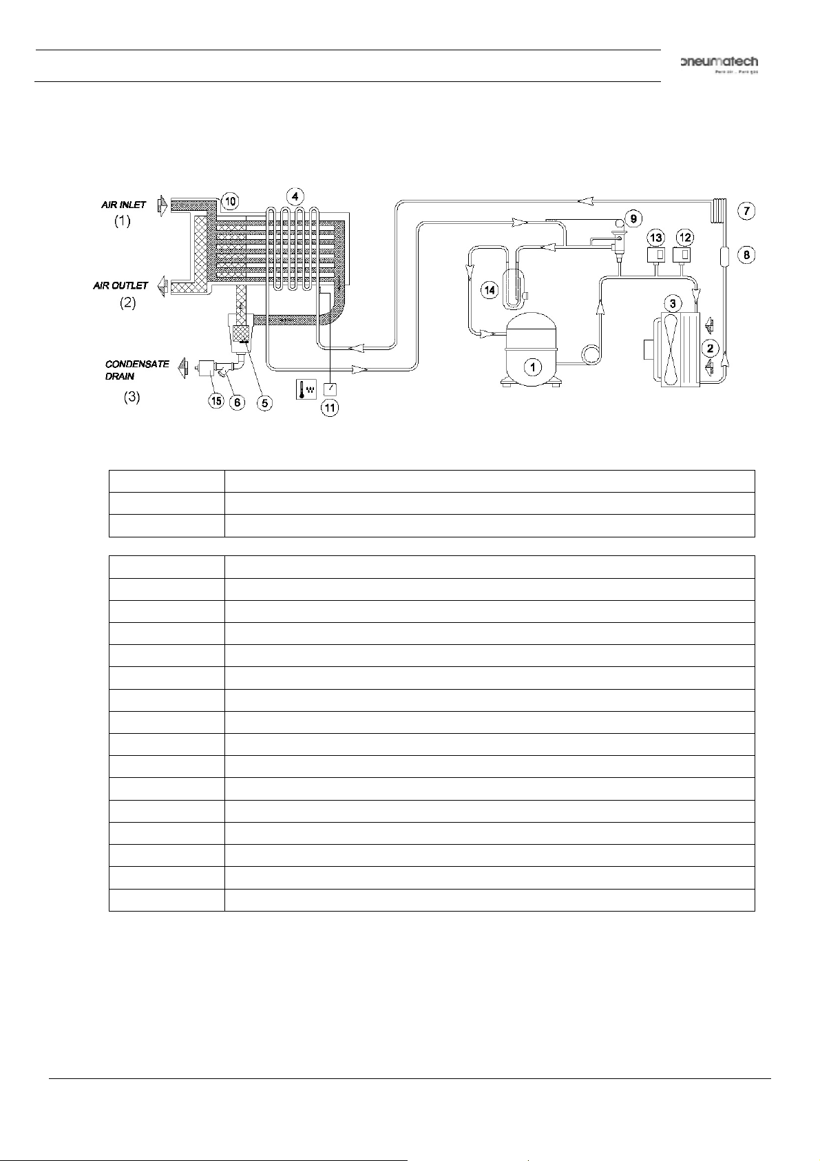
2.2 Air system
Air flow diagram
Text on figure:
(1) Air inlet
(2) Air outlet
(3) Condensate drain
Reference Name
1 Refrigerant compressor
2 Condenser
3 Motor and fan
4 Evaporator
5 Condensate separator
6 Impurity trap
7 Expansion capillary tube
8 Refrigerant filter
9 Hot gas by-pass valve
10 Air/air heat exchanger
11 Digital controller
12 Fan control switch
13 High pressure shut-down switch
14 Liquid separator
15 Automatic condensate drain
Description
Compressed air enters heat exchanger (10) and is pre-cooled by the outgoing, cold, dried air. Water in
the incoming compressed air starts to condense. The air then flows through heat exchanger/evaporator
(4) where the refrigerant evaporates causing the air to be cooled further to close to the evaporating
temperature of the refrigerant. This results in further condensation. The cold air then flows through
separator (5) where all the condensate is separated from the air. The condensate is automatically
drained.
9828 0931 61 13
Page 14
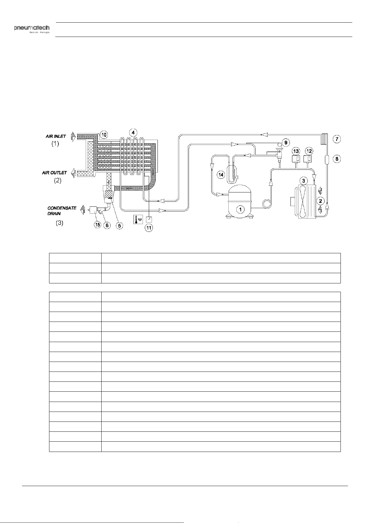
The cold, dried air flows through heat exchanger (10) where it is warmed up by the incoming air to
approx. 10˚C (18˚F) below the incoming air temperature.
Condensation in the air net cannot occur unless the air is cooled below the pressure dewpoint indicated
by the digital controller (11).
2.3 Refrigeration system
Refrigerant flow diagram
Instruction book
ext on figure:
T
(1) Air inlet
(2) Air outlet
(3) Condensate drain
Reference N
1 Refrigerant compressor
2 Condenser
3 Motor and fan
4 Evaporator
5 Condensate separator
6 Impurity trap
7 Expansion capillary tube
8 Refrigerant filter
9 Hot gas by-pass valve
10 Air/air heat exchanger
11 Digital controller
12 Fan control switch
13 High pressure shut-down switch
14 Liquid separator
15 Automatic condensate drain
ame
14 9828 0931 61
Page 15
Instruction book
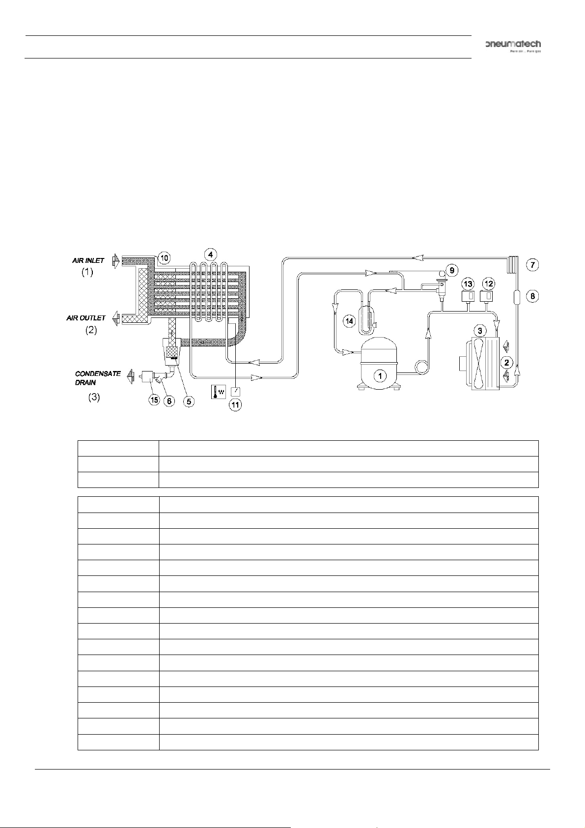
Description
Compressor (1) delivers hot, high-pressure refrigerant gas which flows through condenser (2) where
most of the refrigerant condenses.
The liquid flows through liquid refrigerant dryer/filter (8) to capillary tube (7). The refrigerant leaves the
capillary tube at evaporating pressure.
The refrigerant enters evaporator (4) where it withdraws heat from the compressed air by further
evaporation at constant pressure. The heated refrigerant leaves the evaporator and is sucked in by the
compressor (1).
2.4 Automatic regulation system
Air flow diagram
ext on figure:
T
(1) Air inlet
(2) Air outlet
(3) Condensate drain
Reference Name
1 Refrigerant compressor
2 Condenser
3 Motor and fan
4 Evaporator
5 Condensate separator
6 Impurity trap
7 Expansion capillary tube
8 Refrigerant filter
9 Hot gas by-pass valve
10 Air/air heat exchanger
11 Digital controller
12 Fan control switch
13 High pressure shut-down switch
14 Liquid separator
15 Automatic condensate drain
9828 0931 61 15
Page 16

Description
The condenser pressure must be kept constant to obtain stable operation. Fan control switch (12)
therefore stops and starts the cooling fan (3).
If, under partial or no load, the evaporator pressure drops below a certain level, the hot gas by- pass
valve (9) opens and hot, high-pressure gas is fed to the evaporator circuit to prevent the evaporator
pressure from dropping any further.
2.5 Electrical system
Description
e fan control switch starts the fan motor as soon as the condenser pressure reaches the upper set
Th
point of the switch and will stop the fan motor when the condenser pressure decreases to its lower set
point.
The high pressure shut-down switch stops the compressor motor when the pressure in the refrigerant
circuit reaches the upper setpoint of the switch.
The low pressure shut-down switch stops the compressor motor when the pressure in the refrigerant
circuit drops below the setpoint of the switch.
Instruction book
16 9828 0931 61
Page 17
Instruction book
3 Installation
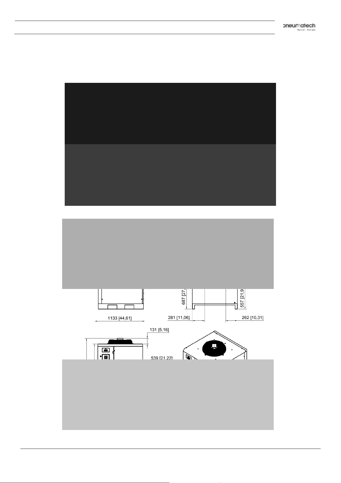
3.1 Dimension drawings
AD 1000 - 1250 connection details
AD 750 connection details
Dimension drawing
9828 0931 61 17
Page 18
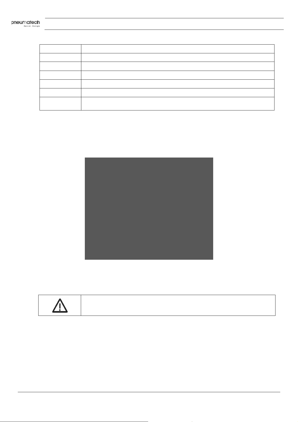
Reference Name
o not cut pieces in the
(1) Electric cable outlet
(2) Condensate drain outlet
(3) Air inlet
(4) Air outlet
(5) NPT adaptors (2X) (UL version only)
(6)
Unit measurement in mm
[x] = [inch]
3.2 Installation proposal
Transport and handling
The machine must be transported as shown in the following figure.
Instruction book
For machine weight, see the section “Air dryer data”.
packing
Un
Cutting the metal strapping is a dangerous operation. D
environment.
After removing the packing, ensure that no damage has occurred to the machine during transportation.
If you are in doubt, do not use the machine. Call your distributor’s service department or dealer.
The packing material (plastic bags, polystyrene foam, nails, screws, wood, metal strapping, and so on.)
must not be left within the reach of children or left in the environment, as they are a potential source of
danger and pollution. Dispose of these materials in the approved collection centers.
18 9828 0931 61
Page 19
Instruction book
Ensure that the operator can see the whole machine from the control panel and check
Moving
Compressor room example
To move the dryer use a forklift truck. Do not use metal cables for lifting.
Move the dryer gently.
the presence of any unauthorized persons in the vicinity of the machine.
9828 0931 61 19
Page 20
Instruction book
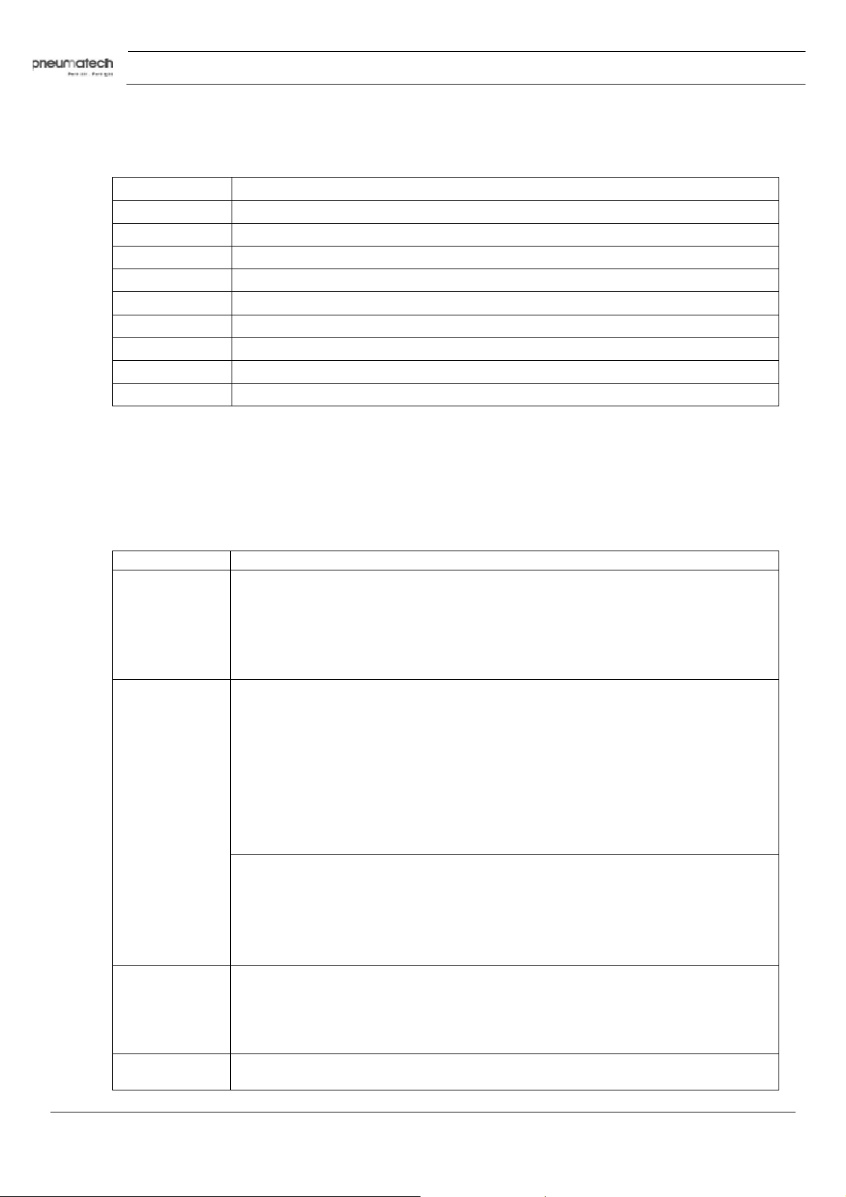
Text on figure:
Reference Name
(1) Compressor
(2) Air receiver
(3) To the air piping
(4) Dryer
(5) Ventilation proposal
(6) Air flow
(7) Minimum free area to be reserved for the dryer’s installation
(8) Service side
(9) Control panel side
• Air treatment with dryer downstream of the air receiver: this can be used when the
compressor runs constantly and the cooling capacity of the dryer is equal to the air delivery of the
compressor. Under this condition the load of the dryer is constant.
• Air treatment with dryer upstream of the air receiver: this can be used when the air demand
is variable. For short periods the air demand is higher than the air delivery of the compressor;
the air receiver must be large enough to meet the instant air demand.
Reference Description
1 The refrigerant air dryer should be installed on a level floor suitable for taking the
weight of the dryer.
Ensure that there is sufficient space around the machine to allow maintenance.
Keep environmental conditions (temperature and humidity) in the machine room
stable to avoid refrigerant compressor/fan overload and/or reduction of dryer
performance. Similar failures will invalidate the warranty.
2 Ventilation: the inlet grids and ventilation fan should be installed in such way that
any recirculation of cooling air to the dryer is avoided. The maximum air velocity to
the grids has to be limited to 5 m/s. The maximum allowable pressure drop over the
cooling air ducts is 30 Pa. When 30 Pa is exceeded, a ventilation fan is needed at
the outlet of the cooling air ducts.
Ensure appropriate composition of the air within the machine room.
The condensate drain pipes must not dip into the condensate. Do not allow
untreated condensate to enter the draining system.
Ensure canalization system (duct and fan) is designed properly. Incorrectly
designed canalization system will lead to machine warranty being made void.
The operating conditions to be complied with are the following:
• Min. room temperature: +5°C (41°F) (compulsory)
• Max. room temperature: +46°C (114,8°F) (compulsory)
• Min. inlet allowed temperature: +3°C (37,4°F)
• Max. inlet allowed temperature: +60°C (140°F)
• Max. working pressure: 14 bar (203 psi)
3 Power supply cable to be sized and installed by a qualified electrician.
Check that the supply voltage is the same as the value indicated on the machine data
plate.
It is recommended to install an automatic cut-out device (in customer scope)
upstream for the machine against overcurrent, with a differential device.
4
Optionally line filters can be provided. Contact your dealer for more info on the
filtration kind and level desired.
20 9828 0931 61
Page 21
Instruction book
due to failure to comply with these indications cannot be attributed to the
Reference Description
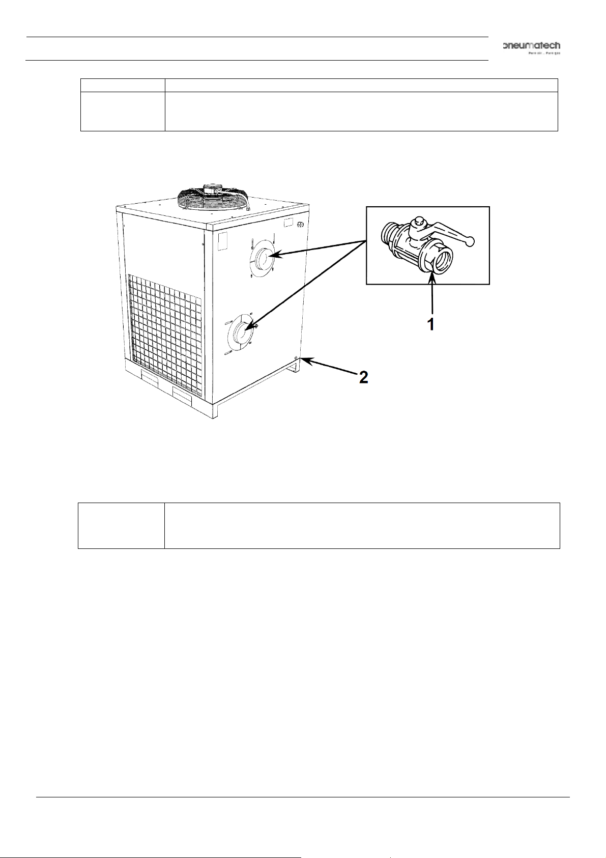
5 It is recommended to install by-pass pipes over each filter and dryer together with
ball valves in order to isolate the filters and/or dryer during service operations,
without disturbing the compressed air delivery.
Connection to the compressed air network
1. Fit a manual ball valve (1) between the machine and the compressed air network to isolate the dryer
during maintenance operations (see above figure).
2. Drainage of automatic condensate (2) are led outside the machine with a flexible pipe. Inspect drain
pipes.
Drainage must comply with the local regulations in force.
All damages
manufacturer and may cause invalidity of the guarantee conditions.
9828 0931 61 21
Page 22
˚C (158 ˚F) at an ambient
˚F) at an ambient
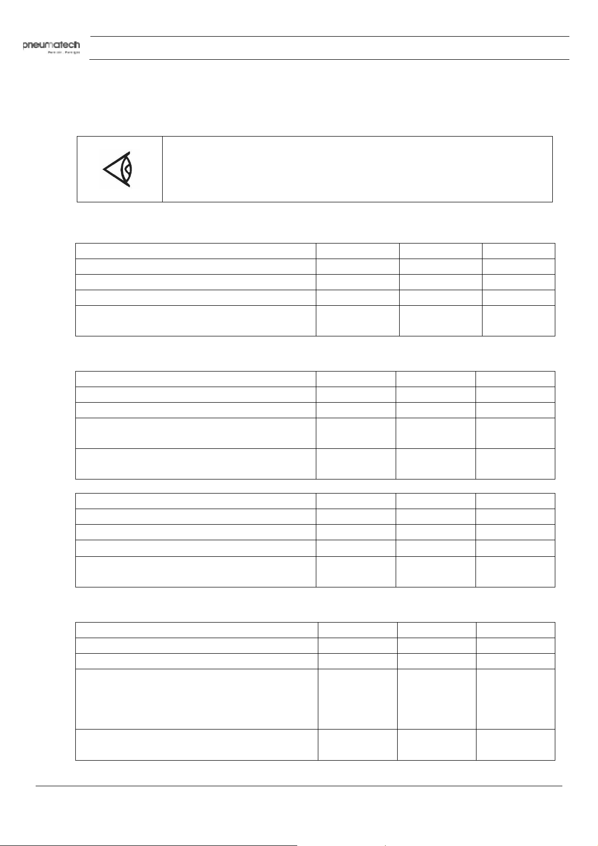
3.3 Electric cable size and setting of motor circuit breaker
Important
Local regulations remain applicable if they are stricter than the values proposed.
For 50 Hz dryers, the cable size is valid for cable PVC 70
temperature of 40 ˚C (104 ˚F).
For 60 Hz dryers, the cable size is valid for cable 90 ˚C (194
temperature of 40 ˚C (104 ˚F).
Electrical data 50 Hz dryers IEC
Voltage [V] 400 400 400
Maximum current [A] (at T
= 46°C / Tin = 60°C) 8.9 10 12.7
amb
Setting motor circuit breaker [A] 13 16 17
AD 750 AD 1000 AD 1250
Instruction book
max cable size mm2 (Maximum cable length
10m/32,8ft)
Electrical data 60 Hz dryers IEC
Voltage [V] 380 380 380
Maximum current [A] (at T
Disconnector switch + Fuses
Type aM 14x51 20 25 32
Maximum cable size mm2 (Maximum cable length
10m/32,8ft)
Voltage [V] 460 460 460
Maximum current [A] (at T
Setting motor circuit breaker [A] 13 16 17
Maximum cable size mm2 (Maximum cable length
10m/32,8ft)
Electrical data 60 Hz dryers UL
Voltage [V] 460 460 460
Maximum current [A] (at T
Disconnector switch (1,25xFLA) + Fuses time delay
CLASS CC 25 30 CLASS RK 20 20 25
6 6 6
AD 750 AD 1000 AD 1250
= 46°C / Tin = 60°C) 11.7 12.3 15.6
amb
10 10 10
AD 750 AD 1000 AD 1250
= 46°C / Tin = 60°C) 9.7 10.2 12.9
amb
6 6 6
AD 750 AD 1000 AD 1250
= 46°C / Tin = 60°C) 9.7 10.2 12.9
amb
Maximum cable size mm2 (Maximum cable length
10m/32,8ft)
22 9828 0931 61
AWG10 AWG10 AWG10
Page 23
Instruction book
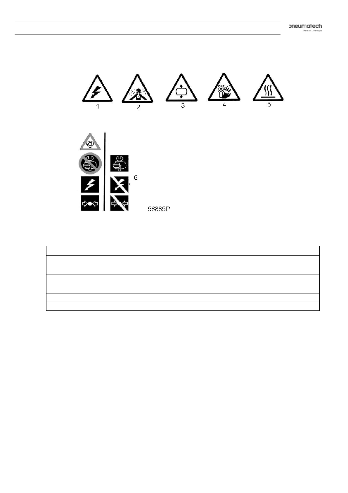
3.4 Pictographs
Pictographs
Pictographs - Danger signals
Reference Na
1 Warning, dangerous electric voltage
2 Warning, air not fit for breathing
3 Warning, high pressure
4 Warning, rotating fan
5 Warning, hot surface
6 Switch off the voltage and depressurize the dryer before maintenance or repair
me
9828 0931 61 23
Page 24
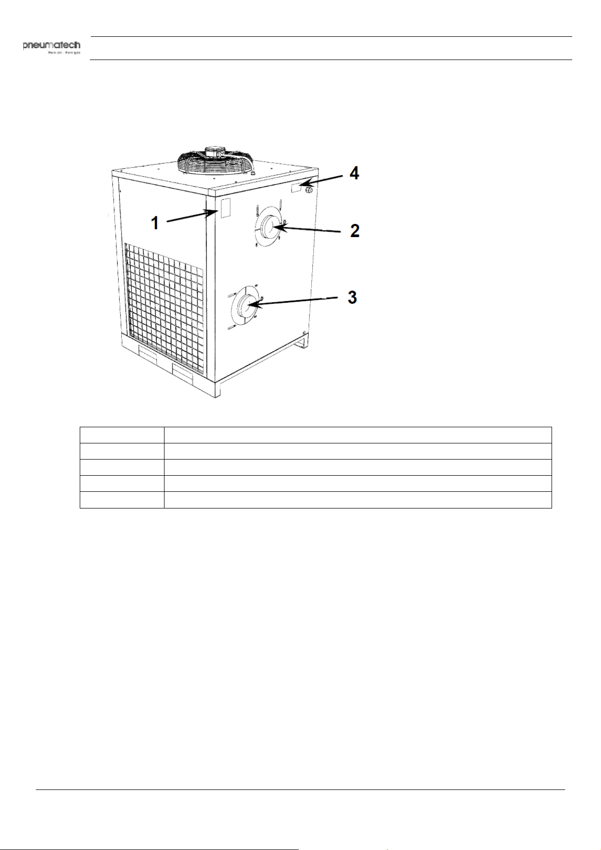
Position of plates
The plates fitted on the compressor unit are part of the machine; they have been applied for safety purposes
and must not be removed or spoiled for any reason.
Instruction book
Reference Name
1 Spare plate Code 1079 9903 48
2 IN
3 OUT
4 Identification plate
Position of the data plates
24 9828 0931 61
Page 25
Instruction book
4 Operating instructions
4.1 Control panel
Description
Reference Na
1 Dryer on/off switch
2 Green indicator for voltage on, dryer running and blocked door
3 Red indicator for alarm for condensate drain
4 Red indicator for alarm for high pressure or fan motor protection
5 Digital controller
me
9828 0931 61 25
Page 26
Digital controller
Identification
Instruction book
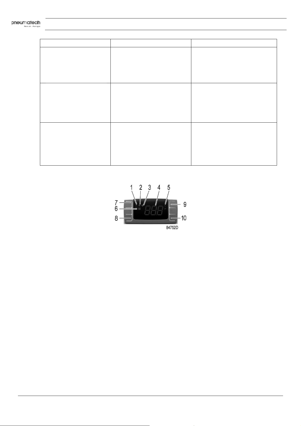
Reference Name
1 Alarm icon
2 Refrigerant compressor icon
3 Fan icon
4 PDP (dewpoint) temperature
5 Unit (°C or °F)
6 Alarm LED
7 Button to snooze or to reset the alarm
8 SET button
9 UP button
10 DOWN buttom
8+9 Back to previous screen
8+10 Menu
Icons
Icon N
Remote alarm function
Front panel of the controller
ame Mode Function
Alarm Off No active alarms
On Probe failure alarm
High temperature or low
temperature alarm
Service alarm
Refrigerant compressor On Dryer on
Flashing + SE Maintenance warning
Flashing + L2 Dewpoint too low
Dryer is stopped
Flashing + H3 Too high discharge
temperature of the
refrigerant compressor
(see further)
Dryer is stopped
Fan Off Fan off
Flashing Not applicable
On Fan on
26 9828 0931 61
Page 27
Instruction book
The controller allows to remotely control a number of alarms. This is managed by means of a free NC
(Normally Closed) contact.
The contact opens in case of an alarm.
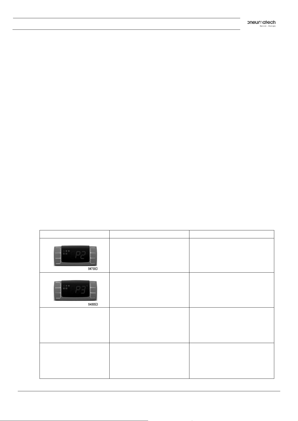
Fault messages
Flashing fault message Description Remedy
ree contact location
F
Dewpoint temperature probe
failure
Refrigerant compressor discharge
temperature probe failure
Pressure dewpoint too high Refer to the fault and remedies
Replace the probe
Replace the probe
section
Pressure dewpoint too low Refer to the fault and remedies
section
9828 0931 61 27
Page 28
Flashing fault message Description Remedy
Resetting the maintenance warning
Instruction book
Refrigerant compressor discharge
temperature too high; refrigerant
compressor stopped.
Internal EPROM error Reset by pressing one of the four
Maintenance required Perform the maintenance and reset
Refer to the fault and remedies
section
buttons.
If the problem persists, replace the
controller
the alarm
Front panel of the controller
To reset the maintenance warning, follow steps 1 to 12:
1. The display is flashing between standard view (dewpoint) and maintenance required (SE) alarm.
2. Push and hold buttons SET (8) and DOWN (10) to enter the menu.
3. Message “SE” appears on display.
4. Push and release the UP button (9).
. Message “rS” appears on display.
5
6. Push and release the SET button (8).
. Message “n” appears on display.
7
28 9828 0931 61
Page 29

Instruction book
8. Push and release the UP button (9).
9. Message “y” appears on display.
10. Push and release SET (8) to reset service alarm.
1. Message “y” blinks for 3 seconds.
1
12. Then “rL” is fixed and “°C” blinks on display for about 10 seconds.
The service alarm is now reset.
Setting the service interval
To set the service interval, follow steps 1 to 9:
1. PDP is showing standard view.
2. Push and hold buttons SET (8) and DOWN (10) to enter the menu.
3. Message “SE” appears on display.
4. Push and release SET (8) to enter the “SE” menu.
. Current service interval is displayed.
5
(“60” or any other value between “0” and “99”)
6. Select desired service interval using the UP and DOWN button.
40=4000h, 55=5500h, 80+8000h,…)
(
7. Push and release SET to confirm the new service interval.
8. The selected value blinks during 3 seconds.
9828 0931 61 29
Page 30

Instruction book
9. Then “rS” is fixed and “°C” blinks on display for about 10 seconds.
The new service interval is now set.
reeze protection function
F
Once the digital controller detects a dewpoint temperature below -2°C during more than 2 minutes, (L2
Alarms), it switches off the refrigerant compressor.
Resetting the dryer after a refrigerant compressor stop
Press button 7 to reset the alarm.
The dryer restarts when both the following conditions are true.
• The dewpoint temperature is higher than -2°C
• 30 second are passed from the refrigerant compressor stop (minimum balancing pressure stop time).
A countdown is available if the reset is made before the minimum stop time.
Silent alarm function
To snooze the alarm, press button 7.
Refrigerant compressor discharge temperature visualization function
To see the discharge refrigerant compressor temperature, follow steps 1 to 5:
1. PDP is showing standard view.
2. Push and hold buttons SET (8) and DOWN (10) to enter the menu.
3. Push and release the UP button (9) until message “S3” appears on display.
4. Push and release the SET button (9) to enter the “S3” parameter.
. Current temperature of discharge refrigerant compressor is displayed.
5
30 9828 0931 61
Page 31
Instruction book
1)
Wait at least 5 minutes to start the dryer again after stopping to allow pressure
To keep the compressed air net free of condensate, start the dryer before starting the
4.2 Starting
Attention
Procedure
The operator must apply all relevant safety precautions.
To ensure optimum operational efficiency, do not use dryer on/off switch (
repeatedly within a short time period.
equalization.
compressor and stop the compressor before stopping the dryer.
Step Ac
1 If installed, close the dryer by-pass valve. See Installation proposal.
2 Switch the on/off switch to On.
3 Open dryer air inlet valve (customer's installation).
4 Approx. 5 minutes later, open dryer air outlet valve (customer's installation).
5 Approx. 10 minutes later, the nominal dewpoint will be reached.
9828 0931 61 31
tion
Page 32
4.3 During operation
To ensure optimum operational efficiency, do not use dryer on/off switch (1)
the dryer again after stopping to allow pressure
To keep the compressed air net free of condensate, start the dryer before starting the
Procedure
Instruction book
gularly check:
Re
• The display of digital controller. The pressure dewpoint will deviate from nominal if the air inlet
conditions or volume flow differ from nominal.
• That condensate is discharged via condensate outlet. The amount depends on the operating
nditions.
co
4.4 Stopping
Attention
repeatedly within a short time period.
Wait at least 5 minutes to start
equalization.
compressor and stop the compressor before stopping the dryer.
32 9828 0931 61
Page 33
Instruction book
Procedure
Step Ac
1 Close the dryer inlet and outlet valve (customer’s installation).
2 Switch off the dryer.
3 If provided, open the dryer by-pass valve.
tion
9828 0931 61 33
Page 34
4.5 Pressure discharge procedure
Instruction book
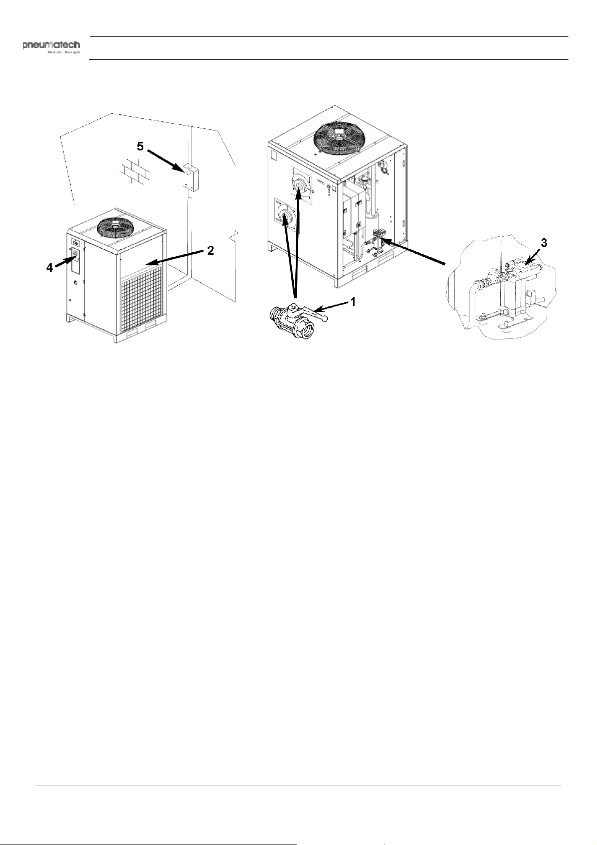
Follow below procedure to depressurize the dryer:
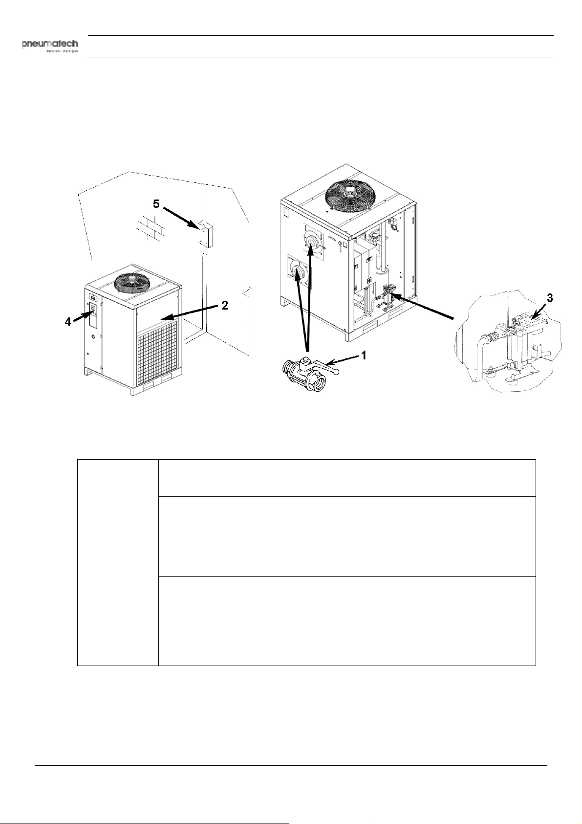
1. Close the ball valve (1).
2. Remove the panel (2).
3. Release the pressure in the dryer by pressing the condensate drain “TEST” pushbutton located on the steam
trap (3).
4. Switch off the machine. Turn the switch to “STOP” (4).
5. Turn on the supply automatic differential switch (5).
6. Close the panel (2).
4.6 Dismantling
Description
Before dismantling, the responsible operating department must de-commission the system and ensure that it
s de-pressurized.
i
Dismantle the product according to local legislation.
34 9828 0931 61
Page 35
Instruction book
starting any maintenance or repair, press the stop button, wait until the dryer
has stopped, press the emergency stop button, switch off the voltage by means of the
on. Apply all relevant safety precautions,
Filters and valves between the compressor, dryer and air consumers may require
5 Maintenance
5.1 Maintenance instructions
Before
isolating switch (customer's installation) and depressurize the dryer.
Safeguard against unintentional switchincluding those mentioned in this book.
other maintenance than stated below. Refer to the appropriate manual for more
information.
Attention
AD type cooling dryers contain refrigerant HFC.
Safety precautions
When handling refrigerant R410A, all applicable safety precautions must be observed. Please be
aware of the following points:
• Contact of refrigerant with the skin will cause freezing. Special gloves must be worn. In case
of contact with the skin, the skin should be rinsed with water. On no account may clothing be
removed.
• Fluid refrigerant will also cause freezing of the eyes; safety glasses must hence be worn.
• Refrigerant R410A is poisonous. Do not inhale refrigerant vapors. Check that the working
area is adequately ventilated.
When removing the side panels of the dryer, be aware that internal elements such as the pipes can
reach a temperature of 120˚C (248˚F). Therefore, wait until the dryer has cooled down before removing
the side panels.
Before starting any maintenance or repair work, switch off the voltage and close the air inlet and outlet
valves.
Local legislation
Local legislation may stipulate that:
• Work on the refrigerant circuit of the cooling dryer or on any equipment which influences its
nction must be undertaken by an authorized control body.
fu
• The installation should be checked once a year by an authorized control body.
General
The following remarks should be kept in mind:
• Keep the dryer clean.
• Inspect and clean the filter of the steam trap daily.
• Brush or blow off the finned surface of the condenser monthly.
9828 0931 61 35
Page 36

5.2 Disposal of used material
Used filters or any other used material (e.g. desiccant, lubricants, cleaning rags, machine parts, etc.)
must be disposed of in an environmentally friendly and safe manner, and in line with the local
recommendations and environmental legislation.
Refer to local regulations for directions on how to dispose of electronic components in an
environmentally friendly manner.
Instruction book
36 9828 0931 61
Page 37

Instruction book
6 Settings
6.1 Device settings
Regulating and safety devices
The regulating and safety devices are factory-adjusted to obtain optimum performance of the dryer. Do
not alter the setting of any of the devices.
9828 0931 61 37
Page 38
7 Problem solving
7.1 Problem solving
Position of air inlet and outlet valves (1) and condensate drain (3)
Instruction book
Attention
se only authorized parts. Any damage or malfunction caused by the use of
U
unauthorized parts is not covered by Warranty or Product Liability.
Apply all relevant Safety precautions during maintenance or repair.
Before carrying out any maintenance or repair work on the dryer:
• Close air inlet and outlet valve of the dryer.
• Press the test button on the electronic condensate drain.
• Move dryer on/off switch to position 0.
• Switch off the voltage. See section Stopping.
• Open the isolating switch to prevent an accidental start.
The air inlet and outlet valve can be locked during maintenance or repair work
as follows:
• Close the valve.
• Using a wrench, remove the screw fixing the handle.
• Lift the handle and turn it until the slot of the handle fits over the blocking edge on
• Fit the screw.
the valve body.
38 9828 0931 61
Page 39
Instruction book
switch
Reset the overload motor protection
order
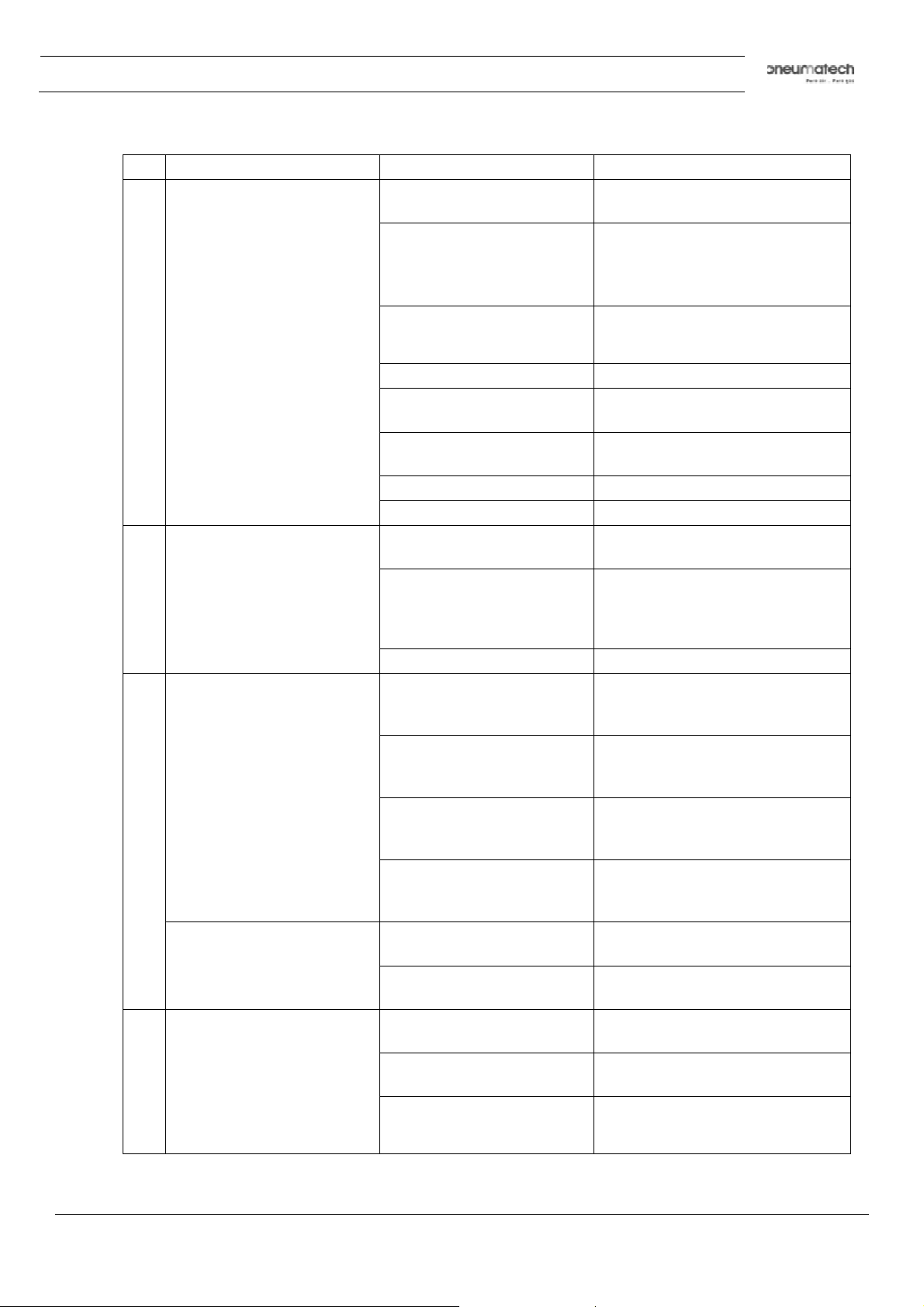
Faults and remedies
Condition Fault Remedy
1 Pressure dewpoint too high Air inlet temperature too high Check and correct; if
2 Condenser pressure too
high or too low
3 Compressor stops or does
not start and PDP is ON
necessary, install a pre-cooler
Ambient temperature too high Check and correct; if
necessary, draw cooling air via
a duct from a cooler place or
relocate the dryer
Air inlet pressure too low Increase inlet pressure
Adjust the pressure
Dryer capacity exceeded Reduce air flow
Shortage of refrigerant Have circuit checked for leaks
and recharged
Refrigerant compressor
does not run
Evaporator pressure too high See 5
Condenser pressure too high See 2
Fan or fan motor out of order Check fan/fan motor
Ambient temperature too high Check and correct; if
Condenser externally clogged Clean condenser
Thermal protection of
refrigerant compressor
motor tripped
Overload fan motor
protection tripped
See 3
necessary, draw cooling air via
a duct from a cooler room or
relocate the dryer
Wait for reset of thermostatic
protection
Compressor does not start
and PDP is OFF
4 The condensate drain
remains inoperative
Phase sequence relay
indicate wrong rotation
High pressure switch
tripped
Fuses of transformer tripped Change fuses
Circuit breaker (in customer
scope) tripped
Drain system clogged Have system inspected
Filter upstream of the
solenoid valve clogged
Timer or solenoid
exhaust valve out of
Change sequence of two phases
Reset the high pressure switch
Check the electrical causes
Check filter
Check timer and solenoid valve
9828 0931 61 39
Page 40

Condition Fault Remedy
5 Evaporator pressure is
too high or too low at
unload
Hot gas by-pass valve
incorrectly set or out of
order
Instruction book
Have hot gas by-pass valve
adjusted
Condenser pressure too
high or too low
Shortage of refrigerant Have circuit checked for leaks
See 2
and recharged
40 9828 0931 61
Page 41
Instruction book
8 Technical data
8.1 Reference conditions and limitations
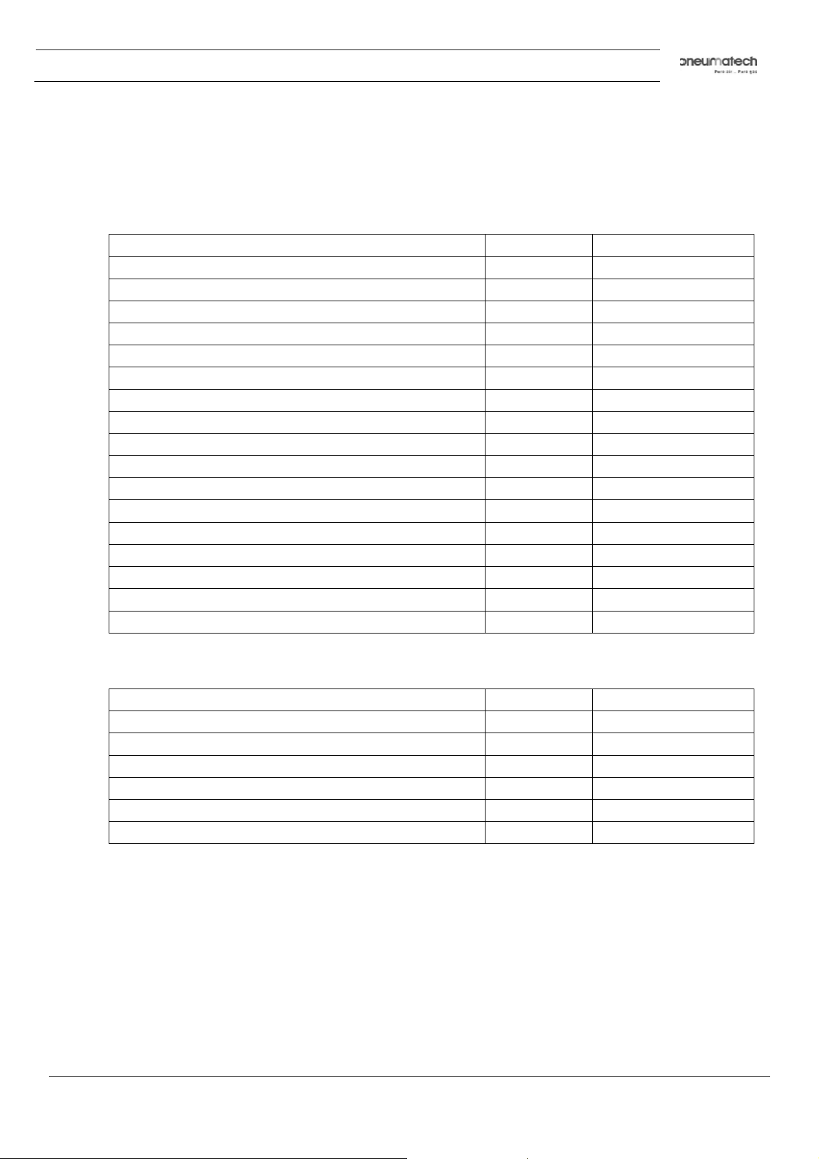
Reference conditions
Compressed air inlet pressure bar(e) 7
Compressed air inlet pressure psig 101.53
Compressed air inlet temperature
- 50 Hz dryers ˚C 35
- 50 Hz dryers ˚F 95
- 60 Hz dryers ˚C 38
- 60 Hz dryers ˚F 100
Ambient temperature
- 50 Hz dryers ˚C 25
- 50 Hz dryers ˚F 77
- 60 Hz dryers ˚C 38
- 60 Hz dryers ˚F 100
Pressure dewpoint
- 50 Hz dryers ˚C 3
- 50 Hz dryers ˚F 37.4
- 60 Hz dryers ˚C 4
- 60 Hz dryers ˚F 39
Unit
Limits
Unit
Maximum compressed air inlet pressure bar(e) 14
Maximum compressed air inlet pressure psig 203
Min.-max. ambient air temperature ˚C 1-46
Min.-max. ambient air temperature ˚F 39-115
Max. compressed air inlet temperature ˚C 60
Max. compressed air inlet temperature ˚F 140
9828 0931 61 41
Page 42
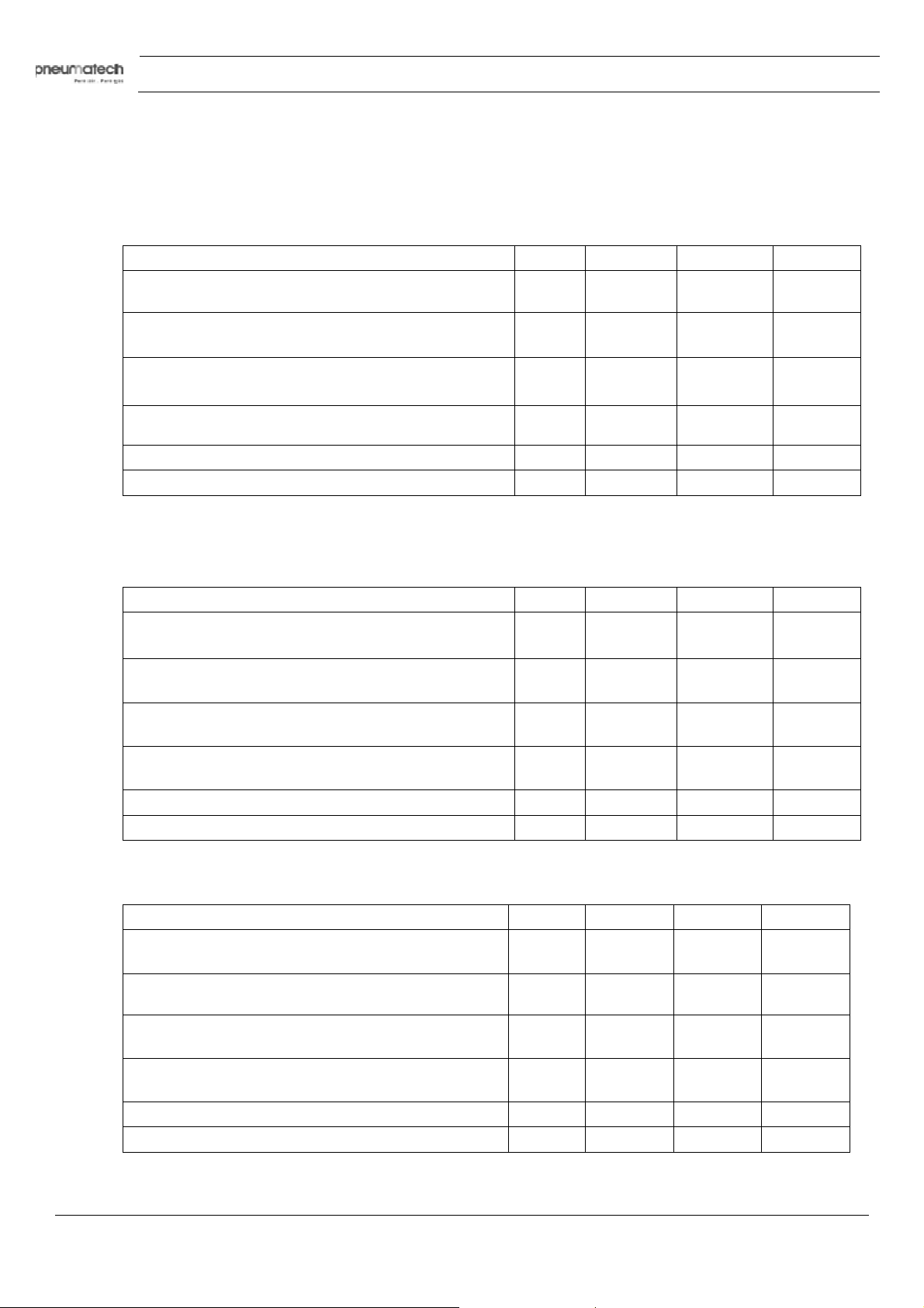
114.8
°F, Inlet temperature 140 °F)
8.2 Air dryer data
50 Hz
400 V
Air dryer type Unit AD 750 AD 1000 AD 1250
Nominal electric power input (Ambient temperature
25 °C, Inlet temperature 35 °C)
Nominal electric power input (Ambient temperature
77 °F, Inlet temperature 95 °F)
Maximum electric power input (Ambient temperature
46 °C, Inlet temperature 60 °C)
Instruction book
kW 3.26 3.89 4.75
hp 4.43 5.29 6.46
kW 5.26 5.98 7.2
60 Hz
Maximum electric power input (Ambient temperature
Weight of the unit kg 325 335 350
Weight of the unit lb 716.5 738.5 771.6
380 V
Air dryer type Unit AD 750 AD 1000 AD 1250
Nominal electric power input (Ambient temperature
38 °C, Inlet temperature 38 °C)
Nominal electric power input (Ambient temperature
100.4°F, Inlet temperature 100.4 °F)
Maximum electric power input (Ambient temperature
46 °C, Inlet temperature 60 °C)
Maximum electric power input (Ambient temperature
114.8°F, Inlet temperature 140 °F)
Weight of the unit kg 358 368 383
Weight of the unit lb 789 811 844
hp 7.15 8.13 9.79
kW 5.65 6.07 7.63
hp 7.68 8.25 10.37
kW 6.86 7.1 8.91
hp 9.33 9.66 12.12
460 V
Air dryer type Unit AD 750 AD 1000 AD 1250
Nominal electric power input (Ambient temperature
38 °C, Inlet temperature 38 °C)
Nominal electric power input (Ambient temperature
100.4°F, Inlet temperature 100.4°F)
Maximum electric power input (Ambient temperature
46 °C, Inlet temperature 60 °C)
Maximum electric power input (Ambient temperature
114.8°F, Inlet temperature 140 °F)
Weight of the unit kg 325 335 350
Weight of the unit lb 716.5 738.5 771.6
42 9828 0931 61
kW 5.45 5.87 7.43
hp 7.41 7.98 10.1
kW 6.65 6.9 8.71
hp 9.04 9.38 11.84
Page 43
Instruction book
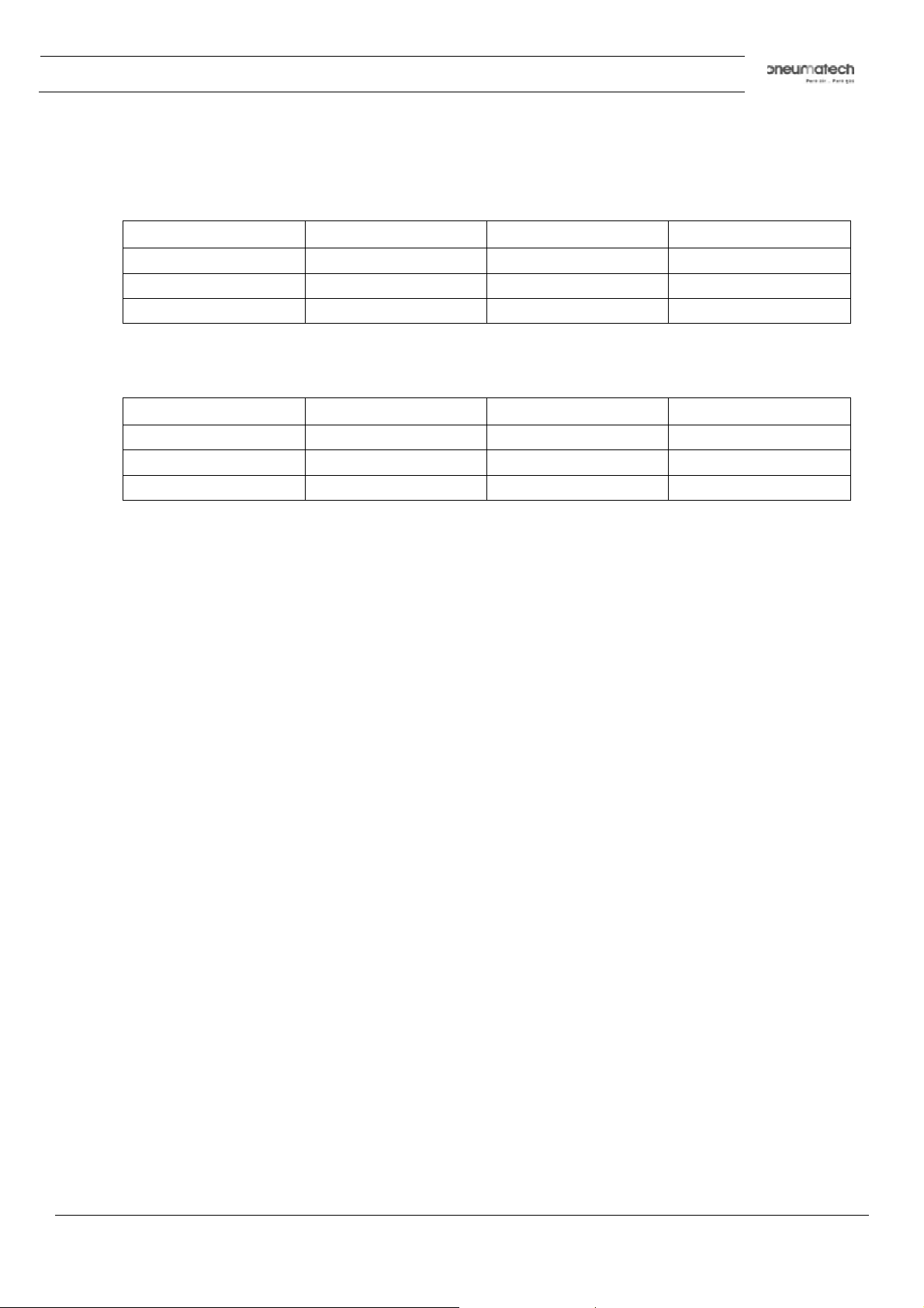
Refrigerant gas and global warming potential
The refrigerant gas for the dryer is R410A and the global warming potential is 2088.
Amount of refrigerant gas and tonnes of CO2 equivalent for 50 Hz dryers
Dryer Amount (kg) Amount (lbs)
AD 750
AD 1000
AD 1250
Amount of refrigerant gas and tonnes of CO2 equivalent for 60 Hz dryers
Dryer Amount (kg) Amount (lbs)
AD 750
AD 1000
AD 1250
3.6 7.94 7.52
3.8 8.38 7.93
4.5 9.92 9.40
3.7 8.16 7.73
4.3 9.48 8.98
4.5 9.92 9.40
CO2 equivalent
CO2 equivalent
9828 0931 61 43
Page 44

Instruction book
44 9828 0931 61
Page 45

www.pneumatech.com
 Loading...