

Page 1
Document No. : PVIM/110/01
Revision No. : 00
Date. : 01.0
6
.2019
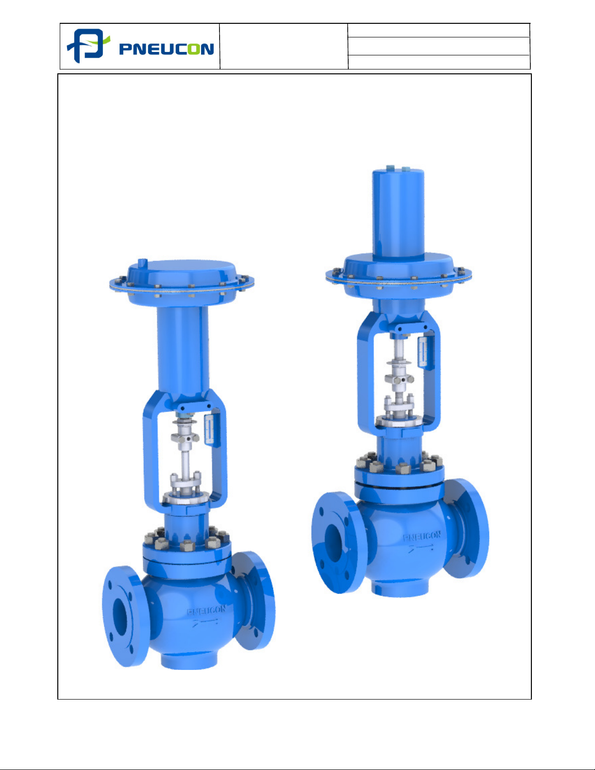
INSTALLATION, MAINTENANCE AND OPERATION
MANUAL OF GLOBE 2 WAY CONTROL VALVES
AND DIAPHRAGM ACTUATOR.
06/19 1 of 23
Page 2
Document No. : PVIM/110/01
Revision No. : 00
Date. : 01.0
6
.2019
Section
1 General 3
2 Warnings 4
3 Storage and Handling 5
4 Pre-Installation 6
5 Installation 7-8
6 Control Valve Maintenance 9-18
7 Actuator Maintenance 19-20
8 Actuator to Valve Assembly 21
9
Mounting Accessories / Schematic Line Diagram of Accessories
10 Troubleshooting 23
Contents
Description Page.
22
06/19 2 of 23
Page 3
Document No. : PVIM/110/01
Revision No. : 00
Date. : 01.0
6
.2019
1. GENERAL
The Globe 2 way control valve range is a linear rising stem design
which is suitable for a wide range of process control applications.
This proven design is manufactured in accordance with international
control valve standards and can be supplied with a wide range of
trim design options ranging from low capacity types, standard
designs through to multi stage severe service options. The Globe 2
way control valve is supplied with the diaphrsgm actuator spring
opposed pneumatic diaphragm actuator along with the various
options available.
In additional, the Globe 2 way control valve could be fitted with other
actuator types including pneumatic piston, electric, hydraulic and
electro hydraulic types. For these types of actuator please refer to the
specific product OIM documents, which would be supplied as part of
the project documentation package.
This manual provides the guidelines for Globe 2 way control valve
and Diaphragm Actuator covering the standard sizes and ratings
manufactured. The manual covers the handling, storage, installation,
operation and maintenance requirements for these products.
If ancilliary equipment is mounted on the valve and actuator eg.
Positioner, Airset, Solenoid Valve, Airlock, Volume Booster, I/P
Converter, Position Transmitter or Limit Switch a copy of the
respective OIM will be provided within the documentation package.
Instructions not detailed in this document shall be performed in
accordance with standard and safe acceptable practices as may be
required by local codes, specifications and or regulations.
The instructions contained within this manual must be read before
undertaking any work on the equipment supplied and if there are
any questions please contacts Pneucon valves.
When ordering any spares please specify the unique valve serial
number detailed on the equipment nameplate.
06/19 3 of 23
Page 4
Document No. : PVIM/110/01
Revision No. : 00
Date. : 01.0
6
.2019
2. WARNINGS
a) In order to avoid possible injury to personnel or damage to any equipment any
‘WARNING and CAUTION’ notes must be strictly adhered to.
b) Modification of this product, substitution of non-approved components and use
of maintenance procedures other than those detailed within this document could
drastically affect the performance, nullify any warranty and be hazardous to
personnel and equipment.
c) Personal injury, equipment damage, leakage due to escaping gas or failure of
pressure containing component may result if the valve or ancillaries are over
pressured or installed where service condition exceed the limits detailed in the
manufacturer’s specification or on the valve nameplate. To avoid such injury or
damage a relief valve for over pressure protection should be provide as required
by industry and sound engineering practices or applicable safety codes.
d) Due to the possibility of both elevated and low temperatures occurring on
exposed surfaces of the valve assembly during operation, adequate safety
precautions must be taken. This may involve insulating the valve assembly or
the provision of safety clothing and equipment to avoid personal injury.
e) It is a requirement of PER 1999 that both the maximum working pressure and
temperature of the valve are detailed on the nameplate. The stated values must
be adhered to separately and in isolation. Attention must be paid to the
combined pressure and temperature characteristics of the appropriate valve
pressure containment material group as stated in ASME / ANSI B 16.34.
f) When purchased each valve / trim configuration and construction materials are
specifically selected to satisfy the particular application, conditions of flow,
temperature, pressure drop and controlled fluid conditions for corrosion and
erosion. Included within the Pneucon Valve selection process is the
consideration of the amount of power conversion allowed to reduce vibration
levels within the valve and also the materials of construction are specifically
selected for each application. The valve must not be used on any other
application, without a review by Pneucon Valve.
g) The valve is not suitable for fire safe service and is not certified for this
application or duty. Unless otherwise detailed in the quotation and order
documentation the valve will not have been designed to deal with excessive
seismic activity or bending moments resulting from misaligned pipe work.
h) It is not intended that externally applied lever arms will be used on the valve and
actuator assembly.
i)
For cage guided valve, use of strainer is recommended to remove line debris to
protect any damage to valve internal so as to have smooth movement of plug in
cage.
06/19 4 of 23
Page 5
Document No. : PVIM/110/01
Revision No. : 00
Date. : 01.0
6
.2019
3. STORAGE AND HANDLING
3.1 Storage
a. Following receipt of the equipment, it should be inspected for any transit
damage. Any damage found should be photographed and a copy of the
photograph, together with notification of the damage found sent to Pneucon
Valve.
b. Any flange or valve protectors should be left fitted until immediately prior to
installation in the pipework.
c. If the valve is going to be stored prior to installation (typically up to 2 months)
it should be in a clean, dry and heated environment in the crate (or on the
pallet) on which it was delivered.
d. If the valve is going to be stored prior to installation for longer than the above
2 months please contact Pneucon Valve for recommendations based on the
planned length of time to be stored.
3.2 HANDLING
1. The weight of the control valve assembly can cause serious injury if it is not
handled correctly, includes using the appropriate lifting equipment and
personal protective clothing.
2. The appropriate lifting equipment must be used and properly attached. Where
lifting eyes are provided with the equipment these should be used to enable
safe handling of the valve, actuator or assembly. All lifting equipment should
be used within its defined limitations, applicable codes and safe industrial
practices.
3. The recognised safe industrial practices include the following.
• Slings to be free of kinks
• Lifting hooks to be positioned directly over the load to avoid any severe
movement when lifted
• The operator shall ensure that the load is safe and well secured
• When lifting the equipment ensure that any slings or hoists are positioned to
avoid any damage to the accessories or tubing mounted on the valve assembly
06/19 5 of 23
Page 6
Document No. : PVIM/110/01
Revision No. : 00
Date. : 01.0
6
.2019
4.
PRE
– INSTALLATION
1. In preparation for the installation sufficient clearance above and around the
valve and actuator should ideally be provided for access and maintenance
purposes.
2. Prior to installation, the space in the pipework in which the control valve is to
be installed should be checked to be in accordance with the GA drawing
supplied with the valve or to the recognised international standard for face to
face dimensions.
3. For control valves using a pneumatic air supply as the power source and fitted
with instruments an air supply filter/regulator should be provided to protect
the pneumatic actuator from over pressurisation and be within the operating
range of the pneumatic actuator to be used.
4. For control valves fitted with a ‘smart’ electro pneumatic positioner the
filter/regulator should be suitable for being filtered to ISO 8573-1 class 2 or
better.
5. If the pipework in which the control valve is going to be installed is going to be
flushed prior to operation of the valve, consideration of removing the internal
trim parts prior to the flushing process should be made, to prevent any
subsequent damage or blockage within the trim. For this requirement please
contact Pneucon Valve for a more detailed procedure and details of flushing kit
to be supplied.
6. Similarly for control valves supplied with butt weld end connections and fitted
with PTFE based internal parts eg pressure balance seal the trim parts should
be removed to enable the body to be welded into the pipework.
7. The assembly should be inspected on receipt to ensure that it has not been
damaged during transit. This inspection should be undertaken in a safe and
controlled manner as valve equipment can be heavy and have sharp edges. Any
damage found should be photographed and immediately reported to Pneucon
Valve.
8. The end caps or other protection devices should not be removed from the
equipment until the time of installation, in order to help avoid any damage to
the flanges and also prevent the ingress of dirt or foreign particles.
9. The adjacent pipework must be free of dirt, pipe scale, welding slag and all
other foreign objects. Safe operation of the valve could be impaired by the
ingress of line debris or foreign matter.
06/19 6 of 23
Page 7
Document No. : PVIM/110/01
Revision No. : 00
Date. : 01.0
6
.2019
5. INSTALLATION
• The valve is supplied with a flow direction arrow either cast on to the body,
detailed on a separate arrow plate or detailed on the nameplate. It is very
important that the valve is installed into the pipework with the correct flow
direction.
• Install the valve using accepted piping practises and preferably with suitable
lengths of straight pipework both upstream and downstream.
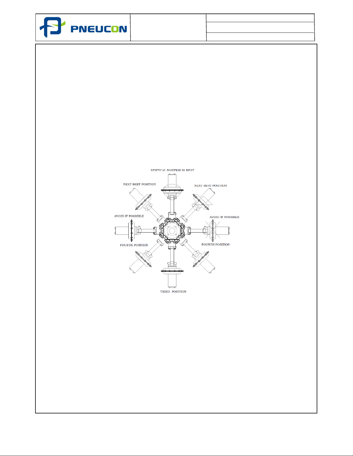
• The preferred orientation is for the actuator to be vertically upright. If a valve is
required to be installed in any other orientation the valve and actuator must be
adequately supported. The following is a diagram showing the preferred options
for the installation of control valves fitted with a pneumatic diaphragm.
• If a normalising bonnet is provided for a high or low temperature application
and the pipework is thermally lagged the lagging must be terminated at the
bonnet to body flange bolting.
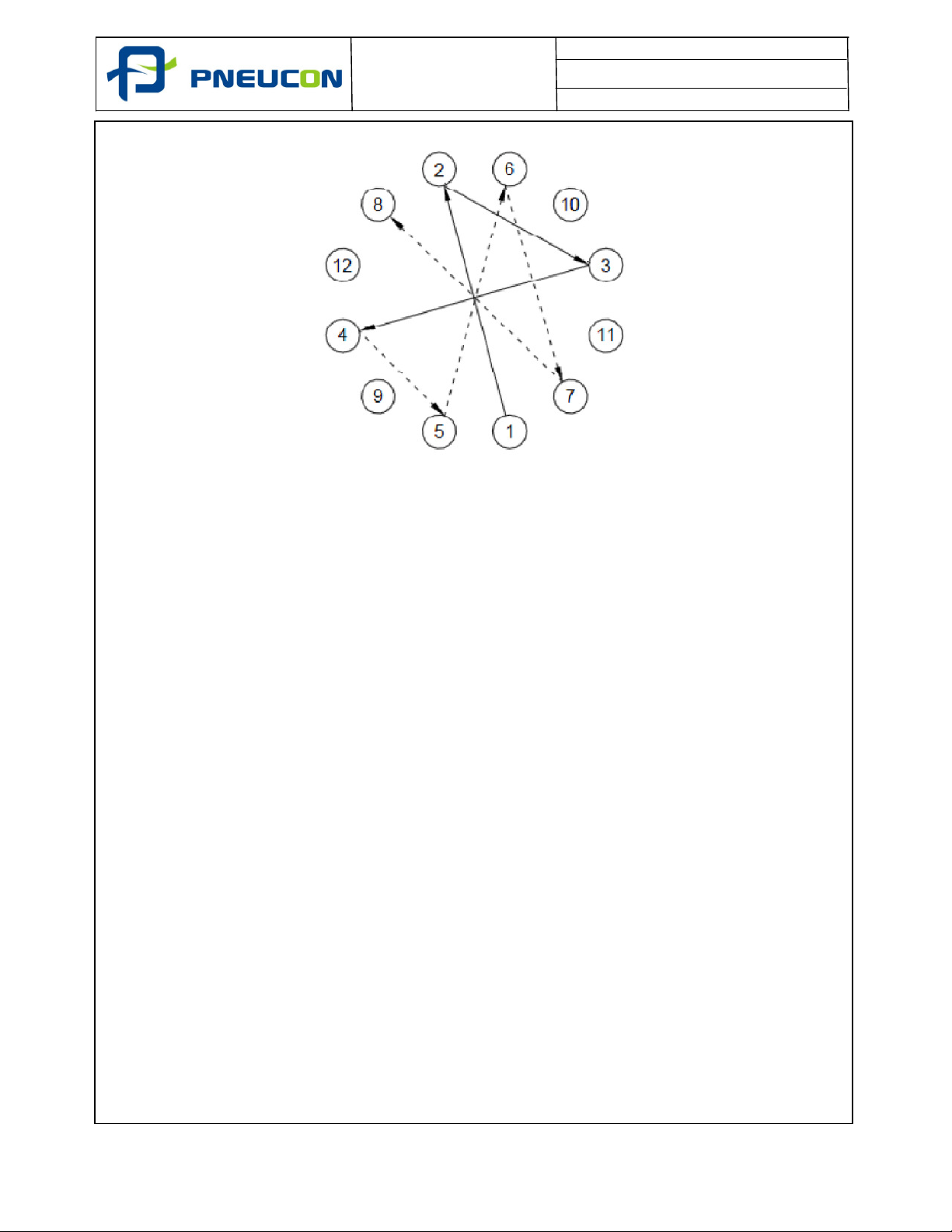
•
If the control valve is provided with flanged connections the fasteners should be
tightened evenly using the ‘cross rotation’ method illustrated on page no 8 of
23.
06/19 7 of 23
Page 8
Document No. : PVIM/110/01
Revision No. : 00
Date. : 01.0
6
.2019
• For control valves supplied with butt weld end connections welding into the
pipework shall be undertaken by qualified welders and approved weld
procedures. Any subsequent local post weld heat treatment should be carried
out in accordance with the approved procedure. It is recommended that the
valves are in the closed position during the welding process.
• If the trim has been removed for welding the valve into the line or for flushing
purposes it should be replaced with new gaskets.
• Following installation of a valve and actuator fitted with an handwheel
mechanism the actuator mechanism should be checked to ensure that it is in
the ‘neutral’ position. An input signal should then be applied to the valve
actuator in order to check and confirm correct calibration of the assembly.
• All pneumatic air connections should be checked for leaks. During functional
testing of a spring return diaphragm actuator, the assembly would have been
subject to a pressure test at 3.4 barg.
•
The gland nuts are factory adjusted and following commissioning further
adjustment could be required to stop any stem leakage. It should be pointed
out that excessive tightening of the gland studs could result in packing wear or
excessive friction.
06/19 8 of 23
Page 9
Document No. : PVIM/110/01
Revision No. : 00
Date. : 01.0
6
.2019
6. MAINTENANCE
6.1 General
The maintenance recommendations for a control valve and actuator assembly are a function
of the criticality of the valve as part of the overall control system and also consideration of
the severity of the duty. These factors need to be considered in determining when and how
frequently a control valve should be inspected and maintained. For further recommendations
for specific applications please contact Pneucon Valve.
With regards to the soft parts used within the construction of a control valve and pneumatic
diaphragm actuator assembly the following are some general guidelines for periods when
these various parts should be replaced.
• Valve body, bonnet and seat gaskets (where applicable) – These should be replaced
every time the valve is dis-assembled and re-assembled plus every 3 years between
installation or replacement.
• Valve gland packing - These again should be replaced every time the valve is dis-
assembled and re-assembled plus every 3 years between installation or replacement.
• Valve pressure balance seal (where applicable) – Only needs to be replaced if found to
be damaged or worn plus every 4 years between installation or replacement.
• Valve seat soft face (where applicable) – Only needs to be replaced if found to be
damaged or worn plus every 4 years between installation or replacement.
• Actuator diaphragm – Only needs to be replaced if found to be damaged or worn plus
every 4 years between installation or replacement.
• Actuator O-rings (where applicable) – Only need to be replaced if found to be damaged
or worn plus every 4 years between installation or replacement.
6.2 Removal of Actuator from Valve
• Ideally this work should be undertaken in a workshop or if not, ensure that the valve
is correctly isolated and the pipework de-pressurised.
• If still installed in the pipework remove the instrument signal to the positioner and air
supply to the airset. If practical attach a temporary regulated air supply to the airset.
• Disconnect and remove any instrument linkages connected to the valve and actuator
interface.
• Lift the valve plug off the seat ring using the temporary airsetand remove the stem
coupling.
• Unscrew and remove the locking ring from the bonnet threads.
• Check that the handwheel (if fitted) is in the ‘neutral’ position.
• Remove the actuator from the valve.
06/19 9 of 23
Page 10
Document No. : PVIM/110/01
Revision No. : 00
Date. : 01.0
6
.2019
MICRO
SPLINE TRIM
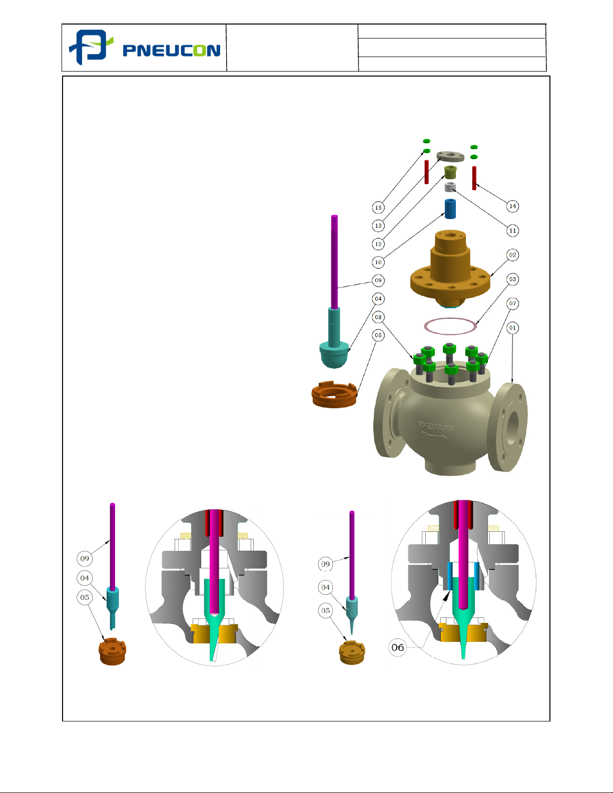
6.3 Disassembly Of Globe 2 Way Control Valve with Contoured, Microspline & Multistep
Trim (Metal To Metal)
1. Remove the gland Stud Nut (Part No - 15),
Gland Pusher (Part No - 13) & Gland (Part
No - 12).
2. Remove the Body Bonnet Stud Nut (Part
No - 8) and lift the Bonnet (Part No - 2)
from the valve body, while holding the plug
stem assembly (Part No - 4 & 9).
3. Remove the plug stem assembly.
4. Remove Gasket from the body to bonnet
(Part No - 3).
5. Remove the packing set (Part No - 11) and
Spacer (Part No - 10) from the Bonnet.
6. Removal of the Seat Ring (Part No - 5) is
only necessary for replacement or
machining.
Where necessary the seat ring is screwed
out of the body and a lathe or boring mill
can be used for seat ring that are difficult
to remove.
For extremely tight seat rings the valve
body should be heated to assist removal.
7. For Top Guided Valves, the Plug Guide
Bush (Part No - 6) is pressed into the
bonnet and does not normally require
removal. When removal of the guide is
essential it should be machine. Plug Guide
Bush (Part No - 6) is not applicable in
Microspline trim Design.
8. All the parts should be cleaned and
examined for damage.
MULTISTEP TRIM
06/19 10 of 23
Page 11
Document No. : PVIM/110/01
Revision No. : 00
Date. : 01.0
6
.2019
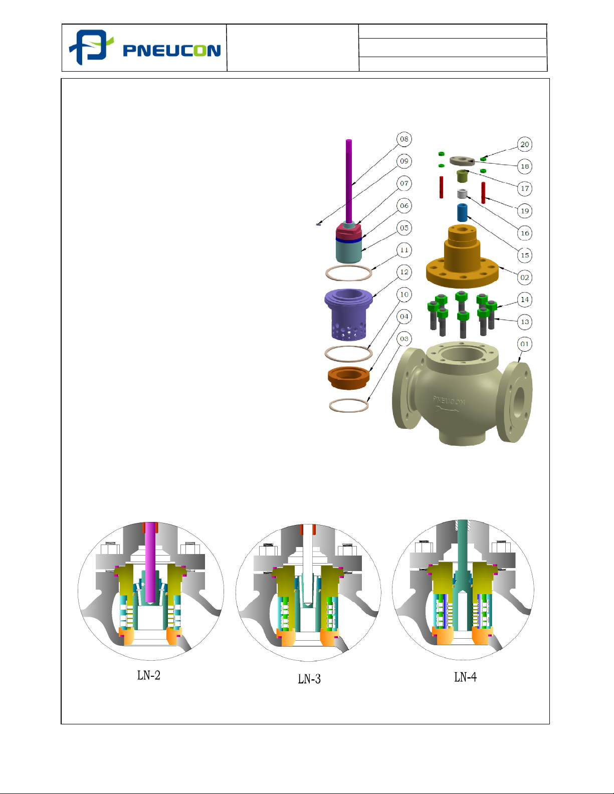
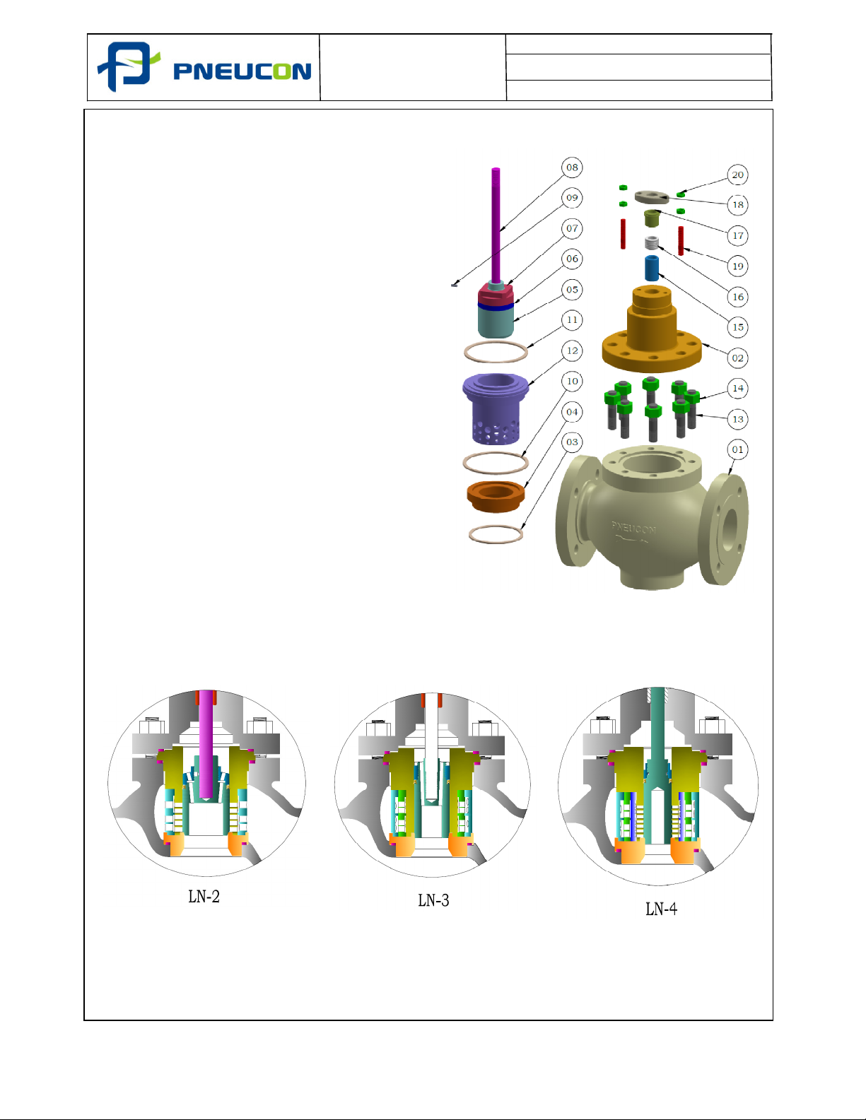
6.4 Disassembly Of Globe 2 Way Control Valve with Cage Guide Trim
1. Remove the gland stud nut (Part No -
20), Gland Pusher (Part No - 18) &
Gland (Part No - 17).
2. Remove the Body Bonnet Stud Nut
(Part No - 14) and lift the Bonnet (Part
No - 02) from the valve body, While
Holding the plug stem assembly (Part
No - 05,06,07,08 & 09)
3. Remove the packing set (Part No - 16)
and Spacer (Part No - 15) from Bonnet.
4. Remove the plug stem assembly.
5. Remove Gasket from the bonnet Joint
Gasket (Part No - 11).
6. Remove Inner Cage (Part No -12)
7. Remove Gasket from Body Joint Gasket
(Part No - 10).
8. Removal of the Seat Ring (Part No - 04)
is only necessary for replacement or
machining.
9. Above all step are also use in LN2, LN3,
& LN4.
10. All the parts should be cleaned and
examined for damage
06/19 11 of 23
Page 12
Document No. : PVIM/110/01
Revision No. : 00
Date. : 01.0
6
.2019
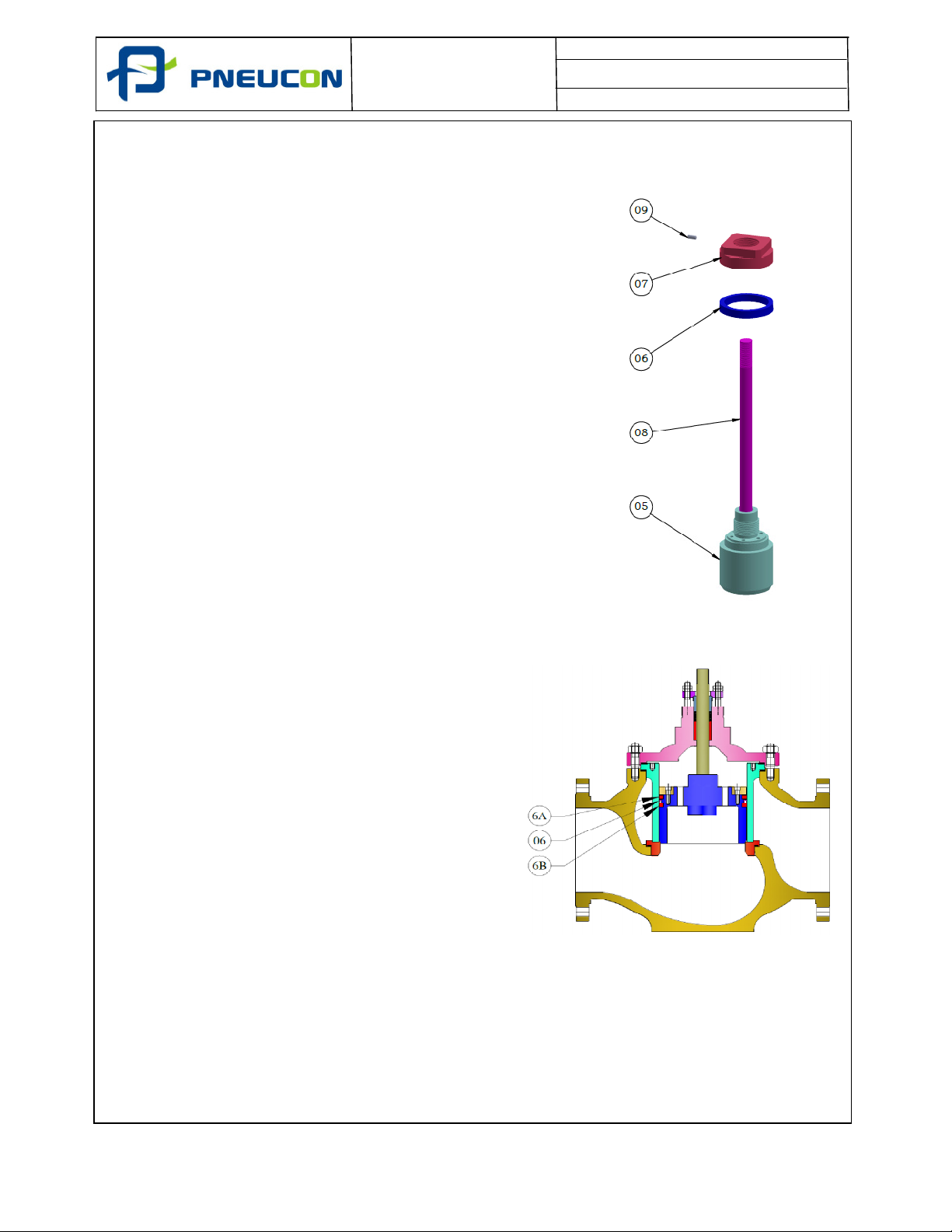
6.5 Replacing Pressure Balanced Seal
6.5.1 PTFE Seals in Trim Sizes up to 6”
1.
Remove the Grub Screw (Part No - 09)for the
Retainer nut.
2.
Remove the Retainer Nut (Part No - 07) from
the Plug Stem Assembly.
3.
Remove the old Balancing Ring (Part No -
06) and Replace the new one Balancing
Ring.
4.
In the Balancing Ring there are Various type
of Balancing Ring (Part No - 06).
a) PTFE = -100°C to 180°C.
b) GFT = -50°C To 210°C.
c) Carbon Filled PTFE = 0°C to 220°C.
d) Carbon Ring = 200°C to 550°C for High
Temperature.
6.5.2 PTFE Seals in Trim Sizes above 6”
• Unscrew cap heads and remove seal
retainer plate
• Remove upper anti extrusion ring (6A)
• Remove main pressure balance seal (6)
• Remove lower anti extrusion ring (6B)
• Replace with new pressure balance seal
ensuring orientation is correct (spring
upwards for ‘flow under’ and spring
downwards for ‘flow over’
•
Refit anti extrusion rings, seal retainer
plate and
fit caphead screws
06/19 12 of 23
Page 13
Document No. : PVIM/110/01
Revision No. : 00
Date. : 01.0
6
.2019
6.5.3
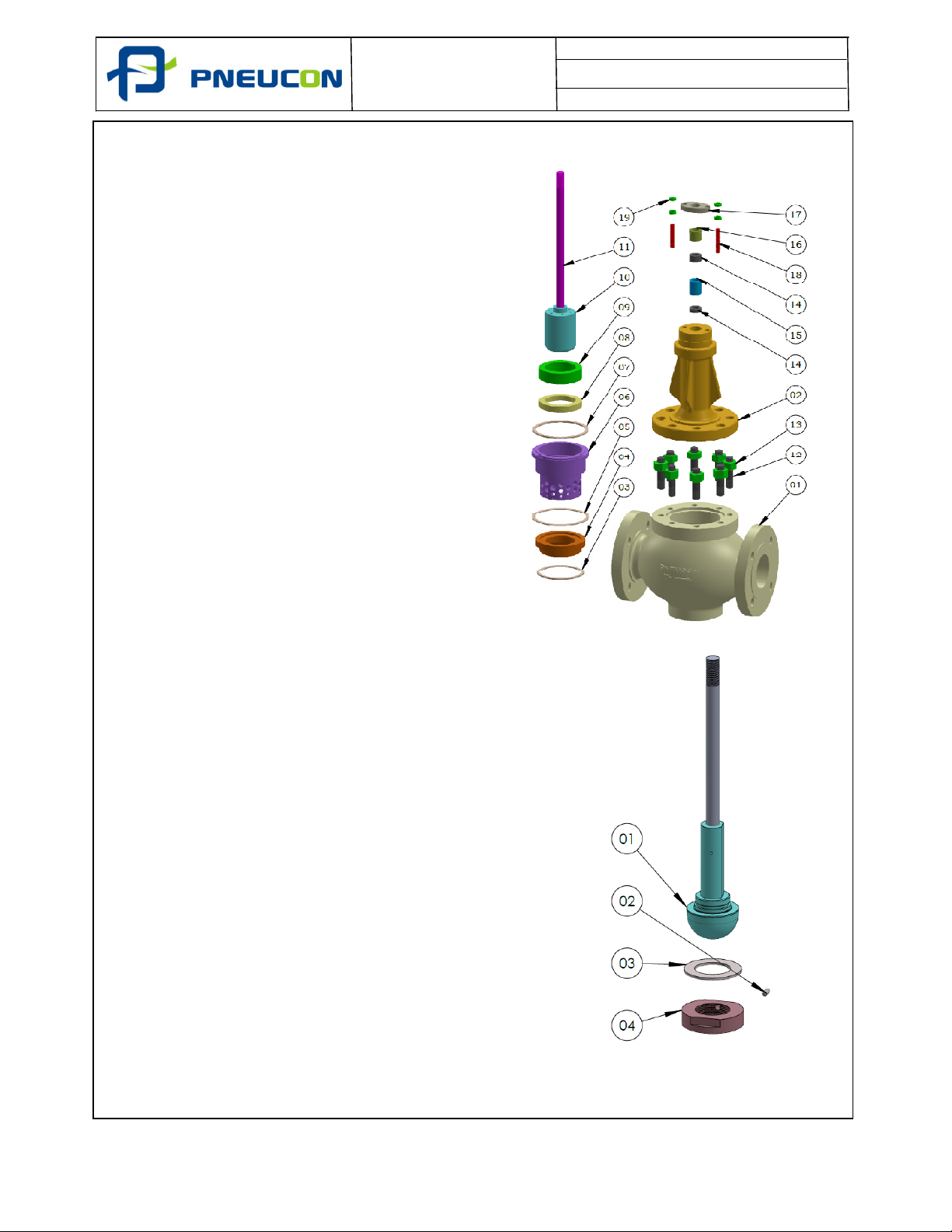
Disassembly Of Globe 2 Way Control Valve with Cage Guided Trim (Grafoil
Design)
1. Remove the gland stud nut (Part No -
19), Gland Pusher (Part No - 17) &
Gland (Part No - 16).
2. Remove the Body Bonnet Stud Nut
(Part No - 13) and lift the Bonnet (Part
No - 02) from the valve body, While
Holding the plug stem assembly (Part
No - 08,09,10 & 11)
3. Remove the packing set (Part No - 14)
and Spacer (Part No - 15) from Bonnet.
4. Remove the plug stem assembly.
5. Remove Gasket from the bonnet Joint
Gasket (Part No - 07).
6. Remove Inner Cage (Part No -06)
7. Remove Gasket from Body Joint Gasket
(Part No - 05).
8. Removal of the Seat Ring (Part No - 04)
is only necessary for replacement or
machining.
9. All the parts should be cleaned and
examined for damage
6.6 Replacing Soft Seat
6.6.1 Replacing Contoured Trim Soft Seat
• Remove plug assembly from control
valve as per section 6.3
• Unscrew seal retaining ring (Part No -
04).
• Remove soft seat insert (Part No - 03)
• Replace soft seat insert
• Screw seal retaining ring on to plug
06/19 13 of 23
Page 14
Document No. : PVIM/110/01
Revision No. : 00
Date. : 01.0
6
.2019
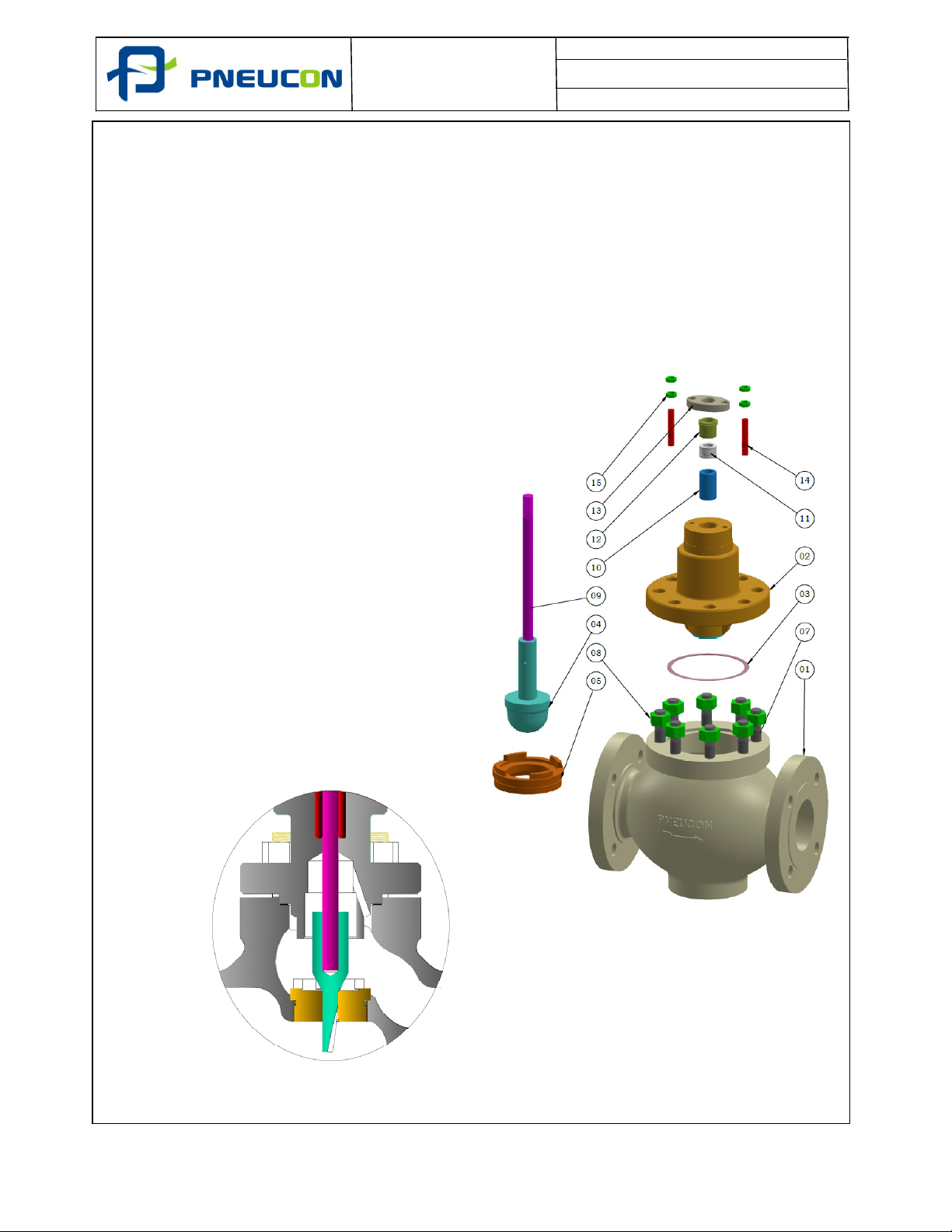
6.7 Valve Assembly
6.7.1 General
• New plugs are normally supplied with stems which are integral or fitted into the plug
head. If the parts are separate the stem should be screwed into the plug head and
tightened. The plug shank and stem should be drilled and countersunk. The pin is
then fitted and pin peened over, before being finally machined flush to the plug shank.
• All the parts of the assembly should be cleaned and free from any debris.
6.7.2 Assembly with Contoured, Spline Micro or Multistep Trims
• Apply sealing compound to the seat
(5) and screw into body (1). The seat
ring should be tightened using a seat
tool (contact Pneucon Valve for
further details)
• Install the plug (4) and stem (9)
assembly
• Place body joint (3) in body recess
• Carefully lower the bonnet (2) over the
plug stem and also over the body
studs (7). The bonnet should be
centred to ensure that the plug and
stem assembly move freely
• Fit the body nuts (8) and tighten
evenly using the ‘star logic’ sequence.
The valve should be moved in a linear
direction only, to ensure free
movement of the stem
• Refer to 6.8 for assembly of gland
packing options
06/19 14 of 23
Page 15
Document No. : PVIM/110/01
Revision No. : 00
Date. : 01.0
6
.2019
6.7.3 Assembly with Cage Guided Trim
• Place seat gasket (3) in body and
install seat (4)
• Place cage gasket (10) in body(1) and
place cage (12) in body
• Install the plug and stem assembly
• Place body joint (11) in body recess
• Carefully lower the bonnet (2) over
the plug stem and also over the body
studs. The bonnet should be centred
to ensure that the plug and stem
assembly move freely
• Fit the body nuts (14) and tighten
evenly using the ‘star logic’ sequence.
The valve should be moved in a
linear direction only, to ensure free
movement of the stem
• Refer to 6.8 for assembly of gland
packing
06/19 15 of 23
Page 16
Document No. : PVIM/110/01
Revision No. : 00
Date. : 01.0
6
.2019
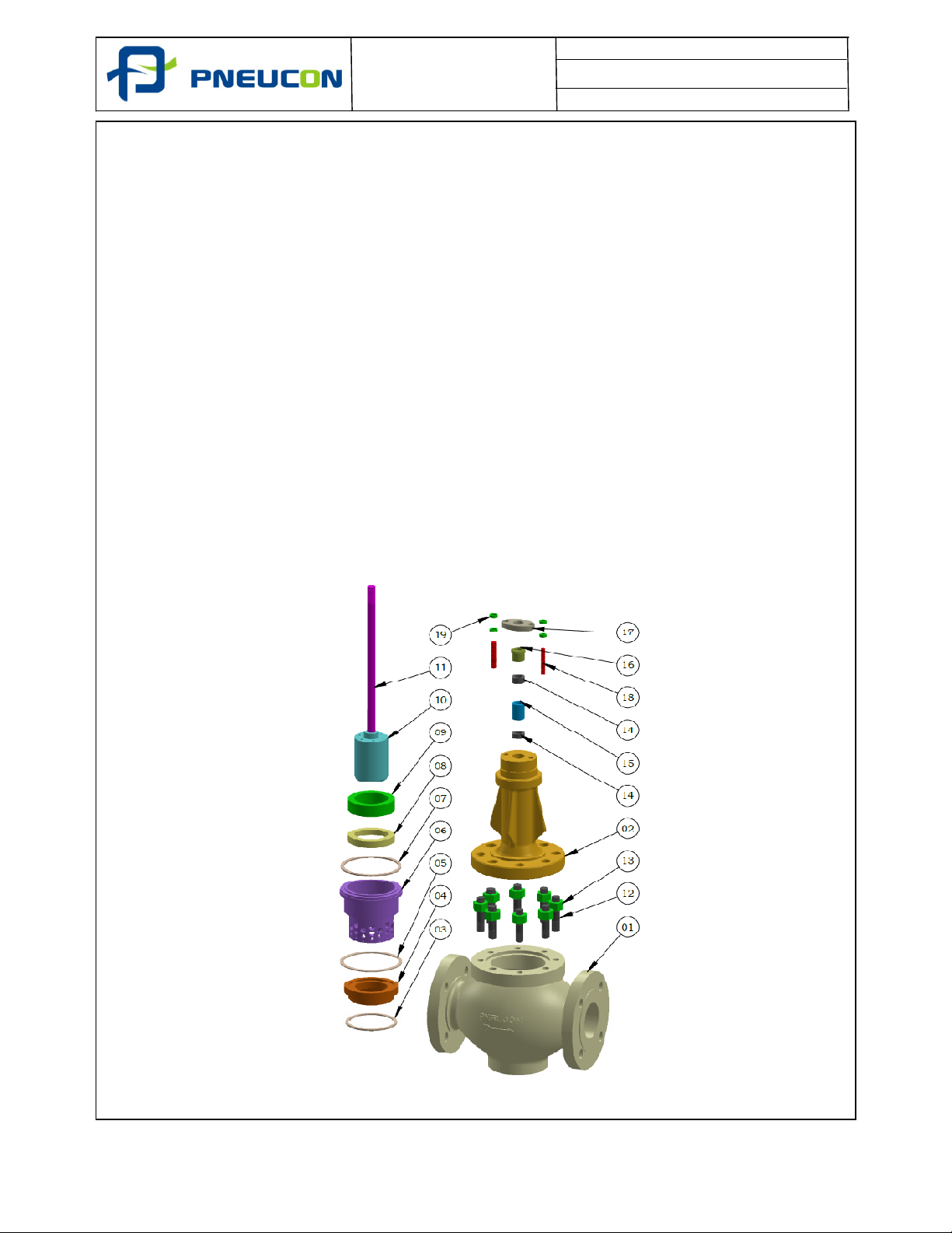
6.7.4
Assembly with Cage Guided Trim and Graphite Pressure Balance Seal
• Place seat gasket (5) in body and fit seat (4)
• Place cage gasket (10) in body (1) and place cage (6) in body
• Install graphite seal (8)
• Install seal retainer (9)
• Install the plug and stem assembly (10 + 11)
• Place body joint (7) in body recess
• Carefully lower the bonnet (2) over the plug stem and also over the body studs.
The bonnet should be centred to ensure that the plug and stem assembly move
freely
• Fit the body nuts (13) and tighten evenly using the ‘star logic’ sequence. The
valve should be moved in a linear direction only, to ensure free movement of
the stem
• Refer to 6.8 for assembly of gland packing
06/19 16 of 23
Page 17
Document No. : PVIM/110/01
Revision No. : 00
Date. : 01.0
6
.2019
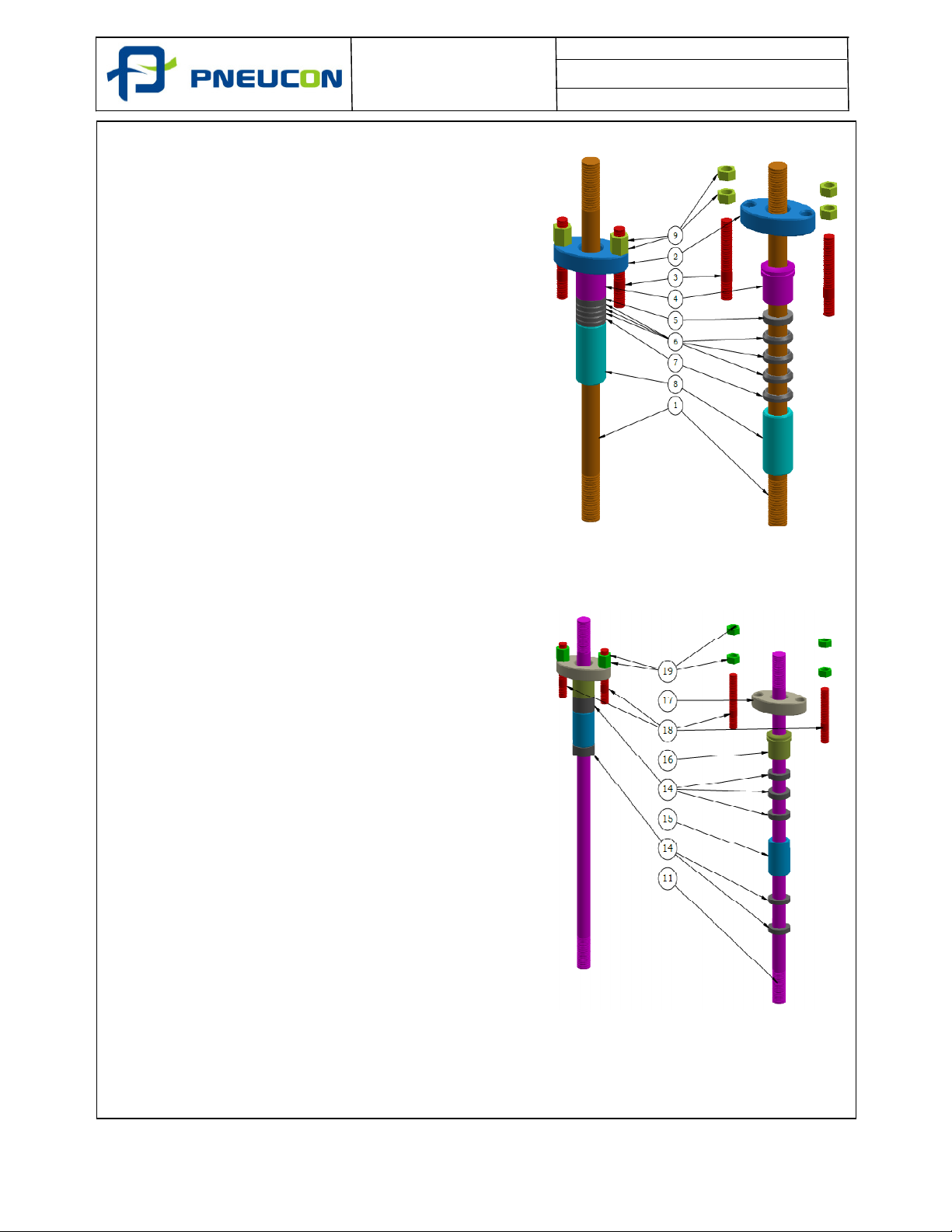
6.8 Gland Packing Assembly
6.8.1 PTFE Gland Packing Assembly
1. All the parts should be cleaned and examined
for damage before the packing box assembly.
2. Insert first Packing Spacer (Part No - 08).
3. Insert Gland Packing PTFE (Part No - 05,06 &
07) Total set of ring should be fully installed.
4. Insert Gland (Part No - 04).
5.
Insert Gland Pusher (Part No - 02)and tight
with Gland Stud & Gland Stud Nut (Part No -
03 & 09)
6.8.2 Graphite Gland Packing Assembly
1. All the parts should be cleaned and examined
for damage before the packing box assembly.
2. Insert first two Nos of Gland Packing Grafoil
one by one and ensure the each ring should be
fully installed (Part No - 14).
3. Insert Packing Spacer (Part No - 15).
4. Insert Gland Packing Grafoil (Part No - 14) one
by one and ensure the each ring should be
fully installed.
5. Insert Gland (Part No - 16).
6.
Insert Gland Pusher (Part No - 17)and tight
with Gland Stud & Gland Stud Nut (Part No -
18 & 19)
06/19 17 of 23
Page 18
Document No. : PVIM/110/01
Revision No. : 00
Date. : 01.0
6
.2019
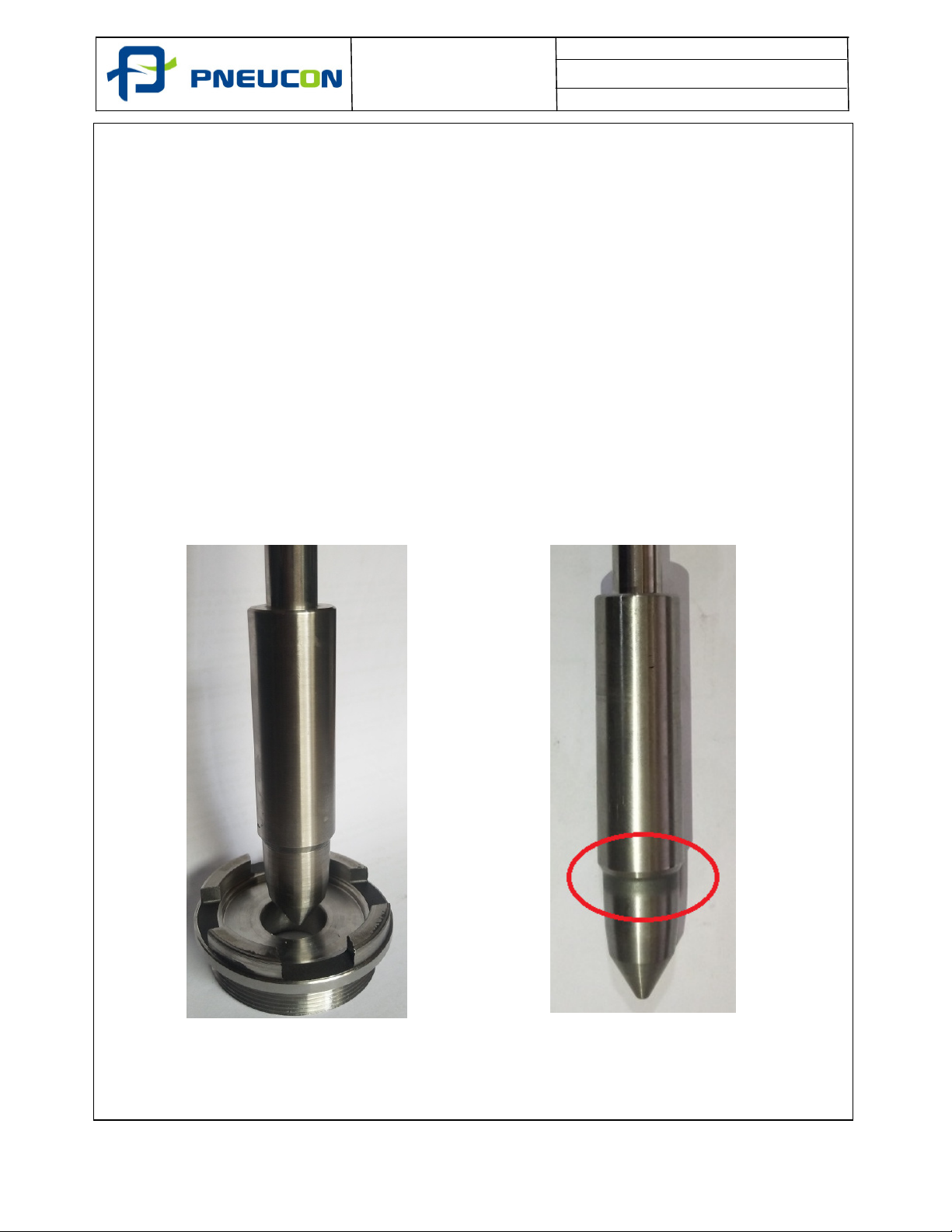
6.9
SEAT AND
PLUG LAPPING PROCESS.
• Lapping of the plug to the seat (if required) is normally carried out during the control
valve assembly and without the actuator fitted
• The valve bonnet should be fitted with the gland parts and the stem installed with a
light oil applied to assist the lapping process
• Apply a lapping compound to either the seat or plug seating face (not both) and fit the
bonnet assembly on to the body and loosely tighten a number of the bonnet nuts
ensuring the bonnet is centralised
• Lap the plug and seat using short oscillating movements, raising the plug occasionally
and lowering it to another position to ensure lapping of the entire plug and seat
seating faces
• The plug and seat should show evidence of the lapping continuously around the
seating faces
• Prior to final assembly of the bonnet to the body both the plug and seat parts should
be cleaned
BEFORE LAPPING
AFTER LAPPING
06/19 18 of 23
Page 19
Document No. : PVIM/110/01
Revision No. : 00
Date. : 01.0
6
.2019
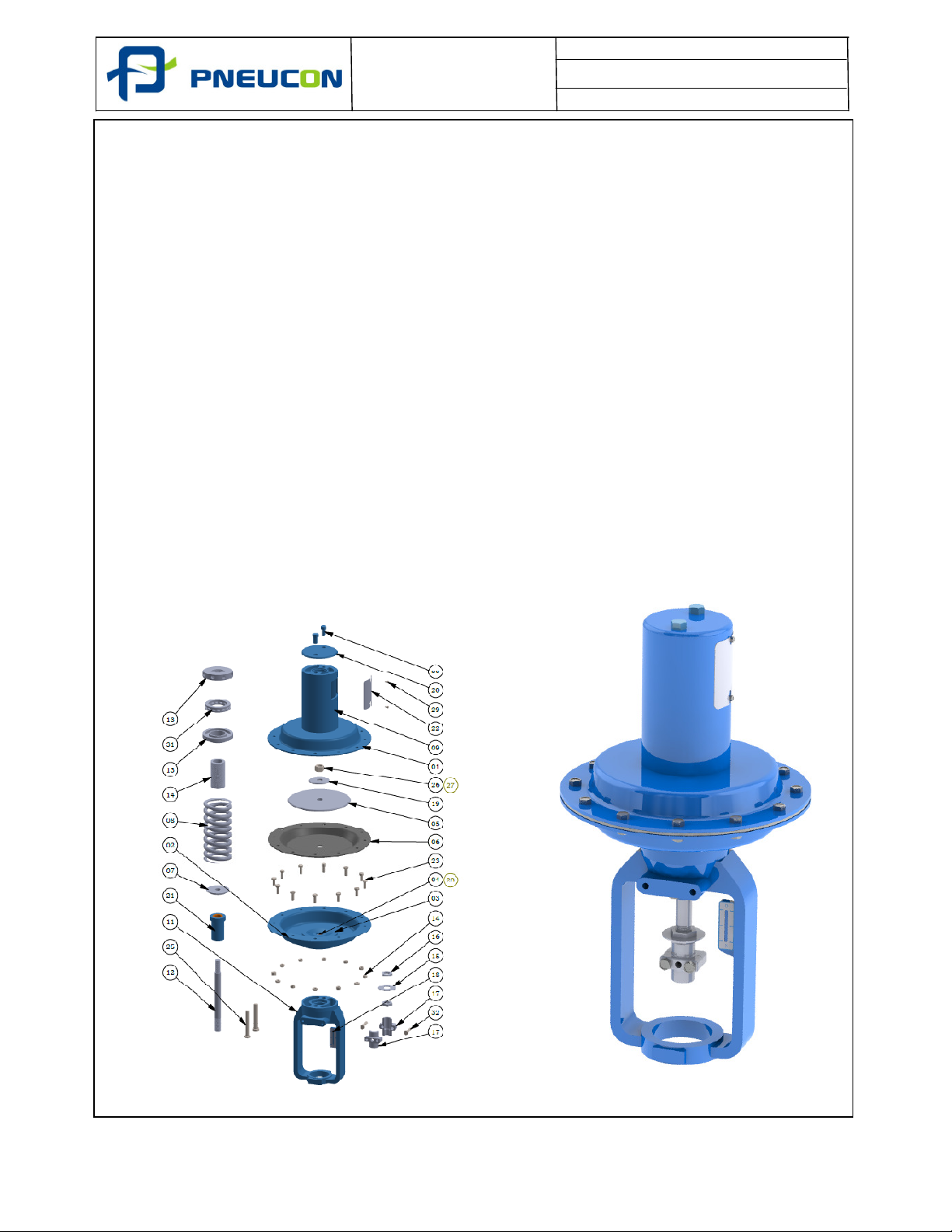
7 Actuator Maintenance
7.1 PDC Actuator Disassembly and Assembly
1. Open the Window Cover (Part No - 22).
2. Using the Spring Adjuster (Part No - 12) to release the Spring Compression (Part No -
08).
3. Remove the Casing Bolt and Nut (Part No - 23 & 14).
4. Remove the Top Casing (Part No - 01).
5. Remove the Hex Bolt from coupling (Part No - 32) and separate the coupling (Part No -
17).
6. Remove the Indicator lock nut (Part No - 16) and Travel indicator (Part No - 15) from
stem.
7. Unscrew the stem Lock Nut (Part No - 26) and remove the Spring Washer (Part No - 27)
and remove Spring Guide (Part No - 19) and remove the Area Plate (Part No - 05).
8. Remove the Diaphragm from the actuator (Part No - 06).
9. Clean all the internal parts and examine for any damage. Any significantly damaged
parts should be replaced.
10. For PDC actuator the two 'O' Ring (Part No - 28) in Seal Box (Part No - 04) should be
replaced.
11. After replacing the diaphragm Re-assemble the actuator.
12. Using the spring adjuster (Part No - 12) to compress the spring (Part No - 08) until the
actuator start to operate at the bench set figure detailed on the nameplate.
06/19 19 of 23
Page 20
Document No. : PVIM/110/01
Revision No. : 00
Date. : 01.0
6
.2019
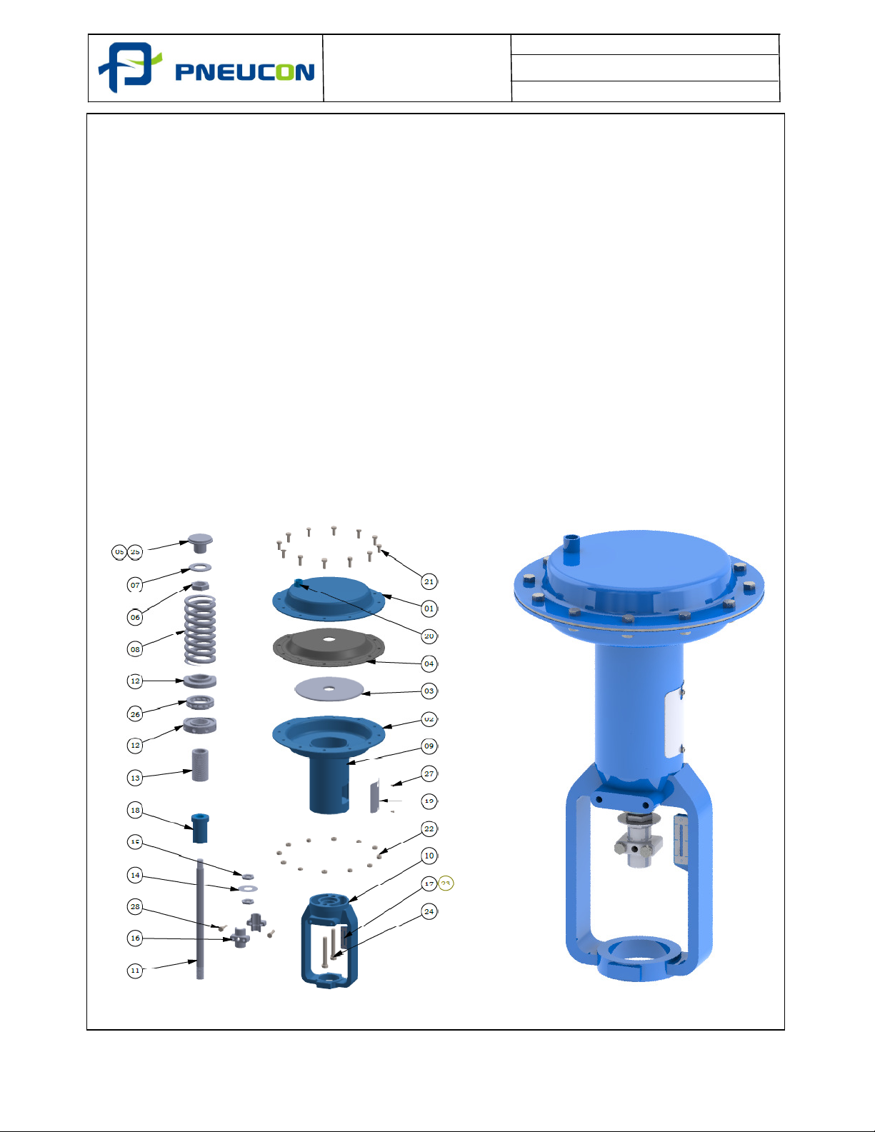
7.2 PDO Actuator Disassembly and Assembly
1. Open the Window Cover (Part No - 19).
2. Using the Spring Adjuster (Part No - 12) to release the Spring Compression (Part No -
08).
3. Remove the Casing Bolt and Nut (Part No - 21 & 22).
4. Remove the Top Casing (Part No - 01).
5. Remove the Hex Bolt from coupling (Part No - 28) and separate the coupling (Part No -
16).
6. Remove the Indicator lock nut (Part No - 16) and Travel indicator (Part No - 14) from
stem.
7. Unscrew the Diaphragm Collar Nut (Part No - 06) and Remove the Spring Guide (Part
No - 07) and Remove the Area Plate (Part No - 03).
8. Remove the Diaphragm from the actuator (Part No - 04).
9. Clean all the internal parts and examine for any damage. Any significantly damaged
parts should be replaced.
10. After replacing the diaphragm Re-assemble the actuator.
11. Using the spring adjuster (Part No - 12) to compress the spring (Part No - 08) until the
actuator start to operate at the bench set figure detailed on the nameplate.
06/19 20 of 23
Page 21
Document No. : PVIM/110/01
Revision No. : 00
Date. : 01.0
6
.2019
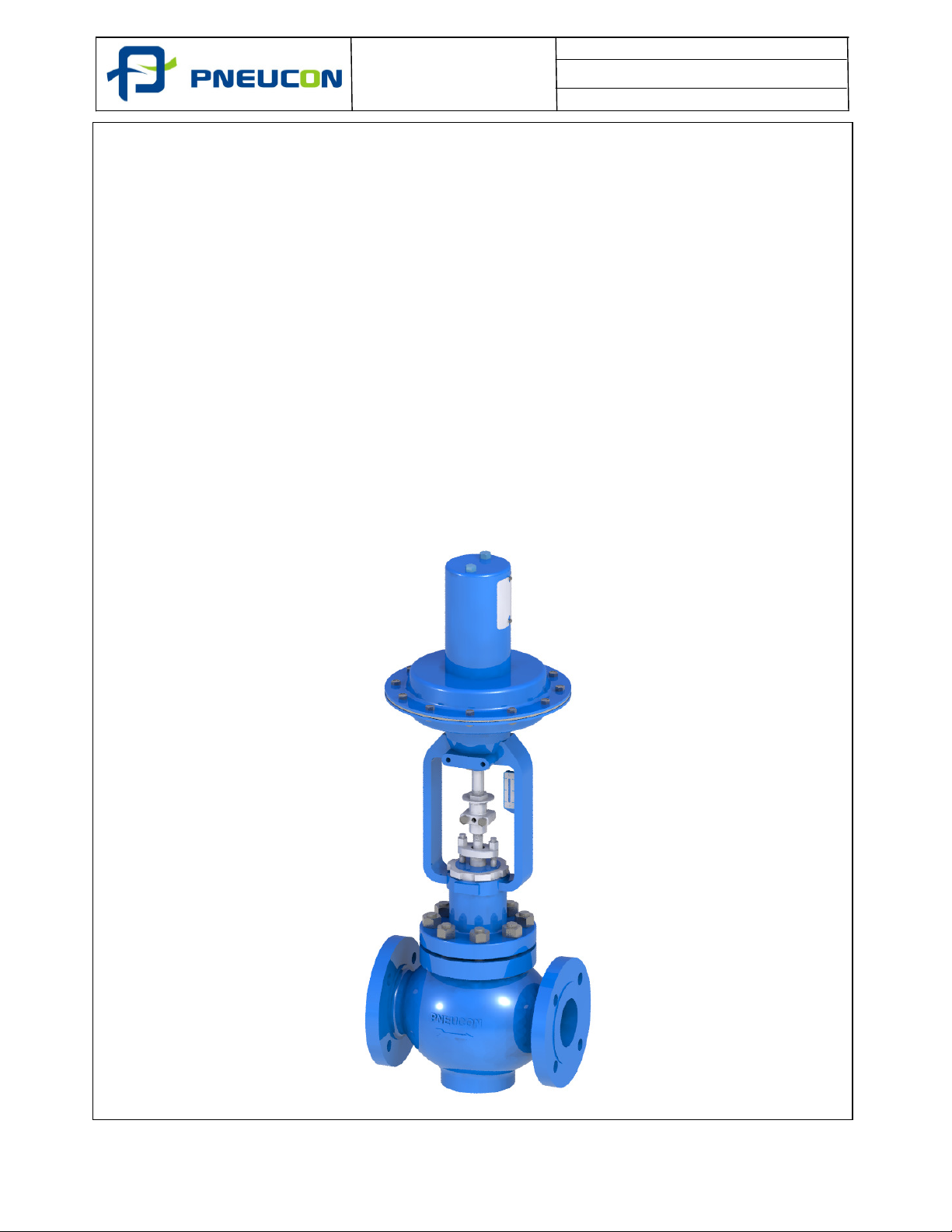
8 Actuator to Control Valve Assembly
8.1 Fitting Actuator to Valve
1. Ensure that the actuator is correctly assembled and calibrated.
2. Lower the actuator over the plug stem and gland flange to seat squarely on the
valve bonnet.
3. Rotate the actuator to the required position, screw the locking ring onto the
bonnet and securely tighten.
4. To connect the actuator to the valve stem the valve plug must be on its seat and
the actuator in the lowest travel position. Apply one half of the stem coupling to
both the valve and actuator stem. Apply the second half of the coupling carefully
engaging the threads, then insert the coupling cap screws and hand
tighten.Move the plug off the seat by changing the air pressure on the diaphragm
then unscrew the plug stem an additional turn out of the coupling to ensure
positive seating. Securely tighten the coupling cap screws.
5. Position the valve in the closed position and adjust the travel indicator plate so
that the ‘Shut’ mark is opposite the travel plate.
06/19 21 of 23
Page 22
Document No. : PVIM/110/01
Revision No. : 00
Date. : 01.0
6
.2019
8.2
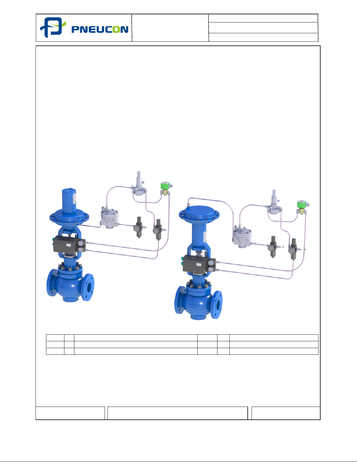
MOUNTING ACCESSORIES
VP - Valve Positioner
-
Pneumatic E/P & Smart
VB -
Volume Booster
FPR
-
Filter Pressure Regulator
QEV
-
Quick Exhaust Valve
SV - Solenoid Valve
AL -
Air Lock
Prepared by R.R.C
IF IN DOUBTS
- PLEASE ASK
Approved by J.N.C
1. Control valve assemblies generally comprise of a valve, actuator and instrumentation.
The instrumentation normally includes a positioner and airset but can also include
other accessories e.g. volume booster, solenoid valve, air lock, quick exhaust valve and
limit switches.
2. Each instrument fitted would have a separate operating and instruction manual and
this would be included in the data book. This would detail any specific requirements for
the instrument. For operator safety and reliability the following care should be taken.
3. Ensure that a suitable air filter is provided for the equipment in accordance with each
instrument.
4. The pneumatic supply pressure should not exceed the limits detailed for each of the
respective instruments.
General arrangement of accessories is shown in the schematic diagram. The
accessesories Shown in the dottedlined can be bypassed.
SCHEMATIC LINE DIAGRAM OF ACCESSORIES
06/19 22 of 23
Page 23
Document No. : PVIM/110/01
Revision No. : 00
Date. : 01.0
6
.2019
9.
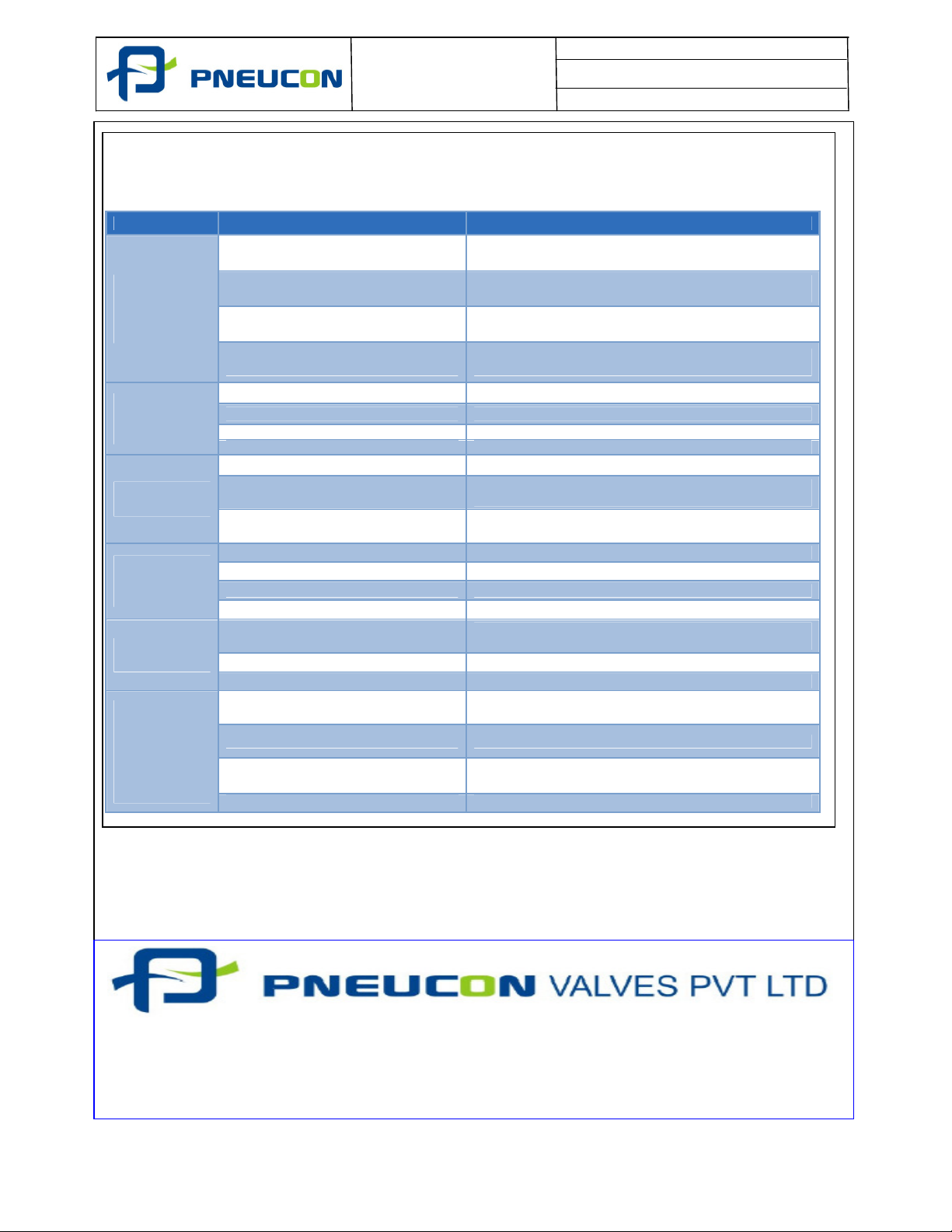
TROUBLESHOOTING
Alignment of valve
and actuator stem
Check actuator is square and tight on bonnet mounting
Actuator faulty
Service actuator as detailed in maintenance manual
Plot No: A
-
35, Road
No. 10,Wagle Industrial Estate,
Web: www. pneuconvalves.com
PVIM
-
110
Designed By : R.R.C
Control valve normally require seldom attendance, except for routine check on the control valve
response in respect of the input signals received from the controller. The following details some
of the problems associated with the control valve operation:
PROBLEMS REASON CORRECTIVE ACTION
Excessive
leakage
when valve
closed
Valve
operation
not smooth
Worn or damaged seat ring or plug
Inadequate actuator thrust
Actuator leakage
Improper handwheel adjustment (
acting as a limitstop )
Gland flange over tightened Loosen gland flange nuts and retighten to finger t ight
Inadequate air supply Check air supply pressure
Inadequate
flow
Control
valve
hunting
Excessive
noise
Valve travel
range less
than
correspondi
ng input
signal range
In order to avoid possible injury to personnel or damage to valve parts< WARNING and CAUTION notes must be
strictly adhered to. Modifying this product, substitution non-factory inferior parts, or using maintenance
procedure other than outlined could drastically affect performance, void product warranties and be hazardous to
personnel and equipment.
While ordering spares,please indicate `Valve Serial No.’appearing on Name Plate’fixed on the Actuator.
The Company’s policy is one of Continuous product improvement and the right is reserved to modify the
specifications contained here in Without notice
Improper plug adjustment Refer ‘Valve Assembly’ section of the manual
Malfunctioning valve positioner
Service conditions exceeds trim design
capacity
Input signal fluctuations Provide steady signal through controller
Backlash error in moving parts Remove backlash
Moisture in air line Provide dry air supply
Improper tuning of controller Adjust the controller settings
Flashing or cavitations
Loose supports Tighten the supports sufficiently
Damaged trim assembly Replace the trim parts
Malfunctioning valve positioner
Leakage through diaphragm chamber Tighten casing bolts and replace diaphragm if necessary
Excessive tightness of gland packing Loosen the gland packing slightly
Line pressure may have increased Compression spring should be readjusted
Disassemble and replace damaged part as detailed in
maintenance manual
Check actuator spring adjustment and air supply
Reconfirm service conditions and contact factory
Check for air leaks with soapy water. Tighten or replace
connection / seals.
Check travel against travel plate. Adjust handwheel to
neutral position
Bypass positioner and check valve operation with direct
signal
Reconfirm service conditions and contact factory
Check that trim is suitable for the application. Refer to
factory
Bypass positioner and check valve operation with direct
signal
Thane – 400 604, India.
Phone: +9122 2583 8371/72, Fax : +9122 2583 8373
E-Mail: [email protected]
06/19 23 of 23
 Loading...