

Page 1
TrimLine Vehicle Dock
For Panasonic CF33 Laptop Computers
User Guide
Description Part Number
TrimLine Dock for Panasonic CF33 Laptop, NPT AS7. P033.500
TrimLine Dock for Panasonic CF33 Laptop, DPT AS7. P033.502
TrimLine Dock for Panasonic CF33 Laptop, NPT w/ Screen Lock
Module
TrimLine Dock for Panasonic CF33 Laptop, DPT w/ Screen Lock
Module
TrimLine Cradle for Panasonic CF33 Laptop AS7. P033.504
TrimLine Cradle for Panasonic CF33 Laptop w/ Screen Lock Module AS7. P033.514
TrimLine Dock for Panasonic CF33 Laptop, DPT – Cap. Lock AS7.P033.522
CF33 Laptop Dock - Screen Lock Module AS7. P033.006
CF33 Laptop Dock - Screen Support AS7. P033.007
AS7. P033.510
AS7. P033.512
www.precisionmounts.com
call us at 1-888-869-7652 | [email protected]
Page 2

General Instructions
POWER:
• The power input should be 15.6Vdc / 7.05 A. The dock is meant to operate on 14.5 Vdc to 16
Vdc. Use a recommended power supply for the dock. Panasonic recommends using a Lind
Auto Adapter (Lind part no: PA 1580-1745) for this dock.
WIRING:
• PMT does not recommend relying on a cigarette socket adaptor for powering vehicle docks.
We recommend hard wiring using a good clean ground direct from the vehicle battery (-) post,
and (+) supply from a fused 12v location also directly from the vehicle battery. All Peripherals
connecting to the docking station should get power and ground from the same location as the
dock.
• Visit www.precisionmounts.com/support/installation-user-guides.html for a copy of our
general wiring and troubleshooting guide.
SERVICING [ENTRETIEN]:
• If the dock does not work as intended, please contact PMT for troubleshooting or to schedule
a service. [Si le dock ne fonctionne pas comme prévu, contactez PMT pour le dépannage ou
pour planifier un service.]
• Servicing of the dock should be only done by authorized service center personnel.
Unauthorized servicing of the dock will void its warranty. [L'entretien du dock ne doit être
effectué que par le personnel du centre de service autorisé. Un entretien non autorisé du dock
annulera sa garantie.]
EXTERNAL ANTENNA:
• For DPT (Dual Pass Thru) models, there is an option to turn off the external antenna. This
switch is located next to power port of the dock. Toggle the switch gently – excess force might
break the switch. Turning off the external antenna will let the computer use in-built antenna.
By default, the dock comes with the switch in ON position.
Page 3
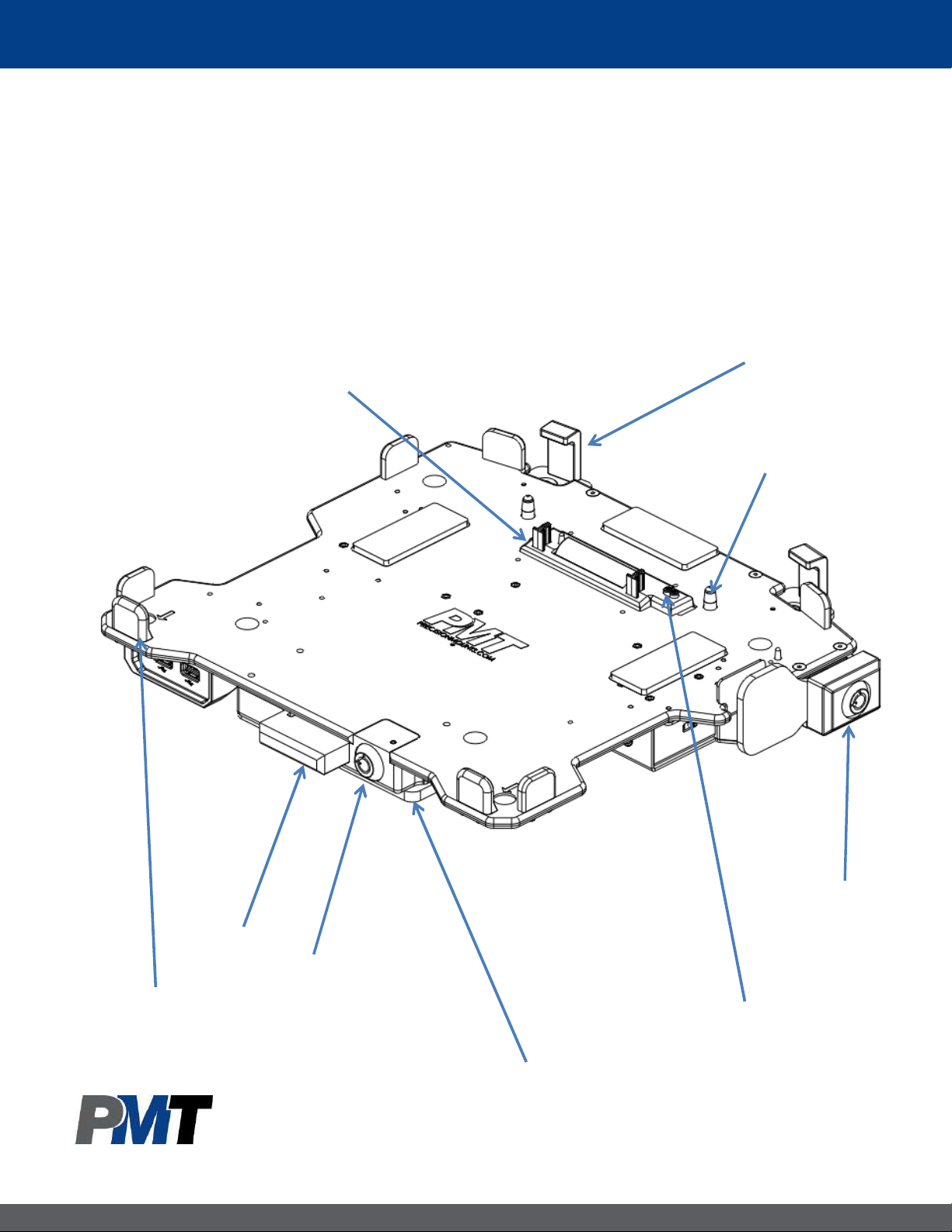
Description of Parts and Layout
Note: All pictures used in this guide are of Dual Pass Thru (DPT) with Screen Lock Module (Part no:
AS7.P033.512). However processes and information relate to other variants of the same dock
mentioned in previous page.
Front View
Docking Connector Housing
with Shutter Cover
Back Hook (X2)
Guide Pins
Latch
Front Clamps (X2)
Screen Lock
Module
Lock
RF pass thru
connectors
Mounting Plate
Page 4
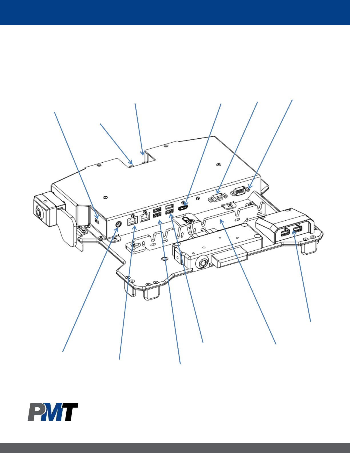
Description of Parts Continued
Rear View (without mounting plate)
External Antenna
Switch
EXT ANT 1
EXT ANT 2
HDMI
VGA
Serial
Power
15.6 Vdc IN
Ethernet (X2)
USB 2.0 (X2)
USB 3.0 (X2)
USB 2.0 (X2)
Cable
Management Bar
Page 5
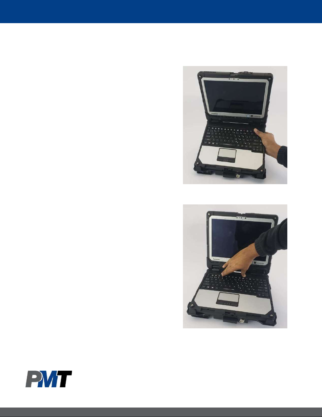
Docking the Laptop
Step 1:
Ensure that the dock is unlocked and
unlatched. If locked, insert key and rotate lock
90 degrees counter-clockwise. If latched, push
the latch inside such that the back hooks move
all the way out.
Step 2:
Lead the front of the keyboard into the dock
such that the pockets on keyboard line up with
the front hooks. The side tabs should help
aligning the laptop as well.
Step 3:
Push gently in the back center of the keyboard
so that back hook latches. A click sound should
be heard when the back hook latches.
*The laptop can be docked into the dock with
lid open or close. If the lid is open, make sure
that no keys are pressed while docking.
Step 4:
[Additional security] Rotate key 90 degrees
clockwise and remove the key to lock the
laptop in the docking station. The tablet is only
fully secure once the key is removed.
Page 6
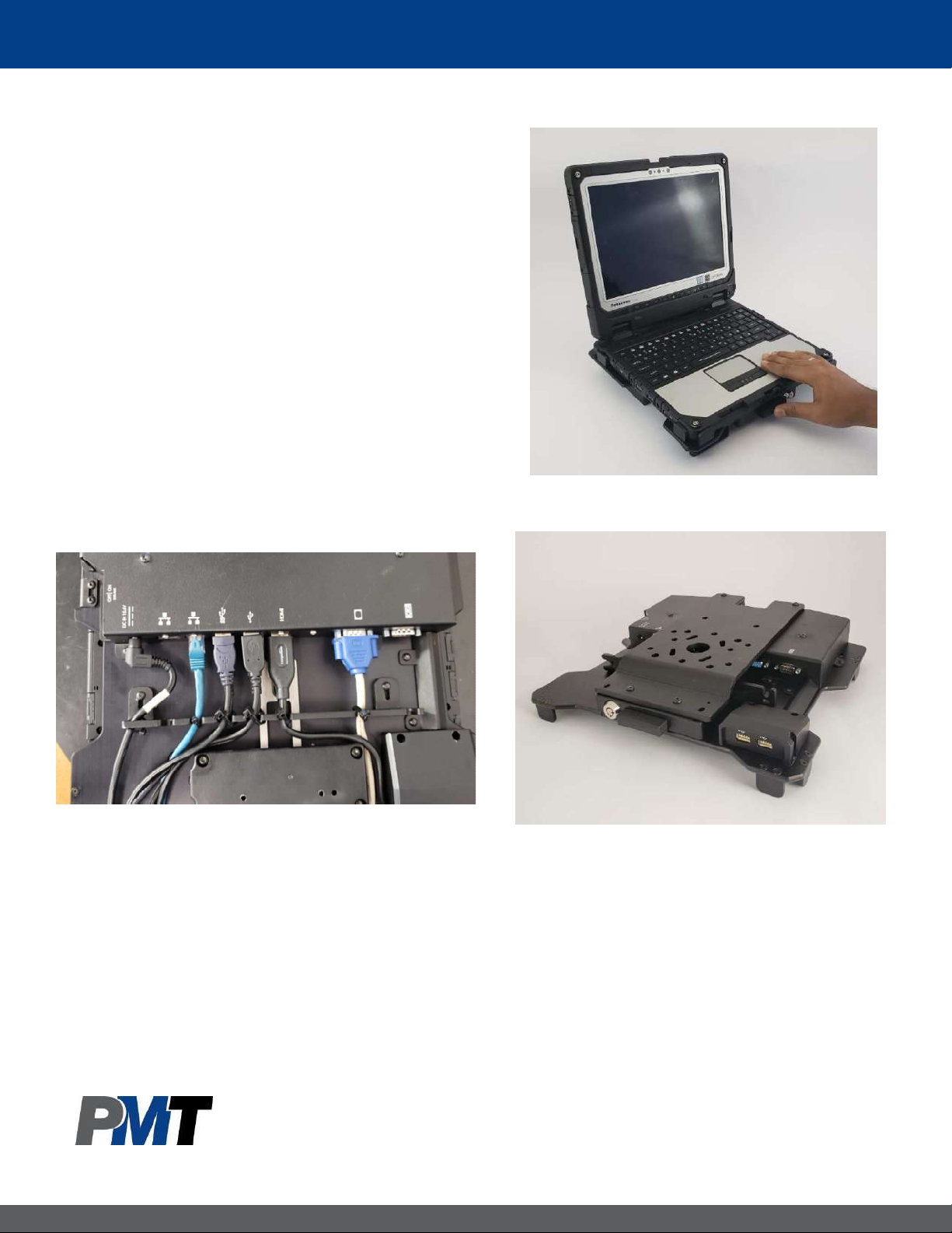
Undocking the Laptop
Step 1:
Ensure that the dock is unlocked. If locked,
insert key and rotate lock 90 degrees
counter-clockwise.
Step 2:
Use your thumb to push the latch in the
front. This will push the back clamp out and
the laptop will eject with a small click sound.
Once the laptop ejects, gently pull the
laptop out of the dock
Cable Management & Mounting
Connect all cables securely to dock ports,
and use tie straps to secure cables to the
“Cable Management Bar” as shown.
The cable tie bar has slots, so if needed,
the location can be adjusted slightly.
The standard mounting bracket that comes
with the vehicle dock features an industry
standard VESA 75mm x 75mm bolt pattern.
This allows easy mounting to many preexisting mounts as well as dedicated mounts
from PMT. Use the supplied #¼-20 hardware
for attaching it to the mount.
Attach the mounting bracket to the dock
using the 4 supplied #10-24 UNC screws as
shown above (after attaching the mounting
plate to PMT mount)
Page 7
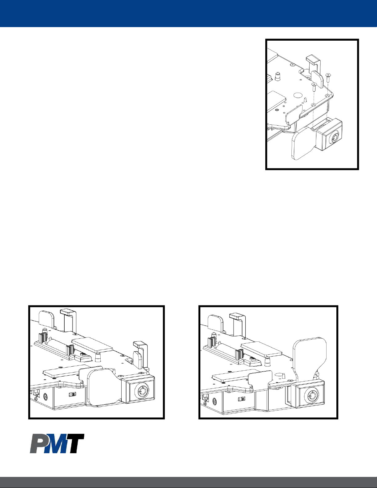
Screen Lock Module
Screen Lock Module prevents theft deterrence of the tablet
from the laptop while it is in the dock. Screen Lock module is
not included in all the kits. It comes attached to the dock if it
is included in the kit.
A Screen Lock module could be purchased separately and
installed later. If the Screen Lock was purchased separately,
attach it to the passenger side of the dock using the #6-32
hardware provided (as shown aside).
Below images show the Screen Lock Module in unlocked (arm is horizontal) and locked
(arm is vertical) position.
Once the laptop is docked and locked, activate the screen lock module by inserting the
key in the lock and rotating it 90 degrees in clock wise direction. This would rotate the
arm by 90 degrees and block the tablet lock/unlock button on the keyboard tray.
The laptop can be docked/undocked from the dock irrespective of Screen Lock Module
position. If needed the Screen Lock Module can be left always in locked position.
The Screen Lock Module can be locked/unlocked with the same key of the dock
Page 8
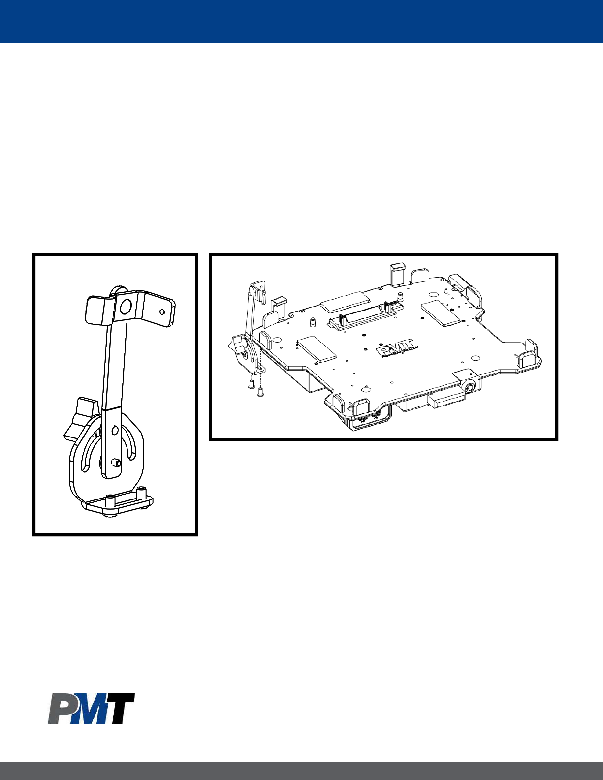
Screen Support
Screen Support provides additional support to the screen and reduce the screen rattle
during dock usage. Screen Support is not included in any dock kits. It could be
purchased separately and installed.
Attach it to the driver side of the dock using the #6-32 hardware provided (as shown
below). The clearance between the screen support arm and the screen could be
adjusted due to the mounting slots. Loosen the #6-32 (X2) screws and adjust the
placement of the screen support.
 Loading...