

Page 1
1
GOLD 1-3 SK-GB -708
Right to make modifications without prior notice
:
:: :
Commissioning, operation,
and maintenance: GOLD 1-3
1. INTRODUCTION ............................................................ 1
2. ELECTRICAL CONNECTION ........................................ 4
3. CONNECTION OF EXTERNAL FUNCTIONS ............... 5
4. WIRING DIAGRAM POWER CARD .............................. 6
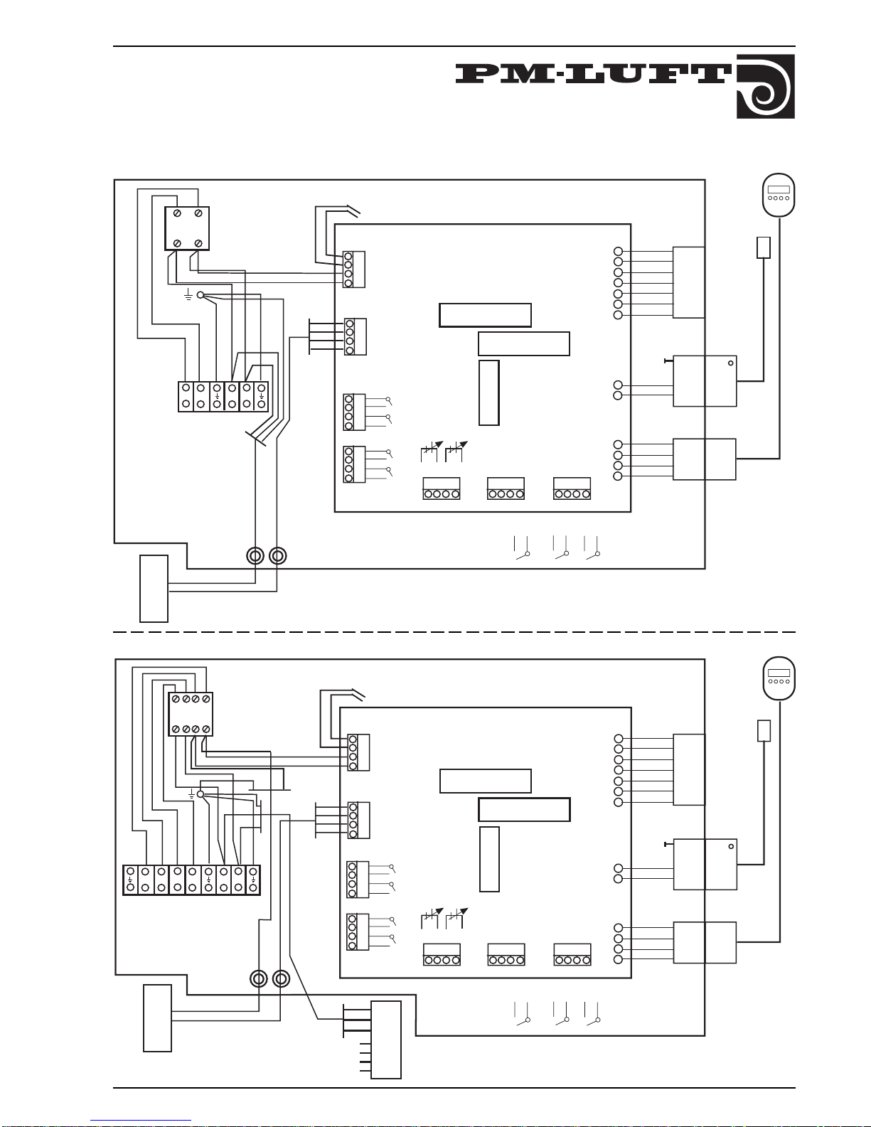
5. WIRING DIAGRAM CONTROL CARD .......................... 7
6. STARTING-UP ............................................................... 8
7. ADJUSTMENTS ............................................................. 9
8. FUNCTIONS ................................................................. 13
9. ADJUSTMENT PROTOCOLE...................................... 18
10. ALARM .........................................................................19
11. MAINTENANCE ............................................................ 21
TELEPHONE NUMBERS PM-LUFT ............................22
INDEX
1. INTRODUCTION
1.1 GENERAL
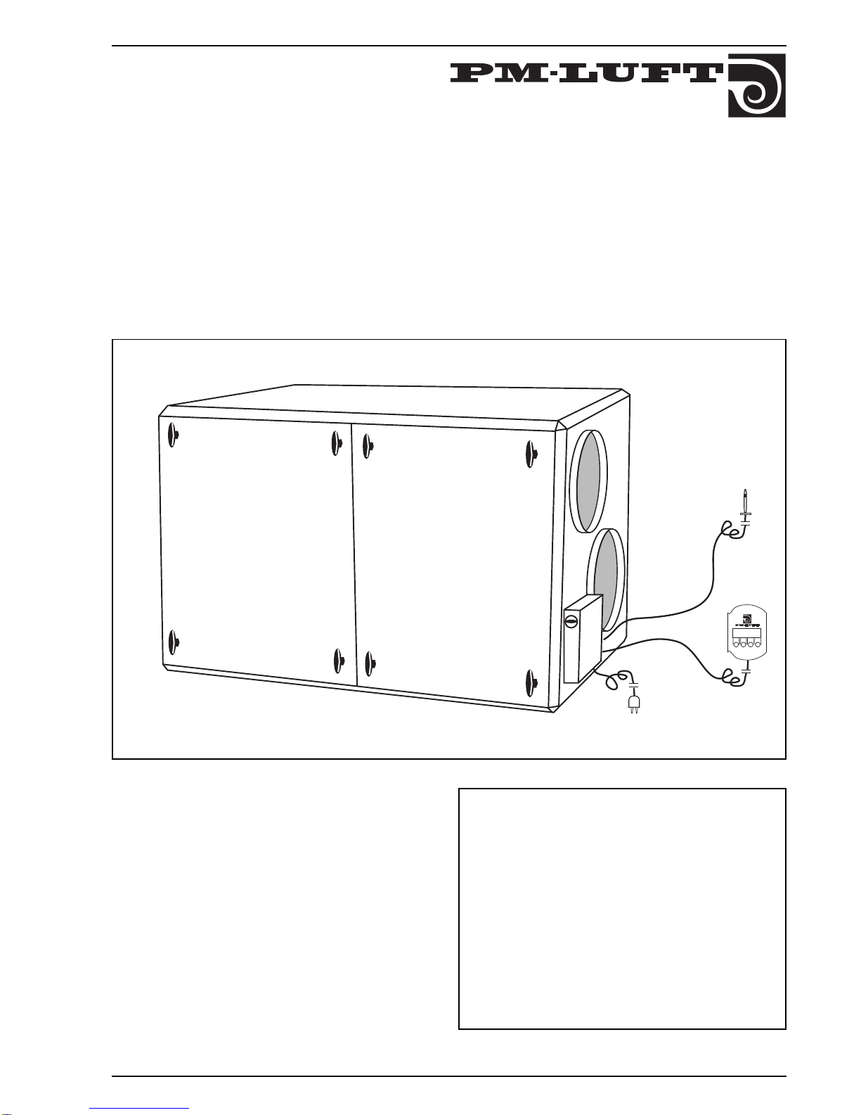
GOLD is a complete air handling unit, with built-in control
system, developed and manufactured by PM-LUFT AB.
The unit contains supply and exhaust air fans, rotary heat
exchanger Turbo, supply and exhaust air filters F85/EU7
and control system.
These instructions are for the commissioning, operation,
and maintenance of the unit. It is important that they are
read by all personnel involved before the unit is put into
service. Please see separate instructions for installation
WARNING!
Inspection hatches located on the pressure side behind
the fan must not be opened while the fan is operating. The
hatch can open suddenly and cause personal injury.
Page 2

2
GOLD 1-3 SK-GB-708
Right to make modifications without prior notice
1.2 SPECIFICATION
When contacting PM-LUFT, please use manufacture
number, program version (see 7.3), and description as
given below:
Silencer GODA-1-aaa
Size 025, 031, 040
Round, Size 016-040
Silencer GODB-1-aaa
Size 010, 012, 016, 020
Outdoor Air Hood
(Incl. ceiling vent assembly) GOHA-1-a
Exhaust Air Hood GOHB-1-a
(Incl. ceiling vent assembly)
Size 1, 2, 3
Combi Hood GOHC-1-a
(Incl. ceiling vent assembly)
Outer Wall Hood GOHE-1-a
Outer Wall Grille GOHF-1-a
Size 1, 2, 3
Smoke Function Box GOQA-1-01
Incl. Control Unit ABAV
Smoke Detector VS 1130 GOQA-1-02
Damper Adjuster SQ B 21.1 GOQA-1-03
EXTRA ACCESSORIES
Stand GOLZ-1-a-02
Size 1, 2, 3
Motion Detector GOLZ-1-03
Extension Cable GOLZ-1-05-a
Type 5 m with bayonet coupling
to manoeuvre display, 4 pole =1
5 m with bayonet coupling
to battery, 7 pole =2
Transformer 12 VDC GOLZ-1-06
For supply to motion detector
Set of Hinges GOLZ-1-a-07
Delivered unassembled
Cannot be used with the GOLZ stand
Size 1, 2, 3
Replacement Material
Filter F85/EU7, 1 pc. GOLZ-1-a-01
Size 1, 2, 3
Air Handling System GOLD-a-b-cc
Type
Size 1 =2
2, 3 =3
Size 1, 2, 3
Display Language SWE - ENG =01
SWE - FIN =02
POL - ENG =03
TJECK - TY =04
FRA - ENG =05
EST - ENG =06
COMPLEMENTS
Damper and motor GOSA-1-aaa-b
Tightness Class 4
Round size 016, 020, 025, 031, 040
Damper motor with spring return =1
On/Off =2
Adjustment Damper (Round) GOSB-1-aaa
Size 010, 012, 016, 020, 025, 031, 040
Water Heat Radiator GOLA-1-a
Incl. 2-way valve, adjuster, anti-freeze protection,
and connection cable with bayonet coupling.
Size 1, 2, 3
Anti-freeze sensor GOLZ-1-04
Electric Heat Radiator GOLE-1-a-b
Incl. integrated thyristor and connection
cable with bayonet coupling.
Size 1, 2, 3
Voltage 400V =1
230V =2
Water Cooling Radiator GOKx-1-a-b-c-d
Cooling Agent Water =A
Evaporative =C
Size 1, 2, 3
Duct Connection Ø 250 = 1
Dimension Ø 315 = 2
Ø 400 = 3
Ø 500 = 4
No. of Tube Rows 4, 6
Connection Side Right =1
Left =2
Page 3
3
GOLD 1-3 SK-GB -708
Right to make modifications without prior notice
:
:: :
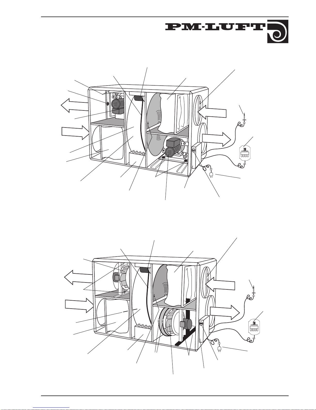
Drive belt
heat exchanger
Locking knob
flex. conn.
Drive motor
heat exchanger
Supply air filter
Heat exchanger
Exhaust air filter
Plug contact
Throttle damper
Exhaust air fan
OUTDOOR
EXHAUST
SUPPLY
Locking
knobs fan
Supply air fan
Exhaust air
sensor
EXTRACT
Power card
Control enclosure
with control card
Main-/safetyswitch
Locking
knobs fan
:
:: :
Drive Motor, Heat
Exchanger
Supply Air Filter
Heat Exchanger
Exhaust Air Filter
Throttle Damper
Exhaust Air
Sensor
Main/Safety Breaker
Clamp Belt
Outdoor Air
Sensor
SUPPLY
Supply Air Fan
Drive Belt, Heat
Exchanger
EXHAUST
Electric Plug
(Size 2)
Locking
Knobs, Fan
Assembly
Control Box
with Controller
Card
Power Card
EXTRACT
OUTDOOR
GOLD size 1
GOLD 2 and 3
Outdoor air
sensor
Locking Knobs,
Fan Assembly
Exhaust Air Fan
Supply air sensor
(to be placed in
supply air duct)
Display
Supply air sensor
(to be placed in
supply air duct)
Display
Page 4
4
GOLD 1-3 SK-GB-708
Right to make modifications without prior notice
2. ELECTRICAL CONNECTION
2.1 Power
Units in sizes 1 and 2 are connected with factory installed
electrical plug, otherwise permanently connected to
single phase 230V, 50Hz, 10A.
For size 3 permanent connection applies, 2 x 230 V + N,
50 Hz, 2 x 10 A.
2.2 Safety
Lockable isolator switch is located on the control enclosure.
2.3 Display
The display is connected to the unit via contact on the
factory mounted cable on the display.
2.4 Supply air sensor
The sensor is fixed into the supply air duct at a distance
of at least 5 x the duct diameter from the unit or possible
reheater. Shall always be mounted after coil.
2.5 Reheater
2.5.1 Electrical heater
Power supply shall be carried out through working switch
directly from distribution box.
Unit size 1 2,0 kW, 2-phase 400 v + earth, 5,0 A.
Unit size 2 3,6 kW, 2-phase 400 V + earth, 9,0 A.
Unit size 3 6,0 kW, 3-phase 400 V + earth, 8,7 A.
Control signal to the built-in thyristor is connected to the
unit via a quick coupling on the factory mounted cable on
the electrical heater.
Alarm from the overheating protection is transferred to
the unit and shown on the display.
Possible reset of alarm is done on the battery and the
display.
At stopped unit cooling is carried out when necessary.
2.5.2 Watercoil
The control signal to the valve + actuator is connected to
the unit via a quick coupling on the pre-connected cable
to the actuator.
Page 5
5
GOLD 1-3 SK-GB -708
Right to make modifications without prior notice
3. CONNECTION OF EXTERNAL FUNCTIONS
3.1 General
Cables from external functions are connected to
connection boxes on the control card.
Knockout openings for screw caps are located in the
control enclosure.
Functions:
External stop of unit (external disconnection)
External Fire/Smoke (external disconnection)
External alteration High/Low speed
(external connection/disconnection)
Set value shifting (external 0 – 10 VDC)
Flow indication FL/alt. stepless controlling of
cooling unit (output 0 – 10 VDC)
Flow indication TL (output 0 – 10 VDC)
Summary alarm A (free making contact)
Summary alarm B (free making contact)
Controlling of cooling unit on/off (free
making contact
Unit in operation (free making contact)
3.2 External stop
If the connection between connections 1–2 is broken the
unit is unconditionally stopped. "Stop" is shown in the
display. The unit is started when the connection closes.
Clamp is factory mounted.
3.3 External Fire/Smoke
If the connection between connections 3–4 is cut the unit
is unconditionally stopped and the alarm text "External
Fire alarm released" is shown in the display. Alarm light
and summary alarm relay A-alarm are activated. The error
must be repaired and the alarm reset on the display
before starting. Clamp is factory mounted.
3.4 External alteration Low/high speed
On connection 5–6 device for alteration between low and
high speed can be connected. It might be presence
sensor, overtime timer, overtime pushbutton, air quality
sensor, hygrostat or other potential free contact function.
Use the display to choose if high speed is required with
closed or broken contact. Delay of resetting to low speed
after contact alteration is programmed with the display,
0.00–3.59 in hours and minutes.
The internal high speed of the time switch is placed
above external contact function. If for instance presence
sensor is used the internal time switch shall be programmed to low speed all the time.
3.5 External set value displacement
Connections 7(-) and 8(+) is input for 0–10 VDC for
displacement of set value. Upon regulation of supply/
exhaust air, the set value for supply/exhaust air
temperature is displaced. Upon regulation of ERS, the
difference between EA/SA is displaced.
The function is activated in the display. The influence is
+/- 5°C according to 8.4.
3.6 Flow indication Supply–Exhaust air
On connections 9(+) and 10(-) there is a output voltage of
0 –10 VDC which is proportional to measured supply air
flow. Connections 11(+) and 12(-) contains 0 – 10 VDC for
exhaust air flow.
3.7 Summary alarm outputs
Connections 13–14 summary alarm B free making
contact (10 A), closed at alarm.
Connections 15–16 summary alarm A free making
contact (10 A), closed at alarm.
3.8 Cooling unit
3.8.1 On/off control
Connections 17–18 free making contact (10 A) for ON/
OFF controlling of possible cooling. The function is
activated in the display.
When need for cooling the contact closes. A neutral zone
of 2°C is programmed. When the need for cooling stops
a restart time of 10 minutes starts, which must end
before the contact can close again. This time delay is to
prevent the unit from starting and stopping too often.
3.8.2 Stepless control
Controlling can also be carried out stepless, depending of
the need of cooling via 10 VDC. Connections 11(+) and
12(-), which normally are for indication of exhaust air
flow, is then used. Due to this, indication of exhaust air
flow can not be obtained.
When using the valve adjuster, 24V supply must be
taken from an external source.
3.9 Operation indication
Connection 19–20 free making contact(10 A). The
contact is closed when the unit is in operation (low/high
speed). The contact is broken when unit is stopped,
regardless to if it has been stopped manually, via clock or
alarm.
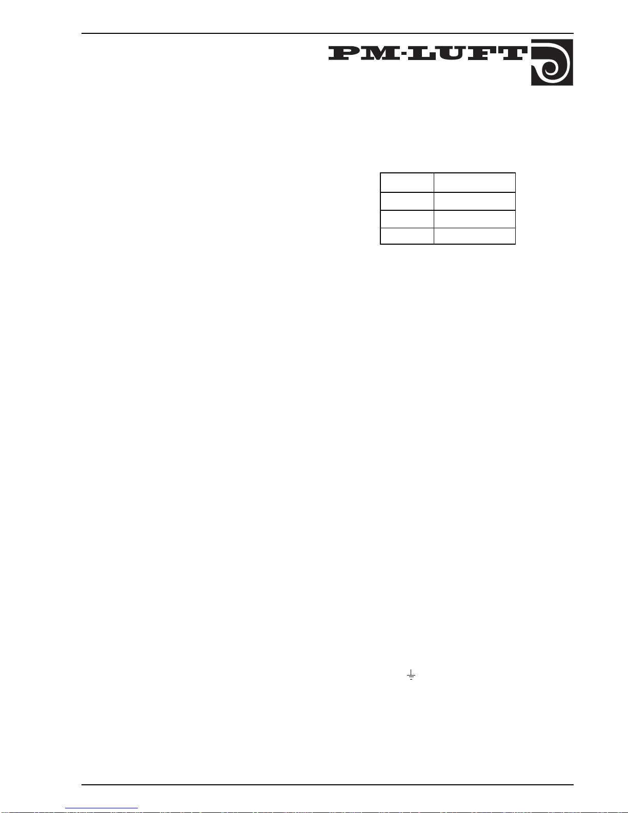
3.10 UTG 230 V
Connections L, , N marked with UTG 230 V is a
connection with 230 VAC supply, which is cut off with the
main switch.
The socket lays on the supply fuse and therefore the
maximum load is depending on how hard the unit is
driven.
The outlet is recommended for use for control voltage or
for damper motors.
Size 0–10 VDC
1 0–320 l/s
2 0–500 l/s
3 0–900 l/s
Page 6
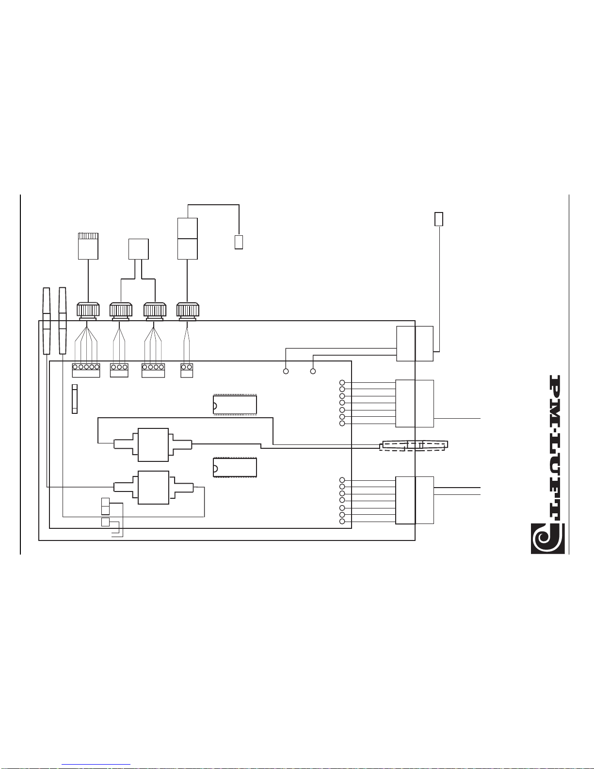
6
GOLD 1-3 SK-GB-708
Right to make modifications without prior notice
1
5432
1
32
1
4
32
1
2
PRESSURE
SENSOR
SA–FLÄKT
PRESSURE
SENSOR
EA–FLÄKT
*GOLD* POWER CARD
3
4
1
2
3
4
SUPPLY AND
CONTROLLING
SUPPLY AIR FAN
5
6
7
1
2
3
4
5
6
7
SUPPLY AND
CONTROL FROM
CONTROL CARD
OUTDOOR AIR SENSOR
EXHAUST AIR
FAN SUPPLY
AND CONTROL
HEAT EXCH
MOTOR
EXHAUST AIR SENSOR
+
-
Black
Brown
Black
Yell/Green
Blue
Brown
Yell/Grey
Blue
Brown
White
Green
Yellow
White
Brown
Blue
Brown
Black
Yell/Green
Blue
Brown
White
Yellow
Green
1
2
Black
Yell/Green
Blue
Brown
White
Yellow
Green
GOLD POWER
+
-
+
-
+
-
GOLD-PRESSURE
FUSE
1 A
folio
4. WIRING DIAGRAM POWER CARD
Page 7
7
GOLD 1-3 SK-GB -708
Right to make modifications without prior notice
Size 1 and 2
Size 3
5. WIRING DIAGRAM CONTROL CARD
*GOLD* CONTROL CARD
CONNECTION
POSSIBLE
HEATER
SUPPLY AIR
SENSOR
-
+
-
+
DC-OUTPUT
FL TL
HIGH
LOW
FIRE
INPUT
STOP
UNIT
DISPLAY
COMMUNICATION
DISPLAY
ALARM
OUTP. A
ALARM
OUTP. B
-
+
SUPPLY AND COMMUNICATION POWER CARD
MAIN
SWITCH
N
Black
Red
Blue
Brown
White
Yellow
Green
1
7
6
5
4
3
2
Blue
Brown 4
3
Pin
2
1
Green
Yellow 2
1
White
Brown 4
3
1112 910 78563412
24
21
22
23
20
17
18
19
16
13
14
15
L
27 28
UNIT IN
OPER.
COOL.
UNIT
230 V
INPUT
GOLD-CPU
GOLD-PROG
GOLD-CONTROL
QUICK COUPLING
Brown
Blue
Yell/Green
Blue
Brown
Yellow
Green
Blue
Brown
Brown
White
24
21
22
23
20
17
18
19
16
13
14
15
L1
27 28
2 x 230 V INPUT
L2N1 N2
Brown
Yell/G
Blue
Supply
SA fan
Black
Blue
Blue
Brown
Brown
Yellow
Green
Blue
Blue
Brown
Blue
Brown
White
Brown
Blue
Yell/Green
Yell/Green
-
+
-
+
-
+
1
7
6
5
4
3
2
4
3
2
1
2
1
4
3
GOLD-CPU
GOLD-PROG
GOLD-CONTROL
1112 910 78563412
Yell/Green
Yell/Green
*GOLD* CONTROL CARD
DC-OUTPUT
FL TL
DC-IN
SET VALUE
DISPL.
HIGH
LOW
FIRE
INPUT
STOP
UNIT
MAIN
SWITCH
Black
Red
Blue
Brown
White
Yellow
Green
Blue
Brown
Pin
Green
Yellow
White
Brown
ALARM
OUTP. A
ALARM
OUTP. B
SUPPLY AND COMMUNICATION POWER CARD
UNIT IN
OPER.
COOL.
UNIT
QUICK COUPLING
CONNECTION
POSSIBLE
HEATER
SUPPLY AIR
SENSOR
DISPLAY
COMMUNICATION
DISPLAY
Folio
Black
Black
Brown
Blue
Yell/Green
Folio
Black
Black
Brown
DC-IN
SET VALUE
DISPL.
28
25
26
27
28
25
26
27
Page 8
8
GOLD 1-3 SK-GB-708
Right to make modifications without prior notice
::::
::::
::::
::::
1 = SVENSKA
2 = ENGLISH
12 OK
*GOLD* DAY 1 – 10:15
STOP
MAN AUTO S-CL PROG
*GOLD* DAY 1 – 10:15
HIGH SPEED
MANUAL OPER
AUTO STOP S-CL H-LS
MAN STOP S-CL PROG
*GOLD* DAY 1 – 10:15
AUTO OPER
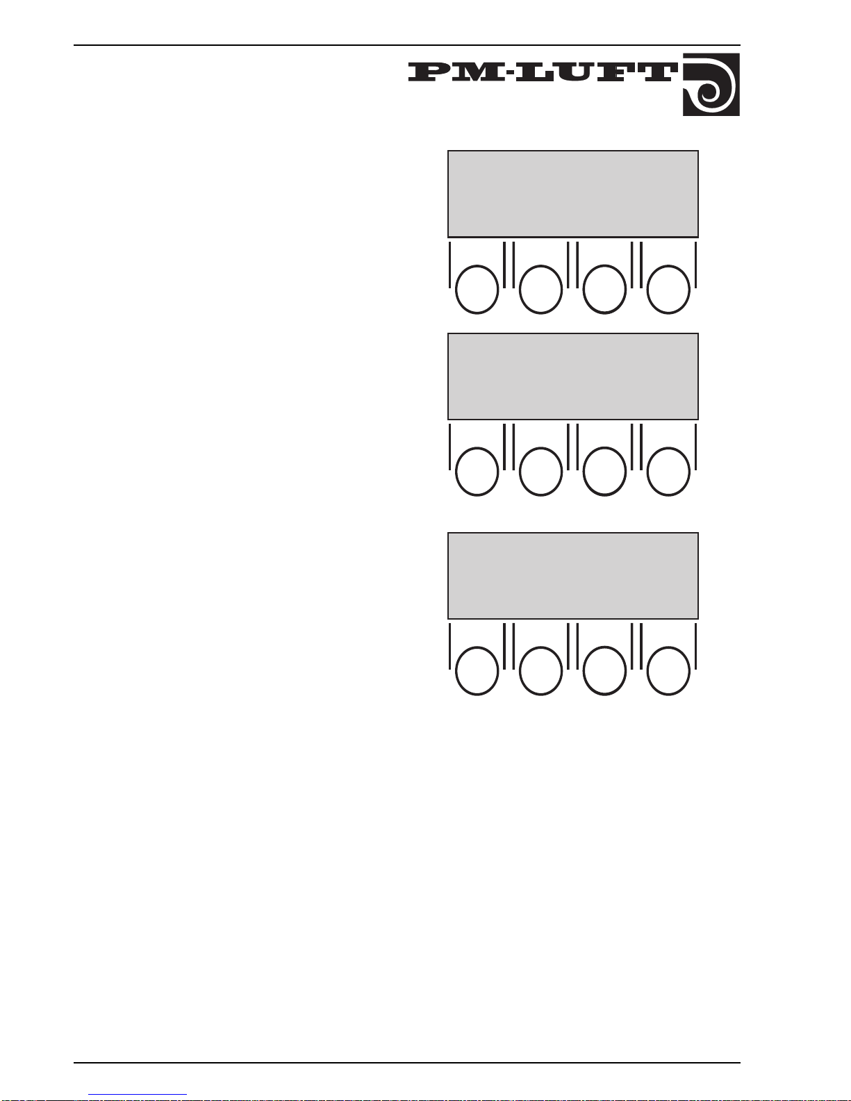
6. STARTING-UP
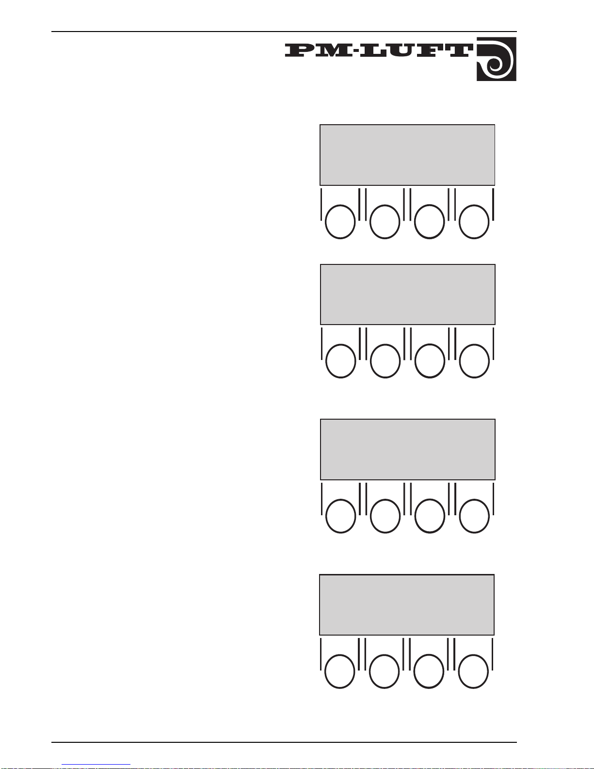
When the unit is connected and the main switch is
connected for the first time, a language selection menu
is shown on the display.
Choose desired language by pushing the button for
respective number.
When desired language flashes push "OK".
The picture in the display changes.
The third line gives operation type choosen, "STOP",
"AUTO OPER", or "MANUAL OPER".
In this case STOP is shown.
Normally the unit shall operate in "AUTO OPER" (which is
shown in the next sketch), since the switching clock
handles alteration from High to Low speed.
The second line shows which operating mode is
current: HIGH SPEED, LOW SPEED, or STOP. If any
other function is affecting the flow, it flashes on the
second line alternately with current mode, e.g., FILTER
TEST, SUMMER NIGHT COOL, ZERO SET CALIBR.,
ROTARY GUARD TEST, RECOOLING, or COOL
RECOVERY.
At "MANUAL OPER" button "H–LS is used in order to alter
between manual high speed or manual low speed.
In "MANUAL OPER" there is no automatic switch
between high and low speed via switching clock.
External high speed is superior to Manual low speed.
Page 9
9
GOLD 1-3 SK-GB -708
Right to make modifications without prior notice
7. ADJUSTMENTS
7.1 General
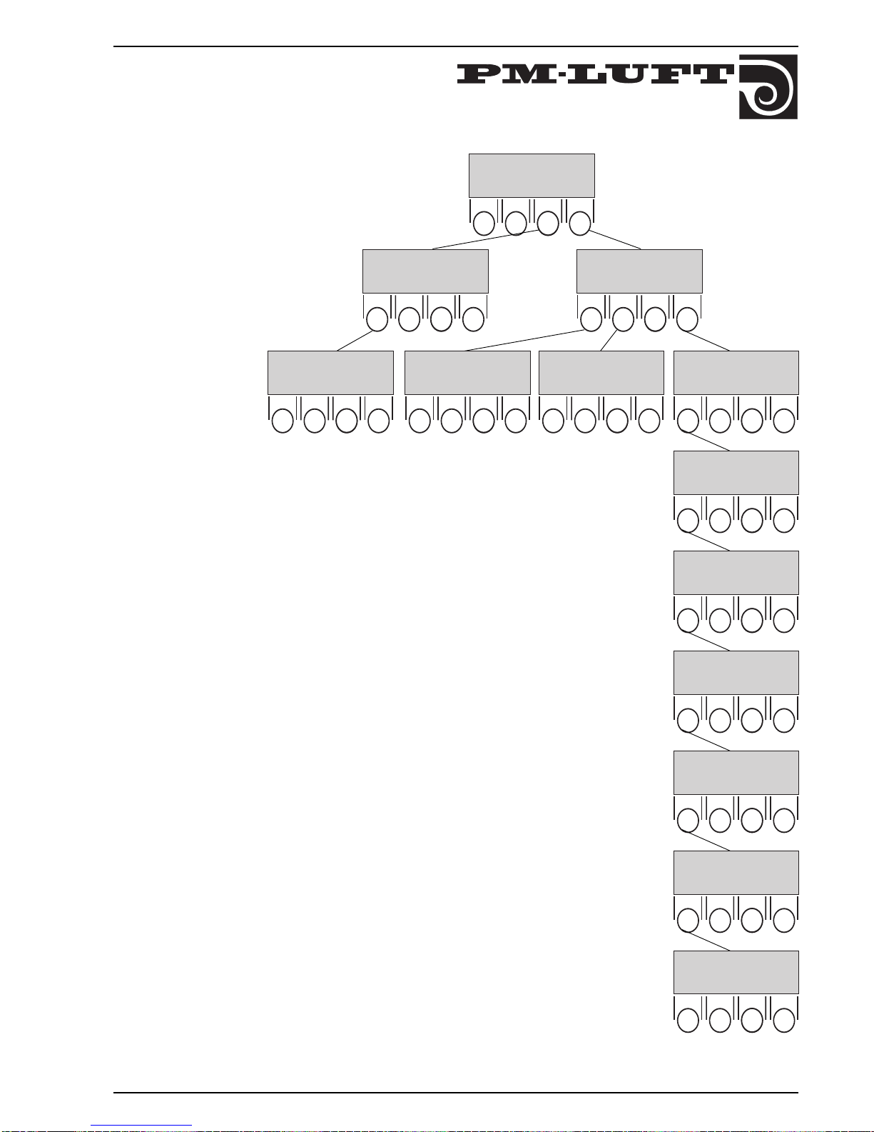
Push the buttons, according to sketch, until you reach
the group you want to read off or alter.
The functions of the buttons within the group are as
follows:
Turn forward between pictures in the
group.
Turn backwards between pictures in the
group.
RET Return to previous level.
PROG Alter to shown picture altering mode.
+ Step up the value for the flashing
numbers.
- Step down the value for the flashing
numbers.
SET Step forward so that new numbers
flashes. After the last numbers, alter back to
read off mode.
See also 9. Adjustment protocole!
➜
➜
::::
::::
::::
➜
➜
:::: ::::
➜
➜
::::
::::
HIGH SPEED 00.00–00.00
DAY 1
NO 1
➜
➜
RET PROG
::::
COOLING UNIT 0
DUCT CALIBR 0
SERV PERIOD 12 MONTHS
RET PROG
➜
➜
::::
➜
➜
::::
ANTI FR GUARD FUNC 0
RET PROG
➜
➜
::::
SUPP AIR FILTER
FILTER STATUS NOW 01
ALARM LIMIT 10
RET PROG
➜
➜
::::
RET PROG
➜
➜
::::
1 = SVENSKA
2 = ENGLISH
RET PROG
➜
➜
MAN STOP S-CL PROG
*GOLD* DAY 1 – 10:15
HIGH SPEED
AUTO OPER
ACTUAL TIME
DAY 1 – 10:15
RET PROG
*GOLD* DAY 1 – 10:15
PV 02:2 : OPER 0250D
SETTING
TEMP FLOW RET FUNC
ERS-REG STEP 2
OFF/ON-DIFF 3
°C
BREAKPOINT 22
°C
RET PROG RET PROG
HIGH SPEED:: LOW SPEED
700 l/s SA 400 l/s
700 l/s EA 400 l/s
SUMMER NIGHT COOL 0
OUTD A TEMP COMP 0
SET VALUE DISPL 0
RET PROG
RET PROG
EXT HS TIME DELAY 0:00
CLOSURE=HIGH SPEED
TIME FILTER TEST 22.59
EXH AIR FILTER
FILTER STATUS NOW 01
ALARM LIMIT 10
Page 10
10
GOLD 1-3 SK-GB-708
Right to make modifications without prior notice
Then program desired times for High speed operation.
DAY on second line can be chosen 0, 1, 2, 3, 4 , 5, 6, 7,
1–5, 1–7.
Day 0 means that set times do not have any influence.
Day 1.....7 are days of week, where Day 1 = monday.
Day 1–5 means that set times applies for monday–friday.
Day 1–7 means that set times applies for the whole
week.
NO 1 shows which of the 12 programming pictures that
is shown.
Totally 12 different variants are possible to program. No
1–12 on the third line gives which one of the 12 variants
shown at the given time.
In certain cases two variants can be necessary, i e if high
speed over a 24 hour joint is required. First from required
time to 23.59, then new variant from 0.00 to required
time. The unit will then operate at high speed during the
programmed times.
7.2 Switching clock
First programme the right day and time.
Then programme desired times for High speed operation.
::::
*GOLD* DAY 1 10:15
PV 02:2 : OPER 0250D
SETTING
TEMP FLOW RET FUNC
::::
ACTUAL TIME
DAY 1 10:15
RET PROG
➜
➜
::::
HIGH SPEED 7:15 – 16:30
DAY 1
NO 1
RET PROG
➜
➜
The upper line gives actual time,
"PV – xx" gives the version of the micro processor
programme. Should always be given when contacting
PM-LUFT about program.
"OPER" gives the the total operation time of the unit in
days. Time for low speed and high speed are included.
7.3 Programming menue
Page 11
11
GOLD 1-3 SK-GB -708
Right to make modifications without prior notice
::::
ERS-REG STEP 2
OFF/ON-DIFF 3 °C
BREAK POINT 22 °C
RET PROG
10
16
15
14
13
12
11
22
21
20
19
18
17
10
161514131211 222120191817 23 27262524
Temperature supply air °C
Step 1
Step 2
Step 3
Temperature exhaust air °C
Difference
Break point
::::
SUPPLY AIR REG
SUPPLY AIR TEMP 21 °C
RET PROG
::::
EXHAUST AIR REG
EXHAUST AIR TEMP 21 °C
SA MIN/MAX 15/40°C
RET PROG
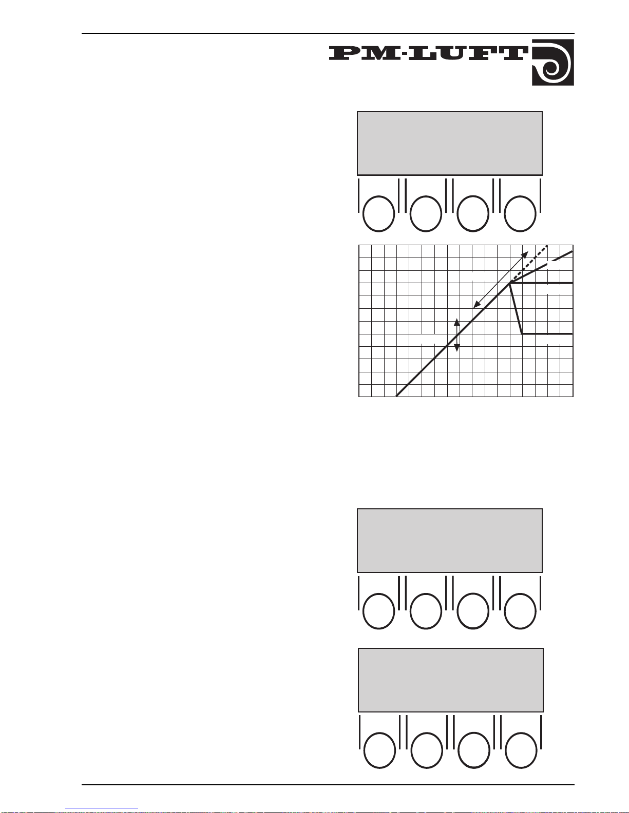
7.4 Temperatures
7.4.1 ERS regulation
Exhaust air temperature Related Supply air regulation
(ERS). This means that the supply air temperature is
regulated in relation to the exhaust air temperature.
GOLD is intended mainly for this type of regulation.
Choose step 1, 2 or 3 according to diagram to the right.
OFF/ON–DIFF is the difference which the supply air
temperature shall be below the exhaust air temperature
below the break point in the diagram to the right. The
diagram is drawn for 3°C DIFF.
The BREAK POINT is the point in the diagram from where
the steps starts. It is defined from the exhaust air
temperature. In the diagram, the breakpoint is 22°C.
7.4.2 Other regulation types
Change of regulation form to EXHAUST AIR
REGULATION or SUPPLY AIR REGULATION is carried
out in alteration mode where button three steps around
between the regulation forms, "EA - R", "SA - R", and "ERS
- R".
When PROG is pushed, the different values will flash.
They are then possible to alter with button 1 and 2, which
then shows + or - in the display.
7.4.2.1 Exhaust air regulation
EXHAUST AIR TEMP is the desired temperature in the
exhaust air duct.
SA – MIN is the lowest temperature and SA – MAX is the
highest temperature allowed for supply air when the
regulation tries to keep exhaust air constant.
7.4.2.2 Supply air regulation
SUPPLY AIR – TEMP is the desired temperature in the
supply air duct.
Page 12
12
GOLD 1-3 SK-GB-708
Right to make modifications without prior notice
Closed Opened
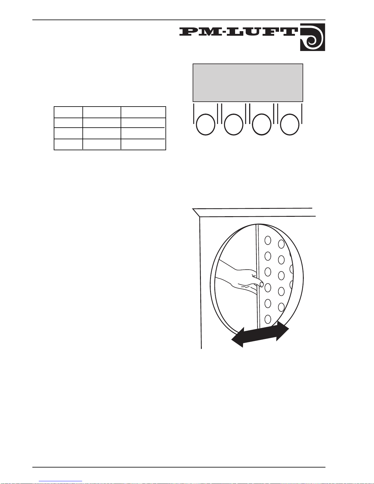
7.6. Throttle damper
Before the throttle damper is adjusted, duct calibration
shall be carried out, see 8.6.
The damper shall be fullyopened, pushed so that no part
is in the the exhaust air inlet (see sketch).
Set the supply and exhaust air flows on the display
(according to 7.5 above).
After that, make an adjustment which distributes the
total supply and exhaust air flow so that each diffusor
obtains the correct flow.
There after it is time to adjust the pressure balance in the
unit with the help of the damper so that the purging flow
goes to the exhaust air side.
On the external electrical enclosure there are two red
pressure nipples for measuring the negative pressure on
the supply and exhaust air side. At the nipples there are
a + for the pressure on the supply air side and a - for the
pressure on the exhaust air side.
Connect the manometer or other pressure meter to the
connections for + and - and measure both pressures.
NOTE! With both nipples negative pressures are
measured.
If the negative pressure on the exhaust air side is at least
as high as on supply air, the adjustment is ready.
If not, remove the inspection door, adjust the damper
slightly, put back the inspection door and measure the
pressures. Repeat until the negative pressure on the
exhaust air side is at least as high as on supply air side (0–
20 Pa).
New duct calibration should be done when the damper
has been adjusted.
WARNING!
Inspection hatches located on the pressure side behind
the fan must not be opened when the fan is operating.
The hatch can open suddenly and cause personal
injury.
Min flow l/s
Max flow l/s
Size
7.5. Flows
Where the flows are programmed in l/s and the smallest
step is10 l/s.
Min and max flows:
GOLD 1 70 320
2 110 500
3 230 900
Low speed flow can also be set to 0, which stops the unit
at times for low speed on the switching clock.
Programmed flows is automatically kept in GOLD.
::::
HIGH SPEED :: LOW SPEED
700 l/s SA 400 l/s
700 l/s EA 400 l/s
RET PROG
Page 13
13
GOLD 1-3 SK-GB -708
Right to make modifications without prior notice
8. FUNCTIONS
8.1 General
Following functions can be altered in the display.
Summer night cooling (0/1)
Outdoor air temp compensation (0/1)
Set value displacement (0/1)
Cooling unit on/off (0/1)
Cooling unit 0–10 VDC
Duct calibration (0/1)
Service period (0–9999 months)
Ext high speed time delay (0–3.59 h)
External closure (High speed/low speed
Time filter test (00.00–22.59)
Anti-freeze guard (0/1)
Supply air filter alarm limit (0–100)
Exhaust air filter alarmlimit (0–100)
Language selection (SVENSKA, ENGLISH)
Other functions:
Cooling recovery function, Purging function, Recooling, Zero
calibration
3
2
1
6
5
4
-20 +100-10 +40+30+20
Outdoor air temperature °C
Set value displacement°C
Wintercompensation
Summer-
compensation
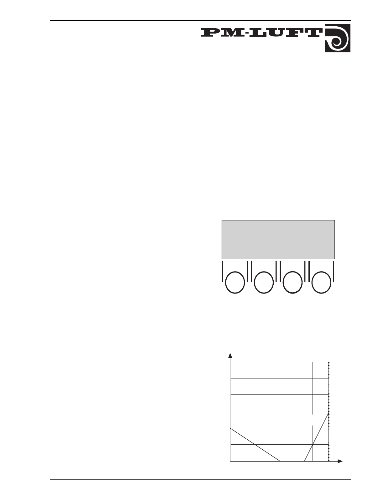
8.3 Outdoor air temperature compensation
If the function is = 1 (on), the temperature set value is
displaced relative to the outdoor air temperature. The set
value displaced is the supply air temperature at supply air
regulation and exhaust air temperature at exhaust air
regulation. The temperature set value is increased if the
outdoor air temperature drops below +10°C according to
winter compensation curve or raises above 25°C according
to summer compensation curve. See diagram to the right.
::::
➜
➜
SUMMER NIGHT COOL 0
OUTD AIR TEMP COMP 0
SET VALUE DISPL 0
RET PROG
8.2 Summer night cooling
At summer night cooling = 1 (on) the unit is operating on high
speed with a supply air of 10°C from 23.10 until the exhaust
air temperature is lowered.
Conditions which must be satisfied before the summer
night cooling function will start (at 23:10 hours):
– The exhaust air temperature should be above the preset
value (+24°C).
– The outdoor air temperature must be above the preset
value (+10 °C).
– The need for heating must have not existed between
12:00 and 23:00 hours.
– The unit must not run at high speed or be shut down by
means of pressing the manual stop button on the control
display or external stop.
Conditions which must be satisfied before the
summer night cooling function will stop:
– The exhaust air temperature must fall below the preset
value (+16 °C).
– The outdoor temperature must fall below the preset
value (10 °C).
– The timer or external input must call for high-speed
operation.
– The buttons on the control display will be influenced.
Page 14
14
GOLD 1-3 SK-GB-708
Right to make modifications without prior notice
0
5
10
0
-4
-2
+2
+4
+5
Set value displacement °C
Control signal V DC
::::
COOLING UNIT 0
DUCT CALIBR 0
SERV PERIOD 12 MONTHS
RET PROG
➜
➜
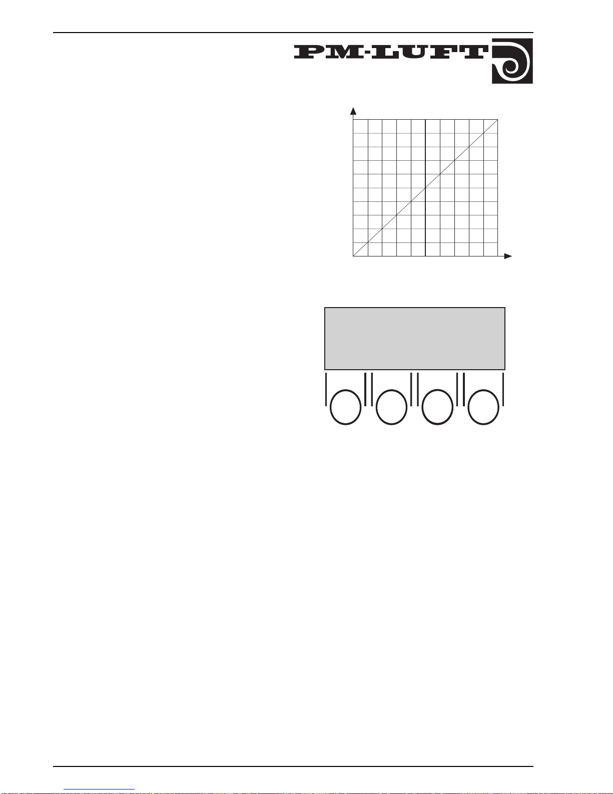
8.4 Set value displacement
At SET VALUE DISPL = 1 (on). The temperature set value
can be displaced +/- 5°C with the help of 0–10 VDC
external control.
The set value displaced is the EA/SA-differance at ERSregulation, the supply air temperature at supply air
regulation and the exhaust air temperature at exhaust air
regulation.
When activating the function the set value is displaced
according to diagram to the right. 0 VDC gives a decrease
of the temperature set value of 5°C, 5VDC gives
unchanged set value and 10 VDC gives an increase of
5°C. Upon ERS regulation, the EA/SA difference decreases when there is an increased control signal. EA/SADIFF cannot be less than 1° C.
The external control signal is connected on the
connection box 7–8 (-)(+) of the control card.
8.5 Cooling unit
8.5.1 Cooling on/off
At COOLING UNIT = 1 (on).
When need of cooling occurs a closure of free making
contact is obtained (connection box 17–18). This closure
can be used to start an external cooling unit.
When the need of cooling stops the contact opens and a
restart time of 10 minutes starts running. This is to
prevent too many start/stops of the cooling unit
A neutral zone of 2°C is programmed so that set value at
cooling is 2°C higher than set value.
Conditions for activation of cooling function.
Exhaust Air regulation:
- Exhaust air temperature rises above the set value
including the neutral zone.
- Supply air temperature is above the set value on
SA-MIN.
ERS Regulation, Step 3:
- Supply air temperature rises above the set value
according to the set curve including the neutral
zone.
Conditions for interrupting the cooling function:
Exhaust Air regulation:
- Exhaust air temperature has gone down to 0.5
degrees above the set value.
- Supply air temperature is below the set value on
SA-MIN.
ERS Regulation, Step 3:
- Supply air temperature has gone done to 0.5
degrees above the set value according to the set
curve.
The function is not applicable upon Supply Air
regulation and ERS Regulation, Steps 1 and 2.
Page 15

15
GOLD 1-3 SK-GB -708
Right to make modifications without prior notice
8.5.2 Stepless Regulation of Cooling
At COOL AGGREGATE = 2, a control signal of 0 - 10V
DC is maintained on plinth 11 (+) and 12 (-) for
regulation of stepless cooling. (See 3.8.2)
A neutral zone of 2° C. is allowed, as above.
When cooling is needed, the control signal is regulated
steplessly so that the set value increases while the
neutral zone is maintained.
SA-MIN maintains temperature limits for Supply Air
upon Exhaust Air regulation.
A closed contact between plinths 17 and 18 is also
maintained with this function when cooling is needed
and the temperature rises above the set value
including the neutral zone.
When the temperature has gone down to 0.5 degrees
above the set value, the contact opens and a restart
time of 10 minutes begins to run.
The contact also opens when SA-MIN goes below the
set value upon Exhaust Air regulation.
8.6 Duct calibration
At DUCT CALIBR = 1 (on).
The unit is operating on a firm calibration flow and
measures where in the flow diagram the unit is operating
with care taken to connected duct system and with clean
filters.
Duct calibration shall always be carried out when
alterations in the duct system have been carried out.
Set the duct calibration to 1 and go to "main menu" Auto
oper or Manual oper.
Duct calibration is carried out and 1 automatically
changes to 0 when the unit has stored the calibration
value and returned to normal operation (after appr. 5 min).
8.7 Service period
Shows how many months remaining until service period
alarm is released. The programming is carried out in
months.
Resetting of alarm is carried out via programming SERV
PERIOD to the next service interval.
Page 16
16
GOLD 1-3 SK-GB-708
Right to make modifications without prior notice
::::
RET PROG
::::
➜
➜
RET PROG
EXT HS TIME DELAY 1:15
CLOSURE = HIGH SPEED
TIME FILTER TEST 22:59
➜
➜
::::
SUPP AIR FILTER
FILTER STATUS NOW 01
ALARM LIMIT 10
➜
➜
RET PROG
EXH AIR FILTER
FILTER STATUS NOW 01
ALARM LIMIT 10
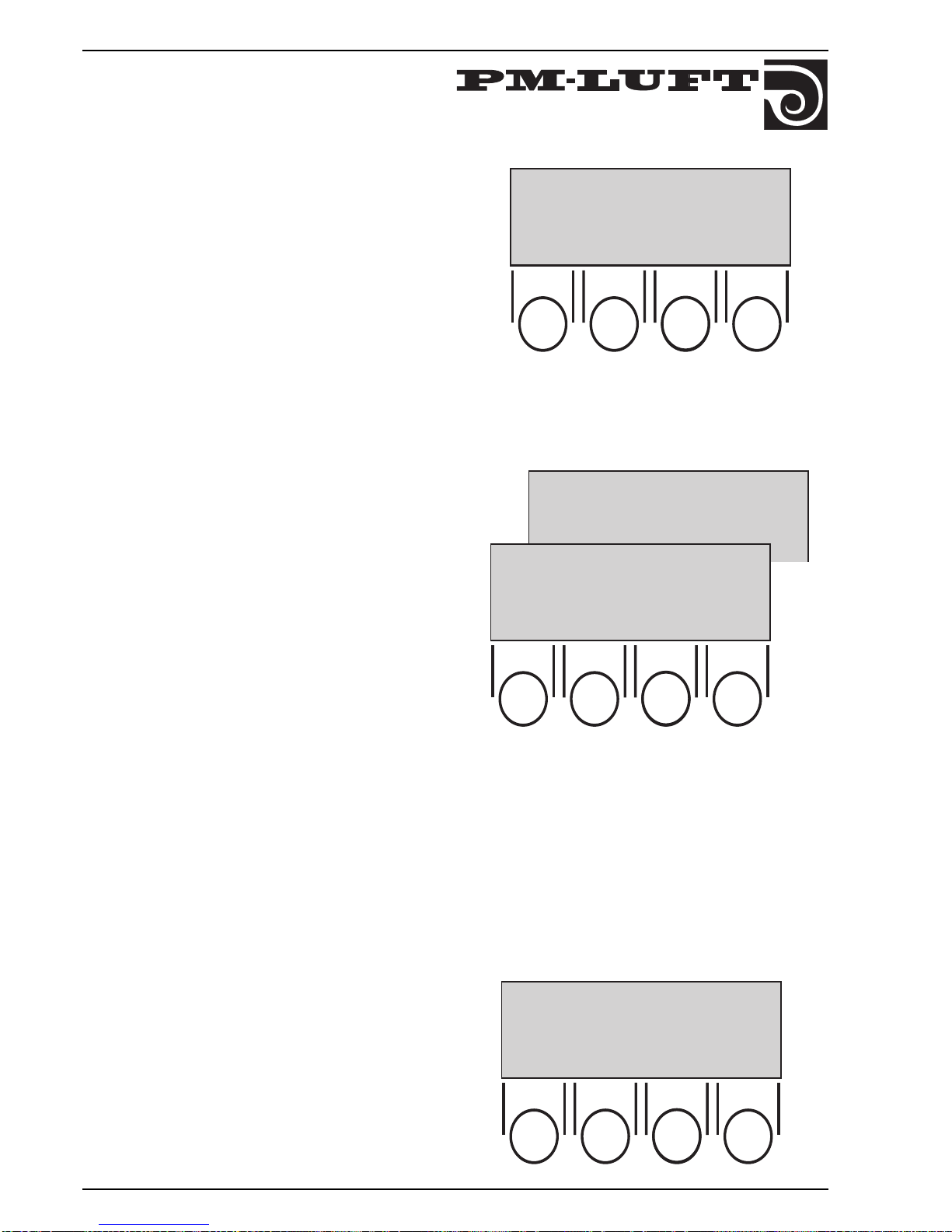
8.8 External high speed (time delay)
The function gives time delayed reset to low speed when
the input for external alteration between High speed and
Low speed shifts.
The time can be set 0:00 – 3:59 which is the time in hours
and minutes. 0:00 gives that the function is not activated.
Use: for instance prolonged operation with button or reoperation time together with presence sensor.
8.9 Closure = High speed or Low speed
Here can be chosen if the external alteration HS/LS shall
give High speed or Low speed at closed contact. Closure
= Low speed shall be chosen at i e presence sensor. If the
contact is not used "Closure = High speed" shall be
chosen (factory set).
The external contact only influences when the internal
switching clock calls for Low speed.
8.10 Time filter test
Set the start time for filter test (0.00–22.59). It shall be set
on the time when the least inconvenience for the user is
at hand, as the unit both is stopped and operates on filter
test flow regardless to what flow is chosen. Factory set
value is 22.59.
While External Stop is activated, no filter tests are
done. The filter test can be done if the aggregate is
running at low or high speed. Low speed can be set to
0 l/s, i.e. shut-off but still active. The filter test cannot
be done on a manually stopped aggregate.
8.11 Filter test
At filter test, the unit is operated up to filter test flow and
one of the pictures to the right is shown. The flow is
stabilized after ca 1 minute.
FILTER STATUS NOW shows the degree of pollutions for
each filter and ALARM LIMIT shows what level of
pollutions that provides a filter alarm. 10 units
corresponds to recommended final pressure drop across
the filter.
The limit can be set between 0 and 99. The factory set
value is 10. This causes the rpm of the fan to increase
approx. 5% from clean filter until alarm is shown.
8.12 Anti-freeze guard function
When water coil with anti freeze guard function is
connected it is determined if the anti freeze guard
function with heating of the water coil shall be activated
or not (activated = 1). The function is keeping coil warm
to 12°C at operation and to 25°C at stopped unit.
If the function is chosen and no sensor is connected, an
alarm is obtained.
::::
ANTI FR GUARD FUNC 0
RET PROG
➜
➜
Page 17
17
GOLD 1-3 SK-GB -708
Right to make modifications without prior notice
Cooling recovery function
The heat exchanger is driven on max speed to recover the
relative cold in the room when the outdoor air
temperature is higher than the exhaust air temperature.
Conditions for starting:
– No need of heating
– The outdoor air temperature is higher than the exhaust
air temperature
Conditions for stopping:
– The unit calls for heating
–The outdoor air temperature drops below the exhaust air
temperature
The text "COOL RECOVERY" flashes on the second line
on the display.
Purging function
The unit is operating but there is no need of heating and
the rotor does not operate.
After ca 3,5 hours the rotor is started during 1 minute on
max for purging.
Recooling
If the reheater has been operating, the coil is cooled off on
min. flow during 3 minutes, despite if Stop has been
ordered.
The text "RECOOLING" flashes on the second line on the
display.
Zero calibration
Every time the fans are stopped, the regulation controls
that the zero values of the pressure sensors are correct.
When the value is incorrect and the regulation carries out
a new calibration, the text "ZERO CALIBRATION" flashes
in the display. The fans are unable to start during this
time.
::::
RET PROG
➜
➜
1 = SVENSKA
2 = ENGLISH
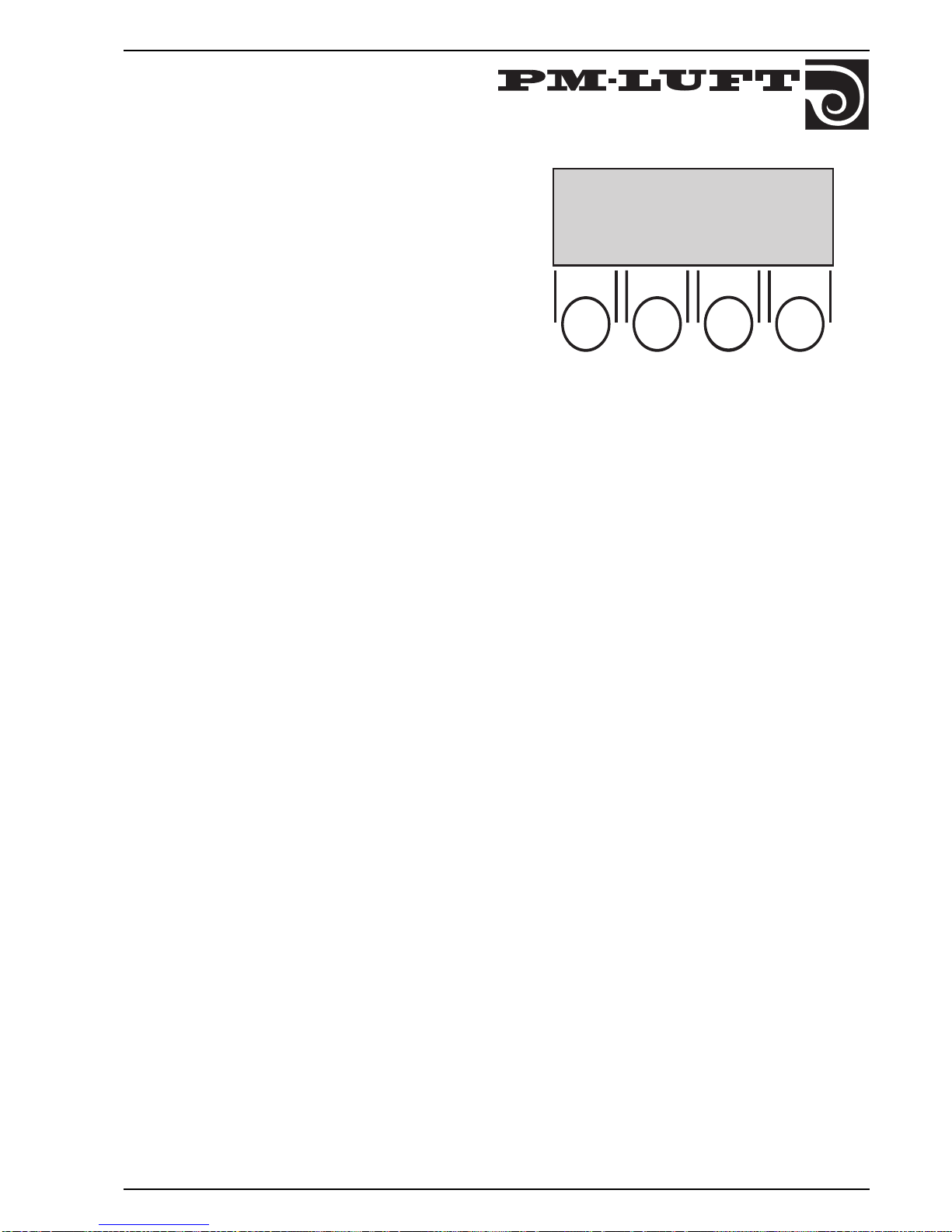
8.13 Language selection
The language can be altered between SVENSKA and
ENGLISH at any time.
The alteration is carried out when return to "main menu"
is done.
Page 18
18
GOLD 1-3 SK-GB-708
Right to make modifications without prior notice
9. Adjustment protocole
Function Factory set Projected Adjusted
value value value
Temperature Regulation function FRT ......................................
Set value, °C — ......................................
Min temp, °C — ......................................
Diff temp, °C 3,0 ......................................
Step 2 ......................................
Break point, °C 22,0 ......................................
Flow High speed supply air, l/s 200, 400, 700 * ......................................
Low speed supply air, l/s 100, 200, 400 * ......................................
High speed exhaust air, l/s 200, 400, 700 * ......................................
Low speed exhaust air, l/s 100, 200, 400 * ......................................
*) The three values is for ................................................
size 1, 2 respective 3.
Functions Summer night cooling 0 ......................................
Outdoor air temp. compensation 0 ......................................
Set value displcement 0 ......................................
Cooling unit on/off, Stepless 0-10V 0 ......................................
......................................
Duct calibration carried out — ......................................
Service period, months 12 ......................................
Ext high speed/low speed input
switch off delay, hours:min 0:00 ......................................
closure = high speed/low speed high speed ......................................
Time for filter test 22:59 ......................................
Anti freeze guard function 0 ......................................
(When having water coil.
Demands anti freeze guard sensor.)
Alarm limit filter guard
Supply air filter, units 10
**
......................................
Exhaust air filter, units 10 ** ......................................
**) Corr. to rec. final pressure
Times for high speed
No 1 ............ – .............. DAY ........
No 2 ............ – .............. DAY ........
No 3 ............ – .............. DAY ........
No 4 ............ – .............. DAY ........
No 5 ............ – .............. DAY ........
No 6 ............ – .............. DAY ........
No 7 ............ – .............. DAY ........
No 8 ............ – .............. DAY ........
No 9 ............ – .............. DAY ........
No 10 .......... – .............. DAY ........
No 11 .......... – .............. DAY ........
No 12 .......... – .............. DAY ........
Switching clock, actual time set Program version.............................
Page 19

19
GOLD 1-3 SK-GB -708
Right to make modifications without prior notice
::::
*** ALARM 1 ***
SUPP AIR MOTOR RELEASED
RES
10. ALARM
Alarm is given in plain text in the display and a red
zone below the buttons on the display.
All alarm texts are described below. Cause and some
check points are given. If the error still remains,
contact PM-LUFT . The alarms are not activated in
programming menues.
Resetting of alarm:
– Manual reset means, if not anything else is said,
that the button RES on the display is pushed.
– Automatical reset means that the alarm is reset
when the error is repaired.
*** ALARM 8 ***
"TEMPERATURE BELOW ALARM LIMIT"
A-alarm, the unit stopped.
The exhaust air temperature has been below the alarm
limit (factory set 15°C).
The alarm has a delay period of 20 minutes.
Manual reset on display.
*** ALARM 9 ***
"TEMPERATURE BELOW SET VALUE"
A-alarm, the unit has stopped.
The supply air temperature has diverged (factory set 5°C)
too much from the set value.
The alarm has a delay period of 20 minutes.
Manual reset on display.
*** ALARM 10 ***
"COMMUNICATION TO POWER CARD
BROKEN"
A-alarm, the unit has stopped.
The head processor can not communicate with the
processor on the power card.
– Check that the processors are placed correctly in the
sockets.
– Check that the cable between the cards is correctly
connected.
Manual reset on display.
*** ALARM 11 ***
"CONTROL CARD BROKEN"
A-alarm, the unit has stopped.
*** ALARM 6 ***
"SUPP AIR TEMP SENSOR BROKEN"
*** ALARM 1 ***
"SUPP AIR MOTOR RELEASED"
*** ALARM 2 ***
"EXH AIR MOTOR RELEASED"
A-alarm, the unit has stopped.
The summary alarm from the supply air motor
has released.
– Check that the fans do not operate outside the
operating range of the unit.
– Check that the motor cables are correctly connected.
– Measure in the connection box for 230 VAC between
connection L and N.
Manual reset on display.
*** ALARM 3 ***
"INTERNAL FIRE ALARM RELEASED"
A-alarm, the unit has stopped.
The supply air sensor has measured a temperature
above 70°C or exhaust air sensor has measured a
temperature above 50°C. The alarm is activated in the
Service menue.
Manual reset on display.
*** ALARM 4 ***
"EXTERNAL FIRE ALARM RELEASED"
A-alarm, the unit has stopped.
The input External fire alarm between connection 3 and
4 broken.
– Check possible fire and smoke unit.
Manual reset on display.
*** ALARM 7 ***
"EXH AIR TEMP SENSOR BROKEN"
A-Alarm, the unit has stopped.
The temperature sensor broken or has measured a
temperature below –20°C or above +70°C.
The alarm has a delay period of 5 minutes.
Automatical reset when the fault is repaired.
Page 20
20
GOLD 1-3 SK-GB-708
Right to make modifications without prior notice
*** ALARM 17 ***
"SA-FLOW BELOW SET VALUE"
*** ALARM 18 ***
"EA-FLOW BELOW SET VALUE"
B-alarm, operation continue.
The flow is 10 % below the set value.
– Check that not too high flow has been chosen regarding
the duct pressure drop.
– Check hoses to the pressure meters.
– Check that the motors operate correctly.
–Measure the control voltage to the motors.
The alarm has a delay period of 5 minutes and can be
activated under the service menu.
Manual reset on display.
The head processor can not communicate with the I/O
processor on the control card.
–Check that the processors are placed correctly in the
sockets.
Automatic reset when the error is repaired.
*** ALARM 14 ***
"OVER TEMP EL HEATER RELEASED"
B-alarm, operation continue.
The overheating protection in the electrical heater has
released.
Manual reset on the coil and display.
*** ALARM 15 ***
"SUPP AIR FILTER DIRTY"
*** ALARM 16 ***
"EXH AIR FILTER DIRTY"
B-alarm, operation continue.
*** ALARM 12 ***
"ANTI FREEZE GUARD WATER COIL
RELEASED"
A-alarm, the unit has stopped.
Anti freeze guard function is chosen. The temperature at
the anti freeze guard sensor has been below + 7°C.
– Check the water temperature and the flow.
Manual reset on display.
*** ALARM 13 ***
"ROTARY GUARD RELEASED"
B-alarm, operation continue.
The rotary guard test is done in conjunction with the
filter test. The test is activated if the difference between
supply air temperature and outdoor temperature is
more than 10° C. The exchanger runs at 100% for four
minutes. If the difference between Exhaust Air and
Supply Air is greater than 8° C, the alarm is activated.
– Check the drive belt and the drive motor.
Manual reset on display.
The degree of soiling has overstepped the alarm limit four
tests in a row. The alarm can also release if the unit is new
and duct calibration has not been carried out.
– Check and replace filter. If filter recently been replaced,
check also if the duct system is dirty.
– If duct calibration was not carried out when the unit was
new, carry out duct calibration.
Manual reset on display.
*** AL
ARM 19 ***
"SA FLOW ABOVE SET VALUE"
*** ALARM 20 ***
"EA FLOW ABOVE SET VALUE"
B-alarm, operation continue.
The flow is 10% above set value.
– Check the hoses to the pressure meters.
– Check that the motors operate correctly.
– Check the control voltage to the motors.
The alarm has a delay period of 5 minutes and can be
activated under the service menu.
Manual reset on display.
*** ALARM 21 ***
"SERVICE PERIOD ABOVE ALARM LIMIT"
B-alarm, operation continue.
The alarm is obtained when the service period is
counted down to zero.
The alarm has a delay period of 5 minutes.
Resetted by programming SERV-PERIOD to the next
service.
*** ALARM 22 ***
"OUTD AIR TEMP SENSOR BROKEN"
B-alarm, operation continue.
The temperature sensor has reached a temperature
above +70°C or been damaged.
The alarm has a delay period of 5 minutes.
Automatic reset occurs when the fault is corrected.
Page 21

21
GOLD 1-3 SK-GB -708
Right to make modifications without prior notice
*** ALARM 30 ***
"COMMUNICATIONEN TO CONTROL CARD
BROKEN"
The unit has stopped.
The communication ¨between head processor and the
display is broken.
– Check cable and contact.
11. MAINTENANCE
11.1 Filter replacement
When filter alarm has activated, filter shall be replaced.
Release the expander locking and withdraw the filters
straight from the unit. The filters are of disposable type
and shall be replaced with new filters.
Lock the new filter on its' place with the expander handle.
This is important in order to achieve complete sealing.
Duct calibration shall always be carried out when
replacing filter.
11.2 CLEANING
11.2.1 General
Internal cleaning of the unit is carried out when
necessary. Checks should be carried out in connection to
filter replacement or at least twice/year.
WARNING!
Inspection hatches located on the pressure side behind
the fan must not be opened while the fan is operating.
The hatch can open suddenly and cause personal
injury.
11.2.2 Heat exchanger
The rotor is easily accessible from all sides which makes
inspection and cleaning easy.
The rotor is mainly cleaned with vacuum cleaner with a
soft nozzle so that the air ducts of the rotor are not
damaged.
When taking out rotor.
Mechanically:
The suspension consists of screw–distance–shaft–
distance–screw. One of the distances is tooled in a way
that enables a grip around the shaft if the screw jams. The
rotor is withdrawn with the shaft in position.
After cleaning the rotor is dried off with pressured air.
Detergent must not be corrosive to aluminium!
After cleaning check that the drive belt runs correctly
around the motor pulley and heat exchanger.
11.2.3 Fans
On Size 1, the fan brackets are attached with 2 locking
knobs and the flexible web hose with 1 locking knob.
On Sizes 2 and 3, the fan assembly is attached with 2
locking knobs. The flexible web hose is attached over the
collar, using a clamp belt with off-centre lock.
All locking wheels must be loosened before disassembly.
Also the contacts the cables are loosenened before the
fans are withdrawn.
The fans are vacuum cleaned. Remove possible dirt on
the fan blades. Check that the impellers are balanced.
The fan motor is vacuum cleaned or brushed. It can
also be gently cleaned with a wet rag and detergent.
When mounting the fans for Sizes 1 and 2, make sure
that the flexible web hose has a good seal against the
aggregate side.
When mounting the fans for Sizes 2 and 3, make sure
that the flexible web hose and the clamp band are
securely clamped over the collar so that the connection
is tight.
11.2.4 Coils (accessory)
Installation of coils shall be carried out in a way that
enables inspection and cleaning.
Check necessity of cleaning at least twice per year.
Cleaning is only allowed by pressured air towards
ordinary air direction, vacuum cleaning with a soft
nozzle or wet cleaning with water and/or detergent.
If detergent is used it must not be corrosive to aluminium or copper.
Before cleaning starts nearby duct shall be protected.
In connection to cleaning check in applicable cases
venting.
Electrically:
The contact of the heat exchanger motor is disconnected.
The screws in the rubber A/V:s are loosened and then the
motor is removed.
The electric box is loosened with four screws on the
outside of the exchanger, then it is pushed
sideways. The electric box is not withdrawn from the
unit but folded out from the unit and cables are placed
in the socket on the heat exchanger gable.
When heavily dirtied cleaning with pressured air can be
carried out. It is also possible to use detergent, if the rotor
is withdrawn from unit.
Page 22
22
GOLD 1-3 SK-GB-708
Right to make modifications without prior notice
Head office and manufactory: PM-LUFT AB, Box 300, 535 23 KVÄNUM. Tel 0512-32 200, fax 32 300.
REPRESENTS
CZECHO: Mlada Boleslav 0326-292 34
DENMARK: Århus 86-17 00 11
FINLAND: Helsingfors 90-879 70 70
GERMANY: Berlin 030-495 01 61
GREECE: Kallithea 01-930 59 64.
THE NETHERLANDS: Almere-Vaart 03240-240 92
ICELAND: Reykjavik 91-175 60
NORWAY: Oslo 22 50 98 80
POLAND: Poznan 061-47 71 43
GREAT BRITAIN: London 01440-71 46 99
HUNGARY: Budapest 36-1-157 10 75
 Loading...