

Page 1

BigSound™ P5 Handbook
Phoenix Sound Systems, Inc.
3514 West Liberty Road
Ann Arbor MI 48103
www.phoenixsound.com
phone: 800-651-2444
fax: 734-662-0809
e-mail: phoenixsound@phoenixsound.com
©2005-2008 Phoenix Sound Systems, Inc.
Page 2

Table of Contents
Introduction...........................................................................................................3
Getting Acquainted................................................................................................4
The Sound Board & Connectors................................................................4
Connector Pin Out Chart.......................................................................................5
Initial Checkout.....................................................................................................6
The Basic Bench Test.......................................................................................6
Advanced Checkout...............................................................................................7
DCC Checkout.................................................................................................7
Reed Switch Checkout.....................................................................................7
Standard Sounds and Effects.................................................................................8
All Systems......................................................................................................8
Diesel Systems.................................................................................................8
Steam Systems.................................................................................................8
Triggered Sounds and Effects................................................................................9
All Systems......................................................................................................9
Diesel Only......................................................................................................9
Steam Only......................................................................................................9
Control Variables (DCC CV)...............................................................................10
Computer Interface..............................................................................................11
Initial Trigger and Function Assignments...........................................................12
Trigger Defaults.............................................................................................12
DCC Function Defaults.................................................................................12
Installation Guidelines.........................................................................................13
Troubleshooting...................................................................................................14
Technical Specifications......................................................................................15
Access Jack Diagram...........................................................................................15
Appendix A: Wiring Diagrams............................................................................16
Basic DCC.....................................................................................................16
Air Wire 900..................................................................................................17
Aristocraft/Crest Train Engineer....................................................................18
Locolinc®......................................................................................................19
RCS................................................................................................................20
Basic Ride On................................................................................................21
Appendix B: P5T Auxiliary Input Board.............................................................22
Auxiliary Input Board (P5T) Checkout.........................................................22
Warranty..............................................................................................................23
August 2008
- 2 -
Page 3

Introduction
Dear Model Railroading Friends,
Thank you for choosing Phoenix Sound Systems to fill your railroad
with sound. The P5 board is smaller than our previous systems and is
designed for applications with a constant power source - DCC, constant
track power, on board batteries or stationary installations.
The P5 system, like the 2K2 system, can be loaded and customized
using a PC. You will need to upgrade your PC software to version 1.2.36
and ROM library to version 1.69/1.00 (6900) or newer in order to load
and save P5 compatible files.
We know you’re eager to do some listening, so continue through the
initial checkout. The Phoenix BigSound™ P5 board comes with even
higher input voltage tolerances to keep pace with larger trains and bigger
power supplies. The board is highly protected against improper wiring
and over-voltage gremlins. However, if you notice static electric sparks
when you touch things you should ground yourself by touching
something conductive before handling your board. Also be careful not to
lay the board on metal surfaces or model parts when powered. Basic
electrical component handling care is always a good idea.
Happy Listening!
August 2008
- 3 -
Page 4
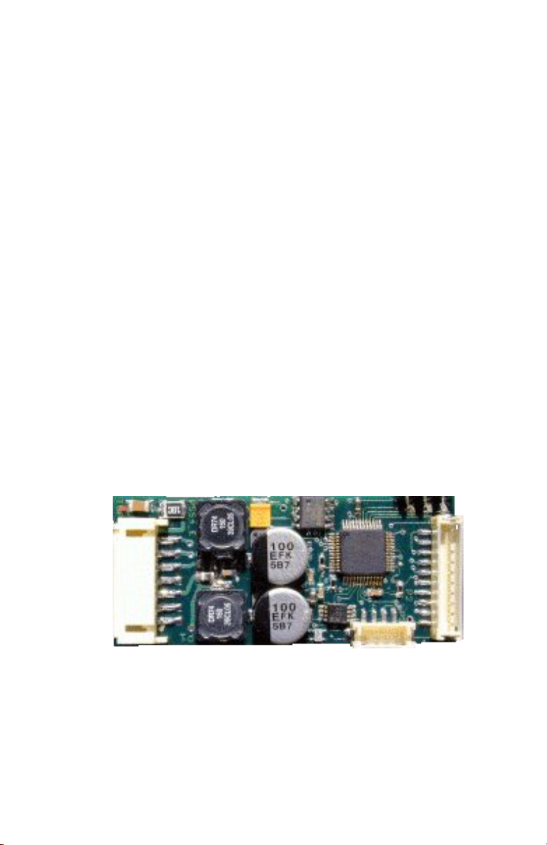
Getting Acquainted
One of the ideas behind the P5 system is to tailor the system to your
needs to avoid unnecessary expense. The P5 Basic (Board only) system
includes the sound board (pictured below), connectors C1 which
connects the speaker and power leads and C2 which is the computer
access jack. We also offer the P5 as a kit which includes the sound board
with a speaker and all connectors (C1, C2 and C3) appropriate to the
locomotive.
Additional components available include: volume switch
[6001-05], volume switch with reed switch[6020-05], volume switch
with reed switch and bare leads for Board Trigger 2, volume switch with
bare leads for Board Trigger 1, and volume switch with bare leads for
Board Triggers 1 & 2.
There are 3 connectors on the P5 board. The chart on the
following page shows the pin out for each. This chart also details the
length and coloring of the wire leads if you order the generic plugs.
The Sound Board & Connectors
C1
1
1
2
3
4
5
6
7
4 3 2 1
2
3
4
5
C2
6
7
8
9
10
C3
August 2008
- 4 -
Page 5

Connector Pin Out Chart
Connector: Pin Purpose Color Termination
C1:1 Power/DCC Green Bare
C1:2 Power/DCC Green Bare
C1:3 Speaker Brown SPOX-3
C1:4 Shield (unused) – –
C1:5 Speaker Brown SPOX-3
C1:6 Alternate Power + Violet Bare
C1:7 Alternate Power - Black Bare
C2:1 Trigger Ground Blue Bare*
C2:2 P5 Trigger 2 Orange Bare*
C2:3 Trigger Ground Blue Bare*
C2:4 P5 Trigger 1 Brown Bare*
C2:5 Ground Black JST ZHR-3
C2:6 Expansion Signal White JST ZHR-3
C2:7 +3V Expansion Red JST ZHR-3
C2:8 Ground Black Volume Switch
C2:9 Volume Level Yellow Volume Switch
C2:10 Volume +3V Red Volume Switch
C3:1 Ground Black Jack
C3:2 Hi Speed White –
C3:3 Computer Signal Yellow Jack
C3:4 +5V Red Jack
* THESE CONNECTIONS CAN TERMINATE IN EITHER NOTHING, BARE WIRE OR REED
SWITCHES, DEPENDING UPON THE TYPE OF ENGINE THE UNIT IS ORDERED FOR.
August 2008
- 5 -
Page 6
Initial Checkout
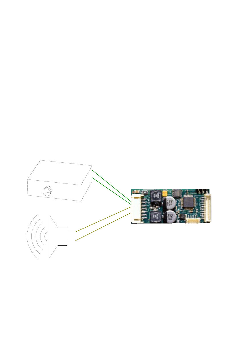
The Basic Bench Test
Each system is tested before shipping but we recommend that you
hook things up on your workbench, play with the system and get
comfortable with the components before installation.
The speaker and power supply connect to C1. The speaker connects
to the speaker jack (brown wires). Hook your bench power supply to the
green wires. A power source of any polarity is acceptable. The maximum
peak input voltage is 30 volts. If you are using a volume switch plug it
into C2. This connector can only be inserted in one direction, so if you
wired your own following the pin out chart on page 5 or are using one
we supplied, it should work correctly.
When the power rises above 9 volts you should hear sound. If you
are using our volume switch, raise and lower the volume. The system
will play the idle sounds.
August 2008
- 6 -
Page 7

Advanced Checkout
In order to play moving sounds you will need at least one of the
following:
1. A DCC power source connected to C1.
2. A switch (i.e. a reed switch) connected to C2:3,4.
3. The Auxiliary Input Board [P5T] to sense motor voltage.
SEE APPENDIX B FOR THE P5T CHECKOUT
DCC Checkout
The sound board default address is 3. Select 3 on your DCC
controller. Turn the speed up and down. Sounds should play in
coordination with the changing speed commands. Test the function
buttons. The default function button assignment chart can be found on
page 11.
Reed Switch Checkout
If you will be using a reed switch and magnets to sense speed, you
may wish to hook them up and experiment with the magnets to get an
idea of the sensitivity of the reed switches. This will help you decide how
to mount them in the locomotive or car. Whenever the trigger (C2:4) is
connected to the trigger ground (C2:3) the system sees motion. The first
closure should play the start toots and the starting bell.
August 2008
- 7 -
Page 8

Standard Sounds and Effects
Most sounds play automatically based on train speed. Many sounds
can also be set to play using designated trigger inputs. The following
section describes the standard sound system configuration.
All Systems
Whistle/Horn: Toots when starting (2 forward, 3 reverse) and stopping (one
toot). Crossing whistle sequence plays when you reach the Whistle/Horn
play speed. You must slow down to at least 75% of the play speed in
order to have it play again when you speed back up.
Bell: Plays when you first start moving and just before stopping. You must reach
twice the bell stopping speed in order to replay the bell when stopping.
The bell will not replay unless 35 seconds have elapsed since the last
time it played.
Coupler Clank: Plays when you come to a stop in reverse; will not replay until
you go forward and back up again.
Brake Screech: Plays just before stopping.
Diesel Systems
Air Pop: Plays periodically during idle.
Brake Release: Plays as the engine starts moving.
Steam Systems
Blow Down: A longer and more vigorous steam release that clears the flues.
Plays as you slow down.
Steam Release: Plays after you come to a stop.
Generator: Basically runs all the time but the engineer will shut it down if the
engine sits in idle for awhile. Comes back on when voltage approaches
the start voltage.
Air-Pump: Plays in idle to maintain air pressure.
Air-Pump 2: A sustained compressor run that restores air pressure after it’s been
depleted.
Rod clank: Plays at slow speed
Hiss: Plays at low speed, clears the cylinders of excess water.
Coal Shoveling: Plays periodically while engine sits at idle.
August 2008
- 8 -
Page 9

Triggered Sounds and Effects
The P5 board has two trigger inputs, normally assigned to speed. The
Auxiliary Input Board [P5T] allows you to trigger additional sounds
using reed switches or outputs from remote control receivers. The
following section describes sounds which may be assigned to triggers or
DCC functions. Of course, any sound can be assigned to a trigger. See
the tables on pages 12 and 22 for factory default trigger and DCC
Function assignments.
All Systems
Tunnel Fade: This trigger causes the volume to fade down to a lower
setting. When the input is triggered again, the volume will come
back to the prefade setting.
Doppler: In diesel, when you trigger this input, the next time the
crossing horn plays it will go thorough the pitch shift that you hear
as a train is speeding toward and then away from you. Doppler is
speed sensitive. In steam, triggering this effect will cause the pitch
of the chuff to shift as the engine approaches and a second
triggering will cause the pitch to shift back to normal.
Working/Drifting: An effect that makes the locomotive sound like it is
struggling with a heavy train or coasting into a station.
Diesel Only
Dynamic Brake: A triggered only sound. It is almost a tone which
results from using diesel drive motors as generators.
Rev Up/Down: Causes the prime mover sound to go to the next/previous
rev. The sound will return to the corresponding rev based upon
speed changes.
Steam Only
Water Fill: Plays 10 seconds after trigger unless set to manual.
Coal Loading: Plays 10 seconds after trigger unless set to manual.
Mallet Mode: Plays a second set of chuffs, moving in and out of phase
with the main chuff.
Second Chuff Trigger: Plays chuffs independently of the main chuff
trigger.
August 2008
- 9 -
Page 10

Control Variables (DCC CV)
Versions of the P5 firmware after 1.00 support the following Control
Variables. These can be programmed on the program track or using
service mode programming.
OPS MODE IS NOT CURRENTLY SUPPORTED.
CV Description Default Value
1 Short Address 3
17 Long Address 0
18 Long Address 3
49
0 = Speed from Triggers; ≠ 0, speed from
0
DCC
50 The DCC Value where motion starts. 2
51 The DCC Rate (Speed vs. Throttle) 100
52 Seconds to simulate DCC if DCC signal is lost.
0 = Forever
53 Seconds in idle before shutdown.
0 = Never shutdown
0
0
August 2008
- 10 -
Page 11

Computer Interface
The Computer Interface is an optional accessory that enables
complete customization of all sounds.
The Computer Interface consists of a CD and serial cable for use
with Windows 95, 98, 98SE, ME, 2000, XP and Vista. If your computer
does not have a serial port (many recent machines do not) you will need
a USB to serial adapter. The CD contains software to customize sounds
from the Phoenix Sound library. Connecting the serial cable to the board
through the access jack allows you to download sounds for different
engines and change the following:
● Individual sound volumes
● Manual vs. Programmed response for bells and whistles
(horns)
● Assign sounds to terminals and DCC functions
● Adjust how often a sound plays
● Change shutdown time
● Change and modify chuff rhythm, compression and tone
● Configure and fine tune for various control systems such
as: AC, DC, DCC, MTS, Locolinc®, Train Engineer, RCS,
Reeds and Air Wire 900
● plus many other features you will discover as you
familiarize yourself with the system
All adjustments, upgrades and sound loading can be made
through the Access Jack. You will not need to take the model apart after
installation is complete.
August 2008
- 11 -
Page 12

Initial Trigger and Function Assignments
Trigger Defaults
C2 Pin Diesel Steam
1 Trigger Ground Trigger Ground
2 Slave Mode Second Chuff
3 Trigger Ground Trigger Ground
4 Speed Main Chuff
DCC Function Defaults
Address: 3
Function Diesel Steam
F1 Bell Bell
F2 Manual Horn Manual Whistle
F3 Coupler Clank Coupler Clank
F4 Crossing Horn Crossing Whistle
F5 Working Coal Loading
F6 Dynamic Brake Water Fill
F7 Volume Up Volume Up
F8 Volume Down Volume Down
F9 Rev Up Blow Down
F10 Unassigned Unassigned
F11 Unassigned Unassigned
F12 Shutdown Shutdown
August 2008
- 12 -
Page 13

Installation Guidelines
Speaker – Use the largest speaker that can reasonably fit your available
space. For best acoustics the speaker should be sealed to the floor
so that sound going out the front of the speaker is isolated from the
back side.
Volume Switch and Access Jack – Unobtrusive but accessible.
Typically in the floor of tenders and boxcars and on the fuel tanks
of diesels. Many models have removable pieces, doors, etc. where
you can mount these. Volume switch: ¼” hole; Jack: 9/32” hole.
Mounting the Sound Board – Make sure that the sound board will not
touch anything metal. Use the foam tape provided; many modelers
prefer hook and loop tape.
Reed Switches – If you use track magnets and reed switches to trigger
sounds and effects, keep the reed
switches away from the speaker magnet
and strong motor magnets. Reed
switches should ride about ¼’’ above
rail head and be spaced ½’’ on either
side of center. However, it should be
noted that you need the Auxiliary Input
Board, P5T, to connect these reed
switches. Reed Switch: ¼” hole.
Speed Sensor – You may need to experiment to get reliable triggering
from a rotating axle with magnets on it. After mounting the
magnets on the axle, hold the reed switch in various positions and
hook something to the reed so you can
tell when the switch is closed. An ohm
meter with a beeper works great. You
can point the reed switch directly at
the axle/magnets but there will be less
motion tolerance. With the magnets
sweeping the side of the reed switch
(as shown) a clearance of about 3/16’’
is usually right. If you are too close
you may get extra closures—one as the
magnet approaches, and one as it
leaves.
August 2008
- 13 -
Page 14

Troubleshooting
Wrong directional toots – Swap wires between C3:1 and C3:2 on the
Auxiliary Input Board, P5T, or change the track polarity using the
Computer Interface.
No Sound – Start by rechecking the wiring to the speaker, volume
switch, and power connector. A connection may have been missed
or become loose. Measure the voltage applied to the power
connector when you think the board should be on. 7 volts is
needed for the board to make sound. It may be something as
simple as the volume being turned down, try raising the volume.
Also check the volume switch and its connectors to make sure
there is no damage, broken connections or that the switch
terminals are not touching anything metal.
Low Volume – If the volume is lower than your chosen setting the board
may not be receiving full power at connector C1.
Erratic Chuffing – The axle magnets may not be mounted
symmetrically. Also, if the reed switch is not mounted to the truck,
the distance to the magnet might change during curves. The wires
coming from the reed switch might be broken or loose. Engines
with built-in contacts (Bachmann Spectrum) may require cleaning
or oiling of the contacts. Contact Problems are the normal cause
for faster then normal chuffing.
Whistle too frequent – The whistle plays based upon the speed reaching
the whistle play speed threshold. If the train slows down in curves
or at grades this may cause additional whistle triggering. Running
at a slightly higher or slower speed may help. If a reed switch is
used to blow the whistle, triggering may occur due to unexpected
magnetic fields such as those generated by the speaker. Make sure
your reed switch is not mounted too close to your speaker.
August 2008
- 14 -
Page 15

Technical Specifications
Length – 2.00 in; 50.80 mm
Width – 0.875 in (7/8”); 22.225 mm
Height – 0.4375 in (7/16”); 11.1125 mm
Max Volts at Track – 30V.
Power Consumption – Varies with volume; can go as high as 1000mA if
at max volume; typical is less than 100mA - medium volume.
Amplifier – 6 Watts maximum.
Speaker Load – 4 Ohms or greater; two 8 Ohm speakers in parallel is
fine.
Access Jack Diagram
THE PLUG IS A STANDARD 2.5MM STEREO (TRS) PLUG. THE SUPPLIED JACK IS FULLY
INSULATED FROM THE MOUNTING HOLE. OTHER 2.5MM JACKS MAY BE SUBSTITUTED -
BUT MAKE SURE THAT THERE IS NO GROUND PATH BETWEEN THE COMMON TO ANY OF
THE POWER INPUTS (C1:1,2 OR 6).
August 2008
- 15 -
Page 16

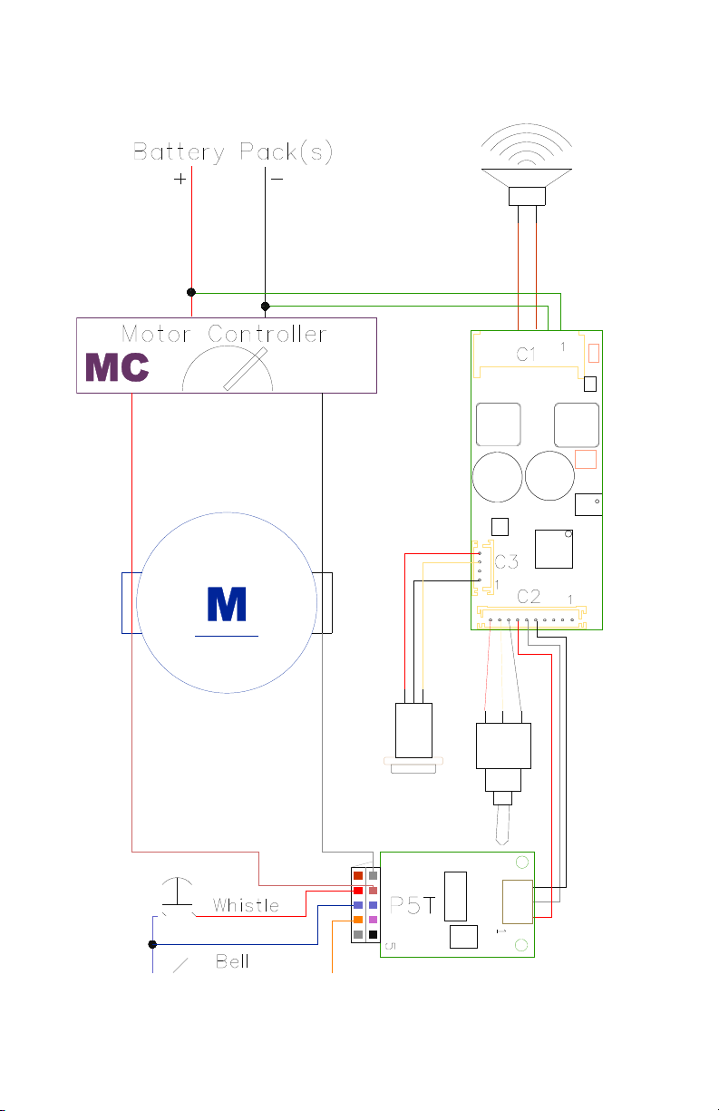
Appendix A: Wiring Diagrams
Basic DCC
August 2008
- 16 -
Page 17

Air Wire 900
August 2008
- 17 -
Page 18

Aristocraft/Crest Train Engineer
NOTE: P5T DOES NOT DRIVE THE MOTOR, RATHER IT READS THE MOTOR
VOLTAGE FROM THE 55490RF OUTPUT TO DETERMINE SPEED.
August 2008
- 18 -
Page 19

Locolinc®
August 2008
- 19 -
Page 20

RCS
RCS Basic Shown. Additional diagrams and options available from
RCS directly and from the RCS website: http://www.rcs-rc.com.
August 2008
- 20 -
Page 21
Basic Ride On
August 2008
- 21 -
Page 22

Appendix B: P5T Auxiliary Input Board
The P5 system is designed as a modular system, consisting of a base
board and expansion boards. This optional board adds 6 Trigger inputs
and a pair of motor voltage inputs to the P5 system. This is useful with
conventional remote control systems where train speed is determined by
reading motor voltage and where more than 2 trigger inputs are needed.
DCC SYSTEMS WOULD ALMOST NEVER NEED THE P5T.
Auxiliary Input Board (P5T) Checkout
If you are using the Auxiliary Input Board, you can hook a variable
voltage to Motor Inputs M1 & M2. Connecting the pins T1 through T6 to
ground (GND) will activate the associated sounds and effects.
Top Bottom
T2 T3
T1 T4
GND GND
M2 T5
M1 T6
M1 Indicator
Terminal Color Diesel Steam
Top Row
T2 Black Dynamic Brake Water Fill
T1 Violet Working Drifting
GND Blue Ground
M2 Orange Motor
M1 Gray Motor
Bottom Row
T3 White Rev Up Coal Load
T4 Yellow Bell
GND Blue Ground
T5 Red Crossing Horn/Whistle
T6 Brown Manual Horn/Whistle
August 2008
- 22 -
Page 23

Warranty
The BigSound™ electronic board is manufactured to the highest
standards using the latest assembly technology and quality,
conservatively rated parts. We are dedicated to producing the world’s
finest sound system for years of railroading enjoyment.
The materials and operation of the BigSound™ electronic board and
associated system kit components supplied by Phoenix are guaranteed to
perform correctly for one year when installed and operated according to
the instruction manual. In the unlikely event that your BigSound™
system fails, please call or e-mail us so that we may evaluate the
situation and save any unnecessary shipping. We prefer to prescreen
returns because frequently there is a simple explanation for any
perceived problem you may be experiencing. Repairs and or
replacements covered by this warranty are at no cost. However return
shipping may be charged, especially if you return your system in an
engine, tender, box car or the like. A service fee may be assessed if it is
determined that the failure was not due to any Phoenix supplied
components.
Phoenix Sound Systems, Inc. cannot be liable for damage to the
system during shipping to our facilities due to mishandling, inadequate
packaging or similar circumstances beyond our control. Please be sure to
package the BigSound™ in a secure, static safe manner.
Please read the handbook and any included installation notes prior to
installation and operation of your BigSound™ system. Contact us if you
have questions or are unsure about any aspect of installation or operation.
August 2008
- 23 -
 Loading...