


MC73110
Advanced 3-Phase Motor Control IC
Developer’s Kit Manual
Performance Motion Devices, Inc.
55 Old Bedford Road
Lincoln, MA 01773
Revision 1.1, October 2003

NOTICE
This document contains proprietary and confidential information of Performance Motion Devices,
Inc., and is protected by federal copyright law. The contents of this document may not be disclosed
to third parties, translated, copied, or duplicated in any form, in whole or in part, without the express
written permission of Performance Motion Devices, Inc.
The information contained in this document is subject to change without notice. No part of this
document may be reproduced or transmitted in any form, by any means, electronic or mechanical,
for any purpose, without the express written permission of Performance Motion Devices, Inc.
Copyright 1998, 1999, 2000, 2001, 2002, 2003 by Performance Motion Devices, Inc.
Navigator®, Pro-Motion® and C-Motion® are registered trademarks of Performance Motion Devices, Inc.
ii
MC73110 Developer’s Kit

Warranty
Performance Motion Devices, Inc. (PMD) warrants performance of its products to the specifications
applicable at the time of sale in accordance with Performance Motion Devices, Inc.’s standard warranty.
Testing and other quality control techniques are utilized to the extent Performance Motion Devices,
Inc. deems necessary to support this warranty. Specific testing of all parameters of each device is not
necessarily performed, except those mandated by government requirements. Performance Motion
Devices, Inc. reserves the right to make changes to its products or to discontinue any product or service
without notice, and advises customers to obtain the latest version of relevant information to verify,
before placing orders, that information being relied on is current and complete. All products are sold
subject to the terms and conditions of sale supplied at the time of order acknowledgement, including
those pertaining to warranty, patent infringement, and limitation of liability.
Safety Notice
Certain applications using semiconductor products may involve potential risks of death, personal
injury, or severe property or environmental damage. Products are not designed, authorized, or
warranted to be suitable for use in life support devices or systems or other critical applications.
Inclusion of Performance Motion Devices, Inc. products in such applications is understood to be fully at
the customer’s risk. In order to minimize risks associated with the customer’s applications, adequate
design and operating safeguards must be provided by the customer to minimize inherent procedural
hazards.
Disclaimer
Performance Motion Devices, Inc. assumes no liability for applications assistance or customer product
design. Performance Motion Devices, Inc. does not warrant or represent that any license, either express
or implied, is granted under any patent right, copyright, mask work right, or other intellectual property
right of Performance Motion Devices, Inc. covering or relating to any combination, machine, or process
in which such products or services might be or are used. Performance Motion Devices, Inc.’s publication of information regarding any third party’s products or services does not constitute Performance
Motion Devices, Inc.’s approval, warranty or endorsement thereof.
MC73110 Developer’s Kit
iii

Related Documents
MC73110 Advanced 3-Phase Motor Control IC Product Manual (MC73110PM)
Electrical Specifications, Theory of Operations, and Command Reference for MC73110 IC.
iv
MC73110 Developer’s Kit

Table of Contents
1.0 Product Overview .............................................................................. 7
2.0 Installation ......................................................................................... 9
2.1 Software ........................................................................................................................................................ 11
2.2 Documentation .......................................................................................................................................... 11
2.3 Connection Configurations ....................................................................................................................... 12
2.4 Installation Sequence .................................................................................................................................. 13
2.5 Required Hardware ..................................................................................................................................... 13
2.6 Preparing the Card for Installation............................................................................................................ 14
2.7 Connecting to the Card .............................................................................................................................. 15
2.7.1 Initial Setup .............................................................................................................................. 15
2.7.2 Power Connector (J1) .............................................................................................................. 16
2.7.3 Motor Feedback Connector (J2) ............................................................................................. 16
2.7.4 Motor Connector (J4) ............................................................................................................. 17
2.7.5 Host Connector (J6) ................................................................................................................ 17
2.7.6 Serial Port Connector (J7) ....................................................................................................... 18
2.8 Applying Power.......................................................................................................................................... 18
2.8.1 Card Reset ................................................................................................................................. 18
2.8.2 LED Status Indicators ............................................................................................................ 18
2.9 Software Installation ................................................................................................................................... 19
2.10 First Time System Verification................................................................................................................. 19
3.0 Using Pro-Motion ............................................................................ 21
3.1 Communication .......................................................................................................................................... 22
3.1.1 Axis Setup Wizard ................................................................................................................... 23
3.1.1 Step #1: Signal Output Settings ............................................................................................ 24
3.1.2 Step #2: Initialize Signal Sensing ........................................................................................... 24
3.1.3 Step #3: Safety Settings ........................................................................................................... 25
3.1.4 Step #4: Commutation .......................................................................................................... 25
3.1.4.1 Step #4a: Check Commutation .......................................................................................... 26
3.1.5 Step #5: Velocity Integrator Loop Parameters ..................................................................... 26
3.1.6 Step #6: Velocity Loop Parameters ........................................................................................ 26
3.2.6 Step #7: Current Loop Parameters ........................................................................................ 27
3.2.7 Step #8: Miscellaneous Settings ............................................................................................. 27
3.2 Main Window ............................................................................................................................................. 28
3.2.1 Project Window ....................................................................................................................... 28
3.2.2 Command Window ................................................................................................................ 29
4.0 Developing Your Own Applications with C-Motion ......................... 31
4.1 Theory of Use ............................................................................................................................................. 32
5.0 MC73110 Electrical Reference......................................................... 33
5.1 User-Settable Jumper Options .................................................................................................................. 33
5.2 Connecting to the Card .............................................................................................................................. 34
5.2.1 Power Connector (J1) .............................................................................................................. 35
5.2.2 Motor Feedback Connector (J2) ............................................................................................. 36
5.2.3 RS485 Connector (J3) .............................................................................................................. 37
5.2.4 Motor Connector (J4) ............................................................................................................. 37
5.2.5 Remote Switcher Connector (J5) ............................................................................................38
5.2.6 Host Connector (J6) ................................................................................................................ 39
5.2.7 Serial Port Connector (J7) ....................................................................................................... 39
MC73110 Developer’s Kit
v

vi
MC73110 Developer’s Kit

1.0 Product Overview
MC73110 Navigator/Pilot Magellan Motion Cards
Motor Control
IC
Number of axes 1 1, 2, 4 1, 2, 3, 4 1, 2, 3, 4
Package 64-pin TQFP 132-pin PQFP 144-pin TQFP PCI
100-pin PQFP 100-pin TQFP PC/104
Voltage 3.3 V 5 V 3.3 V 3 V
Function Velocity control Position control Position control Position control
Torque control Encoder input Encoder input Encoder input
Commutation Profile generation Profile generation Profile generation
Encoder input Commutation Commutation Commutation
Network Signal conditioning
communications Analog output
Multi-motor Trace buffer
Motor types Brushless DC DC servo DC servo DC servo
Brushless DC Brushless DC Brushless DC
Microstepping Microstepping Microstepping
Pulse & direction Pulse & direction Pulse & direction
Communication Standalone Parallel Parallel PCI, PC104
Serial Serial point-to-point Serial point-to-point
Serial multi-drop Serial multi-drop
CANbus
Loop rate 20 kHz 100 -150 Sec/axis 50 -75 Sec/axis 50 -75 Sec/axis
1
The MC73110 Motor Control IC is a single-chip, single-axis device ideal for use in intelligent 3-phase brushless
motor amplifiers. It provides sophisticated programmable digital current control with direct analog input of
feedback signals. It can be operated in voltage, torque, or velocity modes and supports standalone operation for
use with PMD’s motion processors, other off-the-shelf servo controllers, or via a serial port.
Navigator/Pilot-family Motion Processors provide programmable chip-based positioning control for brushed
servo, brushless servo, microstepping, and pulse and direction step motors. They are available in 1, 2 and 4-axis,
and in both single-chip and two-IC chipset configurations. These parts operate at 5V.
Magellan-family Motion Processors are state-of-the-art programmable chip-based positioning controllers for
brushed servo, brushless servo, microstepping, and pulse and direction step motors. They are similar to the
Navigator Motion Processors but provide increased capabilities including faster loop rate, CANBus communications, software-selectable motor type, and direct SPI bus output for serial DACs. They are available in 1, 2, 3, and
4-axis, and in both single-chip and two-IC chipset configurations. These parts operate at 3.3V.
PMD’s PCI and PC/104-bus motion cards are high performance general purpose motion cards for controlling
DC-brush, brushless DC, microstepping, and pulse & direction motors. Utilizing PMD’s Magellan Motion
Processors, these products are available in 1, 2, 3, and 4 axis configurations and have advanced features such as 16bit D/A analog output, and on-board high speed performance tracing.
MC73110 Developer’s Kit Manual
7

1
PMD Product Overview
8
MC73110 Developer’s Kit Manual
2.0 Installation
In This Section
Software
Documentation
Connection Configurations
Installation Sequence
Required Hardware
Preparing the Card for Installation
Connecting to the Card
Applying Power
Software Installation
First Time System Verification
The PMD MC73110 Developer’s Kit is an integrated board/software package that serves as an electrical and
software design tool for MC73110-based systems. The major components of the kit are:
Standalone MC73110-based card with 10 amp 3-phase brushless motor amplifier
Serial cable to communicate with PC
CD-ROM containing C-Motion and Pro-Motion software programs
MC73110 Product Manual
MC73110 Developer’s Kit Manual
2
The Developer’s Kit is a self-standing card supported by aluminum standoff 4.093" x 6.800" in size. The PCB
board is FR-4 four-layer with 2 oz. copper. The thickness is 62 mil. It accepts a single power connection of 18V to
48V, from which the card itself derives all other needed voltages using an on-board DC to DC converter device.
During initial setup and operation, a serial cable connects the card to a PC, which runs PMD’s Pro-Motion exerciser
program. The serial port can be operated in point-to-point mode, or multi-drop mode. The card can also be
operated standalone, without serial port connection. In this mode the card receives a command from an external
motion controller via analog or digital hardware signals. When operated in standalone mode, MC73110 parameters are loaded into the MC73110 at power up via an on-board serial EEPROM which is installed in an 8-pin DIP
socket located on the Developer’s Kit card.
The card drives a 3-phase brushless DC motor at up to 10 amps continuous current, 15 amps peak. A wide range
of motor inductances are supported. An on-card temperature sensor can be used to alert the user of an overtemperature condition on the amplifier.
MC73110 Developer’s Kit Manual
9

2
Installation
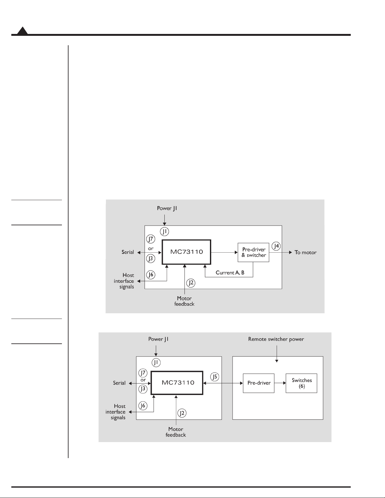
The following diagram provides a summary of the functions of the MC73110 Developer Kit card.
The Developer’s Kit can be used for a number of purposes. It is useful as a:
‘Ready to go’ system that exercises the MC73110
Reference design for an MC73110-based amplifier/drive
Pre-production system with which the user’s application can be developed,
and motors can be tested
Test system from which various switching power block sections can be tested
10
MC73110 Developer’s Kit Manual

2.1 Software
Two major software packages are provided with the MC73110 Developer's Kit cards: Pro-Motion, an interactive
Windows-based exerciser program and C-Motion, a C-language library which simplifies the development of
motion applications for MC73110 Developer's Kit cards.
Pro-Motion is a sophisticated, easy to use exerciser program that allows you to set and view all card parameters,
and exercise all card features. Pro-Motion features include:
Project window for accessing card parameters
Ability to save and load current settings
Motor-specific parameter setup
Command window for direct text command entry.
Communications monitor that echoes all commands sent by Pro-Motion to the card.
C-Motion provides a convenient set of callable routines that comprise all of the code required for controlling your
MC73110 Developer's Kit card. C-Motion includes the following features:
Axis virtualization
The ability to communicate to multiple MC73110 Developer’s Kit cards
Can be easily linked to any “C/C++” application
Installation
2
Pro-Motion is described in section 3, Using Pro-Motion, page 21, C-Motion is described in detail in section 4, Developing
Your Own Applications with C-Motion, page 31.
2.2 Documentation
There are two manuals specifically associated with the MC73110 card. A brief description of each is listed below.
Component Name Description
part number
MC73110PM MC73110 This is the complete description of the MC73110 IC.
Product Manual It includes electrical specifications, theory of operations,
DK73110M MC73110 This document guides you through installation and operation
Developer’s Kit Manual of the MC73110 Developer’s Kit. It describes the Developer’s
To download these documents, or request that they be sent to you, visit the PMD website at www.pmdcorp.com
or contact your PMD representative.
and a programmer’s command reference.
Kit card and software, and provides complete schematics
for the card.
MC73110 Developer’s Kit Manual
11
2
Internal
switcher
configuration
Installation
2.3 Connection Configurations
There are two major connection configurations of the MC73110 Developer’s Kit. The first is ‘internal switcher’,
and the second is ‘remote switcher’.
Internal switcher means that the Developer’s Kit uses its internal 10 Amp continuous (15 amp peak) on-board
MOSFET switchers and current sense circuitry to form a complete standalone intelligent amplifier card. This is the
normal operating state of the system, and the most convenient to use when initially working with the MC73110
Developer’s Kit.
Remote switcher means that an external switching triple half-bridge and associated current sense and conditioning
circuitry is installed. Section 5, Electrical Reference, page 33, provides complete details on the signals that are required
to connect to an external amplifier. This configuration is useful for prototyping with a custom-designed amplifier
for the purpose of verifying your own amplifier design, or driving motors with a larger current capacity than 10
Amps continuous.
The diagrams below illustrate these two configurations.
Remote
switcher
configuration
12
MC73110 Developer’s Kit Manual

2.4 Installation Sequence
For a normal installation of a MC73110 Developer’s Kit card, you will need to configure your card for the
connection configuration you will be using (internal or remote). Configuration of the MC73110 Developer’s Kit
card is described in detail in section 2.6, Preparing the Card for Installation, see page 14.
Next you will need to connect your system’s motors, encoders, amplifiers, and sensors as desired to operate your
motion hardware. A description of the connections that are made for the MC73110 Developer’s Kit card is found
in section 2.7, Connecting to the Card, see page 15.
Once this hardware configuration is complete, you should then install the software. Installation of the software is
described in section 2.9, Software Installation, see page 19.
The final step to finish the installation is to perform a functional test of the finished system. This is described in
section 2.10, First Time System Verification, see page 19.
Once all of the above has been accomplished installation is complete, and you are ready to operate the card.
2.5 Required Hardware
To operate the MC73110 Developer’s Kit card with Pro-Motion, the Windows-based exerciser program, you will
need the following hardware:
Installation
2
The recommended platform is an Intel (or compatible) processor, Pentium or better, 5 MB of
1
available disk space, 32MB of available RAM, and a CDROM drive. The PC operating system
required is Windows 9X/ME/NT/2000/XP.
A 3-phase Brushless DC Motor with Hall sensors and optional quadrature encoder feedback
2
with index.
Cables as required to connect to the MC73110 Developer’s Kit card to your motor, to your
3
encoder, to the card power input, to the analog or digital command signals. In addition you
will connect the PC to the card via an included DB-9 cable. For complete descriptions of these
connections see section 2.7, Connecting to the Card, page 15.
MC73110 Developer’s Kit Manual
13
2
Installation
2.6 Preparing the Card for Installation
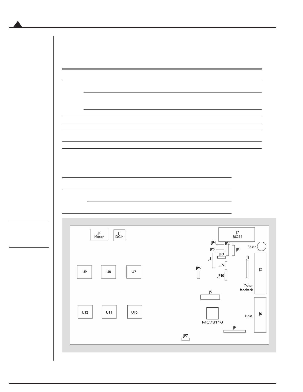
The following table shows the user-settable jumper options for the MC73110 Developer’s Kit card. For jumper
locations see the diagram on the bottom of the page.
Jumper Jumper Description
JP1, JP2 1-2 Selects RS-232 communication using on-board transceiver.
JP3-JP5 1-2 Reserved, must be set to 1-2
JP6, JP7 1-2 Selects use of on board amplifier/switcher. This is the default setting.
JP9, JP10 1-2 Reserved, must be set to 1-2.
setting
This is the default position of this jumper.
2-3 Selects RS-485 communication using user-provided daughtercard. For a
complete description of the electrical requirements of this daughtercard,
see section 5.2.3, RS-485 Connector, page 39.
3-4 Reserved
2-3 Selects use of remote amplifier/switcher. This setting is useful to
verify custom amplifier design or to connect to more powerful switching blocks.
In addition, the following resistor packs should be installed depending on whether single or differential quadrature encoders are used.
Resistor How to set Description
pack
J8 Installed If you are using differential connections
this is the default setting leave the resistor pack installed.
Removed If you are using single-ended encoder connections,
remove the resistor pack.
Figure 1-1.
Location of
various board
elements
14
MC73110 Developer’s Kit Manual

2.7 Connecting to the Card
There are a total of seven connectors that can be used with the MC73110 Developer’s Kit card as follows:
Connector Name Function
J1 Power Provides operating power to the Developer’s Kit card.
J2 Motor feedback Inputs various motor-related signals.
J3 RS-485 Provides communication to/from the card when a
multi-drop RS485 is used.
J4 Motor Provides high voltage, high current connections to the
motor from the amplifier output.
J5 Remote switcher Inputs and outputs various signals for use with a
remote switching block.
J6 Host Inputs and outputs various non-motor command and
feedback signals to/from the Developer’s Kit card.
J7 Serial port Provides RS-232 communication to/from the card using
an on-card transceiver driver chip. This connector is
designed to interface without null-modem or other
changes to a DB-9 PC serial port.
Here is a summary of the connector types expected for these 7 connectors:
Installation
2
Connector Signal type # pins Type
J1 High power 2 Through-hole terminal block (screw connection)
J2 Low power 14 Side-facing single row shrouded header
J3 Low power digital 5 1-in-line 0.100” pitch header
J4 High power 3 Through-hole terminal block (screw connection)
J5 Low power 16 8 x 2 vertical header (2mm pitch)
J6 Low power 12 Side-facing single row shrouded header
J7 Low power digital 9 Side-facing D-sub 9 (Female)
digital & analog (1-in-line 0.100” pitch friction lock header)
digital & analog
digital & analog (1-in-line 0.100” pitch friction lock header)
2.7.1 Initial Setup
To initially set up the Developer’s Kit card for checkout and verification, four connectors must be used - J1
(Power), J2 (motor feedback), J4 (motor), and J7 (serial port). In addition, the host connector (J6) is frequently
used during testing after initial setup, in which case the serial port becomes optional. The signal connections for
these connectors are indicated in the following sections. For a complete description of all connectors see section 5,
Electrical Reference, page 33.
MC73110 Developer’s Kit Manual
15

2
Installation
2.7.2 Power Connector (J1)
The power connector provides power to the card. All other voltages used by the card are derived from this central
supply using an on-card DC-DC converter. The voltage provided at these connections matches the voltage at
which the motor will be driven.
Pin # Signal Description
1 V+ 18 - 48V. Current capacity specification should be
2 PowerGnd Ground return for V+
name
maximum motor drive + 1amp (to power the card)
2.7.3 Motor Feedback Connector (J2)
The motor feedback connector inputs various motor-related signals to the Developer’s Kit card. All these signals
are low power, low voltage digital or analog signals.
Pin # Signal Description
1 +5V This signal provides 5V.
2 GND This signal provides the digital return.
3 QuadA+ This input signal provides the high side of the differential quadrature input for encoder
4 QuadA- This input signal provides the low side of the differential quadrature input for encoder
5 QuadB+ This input signal provides the high side of the differential quadrature input for encoder
6 QuadB- This input signal provides the low side of the differential quadrature input for encoder
7 Index+ This input signal provides the high side of the differential quadrature input for the
8 Index- This input signal provides the low side of the differential quadrature input for the Index
9 GND This signal provides the digital return.
10 HallA These signals are the Hall sensor inputs. For logic “0”, the signal should be lower than
11 HallB 0.5V; for logic “1”, the signal should be greater than 1.5V.
12 HallC
13 TachIn+ This is the positive input signal for the analog tachometer signal. This signal represents
14 TachIn- (GND) This is the negative input for the analog tachometer signal. The input range is +/- 60V.
This is often useful to power the encoder circuitry.
phase A. For more information on connecting encoders see section 2.6, Preparing the
Card for Installation, page 14. If unused this signal may be left unconnected.
phase A. When using a single-ended encoder, this pin should be left unconnected. For
more information on connecting encoders see section 2.6, Preparing the Card for
Installation, page 14. If unused this signal may be left unconnected.
phase B. For more information on connecting encoders see section 2.6, Preparing the
Card for Installation, page 14. If unused this signal may be left unconnected.
phase B. When using a single-ended encoder, this pin should be left unconnected. For
more information on connecting encoders see section 2.6, Preparing theCard for
Installation, page 14. If unused this signal may be left unconnected.
Index signal. For more information on connecting encoders see section 2.6, Preparing
the Card for Installation, page 14. If unused this signal may be left unconnected.
signal. When using a single-ended encoder, this pin should be left unconnected. For
more information on connecting encoders see section 2.6, Preparing theCard for
Installation, page 14. If unused this signal may be left unconnected.
the instantaneous speed of the motor. The input range is +/- 60V. If unused this signal
may be left unconnected.
If unused this signal may be left unconnected.
16
MC73110 Developer’s Kit Manual

2.7.4 Motor Connector (J4)
The motor connector provides the high voltage 3-phase outputs from the amplifier/switcher to the motor.
Pin # Signal Description
1 MotorC Leg 3 of 3 motor coil connections
2 MotorB Leg 2 of 3 motor coil connections
3 MotorA Leg 1 of 3 motor coil connections
2.7.5 Host Connector (J6)
The Host connector inputs and outputs various non-motor related signals to/from the Developer’s Kit card
Pin # Signal Description
1 Estop This digital input provides an emergency stop signal to the Developer’s Kit card.
Although its function and interpretation are programmable, normally a high signal
(greater than 1.5V) indicates an emergency stop is not active; and a low signal (less than
.5V) indicates that it is active. If unused this signal may be left unconnected.
2 AmplifierDisable This digital output signal provides a programmable output signal indicating the internal
state of the MC73110. Normally, a low output indicates an error, while a high signal
indicates no error. In addition to being an output at this connector, this signal is also used
internally by the MC73110 Developer’s Kit card to shut down the amplifier’s switchers
when the amplifier operates in ‘internal switcher’ mode.
3 GND This signal provides a digital ground return.
4 DigitalCmdClk This digital input signal provides the SPI datastream ‘clock’ signal.
5 DigitalCmdData This digital input signal provides the SPI datastream ‘data’ signal
6 GND This signal provides a digital ground return.
7 +5V This signal outputs provides 5V to external circuitry.
8 n.c. —
9
10 AnalogCmd+ This analog input signal provides the positive input of the analog command. Depending on
how the MC73110’s control loop has been programmed, this signal represents the
desired voltage, torque or velocity. The input range is +/-10V. The reference input can be
differential or single-ended.
11 AnalogCmd- This analog input signal provides the negative input of the analog command. Depending
on how the MC73110’s control loop has been programmed, this signal represents the
desired voltage, torque or velocity. The input range is +/-10V. The reference input can be
differential or single-ended. When it is single-ended, AnalogCmd- must be connected to
AGND, pin 12.
12 AGND This signal provides an analog ground return
Installation
2
MC73110 Developer’s Kit Manual
17

2
Installation
2.7.6 Serial Port Connector (J7)
The RS-232 serial connector provides communication to/from the card using an on-card transceiver driver chip.
This connector is designed to interface without null-modem or other changes to the DB-9 PC serial port. These
signals are low power, low voltage digital or analog signals.
Pin # Signal Description
2 SrlXmt Serial transmit signal from the MC73110 Developer’s Kit transceiver chip.
3 SrlRcv Serial receive signal to the MC73110 Developer’s Kit card.
5 GND Ground
2.8 Applying Power
Once you have installed or removed the correct jumpers and resistor packs, and once you have made the correct
connections to your hardware, installation is complete and the Developer’s Kit is ready for operation.
Upon application of power through connector J1, the card will be in a reset condition. Assuming that the flash
hasn’t been programmed or that a serial EEPROM hasn’t been installed, the MC73110 will utilize its default
values, and therefore, the motor should remain stationary. If the motors do move or jump, power down the card
and check the amplifier and encoder connections. If anomalous behavior is still observed, call PMD or your
distributor for application assistance.
2.8.1 Card Reset
During card operations, if at any time you wish to reset the MC73110, you can use the reset button indicated in
diagram 2.1 on page 14. Pushing the button will reset the controller.
2.8.2 LED Status Indicators
The MC73110 Developer’s Kit card has two LEDs to indicate the status of the board. Once the card has been
powered up the green power status LED should light. After the AmplifierDisable output pin is driven to an
Amplifier enabled condition, the red LED should light as well. The table below summarizes this:
LED Name Function
color
Green Power Status The green LED is on when the board is powered up and the 3.3V is available.
Red Amplifier Status The red LED is on when the amplifier is ready. It is controlled by the AmplifierDisable
pin (pin 23) of the MC73110. Normally the red LED will be off after power up. See section
2.10, First Time System Verification, page 19, for more information.
18
MC73110 Developer’s Kit Manual

2.9 Software Installation
Locate the CD included in the Developer’s Kit. This CD contains software to exercise your board and source code
that will enable you to develop your own motion applications. The exercise software is designed to work with
Windows 95/98/ME or Windows NT/2000.
If you have autorun enabled, the installation process will start when you insert the CD. The installation program
will guide you through installing the software. Upon completion of the installation process, the following
components will be installed:
Pro-Motion - an application for communicating to and exercising the installed Developer’s Kit.
Refer to section 3, page 21, for operating instructions.
C-Motion - source code that can be used for developing your own motion applications based
on the MC73110. Refer to section 4, page 31, for further information. These files are installed in
the “C-Motion” folder, a sub-folder of the installation folder.
PDF versions of the Developer’s Kit manual, programmer’s reference and user’s guide. The
Adobe Acrobat Viewer is required for viewing these files. If the Adobe Acrobat Viewer is not
installed on your computer, you can download it from <http://www.adobe.com>.
Installation
2
2.10 First Time System Verification
After you have installed the card hardware, made the appropriate connections to your motor, and installed your
software, you are ready to perform a simple test that will determine whether your motor is connected correctly. The
following producedure should work for the majority of brushless motors, even if the gain parameters may not be
optimized for your particular motor. Note that at any time the Pause/Break key can be pressed to disable the
servo loops and motor output should the motor start to move erratically or uncontrollably.
Run Pro-Motion by double clicking the Pro-Motion icon on the desktop.
1
If Pro-Motion cannot find the DK Board verify the serial port connections and select the
2
appropriate COM port in the Interface dialog and click OK. Accept the default serial port
settings by clicking OK. Refer to section 3.1 Communication for more information.
If the Axis Wizard pops up click Cancel.
3
Select File/Open from the menu and open the StartupTest.pmd file. The parameters will be
4
uploaded to the DK Board and the amplifier will be enabled. Be prepared to hit the Pause/
Break key to disable the motor if improper motion is observed.
The motor should now rotate slowly in either the clockwise or counterclockwise direction. If
5
this occurs, the first time system verification has been completed succesfully. If not, recheck the
motor connections. If the trouble persists contact PMD or a PMD representative for assistance.
MC73110 Developer’s Kit Manual
19

2
Installation
20
MC73110 Developer’s Kit Manual

3.0 Using Pro-Motion
In This Section
Communication
Axis Wizard
Main Window
The Pro-Motion program facilitates the exercising of the MC73110. All chip parameters can be viewed and
modified via standard Windows controls.
Pro-Motion features:
Project window for accessing chip parameters via properties dialog boxes.
Command window for direct text command entry.
Communications monitor that echoes all commands sent by Pro-Motion to the MC73110.
3
MC73110 Product Manual
21

3
Using Pro-Motion
3.1 Communication
When Pro-Motion is started it will attempt to connect to the DK Board via the the serial port using the default
serial port settings. If it cannot communicate to the DK Board (or File/New is selected) the Interface selection
dialog is displayed. Make sure the interface setting is set to COM port and the selected port is the one the DK
Board is attached to.
If the serial interface (COM port) is selected in the Interface selection dialog, the serial communication configuration screen is displayed.
Make sure the serial cable is connected from the host computer’s COM port to the DK Board. Set the serial
interface parameters according to the default settings of 57600, None, 2, Point to point, 0. Click OK to attempt a
connection and proceed to the Axis Setup Wizard. If no connection is made the Interface selection dialog will be
displayed again allowing you to modify the interface parameters or run in demo mode.
22
MC73110 Developer’s Kit Manual

Using Pro-Motion
3.1.1 Axis Setup Wizard
Once communication has been established with the DK Board, the connected motors may be put in motion by
setting the appropriate Axis parameters.
When Pro-Motion is run for the first time the Axis Setup Wizard will start automatically to configure the axis. To
continue through the configuration process for all of the axis’ parameters, click ‘Next’ . To accept the default
values, click ‘Cancel’.
Individual Axis settings may be modified later via Pro-Motion’s Axis Properties dialog which is accessed by
right-clicking an Axis icon
in the Project window and selecting ‘Properties’.
3
The Axis Setup Wizard may be re-run at any time by selecting ‘Axis Wizard’ from Pro-Motion’s View menu.
MC73110 Developer’s Kit Manual
23

3
Using Pro-Motion
3.1.1 Step #1: Signal Output Settings
On the Signal Output Settings page of the wizard, select the appropriate PWM output mode, PWM limit,
PWM dead time and PWM output logic for the amplifier that is connected to the MC73110. The power on
default settings are shown below. If you are using the DK Board the PWM dead time should be be reduced to a
value of 32 which translates to 1.6 s.
3.1.2 Step #2: Initialize Signal Sensing
This step of the Axis Setup Wizard is used to select the Signal Sense parameters. The default signal sense is active
low. Users should check the Invert sense checkbox in the first column for any input signals which are active high.
The Event status column displays and resets the event status bits. The Activity status column displays the
activity status bits. The controls in this dialog are continually updated.
24
MC73110 Developer’s Kit Manual

Using Pro-Motion
3.1.3 Step #3: Safety Settings
This step of the Axis Setup Wizard is used to set the Safety parameters. The settings as shown in the following
figure will:
1. Disable the amplifier if the temperature exceeds 60 °C or the Emergency stop signal is set.
This particular configuration will latch the amplifer as disabled because the Amplifer Disable
Source is set to Amplifer error which is latched in the Event status register. (see Initialize
Signal Sensing)
2. Disable the servo loop if the Motion error exceeds 100000.
3
Refer to the MC73110 Product Manual for further information on these settings.
3.1.4 Step #4: Commutation
This step of the Axis Setup Wizard is used to set the Commutation parameters. If the Commutation mode is
set to Sinusoidal, the motor will commutate in hall-based mode until a hall signal transition occurs. The phase
angle parameter is read-only and cannot be set in the dialog. However, it can be set in the command window
using the SetPhaseAngle command. Please see the MC73110 Product Manual for further information on phase
initialization.
MC73110 Developer’s Kit Manual
25
3
Using Pro-Motion
3.1.4.1 Step #4a: Check Commutation
The commutation may be verified by running the motor in open loop mode. Set the motor command parameter
to a low value between 1% and 15%, keeping in mind that the motor may start to move at a rate proportional to
the motor command setting. Click the Open loop start button. If the motor is commutating properly, smooth,
continuous motion should occur in a single direction. Click the Stop button to stop motion. If the motor does
not move or motion is erratic verify that Phase counts and signal sense is set correctly. The signal sense can be
accessed by going back to the Signals page.
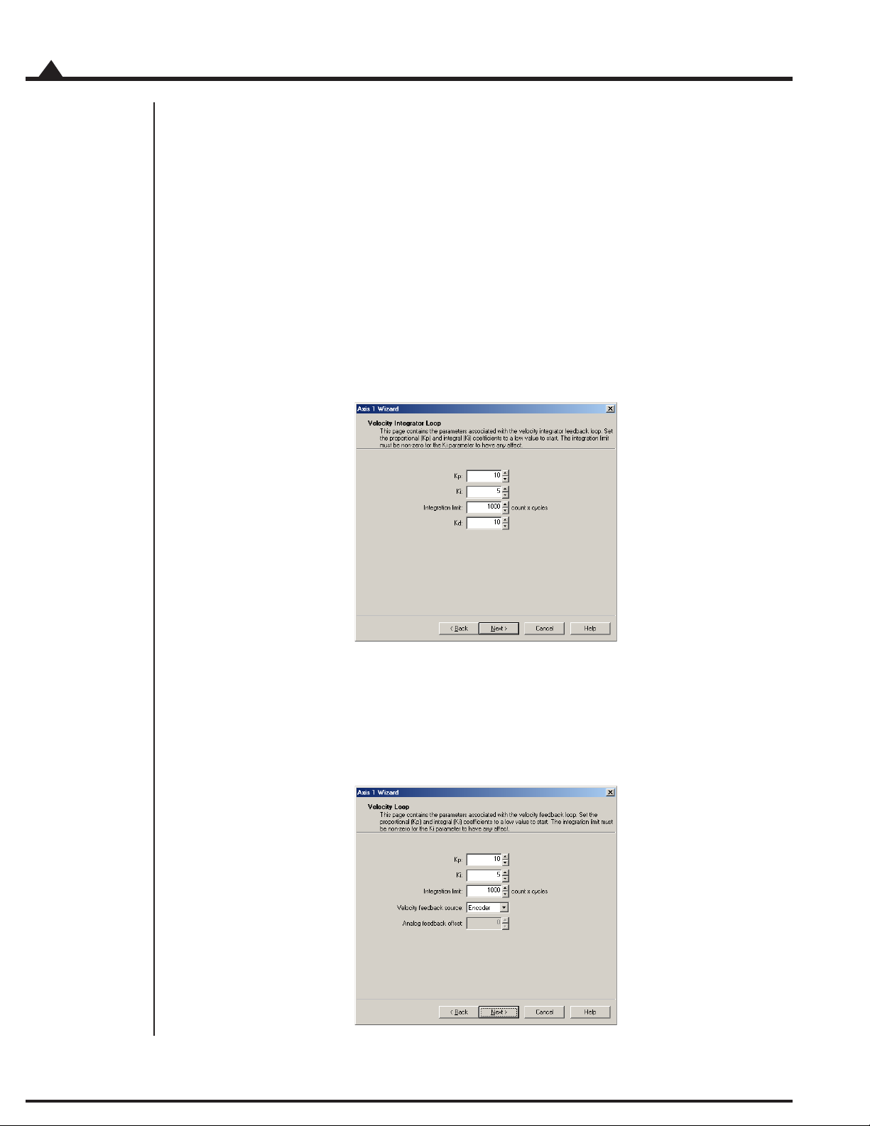
3.1.5 Step #5: Velocity Integrator Loop Parameters
This step of the Axis Setup Wizard is used to select the Velocity Integrator Loop parameters.
26
3.1.6 Step #6: Velocity Loop Parameters
This step of the Axis Setup Wizard is used to select the Velocity Loop parameters.
MC73110 Developer’s Kit Manual

3.2.6 Step #7: Current Loop Parameters
This step of the Axis Setup Wizard is used to select the Current Loop parameters.
Using Pro-Motion
3
3.2.7 Step #8: Miscellaneous Settings
The Miscellaneous Settings page contains the parameters for controlling the servo loops and motor dynamics.
The power-on default settings are shown in the following figure. When Motor Mode is off all the loops are
disabled (open loop mode) and Motor command controls the motor speed. The dynamics settings have no
effect in this mode.
When the command source is set to Analog the command for the velocity or current loops originates from the
analog input signal. When set to SPI the command for the velocity or current loops is a 16-bit value read from
the incoming SPI data stream. When set to Profile Generator the command is generated internally based on the
Velocity and Acceleration parameters.
Click the Finish button to update the motion processor parameters.
MC73110 Developer’s Kit Manual
27

3
Using Pro-Motion
3.2 Main Window
The main window is comprised of 3 subwindows, the project window, the command window and the output
window. The workspace and output windows are control bars which can be docked and resized at any location in
the main window or undocked and moved anywhere on the desktop. They can be removed by clicking on the X.
To re-display them, select the appropriate View menu item.
The are a couple of keyboard shortcuts that can be used at any time:
the Pause/Break key will disable the servo loops and motor output by setting MotorMode to
0 and MotorCommand to 0.
the Scroll Lock key will start and stop the output window from displaying communication
activity.
3.2.1 Project Window
The Project window displays the available DK Board’s and axes in a tree format. Double-clicking on a board or
axis will display the properties dialog for that item.
28
MC73110 Developer’s Kit Manual

Using Pro-Motion
3.2.2 Command Window
The Command window in Pro-Motion allows you to issue commands directly to the MC73110. The window has
a command line style interface that accepts all of the MC73110 commands. The MC73110 Programmer’s Reference
contains a full list of commands, along with their required parameters. The command window presents you with
the command prompt ‘>’. The following sequence shows a typical command session:
> Reset
Processor reset
> SetSignalSense 0x380
> SetPWMDeadTime 36
> SetPhaseCounts 2000
> SetLoopGain 0x0 50
> SetLoopGain 0x10 300
> SetLoopGain 0x20 30000
> SetVelocityScalar 2000
3
The Command window is not case-sensitive, so commands can be entered in any combination of upper and
lower case characters. As shown above, commands are entered as a sequence of command name followed by up
to 2 numeric parameters. Parameters can represent a single 16-bit word of data or a 32-bit double word of data,
depending on what is required by the particular command.
> SetLoopGain 1 300
In this example, the first parameter represents a 16-bit word that contains the selected loop gain, and the second
parameter represents a 32-bit word that contains the loop gain value.
All of the “Get” commands display the value returned by the chipset.
> GetEventStatus
0x0309
Some commands require a parameter for selecting the desired value.
> GetLoopGain 16
3000
In this example, 16 selects the loop gain number for which the value is retrieved. The Command window accepts
numeric parameters in either decimal or hexadecimal format. Pre-fixing a numeric parameter with “0x” enters that
number using hexadecimal format.
MC73110 Developer’s Kit Manual
29

3
Using Pro-Motion
> GetLoopGain 0x10
3000
Pressing the Tab key at any time will display a list of available commands depending what is already typed in the
command window. If nothing is typed in the command window then all of the available commands are
displayed. If, for example, “geta” is typed in the command window then the list will contain all the commands
starting with “geta”.
30
MC73110 Developer’s Kit Manual

4.0 Developing Your Own Applications with C-Motion
In This Section
Theory of Use
C-Motion is a “C” source code library that contains all the code required for communicating to the Motor Control
processor using the serial interface.
C-Motion includes the following features:-
Axis virtualization
The ability to communicate to multiple PMD motion processors
Can be easily linked to any “C/C++” application
Supports serial communication
4
The following files make up the C-Motion distribution:
C-Motion.h/C-Motion.c Definition/declaration of the processor command set
PMDw32ser.h/PMDw32ser.c Windows serial communication interface functions
PMDutil.h/PMDutil.c General utility functions
PMDtrans.h/PMDtrans.c Generic transport (interface) functions
PMDecode.h Defines the processor and C-Motion error codes
PMDocode.h Defines the control codes for processor commands
PMDtypes.h Defines the basic types required by C-Motion
C-Motion can be linked to your application code by including the above “C” source files in your application.
Then, for any application source file that requires access to the motion processor #include “C-Motion.h”.
MC73110 Developer’s Kit Manual
31

4
Developing Your Own Applications with C-Motion
4.1 Theory of Use
C-Motion is a set of functions that encapsulate the motion processor command set. Every command has as its
first parameter an “axis handle”. The axis handle is a structure containing information about the interface to the
motion processor and the axis number that the handle represents. Before communicating to the motion
processor, the axis handle must be initialized using the following sequence of commands:
// the axis handle
PMDAxisHandle handle;
// open serial interface to PMD processor and initialize handle to axis one
PMDSetupAxisInterface_Serial( &handle, PMDAxis1, 1 ); // COM1
Once the axis handle has been initialized, any of the motion processor commands can be executed. C-Motion.h
includes the prototypes for all motion processor commands as implemented in C-Motion. Refer to this file for
the required parameters for each command. The MC73110 Product Manual is the primary source for information
about the operation and purpose of each command.
Every C-Motion processor command returns a status code of type PMDresult. The return code for every
command executed should be checked before attempting to execute more commands.
PMDresult result,status;
result = PMDSetVelocity(&handle, 100000);
if (result != PMD_ERR_OK)
{
printf(“Error: %s\n”, PMDGetErrorMessage(result));
return;
}
Many commands require additional parameters. Some standard values are defined by C-Motion and can be used
with the appropriate commands. Refer to PMDtypes.h for a complete list of defined types. An example of
calling one of the C-Motion functions with the pre-defined types is shown below.
PMDSetConditionMask(&handle, PMDConditionMaskAmpDisable, PMDConditionOverTemp);
In addition to the processor commands, C-Motion provides several support functions. A subset of these are:
void PMDCloseAxisInterface(PMDAxisHandle* axis_handle);
should be called to terminate an interface connection.
32
char *PMDGetErrorMessage(PMDresult errorCode);
returns a character string representation of the corresponding PMD chip or C-Motion error code.
void GetCMotionVersion(PMDuint8* MajorVersion, PMDuint8* MinorVersion);
returns the major and minor version number of C-Motion.
MC73110 Developer’s Kit Manual

5.0 MC73110 Electrical Reference
In This Section
User-Settable Jumper Options
Connecting to the Card
5.1 User-Settable Jumper Options
The following table shows the user-settable jumper options for the MC73110 Developer’s Kit card. For jumper
locations see the diagram on the following page.
5
Jumper Jumper Description
JP1, JP2 1-2 Selects RS-232 communication using on-board transceiver.
JP3-JP5 1-2 Reserved, must be set to 1-2
JP6, JP7 1-2 Selects use of on board amplifier/switcher. This is the default setting.
JP9, JP10 1-2 Reserved, must be set to 1-2
In addition, the following resistor pack should be installed depending on whether single or
differential quadrature encoders are used.
Resistor How to set Description
pack
J8 Installed If you are using differential connections
setting
This is the default position of this jumper.
2-3 Selects RS-485 communiction using user-provided daughtercard. For a complete
description of the electrical requirements of this daughtercard,
see section 5.2.3, RS-485 Communications, page 39.
3-4 Reserved
2-3 Selects use of remote amplifier/switcher. This setting is useful to
verify custom amplifier design or to connect to more powerful switching blocks .
this is the default setting leave the resistor pack installed.
Removed If you are using single-ended encoder connections,
remove the resistor pack.
MC73110 Developer’s Kit Manual
33

5
Figure 5-1.
Location of
various board
elements
73110 Electrical Reference
5.2 Connecting to the Card
There are a total of seven connectors that can be used with the MC73110 Developer’s Kit card as follows:
Connector Name Function
J1 Power Provides operating power to the developer’s kit card.
J2 Motor feedback Inputs various motor-related signals.
J3 RS-485 Provides communication to/from the card when a
J4 Motor Provides high voltage, high current connections to the
J5 Remote switcher Inputs and outputs various signals for use with a
J6 Host Inputs and outputs various non-motor command and
J7 Serial port Provides RS-232 communication to/from the card using
multi-drop RS485 is used.
motor from the amplifier output.
remote switching block.
feedback signals to/from the developer’s kit card.
an on-card transceiver driver chip. This connector is
designed to interface without null-modem or other
changes to a DB-9 PC serial port.
34
MC73110 Developer’s Kit Manual

MC73110 Electrical Reference
Here is a summary of the connector types expected for these 7 connectors:
Connector Signal type # pins Type
J1 High power 2 Through-hole terminal block (screw connection)
J2 Low power 14 Side-facing single row shrouded header
digital & analog (1-in-line 0.100” pitch friction lock header)
J3 Low power digital 5 1-in-line 0.100” pitch header
J4 High power 3 Through-hole terminal block (screw connection)
J5 Low power 16 8 x 2 vertical header (2mm pitich)
digital & analog
J6 Low power 12 Side-facing single row shrouded header
digital & analog (1-in-line 0.100” pitch friction lock header)
J7 Low power digital 9 Side-facing D-sub 9 (female)
5.2.1 Power Connector (J1)
The power connector provides power to the card. All other voltages used by the card are derived from this central
supply using an on-card DC-DC converter. The voltage provided at these connections matches the voltage at
which the motor will be driven.
5
Pin # Signal Description
name
1 V+ 18 - 48V. Current capacity specification should be
maximum motor drive + 1amp (to power the card)
2 PowerGnd Ground return for V+
MC73110 Developer’s Kit Manual
35

5
73110 Electrical Reference
5.2.2 Motor Feedback Connector (J2)
The motor feedback connector inputs various motor-related signals to the developer’s kit card. All these signals are
low power, low voltage digital or analog signals.
Pin # Signal Description
1 +5V This signal provides 5V.
2 GND This signal provides the digital return.
3 QuadA+ This input signal provides the high side of the differential quadrature input for encoder
4 QuadA- This input signal provides the low side of the differential quadrature input for encoder
5 QuadB+ This input signal provides the high side of the differential quadrature input for encoder
6 QuadB- This input signal provides the low side of the differential quadrature input for encoder
7 Index+ This input signal provides the high side of the differential quadrature input for the
8 Index- This input signal provides the low side of the differential quadrature input for the Index
9 GND This signal provides the digital return.
10 HallA These signals are the Hall sensor inputs. For logic “0”, the signal should be lower than
11 HallB 0.5V; for logic “1”, the signal should be greater than 1.5V.
12 HallC
13 TachIn+ This is the positive input signal for the analog tachometer signal. This signal represents
14 TachIn- (GND) This is the negative input for the analog tachometer signal. The input range is +/- 60V.
This is often useful to power the encoder circuitry.
phase A. For more information on connecting encoders see section 2.6, Preparing the
Card for Installation, page 14. If unused this signal may be left unconnected.
phase A. When using a single-ended encoder, this pin should be left unconnected. For
more information on connecting encoders see section 2.6, Preparing the Card for
Installation, page 14. If unused this signal may be left unconnected.
phase B. For more information on connecting encoders see section 2.6, Preparing the
Card for Installation, page 14. If unused this signal may be left unconnected.
phase B. When using a single-ended encoder, this pin should be left unconnected. For
more information on connecting encoders see section 2.6, Preparing theCard for
Installation, page 14. If unused this signal may be left unconnected.
Index signal. For more information on connecting encoders see section 2.6, Prepariing
the Card for Installation, page 14. If unused this signal may be left unconnected.
signal. When using a single-ended encoder, this pin should be left unconnected. For
more information on connecting encoders see section 2.6, Preparing theCard for
Installation, page 14. If unused this signal may be left unconnected.
the instantaneous speed of the motor. The input range is +/- 60V. If unused this signal
may be left unconnected.
If unused this signal may be left unconnected.
36
MC73110 Developer’s Kit Manual

MC73110 Electrical Reference
5.2.3 RS485 Connector (J3)
This connector provides communication to/from the card when a multi-drop RS485 is to be used. All these
signals are low power, low voltage digital or analog signals. The connector that will be used matches the serial
connector on our current DK card.
Pin # Signal Description
1 SrlXmt This signal provides a serial transmit connection for RS485 communications
2 SrlRcv This signal provides a serial receive connection for RS485 communications
3 SrlEnable This signal provides a serial rnable connection for RS485 communications
4 GND Ground
5 Vcc +5V Vcc provided by card.
5.2.4 Motor Connector (J4)
The motor connector provides the high voltage 3-phase outputs from the amplifier/switcher to the motor.
Pin # Signal Description
1 MotorC Leg 3 of 3 motor coil connections
2 MotorB Leg 2 of 3 motor coil connections
3 MotorA Leg 1 of 3 motor coil connections
5
MC73110 Developer’s Kit Manual
37

5
73110 Electrical Reference
5.2.5 Remote Switcher Connector (J5)
The remote switcher connector inputs and outputs various signals that make it possible for the user to develop a
separate switching block, while still using the digital logic of the DK card to power the motor control IC.
Signal Pin # Description
AmpliferEnable 1 This signal is connected to the AmplifierDisable signal from MC73110. It can be
PWMOutputDisable 2 This signal provides a digital input connected to the MC73110 pin of the same name.
CClk 3 This signal connects to the remote switcher’s temperature sensor I2C clock
I
2
Cdata 4 This signal connects to the remote switcher’s temperature sensor I2C data
I
2
PWMCHigh/PWMC 5 These signals connect to the PWM drive signals of the same name at the MC73110.
PWMLow 6
PWMBHigh/PWMB 7
PWMBLow 8
PWMAHigh/PWMA 9
PWMALow 10
+3.3V 11 +3.3V power for digital logic
AGND 12
13
14 These signals are analog returns.
CurrentA 15 These analog input signals hold the instantaneous current through phase A and phase
CurrentB 16 B of the motor coils. The input voltage range is 0 to 3.3V, referenced at to 1.65V.
programmed to go inactive under certain erroneous MCP conditions
A high level on this signal indicates that PWMOutputDisable is not active, a low
indicates it is active.
connection.
connection.
38
MC73110 Developer’s Kit Manual

MC73110 Electrical Reference
5.2.6 Host Connector (J6)
The Host connector inputs and outputs various non-motor related signals to/from the developer’s kit card.
Pin # Signal Description
1 Estop This digital input provides an emergency stop signal to the developer’s kit card. Although
its function and interpretation are programmable, normally a high signal (greater than
1.5V) indicates an emergency stop is not active; and a low signal (less than .5V) indicates
that it is active. If unused this signal may be left unconnected.
2 AmplifierDisable This digital output signal provides a programmable output signal indicating the internal
state of the MC73110. Normally, a low output indicates an error, while a high signal
indicates no error. In addition to being an output at this connector, this signal is also used
internally by the MC73110 developer’s kit card to shut down the amplifier’s switchers
when the amplifier operates in ‘internal switcher’ mode.
3 GND This signal provides a digital ground return.
4 DigitalCmdClk This digital input signal provides the SPI datastream ‘clock’ signal.
5 DigitalCmdData This digital input signal provides the SPI datastream ‘data’ signal
6 GND This signal provides a digital ground return.
7 +5V This signal outputs provides 5V to external circuitry.
8 n.c. —
9
10 AnalogCmd+ This analog input signal provides the positive input of the analog command. Depending on
how the MC73110’s control loop has been programmed, this signal represents the
desired voltage, torque or velocity. The input range is +/-10V. The reference input can
be differential or single-ended.
11 AnalogCmd- This analog input signal provides the negative input of the analog command. Depending
on how the MC73110’s control loop has been programmed, this signal represents the
desired voltage, torque or velocity. The input range is +/-10V. The reference input can be
differential or single-ended. When it is single-ended, AnalogCmd- must be connected to
AGND, pin 12.
12 AGND This signal provides an analog ground return
5
5.2.7 Serial Port Connector (J7)
The RS-232 serial connector provides communication to/from the card using an on-card transceiver driver chip.
This connector is designed to interface without null-modem or other changes to the DB-9 PC serial port. These
signals are low power, low voltage digital or analog signals.
Pin # Signal Description
2 SrlXmt Serial transmit signal from the MC73110 Developer’s Kit transceiver chip.
3 SrlRcv Serial receive signal to the MC73110 Deverloper’s Kit card.
5 GND Ground
MC73110 Developer’s Kit Manual
39

Performance Motion Devices, Inc.
55 Old Bedford Road
Lincoln, MA 01733
40
MC73110 Developer’s Kit Manual
 Loading...