

Page 1

Atlas® Digital Amplifier
Complete Technical Reference
Performance Motion Devices, Inc.
1 Technology Park Drive
Westford, MA 01886
Revision 2.0 February, 2017
Page 2

NOTICE
This document contains proprietary and confidential information of Performance Motion Devices, Inc., and is pro-
by federal copyright law. The contents of this document may not be disclosed to third parties, translated,
tected
copied, or duplicated in any form, in whole or in part, without the express written permission of Performance
Motion Devices, Inc.
The information contained in this document is subject to change without notice. No part of this document may be
reproduced or transmitted in any form, by any means, electronic or mechanical, for any purpose, without the
express written permission of PMD.
Copyright 1998–2017 by Performance Motion Devices, Inc.
Atlas, Magellan, ION, Magellan/ION, Juno, Pro-Motion, C-Motion and VB-Motion are registered trademarks of
Performance Motion Devices, Inc.
ii Atlas® Digital Amplifier Complete Technical Reference
Page 3

Warranty
PMD warrants that its products shall substantially comply with the specifications applicable at the time of sale,
provided that this warranty does not extend to any use of any PMD product in an Unauthorized Application (as
defined below). Except as specifically provided in this paragraph, each PMD product is provided “as is” and without
warranty of any type, including without limitation implied warranties of merchantability and fitness for any particular
purpose.
PMD reserves the right to modify its products, and to discontinue any product or service, without notice and advises
customers to obtain the latest version of relevant information (including without limitation product specifications)
before placing orders to verify the performance capabilities of the products being purchased. All products are sold
subject to the terms and conditions of sale supplied at the time of order acknowledgment, including those pertaining
to warranty, patent infringement and limitation of liability.
Unauthorized Applications
PMD products are not designed, approved or warranted for use in any application where failure of the PMD product
could result in death, personal injury or significant property or environmental damage (each, an “Unauthorized
Application”). By way of example and not limitation, a life support system, an aircraft control system and a motor
vehicle control system would all be considered “Unauthorized Applications” and use of a PMD product in such a
system would not be warranted or approved by PMD.
By using any PMD product in connection with an Unauthorized Application, the customer agrees to defend,
indemnify and hold harmless PMD, its officers, directors, employees and agents, from and against any and all claims,
losses, liabilities, damages, costs and expenses, including without limitation reasonable attorneys’ fees, (collectively,
“Damages”) arising out of or relating to such use, including without limitation any Damages arising out of the failure
of the PMD product to conform to specifications.
In order to minimize risks associated with the customer’s applications, adequate design and operating safeguards must
be provided by the customer to minimize inherent procedural hazards.
Disclaimer
PMD assumes no liability for applications assistance or customer product design. PMD does not warrant or represent
that any license, either express or implied, is granted under any patent right, copyright, mask work right, or other
intellectual property right of PMD covering or relating to any combination, machine, or process in which such
products or services might be or are used. PMD’s publication of information regarding any third party’s products or
services does not constitute PMD’s approval, warranty or endorsement thereof.
Atlas® Digital Amplifier Complete Technical Reference
iii
Page 4

Related Documents
Atlas® Digital Amplifier User’s
Description of the Atlas Digital Amplifier electrical and mechanical specifications along with a summary of
its operational features.
Magellan® Motion Control IC User’s Guide
Complete description of the Magellan Motion Control IC features and functions with detailed theory of
operations.
Magellan Motion Control Developer’s Kit User’s Manuals
How to install, configure, and operate the DK58000 series, DK55000 series, and MC58113 series Magellan
Motion Control IC Developer’s Kits.
Pro-Motion® User’s Guide
User’s guide to Pro-Motion, the easy-to-use motion system development tool and performance optimizer.
Pro-Motion is a sophisticated, easy-to-use program which allows all motion parameters to be set and/or
viewed, and allows all features to be exercised.
Manual
iv Atlas® Digital Amplifier Complete Technical Reference
Page 5

Table of Contents
1. Introduction. . . . . . . . . . . . . . . . . . . . . . . . . . . . . . . . . . . . . . . . . . . . . . . . . . 9
1.1 Atlas Digital Amplifier Overview . . . . . . . . . . . . . . . . . . . . . . . . . . . . . . . . . . . . . . . . . . 9
1.2 Typical Applications . . . . . . . . . . . . . . . . . . . . . . . . . . . . . . . . . . . . . . . . . . . . . . . . . . . . . 10
1.3 Features and Functions. . . . . . . . . . . . . . . . . . . . . . . . . . . . . . . . . . . . . . . . . . . . . . . . . . 12
1.4 Atlas Developer’s Kit . . . . . . . . . . . . . . . . . . . . . . . . . . . . . . . . . . . . . . . . . . . . . . . . . . . . 13
2. Functional Characteristics . . . . . . . . . . . . . . . . . . . . . . . . . . . . . . . . . . . . 15
2.1 Operational Specifications. . . . . . . . . . . . . . . . . . . . . . . . . . . . . . . . . . . . . . . . . . . . . . . 15
2.2 Physical Dimensions . . . . . . . . . . . . . . . . . . . . . . . . . . . . . . . . . . . . . . . . . . . . . . . . . . . . 16
2.3 Mechanical Mounting Options. . . . . . . . . . . . . . . . . . . . . . . . . . . . . . . . . . . . . . . . . . . 18
3. Electrical Specifications . . . . . . . . . . . . . . . . . . . . . . . . . . . . . . . . . . . . . . 23
3.1 Drive Ratings. . . . . . . . . . . . . . . . . . . . . . . . . . . . . . . . . . . . . . . . . . . . . . . . . . . . . . . . . . . . 23
3.2 Absolute Maximum Ratings . . . . . . . . . . . . . . . . . . . . . . . . . . . . . . . . . . . . . . . . . . . . . 24
3.3 Environmental Ratings . . . . . . . . . . . . . . . . . . . . . . . . . . . . . . . . . . . . . . . . . . . . . . . . . . 25
3.4 Safety and Compliance . . . . . . . . . . . . . . . . . . . . . . . . . . . . . . . . . . . . . . . . . . . . . . . . . . 25
3.5 DC Characteristics . . . . . . . . . . . . . . . . . . . . . . . . . . . . . . . . . . . . . . . . . . . . . . . . . . . . . . . 25
3.6 AC Characteristics . . . . . . . . . . . . . . . . . . . . . . . . . . . . . . . . . . . . . . . . . . . . . . . . . . . . . . . 27
3.7 Pin Descriptions and Pinouts . . . . . . . . . . . . . . . . . . . . . . . . . . . . . . . . . . . . . . . . . . . . 27
3.8 Signal Interfacing . . . . . . . . . . . . . . . . . . . . . . . . . . . . . . . . . . . . . . . . . . . . . . . . . . . . . . . 32
3.9 Connection Overview . . . . . . . . . . . . . . . . . . . . . . . . . . . . . . . . . . . . . . . . . . . . . . . . . . . 33
3.10 Heat Sink Grounding . . . . . . . . . . . . . . . . . . . . . . . . . . . . . . . . . . . . . . . . . . . . . . . . . . . . 36
3.11 Atlas Conversion Factors . . . . . . . . . . . . . . . . . . . . . . . . . . . . . . . . . . . . . . . . . . . . . . . . 36
4. Operation . . . . . . . . . . . . . . . . . . . . . . . . . . . . . . . . . . . . . . . . . . . . . . . . . . . 39
4.1 Functional Overview . . . . . . . . . . . . . . . . . . . . . . . . . . . . . . . . . . . . . . . . . . . . . . . . . . . . 39
4.2 Internal Block Diagram . . . . . . . . . . . . . . . . . . . . . . . . . . . . . . . . . . . . . . . . . . . . . . . . . . 40
4.3 Notes on Command Mnemonics. . . . . . . . . . . . . . . . . . . . . . . . . . . . . . . . . . . . . . . . . 41
4.4 Commutation . . . . . . . . . . . . . . . . . . . . . . . . . . . . . . . . . . . . . . . . . . . . . . . . . . . . . . . . . . . 42
4.5 Current Loop. . . . . . . . . . . . . . . . . . . . . . . . . . . . . . . . . . . . . . . . . . . . . . . . . . . . . . . . . . . . 45
4.6 Power Stage . . . . . . . . . . . . . . . . . . . . . . . . . . . . . . . . . . . . . . . . . . . . . . . . . . . . . . . . . . . . 52
4.7 Status Registers . . . . . . . . . . . . . . . . . . . . . . . . . . . . . . . . . . . . . . . . . . . . . . . . . . . . . . . . . 55
4.8 Safety Processing Functions . . . . . . . . . . . . . . . . . . . . . . . . . . . . . . . . . . . . . . . . . . . . . 57
4.9 Step Motor Control. . . . . . . . . . . . . . . . . . . . . . . . . . . . . . . . . . . . . . . . . . . . . . . . . . . . . . 64
4.10 User Memory Space & Buffers. . . . . . . . . . . . . . . . . . . . . . . . . . . . . . . . . . . . . . . . . . . . 68
4.11 Trace Capture . . . . . . . . . . . . . . . . . . . . . . . . . . . . . . . . . . . . . . . . . . . . . . . . . . . . . . . . . . . 69
4.12 Power-up . . . . . . . . . . . . . . . . . . . . . . . . . . . . . . . . . . . . . . . . . . . . . . . . . . . . . . . . . . . . . . . 74
4.13 Non-Volatile (NVRAM) Storage . . . . . . . . . . . . . . . . . . . . . . . . . . . . . . . . . . . . . . . . . . . 75
4.14 Writing and Reading NVRAM Data . . . . . . . . . . . . . . . . . . . . . . . . . . . . . . . . . . . . . . . 81
4.15 SPI Communications Overview . . . . . . . . . . . . . . . . . . . . . . . . . . . . . . . . . . . . . . . . . . 82
5. SPI Communications . . . . . . . . . . . . . . . . . . . . . . . . . . . . . . . . . . . . . . . . . 85
5.1 SPI Communications Overview . . . . . . . . . . . . . . . . . . . . . . . . . . . . . . . . . . . . . . . . . . 85
5.2 Packet Header . . . . . . . . . . . . . . . . . . . . . . . . . . . . . . . . . . . . . . . . . . . . . . . . . . . . . . . . . . 86
5.3 Sending a Voltage or Torque Output Value. . . . . . . . . . . . . . . . . . . . . . . . . . . . . . . 88
5.4 Sending an Amplifier Disable . . . . . . . . . . . . . . . . . . . . . . . . . . . . . . . . . . . . . . . . . . . . 89
5.5 Sending a NOP . . . . . . . . . . . . . . . . . . . . . . . . . . . . . . . . . . . . . . . . . . . . . . . . . . . . . . . . . . 89
5.6 Sending Atlas Commands . . . . . . . . . . . . . . . . . . . . . . . . . . . . . . . . . . . . . . . . . . . . . . . 90
Atlas® Digital Amplifier Complete Technical Reference
v
Page 6

6. Instruction Reference . . . . . . . . . . . . . . . . . . . . . . . . . . . . . . . . . . . . . . . . . 93
A. Atlas Developer’s Kit. . . . . . . . . . . . . . . . . . . . . . . . . . . . . . . . . . . . . . . . 155
A.1 Overview . . . . . . . . . . . . . . . . . . . . . . . . . . . . . . . . . . . . . . . . . . . . . . . . . . . . . . . . . . . . . . 155
A.2 Installation and Getting Started . . . . . . . . . . . . . . . . . . . . . . . . . . . . . . . . . . . . . . . . 156
A.3 Atlas Carrier Card Reference Information . . . . . . . . . . . . . . . . . . . . . . . . . . . . . . . 158
A.4 L-Bracket . . . . . . . . . . . . . . . . . . . . . . . . . . . . . . . . . . . . . . . . . . . . . . . . . . . . . . . . . . . . . . 164
B. Application Notes . . . . . . . . . . . . . . . . . . . . . . . . . . . . . . . . . . . . . . . . . . 167
B.1 Brushless DC Atlas with Single-Axis MC58113 Motion Control IC. . . . . . . . . 167
B.2 DC Brush & Step Motor Atlas with Multi-Axis Magellan . . . . . . . . . . . . . . . . . . 170
B.3 Step Motor Atlas Operating In Pulse & Direction Mode . . . . . . . . . . . . . . . . . . 172
B.4 DC Brush Atlas with PIC Microcontroller . . . . . . . . . . . . . . . . . . . . . . . . . . . . . . . . 174
B.5 Step Motor Atlas with ARM Microcontroller . . . . . . . . . . . . . . . . . . . . . . . . . . . . . 176
B.6 Atlas Interfacing Via a Daughter Card. . . . . . . . . . . . . . . . . . . . . . . . . . . . . . . . . . . 178
B.7 Multi-Motor Atlas with Single-Axis MC58113 Motion Control IC . . . . . . . . . 182
vi Atlas® Digital Amplifier Complete Technical Reference
Page 7

List of Figures
1-1 Single Axis Magellan With Atlas Amplifier . . . . . . . . . . . . . . . . . . . . . . . . . . . . . . . . . . . . . . . . . . . . . . . . . . . 10
1-2 Multi Axis Magellan With Atlas Amplifiers . . . . . . . . . . . . . . . . . . . . . . . . . . . . . . . . . . . . . . . . . . . . . . . . . . . 11
1-3 Direct Host Microprocessor With Atlas Amplifiers . . . . . . . . . . . . . . . . . . . . . . . . . . . . . . . . . . . . . . . . . . . . 11
1-4 Direct Host Microprocessor With Atlas Amplifiers . . . . . . . . . . . . . . . . . . . . . . . . . . . . . . . . . . . . . . . . . . . . 12
1-5 Atlas Force Control . . . . . . . . . . . . . . . . . . . . . . . . . . . . . . . . . . . . . . . . . . . . . . . . . . . . . . . . . . . . . . . . . . . . . . . . . 12
1-6 Developer Kit Components . . . . . . . . . . . . . . . . . . . . . . . . . . . . . . . . . . . . . . . . . . . . . . . . . . . . . . . . . . . . . . . . . 14
2-1 Vertical Unit - Ultra Compact Package . . . . . . . . . . . . . . . . . . . . . . . . . . . . . . . . . . . . . . . . . . . . . . . . . . . . . . . 16
2-2 Horizontal Unit - Ultra Compact Package . . . . . . . . . . . . . . . . . . . . . . . . . . . . . . . . . . . . . . . . . . . . . . . . . . . . 16
2-3 Vertical Unit - Compact Package . . . . . . . . . . . . . . . . . . . . . . . . . . . . . . . . . . . . . . . . . . . . . . . . . . . . . . . . . . . . 17
2-4 Horizontal Unit - Compact Package . . . . . . . . . . . . . . . . . . . . . . . . . . . . . . . . . . . . . . . . . . . . . . . . . . . . . . . . . 17
2-5 Horizontal & Vertical Unit Mounting Options . . . . . . . . . . . . . . . . . . . . . . . . . . . . . . . . . . . . . . . . . . . . . . . . 19
2-6 Recommended Atlas Unit Thermal Transfer Material Dimensions . . . . . . . . . . . . . . . . . . . . . . . . . . . . 21
2-7 Atlas Torque Specifications . . . . . . . . . . . . . . . . . . . . . . . . . . . . . . . . . . . . . . . . . . . . . . . . . . . . . . . . . . . . . . . . . 22
3-1 Timing Diagrams . . . . . . . . . . . . . . . . . . . . . . . . . . . . . . . . . . . . . . . . . . . . . . . . . . . . . . . . . . . . . . . . . . . . . . . . . . . 27
3-2 Atlas Pinouts - Ultra Compact, Vertical . . . . . . . . . . . . . . . . . . . . . . . . . . . . . . . . . . . . . . . . . . . . . . . . . . . . . . 28
3-3 Atlas Pinouts - Ultra Compact, Horizontal . . . . . . . . . . . . . . . . . . . . . . . . . . . . . . . . . . . . . . . . . . . . . . . . . . . 28
3-4 Atlas Pinouts - Compact, Vertical . . . . . . . . . . . . . . . . . . . . . . . . . . . . . . . . . . . . . . . . . . . . . . . . . . . . . . . . . . . . 29
3-5 Atlas Pinouts - Compact, Horizontal . . . . . . . . . . . . . . . . . . . . . . . . . . . . . . . . . . . . . . . . . . . . . . . . . . . . . . . . . 29
3-6 Signal Interfacing ~Enable . . . . . . . . . . . . . . . . . . . . . . . . . . . . . . . . . . . . . . . . . . . . . . . . . . . . . . . . . . . . . . . . . . 32
3-7 Signal Interfacing FaultOut . . . . . . . . . . . . . . . . . . . . . . . . . . . . . . . . . . . . . . . . . . . . . . . . . . . . . . . . . . . . . . . . . 32
3-8 Brushless DC Connections . . . . . . . . . . . . . . . . . . . . . . . . . . . . . . . . . . . . . . . . . . . . . . . . . . . . . . . . . . . . . . . . . . 33
3-9 DC Brush Connections . . . . . . . . . . . . . . . . . . . . . . . . . . . . . . . . . . . . . . . . . . . . . . . . . . . . . . . . . . . . . . . . . . . . . . 34
3-10 Step Motor Pulse and Direction Mode Connections . . . . . . . . . . . . . . . . . . . . . . . . . . . . . . . . . . . . . . . . . . 35
3-11 Step Motor SPI Communication Connections . . . . . . . . . . . . . . . . . . . . . . . . . . . . . . . . . . . . . . . . . . . . . . . . 36
4-1 High Level System Diagram . . . . . . . . . . . . . . . . . . . . . . . . . . . . . . . . . . . . . . . . . . . . . . . . . . . . . . . . . . . . . . . . . 39
4-2 Internal Block Diagram . . . . . . . . . . . . . . . . . . . . . . . . . . . . . . . . . . . . . . . . . . . . . . . . . . . . . . . . . . . . . . . . . . . . . 40
4-3 Commutation Control Sequence . . . . . . . . . . . . . . . . . . . . . . . . . . . . . . . . . . . . . . . . . . . . . . . . . . . . . . . . . . . . 42
4-4 Phasing Reference Signals . . . . . . . . . . . . . . . . . . . . . . . . . . . . . . . . . . . . . . . . . . . . . . . . . . . . . . . . . . . . . . . . . . 44
4-5 Current Loop Control Flow . . . . . . . . . . . . . . . . . . . . . . . . . . . . . . . . . . . . . . . . . . . . . . . . . . . . . . . . . . . . . . . . . 45
4-6 Individual Phase Control Calculation Flow . . . . . . . . . . . . . . . . . . . . . . . . . . . . . . . . . . . . . . . . . . . . . . . . . . . 47
4-7 Field Oriented Control Calculation Flow . . . . . . . . . . . . . . . . . . . . . . . . . . . . . . . . . . . . . . . . . . . . . . . . . . . . . 49
4-8 Third Leg Floating Control . . . . . . . . . . . . . . . . . . . . . . . . . . . . . . . . . . . . . . . . . . . . . . . . . . . . . . . . . . . . . . . . . . 51
4-9 Power Stage Control Flow . . . . . . . . . . . . . . . . . . . . . . . . . . . . . . . . . . . . . . . . . . . . . . . . . . . . . . . . . . . . . . . . . . 53
4-10 Current Foldback Processing Example . . . . . . . . . . . . . . . . . . . . . . . . . . . . . . . . . . . . . . . . . . . . . . . . . . . . . . 63
4-11 Pulse and Direction Signal Input Mode Control Flow . . . . . . . . . . . . . . . . . . . . . . . . . . . . . . . . . . . . . . . . . 65
4-12 User Memory Space and Buffers . . . . . . . . . . . . . . . . . . . . . . . . . . . . . . . . . . . . . . . . . . . . . . . . . . . . . . . . . . . . 68
4-13 Example Motion Trace Capture . . . . . . . . . . . . . . . . . . . . . . . . . . . . . . . . . . . . . . . . . . . . . . . . . . . . . . . . . . . . . 69
4-14 Trace Data Format . . . . . . . . . . . . . . . . . . . . . . . . . . . . . . . . . . . . . . . . . . . . . . . . . . . . . . . . . . . . . . . . . . . . . . . . . . 74
4-15 High-Level Format of a PSF (PMD Structured Data Format) Memory Space . . . . . . . . . . . . . . . . . . . 75
4-16 PSF Data Segment Format . . . . . . . . . . . . . . . . . . . . . . . . . . . . . . . . . . . . . . . . . . . . . . . . . . . . . . . . . . . . . . . . . . 76
4-17 Initialization Commands Segment Format . . . . . . . . . . . . . . . . . . . . . . . . . . . . . . . . . . . . . . . . . . . . . . . . . . 77
4-18 Parameter List Segment Format . . . . . . . . . . . . . . . . . . . . . . . . . . . . . . . . . . . . . . . . . . . . . . . . . . . . . . . . . . . . 78
4-19 Format of Parameter Assignment Entry . . . . . . . . . . . . . . . . . . . . . . . . . . . . . . . . . . . . . . . . . . . . . . . . . . . . . 79
4-20 Example PSF Memory Space Image . . . . . . . . . . . . . . . . . . . . . . . . . . . . . . . . . . . . . . . . . . . . . . . . . . . . . . . . . 81
4-21 SPI Communications Protocol Overview . . . . . . . . . . . . . . . . . . . . . . . . . . . . . . . . . . . . . . . . . . . . . . . . . . . . 83
4-22 Sending a Voltage or Torque Output Value . . . . . . . . . . . . . . . . . . . . . . . . . . . . . . . . . . . . . . . . . . . . . . . . . . 83
5-1 SPI Communications Protocol Overview . . . . . . . . . . . . . . . . . . . . . . . . . . . . . . . . . . . . . . . . . . . . . . . . . . . . 85
5-2 Sending a Voltage or Torque Output Value . . . . . . . . . . . . . . . . . . . . . . . . . . . . . . . . . . . . . . . . . . . . . . . . . . 88
5-3 Amplifier Disable Command Format . . . . . . . . . . . . . . . . . . . . . . . . . . . . . . . . . . . . . . . . . . . . . . . . . . . . . . . . 89
Atlas® Digital Amplifier Complete Technical Reference
vii
Page 8

5-4 NOP Command Format . . . . . . . . . . . . . . . . . . . . . . . . . . . . . . . . . . . . . . . . . . . . . . . . . . . . . . . . . . . . . . . . . . . . . 89
5-5 Send Command Format . . . . . . . . . . . . . . . . . . . . . . . . . . . . . . . . . . . . . . . . . . . . . . . . . . . . . . . . . . . . . . . . . . . . 90
5-6 Query Command Format . . . . . . . . . . . . . . . . . . . . . . . . . . . . . . . . . . . . . . . . . . . . . . . . . . . . . . . . . . . . . . . . . . . 91
A-1 Developer Kit Components (four-axis version shown) . . . . . . . . . . . . . . . . . . . . . . . . . . . . . . . . . . . . . . 155
A-2 Connecting DB9 Cable to Carrier Card . . . . . . . . . . . . . . . . . . . . . . . . . . . . . . . . . . . . . . . . . . . . . . . . . . . . . 156
A-3 Component Placement of Vertical and Horizontal DK Carrier Cards (four-axis version shown) 158
A-4 Vertical Unit Pinouts . . . . . . . . . . . . . . . . . . . . . . . . . . . . . . . . . . . . . . . . . . . . . . . . . . . . . . . . . . . . . . . . . . . . . . . 161
A-5 Horizontal Unit Pinouts . . . . . . . . . . . . . . . . . . . . . . . . . . . . . . . . . . . . . . . . . . . . . . . . . . . . . . . . . . . . . . . . . . . . 162
A-6 Vertical and Horizontal Compact to Ultra Compact Package Signal Converters . . . . . . . . . . . . . . 163
A-7 Mounting Atlas to L-bracket Plates (four-axis, vertical version shown) . . . . . . . . . . . . . . . . . . . . . . . 165
A-8 Top and Front Views of Four-Axis Horizontal Atlas DK L-bracket Vertical Plate . . . . . . . . . . . . . . . 166
A-9 Top and Front Views of One-Axis Horizontal Atlas DK L-bracket Vertical Plate . . . . . . . . . . . . . . . . 166
B-1 Brushless DC Atlas With Single-Axis Magellan . . . . . . . . . . . . . . . . . . . . . . . . . . . . . . . . . . . . . . . . . . . . . . 169
B-2 DC Brush & Step Motor Atlas With Multi-Axis Magellan . . . . . . . . . . . . . . . . . . . . . . . . . . . . . . . . . . . . . 171
B-3 Step Motor Atlas Operating In Pulse & Direction Mode . . . . . . . . . . . . . . . . . . . . . . . . . . . . . . . . . . . . . 173
B-4 DC Brush Atlas With PIC Microcontroller . . . . . . . . . . . . . . . . . . . . . . . . . . . . . . . . . . . . . . . . . . . . . . . . . . . 175
B-5 Step Motor Atlas With ARM Microcontroller . . . . . . . . . . . . . . . . . . . . . . . . . . . . . . . . . . . . . . . . . . . . . . . . 177
B-6 Atlas Interfacing Via A Daughter Card #1 . . . . . . . . . . . . . . . . . . . . . . . . . . . . . . . . . . . . . . . . . . . . . . . . . . . 180
B-7 Atlas Interfacing Via A Daughter Card #2 . . . . . . . . . . . . . . . . . . . . . . . . . . . . . . . . . . . . . . . . . . . . . . . . . . . 181
B-8 Multi-motor Atlas With MC58113 Motion Control IC . . . . . . . . . . . . . . . . . . . . . . . . . . . . . . . . . . . . . . . . 183
viii
Atlas® Digital Amplifier Complete Technical Reference
Page 9

1.Introduction
In This Chapter
Atlas Digital Amplifier Overview
Typical Applications
Features and Functions
Atlas Developer’s Kits
1.1 Atlas Digital Amplifier Overview
Atlas Digital Amplifiers are single-axis amplifiers that provide high performance torque control of brushless DC, step
motor, and DC Brush motors. They accept digital torque commands from an external source and are used directly for
motor torque control applications, or in conjunction with higher level controllers for velocity or positioning applications.
Their very compact size and range of power output levels make them an ideal solution for single-card machine
controllers that require high performance in a small envelope.
Atlas digital amplifiers provide many advanced control features including user-programmable gain parameters,
performance trace, field oriented control, and I
voltage, and provide automatic protection from overcurrent, undervoltage, overvoltage, overtemperature, and short
circuit faults.
2
t current management. Atlas amplifiers are powered from a single supply
1
The Atlas digital amplifier family has been designed to work seamlessly with PMD’s Magellan family of motion control
ICs. Alternatively, they can be used with dedicated FPGAs, digital signal processors, or general purpose microprocessors.
Communication to/from Atlas amplifiers is via SPI (Serial Peripheral Interface) using a simple, packet-oriented
protocol. For step motors, in addition to the SPI format a dedicated pulse & direction input mode is provided.
Atlas amplifiers are packaged in plastic and metal solderable modules and are available in an ultra compact package size
with a total footprint of 1.4 inch
come in three power levels; 75 watts, 250 watts, and 500+ watts and utilize standard through-hole pins for all electrical
connections.
Atlas amplifiers are provided in both vertical and horizontal mounting configurations and have integral attachment tabs
to allow for a variety of mechanical mounting and heat sink options. The following table shows the available
configurations of the Atlas Digital Amplifiers:
Power Level
P/N
Step Motor
MD241048/02VB Low (75W) 12-48V Ultra compact Vertical Step Motor
MD241048/02HB Low (75W) 12-48V Ultra compact Horizontal Step Motor
MD241048/05VB Medium (250W) 12-48V Ultra compact Vertical Step Motor
MD241048/05HB Medium (250W) 12-48V Ultra compact Horizontal Step Motor
MD141056/25VB High (500+W) 12-56V Compact Vertical Step Motor
MD141056/25HB High (500+W) 12-56V Compact Horizontal Step Motor
(continuous) Voltage Size
2
(9.0 cm2) and a compact package size with a footprint of 2.6 inch2 (16.8 cm2). They
Mounting
Style Motor Type
Atlas® Digital Amplifier Complete Technical Reference
9
Page 10
Introduction
Brushless DC,
DC Brush, or
Step Motor
1
Brushless DC
MD231048/02VB Low (75W) 12-48V Ultra compact Vertical Brushless DC
MD231048/02HB Low (75W) 12-48V Ultra compact Horizontal Brushless DC
MD231048/05VB Medium (250W) 12-48V Ultra compact Vertical Brushless DC
MD231048/05HB Medium (250W) 12-48V Ultra compact Horizontal Brushless DC
MD131056/25VB High (500+W) 12-56V Compact Vertical Brushless DC
MD131056/25HB High (500+W) 12-56V Compact Horizontal Brushless DC
DC Brush
MD211048/02VB Low (75W) 12-48V Ultra compact Vertical DC Brush
MD211048/02HB Low (75W) 12-48V Ultra compact Horizontal DC Brush
MD211048/05VB Medium (250W) 12-48V Ultra compact Vertical DC Brush
MD211048/05HB Medium (250W) 12-48V Ultra compact Horizontal DC Brush
MD111056/25VB High (500+W) 12-56V Compact Vertical DC Brush
MD111056/25HB High (500+W) 12-56V Compact Horizontal DC Brush
Multi-Motor
MD281048/02VB Low (75W) 12-48V Ultra compact Vertical Multi-motor*
MD281048/02HB Low (75W) 12-48V Ultra compact Horizontal Multi-motor*
MD281048/05VB Medium (250W) 12-48V Ultra compact Vertical Multi-motor*
MD281048/05HB Medium (250W) 12-48V Ultra compact Horizontal Multi-motor*
MD181056/25VB High (500+W) 12-56V Compact Vertical Multi-motor*
MD181056/25HB High (500+W) 12-56V Compact Horizontal Multi-motor*
Figure 1-1:
Single Axis
Magellan With
Atlas Amplifier
*Multi-motor motor type
allows the Atlas to be configured by the user to drive either Step Motor, Brushless DC, or DC Brush motor type.
This manual provides a description of the electrical and mechanical specifications for the Atlas Digital Amplifiers,
along with a summary of its operational features. For complete documentation on all aspects of the Atlas Digital
Amplifier including a programmers command reference refer to Atlas® Digital Amplifier Complete Technical Reference.
For more information on the Magellan Motion Control IC consult the Magellan Motion Control IC User’s Guide.
1.2 Typical Applications
The following section provides overview diagrams of typical applications utilizing the Atlas amplifier products.
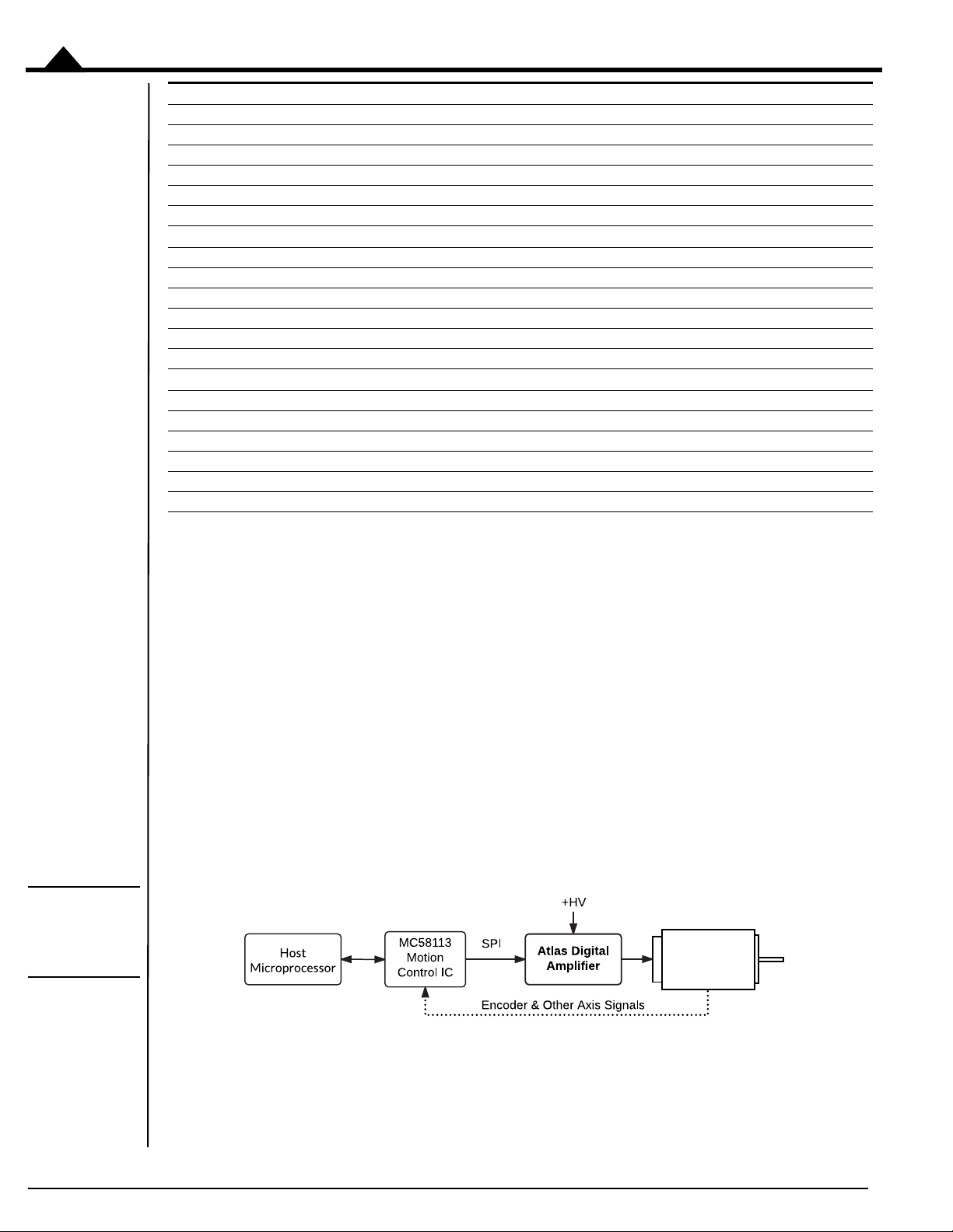
1.2.1 Single Axis Positioning Motion Controller
The diagram below shows a PMD MC58113 Motion Control IC sending torque commands to an Atlas Amplifier to
provide positioning control of a brushless DC, DC Brush, or Step Motor.
10 Atlas® Digital Amplifier Complete Technical Reference
Page 11
Introduction
Brushless DC,
DC Brush, or
Step Motor
Brushless DC,
DC Brush, or
Step Motor
Brushless DC,
DC Brush, or
Step Motor
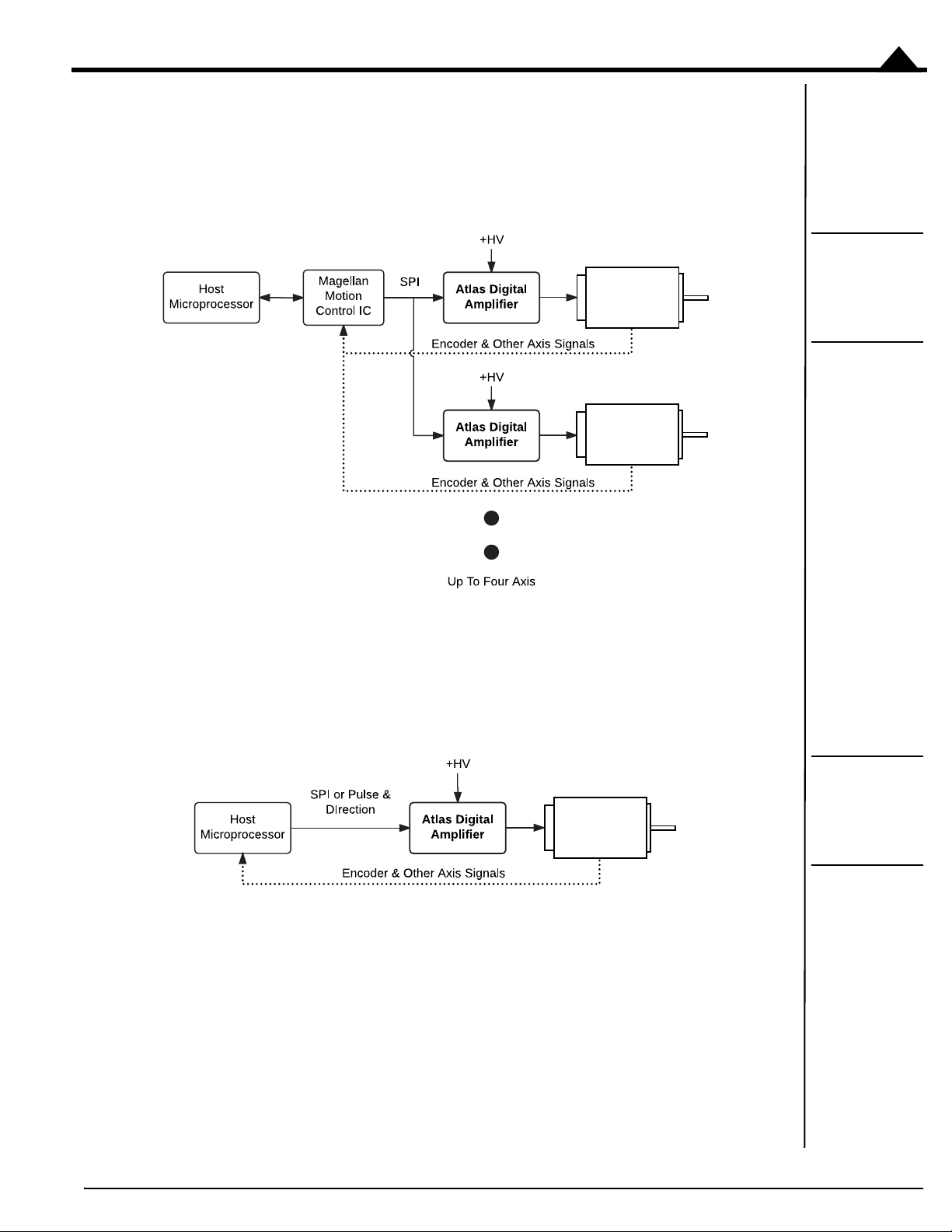
1.2.2 Multi Axis Positioning Motion Controller
The diagram below shows a PMD Magellan MC58000 series or MC55000 series multi-axis motion control IC being
used with two or more Atlas Amplifiers to provide control of brushless DC, DC Brush, or Step Motors in a
positioning application. If desired each axis can control a different motor type, so that, for example, brushless DC
motors can be used along with step motors in the same controller.
1
Figure 1-2:
Multi Axis
Magellan With
Atlas
Amplifiers
1.2.3 Microprocessor-Based Motion Controller
The diagram below shows the Atlas Amplifier being driven by a general purpose microprocessor that provides high
level path generation and servo loop closure and outputs continuous desired torque commands or desired position
increments for step motors to the Atlas Amplifier via the SPI (Serial Peripheral Interface).
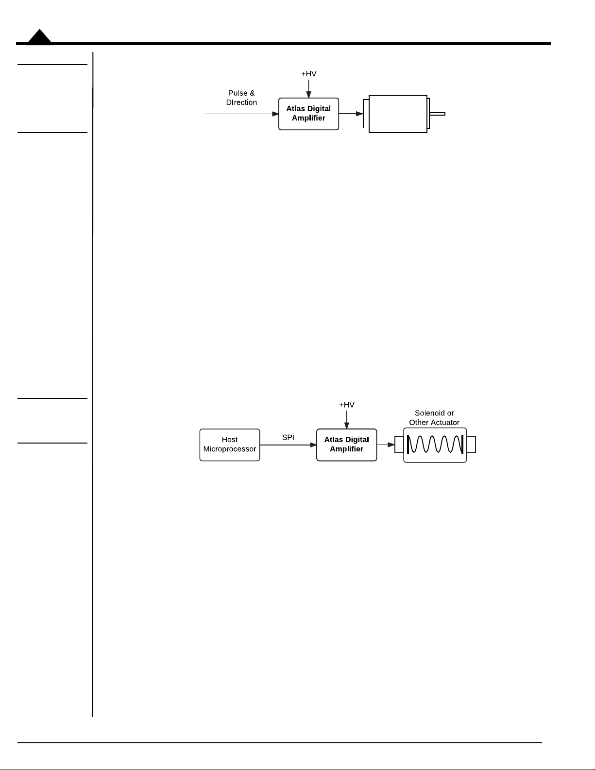
1.2.4 Stand Alone Step Motor Amplifier
iagram below shows the Atlas Amplifier being directly driven by pulse & direction signals. These signals may
The d
come from a microprocessor, a control card, or any other existing motion control device that outputs pulse & direction
signals. In this mode the Atlas unit operates ‘stand-alone,’ and utilizes configuration control parameters previously
stored into the Atlas unit’s NVRAM (non-volatile) memory.
Figure 1-3:
Direct Host
Microprocessor
With Atlas
Amplifiers
Atlas® Digital Amplifier Complete Technical Reference
11
Page 12
Introduction
Step Motor
1
Figure 1-4:
Direct Host
Microprocessor
With Atlas
Amplifiers
There are a few options for configuring Atlas units for stand alone operation:
• Pro-Motion can be used with the Atlas Developer’s Kit to program Atlas units
• The user can develop their own NVRAM programming system by utilizing the SPI (Serial Peripheral
Interface) Atlas command protocol. For more information refer to the Atlas® Digital Amplifier
Complete Technical Reference.
• PMD offers custom pre-configured Atlas units. For more information contact your local PMD sales
representative.
1.2.5 Force Control
The Brushless DC and DC Servo Atlas units can be used for general purpose force control applications such as remote
teleoperation, force feedback, solonoid actuation, and any other general purpose valve/actuator control where a
precisely controllable current is needed.
Figure 1-5:
Atlas Force
Control
In this application the torque command may be sent continuously by the host microprocessor or from time to time as
required by the application. In either case the Atlas provides very accurate current/torque control resulting in smooth
and precise application of force.
1.3 Features and Functions
The Atlas family of amplifiers provide an extensive list of functions, including:
• Available in Brushless DC, DC Brush, Step Motor, and multi-motor motor types
• High performance all-digital power amplifier
• Works with Magellan ICs, FPGAs or microprocessor-based controllers
• Digital SPI interface eliminates analog +/- 10V signals
• Available in 75W, 250W, and 500W+ power levels
• Rugged plastic solderable module format uses standard through-hole pins
• Total power output to 1Kilowatt
• Available in ultra compact 1.05" x 1.05" x .53" (27mm x 27mm x 13mm) size or compact 1.52" x 1.52"
x .60" (39mm x 39mm x 15mm) size
12 Atlas® Digital Amplifier Complete Technical Reference
Page 13

• Horizontal and vertical mount configurations
• Includes rugged mechanical tab mounts
• Supply voltage range of 12V up to 56V
• High current output up to 14A continuous, 25A peak
• Digital current loop with choice of standard A/B or Field Oriented Control (FOC)
• Direct signal pulse and direction input
2
•I
t current foldback limiting
Introduction
1
• Overcurrent, overvoltage, undervoltage, overtemperature, and SPI command watchdog time
protection
Single DC supply operation.
•
• Enable input and FaultOut output safety interlock signals
• SPI (Serial Peripheral Interface) up to 8 MHz
• Performance trace of up to 1,020 words and four simultaneous variables
• 1,024 word non-volatile parameter storage
• Microstepping control with up to 256 microsteps per full step
• Signal conditioning buffers and analog filters on all I/O signals
• Fully RoHS compliant and CE marked
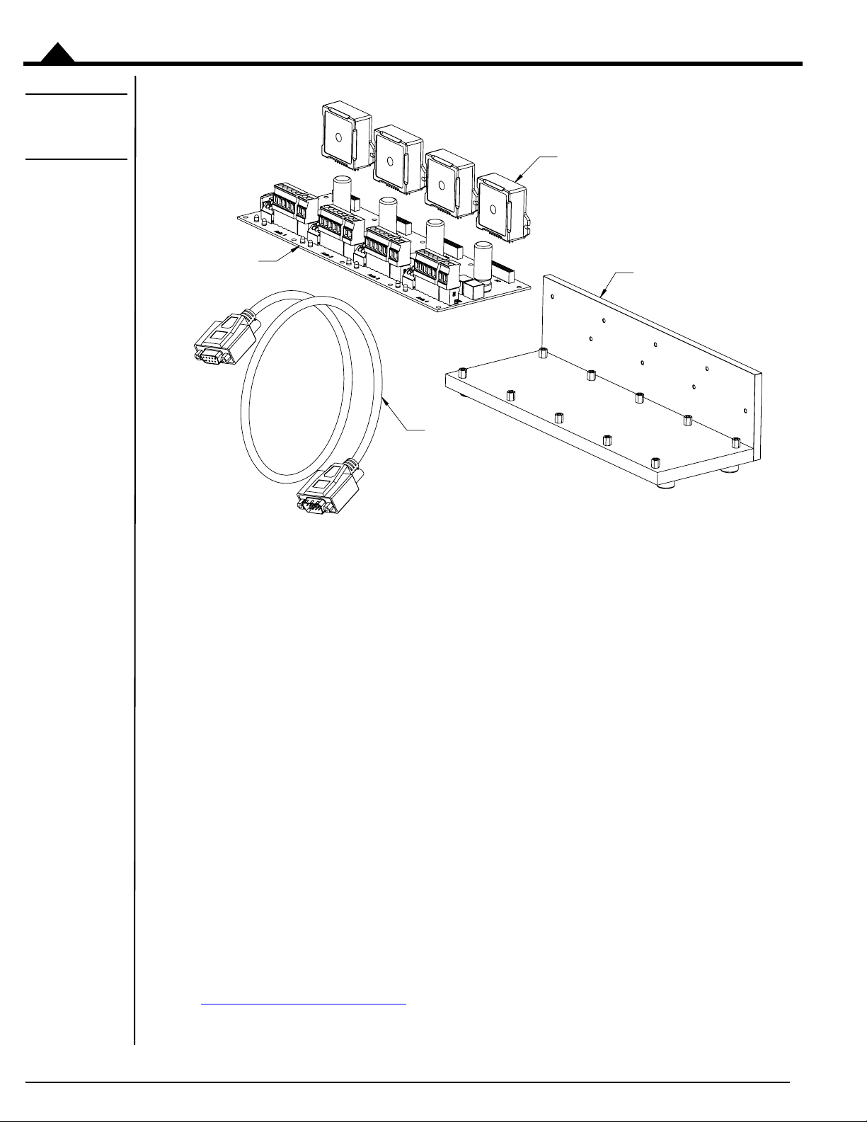
1.4 Atlas Developer’s Kit
To simplify development, an Atlas Developer’s Kit is available, shown in Figure 1-6.
out
Atlas® Digital Amplifier Complete Technical Reference 13
Page 14
Introduction
1
Figure 1-6:
Developer Kit
Components
The following software and hardware components are included in every Atlas Developer’s Kit:
• Pro-Motion CD and User’s Guide
• C-Motion and VB-Motion SDK CD, including PDFs of all Atlas documentation
• Atlas DK DB9 communications cable
For the following components, you will provide information that will specify how you want the DK tailored for your
exact development needs:
• Specific Atlas units to be included (motor type, power level)
• Atlas carrier card (horizontal or vertical, 1 or 4 axis version)
The carrier cards are designed for direct use with the compact Atlas format. For each ultra compact Atlas ordered a
converter card is provided that allows the ultra compact Atlas to be plugged into the compact carrier card socket
directly.
The L-bracket provides a stable mechanical base from which you can conveniently connect and operate your prototype
system motors. With the vertical plate, the Atlas units have additional heat sinking, which can be extended further by
connecting the vertical plate to your own heat sink or cold plate.
Electrical connection to the Atlas DK carrier card is made by DB9 connector, and by jack screw connectors. Designers
who plan to use the Atlas in conjunction with PMD’s Magellan Motion Control ICs can connect the Atlas DK to the
Magellan DK card, purchased separately. For more information on this product see one of the available Magellan
Motion Control IC developer’s kit user’s manuals.
Refer to Appendix A, “
Atlas DK.
Atlas Developer’s Kit” for complete information on ordering, setting up and operating the
14 Atlas® Digital Amplifier Complete Technical Reference
Page 15

2.Functional Characteristics
In This Chapter
Operational Specifications
Physical Dimensions
Mechanical Mounting Options
2.1 Operational Specifications
Operating Parameter Value
Motor types supported: Brushless DC, DC Servo, Step Motor
Communication format: SPI (Serial Peripheral Interface)
SPI clock frequency range: 2.0 MHz to 8.0 MHz
Torque command rate: up to 9.7 kHz
Current measurement resolution: 12 bits
Current loop type: P, I (proportional, integral) with Integral limit
Current loop resolution: 16 bits
Current loop rate: 19.530 kHz
Current loop modes: individual phase, field oriented control, third leg floating
Safety functions: over current detect, programmable over temperature
detect, programmable overvoltage detect, programmable
under voltage detect, programmable I
SPI command watchdog timeout
Output limiting:
Command modes: SPI voltage, SPI torque, pulse & direction signal
PWM rate: 20 kHz, 40 kHz, 80 kHz, or 120 kHz
PWM generation modes: sinusoidal, space vector modulation, standard single-phase
Pulse & direction rate: 1.0 M Pulses/sec
Microsteps per full step: up 256 per full step
Trace capture modes: one time, rolling-buffer
Trace trigger modes: internal clock, external by controller
Trace buffer size: 1,020 16-bit words
NVRAM storage size: 1,024 16-bit words
Programmable I2t energy, current, and voltage limit
2
t current foldback,
2
Atlas® Digital Amplifier Complete Technical Reference
15
Page 16
Functional Characteristics
2
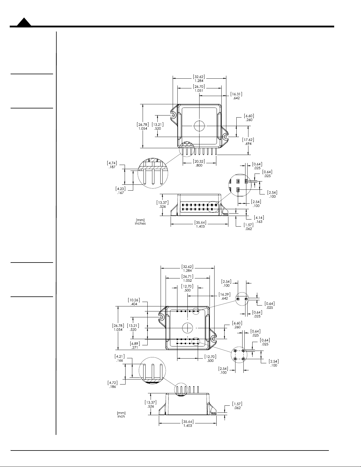
Figure 2-1:
Vertical Unit Ultra Compact
Package
2.2 Physical Dimensions
2.2.1 Vertical Unit, Ultra Compact Package
Figure 2-2:
Horizontal Unit
- Ultra Compact
Package
2.2.2 Horizontal Unit, Ultra Compact Package
16 Atlas® Digital Amplifier Complete Technical Reference
Page 17
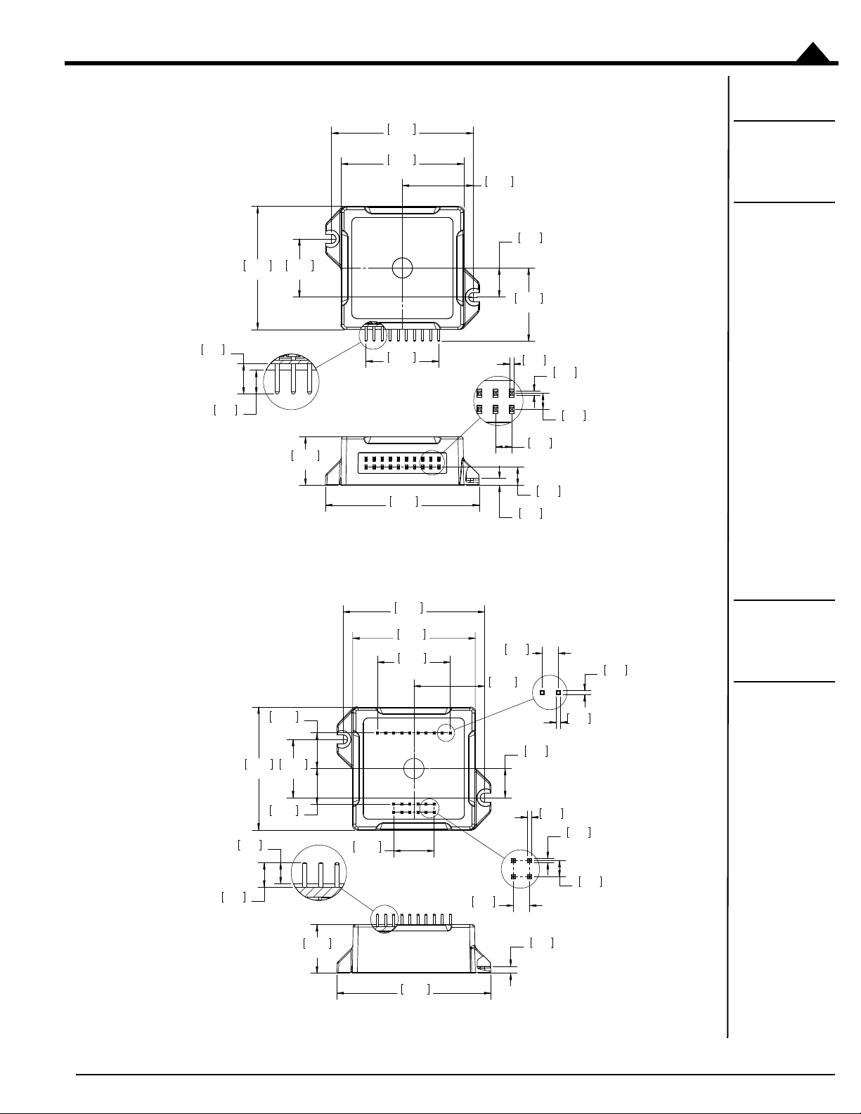
2.2.3 Vertical Unit, Compact Package
Functional Characteristics
Figure 2-3:
Vertical Unit Compact
Package
2
2.2.4 Horizontal Unit, Compact Package
Figure 2-4:
Horizontal Unit
- Co
mpac
Package
Atlas® Digital Amplifier Complete Technical Reference 17
t
Page 18

Functional Characteristics
2
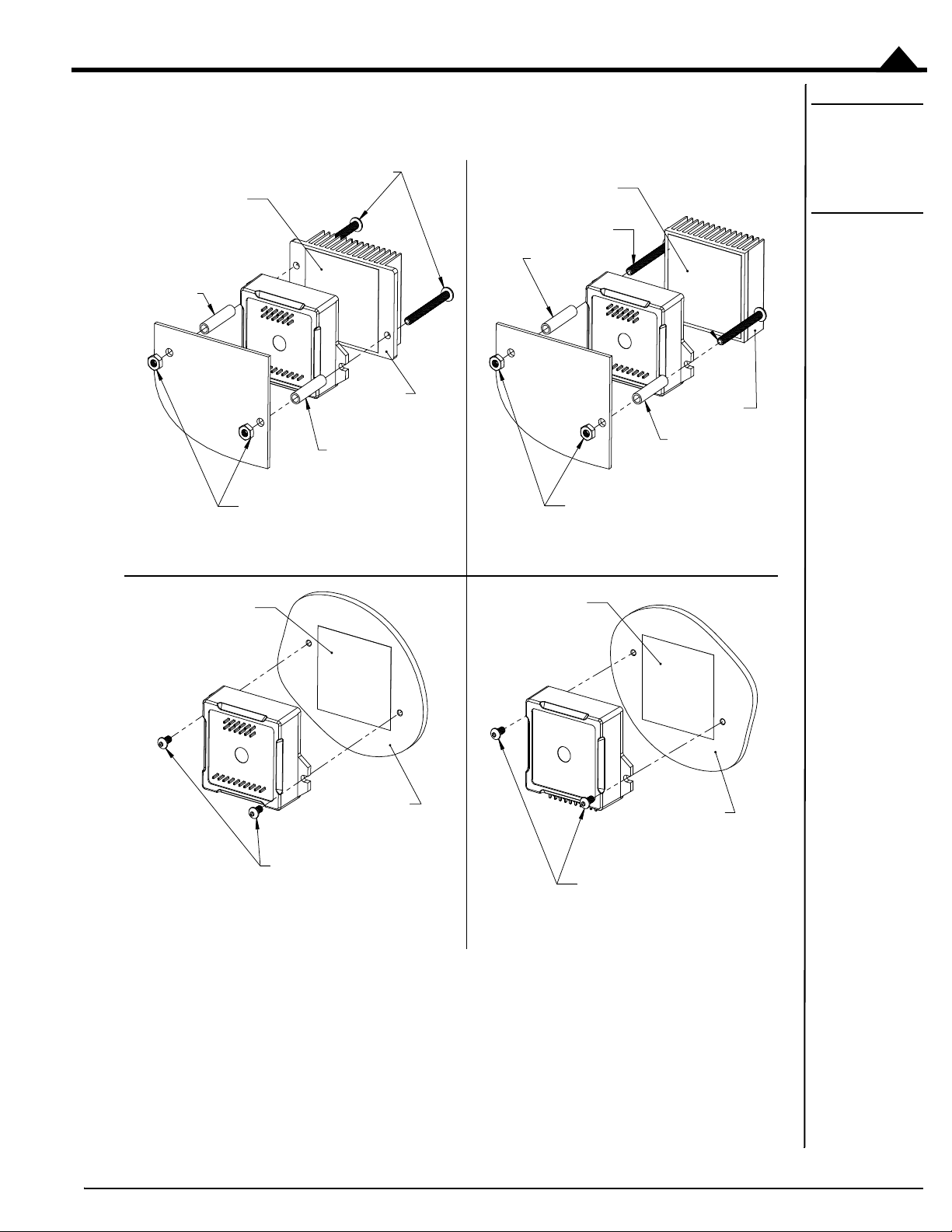
2.3 Mechanical Mounting Options
Atlas amplifiers are provided in two separate package sizes, ultra compact and compact, and in two separate mounting
configurations; vertical and horizontal. There are some very low power applications where the Atlas unit may be
mounted without mechanical attachment to the screw tabs. In such cases mechanical attachment to the PCB occurs
via the electrical solder connections.
Most applications however will utilize the Atlas unit’s integral screw tab mounts to rigidly connect the Atlas to the
PCB, to a heat sink, or to some other mechanical support. As shown in Figure 2-5 there are a number of Atlas
mounting options available when using the Atlas screw tabs. The choice of the mounting hardware depends on the
demands of the application.
The following table provides information related to the mechanical screw tab mounts:
Maximum
Recommended
Atlas Package
Ultra Compact M2.0 4.2 mm 2.2 mm
Compact M2.5 5.4 mm 2.8 mm
screw type
screw head
diameter
Maximum
screw body
diameter
18 Atlas® Digital Amplifier Complete Technical Reference
Page 19
Functional Characteristics
SCREWS (M2.0 or M2.5)
HEX NUT (M2.0 or M2.5)
STANDOFF
STANDOFF
HEAT SINK
HEAT SINK
SCREWS (M2.0 or M2.5)
HEX NUT (M2.0 or M2.5)
STANDOFF
STANDOFF
Vertical Unit, Mechanical Mount to Support/Cold Plate
SCREWS (M2.0 or M2.5)
SUPPORT/COLD
PLATE
SCREWS (M2.0 or M2.5)
Horizontal Unit, Mechanical Mount to Support/Cold Plate
Horizontal Unit, Mechanical Mount Through Heat Sink to PCB
THERMAL
TRANSFER
MATERIAL
THERMAL
TRANSFER
MATERIAL
THERMAL
TRANSFER
MATERIAL
THERMAL
TRANSFER
MATERIAL
SUPPORT/COLD
PLATE
BA
DC
Horizontal Unit, Mechanical Mount to PCB
Figure 2-5:
Horizontal &
Vertical Unit
Mounting
Options
2
2.3.1 Mounting Guidelines
Atlas amplifiers, while designed to be robust and easy to install, contain active electronics that can only function
reliably when the mechanical integrity and operating environment of the Atlas is maintained. The next three sections
Atlas® Digital Amplifier Complete Technical Reference
19
Page 20
Functional Characteristics
2
provide important recommendations and guidelines for the configuration, selection, placement, mounting method,
and installation procedure for Atlas amplifiers.
Choice of vertical or horizontal Atlas. The horizontal configuration of Atlas is recommended for applications where the
Atlas is not mechanically mated to a supporting plate and where vibration or movement-related forces may be present.
When the Atlas unit is mechanically mated to a supporting plate, either the horizontal or the vertical configuration
may be used. Figure 2-5
Attaching Atlas to a supporting plate. Some Atlas applications will utilize a supporting plate for heat removal or for
enhanced mechanical stability. For Atlas installations that may be subject to vibration or movement-related forces and
that utilize a supporting plate, special care should be taken to insure that there is no movement between the circuit
card that the Atlas is soldered or socketed to and the supporting plate which the Atlas is mechanically attached to. Such
movement could result in damage to the Atlas unit, the circuit card, or the supporting plate.
Attaching Atlas to a free-standing heatsink. Some Atlas applications will utilize a free standing heat sink, such as is shown
in Figure 2-5
recommended for use with vertical Atlas units. When mounting Atlas units with free standing heat sinks special care
should be taken where vibration or movement-related forces may be present. These forces, acting on the additional
mass of the heat sink, may impart excessive mechanical stress on the Atlas resulting in damage to the Atlas unit, the
circuit card, or the heat sink. Depending on the nature and magnitude of the forces, in these applications mounting
the Atlas to a supporting plate may be preferred.
Choice of socket or solder connection to the circuit card. For best electrical contact to the printed circuit board (PCB),
connection by soldering to the Atlas is generally recommended. This is particularly true for Atlas units that are not
mated to a supporting plate. When the Atlas unit is mounted to a supporting plate either solder or socket electrical
connections may be used, with solder connections recommended for applications benefitting from rigid connection
of the Atlas to the PCB, and sockets being recommended when greater mechanical isolation of the PCB from the
mechanical support is desired.
C and Figure 2-5D show the Atlas unit mechanically mated to a supporting plate.
A and Figure 2-5B. Free standing heat sinks are recommended with horizontal Atlas units but are not
Some of the electrical ratings of the Atlas may not be achievable when electrical connection to the Atlas is via
sockets rather than via soldering. It is the responsibility of the user to determine whether a particular motor output current and voltage rating may be achieved with a given socket.
2.3.2 Thermal Transfer Materials
Thermal transfer materials in the form of thermal tape, pads, paste, or epoxy may be used to improve thermal transfer
between the Atlas’ metal plate and an attached heat sink or supporting plate. These materials improve thermal
conductivity by filling in air gaps that form when two metallic surfaces are mated.
Figure 2-5
surface. The following guidelines may be helpful in selecting and sizing the thermal transfer material best-suited to
your application.
The capacity of thermal transfer materials to transfer heat (known as the bulk conductivity) is much lower than that
of metals such as aluminum or copper. Therefore, in general, the thinner the transfer material the better. Thickness of
the material is only precisely controllable for thermal pads and thermal tapes, with thermal pads providing the thinnest
available interfaces beginning at 5 mils (.127 mm) or even less. For use with Atlas amplifiers thermal transfer materials
that are thicker than 40 mils (1.0 mm) are not recommended regardless of the material used.
When using thermal paste or thermal epoxy glue the thickness should be carefully controlled via a silk screen or other
wet film application process. The Atlas unit itself should not be used to squeeze non-uniformly applied paste or epoxy
flat during installation. Doing so may result in damage to the Atlas.
shows a typical application of a thermal transfer material between the Atlas and a heat-removing metal
20 Atlas® Digital Amplifier Complete Technical Reference
Page 21

Functional Characteristics
1.40”
(35.6)
1.50”
(38.1)
1.00”
(25.4)
.95”
(24.1)
2
Whether using tape, pads, paste, or epoxy, as shown in Figure 2-6
, the thermal transfer material that is used as the
interface should not extend to the area under the Atlas’ tabs because this may reduce the amount of compression that
occurs in the thermal transfer area. The following table provides dimensions for the applied thermal transfer material
for the two available Atlas package sizes:
Maximum Pad
Atlas Package Size
Ultra Compact .1.00" x .95" (25.4 mm x 24.1mm)
Compact 1.40" x 1.50" (35.6 mm x 38.1
Dimensions
mm)
Figure 2-6:
Recommended
Atlas Unit
Thermal
Transfer
Material
Dimensions
2.3.3 Atlas Installation
There are a number of precautions and procedures that should be followed to maintain the electrical and mechanical
integrity of the Atlas unit during installation.
Soldering Atlas units in place. Applications that utilize Atlas units that are not mechanically mated to a heat sink or that
are mated to a self-standing heat sink may utilize a standard soldering process without special precautions or
procedures. Applications that involve Atlas units mated to a supporting plate and that will be soldered to the PCB
should take special care to insure that the solder joints are not stressed by the supporting plate once installed. The
recommended method to achieve this is to mechanically mate the Atlas to the supporting plate before soldering the
Atlas into the PCB. If, for whatever reason, this is not possible, then special care should be taken to insure that the
Atlas is precisely aligned with the supporting plate after soldering and before mechanical attachment so that upon
mechanical attachment no stress is placed on the Atlas unit, the solder contacts, or the PCB.
Mounting surface flat and clean. Thermal performance as well as safe operation of the Atlas requires that the surface that
the Atlas is mounted to be flat and clean, free of dust, grease, or foreign objects. The recommended maximum
deviation of the mating surface flatness is 3 mils (.076 mm).
Mechanical mounting limits. Applications that will utilize a mechanical attachment to the Atlas via the Atlas’s mounting
tabs should take special care not to overstress the mechanical tabs. Regardless of the attachment method, which is most
commonly screws but may also be clips or inserts, the linear force applied to each mechanical tab should not exceed
certain values as shown in the following table and the accompanying Figure 2-7
Maximum Direct Force
Atlas Package Size
Ultra Compact 25 pounds (111 N) M2.0 x .40, 11.0oz-in (.078 N-m)
Compact 35 pounds (156 N) M2.5 x.45, 12.5oz-in (.088 N-m)
Per Tab
Screw Type, Corresponding
Maximum Rotary Torque
.
Atlas® Digital Amplifier Complete Technical Reference 21
Page 22
Functional Characteristics
11.0 Oz-in (.078 N-m) - Ultra Compact Package
12.5 OZ-in (.088N-m) - Compact Package
M2.0 or M2.5 Screw
2
Figure 2-7:
Atlas Torque
Specifications
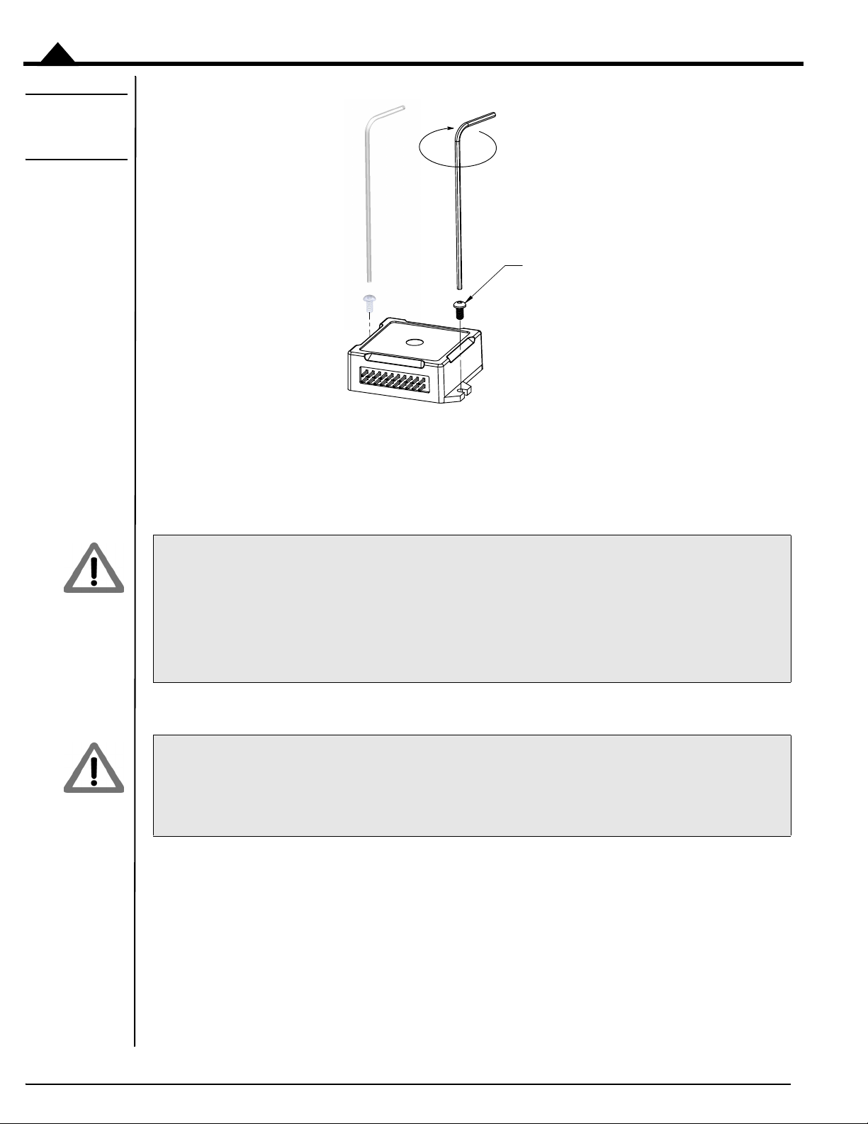
Mechanical mounting procedure. Atlas units that are mated to a heat sink or mechanical plate should be attached by
progressively tightening both of the Atlas unit’s tabs. This means that one screw may be tightened, followed by the
other, than back to the first etc. until the desired torque at each screw has been achieved. Following this procedure is
particularly important when installing Atlas units over paste or epoxy, where the subsurface layer will undergo
compression and movement before settling to a final installed position.
To ensure that proper contact exists between the Atlas and the entire thermal transfer material substrate, and to
ensure that the Atlas unit is not damaged via mechanical overstress, the user should carefully apply equal torque
increments to each tab screw, never exceeding at any point the torque limit on either tab of 25 lbs (111 N) linear
force or 11.0 oz-in (.078 N-m) rotary torque using a M2.0 x .40 screw for the ultra compact Atlas package, and
35 lbs(156N) linear force or 12.5oz-in (.088 N-m) rotary torque using a M2.5 x .45screw for the compact Atlas
package.
.
It is the responsibility of the user to ensure that all Atlas units have been installed within the above prescribed
mechanical stress limits and following the above described procedures. Failure to observe any of the above recommended procedures and limits may result in incorrect operation or failure of the Atlas during operation.
22 Atlas® Digital Amplifier Complete Technical Reference
Page 23

3.Electrical Specifications
In This Chapter
Drive Ratings
Absolute Maximum Ratings
Environmental Ratings
Safety and Compliance
DC Characteristics
AC Characteristics
Pin Descriptions and Pinouts
Signal Interfacing
Connection Overview
Heat Sink Grounding
Atlas Conversion Factors
3.1 Drive Ratings
3.1.1 Low Power Units (P/Ns MD2x1048/02xB)
3
Specifications
Nominal supply voltage 12-48 VDC 12-48 VDC 12-48 VDC
Continuous current 1.5 ADC 1.5 Arms 1.5 Arms
Peak current (per phase) 3.8 A 3.8 A 3.8 A
Maximum continuous power 72 W 88 W 102 W
*
transformer isolated power supply, T < 40° C
A coldplate or a heatsink in an environment with sufficient airflow can be used to achieve the above drive ratings.
For temperature operation beyond the standard 0-40° C range, above-listed ratings may change. Contact your PMD
representative for additional information on Atlas extended temperature operation including higher temperature drive
ratings.
*
DC Brush
Motor
Brushless DC
Motor
Step
Motor
3.1.2 Medium Power Units (P/Ns MD2x1048/05xB)
Specifications
Nominal supply voltage 12-48 VDC 12-48 VDC 12-48 VDC
Continuous current 7.0 ADC 5 Arms 4.5 Arms
Peak current (per phase) 12.5 A 12.5 A 12.5 A
Maximum continuous power 336 W 294 W 305 W
*
DC Brush Motor Brushless DC Motor Step Motor
Atlas® Digital Amplifier Complete Technical Reference
23
Page 24
Electrical Specifications
3
*
transformer isolated power supply, T < 40° C
A coldplate or a heatsink in an environment with sufficient airflow can be used to achieve the above drive ratings.
For temperature operation beyond the standard 0-40° C range, above-listed ratings may change. Contact your PMD
representative for additional information on Atlas extended temperature operation including higher temperature drive
ratings.
3.1.3 High Power Units (P/Ns MD2x1056/25xB)
Specifications
Nominal supply voltage 12-56 VDC 12-56 VDC 12-56 VDC
Continuous current 14.0 ADC 10.0 Arms 9.0 Arms
Peak current (per phase) 25.0 A 25.0 A 25.0 A
Maximum continuous power 670 W 590 W 610 W
*
transformer isolated power supply, T < 40° C
*
DC Brush Motor Brushless DC Motor Step Motor
A coldplate or a heatsink in an environment with sufficient airflow can be used to achieve the above drive ratings.
For temperature operation beyond the standard 0-40° C range, above-listed ratings may change. Contact your PMD
representative for additional information on Atlas extended temperature operation including higher temperature drive
ratings.
3.2 Absolute Maximum Ratings
Parameter Rating
HV voltage range, low power units 0 V to +52 V
HV voltage range, medium power units 0 V to +52 V
HV voltage range, high power units 0 V to +60 V
~Enable voltage range -10 V to +24 V
SPISI, SPIClk, ~SPICS voltage range -0.5 V to 6.5 V
SPISO voltage range -0.5 V to 3.7 V
FaultOut voltage range -0.3 V to 24 V
FaultOut output current -35 uA to 50 mA
5V output current, low power units 50 mA
5V output current, medium power units 50 mA
5V output current, high power units 100 mA
All voltage values are with respect to GND unless otherwise noted.
24 Atlas® Digital Amplifier Complete Technical Reference
Page 25

3.3 Environmental Ratings
Specification Value
Operating ambient temperature 0 to 40 C
Maximum base plate temperature 75 C
Storage temperature -20 to 85 C
Reflow soldering temperature 300 C (1.5mm for 10 seconds)
Humidity 0 to 95%, non-condensing
Altitude Up to 2,000 meters without derating
Contamination Pollution Degree 2
3.4 Safety and Compliance
Specification Standard
CE LVD: EN60204-1
EMC-D: EN61000-6-1, EN61000-6-3, EN55011
Electrical safety Designed to UL508C, UL840 and EN60204-1
Hazardous materials RoHS compliant
Flammability UL94-HB
Enclosure IP20
Electrical Specifications
3
3.5 DC Characteristics
3.5.1 SPISI, SPIClk
Schmitt-trigger Input Min Max Conditions
, Positive-going input threshold voltage 1.6 V 2.0 V
V
+
V-, Negative-going input threshold voltage 0.9 V 1.2 V
VT, Hysteresis V+-V- 0.6 V 1.0 V
, input current ±1 uA Input voltage is 5.5 V or GND
I
IN
3.5.2 SPISO
Min Max Conditions
, output voltage 0 3.3 V
V
O
, Logic 1 output voltage 3.2 V IOH=-100 uA
V
OH
2.4 V I
, Logic 0 output voltage 0.1 V IOL=100 uA
V
OL
0.7 V I
I
, input current when ~SPICS is “1” 10 uA VO = 0 to 3.7 V
OZ
=-16 mA
OH
=16 mA
OL
Atlas® Digital Amplifier Complete Technical Reference 25
Page 26

Electrical Specifications
3
3.5.3 ~SPICS
, Logic 1 input voltage 2 V
V
IH
, Logic 0 input voltage 0.8 V
V
IL
, pull-up current -500 uA
I
IN
3.5.4 ~Enable
Schmitt-trigger input Min Max Conditions
V+, Positive-going input threshold voltage 1.6 V 2.0 V
V-, Negative-going input threshold voltage 0.9 V 1.2 V
VT, Hysteresis V+-V- 0.6 V 1.0 V
3.5.5 FaultOut
Output impedance with Logic 1 output 148 Kohm 152 Kohm I
, Logic 0 output voltage 0.25 V IOL=10 mA
V
OL
Min TYP Max Conditions
Min Max Conditions
=-100 uA
OH
3.5.6 5V
Min Max Conditions
Voltage tolerance, low power units -5% 5% Output current 0-50 mA
Voltage tolerance, medium power units -5% 5% Output current 0-50 mA
Voltage tolerance, high power units -5% 5% Output current 0-100 mA
Short circuit protection Not available
26 Atlas® Digital Amplifier Complete Technical Reference
Page 27
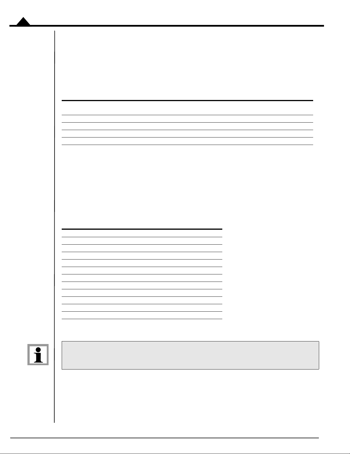
3.6 AC Characteristics
SPISI
SPISO
SPIClk
~SPICS
T1
T3
T2
T5 T6
data is valid
data
must be valid
T8
T4
T9
T7
Electrical Specifications
Figure 3-1:
Timing
Diagrams
3
See Figure 3-1
Timing Interval No. Min Max
, SPI clock cycle time T1 125 nsec
T
SPI
Pulse duration, SPIClk high T3 (0.5 T
Pulse duration, SPIClk low T4 (0.5 T
SPIClk high to SPISO valid delay time T5 30 nsec
SPISO date valid time after SPIClk low T6 0 nsec
SPISI setup time before SPIClk low T7 30 nsec
SPISI valid time after SPIClk low T8 (0.5 T
~SPICS low to first SPIClk high T2 400 nsec
Last SPIClk low to ~SPICS high T9 0.5 T
for timing numbers.
-10) nsec
SPI
-10) nsec
SPI
-6) nsec
SPI
SPI
3.7 Pin Descriptions and Pinouts
Atlas units regardless of package size or mounting configuration provide a common set of signals and functions
All
however the pin addresses and number of pins for various functions are different between the ultra compact Atlas
units and the compact Atlas units. In addition, the pin addresses are different between the horizontal and vertical
mounting configurations for each package size.
The following sections provide detailed pinouts for the two Atlas packages; ultra compact and compact, and the two
mounting configuration; horizontal and vertical.
All Atlas unit pins are 0.1 inch spacing and 0.025inch pin width.
Atlas® Digital Amplifier Complete Technical Reference
27
Page 28
Electrical Specifications
18
16
14 12
10
8 6
4
17
15
13 119 7 5
3
1
6 5 4321
17 15 13 11 9 7
18 16 14 12 10 8
3
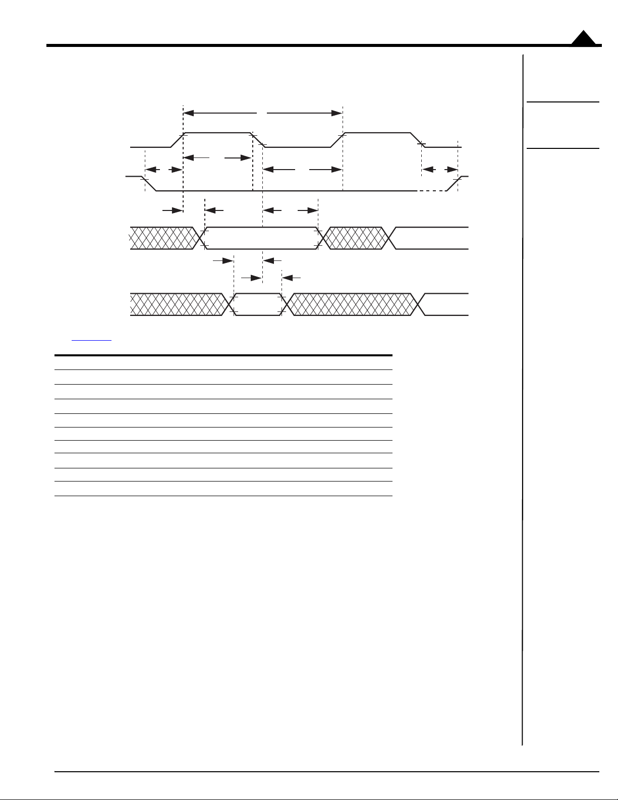
Figure 3-2:
Atlas Pinouts Ultra Compact,
Vertical
3.7.1 Atlas Pinouts - Ultra Compact, Vertical
Pin Name Pin Name
1HV 2
3Motor A 4Pwr_Gnd
5Motor C 6Motor B
7 Motor D 8 NC (No Connect)
9 NC (No Connect) 10 NC (No Connect)
11 ~Enable 12 FaultOut
13 GND 14 5V
15 SPISO 16 ~SPICS/AtRest
17 SPIClk/Pulse 18 SPISI/Direction
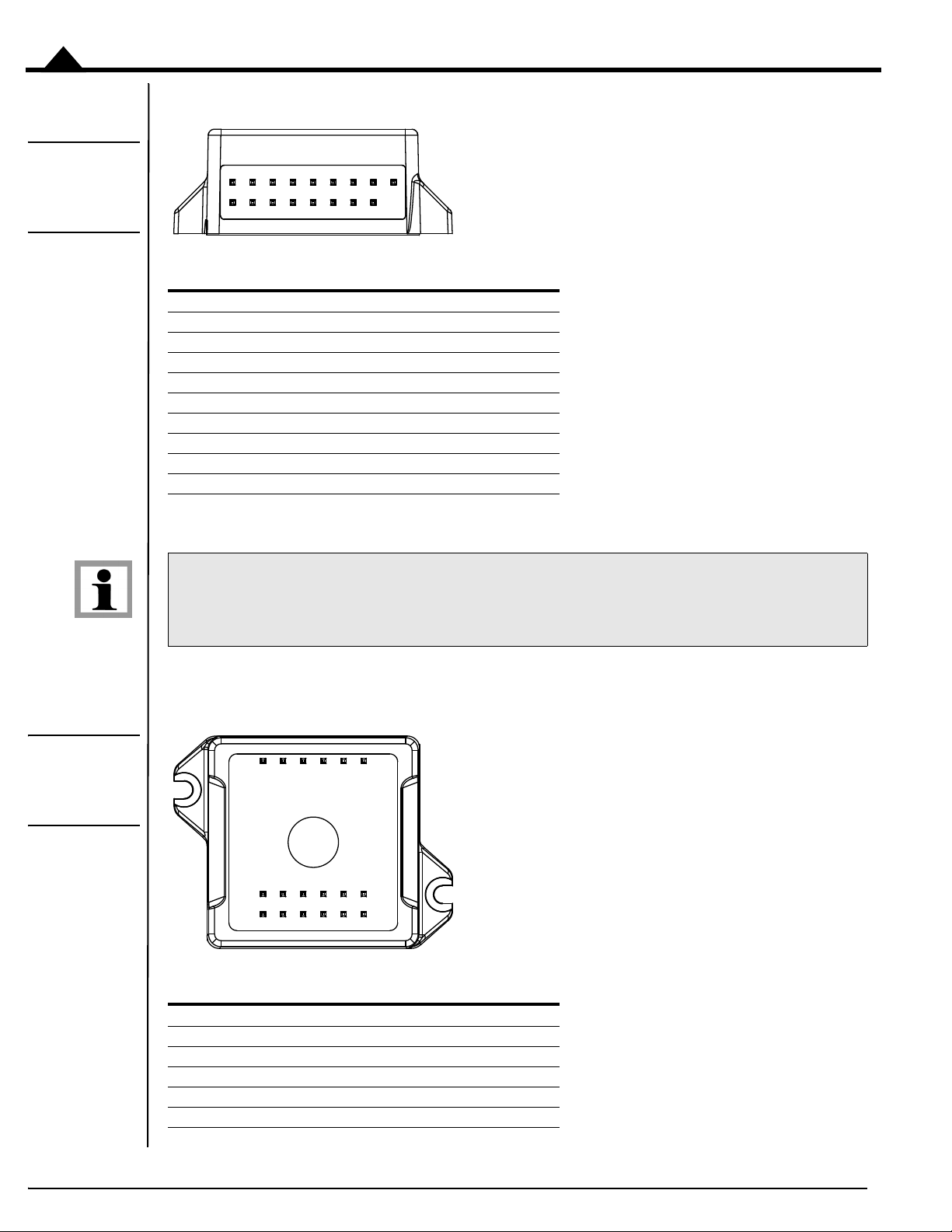
Figure 3-3:
Atlas Pinouts Ultra Compact,
Horizontal
The ultra compact Atlas vertical package is keyed so that it is installation direction dependent. It has no physical
pin installed at the Pin #2 location.
3.7.2 Atlas Pinouts - Ultra Compact, Horizontal
Pin Name Pin Name
1 Motor D 2 Motor C
3 Motor B 4 Motor A
5HV 6 Pwr_Gnd
7 SPISI/Direction 8 SPIClk/Pulse
9 SPISO 10 ~SPICS/AtRest
28 Atlas® Digital Amplifier Complete Technical Reference
Page 29
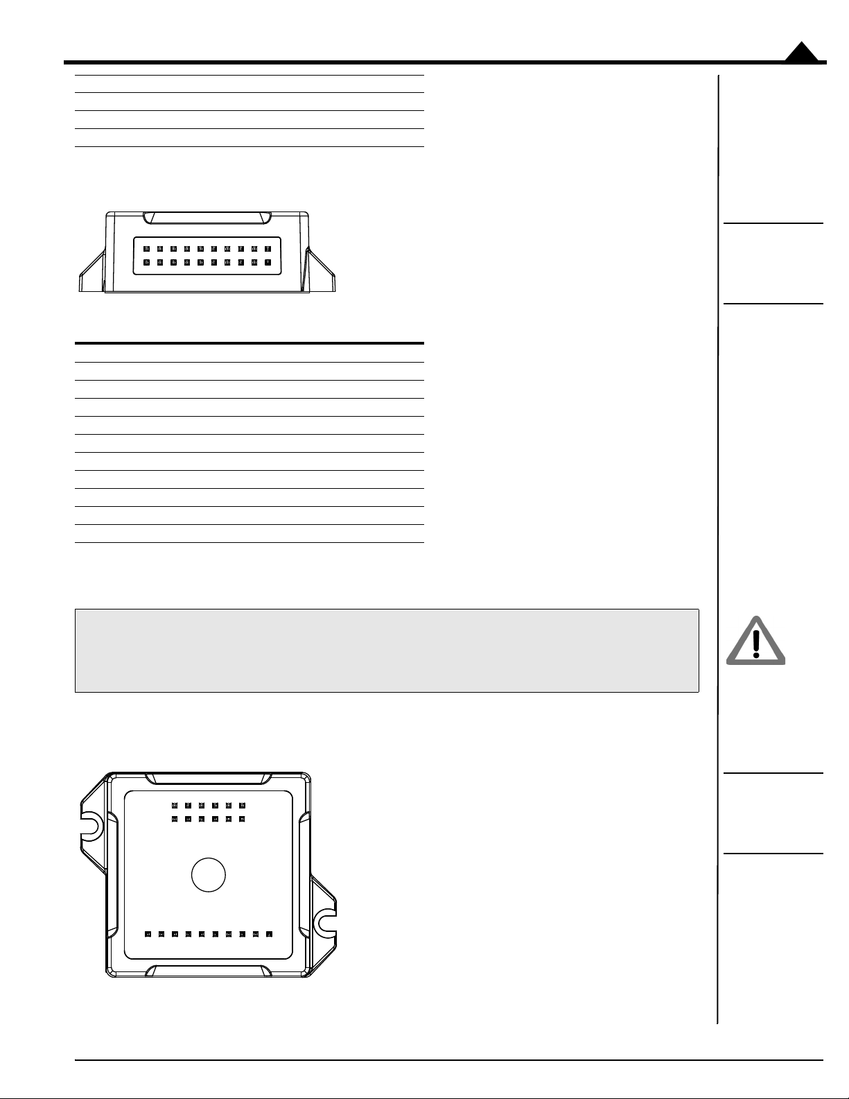
11 5V 12 GND
19
17 15
13 11 9 7 5 3 1
20
18
16 14
12 10 8 6
4
2
12
10 8
6
4 2
22 21 20 19
18
17 16 15 14 13
11
9
7 5
3
1
13 FaultOut 14 ~Enable
15 GND 16 NC (no connect)
17 NC (no connect) 18 NC (no connect)
3.7.3 Atlas Pinouts - Compact, Vertical
Pin Name Pin Name
1 Pwr_Gnd 2 Pwr_Gnd
3HV 4 HV
5 Motor A 6 Motor A
7 Motor B 8 Motor B
9 Motor C 10 Motor C
11 Motor D 12 Motor D
13 ~Enable 14 FaultOut
15 5V 16 GND
17 ~SPICS/AtRest 18 SPISI/Direction
19 SPIClk/Pulse 20 SPISO
Electrical Specifications
Figure 3-4:
Atlas Pinouts Compact,
Vertical
3
The compact Atlas package provides additional power output via doubling of the HV, Pwr_Gnd, and Motor output
pins. To achieve the rated unit power output be sure that both pins are connected.
The compact Atlas vertical package is not keyed and therefore care should be taken to install in the correct orientation.
3.7.4 Atlas Pinouts - Compact, Horizontal
Figure 3-5:
Atlas Pinouts Compact,
Horizontal
Atlas® Digital Amplifier Complete Technical Reference 29
Page 30

Electrical Specifications
3
Pin Name Pin Name
1 Motor D 2 Motor D
3 Motor C 4 Motor C
5 Motor B 6 Motor B
7 Motor A 8 Motor A
9HV 10 HV
11 Pwr_Gnd 12 Pwr_Gnd
13 5V 14 GND
15 ~Enable 16 FaultOut
17 GND 18 ~SPICS/AtRest
19 SPISO 20 SPISI/Direction
21 SPIClk/Pulse 22 GND
The compact Atlas package provides additional power output via doubling of the HV, Pwr_Gnd, and Motor output
pins. To achieve the rated unit power output be sure that both pins are connected.
3.7.5 Pin Descriptions
Pin Name Direction Description
HV DC power to Atlas module, referenced to Pwr_Gnd. The DC power source
Pwr_Gnd Power return for HV, Motor A, Motor B, Motor C and Motor D. For the compact
Motor A Motor output pin A. Used with Brushless DC, DC Brush, and Step Motors. For the
Motor B Motor output pin B. Used with Brushless DC, DC Brush, and Step Motors. For the
Motor C Motor output pin C. Used with Brushless DC, and Step Motors. For the compact
Motor D Motor output pin D. Used with Step Motors. For the compact Atlas package two
~Enable Input ~Enable is an active-low input. Should be tied or driven low for Atlas motor output
FaultOut Output FaultOut is high impedance when active. It provides programmable fault indication,
SPIClk/Pulse Input SPI input clock or Pulse signal.
SPISO Output SPI data master in slave out signal. It goes to high impedance when ~SPICS is high.
should be a transformer isolated power supply. For the compact Atlas package two
pins carry this signal, so care should be taken to connect both pins.
Atlas package two pins carry this signal, so care should be taken to connect both
pins. For greatest EMI protection double shielded cables on the motor winding A,
B, C, and D should be used with the inner shield connected to Pwr_Gnd and the
outer shield connected to chassis ground.
compact Atlas package two pins carry this signal, so care should be taken to connect both pins.
compact Atlas package two pins carry this signal, so care should be taken to connect both pins.
Atlas package two pins carry this signal, so care should be taken to connect both
pins.
pins carry this signal, so care should be taken to connect both pins.
to be active.
and is low when inactive.
Pulse is used when Atlas is set to pulse & direction signal mode, and causes a position change command upon a high to low transition. Selection of signal interpretation for this pin is via the SPI communications bus. The default signal interpretation
is SPIClk.
This pin is not used if Atlas is operating in pulse & direction signal mode.
30
Page 31

Electrical Specifications
Pin Name Direction Description
SPISI/Direction Input SPI data master out slave in signal or Direction signal.
Direction is used when Atlas is set to pulse & direction signal mode, and indicates
the step direction. Low means the position decreases upon a high to low transition
of the Pulse signal, and high means the position increases. Selection of signal interpretation for this pin is via the SPI communications bus. The default signal interpretation is SPISI.
~SPICS/AtRest Input ~SPICS signal or AtRest signal.
~SPICS enables SPI communication when transitioning low. The SPI block is disabled when ~SPICS is high.
AtRest is used when Atlas is set to pulse & direction signal mode, and indicates that
the step motor holding current should be used rather than the drive current.
Selection of signal interpretation for this pin is via the SPI communications bus. The
default signal interpretation is ~SPICS.
GND Ground return for ~Enable, FaultOut, SPI or pulse & direction signals and 5V.
5V 5V output used to drive external circuitry.
3
Atlas® Digital Amplifier Complete Technical Reference 31
Page 32

3
5V 5V
22k
5.6n
~Enable
10k
FaultOut
150k
5V
Q1
Figure 3-6:
Signal
Interfacing
~Enable
Electrical Specifications
3.8 Signal Interfacing
3.8.1 ~Enable
~Enable and FaultOut signals are typically used to implement a safety interlock between the Atlas module and other
portions of the system.
~Enable is an active low input that must be tied or driven low for the Atlas power output to be active. Its input buffer
is shown in Figure 3-6
thresholds. It has a pull-up to 5V to allow direct interfacing to open collector enable sources without external pull-up
resistor and a 1.3kHz R-C low-pass filter to reject noise.
. The circuit accepts signals in the range of 0-24V and has TTL compatible, Schmidt trigger
Figure 3-7:
Signal
Interfacing
FaultOut
3.8.2 FaultOut
FaultOut is asserted high when a fault occurs. The external controller can select which fault conditions drive the
FaultOut signal.
An Atlas FaultOut output circuit is shown in diagram Figure 3-7
low. It has a 150kohm pull-up resistor to 5V. Its voltage range is 0 to 24V.
. This circuit can continuously sink 50mA when pulled
32 Atlas® Digital Amplifier Complete Technical Reference
Page 33

3.9 Connection Overview
Enable FaultOut
Motor A
Motor B
Motor C
Optional Hall Sensors
Atlas
®
Digital
Amplifier
3 - Phase
Brushless
DC Motor
External
Controller
Optional
Optional Encoder Feedback
Hall & Encoder
SPI
SPICS
SPIClk
SPISI
SPISO
Pwr_Gnd
HV
3.9.1 Brushless DC Motors
Electrical Specifications
Figure 3-8:
Brushless DC
Connections
3
The following table summarizes the recommended connections when connecting Atlas amplifiers to brushless DC
motors
Optional
Type Required Connections
Connections
Power HV, Pwr_Gnd
Communication ~SPICS, SPISO, SPISI, SPIClk, GND
Motor Motor A, Motor B, Motor C
Miscellaneous ~Enable FaultOut
If Atlas is used as part of a higher level position controller, as shown in the Figure 3-8
, the Brushless DC motor
provides feedback signals to the external controller. Commonly, both Hall sensor signals and a position encoder are
used, but only one or the other is needed in a minimal configuration. In this configuration the external controller
generally consists of a PMD Magellan Motion Processor or a programmable microprocessor or DSP-type device.
Alternatively, Atlas can be operated by an external controller as a standalone device, driving the motor at commanded
voltage or torque levels and not part of a higher-level servo controller. In this configuration, the external controller
can be either a microprocessor-type device, or a logic device such as an FPGA (field programmable gate array).
Atlas functions as a power block providing amplification, current control, and safety management of the amplifier and
motor. Atlas does not directly accept Hall signals or encoder signals, so to operate with a brushless DC motor the
motor's current phase angle must be provided by the external controller through the SPI interface.
The Atlas does not support direct Hall signal inputs. To operate the Atlas with a Brushless DC motor, continuous
motor phase angle is provided by the external controller, via either Hall inputs or an encoder.
Atlas® Digital Amplifier Complete Technical Reference 33
Page 34

Electrical Specifications
Enable FaultOut
Optional Encoder Feedback
Encoder
Atlas
®
Digital
Amplifier
DC Brush
Motor
External
Controller
SPI
SPICS
SPIClk
SPISI
SPISO
Optional
Pwr_Gnd
HV
Motor A
Motor B
3
Figure 3-9:
DC Brush
Connections
3.9.2 DC Brush Motors
The following table summarizes the recommended connections when connecting Atlas amplifiers to DC Brush
motors.
Optional
Type Required Connections
Power HV, Pwr_Gnd
Communication ~SPICS, SPISO, SPISI, SPIClk, GND
Motor Motor A, Motor B
Miscellaneous ~Enable FaultOut
Connections
If Atlas is used as part of a higher level servo controller, as shown in Figure 3-9
, an encoder provides position or
velocity feedback signals to the external controller. In this configuration the external controller generally consists of a
PMD Magellan Motion Processor or a programmable microprocessor or DSP-type device.
Alternatively, Atlas can be operated by an external controller as a standalone device, driving the motor at commanded
voltage or torque levels. In this configuration the external controller can be either a microprocessor-type device, or a
logic device such as an FPGA (field programmable gate array).
34 Atlas® Digital Amplifier Complete Technical Reference
Page 35

Electrical Specifications
Enable
Pwr_Gnd
FaultOut
Optional Encoder Feedback
Encoder
Atlas
®
Digital
Amplier
2 - Phase
Step
Motor
External
Controller
Pulse
Direction
AtRest
Motor A
Motor B
Motor C
Motor D
HV
3.9.3 Step Motors in Pulse & Direction Signal Mode
The following table summarizes the recommended connections when connecting Atlas amplifiers to two-phase step
motors when using the pulse & direction signal mode. In this mode the external controller provides position
commands to Atlas via pulse and direction signals.
3
Figure 3-10:
Step Motor
Pulse and
Direction Mode
Connections
Optional
Type Required Connections
Connections
Power HV, Pwr_Gnd
Communication Pulse, Direction, GND AtRest
Motor, Phase A
Motor, Phase A
Motor, Phase B+:
Motor, Phase B-:
+
:
-
Motor A
Motor B
Motor C
Motor D
Miscellaneous ~Enable FaultOut
These connections apply to bipolar motors. If connecting to unipolar motors do not connect the center tap.
In this configuration the external controller generally consists of an off-the-shelf motion control card or module, a
programmable microprocessor or DSP-type device, or a FPGA (field programmable gate array). The external
controller provides a continuous stream of pulse and direction commands, along with (optionally) an
AtRest signal to
control the torque.
To initially set up and store its application-specific configuration parameters, Atlas is programmed using the SPI
interface and then commanded to convert to pulse & direction signal mode.
FaultOut signal input to external controller is strongly recommended when the Atlas is used in Pulse & Direction signal
mode.
Atlas® Digital Amplifier Complete Technical Reference 35
Page 36

Electrical Specifications
Enable FaultOut
Optional Encoder Feedback
Encoder
Atlas
®
Digital
Amplifier
2 - Phase
Step
Motor
External
Controller
SPI
SPICS
SPIClk
SPISI
SPISO
Optional
Motor C
Motor D
Pwr_Gnd
HV
Motor A
Motor B
3
Figure 3-11:
Step Motor
SPI Communication Connections
3.9.4 Step Motors Using SPI Communications
The following table summarizes the recommended connections when connecting Atlas amplifiers to two-phase step
motors when using the SPI communications channel. In this mode the external controller provides position
commands to Atlas via the SPI interface.
Optional Signal
Type Required Signal Connections
Connections
Power HV, Pwr_Gnd
Communication ~SPICS, SPISO, SPISI, SPIClk, GND
Motor, Phase A
Motor, Phase A
Motor, Phase B+:
Motor, Phase B
+
-
-
:
Motor A
:
Motor B
Motor C
Motor D
Miscellaneous ~Enable FaultOut
These connections apply to bipolar motors. If connecting to unipolar motors do not connect the center tap.
In this configuration the external controller generally consists of a PMD Magellan Motion Processor, a programmable
microprocessor or DSP-type device, or a FPGA (field programmable gate array). The external controller provides a
continuous stream of position commands or individual phase torque output commands to control the motor position.
3.10 Heat Sink Grounding
The heat sink may be left ungrounded or may be connected to chassis ground for best EMI protection. The heat sink
should not be connected to the Atlas Pwr_Gnd.
3.11 Atlas Conversion Factors
The following table provides electrical conversion factors for the various Atlas units. These factors convert Atlas
command values specified via the Atlas unit's digital SPI interface (referred to as counts) to physical quantities such
as amperage or volts, and vice versa. For more information on the Atlas functions related to these conversion factors
see Chapter 4,
36 Atlas® Digital Amplifier Complete Technical Reference
Operation.
Page 37

Electrical Specifications
3
Unit
All Low Power
Atlas
All Medium
Power Atlas
All High Power
Atlas Example Usage
Amps .231 mA/count .763 mA/count 1.526 mA/count To command a torque of 3.5A
to the high power Atlas a value
of 3,500mA/1.526mA/count =
2,294 counts is specified.
Volts 1.361 mV/count 1.361 mV/count 1.361 mV/count A command request to read the
Atlas unit’s DC Bus voltage gives
a value of 12,345. This corresponds to a voltage of 12,345
counts * 1.361 mV/count = 16.8
volts.
Temperature .0039°C/count
.0039°C/count
.0039°C/count A command request to read the
Atlas unit’s internal temperature
gives a value of 7,890. This corresponds to a temperature of
7,890 counts * .0039°C/count =
30.8°C.
Foldback Energy
.0059 A
2
sec/count .064 A2sec/count .256 A2sec/count
To command a foldback energy
2
sec to the high power
of 50A
Atlas a value of 50A
2
sec/.256
A2sec/count = 195 counts is
specified.
3.11.1 Atlas Settings Defaults and Limits
The following table provides default and limit values for all Atlas units.
All Low
Quantity
Power Atlas
Overtemperature
Overtemperature Limit Default: 75.0°C Default: 75.0°C Default: 75.0°C
Low Limit: 0 Low Limit: 0 Low Limit: 0
High Limit: 75.0°C High Limit: 75.0°C High Limit: 75.0°C
Overtemperature Hysteresis Default: 5.0°C Default: 5.0°C Default: 5.0°C
Low Limit: 0 Low Limit: 0 Low Limit: 0
High Limit: 25.0°C High Limit: 25.0°C High Limit: 25.0°C
Voltage
Overvoltage Limit Default: 52.0 V Default: 52.0 V Default: 60.0 V
Low Limit: 10.0 V Low Limit: 10.0 V Low Limit: 10.0 V
High Limit: 52.0 V High Limit: 52.0 V High Limit: 60.0 V
Undervoltage Limit Default: 10.0 V Default: 10.0 V Default: 10.0 V
Low Limit: 10.0 V Low Limit: 10.0 V Low Limit: 10.0 V
High Limit: 48.0 V High Limit: 48.0 V High Limit: 56.0 V
All Medium
Power Atlas
All High
Power Atlas
Atlas® Digital Amplifier Complete Technical Reference 37
Page 38

Electrical Specifications
3
Quantity
All Low
Power Atlas
All Medium
Power Atlas
All High
Power Atlas
Current Foldback
Continuous Current Limit, Default: 2.12 A Default: 7.07 A Default: 14.1 A
Brushless DC Motor Low Limit: 0.0 A Low Limit: 0.0 A Low Limit: 0.0 A
High Limit: 2.12 A High Limit: 7.07 A High Limit: 14.1 A
Continuous Current Limit, DC Default: 1.50 A Default: 7.00 A Default: 14.0 A
Brush Motor Low Limit: 0.0 A Low Limit: 0.0 A Low Limit: 0.0 A
High Limit: 1.50 A High Limit: 7.00 A High Limit: 14.0 A
Continuous Current Limit, Step Default: 2.12 A Default: 6.36 A Default: 12.7 A
Motor Low Limit: 0.0 A Low Limit: 0.0 A Low Limit: 0.0 A
High Limit: 2.12 A High Limit: 6.36 A High Limit: 12.7 A
2
2
2
2
sec
sec
sec
sec
Default:
Low Limit:
High Limit:
Default:
Low Limit:
High Limit:
Default:
Low Limit:
High Limit:
31.9 A2sec
0.0 A2sec
31.9 A2sec
32.2 A2sec
0.0 A2sec
32.2 A2sec
34.7 A2sec
0.0 A2sec
34.7 A2sec
Energy Limit, Brushless DC Default:
Motor Low Limit:
High Limit:
Energy Limit, DC Brush Motor Default:
Low Limit:
High Limit:
Energy Limit, Step Motor Default:
Low Limit:
High Limit:
2.95 A
0.0 A2sec
2.95 A2sec
3.63 A
0.0 A2sec
3.63 A
2.95 A
0.0 A2sec
2.95 A2sec
For more information on Atlas overtemperature safety functions see Section4.8.2, "
Default:
Low Limit:
High Limit:
Default:
Low Limit:
High Limit:
Default:
Low Limit:
High Limit:
127.5 A2sec
0.0 A2sec
127.5A2sec
128.7 A2sec
0.0 A2sec
128.7 A2sec
138.9 A2sec
0.0 A2sec
138.9 A2sec
Overtemperature Fault."
For more information on Atlas overvoltage and undervoltage safety functions see Section4.8.4, "Undervoltage Fault."
For more information on Atlas Current Foldback safety functions see Section4.8.9, "Current Foldback."
38 Atlas® Digital Amplifier Complete Technical Reference
Page 39

4.Operation
Enable FaultOut
Optional Encoder Feedback
Atlas
®
Digital
Amplifier
Brushless DC
DC Brush
Step Motor
External
Controller
SPI
Command
Protocol
NVRAM
In This Chapter
Functional Overview
Internal Block Diagram
Notes on Command Mnemonics
Commutation
Current Loop
Power Stage
Status Registers
Safety Processing Functions
Step Motor Control
User Memory Space & Buffers
Trace Capture
Power-up
Non-Volatile (NVRAM) Storage
Writing and Reading NVRAM Data
SPI Communications Overview
4
4.1 Functional Overview
Atlas Digital Amplifiers are
DC Brush motors, or two-phase step motors. They accept a stream of desired torque or voltage values from an external
controller and perform all current loop processing and switching bridge control to continuously drive the motor coils
to the specified, commanded values.
single-axis devices for torque or voltage-mode control of three-phase brushless DC motors,
Figure 4-1:
High Level
System
Diagram
Atlas® Digital Amplifier Complete Technical Reference
39
Page 40

4
Atlas
®
Control
Processor
AtRest
Power
Stage
SPI
Command
Processor
Pulse and
Direction Counter
Pulse Direction
NVRAM
Trace
RAM
Digital
Current
Loop
Commutation
&
Microstep
Control
HV
5V
Bus Monitoring
Bus Voltage
Bus Voltage
Motor
Outputs
~
Enable FaultOut
Current Sense
DC Bus
Logic Supply
+ 3.3 V
A
B
C
D
A
B
A
B
SPISO
SPICS
SPIClk
SPISI
Operation
In addition to providing a stream of torque or voltage commands, the external controller is used to set up operational
parameters needed by Atlas such as control gains, safety-related parameters, and other information. These parameters
may be provided to Atlas at each power up, or stored non-volatilely on Atlas so that they no longer need to be loaded
at each power-up. See Section 4.12, “
Communication to/from Atlas occurs via an SPI interface and associated protocol that uses packet-oriented
commands to specify various Atlas parameters, and, if desired, request status information from Atlas. This protocol
has been designed for maximum speed and flexibility so that torque or voltage commands can be continuously sent
to Atlas even while the external controller queries Atlas for various information. See Chapter 5, “
Communications” for more information on the SPI interface.
When Atlas is used in a higher level system such as a servo-based velocity or position controller, torque commands
are typically sent to Atlas continuously, at the motion controller’s servo rate. For most systems this rate is in the 1,000
to 10,000 samples per second range. However Atlas may also be used with direct voltage or torque control applications
that utilize Atlas to specify a desired output value just once after power-up, or only occasionally as required by the
application.
Power-up” for more information on non-volatile parameter storage.
SPI
Figure 4-2:
Internal Block
Diagram
To disable Atlas operations it may be powered down, the
Enable signal may be de-asserted, or various commands that
result in Atlas operations being suspended may be sent by the external controller to Atlas through the SPI interface.
In addition, there are several conditions where Atlas automatically shuts down for safety-related reasons. These may
include short circuit detection, under and over voltage protection, I
detection. See Section 4.8, “
Safety Processing Functions” for more information on emergency stop and related
2
t current limiting, and amplifier over temperature
functions.
4.2 Internal Block Diagram
40 Atlas® Digital Amplifier Complete Technical Reference
Page 41

Operation
4
Figure 4-2 shows the
internal block diagram of Atlas. Here are summary descriptions of the major modules and
functional areas:
Commutation—this module utilizes internally generated information, or information provided by the external
controller, to split up the desired overall torque command into individual phase commands to drive Brushless DC and
step motors.
Current Loop—this module inputs the desired current for each motor coil and uses the measured current feedback
from each motor coil to develop PWM (pulse width modulation) output command values for the power stage.The
current loop module may be disabled, in which case Atlas will drive the motor in voltage mode. See Section 4.5,
“Current Loop” for more information on the current loop module.
Power Stage—this module receives desired voltages for each motor coil and manages the Atlas unit’s high
performance MOSFET-based switching bridge to precisely drive the coils of the motor. See Section 4.6, “Power
Stage” for a detailed description of this module.
Status Registers—this module holds various status registers including an Event Status Register, a Drive Status
register, a Drive Fault Status Register, a signal status, and an SPI Status Register.
Safety Processing—this module manages Atlas unit safety-related functions including the internal temperature
sensor, bus voltage error, the Enable input signal, current foldback, the FaultOut output signal, event action processing,
and more.
Step Motor Processing—this module implements step motor-specific features including microstep signal
generation, holding current management, and Pulse, Direction, and AtRest signal processing.
Memory Buffers—this module provides user-accessible memory for trace and setup parameter configuration storage.
Trace—this module provides
a facility for continuously storing up to four simultaneous Atlas variables in the memory
buffers.
Power-up & Non-Volatile Initialization Storage—this modules manages the power-up sequence and provides the
ability to store selected
SPI Command Processor—This module, described in the next chapter, manages all communications to/from the
parameter into the Atlas unit’s non-volatile memory.
external controller.
4.3 Notes on Command Mnemonics
For simplicity, throughout this and subsequent chapters, we will use a mnemonic-style nomenclature to indicate
external controller commands sent to Atlas. Such commands are sent over an SPI (serial peripheral interface)
connection, using a packet-based protocol designed to control all aspects of Atlas unit’s operation. Atlas supports over
65 commands through this powerful and flexible protocol.
For example, to set the proportional current gain, the command:
The actual data packet sent to Atlas to effect the SetCurrentLoop command is a specific sequence of signal states on
the SPI data lines, not the mnemonic itself. However to more easily illustrate command sequences, the mnemonic
format will be used throughout this manual.
SetCurrentLoop is used.
See Chapter
Atlas® Digital Amplifier Complete Technical Reference
5, “SPI Communications” for complete command details, along with other aspects of the SPI protocol.
41
Page 42

Operation
Motor Output
(PWM or DAC)
SPI Voltage
or
Torque Command
Phase
Angle
To
current
loop or
power
stage
Phase A
Command
Phase B
Command
Phase C
Command
4
Figure 4-3:
Commutation
Control
Sequence
4.4 Commutation
Brushless DC motors have three phases (generally referred to as A, B, and C) separated from each other by 120
electrical degrees. The process of splitting up the overall torque command into constituent phase commands is called
commutation. Figure 4-3
provides an overview of the control sequence when a brushless DC motor is controlled by
Atlas.
The first step is that the external controller specifies the desired motor voltage or torque command to the Atlas. This
command is then commutated into constituent phase-specific values. This process applies to step motors as well as
Brushless DC motors, however for step motors the process is called microstepping. See Section 4.9, “
Step Motor
Control” for a detailed discussion of step motor control with Atlas amplifiers. DC Brush motors are single phase
devices, and do not require commutation.
Once commutated, the individual commands for the A, B, and C phases are output either directly to the power stage
or to the current loop module (depending on whether current control has been requested). If output to the current
loop module, additional calculations are performed using the measured current through each winding to determine a
final phase command. See Section 4.5, “
Current Loop” for details.
4.4.1 Determining Phase Angle
Atlas does not directly accept commutation inputs such as Hall sensors, so phase angle information must be provided
by the external controller via the SPI interface.
Phase angle in this context means the position of the motor within its overall electrical cycle. Whether or not the
electrical phase angle corresponds directly to the mechanical motor angle depends on how many poles the motor has.
The most common brushless DC motor configuration has four poles (two pole pairs), meaning it traverses two full
electrical cycles for each rotation of the motor. In this example therefore, the mechanical angle would be half of the
electrical angle.
The phase angle that is provided to Atlas by the external controller is encoded as a 12 bit word, consisting of the
instantaneous electrical angle of the rotor. A minimum angle of 0 corresponding to an electrical phase angle of 0.0
and a maximum value of 4,095 corresponding to a value of 359.9
and have a maximum value of 360.0
°. This means a motor that moves in the negative direction from a position angle
°. Phase angles expressed to Atlas are always positive
°,
42 Atlas® Digital Amplifier Complete Technical Reference
Page 43

Operation
4
of 0.0 will ‘wrap’ around to a value of 360.0
0.0
°.
°. Conversely, a position angle that moves past 360.0° wraps to a value of
To actually send the phase angle to Atlas it is combined with the motor voltage or torque command into a single SPI
command packet. Since the phase angle and torque must be provided at each command update cycle, this provides an
efficient approach for continuously transmitting Brushless DC motion command packets. See Chapter 5.3, “
Sending
a Voltage or Torque Output Value” for complete word format and protocol information.
4.4.2 Phasing with Hall Sensors
As the previous section indicates, to control a Brushless DC motor the external controller continuously provides phase
information to Atlas. Typically, the external controller utilizes either Hall sensors or position encoders to determine
this information.
If the external controller directly inputs Halls converting the three incoming hall signal states to a commanded phase
angle is straightforward. The table shows how to convert an instantaneous hall sensor reading for the most common
Hall encoding scheme to an output command phase angle sent to Atlas over the SPI interface.
Phase angle to
send to Atlas
Hall A Hall B Hall C
0010° 0
1 0 1 60° 683
1 0 0 120° 1,365
1 1 0 180° 2,048
0 1 0 240° 2,731
0 1 1 300° 3,413
in degrees
12-bit phase
angle word
Atlas® Digital Amplifier Complete Technical Reference 43
Page 44

4
180180
Hall C
Hall B
Hall A
Phase-to-
phase BEMF
Votages
Phase
Angle
in degs
Phase
Currents
240
A-B B-C C-A
ABC
300 0 60 120
Figure 4-4:
Phasing
Reference
Signals
Operation
4.4.3 Phasing with an Encoder
Figure 4-4
shows the relationship between a range of references signals such as Hall signals, and common
manufacturer-provided motor control waveforms. Note that these waveforms apply when the motor torque command
is positive. If negative, the sign of the “Phase Currents” and “Phase to phase BEMF Voltages” is inverted.
If the external controller uses an encoder to update the phase angle, the phase angle can be sent to Atlas with
significantly finer resolution than with Hall sensors (which resolve only to within 60 electrical degrees). Greater
commutation resolution allows the motion to be smoother and more efficient. However there are a few important
considerations when using an encoder for commutation compared to Hall sensors.
The first is that care should be taken to correctly update the phase angle at the encoder wraparound point. This is the
point at which the largest encoder value transitions to the smallest, or vice versa (depending on the motor direction).
At these points, the phase angle must still be smoothly and correctly updated as if an encoder wrap had not occurred.
The second is that if an incremental encoder is used and there is the possibility of losing counts, it is important that
this be corrected by the external controller. The most common approach toward accomplishing this is to utilize the
encoder’s Index pulse signal to record a fixed phase angle for the motor, and thereafter compare the incremental
encoder reading at each occurrence of the Index pulse. Please refer to the Magellan Motion Processor User’s Manual for
more information on this technique.
The third is known as phase initialization. In the case of incremental encoders, at power-up there is no explicit
correlation between the encoder position and the rotor angle, therefore the phasing must be initialized. By contrast,
44 Atlas® Digital Amplifier Complete Technical Reference
Page 45

for absolute encoders or certain measuring devices such as resolvers, the phasing may be explicitly known from the
to
motor
coil
Measured
Current
Foldback
Processing
Power
Stage
P
Proportional
I
Integral
I limit
Current
Command
Voltage
Command
encoder angle. Consult the manufacturer's data sheet for more information.
4.4.4 Phase Initialization for Incremental Encoders
If an incremental encoder is used to provide continuous phase angle information to Atlas, some method is needed to
correlate measured motor angles with phase angle. There are a few commonly used approaches to accomplish this.
Operation
4
The first and simplest is to use Hall sensors. Upon initialization, the table in Section 4.4.2, “
Phasing with Hall Sensors”
is used to set up the phase angle. As the motor rotates thereafter, the encoder updates the phase angle. For highest
accuracy, the phase angle at the transition of one Hall state to another is used. In this manner the initial accuracy, equal
to one Hall state width of 60
° can be improved to just a few electrical degrees, depending on how accurately the Hall
sensors were originally aligned by the motor manufacturer.
If Hall sensors are not available, a technique called algorithmic initialization can be used. In this approach, the
brushless DC motor coils are energized in a specific sequence and the resultant motor reactions are used to determine
the initial phase angle. Particularly for free-wheeling motors such as spindles, centrifuges, fans, and similar devices, this
approach can work well. However a detailed discussion of this is beyond the scope of this manual, so consult your
PMD representative for more information.
4.5 Current Loop
The next section describes a number of concepts that apply even when the current loop is not enabled. All Atlas
users should therefore read this section, whether they plan to operate the Atlas with a current loop, or without
a current loop in voltage mode.
Digital current control is a technique used with DC
the current through each winding of the motor. By controlling the current, response times are improved and motor
efficiency is increased.
Figure 4-5
provides
an overview of Atlas unit’s current controller. For single-phase motors such as DC brush, one
current loop per axis is
Atlas® Digital Amplifier Complete Technical Reference
used. For brushless DC motors, two current loops are used and the third phase command is
brush, brushless DC, and step motors for precisely controlling
Figure 4-5:
Current Loop
Control Flow
45
Page 46

4
Operation
derived from the other two phases. When driving step motors, two current loops are used, one for the phase A coil,
and one for the phase B coil.
There are three overall methods of current control provided by Atlas, however not all methods are used with all motor
types. The first method is individual phase control. See Section 4.5.2, “
See Section 4.5.3, “
See Section 4.5.4, “
table below summarizes which current control modes are available with the three motor types supported by Atlas,
along with the default configuration for that motor type.
Individual Phase Control” for a description.
Field Oriented Control” for a description of the second method, FOC (Field Oriented Control).
Third Leg Floating Control” for a description of the third approach, called ‘third leg floating.’ The
Current Control
Method
Individual Phase Control
Field Oriented Control
Third Leg Floating
Brushless DCDC
Brush
Step
Motor
(default)
(default) (default)
The large majority of applications will use FOC to drive Brushless DC or step motors. FOC usually provides the
highest top speeds and more energy efficient operation of the motor compared to individual phase control. Third leg
floating is an option that should generally only be considered for Hall-commutated motors. In that configuration, third
leg floating can sometimes provide a higher top speed than FOC. Finally, individual phase control is always used with
DC Brush motors, and may, under certain specialized conditions, provide improved performance for Brushless DC
motors over FOC.
To select which type of control method will be used, use the command
set using this command, use
GetCurrentControlMode.
SetCurrentControlMode. To read the value
4.5.1 Enabling and Disabling the Current Loop
If during normal operation the current loop is disabled, then the output from the commutation module will pass
directly to the power stage module, with no current control being performed. The most common use of this is to run
the amplifier in voltage mode, which may be useful under some conditions for calibration or testing.
Even when operated in the voltage mode, the user must still select the current control method. This is because
selection of this control method also affects aspects of the power stage, specifically the use of space vector PWM,
versus sinusoidal PWM, versus standard single-phase PWM generation.
To disable the motor output module the command
can be read using
GetOperatingMode.
SetOperatingMode is used. The value set using this command
A previously disabled current loop module may be re-enabled in a number of ways. If output was disabled using the
SetOperatingMode command, then another SetOperatingMode command may be issued. If disabled as part of an
automatic safety event-related action (see Section 4.8.9, “
command
RestoreOperatingMode is used.
The default condition of the current loop module is disabled, therefore to begin motor operations, the external
controller must send a SetOperatingMode command enabling the current loop module.
Current Foldback” for more information), then the
46 Atlas® Digital Amplifier Complete Technical Reference
Page 47

Operation
256
256
Output
< >
Ki
Kp
ILimit
PWM
Limit
64
Command
Anti
Windup
Actual
Current
Reference
Error
Integrator
Sum
2
Z
-1
4
To read the instantaneous actual state of the operating mode, the command
4.5.2 Individual Phase Control
GetActiveOperatingMode is used.
Figure 4-6:
Individual
Phase Control
Calculation
Flow
When individual phase control mode is selected Atlas utilizes the commanded current for each motor winding
provided by the commutation module, along with the actual measured current provided by circuitry within the power
stage, to perform current loop calculations.
As can be seen in Figure 4-6
, the desired current and measured current are subtracted to develop a current error, which
is passed through a PI (proportional, integral) filter to generate an output voltage command for each motor coil. The
output command for each coil is then passed to the power stage module to generate precise PWM (pulse width
modulation) output signals, representing the applied voltage, that control the power stage’s switching bridge.
To enable individual phase control the command
command can be read back using
GetCurrentControlMode.
SetCurrentControlMode is used. The value set using this
Three parameters are set by the user to control the current loop; Kp, Ki, and Ilimit. Two of these are gain factors for
the PI controller, and the other is a limit for the integral contribution.
To set any of these three parameters the command
command
GetCurrentLoop is used. For multi-phase motors, the values for the phase A and B loops can be set
independently while for single-phase DC brush motors, only the phase A loop parameters are used. The values set
SetCurrentLoop is used. To read back these parameters, the
using this command are buffered, meaning they are held by Atlas in a buffer but do not instantaneously become active.
Buffered commands are activated using the SPI Header. See Section 5.2, “
It is the responsibility of the user to determine control parameters that are suitable for use in a given application.
Packet Header” for details.
Atlas® Digital Amplifier Complete Technical Reference 47
Page 48

4
Operation
4.5.2.1 Reading Current Loop Values
To facilitate tuning there are a number of current loop values that can be read back as well as traced. To read back
these values the command
values for trace during automatic trace capture.
The variables within the current loop that can be read or traced when the control loop mode is set to individual phase
control are summarized in the following table. Refer to Figure 4-6
GetCurrentLoopValue is used. See Section 4.11.1.3, “Trace Variables” to specify these
when viewing this table.
Variable Name
Phase A Reference, Phase B Reference Brushless DC & microstepping motor:
Phase A Current, Phase B Current, Phase C Current Brushless DC:
Phase A Error, Phase B Error Brushless DC & microstepping motor:
Phase A Integrator Sum, Phase B Integrator Sum Brushless DC & microstepping motor:
Phase A Output, Phase B Output Brushless DC & microstepping motor:
Function
These registers hold the commanded (reference) currents for
the phase A and phase B coils.
DC Brush motor:
Phase A Current holds the commanded (reference) current for
the motor.
These registers hold the measured actual currents for the phase
A, phase B, and phase C coils.
Step motor:
These registers hold the measured currents for the phase A, and
phase B coils.
DC Brush motor:
Phase A Current holds the measured current for the motor.
These registers hold the difference between the current loop
reference and the measured current value (Phase A Current,
Phase B Current).
DC Brush motor:
The Phase A Error register holds the difference between the
current reference and the measured current value (Phase A
Current).
These registers hold the sum of the integrator for the phase A
and B current loops.
DC Brush motor:
Phase A Integrator Sum holds the sum of the integrator for the
current loop
These registers hold the output command for the phase A and B
current loop.
DC Brush motor:
Phase A Output holds the output command for the current loop
4.5.2.2 Individual Phase Control with Step Motors
The Atlas unit’s individual phase control mode is designed to work with both 3-phase brushless DC motors and 2phase step motors. When operating step motors in this mode (see Section 4.9, “
Step Motor Control” for more
information on operations with step motors), the basic method is identical. The same three current loop parameters
described in Section 4.5.2, “
Individual Phase Control” are set, and the readable parameters are also the same.
4.5.2.3 Individual Phase Control in Voltage Mode
If Atlas is operated in individual phase control mode with the current loop disabled, then after commutation
(Brushless DC motors) or microstep signal generation (step motors) the phase-specific commands are output directly
to the power stage with no current loop performed.
For example, if the incoming torque command provided by the external controller is 25% full scale, then for an Atlas
that is operating with a bus voltage of 24V, the average voltage presented at the motor coil will be 25% of 24V or 6V.
48 Atlas® Digital Amplifier Complete Technical Reference
Page 49

For single phase motors such as DC Brush, the PWM generator directly outputs this external controller-commanded
2
Kpq
qOutput
AOutput
Phase
Angle
Phase A Actual Current
Phase B Actual Current
BOutput
Inverse
Park
Transform
Clarke,
Park
Transform
64
Motor
Command
qReference
qError
Kpd
dOutput
64
dReference
0 (zero)
dFeedback
qFeedback
dError
256
256
Kiq
ILimitq
q Integrator
sum
Z
-1
256
256
Kid
ILimitd
d Integrator
sum
Z
-1
value to the power stage. For multi-phase motors such as brushless DC or step motor, the PWM generator outputs
this commanded value after commutation (brushless DC motors) or microstep signal generation (step motors) to the
power stage.
Operation
4
See Section 4.6, “
Power Stage” for more information on power stage operations.
4.5.3 Field Oriented Control
Figure 4-7:
Field Oriented
Control
Calculation
Flow
Figure 4-7 provides
an overview of the calculation flow when field oriented control (FOC) is selected. Instead of
separating phases as individual phase control mode does, FOC combines them and “re-references” them to what are
known as d (direct torque) and q (quadrature torque) reference frames.
To enable field oriented control mode the command
command can be read back using GetCurrentControlMode.
For each control loop (d and q) three parameters are set by the user, Kp, Ki, and I limit. Two of these are gain factors
for the PI (proportional, integral) controller that comprises the heart of the FOC controller, and the other is a limit
for the integral contribution.
SetCurrentControlMode is used. The value set using this
Atlas® Digital Amplifier Complete Technical Reference
49
Page 50

4
Operation
To set these parameters the command
The values set using this command are buffered and are activated using the SPI header. See Section 5.2, “
SetFOC is used. To read back these parameters the command GetFOC is used.
Packet
Header” for details.
It is the responsibility of the user to determine control parameters that are suitable for use in a given application.
4.5.3.1 Reading FOC Loop Values
To facilitate tuning there are a number of FOC loop values that can be read back as well as traced. To read back these
values the command
GetFOCValue is used. See Section 4.11, “Trace Capture” to specify these values during
automatic trace capture.
Refer to Figure 4-7
for an overview of the FOC loop. The variables within the FOC loop that can be read or traced
are summarized as follows:
Variable Name Function
q Reference, d Reference Are the commanded values input into the q and d loops. Note
that d is always set to 0 (zero).
q Feedback, d Feedback Are the measured values for the q (quadrature) and d (direct)
force after re-referencing from the actual measured current in
the phase A, phase B coils.
q Error, d Error Are the differences, for the q loop and the d loop, between the
loop reference and the loop measured value.
q Integrator Sum, d Integrator Sum Are the integrator sums for the d and q loops.
q Output, d Output Are the output commands of the q and the d loops.
FOC Output, FOC Output Are the FOC outputs in the , reference frame.
Phase A Actual Current, Phase B Actual Current Are the measured currents for the phase A and phase B coils.
4.5.3.2 FOC with Step Motors
The Atlas unit’s field oriented control algorithm is designed to work with both 3-phase brushless DC motors and 2phase step motors. When operating step motors in this mode (see Section 4.9, “
Step Motor Control” for more
information on operations with step motors), the basic method is identical. The same three FOC parameters described
in Section 4.5.3, “
Field Oriented Control” are set, and the readable parameters are also the same.
4.5.3.3 FOC in Voltage Mode
If Atlas is operated in FOC mode with the current loop disabled, then after commutation (Brushless DC motors) or
microstep signal generation (step motors) the phase-specific commands are output directly to the power stage with no
current loop performed.
However unlike the independent phase control mode, a space vector modulation scheme is used to generate the PWM
signals and control the switching bridge. Space vector modulation is recommended for most applications because it
provides a larger effective range of voltage drive capacity.
See Section 4.6, “
Power Stage” for more information on power stage operations.
50 Atlas® Digital Amplifier Complete Technical Reference
Page 51

4.5.4 Third Leg Floating Control
256
256
< >
Ki
Kp
ILimit
PWM
Limit
64
Command
A Output
q Output
B OutputSel.
C Output
Leg A Current
Leg B CurrentSel.
Leg C Current
Anti
Windup
Actual Current
2
Z
-1
q Integrator
sum
qReference
qError
Operation
Figure 4-8:
Third Leg
Floating
Control
4
Figure 4-8
provides an overview of the calculation flow when third leg floating control mode is selected. Compared
to individual phase control or FOC, third leg floating uses a different method in that only two of three legs are driven
at any instant with the third, non-driven, leg floating. The actual driven and non-driven legs continuously change based
on the phase, as does the leg current used as input to the current loop. In this way, as the motor rotates, each motor
leg will go through a sequence of being driven for two cycles and then left floating for one.
To enable third leg floating mode the command
can be read back using
GetCurrentControlMode.
SetCurrentControlMode is used. The value set using this command
Other than the method by which the motor phases are driven and the leg current is sensed, third leg floating is similar
to FOC, however with only the q loop calculated. For the q current loop three parameters are set by the user, Kp, Ki,
and Ilimit. Two of these are gain factors for the PI (proportional, integral) controller that comprises the heart of the
third leg floating controller, and the other is a limit for the integral contribution. To set any of these parameters the
command
command are buffered and may be activated using the update bit of the SPI header. See Section 5.2, “
SetFOC is used. To read back these parameters the command GetFOC is used. The values set using this
Packet Header”
for more information on command buffering.
It is the responsibility of the user to determine control parameters that are suitable for use in a given application.
The third leg floating control mode is applicable to Brushless DC motors only.
Atlas® Digital Amplifier Complete Technical Reference 51
Page 52

4
Operation
4.5.4.1 Reading Third Leg Floating Loop Values
To facilitate tuning there are a number of third leg floating loop values that can be read back as well as traced. To read
back these values the command
for trace.
GetFOCValue is used. See Section 4.11.1.3, “Trace Variables” to specify these values
Refer to the diagram in Section 4.5.4, “
Third Leg Floating Control” for an overview of the control loop. The variables
that can be read or traced are summarized as follows:
Variable Name Function
q Reference Is the commanded value input into the q loop.
q Feedback Is the measured value of the q component of the current
q Error Is the difference between the measured q component of the
current and the commanded q component.
q Integrator sum Is the integrator sum for the q loop.
q Output Is the output command of the q loop
q Actual Current Is the measured current for the q current
4.5.4.2 Third Leg Floating in Voltage Mode
If Atlas is operated in third leg floating mode with the current loop disabled then the external controller-provided
torque command is used to specify PWM duty cycle (voltage) to two out of the three motor output terminals, one
positive and one negative. The third terminal is put into a high impedance (floating) state. Which terminal is positive,
negative, or floating depends on the controller-provided phase angle.
4.6 Power Stage
Atlas contains a high performance MOSFET-based power stage that utilizes one or more switching bridges to drive
the motor coils. The use of 3-phase and H-bridge topologies provides full 4-quadrant operation for all motor types.
In addition, Atlas uses an advanced PWM switching scheme that minimizes the ripple current on the motor windings
while maximizing the current loop performance. The fundamental frequency of the ripple current is twice the PWM
frequency, and well out of the audible range in all cases.
The PWM frequency is selectable between 20 kHz, 40kHz, 80kHz, and 120kHz to cover a broad range of motor
inductances.
In addition to the output bridge function, Atlas provides a current measurement function for use by the current loop
module as well as by the safety processing module. Two channels of phase current feedback are provided for brushless
DC and step motor current loops. For DC Brush motors feedback for one phase is provided.
To set the Atlas unit’s PWM rate the command
GetPWMFrequency is used.
SetPWMFrequency is used. To read this value, the command
52 Atlas® Digital Amplifier Complete Technical Reference
Page 53

In addition to the output bridge function, Atlas provides a current measurement function for use by the current loop
PWM
Control
PWM output
selection
Clock
A
B
C
D
• sinusoidal
• space vector
• single-phase
Phase A
Phase B
Voltage
command
from
current loop
or SPI
interface
Only
A bridge
shown
for clarity
to
coil
AH
pre-
driver
AL
pre-
driver
PWM
bridge
signal
generator
+HV
Mtr_Gnd
module as well as by the safety processing module. Two channels of phase current feedback are provided for brushless
DC and step motor current loops. For DC Brush motors feedback for one phase is provided.
Operation
Figure 4-9:
Power Stage
Control Flow
4
Three selectable control methods are provided; independent phase, field oriented control, and third leg floating. The
choice of control method affects the power stage in the selection of the PWM generation technique. The table below
shows this.
Control Mode PWM Output Method
Independent Phase sinusoidal
Field Oriented Control space vector modulation
Third Leg Floating standard single-phase
To select the control method use the
use
GetCurrentControlMode.
SetCurrentControlMode command. To read the value set using this command
4.6.1 PWM Output Limiting
In some applications it may be desirable to limit the maximum allowed output of the power stage PWM generator. For
example if the bus voltage is 36 volts, and the desired voltage limit for a particular motor is 18 volts, a PWM limit of
50% is programmed.
Depending on the Atlas unit bus voltage and the effective inductance of the system being controlled, under some
circumstances lowering the maximum PWM duty cycle may not fully limit the effective voltage experienced by the
device. If this is the case for your system, you may consider increasing the Atlas unit PWM frequency, adding an
inductor to the motor circuit, or consulting a PMD representative for more information.
Atlas® Digital Amplifier Complete Technical Reference 53
Page 54

4
Operation
To set the PWM limit value the command
GetDrivePWM is used.
The programmed drive limit value affects the PWM duty cycle only. It does not limit the effective current that is
delivered to the motor. To explicitly limit the current, the current foldback mechanism can be used. See
SetDrivePWM is used. To read this value back the command
Section
4.8.9, “Current Foldback” for more information.
4.6.2 Disabling the Power Stage
During normal operation the Atlas unit’s primary function is to drive the motor at the torque or voltage requested by
the external controller. However there are a number of circumstances where it may be desirable to disable the power
stage. In particular, the power stage may be disabled if certain safety-related conditions occur, or for system calibration.
See Section 4.8, “
If the power stage module is disabled, all external controller-provided voltage or torque commands are ignored, and
all bridge FETs are turned off. This has the effect of “free-wheeling” the motor, which means the motor may stop,
coast, or even accelerate (if a constant external force exists such as a gravitational load) depending on the load, inertia,
and configuration of the axis mechanics.
To disable the power stage module the command
be read using
Safety Processing Functions” for more information on Atlas safety processing.
SetOperatingMode is used. The value set using this command can
GetOperatingMode.
The default condition of the power stage is disabled. Therefore to begin drive operations, a
SetOperatingMode
command must be sent to enable the drive stage module.
4.6.3 Enabling the Power Stage
A previously disabled power stage module may be re-enabled in a number of ways. If output was disabled using the
SetOperatingMode command, then another SetOperatingMode command may be issued. If this module was
disabled as part of an automatic safety event-related action (see Section 4.8.9.3, “
for more information), then the command
RestoreOperatingMode is used.
To read the instantaneous actual state of the operating mode the command
Regardless of how the module is re-enabled, at the time that the re-enable operation is requested, the power stage
module will begin normal operations within approximately 1.0 milliseconds. Care should therefore be taken to reenable the power stage when the motor axis is in a stable condition such that no abrupt motion occurs.
If Atlas is in a condition where the current loop module also needs to be re-enabled, both the power stage and
the current loop module should be enabled at the same time. This is normally the case when recovering from all
safety processing conditions. See
Section 4.8, “Safety Processing Functions” for more information.
Current Foldback Event Processing”
GetActiveOperatingMode is used.
It is the responsibility of the user to manage the operation of the power stage so that appropriate safety conditions
are maintained at all times.
54 Atlas® Digital Amplifier Complete Technical Reference
Page 55

4.7 Status Registers
In addition to various numerical registers that may be queried by the external controller, there are five bit-oriented
status registers.
These status registers conveniently combine a number of separate bit-oriented fields into a single register. These
registers are Event Status, Drive Status, Signal Status, SPI Status, and Drive Fault Status Register. The external
controller may directly query these four registers, or the contents of these registers may be utilized by other functional
portions of Atlas, such as
FaultOut processing.
4.7.1 Event Status Register
The Event Status register is defined in the following table:
Bit Name Description
0-6 Reserved May contain 0 or 1.
7 Instruction error Set when an instruction error occurs. This may be due to an incorrect command
8 Reserved May contain 0 or 1.
9 Overtemperature fault Set when an overtemperature fault occurs.
10 Drive exception Set when a drive exception event such as bus voltage fault, watchdog timer fault,
11 Reserved May contain 0 or 1.
12 Current foldback Set when current foldback occurs.
13-15 Reserved May contain 0 or 1.
FaultOut signal processing. See Section 4.8.8, “FaultOut Signal” for more information on
transmission, an Atlas-detected checksum error, or various other SPI interface
command-related conditions.
overcurrent fault, or deassertion of the enable pin occurs that causes Atlas to disable output.
Operation
4
The command
GetEventStatus returns the contents of the Event Status register.
Bits in the Event Status register are latched. Once set, they remain set until cleared by an external controller instruction
or a reset. Event Status register bits may be reset to 0 by the instruction
ResetEventStatus, using a 16-bit mask.
Register bits corresponding to 0s in the mask are reset; all other bits are unaffected.
4.7.2 Drive Status Register
The Drive Status register is different than the Event Status register in that the contents are not latched, but rather
continuously set and reset by Atlas to indicate the status of the corresponding conditions.
The specific status bits provided by the Drive Status register are defined in the following table:
Bit Name Description
0 Reserved May contain 0 or 1.
1 In foldback Set 1 when in foldback, cleared 0 if not in foldback.
2 Overtemperature Set 1 when currently in an overtemperature condition. Cleared 0 if currently not
in an overtemperature condition.
3 Reserved May contain 0 or 1.
4 In holding Set 1 when in a holding current condition. Cleared 0 if not in a holding current
condition.
5 Overvoltage Set 1 when currently in an overvoltage condition. Cleared 0 if currently not in an
overvoltage condition.
Atlas® Digital Amplifier Complete Technical Reference 55
Page 56

4
Operation
Bit Name Description
6 Undervoltage Set 1 when currently in an undervoltage condition. Cleared 0 if currently not in an
undervoltage condition.
7 Disabled Set 1 when the Atlas unit’s Enable pin is inactive. Cleared 0 when the Atlas unit’s
Enable pin is active.
8-11 Reserved May contain 0 or 1.
12 Output clipped Set 1 when current loop output clipping is occurring. This occurs when the PWM
limit value becomes the output of the current loop due to the fact that the desired
output value of the current loop exceeds the PWM Limit value. Cleared 0 when
output clipping is not occurring.
13-14 Reserved May contain 0 or 1.
15 Drive not initialized Upon powerup this bit is set to 1. Cleared 0 when Atlas has finished its power-up
initialization sequence and is ready for normal SPI command processing.
The command
GetDriveStatus returns the contents of the Drive Status register.
4.7.3 Signal Status Register
The Signal Status register provides real-time signal levels for some Atlas hardware signals. The Signal Status register is
defined in the following table:
Pin Name Description
0-12 Reserved May contain 0 or 1.
13 Enable pin Set 1 when a high voltage is present at the Enable pin (enabled). Cleared 0 when
there is a low signal (disabled).
14 FaultOut pin Set 1 when a high voltage is being output at the FaultOut pin (fault condition pres-
ent). Cleared 0 when there a low is being output (fault condition not present).
The command
GetSignalStatus returns the contents of the Signal Status register.
4.7.4 SPI Status Register
The SPI Status Register is used during SPI communications to provide a quick summary status of the overall Atlas
amplifier. See Chapter 5, “
There is no way to set or clear the bits in this register. The bits in this register simply echo an amalgam of bits in various
other status registers, as noted in the table below. To change the value of these bits it is therefore necessary to utilize
the commands that are associated with those particular status registers.
SPI Communications” for more information on SPI communications processing.
The SPI Status register is defined in the following table:
Bit Name Description
0 In foldback Echoes the in foldback bit of the Drive Status register. Set 1 when in foldback,
cleared 0 if not in foldback
1 Overtemperature Echoes the overtemperature bit of the Drive Status register. Set 1 when cur-
rently in an overtemperature condition. Cleared 0 if currently not in an over-
temperature condition.
2-3 Reserved May contain 0 or 1.
4 Overvoltage Echoes the overvoltage bit of the Drive Status register. Set 1 when currently
in an overvoltage condition. Cleared 0 if currently not in an overvoltage con-
dition.
5 Undervoltage Echoes the undervoltage bit of the Drive Status register. Set 1 when currently
in an undervoltage condition. Cleared 0 if currently not in an undervoltage
condition.
56 Atlas® Digital Amplifier Complete Technical Reference
Page 57

Bit Name Description
6 Disabled Echoes the Disabled bit of the Drive Status register. Set 1 when the Enable pin
is inactive. Cleared 0 when the Enable pin is active.
7 Instruction error Echoes the Instruction error bit of the Event Status register. Set 1 when an
instruction error occurs. This may be due to an incorrect command transmission, an Atlas-detected checksum error, or various other SPI interface com-
mand-related conditions.
8 Reserved May contain 0 or 1
9 Over temperature event Echoes the overtemperature bit of the Event Status register. Set 1 when an
overtemperature fault occurs.
10 Drive exception event Echoes the drive exception bit of the Event Status register. Set 1 when a drive
exception event such as bus voltage fault, watchdog timer fault, over current
fault, occurs that causes Atlas to disable output.
11 Output clipped Echoes the output clipped bit of the Drive Status register. Set 1 when current
loop output clipping is occurring. Cleared 0 when output clipping is not
occurring.
12 Foldback event Echoes the foldback bit of the Event Status register. Set 1 when current fold-
back occurs.
13-15 Reserved May contain 0 or 1.
The SPI Status Register is not directly read via an Atlas command. It is read as part of SPI header processing. See
Section 5.2.1, “
See Section 4.11, “
Header Return Words” for more information. In addition, it may be selected as a traceable variable.
Trace Capture” for more information on tracing.
Operation
4
4.8 Safety Processing Functions
Atlas provides a number of amplifier control features that automatically detect and manage safety-related conditions.
In addition, Atlas can signal when various conditions, safety or otherwise, occur.
The subsequent sections describe these features.
4.8.1 Overcurrent Fault
Atlas supports automatic detection of excessive current output. This fault occurs when the motor, the wiring leading
from Atlas, or Atlas unit’s power stage becomes short circuited.
An overcurrent fault will cause the following events to occur:
• The current loop and power stage modules are disabled, thereby halting further motor output.
• The Drive Fault Status register records an overcurrent fault condition.
• The Event Status register records a drive exception condition.
To recover from this condition the user should determine the nature of the fault using the
command. It may be desirable to power down Atlas to check connections or otherwise correct the Atlas-attached
hardware so that the problem does not occur again.
If the condition is resolved but Atlas is not power cycled, the following sequence should be used to restore the drive
to normal operation:
GetDriveFaultStatus
• Clear the fault condition using the
• Clear the drive exception bit of the Event Status word using the
ClearDriveFaultStatus command.
ResetEventStatus command. It is not
possible to re-enable the current loop or the power stage module if the drive exception bit is still active.
Atlas® Digital Amplifier Complete Technical Reference 57
Page 58

4
Operation
• Re-enable the current loop and power stage modules using the
RestoreOperatingMode command.
If the overcurrent condition has been resolved, at the end of this sequence Atlas will resume normal operations. If the
overcurrent condition has not been resolved, the overcurrent condition will immediately occur again, and the recovery
sequence described above must be undertaken again.
Over current faults are serious conditions and warrant the utmost precaution before re-enabling amplifier operation. It is the responsibility of the user to determine the cause and corrective action of any electrical fault.
4.8.2 Overtemperature Fault
Atlas provides the capability to continually monitor and detect excessive internal temperature conditions. Such a
condition may occur if excessive current is requested, if heat sinking of the Atlas unit is inadequate, or if some other
problem results in elevated drive temperatures.
To detect this condition a programmable temperature threshold is continuously compared to an internal temperature
sensor. If the value read from the internal sensor exceeds the programmed threshold, an overtemperature fault occurs.
In addition, a settable overtemperature hysteresis allows the user to ensure that the Atlas temperature drops by a
specified number of degrees before allowing drive restart.
To set the programmable temperature threshold or the programmable temperature hysteresis the command
SetDriveFaultParameter is used. To read back these values the command GetDriveFaultParameter is used.
The maximum allowed setting for the temperature threshold is 75.0° C, which is also the default value. The value set
using the
SetDriveFaultParameter command is in units of degrees C/256. For example, a value of 12,800 sets a
threshold of 50° C. The maximum allowed value of the hysteresis parameter is 50° C, and the default value is 5° C.
An over temperature fault will cause the following events to occur:
• The current loop and power stage modules are disabled, thereby halting further motor output.
• The Drive Fault Status register records an overtemperature fault condition.
• The Event Status register records a drive exception condition.
To recover from this condition the user should determine the nature of the fault using the
GetDriveFaultStatus
command. It may be desirable to power down Atlas to correct the condition.
If the condition is resolved but Atlas is not power cycled, the following sequence should be used to restore the drive
to normal operation:
• Clear the fault condition using the
• Clear the drive exception bit of the Event Status word using the
ClearDriveFaultStatus command.
ResetEventStatus command. It is not
possible to re-enable the current loop or the power stage module if the drive exception bit is still active.
• Re-enable the current loop and power stage modules using the
RestoreOperatingMode command.
If the overtemperature condition has been resolved, at the end of this sequence Atlas will resume normal operations.
If the overtemperature condition has not been resolved, the condition will immediately occur again, and the sequence
described above should be undertaken again.
The instantaneous status of the overtemperature threshold comparison can be read using the command
GetDriveStatus.
58 Atlas® Digital Amplifier Complete Technical Reference
Page 59

Operation
4
To read the current value of the temperature sensor the command
Overtemperature faults indicate that the internal safe limit of the drive temperature range has been exceeded.
This potentially serious condition can result from incorrect motor connections, excessive power demands placed
on the Atlas amplifier, or inadequate heat sinking. It is the responsibility of the user to operate Atlas within safe
limits.
GetTemperature is used.
4.8.3 Overvoltage Fault
Atlas provides the capability to continually monitor and detect excessive voltages on the incoming voltage supply. Such
a condition may occur if there is a fault in the system power supply, if a large back EMF (electro motive force) is
generated during motor deceleration, or if some other problem results in an elevated bus voltage.
To detect this condition a programmable bus voltage threshold is continuously compared to the bus voltage sensor.
If the value read from the internal sensor exceeds the programmed threshold, an overvoltage fault occurs.
To read the current value of the bus voltage the command
To set the programmable overvoltage threshold the command
value the command
GetDriveFaultParameter is used.
The maximum allowed setting for the overvoltage threshold is either 52.0 or 60.0 volts depending on the Atlas unit
used. The minimum allowed threshold is 10.0 volts. The value set using the
in units of 1.361 mV/count. For example, a value of 14,695 sets a threshold of 14,695 * 1.361 mV/count = 20.00 volts.
See Section 3.11.1, “
Atlas Settings Defaults and Limits” for a complete list of Atlas limits and default temperature
settings.
GetBusVoltage is used.
SetDriveFaultParameter is used. To read back this
SetDriveFaultParameter command is
An overvoltage fault will cause the following events to occur:
• The current loop and power stage modules are disabled, thereby halting further motor output.
• The Drive Fault Status register records an overvoltage fault condition.
• The Event Status register records a drive exception condition.
To recover from this condition the user should determine the nature of the fault using the
GetDriveFaultStatus
command. In most cases it is desirable to power down Atlas to correct the condition.
If the condition is resolved but Atlas is not power cycled, the following sequence should be used to restore the drive
to normal operation:
• Clear the fault condition using the
• Clear the drive exception bit of the Event Status word using the
ClearDriveFaultStatus command.
ResetEventStatus command. It is not
possible to re-enable the current loop or the power stage module if the drive exception bit is still active.
• Re-enable the current loop and power stage modules using the
RestoreOperatingMode command.
If the overvoltage condition has been resolved, at the end of this sequence Atlas will resume normal operations. If the
overvoltage condition has not been resolved, the condition will immediately occur again, and the sequence described
above should be undertaken again.
Atlas® Digital Amplifier Complete Technical Reference
59
Page 60

4
Operation
The instantaneous status of the overvoltage threshold comparison can be read using the command
Overvoltage faults indicate that a serious safety condition has occurred. It is the responsibility of the user to operate Atlas within safe limits.
GetDriveStatus.
4.8.4 Undervoltage Fault
Atlas also provides the capability to sense undervoltage conditions. To set the programmable threshold the command
SetDriveFaultParameters is used. This value is compared to the value read from the drive DC bus, and if the value
read is less than the programmed threshold, an undervoltage fault occurs. See Section 3.11.1, “
Atlas Settings Defaults
and Limits” for a list of undervoltage-related limits and defaults.
Threshold units, recovery procedure, and all other aspects of this feature are the same as for overvoltage sense except
that the bit status location in the Drive Fault Status register is different. Just as for overvoltage conditions, it is the
user's responsibility to determine the seriousness of, and appropriate response to, an undervoltage condition.
4.8.5 Watchdog Timeout
Atlas provides a programmable watchdog timer that can detect an unexpected lack of activity from the external
controller. Typically, such a condition is due to an SPI communication problem or an external controller malfunction.
Particularly when the external controller is used to provide higher level velocity or position control, a watchdog
timeout may therefore represent a very serious condition.
To effect the watchdog function Atlas monitors the amount of time between successive valid SPI torque or voltage
commands from the external controller. If the amount of time between commands exceeds the programmed
watchdog timer, the watchdog fault is triggered.
To set the watchdog timeout value the
command,
GetDriveFaultParameters is used. The watchdog time value is in units of 51.2 uSec. For example a value
SetDriveFaultParameter command is used. To read the value set using this
of 100 indicates a timeout interval of 5,120 uSec or 5.12 mSecs. A value of zero (0) means the watchdog is disabled.
A watchdog timeout fault will cause the following events to occur:
• The current loop and power stage modules are disabled, thereby halting further motor output.
• The Drive Fault Status register records a watchdog timeout fault condition.
• The Event Status register records a drive exception condition.
To recover from this condition the user should determine the nature of the fault using the
GetDriveFaultStatus
command. In most cases it is desirable to power down Atlas to correct the condition.
If the condition is resolved but Atlas is not power cycled, the following sequence should be used to restore the drive
to normal operation:
• Clear the fault condition using the
• Clear the drive exception bit of the Event Status word using the
ClearDriveFaultStatus command.
ResetEventStatus command. It is not
possible to re-enable the current loop or the power stage module if the drive exception bit is still active.
60
• Re-enable the current loop and power stage modules using the
Atlas® Digital Amplifier Complete Technical Reference
RestoreOperatingMode command.
Page 61

At the end of this sequence Atlas will resume normal operations. This includes operation of the watchdog timer itself.
Unless a zero value has been loaded into the watchdog timeout value (thereby disabling the watchdog timeout), Atlas
will immediately begin counting SPI command intervals to determine if a another timeout has occurred.
Watchdog timeout faults indicate that a serious safety condition has occurred. It is the responsibility of the user
to operate Atlas within safe limits.
4.8.6 Drive Enable
Atlas supports an Enable input signal that must be active for proper amplifier operation. This signal is useful for
allowing external hardware to automatically shut Atlas down. The signal has an active low interpretation.
Operation
4
The status of the
Enable signal can be read using the command GetSignalStatus.
If the Enable signal becomes inactive (goes high) the following events occur:
• The current loop and power stage modules are disabled, thereby halting further motor output.
• The Drive Fault Status register records a Disabled fault condition.
• The Event Status register records a drive exception condition.
To recover from this condition the user should determine the nature of the fault using the
GetDriveFaultStatus
command. It may be desirable to power down Atlas to correct the condition.
If the condition is resolved but Atlas is not power cycled, the following sequence should be used to restore the drive
to normal operation:
• Clear the fault condition using the
• Clear the drive exception bit of the Event Status word using the
ClearDriveFaultStatus command.
ResetEventStatus command. It is not
possible to re-enable the current loop or the power stage module if the drive exception bit is still active.
• Re-enable the current loop and power stage modules using the
At the end of this sequence Atlas will resume normal operations. If the
RestoreOperatingMode command.
Enable signal is still inactive while the disable
bit of the Event Status register is being cleared, this bit will immediately be set again, and the recovery sequence must
be executed again.
4.8.7 Drive Fault Status Register
To simplify recovery from drive-related faults Atlas provides a Drive Fault Status register. This register is read using
the command
The bits in this register use a latch mechanism, meaning they are set by Atlas, and cleared by the user.
The following table indicates the contents of this register:
Bit Name Description
0 Overcurrent Set 1 to indicate an overcurrent event due to a short circuit,
1-2 Reserved May contain 0 or 1
3 Operating mode mismatch Set 1 to indicate that Atlas received a torque command when
4 Watchdog timeout Set 1 to indicate that the command watchdog has timed out.
Atlas® Digital Amplifier Complete Technical Reference
GetDriveFaultStatus.
overload in the drive output, or other such condition.
output was not enabled.
61
Page 62

4
Operation
Bit Name Description
5 Overvoltage Set 1 to indicate an overvoltage event in the supply bus volt-
age.
6 Undervoltage Set 1 to indicate an undervoltage event in the supply bus volt-
age.
7 Disabled Set 1 to indicate Enable signal was not asserted
8-11 Reserved May contain 0 or 1
12 Current foldback Set 1 to indicate a current foldback event
13-15 Reserved May contain 0 or 1
To clear the bits in this register the command
ClearDriveFaultStatus is used.
4.8.8 FaultOut Signal
The Atlas unit’s FaultOut signal is used to indicate an occurrence of one or more drive faults. This signal is active high,
meaning it is high when a fault has occurred, and it is low when a fault has not occurred.
The
FaultOut signal is programmable, so that the user may determine what fault states result in the FaultOut signal
becoming active. In particular, any bit condition of the Drive Fault Status register may be used to trigger activation of
the
FaultOut signal. This is done using the command SetFaultOutMask. The value set using this command can be read
back using
GetFaultOutMask. See Section 4.8.7, “Drive Fault Status Register” for more information on the Drive
Fault Status register
The bit mask specified using this command is ANDed with the Drive Fault Status register. If the result is non-zero,
the
FaultOut signal is driven active. For example if a watchdog timeout has occurred (bit 4 of the Drive Fault Status
register and the mask has been set to a value of 0x10 (hexadecimal notation, equivalent to decimal value of 16)
FaultOut
will be active.
The default value for the fault out mask is 0x71, indicating that
FaultOut will go active whenever an overcurrent,
overvoltage, undervoltage, or watchdog timeout event occurs.
4.8.9 Current Foldback
Current foldback, also known as I2t foldback, is a general purpose tool to protect the drive output stage or the motor
from excessive current.
62
2
I
t current foldback works by integrating, over time, the difference of the square of the actual motor current and the
square of a user-settable continuous current limit. When the integrated value reaches a user-settable energy limit, Atlas
goes into current foldback. The default response to this event is to cause the current loop and power stage modules
to be disabled. However it is also possible to program Atlas to attempt to clamp the maximum current to the
continuous current limit value. Note that the Atlas unit’s ability to do so depends on a properly functioning current
loop.
Atlas will stay in foldback until the integrator returns to zero. This is shown in Figure 4-10
Atlas® Digital Amplifier Complete Technical Reference
.
Page 63

Operation
0
30
20
10
10
5
0
10
5
0
Commanded
Current
Amps
Continuous
current limit
exceeded
Integrated
energy limit
exceeded
Amps
Amp
2
-sec
Output
Current
Integrated
Energy
Time
Figure 4-10:
Current
Foldback
Processing
Example
4
Each Atlas amplifier has particular default and maximum allowed values for both the continuous current limit and
energy limit. These values are designed to protect the Atlas from excessive heat generation. Refer to Section 3.11.1,
“Atlas Settings Defaults and Limits” for a complete listing of these defaults and limits.
Setting continuous current limit and energy limit to less than the maximum supported by the Atlas is useful if the
current limit is due to the motor, or to some other factor external to Atlas.
To set the continuous current limit and the energy limit the command
using this command can be read back using
16-bit integer. Refer to Section 3.11, “
GetCurrentFoldback. The provided current value is an unsigned
Atlas Conversion Factors” for applicable units and scale factors for the specific
SetCurrentFoldback is used. The values set
Atlas unit you are using.
The instantaneous state of the current foldback mechanism (whether the foldback limit is active or not) is available in
the Drive Status register and can be read using the command
GetDriveStatus. If a foldback event has occurred, this
event is recorded in the Event Status register as well as the Drive Fault Status register, and can be read back using
GetEventStatus and GetDriveFaultStatus respectively.
4.8.9.1 Current Foldback in Voltage Mode
Atlas unit’s current foldback mechanism still operates when Atlas is in voltage mode (current loop disabled). When in
this mode, the I
mode.
Nevertheless, when in voltage mode, there is an important operational difference. In particular, if the limit is exceeded,
2
t energy calculations and condition testing are identical as when Atlas is operating in current control
rather than clamping the maximum current output to the programmable maximum continuous current limit setting,
Atlas disables the power stage module, thereby halting further motor output.
4.8.9.2 Example I
The following example may help illustrate use of current foldback:
2
t Calculations
A particular motor has an allowed continuous current rating of 3 amps. In addition, this motor can sustain a temporary
current of 5 amps for 2 seconds.
Atlas® Digital Amplifier Complete Technical Reference
63
Page 64

4
Operation
In this example the continuous current limit would be set to 3 amps, and the energy limit would be set to:
Energy Limit = (peak current
Energy Limit = (5A
Energy Limit = 32A
4.8.9.3 Current Foldback Event Processing
Atlas provides a programmable mechanism related to the current foldback condition. This can be useful for tailoring
the response of the Atlas to best suit a specific application.
The Atlas facility that handles this type of programmable response is called an event. Events allow event actions to be
executed automatically once a specified condition occurs. In this case, the event condition is satisfied if Atlas is in a
current foldback condition, and the following table describes the event actions that can be selected by the external
controller:
2
- continuous current limit2) * time
2
- 3A2) * 2 Sec
2
Sec
Current foldback, when it occurs, may indicate a serious condition affecting motion stability, smoothness, and performance. It is the responsibility of the user to determine the appropriate response to a current foldback event.
Action Name Description
No Action No event-related action taken, current limited to continuous
current limit
Disable power stage and current loop Disables the power stage and the current loop module
The command
SetEventAction is used to specify both the condition and the action that should be taken. The external
controller must specify that the condition is “current foldback,” and also specify one of the two conditions from the
table above. Upon occurrence, the programmed action is executed along with any related actions, such as setting the
appropriate bit in the Event Status register.
If a foldback event occurs when Atlas is in voltage mode (current loop not enabled), then the power stage will be
disabled regardless of the setting of the event action.
To recover from an event action the command
the operating mode previously specified using
RestoreOperatingMode is used. This command will reset Atlas to
SetOperatingMode command. Note that if the event condition is still
present, the event action will immediately occur again.
Once programmed, an event action will be in place until reprogrammed. The occurrence of the event condition does
not reset the programmed event action.
The default action for the current foldback event is to disable the power stage and current loop.
64
4.9 Step Motor Control
While many aspects of Atlas operation are similar between step motors and Brushless DC or DC Brush motors, Atlas
provides a number of special features for supporting step motors. This section describes these special step motorspecific features.
Atlas® Digital Amplifier Complete Technical Reference
Page 65

Overall, Atlas provides two step-motor specific position command methods. These are summarized in the table below:
Holding Current
Pulse
Direction
Drive Current
Position
Counter Microstep
signal
generation
To
current
loop or
power
stage
Phase A
Command
Phase B
Command
AtRest Asserted?
Y
N
Position Command Mode Description
Pulse & direction signal input Atlas directly supports input of hardware Pulse, Direction, and AtRest sig-
nals to interface with traditional external controllers that provide these
signals. When operated in this mode, SPI communication is not available.
SPI pulse & direction This pulse & direction interface utilizes the external controller SPI inter-
face to provide continuous position information to Atlas. Compared to
pulse & direction signal input, this approach allows full use of the SPI
communication interface.
4.9.1 Pulse & Direction Signal Input Mode
Operation
Figure 4-11:
Pulse and
Direction Signal
Input Mode
Control Flow
4
Figure 4-11
signal drives a counter which increments or decrements a step motor command position based on the state of the
Direction signal. Pulse signals are expected to be active low, meaning that a position increment or decrement occurs
when this signal transitions from high to low. The
is low is interpreted as a negative direction command, and a pulse received while this signal is high as a positive
direction command.
Atlas provides programmable microstepping resolution, which means that the incoming position data stream can be
interpreted by the Atlas at various resolutions. The maximum is 256 microsteps per full step, and the default
interpretation is 64 microsteps per full step. This means that in the default condition, for a standard 1.8
stepper, Atlas provides a resolution of 12,800 microsteps per mechanical motor rotation, or roughly .028
mechanical motion per incoming pulse. Note that the control resolution may not equal the actual system accuracy.
To set the microstep resolution the command
GetPhaseCounts is used. Phase counts are expressed as microsteps per electrical cycles and there are four full steps
per electrical cycle. So for example, to set 256 microsteps per full step, the command
shows the control flow of the Atlas when used in pulse & direction signal input mode. The Atlas Pulse
Direction signal indicates that a pulse received while the Direction signal
° two-phase
degrees of
SetPhaseCounts is used. To read this value back, the command
When actually connected to Atlas in pulse & direction signal mode, SPI communication is not available. Command
examples in this section are therefore provided for use during setup, before pulse & direction signal mode is operational.
SetPhaseCounts 1,024 is used.
Atlas® Digital Amplifier Complete Technical Reference
65
Page 66

4
Operation
4.9.1.1 Setting the Motor Current
When operating in pulse & direction input mode the current output by Atlas must be specified. Atlas supports two
separate, programmable torques. The first is called the drive current and is used during normal step motor operations.
The second is called the holding current and is used when the motor is stationary as indicated by the
signal is typically set when the external controller’s trajectory generator completes its move or shortly thereafter.
is an active low signal, meaning when no motion is occurring this signal should be is set low, and set high when motion
is occurring.
AtRest signal. This
AtRest
To set both the drive current and the holding current the command
is set. The scaling of this command is determined by the particular Atlas you are using. See Section 3.11, “
SetCurrent is used. A value between 0 and 32,767
Atlas
Conversion Factors” for details. To read this value, the command GetCurrent is used.
4.9.1.2 Pulse & Direction Signal Mode Operation Setup
Because Atlas shares SPI bus signal pins with the
Pulse, Direction, and AtRest pins it is not possible to operate the Atlas
in the pulse & direction signal input mode while communicating via the SPI communication bus.
To resolve this, Atlas is first connected in SPI mode, and the SPI interface is used to optimize the motion control
application during application development and to download desired drive parameters to Atlas unit’s non-volatile
initialization storage memory. See Section 4.12, “
Power-up” for more information on non-volatile initialization
storage.
Once Atlas has been fully prepared, to switch Atlas to pulse & direction signal input mode the command
SetDriveCommandMode is used. This command takes effect immediately, so further SPI command processing is
disabled, and the external controller should begin sending pulse & direction commands. Note that this command
sequence is generally only performed during power-on initialization. See Section 4.12, “
Power-up” for more
information.
Once the command mode has been set to pulse and direction signal, Atlas will be in pulse & direction signal mode
and the SPI bus will no longer be functional until a subsequent power cycle occurs.
66
4.9.1.3 Recovering from Pulse & Direction Signal Mode
It is possible to restore an Atlas that is functioning in pulse & direction signal mode to SPI operation. While this is an
uncommon operation, it may be useful for testing, diagnosing a field problem, or to allow a production Atlas to be
used for prototyping with optimization software such as PMD’s Pro-Motion software. Here is how such a recovery is
accomplished.
For approximately 250 ms after power on Atlas will monitor its
Pulse and Direction input signals for a special pattern.
If detected, this recovery pattern will cause the Atlas to revert to SPI communication mode.
The recovery pattern consists of a rising edge on the
on the
Direction signal, followed by a falling edge on the Pulse signal. The time between direction edges is required to
be at least 500 us, and the
Note that in this recovery pattern
AtRest/~SPICS signal should be low throughout the recovery pattern.
Direction signal edges occur while the Pulse input signal is high, contrary to normal
pulse and direction input where a step is signaled by a high to low transition of the
should occur while
Pulse is low. Note also that when in pulse and direction signal input mode the SPISO pin is in a high
impedance state. Once the recovery pattern is recognized
Pulse signal with the Direction signal set low, five pulses (ten edg es)
Pulse input, and all Direction edges
SPISO is driven low.
Atlas® Digital Amplifier Complete Technical Reference
Page 67

4.9.1.4 Fault Processing While in Pulse & Direction Signal Input Mode
In order to allow recovery from safety-related faults such as overtemperature or current foldback while operating in
pulse & direction signal input mode, an automatic recovery mode is available. While this mode is most often used when
in pulse & direction signal input mode, it may in fact be selected even when SPI communications are available.
Operation
4
Automatic event recovery mode is set using the
GetDriveFaultParameter.
While in automatic recovery mode the
fault condition. After the
FaultOut signal goes active, the external controller must delay a minimum of 150 uSec, but
Enable signal is used to request that the Atlas automatically attempt to reset a
thereafter may request that the Atlas attempt to automatically recover by deasserting, and then asserting, the
signal. The
Enable signal must be in the deasserted state for at least 150uSec for the request to be recognized.
SetDriveFaultParameter command, and may be read back using
Enable
When an automatic recovery request is recognized by Atlas it behaves as though the command sequence
ResetEventStatus 0, ClearDriveFaultStatus and RestoreOperatingMode has been sent to it by the external
controller. As is the case when these commands are sent by the external controller, if the fault condition is still present
when recovery is attempted, Atlas will immediately again disable itself, and a recovery procedure must once again be
requested. If the fault has been corrected however, a recovery request will result in resumption of normal Atlas
operation.
While in automatic recovery mode, the FaultOutMask should be set to assert the FaultOut signal during a current
foldback event. If not, the external controller will be unaware that Atlas is in a foldback condition, and therefore
will not know when to request an automatic recovery via the Enable signal.
4.9.2 SPI Pulse & Direction Mode
The SPI pulse & direction mode allows emulated pulse & direction information to be transmitted via the SPI bus.
While it is possible to use this mode in a production application, this mode is most useful during development, when
the values for various Atlas parameters are still being optimized, and full SPI communication is desired.
When placed in this mode an incremental signed move distance is specified via the SPI command protocol at each
external controller command. For example, a value of +7 specified by the external controller means the Atlas will
move the step motor position forward 7 microsteps, and a command of -3 will cause the Atlas to move the step motor
position backwards 3 microsteps.
To accommodate the
AtRest signal, the SPI protocol incorporates a bit which is utilized by Atlas in the same manner
as the AtRest signal when in the hardware pulse & direction mode. See Chapter 5, “SPI Communications” for a
complete description of the SPI command format.
As was the case for pulse & direction signal mode, both a drive current and a holding current should be specified when
using the SPI pulse & direction mode. To accomplish this the command SetCurrent is used. The values set using this
commands can be read by the command GetCurrent.
To assist with operation in this mode it may be useful to read the current step motor position. This 32 bit quantity can
be read using the command
GetCommandedPosition.
4.9.3 Current Control with Step Motors
Current control when driving step motors occurs using either field-oriented control or independent phase control. See
Section 4.5.3, “Field Oriented Control” for a detailed description of field-oriented control, and see Section 4.5, “Cur-
rent Loop” for a detailed summary of the Atlas unit’s current loop.
Atlas® Digital Amplifier Complete Technical Reference
67
Page 68

4
Start Address
Function
(in Hexadecimal)
0X0000 0000 Trace RAM (1,020 words)
0X0000 03FD Reserved
0X2000 0000 NVRAM (1,024 words)
0X2000 0400 Reserved
Operation
Figure 4-12:
User Memory
Space and
Buffers
To select field oriented control or current control the command
be read back using
GetCurrentControlMode.
SetCurrentControlMode is used. The value set can
4.10 User Memory Space & Buffers
Atlas provides the ability to store or retrieve data from an internal user memory space. Figure 4-12
memory space for Atlas. There is a trace area, and an area that is used to store non-volatile setup commands that can
be read back by the external controller. See Section 4.11, “
Trace Capture” for more information on trace. See Section
4.12, “Power-up” for more information on Atlas operational configuration storage.
Atlas provides access to the user memory space via a mechanism known as a buffer. Atlas allows up to four different
buffers to be defined, allowing the overall user memory space to be partitioned in a manner most useful to the external
controller. Typically, there will just be two buffers, one for the trace area, and one for the setup area. However this
additional flexibility may be useful for storing temporary application specific data, or to set up multiple trace data
storage areas.
shows the user
Buffers describe a contiguous block of memory and are defined by specifying a base address for the memory block
and a block length. Once a buffer’s base address and length have been defined, data values may be written to and read
from the buffer.
When defining memory buffers the memory space is treated as a sequence of 16-bit memory locations. Atlas allows
any values to be used for the base address and length as long as these values result in addresses within the available
user memory space.
4.10.1 Buffer Indexes
In addition to the base address and length each buffer maintains a read index and a write index. The read index may
be assigned a value between 0 and L-1 where L is the buffer length. The read index defines the location from which
the next value will be read.
Similarly, the write index ranges from 0 to L-1 and defines the location at which the next value will be written. When
a value is read from the memory buffer, the read index is automatically incremented, thus selecting the next value for
reading. The write index is incremented whenever a value is written to a buffer. If either index reaches the end of the
buffer, it is automatically reset to 0 on the next read/write operation.
4.10.2 Buffer Access Commands
The following table details the commands that set up, access, and monitor memory buffers.
Command Arguments Description
SetBufferStart bufferID, address Sets the base address of a buffer. bufferID is either 0, 1, 2, or
68
GetBufferStart bufferID Returns the base address of the specified buffer.
3. Address is a 32-bit integer that defines the base address of
the buffer.
Atlas® Digital Amplifier Complete Technical Reference
Page 69

Command Arguments Description
SetBufferLength bufferID, length Sets the length of the specified buffer. Length is a 32-bit inte-
ger. Atlas adds length to the current buffer base address (as
set by the SetBufferStart instruction) to ensure that the buffer
will not extend beyond the addressable memory limit.
GetBufferLength bufferID Returns the length of the specified buffer.
SetBufferReadIndex bufferID, index Sets the read index for the specified buffer. Index is a 32-bit
integer in the range 0 to length-1, where length is the current
buffer length.
GetBufferReadIndex bufferID Returns the value of the read index for the specified buffer.
SetBufferWriteIndex bufferID, index Sets the write index for the specified buffer. Index is a 32-bit
integer in the range 0 to length-1, where length is the current
buffer length.
GetBufferWriteIndex bufferID Returns the value of the write index for the specified buffer.
ReadBuffer16 bufferID Returns a 16-bit value from the specified buffer. The location
from which the value is read is determined by adding the base
address to the read index. After the value has been read, the
read index is incremented. If the result is equal to the current
buffer length, the read index is set to zero (0).
4.11 Trace Capture
Operation
4
Trace capture is a powerful Atlas feature that allows parameters and registers to be continuously captured and stored
to the Atlas units’ trace RAM user memory space. The captured data may later be downloaded by the external
controller using standard memory buffer access commands. Data traces are useful for optimizing current loop
performance, diagnosing SPI communications, capturing signal data, or assisting with any type of monitoring where
a precise time-based record is required.
Broadly speaking, there are three phases associated with data trace operations. In the first phase, the external controller
specifies which parameters will be captured, and how the trace will be executed. In the second phase, Atlas captures
the trace data. This can occur autonomously, or under external controller control. Finally, in the third phase the
external controller retrieves the data. This can occur after the trace is complete, or concurrently with capture.
4.11.1 Trace Parameters
To start a trace the external controller must specify a number of parameters. They are:
Parameter Description
Trace buffer The external controller must initialize and specify the memory buffer that will be
used for the trace data storage area. See
Buffers” for more information on buffers.
Trace period Atlas can capture the value of the trace variables for every single time cycle, every
other cycle, or at any programmed frequency. This trace period of data collection
and storage must be specified.
Section 4.10, “User Memory Space &
Figure 4-13:
Example
Motion Trace
Capture
Atlas® Digital Amplifier Complete Technical Reference
69
Page 70

4
Operation
Parameter Description
Trace variables There are dozens of separate variables and registers within Atlas that may be
Trace mode Atlas can trace in one of two modes: one-time, or rolling mode. This determines
Trigger mode Atlas supports two different methods for determining the moment when data cap-
Trace Start/Stop Atlas allows the external controller to control when trace capture starts and
4.11.1.1 Trace Buffer
Atlas organizes its internal user memory space into data buffers. Each buffer is given a numerical ID. The trace buffer
must always be ID 0 (zero). Before trace capture may be used, memory buffer 0 must be programmed with a valid
base address and length.
The size of the trace buffer determines the maximum number of data points that can be captured. For the large
majority of applications the trace buffer will be set to a size of 1,020 words, which corresponds to the maximum
available memory for trace. If the external controller specifies some of this area for other functions however, such as
to store a previous trace, the trace buffer must be set to a smaller size.
traced; for example, the phase A current command, the current loop error, etc…
The user must specify the variables that will be traced by Atlas.
how the data is stored, and whether the trace will stop automatically or be
stopped explicitly by the external controller.
ture actually occurs. The first is internally, via the Atlas unit’s internal clock cycle
and the trace period defined above. The second is externally commanded by the
external controller via the SPI communication protocol. See
Chapter 5, “SPI
Communications” for more information on the SPI protocol. Note that when
external trigger mode is selected the trace period is not used.
stops. Two overall conditions are supported; starting and stopping immediately via
a command or via the trace bit of the SPI communication header.
While trace data is being collected it is not legal to change the trace buffer configuration. If an attempt is made to
change the base address, length, write index, or read index associated with buffer 0 while a trace is running the change
will be ignored and an error will be flagged.
4.11.1.2 Trace Period
The tracing system supports a configurable period register that defines the frequency at which data is stored to the
trace buffer. The tracing frequency is specified in units of 51.2 uSecs.
The command
SetTracePeriod sets the trace period, and the command GetTracePeriod retrieves it. Note that if
the trigger mode is set to external, the trace period is not used.
4.11.1.3 Trace Variables
When traces are running one to four Atlas parameters may be stored to the trace buffer for each occurrence of the
trigger. The four trace variable registers are used to define which parameters are stored.
The command
SetTraceVariable selects which traceable parameter will be stored by the trace variable specified. The
values passed by this command specify the variable number of the parameter to be traced, and the variable ID. The
command
GetTraceVariable retrieves this same value.
The following table shows all of the Atlas variables that can be traced along with the variable ID code that is used to
select this variable for tracing.
Variable ID Name Description
Status Registers
12 Event Status The Event Status register
14 Signal Status The Signal Status register
56 Drive Status The Drive Status register
70
Atlas® Digital Amplifier Complete Technical Reference
Page 71

Variable ID Name Description
79 Drive Fault Status The Drive Fault Status register
80 SPI Status The SPI Status word
Commutation/Phasing
7 Active Motor Command The external controller-commanded voltage or torque com-
mand
17 Phase A Command The output command for phase A
18 Phase B Command The output command for phase B
19 Phase C Command The output command for phase C
29 Phase Angle Scaled The phase angle, scaled from 0 to 360° rather than in encoder
counts.
Current Loop
66 Phase A Reference The current loop reference for Phase A
67 Phase B Reference The current loop reference for Phase B
30 Phase A Error The current loop error for Phase A
35 Phase B Error The current loop error for Phase B
31 Phase A Actual Current The current loop actual current for Phase A
36 Phase B Actual Current The current loop actual current for Phase B
33 Phase A Integrator Contribution The current loop integrator contribution for Phase A
38 Phase B Integrator Contribution The current loop integrator contribution for Phase B
34 Phase A Current Loop Output The current loop output for Phase A
39 Phase B Current Loop Output The current loop output for Phase B
Field Oriented Control
40 d Reference The FOC reference for d (direct) loop
46 q Reference The FOC reference for q (quadrature) loop
41 d Error The FOC d (direct) loop error
47 q Error The FOC q (quadrature) loop error
42 d Feedback The d (direct) feedback current
48 q Feedback The q (quadrature) feedback current
44 d Integrator Contribution The FOC integrator contribution for d (direct)
50 q Integrator Contribution The FOC integrator contribution for q (quadrature)
45 d Output The FOC output for d (direct)
51 q Output The FOC output for q (quadrature)
52 FOC phase A Output The FOC output for phase A
53 FOC phase B Output The FOC output for phase B
73 Alpha Current The FOC current component (stationary frame)
74 Beta Current The FOC current component (stationary frame)
31 Phase A Actual Current The FOC actual current for phase A
36 Phase B Actual Current The FOC actual current for phase B
Motor Output
54 Bus voltage The bus voltage
55 Temperature The temperature of Atlas
68
2
t Energy Accumulated I2t foldback energy
I
75 Terminal A Output The PWM duty cycle for terminal A
76 Terminal B Output The PWM duty cycle for terminal B
77 Terminal C Output The PWM duty cycle for terminal C
69 Leg Current A The measured current in lower leg A
70 Leg Current B The measured current in lower leg B
71 Leg Current C The measured current in lower leg C
72 Leg Current D The measured current in lower leg D
78 Clip Factor Actual output as a fraction of commanded output
Operation
4
Atlas® Digital Amplifier Complete Technical Reference
71
Page 72

4
Operation
Variable ID Name Description
Miscellaneous
0 None No trace variable is selected
8 Atlas Time Atlas unit’s processor time in units of cycles
Setting a trace variable’s parameter to zero will disable that variable and all subsequent variables. Therefore, if N
parameters are to be saved at each trace period, trace variables 0 to (N–1) must be used to identify the parameters to
be saved, and trace variable N must be set to zero.
4.11.1.4 Trace Mode
As trace data is collected it is written to sequential locations in the trace buffer. When the end of the buffer is reached
the trace mechanism will behave in one of two ways, depending on the selected trace mode.
If one-time mode is selected then the trace mechanism will stop collecting data when the buffer is full.
If rolling-buffer is selected then the trace mechanism will wrap around to the beginning of the trace buffer and
continue storing data, overwriting data from previous cycles. In this mode the trace will not end until explicitly
commanded by the external controller. See Section 4.11.2, “
start control.
Trace Start/Stop” for more information on trace stop/
Use the command
SetTraceMode to select the trace mode. The command GetTraceMode retrieves the trace mode.
4.11.1.5 Trigger Mode
Atlas supports two separate methods for synchronizing data capture during trace operations; internal, under Atlas
control, and external, under external controller control.
If internal is selected, trace data capture occurs automatically as determined by the trace period variable described
previously. If external is selected, a special bit in the SPI protocol format is used to command when the trace will occur.
In external trigger mode an explicit command must be sent to prepare Atlas for tracing. This command resets various
trace variables such as the write index so that they start the trace correctly initialized.
To select trigger mode use the command
SetTraceMode. The command GetTraceMode retrieves this same
information.
4.11.2 Trace Start/Stop
The external controller has the ability to control when trace capture starts and stops. Both the start condition and the
stop condition can be independently programmed.
The command that is used to specify how the trace will start is
it will stop is
stops immediately upon receipt of the
SetTraceStop. Two conditions are specifiable, the first is immediate, meaning that the trace starts or
SetTraceStart or SetTraceStop command. The second condition specifies
that the trace bit of the SPI header will control when trace starts and stops. Trace starts at the moment this bit is set
to 1, and stops at the moment this bit is set to zero.
SetTraceStart, and the command that controls how
72
Once a specified start or stop condition occurs, the condition is no longer active. This generally means that the
condition should be reprogrammed for each trace operation.
The commands
GetTraceStart and GetTraceStop are used to retrieve the currently active trace start/stop
conditions.
Whether started immediately or via the SPI header trace bit, when the trace start condition occurs, all indexes are set
to zero and trace data storage starts at the beginning of the buffer.
Atlas® Digital Amplifier Complete Technical Reference
Page 73

It is always necessary to specify a start condition for the trace to begin, however it is not necessary to specify a stop
condition. If in rolling buffer mode, if no stop condition is specified then the trace will continue indefinitely. If in onetime buffer mode, the trace will continue till the end of the buffer is reached.
Operation
4
See Section 5.2, “
Packet Header” for detailed information of the SPI header packet format.
4.11.3 Trace Status Word
Atlas provides a register that summarizes the instantaneous state of the trace process. This register can be read using
the command
Bit Name Description
0 Trace mode Set to 0 when in one-time mode. Set to 1 when in rolling
1 Trace active Set to 1 when trace is active (currently tracing). Set to 0 if
2 Write index wrap Set to 1 when trace capture has wrapped. Set to 0 if it has
3 Overrun Set to 1 when the write index laps the read index, indicat-
4 Trigger mode Set to 1 when Atlas is in external trigger mode. Set to 0
5-15 Reserved May contain 0 or 1.
GetTraceStatus, and is summarized below:
mode.
it is not.
not wrapped. If 0, the buffer has not yet been filled and all
recorded data is intact. If 1, the trace has wrapped to the
beginning of the buffer; any previous data may have been
overwritten if not explicitly retrieved by the external controller using the ReadBuffer16 command while the
trace is active.
ing that data is not being read at a sufficient rate while
operating in rolling mode, and that unread data is now
being overwritten by Atlas. A 0 indicates that there is no
overrun. Note that this bit is never set when operating in
one-time trace mode.
when Atlas is in internal trigger mode.
4.11.4 Downloading Trace Data
Captured data may be downloaded by the external controller using standard buffer memory commands. See Section
4.10, “User Memory Space & Buffers” for a complete description of external memory buffer commands.
When operating in one-time trace mode, the most common approach for downloading data is to allow the trace to
finish, and then to read the entire buffer starting at read index 0.
When operating in rolling mode, there are some additional considerations introduced by the fact that the write index
can wrap, continuing to write data at buffer addresses already written during that trace.
To assist with this the command
GetTraceCount is available to retrieve the total number of captures that have
occurred since the start of the trace. By comparing this number with the number of data capture sets retrieved by the
external controller, the external controller can determine how many more data capture sets are available for retrieval.
Also useful during rolling trace mode is the Overrun bit of the Trace Capture register. This bit indicates that Atlas has
overwritten data that has not yet been read by the external controller. If the external controller's intention is to
continually retrieve all data recorded, this indicates a problem.
4.11.5 Trace Data Format
During each trace period each of the trace variables is used in turn to store a 16-bit value to the trace buffer. Therefore,
when data is read from the buffer, the first value read would be the value corresponding to trace variable 1, the second
Atlas® Digital Amplifier Complete Technical Reference
73
Page 74

4
Variable 1
Address +0 +1 +2 +3 +4
Variable 2 Variable 3 Variable 1 Variable 2
Operation
Figure 4-14:
Trace Data
Format
value will correspond to trace variable 2, up to the number of trace variables used. This is shown in Figure 4-14
three variables shown captured.
Along those lines, both the length of the trace buffer and the number of trace variables specified for capture affect the
number of capture sets that may be stored. For example, if the trace buffer is set to the Atlas unit’s maximum value of
1,020 words and two trace variables are specified, up to 510 trace samples can be stored. However if three trace
variables are specified then 340 trace sets may be stored.
If smaller trace buffer sizes are used it is recommended that the length be set to an even multiple of the number of
trace variables being used. A simple solution is to verify that the trace buffer length is an even multiple of 12, since 12
is evenly divisible by all possible numbers of trace variables: 1, 2, 3, and 4.
with
4.12 Power-up
After receiving stable power at the HV pins Atlas begins its initialization sequence.
In a power-up where no user-provided initialization parameters have been stored this takes approximately 250 mSec.
At the end of this sequence all parameters are at their default values, and both the current loop module and the power
stage module are disabled. At this point Atlas is ready to receive commands and begin operation.
Atlas also supports the ability to store initialization parameters that are applied during the power up sequence. For this
purpose, Atlas supports a 1,024 word memory that is non-volatile (NVRAM), meaning the data stored will be available
even after power to the Atlas is removed. Figure 4-12
segment.
The power-up initialization information stored in the NVRAM takes the form of Atlas command packets, however
rather than being sent via SPI, these packet words are stored in memory. If the non-volatile initialization memory has
been loaded with initialization information the power-up sequence detects this and begins executing the commands
stored in the non-volatile memory. Note that processing stored commands may increase the overall initialization time
depending on the command sequence stored.
For more information on how the initialization commands are stored into NVRAM see Section 4.13, “
(NVRAM) Storage”.
shows the user memory space and the location of the NVRAM
Non-Volatile
4.12.1 Initialization Command Processing
If there are errors in the stored command sequence then an instruction error will be set so that the error can later be
diagnosed. Atlas will abort initialization if it detects any error while processing commands.
The external controller polls the Drive Status register to determine when initialization is complete. If an error is
detected the external controller can send a
processed during initialization.
GetInstructionError to diagnose the nature of the erroneous command
The order of initialization for most commands does not matter. However commands that enable Atlas for operation
should be executed last in the sequence. This is because Atlas should not begin operations until all of the initialization
parameters are loaded in. These commands include
SetDriveCommandMode, which is used to set Atlas to pulse & direction signal input mode.
74
SetOperatingMode, which is used to enable Atlas modules, and
Atlas® Digital Amplifier Complete Technical Reference
Page 75

4.12.2 Initialization-Specific Commands
PSF
Start Sequence
Word 4Word 3Word 2Word 1
Word 8Word 7Word 6Word 5
0x0 0x10x00x0
Segment 1
Segment 2
Segment N...
PSF
Segment
Storage Area
PSF
User Sequence
To make power-up initialization as flexible as possible there are a few commands that are only available during
initialization. These commands are listed below:
Operation
4
The command
Update is used to activate buffered commands that would otherwise be made active (updated) using
an SPI header command.
The command
InitializationDelay takes an argument which specifies a delay during stored command initialization
processing. This command is useful in the case that the user wants Atlas to be ready for operation only when other
hardware in the overall system is powered up.
4.13 Non-Volatile (NVRAM) Storage
A primary purpose of the NVRAM is to allow Atlas initialization information to be stored so that upon power up it
can be automatically loaded rather than requiring an external controller to perform this function. In addition however
the NVRAM can be used for other functions such as labeling the stored initialization sequence, or for general purpose
user-defined storage.
All data stored in the Atlas NVRAM utlizes a data format known as PMD Structured data Storage Format (PSF). Users
who rely only on PMD’s Pro-Motion software package to communicate with Atlas and store and retrieve initialization
parameters may not need to concern themselves with the details of PSF. Users who want to address the NVRAM from
their own software, or who want to create their own user-defined storage on the Atlas NVRAM will utilize the PSF
format details provided in the subsequent sections.
4.13.1 PMD Structured Data Format
PSF (PMD Structured data Format) is a general purpose data storage format designed for use with non-volatile storage
memory such as provided by Atlas Digital Amplifiers. PSF provides a method to store and label initialization
information used by the Atlas
Figure 4-15
start sequence and a 4-word user programmable sequence. Each word is 16 bits in size, as are future references to
shows the overall format of a PSF-managed memory area. The PSF memory space begins with a 4-word
during startup, as well as to allow user-defined storage in NVRAM.
words in the following sections unless otherwise noted. The start sequence must contain, in order, the values 0x0, 0x0,
Figure 4-15:
High-Level
Format of a
PSF (PMD
Structured
Data Format)
Memory Space
Atlas® Digital Amplifier Complete Technical Reference
75
Page 76

Operation
Header Word 1
Checksum Segment Type
Data Length (low)
Identifier
Data Length (high)
Header Word 3
Header Word 2
Header Word 5
Header Word 4
Reserved
Data1
Data2Data2
Data1
DataN...
DataN...
4
Figure 4-16:
PSF Data
Segment
Format
0x0, and 0x1. The user sequence can be specified by the user and may contain any values. The user sequence can be
used for any purpose but is often used to identify the type of information stored in the PSF memory space.
Following the eight words of sequence words are one or more data storage blocks known as segments, which are
themselves structured memory blocks which must follow a specific format.
4.13.2 PSF Data Segments
The central mechanism which PSF provides to store data is called a data segment. PSF data segments come with their
own headers which allow structuring and data integrity checks of the PSF memory space. Figure 4-16
format of a PSF data segment. The following section details each of the elements in this data structure.
Checksum - is the ones complement of an 8-bit ones complement checksum with a seed of 0xAA. It is computed over
the entire segment space including the header. If the checksum field is computed correctly then the checksum will be
255 (0xff). The size of this field is one byte.
Segment type - specifies the formatting of the data stored in the segment. This 8 bit field encodes the values 0 through
255.
re
Data length low word & high word - contains a 32 bit value encoding the number of 16-bit words of data (data0, data1,
etc…) included with this segment. Data segments can be defined such that a variable number of data words is expected
or a fixed number of words is expected. Whether the number of data words varies or not, the data length word must
always be specified correctly for the number of data words actually contained in the segment.
Identifier - contains an unformatted 16-bit value that may be used for any purpose but is generally used to identify
separate instances of multiply stored segments of the same segment type. For example if there was an array of stored
segments, each of the same segment type, the identifier field might be used to identify a specific element within of the
overall array of segments.
Data0, Data1, etc… is the data that is being stored in this segment. The exact format of this data is determined by the
segment type.
shows the
Users may assign segment type values 192-255 for segment types of their own design while all other values
served. The size of this field is one byte.
are
76
Atlas® Digital Amplifier Complete Technical Reference
Page 77

4.13.3 Pre-Defined Segment Types
Segment Header
Command1
Command2
Command3
Command4...
Segment Data
Segment Header For
Initialization Commands Segment Type (0x92)
There are two pre-defined Atlas PSF storage segment types. The Initialization Commands storage type defines the
segment that holds configuration information used during power-up while the Parameter List segment holds
information that is useful to label the contents of the Initialization Commands segment.
During power up Atlas scans the NVRAM space for a properly formatted segment with type ‘Initialization Commands,’
and if found it initializes the Atlas using the information provided. The Initialization Commands segment type is defined
in detail in Section 4.13.4, “
Initialization Commands Segment Type”.
A segment of type Parameter List, when preceding another segment and when containing certain specific values in the
data, stores identification information associated with that segment. For example a human-readable name for the
segment can be assigned along with information such as when the segment data was stored. This segment-identifying
data is not utilized directly by Atlas but rather by software programs such as Pro-Motion. The Parameter List segment
type is discussed in detail in Section 4.13.5, “
Parameter List Segment Type”.
4.13.4 Initialization Commands Segment Type
Operation
Figure 4-17:
Initialization
Commands
Segment
Format
4
The Initialization Commands segment type selects a segment format that holds the PMD commands that are processed
during powerup. The segment type value for the Initialization Commands segment type is 0x92. The overall format of
this segment type is shown in Figure 4-17
.
Atlas commands stored into the segment data portion of the Initialization Commands segment is formatted exactly as if
it were being sent by the external controller using the SPI protocol during normal SPI operations. See Chapter 5, “
SPI
Communications” for more information on the exact format of Atlas commands sent over the SPI protocol.
The table below shows a portion of an example initialization command sequence. These example commands enable
automatic event recovery mode, delay for 256 cycles so that other system components may initialize themselves, and
enable motor output and current control.
Segment
Data
Address Mnemonic
Data1 SetDriveFaultParameter 2 1 0xEF62 Opcode (0x62) and checksum
Data2 0x0002 Argument 1: event handling mode
Data3 0x0001 Argument 2: automatic event recovery
Data4 InitializationDelay 0 256 0x1F35 Opcode (0x35) and checksum
Data5 0x0000 Argument 1: time delay
Data6 0x0000 Argument 2: delay, high word
Data7 0x0100 Argument 2: low word
Data8 SetOperatingMode 0x7 0xE865 Opcode (0x65) and checksum
Data9 0x0007 Argument 1: Enable output, current loop
Stored Code
(in hex) Comments
Atlas® Digital Amplifier Complete Technical Reference
77
Page 78

4
Segment Header
Parameter Assignment Entry1
Parameter Assignment Entry2
Parameter Assignment Entry3...
Segment Data
Segment Header For
Parameter List Segment Type (0x90)
Operation
Figure 4-18:
Parameter List
Segment
Format
See Section 4.13.4, “
Initialization Commands Segment Type” for an example of a complete PSF memory image
including an initialization command sequence.
See Section 4.12, “
Power-up” for more information on initialization command processing during power up.
4.13.5 Parameter List Segment Type
The Parameter List segment type provides a general purpose mechanism for the assignment of values to parameters. A
major use of the Parameter List segment type is to allow human-readable identification information to be recorded and
read back, thereby assisting with the identification of PSF-stored data. See Section 4.13.5.2, “
Mechanism” for information on how this segment ID mechanism is used within the PSF system. The segment type
value for the Parameter List segment type is 0x90. The overall format of this segment type is shown in Figure 4-18
Using the ID Segment
.
The parameter list segment type contains one or more assignments of the general form:
Parameter = Assigned Value
Parameter specifies the name of the parameter being assigned. Assigned Value contains the value to assign to the
parameter. Assigned Value may be formatted as a character string, an integer, a floating point number, or other formats
depending on the Parameter being assigned.
The data structure that is used to encode each such assignment in the Parameter List segment data area is called a
parameter assignment entry. The following section details the format of this data structure.
78
Atlas® Digital Amplifier Complete Technical Reference
Page 79

4.13.5.1 Parameter Assignment Entry
Parameter2
Data2
Data1
Data3
Parameter1
Parameter4
Parameter3
LengthType
Data4
Assigned Value1
Assigned Value0
Data5
Assigned Value2
Assigned Value3...
Data6...
Operation
Figure 4-19:
Format of
Parameter
Assignment
Entry
4
Figure 4-19
shows the encoding of the data words for a parameter assignment entry.
The Parameter field is specified as four byte-length ASCII characters.
The Type determines the encoding of the Assigned Value data. This field has a length of four bits.
The Length field determines the number of words contained in the Assigned Value. This field has a length of 12 bits.
Assigned Value1, Assigned Value2, etc… hold the data words comprising the Assigned Value.
Six specific parameters can be assigned for the purpose of segment identification. Note that not all of these parameters
need to be recorded. If not found, Pro-Motion will simply not display the contents for those specific segment IDrelated parameters. The following table provides details on the six available segment-ID related parameters
Parameter
Field
Encoding
C, N, [0], [0] The Assigned Value fields contain a
C,V,E,R See above The CVER parameter specifies a version identifier for the seg-
D,E,S,C See above The DESC parameter specifies a general purpose comment for
F,N,[0],[0] See above The FN parameter specifies the script file name used to store or
Data Encoding
Length & Type Description
The CN parameter specifies a general purpose name identifier for
UTF-16 uni-code character string
of a variable length set via the
length field. The type code for a
UTF-16 encoded string is 0.
the segment to follow. An example name might be “X axis motor
init. cmds.” Note that the two unused parameter field words after
“CN” are filled with zeroes.
ment to follow. An example version might be “version12.3.”
the segment to follow. An example comment might be “These
gain factors were determined using the prototype unit in the engi-
neering lab.”
retrieve the data in the segment to follow. An example file name
might be “xaxis.txt.” Note that the two unused parameter field
bytes after "FN" are filled with ASCII nuls.
Atlas® Digital Amplifier Complete Technical Reference
79
Page 80

4
Operation
F,D,[0],[0] See above The FD parameter specifies the modification time of the script file
used to store the data in the segment to follow. Times should be
recorded in ISO-8601 format “YYYY-MM-DDThh:mm:ss”, with
hh recorded in 24 hour format. If desired only the year, month
and day need be specified. The time portion of this assigned value
is optional. An example assigned value might be "2017-0125T17:13:00" to store a date and time of January 25, 2017 at
5:13pm. Note that the two unused parameter field bytes after
“FD” are filled with ASCII nuls.
W,D,[0],[0] See above The WD parameter specifies the time that data in the segment to
follow was written to NVRAM. See “FD” description for encoding
and usage example. Note that the two unused parameter field
bytes after “WD” are filled with ASCII nuls.
4.13.5.2 Using the ID Segment Mechanism
Collectively the six parameters from the table above are known as an ID segment. ID Segments specify information
for the data segment that immediately follows it in the NVRAM PSF memory space.
When used to provide segment identifying information Pro-Motion, or a similar software program, takes ID
information provided by the user and stores it in the correct format into the Parameter List segment. The same software
program can later search the PSF memory space for segments of type Parameter List which hold the correct parameters
to retrieve these assigned values for display to the user.
For example if the segment name (see Section 4.13.5.1, “
Parameter Assignment Entry” for the various types of ID
information that can be stored) was specified and saved to NVRAM as “Axis 1 motor gains” by the user during
development, Pro-Motion would read from an Atlas with unknown contents and retrieve this same string for display
to the user.
Other than checking the segment checksum the Atlas unit does not read or otherwise process the ID segment.
ID segment information is recorded and retrieved by programs such as Pro-Motion for the convenience and utility
of the user. Inclusion of an ID-containing segment is therefore optional.
4.13.6 User Defined Segment Types
PSF is a highly flexible data storage system that allows the user to store and if desired, label via the ID segment
mechanism structured data into the Atlas NVRAM.
Other than ensuring that the overall NVRAM memory size is not exceeded and that the segment header format is
followed there are no restrictions placed on what can be stored in the PSF memory space.
Although not required, PMD recommends that each user-defined segment be preceded with an ID segment that
identifies the contents as detailed in Section 4.13.5, “
track of what data was stored, when, etc… It will also allow the user to develop software tools that can scan the content
of the PSF NVRAM space and display a summary of what is stored there, or to utilize Pro-Motion to provide this
function.
Parameter List Segment Type”. Doing so will assist in keeping
80
4.13.7 Complete Example PSF Memory Space
Figure 4-20 provides a word-by-word example of an NVRAM image used to store PSF-formatted initialization
commands along with associated segment ID content.
Atlas® Digital Amplifier Complete Technical Reference
Page 81

Operation
1
2
3
4
5
6
7
8
9
10
11
12
13
14
15
16
17
18
19
20
21
22
23
24
25
26
27
28
29
30
31
32
33
34
35
36
37
38
39
Addr
0x0000
0x0000
0x0000
0x0001
0x0005
0x0006
0x0007
0x0008
0x2D90
0x0000
0x0000
0x002D
0x0000
0x4E43
0x0000
0x0005
0x0049
0x006E
0x0069
0x0074
0x0031
0x5643
0x5245
0x0003
0x0031
0x002E
0x0032
0x4544
0x4353
0x0004
0x0074
0x0065
0x0073
0x0074
0x4E46
0x0000
0x0008
0x0066
0x0069
Word
PSF Start Sequence
PSF User Sequence
Parameter List
Segment
Assign CN = "Init1"
Assign CVER="1.2"
Assign DESC = "test"
Assign FN = "file.txt"
0
0
0
1
5
6
7
8
Chksm, seg. type
identifier
reserved
length low
length high
‘C’, 'N'
nul, nul
type, length
"I"
"n"
"i"
"t"
"1"
‘C’, ‘V’
'E', 'R'
type, length
"1"
"."
"2"
‘D’, ‘E’
‘S', 'C'
type, length
"t"
"e"
"s"
"t"
‘F’, ‘N’
nul, nul
type, length
"f"
"i"
Contents Comments
40
41
42
43
44
45
46
47
48
49
50
51
52
53
54
55
56
57
58
59
60
61
62
63
64
65
66
67
68
69
70
71
72
Addr
0x006c
0x0065
0x002E
0x0074
0X0078
0x0074
0x4457
0x0000
0x000A
0x0032
0x0030
0x0031
0x0037
0x002D
0x0030
0x0031
0x002D
0x0032
0x0035
0xB992
0x0000
0x0000
0x0009
0x0000
0xEF62
0x0002
0x0001
0x1F35
0x0000
0x0000
0x0100
0xE865
0x0007
Word
"l"
"e"
"."
"t"
"x"
"t"
‘W’, ‘D’
nul, nul
type, length
"2"
"0"
"1"
"7"
"-"
"0"
"1"
"-"
"2"
"5"
chksum, seg. type
identifier
reserved
length low
length high
Contents Comments
Assign WD =
“2017-01-25”
Initialization Comments
Segment
SetDriveFault
Parameter 2 1
ExecutionControl 0 256
SetOperatingMode 7
Figure 4-20:
Example PSF
Memory Space
Image
4
4.14 Writing and Reading NVRAM Data
The preceding sections described the format of data written to or read from the Atlas unit’s NVRAM memory. The
following section describes how writing and reading to the NVRAM memory space is accomplished.
4.14.1 Writing to NVRAM
There are significant restrictions to writing to the NVRAM area. In particular it is not possible to erase and rewrite
selected sections of the memory space. Only the special sequence described in this section can be used to write
memory into the user NVRAM space.
Atlas® Digital Amplifier Complete Technical Reference
81
Page 82

4
Operation
As detailed in Section 4.13, “
Non-Volatile (NVRAM) Storage” if used, the NVRAM memory area should follow the
PMD Structured data Format. Failure to do so may result in unexpected behavior of the Atlas unit during power up
or during operation. If not used the NVRAM area does not need to be written to or otherwise initialized.
Data stored into the NVRAM area must follow the PSF format detailed in Section 4.13, “Non-Volatile
(NVRAM) Storage” . Failure to do so may result in unexpected behavior of the Atlas.
The following sequence is used to store command initialization data or other data to the non-volatile memory area:
1 Send a
DriveNVRAM command with an argument of NVRAMMode. Sending this command places Atlas in
a special mode allowing it to store memory into the NVRAM. Before proceeding the external controller
should delay 1 second or more.
2 Send a
DriveNVRAM command with an argument of EraseNVRAM. This command will erase the entire
NVRAM memory area. Before proceeding the external controller should delay four seconds or more.
3 For each 16-bit word of data that is to be written into the NVRAM area the command
an argument of
Write is sent, along with the data word to be written. After each word is written Atlas
DriveNVRAM with
increments an internal pointer so that subsequent data words are automatically stored in the correct location.
4 Check for NVRAM write completion by sending a
NOP command until a valid checksum is returned. In
most cases this will occur right away, however due to the nature of NVRAM writing there may be times when
this takes up to a millisecond. Once a valid checksum is returned check the Instruction error bit of the
returned SPI Status register. If an error is recorded the entire sequence described above must be repeated
from step 2. If no error is recorded continue by repeating steps 3 & 4 until all data is written.
5 Once all data is successfully written the external controller should send a
Reset command, which will cause
Atlas to reboot and execute a power up sequence. Note that this power-up sequence will include processing
the stored data sent using the above sequence.
If an error occurs when processing NVRAM the Instruction Error event bit will be set and the
GetInstructionError
command may be used to read the error code.
4.14.2 Reading Non-Volatile Memory
If desired, it is possible to directly read the NVRAM memory area using buffer commands. See Section 4.10, “User
Memory Space & Buffers” for more information on Atlas buffer processing.
To read the whole NVRAM area the buffer location should be set to 0x20000000 and the length should be set to 1,024.
The standard
It is not possible to write to the NVRAM area using the buffer commands. The procedure outlined in Section
ReadBuffer16 command can be used.
4.14.1, “Writing to NVRAM” must be used to write data to the NVRAM area.
4.15 SPI Communications Overview
82
Atlas uses an SPI (Serial Peripheral Interface) digital connection to communicate with the external controller. This
connection is used to setup Atlas parameters, specify voltage or torque output values, monitor Atlas operation, as well
as other functions.
Atlas® Digital Amplifier Complete Technical Reference
Page 83

SPI is a convenient interface because it is available on many microprocessors, provides relatively high speed
Controller word 0
xtu0 Header data 1
Atlas word 0
SPI Status word
1
514131211109876543210
Controller word 1
Header data 2
Atlas word 1
Atlas checksum Controller checksum
1514131211109876543210
Controller word 2-N
Optional command
Atlas word 2-N
Optional command response
1514131211109876543210
Controller word 0
0tu0 Data 1
Atlas word 0
SPI Status word
1
514131211109876543210
Controller word 1
Data 2
Atlas word 1
Atlas checksum Controller checksum
1514131211109876543210
communications, and uses only 4 signals; SPIClk (Clock), SPICS (chip select), SPISI (slave in), and SPISO (slave out).
Atlas utilizes standard SPI signaling and timing control for the hardware interface and implements a higher level
protocol on top of this. See Section 3.6, “
AC Characteristics” to learn more about low-level hardware SPI signal timing,
voltage levels, etc.
Operation
Figure 4-21:
SPI
Communications Protocol
Overview
4
All communications to and from Atlas are in the form of a packet. Figure 4-21
shows the overall packet format. A
falling edge of the chip select begins the packet, and a rising edge of the chip select ends the packet. All Atlas SPI
packets are comprised of a two word header and one or more optional command words.
The first two words of the packet are called the header and are used to specify a desired motor voltage or torque along
with certain other functions such as when a trace starts and when a command update should occur.
As shown in Figure 4-21
each SPI word sent from the external controller to Atlas results in a return word sent from
Atlas to the external controller. In fact at a signal level, each outgoing bit is sent simultaneously with each incoming
bit, providing full duplex communications.
The external controller must receive and process data words sent to it by Atlas. These return words, depending on the
context, contain transmission integrity information, status bits, or other useful information.
4.15.1 Sending a Voltage or Torque Output Value
Figure 4-22:
Sending a
Voltage or
Torque Output
Val u e
Generally the most frequently used head
by the drive. If Atlas is used as part of a higher level velocity or position controller, then these values are continuously
sent to Atlas at the servo sampling speed of the main motion controller, typically between 1 kHz and 10 kHz.
Figure 4-22
Depending on the motor type and command mode being used the data words will be loaded one of several different
ways.
For a complete description of these fields, along with many other details of Atlas SPI operation, refer to the Atlas
Digital Amplifier Complete Technical Reference.
Atlas® Digital Amplifier Complete Technical Reference
er transaction is an instantaneous voltage or torque output request for output
shows the overall format of the header words when voltage or torque commands are being sent.
83
Page 84

4
Operation
This page intentionally left blank.
84
Atlas® Digital Amplifier Complete Technical Reference
Page 85

5.SPI Communications
Controller word 0
xtu0 Header data 1
Atlas word 0
SPI Status word
1
514131211109876543210
Controller word 1
Header data 2
Atlas word 1
Atlas checksum Controller checksum
1514131211109876543210
Controller word 2-N
Optional command
Atlas word 2-N
Optional command response
1514131211109876543210
In This Chapter
SPI Communications Overview
Packet Header
Sending a Voltage or Torque Output Value
Sending an Amplifier Disable
Sending aNOP
Sending Atlas Commands
5.1 SPI Communications Overview
Atlas uses an SPI (Serial Peripheral Interface) digital connection to communication with the external controller. This
connection is used to setup Atlas parameters, specify voltage or torque output values, monitor Atlas operation, as well
as other functions.
SPI is a convenient interface because it is available on many microprocessors, provides relatively high speed
communications, and uses only 4 signals; SPIClk (Clock), SPICS (chip select), SPISI (slave in), and SPISO (slave out).
Atlas utilizes standard SPI signaling and timing control for the hardware interface and implements a higher level protocol
on top of this. See Section 3.6, “
levels, etc.
AC Characteristics” to learn more about low-level hardware SPI signal timing, voltage
5
All communications to and from Atlas are in the form of a packet. Figure 5-1
edge of the chip select begins the packet, and a rising edge of the chip select ends the packet. All Atlas SPI packets are
comprised of a two word header and one or more optional command words.
Atlas® Digital Amplifier Complete Technical Reference
shows the overall packet format. A falling
Figure 5-1:
SPI
Communications Protocol
Overview
85
Page 86

SPI Communications
5
5.2 Packet Header
The first two words of the packet are called the header and are used to specify a desired motor voltage or torque along
with certain other functions such as when a trace starts and when a command update should occur.
Here is a detailed description of the Atlas packet header:
Field Bit Name Description
data 1 0-11 Header data 1 Holds various data, the format of which depends on the
u 13 Update flag A 0 in this field means that a buffered command update is
t 14 Trace active flag This field controls various trace-related activities. See
x 15 Torque data flag A 0 in this field means the header will contain a desired
data 2 0-15 Header data 2 Holds various data, the format of which depends on the
state of the Torque data flag.
12 Reserved This field is reserved, and should be loaded with a 0.
not commanded. A 1 in this field results in an update of all
buffered parameters.
Section 4.11, “Trace Capture” for details. A 0 in this
field means that trace is not active. A 1 signals that a trace
is active, or that a capture is requested.
voltage or torque output value. A 1 means that it will contain a request for a disable operation or a NOP operation.
state of the Torque data flag.
The ‘x’ bit field affects the format of other fields, in particular the data 1 and data 2 fields. Therefore care should be
taken to correctly select the value of this field and associated data 1 and data 2 fields.
The ‘t’ and the ‘u’ bit-fields do not affect the format of other fields, and may be set to any value at any time as desired
by the external controller. These fields are a means for the external controller to synchronize activities for trace and
update-related functions of Atlas. See Section 4.11, “
Trace Capture” for more information on use of the trace active
flag.
5.2.1 Header Return Words
As shown in Figure 5-1 each SPI word sent from the external controller to Atlas results in a return word sent from
Atlas to the external controller. In fact at a signal level, each outgoing bit is sent simultaneously with each incoming
bit, providing full duplex communications.
The external controller must receive and process data words sent to it by Atlas. These return words, depending on the
context, contain transmission integrity information, status bits, or other useful information.
The table below provides the contents of the data words returned by Atlas during header SPI transmissions.
Field Description
SPI Status word Contains 16 bits of drive status, signal status, and event information that can be monitored
by the external controller. See
tion of this word.
Atlas checksum Atlas checksum is the 8 bit, ones-complement checksum of four bytes: the low byte of SPI
Status Word, the high byte of SPI Status Word, the Controller Checksum byte (see next
field), and the byte value 0xAA. These four bytes along with the Atlas checksum received by
the external controller should evaluate to a checksum of 0xFF.
Controller checksum Controller checksum is the 8 bit, ones-complement checksum of five bytes: the low and high
bytes of both previously received header words and the byte value 0xAA. These five bytes
along with the controller checksum received by the external controller, should evaluate to a
checksum of 0xFF.
Section 4.7.4, “SPI Status Register” for a complete descrip-
86
Atlas® Digital Amplifier Complete Technical Reference
Page 87

SPI Communications
The external controller should verify both the Atlas and Controller checksum. Checksum errors of any kind may
indicate a serious problem with external controller to Atlas communications. It it the responsibility of the user to
determine the source of any communication problems and take appropriate corrective action
5.2.1.1 Example Checksum Calculations
A ones-complement checksum is computed by adding each 8 bit byte as an unsigned quantity, and in case of a carry
adding 1. Only the low 8 bits are ke pt for the final result. A seed of 0xAA is used to make sure that the checksum does
not verify in the case that a data line is locked either high or low.
Here is an example of header checksum calculations in the host:
Assume the two words of the previously sent header were 0x6789 and 0xABCD. Assume that the just-received SPI
Status Word has a value of 0x147A, and assume that the received Atlas and Controllers checksums are 0xDB and 0xEA
respectively.
First, we check the controller checksum-related fields. This is a ones complement addition as follows:
0x67 / high byte of header word 1
0x89 / low byte of header word 1
0xAB / high byte of header word 2
0xCD / low byte of header word 2
0xAA / checksum seed
0xEA / received controller checksum
+ ------
0XFF
5
The total indeed equals 0xFF, indicating that Atlas correctly received the previous two header words.
Next, we check the Atlas checksum-related fields. This is a ones-complement addition as follows:
0x14 / high byte of received SPI Status Word
0x7A / low byte of received SPI Status Word
0xEA / received controller checksum
0xAA / checksum seed
0xDB / received Atlas checksum
+----
0xFF
Atlas® Digital Amplifier Complete Technical Reference
87
Page 88

SPI Communications
Controller word 0
0tu0 Data 1
Atlas word 0
SPI Status word
1
514131211109876543210
Controller word 1
Data 2
Atlas word 1
Atlas checksum Controller checksum
1514131211109876543210
5
Figure 5-2:
Sending a
Voltage or
Torque Output
Val u e
5.3 Sending a Voltage or Torque Output Value
Generally the most frequently used header transaction is an instantaneous voltage or torque output request for output
by the drive. If Atlas is used as part of a higher level velocity or position controller, then these values are continuously
sent to Atlas at the servo sampling speed of the main motion controller, typically between 1 kHz and 10 kHz.
Figure 5-2
shows the overall format of the header words when voltage or torque commands are being sent. Depending
on the motor type and command mode being used the data words will be loaded one of several different ways. The
following table shows this:
Header Data
Word Contents Description
DC Brush
Data 1 0 Must contain zero
Data 2 Torque Contains a 16-bit signed integer representing the desired
torque. The provided current value is an unsigned
16-bit integer with units of 1.526 mA/count. For example
a specified value of 6,553 represents a current command
of 1.526mA * 6,553 = 10.00 A.
Brushless DC
Data1 Phase angle Contains a 12-bit unsigned integer representing the elec-
trical phase angle of the motor. A value of 0 equals 0.0°,
and a value of 0xFFF represents 359.9°. See
Section 4.4,
“Commutation” for more information on phase control
in brushless motors.
Data 2 Torque Contains a 16-bit signed integer representing the desired
torque. See the above description for the torque scaling.
Step Motor SPI Pulse & Direction Mode
Data 1 AtRest Indicator Bit 0 indicates whether the motor is at rest. If set to 1
motor is at rest and Atlas will use the pre-programmed
holding torque. If set to 0 Atlas will use the pre-programmed drive torque.
Data 2 Position increment Contains a 16-bit signed integer representing the relative
position increment to move. See
Section 4.9.2, “SPI
Pulse & Direction Mode” for more information
88
Atlas® Digital Amplifier Complete Technical Reference
Page 89

SPI Communications
Controller word 0
1tu0 1 checksum
Atlas word 0
SPI Status word
1
514131211109876543210
Controller word 1
0
Atlas word 1
Atlas checksum Controller checksum
1514131211109876543210
Controller word 0
1tu0 0 anything
Atlas word 0
SPI Status word
1
514131211109876543210
Controller word 1
anything
Atlas word 1
Atlas checksum Controller checksum
1514131211109876543210
5.4 Sending an Amplifier Disable
The header can be used to rapidly disable Atlas motor output. This operation is identical to sending a
SetOperationMode command with current loop and power stage modules disabled, however faster.
To disable Atlas output, a 1 should appear in the ‘x’ field (bit 15 of the first header word), the high four bits of Data
1 should be loaded with a 1, a checksum should be loaded into the low 8 bits of Data 1, and 0 should be loaded into
Data 2. This is shown in Figure 5-3
The checksum byte should be loaded such that when the ones-complement checksum of all four bytes of the header
words, the byte value 0xFF, and the transmitted checksum byte evaluate to 0xFF. If the checksum is not correct, Atlas
will take no action as a result of this packet transmission.
.
5
Figure 5-3:
Amplifier
Disable
Command
Format
5.5 Sending a NOP
There are times when it may be useful to send a header without providing a new torque command or disabling the
drive. This might be the case, for example, when the external controller only wants to update the ‘t’ (trace) header field
or the ‘u’ (update) fields. In addition, this may be useful to verify controller to Atlas communication without requesting
a specific action.
Such an operation is called a NOP (no operation) header transaction.
To send a NOP to Atlas, a 1 should appear in the ‘x’ field (bit 15 of the first header word), the high four bits of Data
1 should be loaded with a 0, the low byte of Data 1 can contain anything, and Data 2 can contain anything. This is
shown in Figure 5-4
.
Figure 5-4:
NOP Command
Format
Atlas® Digital Amplifier Complete Technical Reference
89
Page 90

5
Controller word 0
checksum opcode
Atlas word 0
0
1514131211109876543210
Controller word 1
argument word 0
Atlas word 1
0
1514131211109876543210
Controller word 2
argument word 1
Atlas word 2
0
1514131211109876543210
Controller word 3
argument word 2
Atlas word 3
0
1514131211109876543210
Figure 5-5:
Send
Command
Format
SPI Communications
5.6 Sending Atlas Commands
Header communication transactions, described in the preceding sections, always consist of two 16-bit words. As such,
they are well suited to high speed operations such as continuously sending desired torque commands.
In addition to header communications however, Atlas supports an extensive command set that specifies and queries
a much larger number of registers and parameters. Throughout this manual we have illustrated the use of this
command set with mnemonics, for example the commands
Access to this full Atlas command set is supported within the SPI protocol using the command words shown in
Figure 5-5
information from Atlas. Processing of each type is somewhat different, and the following sections will describe both
of these types of command operations.
5.6.1 Sending an Atlas Command
. Commands are split into two overall groups, those that specify information to Atlas, and those that query
SetOperatingMode or GetEventAction.
90
Figure 5-5
shows the overall format for commands that request an action or specify data to Atlas.
The associated data fields begin at the third word of the overall SPI packet and consist of a checksum byte, an opcode
byte, and one or more argument data words.
The checksum is calculated by ones-complement adding a byte value of 0xAA and all bytes of all words of the
command including the opcode and argument words, but not including any data words in the header. When evaluated,
this checksum should give a value of 0xFF for the checksum.
Each separate command mnemonic supported by Atlas is encoded with a unique 8 bit opcode. These opcodes, along
with the argument fields of the command data word, are listed in Chapter 6, the Programmer Command Reference. Users
familiar with PMD’s Magellan, Navigator, or 1st generation motion processor products will note that the overall
format of these commands are very similar to those products.
Atlas® Digital Amplifier Complete Technical Reference
Page 91

SPI Communications
Controller word 0
0
Atlas word 0
checksum result status
1514131211109876543210
Controller word 1
0
Atlas word 1
result word 0
1514131211109876543210
Controller word 2
0
Atlas word 2
result word 1
1514131211109876543210
Controller word 3
0
Atlas word 3
result word 2
1514131211109876543210
5.6.2 Error Processing
If the command checksum shown in Figure 5-6 received by Atlas does not evaluate to 0xFF Atlas will return an SPI
Checksum Error and set the instruction error bit of the Event Status register.
In addition to such checksum errors the instruction error bit is set when an otherwise valid instruction or instruction
sequence is sent when the Atlas unit’s current operating state makes the instructions invalid, when an invalid opcode
is sent, or when the arguments to a command are invalid.
5.6.3 Sending Commands that Query Information
5
Figure 5-6:
Query
Command
Format
Figure 5-6
information from Atlas.
Atlas returns a series of result words. The first such word contains a checksum byte such that the ones-complement
sum of 0xAA, the checksum itself, and all the data bytes returned by Atlas evaluates to 0xff. This checksum is correct
when the ones-complement sum of these bytes is 0xFF. This first result word also contains a signed 8-bit number
containing the number of result words to follow. If this number is negative, an error has occurred, and the instruction
error bit of the Event Status register is set.
Subsequent result words hold the actual data being returned by Atlas. For example if the command
GetOperatingMode is sent, the first result word will contain an 8-bit checksum in the high byte and the number 1 in
the low byte indicating 1 data word to follow. The next result word will contain the actual 16-bit value of the operating
mode register.
shows the overall return packet format for an Atlas command sent by the external controller that requests
During a read command, while the external controller is loading data from Atlas, it should write zeroes to the SPI
bus. Similarly, during a write command by the external controller Atlas loads zeroes in the return word. Therefore
it is recommended that the external processor check that these words have a zero. If not, this indicates that the
external controller has become out of synch with Atlas indicating a communication problem.
Atlas® Digital Amplifier Complete Technical Reference
91
Page 92

SPI Communications
5
5.6.4 Interlacing Command Communications
There may be situations where processing the entire Atlas command sequence in one contiguous SPI packet will place
an undue burden on the external processor. This is particularly true if the external processor has a large number of
axes to manage and a limited time slice to send information to each connected Atlas.
To lower the worst case timing burden of sending and retrieving results from commands Atlas allows the command
data stream to be interlaced with header operations. In other words Atlas does not require that each transmitted or
received word associated with command processing occur in its entirety after a particular header transaction. The
overall command data transmissions may occur over the course of several such header transactions.
92
Atlas® Digital Amplifier Complete Technical Reference
Page 93

6. Instruction Reference
6.1 How to Use This Reference
The instructions are arranged alphabetically, except that all “Set/Get” pairs (for example, SetFOC and GetFOC) are
described together. Each description begins on a new page and most occupy no more than a single page. Each page is
organized as follows:
Name The instruction mnemonic is shown at the left, its hexadecimal code at the right.
Syntax The instruction mnemonic (in bold) and its required arguments (in italic) are shown with all
arguments separated by spaces.
Buffered Certain parameters and other data written to the motion processor are buffered. That is, they are
not acted upon until the next command update. These parameters are identified by the word
“buffered” in the instruction heading.
Motor Types The motor types to which this command applies. Supported motor types are printed in black;
unsupported motor types for the command are greyed out.
Arguments There are two types of arguments: encoded-field and numeric.
Encoded-field arguments are packed into a single 16-bit data word. The name of the argument (in
italic) is that shown in the generic syntax. Instance (in italic) is the mnemonic used to represent
the data value. Encoding is the value assigned to the field for that instance.
For numeric arguments, the parameter value, the type (signed or unsigned integer), and the range
of acceptable values are given. Numeric arguments may require one or two data words. For 32-bit
arguments, the high-order part is transmitted first.
Packet Structure This is a graphic representation of the 16-bit words transmitted in the packet: the instruction,
which is identified by its name, followed by 1, 2, or 3 data words. Bit numbers are shown directly
below each word. For each field in a word, only the high and low bits are shown. For 32-bit
numeric data, the high-order bits are numbered from 16 to 31, the low-order bits from 0 to 15.
The hex code of the instruction is shown in boldface.
Argument names are shown in their respective words or fields.
For data words, the direction of transfer—read or write—is shown at the left of the word's
diagram.
Unused bits are shaded. All unused bits must be 0 in data words and instructions sent (written) to
the motion processor.
Description Describes what the instruction does and any special information relating to the instruction.
Restrictions Describes the circumstances in which the instruction is not valid, that is, when it should not be
issued. For example, GetCommandedPosition is relevant only in pulse and direction mode.
see Refers to related instructions.
6
Atlas® Digital Amplifier Complete Technical Reference
93
Page 94

ClearDriveFaultStatus 6Ch
6
Syntax ClearDriveFaultStatus
Motor Types
Arguments
DC Brush Brushless DC Microstepping
None
Packet
Structure
Description
15 8 7 0
ClearDriveFaultStatus clears all bits in the Drive Fault Status register. A bit is cleared only if it has
been read by
information on faults detected between
lost.
checksum 6Ch
GetDriveFaultStatus since the last detection of the fault condition, so that
Restrictions
see GetDriveFaultStatus (p. 102)
ClearDriveFaultStatus
GetDriveFaultStatus and ClearDriveFaultStatus is not
94
Atlas® Digital Amplifier Complete Technical Reference
Page 95

DriveNVRAM 30h
Syntax DriveNVRAM Option Value
6
Motor Types
Arguments
Packet
Structure
DC Brush Brushless DC Microstepping
Name Instance Encoding
option NVRAM Mode 0
Erase NVRAM 1
Write 2
Block Write Begin 3
Block Write End 4
Skip 8
Typ e Range
value unsigned 16-bit See below
None
DriveNVRAM
write checksum 30h
15 8 7 0
write option
15 0
write value
15 0
Description The DriveNVRAM command is used to program the non-volatile memory. This memory is used
primarily for user-specified power-on initialization, but may also be used for storing arbitrary nonvolatile user data.
The command
NVRAM. This command is required in order to read NVRAM contents when they would configure
Atlas in pulse and direction input mode. It may be used either in NVRAM or normal modes.
Atlas must be put in a special mode of operation in order to program NVRAM, in this mode most Atlas
commands are not supported, and will return an error code of NVRAM Mode (26). In order to enter
NVRAM mode, use the command
While changing to NVRAM mode Atlas will not respond to SPI communications, so the controlling
processor should use this sequence of operations:
1) Send the
ait for at least 500 microseconds
2) W
3)
Send a NOP torque command
4) W
hile the checksum read is wrong, repeat step (3)
This sequence of operations should also be used with the
commands, all of which may interfere with SPI communications for some time. The Instruction Error
bit of the SPI status word should be checked after each such NVRAM operation, and the
GetInstructionError command used to check error status if it is set.
DriveNVRAM 0 1 may be used to reset Atlas without executing the commands in
DriveNVRAM 0 0.
DriveNVRAM command
Erase NVRAM, Write, and Block Write End
Atlas® Digital Amplifier Complete Technical Reference
95
Page 96

DriveNVRAM (cont.)
6
Description
(cont.)
NVRAM bits may be cleared individually, but may only be set as an entire block. This operation is
called an erase, in the erased state each word reads as 0xFFFF. Typically NVRAM will be erased
each time new initialization instructions are written, but this is not absolutely required.
In order to erase NVRAM, use the command
shown for entering NVRAM mode.
After erasing NVRAM, 16-bit words may be written, beginning at location zero. After writing each
word an internal pointer will be advanced to the next location. It is the user’s responsibility to keep
track of the current write position, it cannot be directly read.
In order to write a single word, use the command
16-bit word. After writing the wait sequence should be followed.
If it is desired to skip a sequence of locations that already have the correct values the command
DriveNVRAM 8 N may be used, where N is the number of words to skip. No wait procedure is
required after this command.
In order to speed up long NVRAM writes a block write facility is provided. A block write is begun
by using the
a block. N may be at most 32. No wait procedure is required after this command.
The values to write are provided using a torque-like command, the first header word of this
command is 0x0F00, and the second word is the value to write to an internal buffer.
Once all the values of a write block have been sent the command
be sent to start the actual write process. The checksum argument is a 16-bit ones complement
checksum over all of the words to be written, if Atlas does not verify the checksum it will respond
with an NVRAM checksum Error (25). If the checksum is verified then the success code will be
returned, and the wait procedure should be followed.
DriveNVRAM 3 N command, where N is the number of words that will be written as
DriveNVRAM 1 0, and follow the wait sequence
DriveNVRAM 2 Value, where Value may be any
DriveNVRAM 4 checksum should
When all NVRAM operations are complete it is necessary to either power cycle Atlas or send a
Reset command in order to exit NVRAM mode.
It is not necessary to enter NVRAM mode in order to read the contents of NVRAM, that may be
done by using the SetBufferStart command to specify the NVRAM base, 0x20000000, as the start
of a buffer, and the ReadBuffer16 command to retrieve NVRAM values.
Restrictions Before entering NVRAM mode motor output must be disabled by setting the operating mode to 1.
Most ordinary commands are not supported in NVRAM mode.
see SetOperatingMode (p. 144), GetInstructionError (p. 108), SetBufferStart, ReadBuffer16
(p. 121)
96
Atlas® Digital Amplifier Complete Technical Reference
Page 97

GetActiveOperatingMode 57h
Syntax GetActiveOperatingMode
6
Motor Types
Arguments
DC Brush Brushless DC Microstepping
None
Returned Data Type
mode unsigned 16 bits bit field
Packet
Structure
15 8 7 0
read mode
15 0
Description
GetActiveOperatingMode gets the actual operating mode that the Atlas is currently using. This may or
may not be the same as the static operating mode, as safety responses or programmable conditions may
change the
the programmed static operating mode using the
definitions of the operating mode are given below.
Active Operating Mode. When this occurs, the Active Operating Mode can be changed to
Name Bit Description
— 0Reserved.
Motor Output Enabled 1 0: motor outputs disabled. 1: motor outputs enabled.
Current Control Enabled 2 0: current control bypassed. 1: current control active.
— 3–15 Reserved
GetActiveOperatingMode
checksum 57h
First data word
RestoreOperatingMode command. The bit
When the current loop is disabled, it operates by passing its input directly to its output, and clearing all
internal state variables (such as integrator sums, etc.).
Restrictions
see GetOperatingMode (p. 144), RestoreOperatingMode (p. 125), Set/GetEventAction (p. 139)
Atlas® Digital Amplifier Complete Technical Reference
97
Page 98

GetBusVoltage 40h
6
Syntax GetBusVoltage
Motor Types
Arguments
DC Brush Brushless DC Microstepping
None
Returned Data Type Range Scaling
voltage unsigned 16 bits 0 to 216–1 1.3612 mv/count
Packet
Structure
15 8 7 0
checksum 40
read voltage
15 0
GetBusVoltage
First data word
Description GetBusVoltage gets the most recent bus voltage reading from the Atlas.
Restrictions
see Get/SetDriveFault (p. 102)
h
98
Atlas® Digital Amplifier Complete Technical Reference
Page 99

GetChecksum F8h
Syntax GetChecksum
6
Motor Types
DC Brush Brushless DC Microstepping
Arguments None
Returned data Name Type
checksum unsigned 32 bits
Packet
Structure
15 8 7 0
checksum F8h
read checksum (high-order part)
31 16
read checksum (low-order part)
15 0
GetChecksum
First data word
Second data word
Description GetChecksum reads the Atlas internal 32-bit checksum value. The return value is dependent on the
silicon revision number of the motion processor.
Restrictions
Atlas® Digital Amplifier Complete Technical Reference
99
Page 100

GetCommandedPosition 1Dh
6
Syntax GetCommandedPosition
Motor Types
Microstepping
Arguments None
Returned data Type Range Scaling Units
position signed 32 bits –231 to 231–1 unity microsteps
Packet
Structure
15 8 7 0
checksum 1Dh
read position (high-order part)
31 16
read position (low-order part)
15 0
GetCommandedPosition
First data word
Second data word
Description GetCommandedPosition returns the commanded position. Commanded position is the
instantaneous position value resulting from accumulated pulse and direction commands.
Restrictions The result is not meaningful unless Atlas is in pulse and direction mode, either hardware or SPI-
emulated
see GetDriveCommandMode (p. 135)
100
Atlas® Digital Amplifier Complete Technical Reference
 Loading...