

Page 1

PM5358
S/UNI-4X622
PM5358 S/UNI-4x622 Driver Manual
DRIVER MANUAL
PROPRIETARY AND CONFIDENTIAL
PRELIMINARY
ISSUE 1: APRIL, 2001
Proprietary and Confidential to PMC-Sierra, Inc.
Document ID: PMC-2010419, Issue 1
Page 2
PM5358 S/UNI-4x622 Driver Manual
ABOUT THIS MA NUA L A ND S/UNI-4X622
This manual describes the S/UNI-4x622 (PM5358) device driver. It describes the driver’s
functions, data structures, and architecture. This manual focuses on the driver’s interfaces and
their relationship to your application, real-time operating system, and to the device. It also
describes in general terms how to modify and port the driver to your software and hardware
platform.
Audience
This manual was written for people who need to:
• Evaluate and test the S/UNI-4x622 devices
• Modify and add to the S/UNI-4x622 driver’s functions
• Port the S/UNI-4x622 driver to a particular platform.
References
For more information about the S/UNI-4x622 driver, see the driver’s release notes. For more
information about the S/UNI-4x622 device, see the documents listed in Table 1 and any related
errata documents.
Table 1: Related Documents
Document Number Document Name
PMC-1991044 Saturn User Network Interface (4x622) Telecom Standard Product
Data Sheet
Note: Ensure that you use the document that PMC-Sierra issued for your version of the device
and driver.
Revision History
Issue No. Issue Date Details of Change
Issue 1 April, 2001 Document created
Proprietary and Confidential to PMC-Sierra, Inc. 2
Document ID: PMC-2010419, Issue 1
Page 3

PM5358 S/UNI-4x622 Driver Manual
Legal Issues
None of the information contained in this document constitutes an express or implied warranty by
PMC-Sierra, Inc. as to the sufficiency, fitness or suitability for a particular purpose of any such
information or the fitness, or suitability for a particular purpose, merchantability, performance,
compatibility with other parts or systems, of any of the products of PMC-Sierra, Inc., or any
portion thereof, referred to in this document. PMC-Sierra, Inc. expressly disclaims all
representations and warranties of any kind regarding the contents or use of the information,
including, but not limited to, express and implied warranties of accuracy, completeness,
merchantability, fitness for a particular use, or non-infringement.
In no event will PMC-Sierra, Inc. be liable for any direct, indirect, special, incidental or
consequential damages, including, but not limited to, lost profits, lost business or lost data
resulting from any use of or reliance upon the information, whether or not PMC-Sierra, Inc. has
been advised of the possibility of such damage.
The information is proprietary and confidential to PMC-Sierra, Inc., and for its customers’
internal use. In any event, no part of this document may be reproduced in any form without the
express written consent of PMC-Sierra, Inc.
© 2001 PMC-Sierra, Inc.
PMC-2010419 (P1), ref PMC-2000459 (P2)
Contacting PMC-Sierra
PMC-Sierra
8555 Baxter Place Burnaby, BC
Canada V5A 4V7
Tel: (604) 415-6000
Fax: (604) 415-6200
Document Information: document@pmc-sierra.com
Corporate Information: info@pmc-sierra.com
Technical Support: apps@pmc-sierra.com
Web Site: http://www.pmc-sierra.com
Proprietary and Confidential to PMC-Sierra, Inc. 3
Document ID: PMC-2010419, Issue 1
Page 4

PM5358 S/UNI-4x622 Driver Manual
TABL E OF CONTENTS
About this Manual and S/UNI-4x622...................................................................................2
Audience....................................................................................................................2
References ................................................................................................................2
Revision History.........................................................................................................2
Legal Issues...............................................................................................................3
Contacting PMC-Sierra..............................................................................................3
Table of Contents.................................................................................................................4
List of Figures....................................................................................................................10
List of Tables......................................................................................................................11
1 Introduction .................................................................................................................13
2 Software Architecture..................................................................................................14
2.1 Driver External Interfaces ...........................................................................................14
Application Programming Interface .........................................................................14
Real-Time OS Interface...........................................................................................15
Hardware Interface..................................................................................................15
2.2 Main Components.......................................................................................................15
Module Data-Block and Device(s) Data-Blocks ......................................................16
Interrupt-Service Routine.........................................................................................17
Deferred-Processing Routine ..................................................................................17
Alarms, Status and Counts......................................................................................17
Section Overhead....................................................................................................18
Line Overhead .........................................................................................................18
Path Overhead.........................................................................................................18
Payload Processor...................................................................................................18
Interface Configuration ............................................................................................18
APS Configuration ...................................................................................................18
2.3 Software States...........................................................................................................19
Module States..........................................................................................................20
Device States...........................................................................................................20
2.4 Processing Flows........................................................................................................21
Module Management............................................................................................... 21
Device Management................................................................................................21
2.5 Interrupt Servicing.......................................................................................................22
Calling suni4x622ISR ..............................................................................................23
Calling suni4x622DPR.............................................................................................24
Calling suni4x622Poll ..............................................................................................24
3 Data Structures........................................................................................................... 26
3.1 Constants....................................................................................................................26
Proprietary and Confidential to PMC-Sierra, Inc. 4
Document ID: PMC-2010419, Issue 1
Page 5

PM5358 S/UNI-4x622 Driver Manual
3.2 Structures Passed by the Application .........................................................................26
Module Initialization Vector: MIV .............................................................................26
Device Initialization Vector: DIV...............................................................................27
ISR Enable/Disable Mask........................................................................................28
3.3 Structures in the Driver’s Allocated Memory...............................................................33
Module Data Block: MDB.........................................................................................33
Device Data Block: DDB..........................................................................................34
3.4 Structures Passed through RTOS Buffers..................................................................50
Interrupt-Service Vector: ISV...................................................................................50
Deferred-Processing Vector: DPV...........................................................................50
3.5 Global Variable............................................................................................................51
4 Application Programming Interface.............................................................................52
4.1 Module Management ..................................................................................................52
Opening the Driver Module: suni4x622ModuleOpen ..............................................52
Closing the Driver Module: suni4x622ModuleClose................................................52
Starting the Driver Module: suni4x622ModuleStart.................................................53
Stopping the Driver Module: suni4x622ModuleStop................................................53
4.2 Profile Management....................................................................................................54
Adding an Initialization Profile: suni4x622AddInitProfile .........................................54
Getting an Initialization Profile: suni4x622GetInitProfile..........................................54
Deleting an Initialization Profile: suni4x622DeleteInitProfile ...................................55
4.3 Device Management...................................................................................................55
Adding a Device: suni4x622Add..............................................................................55
Deleting a Device: suni4x622Delete........................................................................56
Initializing a Device: suni4x622Init...........................................................................56
Updating the Configuration of a Device: suni4x622Update.....................................57
Resetting a Device: suni4x622Reset.......................................................................57
Activating a Device: suni4x622Activate...................................................................58
De-Activating a Device: suni4x622DeActivate ........................................................58
4.4 Device Read and Write...............................................................................................59
Reading from Device Registers: suni4x622Read....................................................59
Writing to Device Registers: suni4x622Write ..........................................................59
Reading from a block of Device Registers: suni4x622ReadBlock ..........................60
Writing to a Block of Device Registers: suni4x622WriteBlock.................................60
4.5 Section Overhead (SOH)............................................................................................61
Writing the J0 Byte: suni4x622SOHWriteJ0............................................................61
Reading and Setting the Section Trace Message :
suni4x622SOHTraceMsg..................................................................................62
Forcing A1 Error : suni4x622SOHForceA1..............................................................62
Forcing B1 Error: suni4x622SOHForceB1 .............................................................. 63
Forcing OOF: suni4x622SOHForceOOF.................................................................63
Forcing LOS: suni4x622SOHForceLOS..................................................................64
4.6 Line Overhead (LOH)..................................................................................................64
Configuring SF Error Monitor: suni4x622LOHSFCfg ..............................................64
Configuring SD Error Monitor: suni4x622LOH SDCf g..............................................65
Proprietary and Confidential to PMC-Sierra, Inc. 5
Document ID: PMC-2010419, Issue 1
Page 6

PM5358 S/UNI-4x622 Driver Manual
Writing the K1K2 Byte: suni4x622LOHWriteK1K2 ..................................................65
Reading the K1K2 Byte: suni4x622LOHReadK1K2................................................66
Writing the S1 Byte: suni4x622LOHWriteS1 ...........................................................66
Reading the S1 Byte: suni4x622LOHReadS1.........................................................67
Forcing Line AIS: suni4x622LOHForceAIS .............................................................67
Forcing B2 Error: suni4x622LOHForceB2...............................................................67
Forcing Line RDI: suni4x622LOHForceRDI ............................................................68
4.7 Path Overhead (RPOH, TPOH)..................................................................................68
Retrieving and Setting the Path Trace Messages: suni4x622POHTraceMsg.........69
Writing the J1 Byte: suni4x622TPOHWriteJ1..........................................................69
Writing the C2 Byte: suni4x622TPOHWriteC2 ........................................................70
Writing the New Data Flag Bits: suni4x622TPOHWriteNDF ...................................70
Writing SS Bits: suni4x622TPOHWriteSS ...............................................................71
Inserting a Pointer Value: suni4x622TPOHInsertTxPtr...........................................71
Force Path BIP-8 Errors: suni4x622TPOHForceB3................................................71
Forcing Pointer Justification: suni4x622TPOHForcePJ ..........................................72
Forcing Path RDI: suni4x622TPOHForceRDI.........................................................72
Forcing Path ERDI: suni4x622TPOHForceERDI ....................................................73
Forcing Path ARDI: suni4x622TPOHForceARDI ....................................................73
Forcing Path AIS: suni4x622TPOHForceAIS..........................................................74
4.8 Payload Processor......................................................................................................74
Setting Payload configuration parameters: suni4x622PyldCfg ...............................74
4.9 Interface Configuration................................................................................................75
Resetting the Receive/Transmit FIFO: suni4x622FIFOReset.................................75
Configuring the Receive and Transmit FIFO: suni4x622FIFOCfg...........................75
Configuring the System interfac e: suni4x 622 SysIntfCfg.........................................76
Configuring the Device-Wide Line interface: suni4x622IntfLineCfg........................76
Resetting the TFCLK DLL: suni4x622IntfSysResetTDLL........................................77
Resetting the RFCLK DLL: suni4x622IntfSysResetRDLL.......................................77
4.10 Automatic Protection Configuration.........................................................................78
Configuring APS Working/Protect Mate: suni4x622APSCfg ...................................78
Configuring the Source Channel for the Given Channel Receive Path:
suni4x622RPCfg ...............................................................................................78
Configuring the Source Channel for the Given Channel Transmit Path:
suni4x622TPCfg................................................................................................79
Enable or disable the channel APS cross connect: suni4x622APSXcnntCfg .........79
Resetting APS Receive Link: suni4x622APSResetRxLink......................................79
Resetting APS Transmit Link: suni4x622APSResetTxLink .....................................80
4.11 Interrupt Service Functions......................................................................................80
Configuring ISR Processing: suni4x 6 22I SRCo nf ig .................................................81
Getting Device Interrupt Enable Mask: suni4x622GetMask....................................81
Setting Device Interrupt Enable Mask: suni4x622SetMask ....................................81
Clearing Device Interrupt Enable Mask: suni4x622ClrMask...................................82
Getting SOH Interrupt Enable Mask: suni4x622GetMaskSOH ...............................82
Setting SOH Interrupt Enable Mask: suni4x622SetMaskSOH................................83
Clearing SOH Interrupt Enable Mask: suni4x622ClrMaskSOH ..............................83
Getting LOH Interrupt Enable Mask: suni4x622GetMaskLOH................................84
Setting LOH Interrupt Enable Mask: suni4x622SetMaskLOH.................................84
Clearing LOH Interrupt Enable Mask: suni4x622ClrMaskLOH ...............................85
Getting RPOH Interrupt Enable Mask: suni4x622GetMaskRPOH..........................85
Setting RPOH Interrupt Enable Mask: suni4x622SetMaskRPOH...........................86
Proprietary and Confidential to PMC-Sierra, Inc. 6
Document ID: PMC-2010419, Issue 1
Page 7

PM5358 S/UNI-4x622 Driver Manual
Clearing RPOH Interrupt Enable Mask: suni4x622ClrMaskRPOH .........................86
Getting PYLD Interrupt Enable Mask: suni4x622GetMaskPYLD............................87
Setting PYLD Interrupt Enable Mask: suni4x622SetMaskPYLD.............................87
Clearing PYLD Interrupt Enable Mask: suni4x622ClrMaskPYLD ...........................88
Getting FIFO Interrupt Enable Mask: suni4x622GetMaskFIFO ..............................88
Setting FIFO Interrupt Enable Mask: suni4x622SetMaskFIFO...............................89
Clearing FIFO Interrupt Enable Mask: suni4x622ClrMaskFIFO..............................89
Getting Line Interface Interrupt Enable Mask: suni4x622GetMaskIntfLine.............90
Setting Line Interface Interrupt Enable Mask: suni4x622SetMaskIntfLine..............90
Clearing Line Interface Interrupt Enable Mask: suni4x622ClrMaskIntfLine ............91
Getting System Interface Interrupt Enable Mask: suni4x622GetMaskSysIntf.........91
Setting System Interface Interrupt Enable Mask: suni4x622SetMaskSysIntf .........92
Clearing System Interface Interrupt Enable Mask:
suni4x622ClrMaskSysIntf..................................................................................92
Getting APS Interrupt Enable Mask: suni4x622GetMaskAPS.................................93
Setting APS Interrupt Enable Mask: suni4x622SetMask APS .................................93
Clearing APS Interrupt Enable Mask: suni4x622ClrMaskAPS................................94
Polling the Interrupt Status Registers: suni4x622Poll..............................................94
Interrupt-Service Routine: suni4x622ISR................................................................95
Deferred-Processing Routine: suni4x6 22D PR ........................................................95
4.12 Alarm, Status and Counts Functions.......................................................................96
Getting the Device Status: suni4x622GetStatusChan.............................................96
Getting the Device Status: suni4x622GetStatusSOH..............................................96
Getting the Device Status: suni4x622GetStatusLOH ..............................................97
Getting the Device Status: suni4x622GetStatusRPOH ...........................................97
Getting the Device Status: suni4x622GetStatusIntfLine..........................................98
Getting the Device Status: suni4x622GetStatusPYLD ............................................98
Getting the Device Counts: suni4x622GetCountsChan ..........................................99
Getting the Device Counts: suni4x622GetCountsSOH...........................................99
Getting the Device Counts: suni4x622GetCountsLOH .........................................100
Getting the Device Counts: suni4x622GetCountsRPOH ......................................100
Getting the Device Counts: suni4x622GetCountsPYLD .......................................101
4.13 Device Diagnostics................................................................................................101
Testing Register Accesses: suni4x622DiagTestReg.............................................101
Enabling Line Loopbacks: suni4x622DiagLineLoop..............................................102
Enabling Path Diagnostic Loopbacks: suni4x622DiagPathLoop ..........................102
Enabling Data Diagnostic Loopbacks: suni4x622DiagDataLoop ..........................102
Enabling Parallel Diagnostics Loopbacks: suni4x622DiagParaLoop....................103
Enabling Serial Diagnostics Loopbacks: suni4x622DiagSerialLoop.....................103
4.14 Callback Functions ................................................................................................104
Notifying the Application of SOH Events: cbackSuni4x622SOH...........................104
Notifying the Application of LOH Events: cbackSuni4x622LOH............................105
Notifying the Application of RPOH Events: cbackSuni4x622RPOH......................105
Notifying the Application of PYLD Events: cbackSuni4x622PYLD........................106
Notifying the Application of SYSINTF Events: cbackSuni4x622SysIntf ................106
Notifying the Application of FIFO Events: cbackSuni4x622FIFO ..........................107
5 Hardware Interface ...................................................................................................108
5.1 Device I/O .................................................................................................................108
Reading from a Device Register: sysSuni4x622Read ..........................................108
Writing to a Device Register: sysSuni4x622Write .................................................108
Polling a Bit: sysSuni4x622PollBit.........................................................................109
Proprietary and Confidential to PMC-Sierra, Inc. 7
Document ID: PMC-2010419, Issue 1
Page 8

PM5358 S/UNI-4x622 Driver Manual
5.2 System-Specific Interrupt Servicing..........................................................................109
Installing the ISR Handler: sysSuni4x622ISRHandlerInstall .................................109
ISR Handler: sysSuni4x622ISRHandler................................................................110
DPR Task: sysSuni4x622DPRTask.......................................................................1 10
Removing the ISR Handler: sysSuni4x622ISR Han dl erRemove........................... 111
6 RTOS Interface.........................................................................................................112
6.1 Memory Allocation / De-Allocation............................................................................112
Allocating Memory: sysSuni4x622MemAlloc.........................................................112
Initialize Memory: sysSuni4x 622 MemSet ..............................................................112
Copy Memory: sysSuni4x622MemCpy .................................................................112
Freeing Memory: sysSuni4x622MemFree ............................................................113
6.2 Buffer Management ..................................................................................................113
Starting Buffer Management: sysSuni4x622BufferStart ........................................113
Getting an ISV Buffer: sysSuni4x622ISVBufferGet...............................................114
Returning an ISV Buffer: sysSuni4x622ISVBufferRtn...........................................114
Getting a DPV Buffer: sysSuni4x622DPVBufferGet..............................................114
Returning a DPV Buffer: sysSuni4x622DPVBufferRtn..........................................115
Stopping Buffer Management: sysSuni4x622BufferStop.......................................115
6.3 Timers.......................................................................................................................115
Sleeping a Task: sysSuni4x622TimerSleep...........................................................115
6.4 Preemption................................................................................................................116
Disabling Preemption: s ysSuni4x 622 PreemptDisable ..........................................116
Re-Enabling Preemption: sysSuni4x622PreemptEnable......................................116
7 Porting the S/UNI-4x622 Driver ................................................................................117
7.1 Driver Source Files ...................................................................................................117
7.2 Driver Porting Procedures.........................................................................................117
Procedure 1: Porting Driver OS Extensions ..........................................................118
Procedure 2: Porting Drivers to Hardware Platforms ............................................119
Procedure 3: Porting Driver Application-Specific Elements...................................119
Procedure 4: Building the Driver............................................................................120
Appendix A: Coding Conventions....................................................................................121
V ariable T ype Definitions.......................................................................................121
Naming Conventions .............................................................................................121
Macros...................................................................................................................122
Constants...............................................................................................................122
Structures...............................................................................................................122
Functions ...............................................................................................................123
Variables................................................................................................................123
File Organization....................................................................................................123
Appendix B: Error Codes.................................................................................................125
Appendix C: S/UNI-4x622 Events...................................................................................126
Section Overhead Events (SOH)...........................................................................126
Line Overhead Events (LOH) ................................................................................126
Path Overhead Events (RPOH).............................................................................127
Proprietary and Confidential to PMC-Sierra, Inc. 8
Document ID: PMC-2010419, Issue 1
Page 9

PM5358 S/UNI-4x622 Driver Manual
Payload Events (PYLD).........................................................................................128
Line Interface Events (INTF_LINE) .......................................................................128
System Interface Events (SYS_INTF)...................................................................128
Automatic Protection Switchin g Events (APS) ......................................................129
List of Terms ....................................................................................................................130
Acronyms.........................................................................................................................131
Index................................................................................................................................132
Proprietary and Confidential to PMC-Sierra, Inc. 9
Document ID: PMC-2010419, Issue 1
Page 10

PM5358 S/UNI-4x622 Driver Manual
LIST OF FIGURES
Figure 1: Driver External Interfaces...................................................................................14
Figure 2: Driver Architecture .............................................................................................16
Figure 3: Driver Software States .......................................................................................19
Figure 4: Module Management Flow Diagram..................................................................21
Figure 5: Device Management Flow Diagram...................................................................22
Figure 6: Interrupt Service Mode.......................................................................................23
Figure 7: Polling Service Model .........................................................................................25
Proprietary and Confidential to PMC-Sierra, Inc. 10
Document ID: PMC-2010419, Issue 1
Page 11

PM5358 S/UNI-4x622 Driver Manual
LIST OF TABLES
Table 1: S/UNI-4x622 Module Initialization Vector: sSUNI4x622_MIV.............................27
Table 2: S/UNI-4x622 Device Initializa tion Vec tor: sSUNI4x 6 22_ DIV..............................27
Table 3: S/UNI-4x622 Section Overhead (SOH) ISR Mask:
sSUNI4x622_MASK_ISR_SOH................................................................................29
Table 4: S/UNI-4x622 Line Overhead (LOH) ISR Mask:
sSUNI4x622_MASK_ISR_LOH.................................................................................29
Table 5: S/UNI-4x622 Receive Path Overhead (RPOH) ISR Mask:
sSUNI4x622_MASK__ISR_RPOH............................................................................30
Table 6: S/UNI-4x622 ISR Mask: sSUNI4x622_MASK_ISR_PYLD.................................31
Table 7: S/UNI-4x622 ISR Mask: sSUNI4x622_MASK_ISR_FIFO ..................................31
Table 8: S/UNI-4x622 Module Data Block: sSUNI4x622_MDB........................................33
Table 9: S/UNI-4x622 Device Data Block: sSUNI4x622_DDB .........................................34
Table 10: S/UNI-4x622 Input/Output Configuration: sSUNI4x622_CFG_GLOBAL..........36
Table 11: S/UNI-4x622 Channel Configuration: sSUNI4x622_CFG_CHAN.....................36
Table 12: S/UNI-4x622 Section Overhead Configuration:
sSUNI4x622_CFG_SOH...........................................................................................37
Table 13: S/UNI-4x622 Line Overhead Configuration: sSUNI4x622_CFG_LOH.............37
Table 14: S/UNI-4x622 Receive Path Overhead Configuration:
sSUNI4x622_CFG_RPOH ........................................................................................38
Table 15: S/UNI-4x622 Transmit Path Overhead Configuration:
sSUNI4x622_CFG_TPOH.........................................................................................38
Table 16: S/UNI-4x622 Payload Processor: sSUNI4x622_CFG_PYLD...........................40
Table 17: S/UNI-4x622 FIFO Configuration: sSUNI4x622_CFG_FIFO............................41
Table 18: S/UNI-4x622 Clock Interface Configuration: sSUNI4x622_CFG_CLK.............41
Table 19: S/UNI-4x622 Clock Interface Configuration:
sSUNI4x622_CFG_RALRM......................................................................................42
Table 20: S/UNI-4x622 Line Interface Configuration:
sSUNI4x622_CFG_INTF_LINE.................................................................................42
Table 21: S/UNI-4x622 Global System Interface Configuration:
sSUNI4x622_CFG_INTF_SYS_GLOBAL.................................................................43
Proprietary and Confidential to PMC-Sierra, Inc. 11
Document ID: PMC-2010419, Issue 1
Page 12

PM5358 S/UNI-4x622 Driver Manual
Table 22: S/UNI-4x622 Global Line Interface Configuration:
sSUNI4x622_CFG_INTF_LINE_GLOBAL................................................................44
Table 23: S/UNI-4x622 Signal Failure Configuration: sSUNI4x622_CFG_SF..................44
Table 24: S/UNI-4x622 Signal Defect Configuration: sSUNI4x622_CFG_SD..................44
Table 25: S/UNI-4x622 Channel Status Block: sSUNI4x622_STATUS_CHAN ...............45
Table 26: S/UNI-4x622 Section Overhead Status: sSUNI4x622_STATUS_SOH............45
Table 27: S/UNI-4x622 Line Overhead Status: sSUNI4x622_STATUS_LOH..................46
Table 28: S/UNI-4x622 Receive Path Overhead Processor Status:
sSUNI4x622_STATUS_RPOH..................................................................................46
Table 29: S/UNI-4x622 Clock Status: sSUNI4x622_STATUS_CLK.................................47
Table 30: S/UNI-4x622 Line Interface Status: sSUNI4x622_STATUS_INTF_LINE.........48
Table 31: S/UNI-4x622 Counters: sSUNI4x622_CNTR_CHAN .......................................48
Table 32: S/UNI-4x622 Section Overhead (SOH) Counters:
sSUNI4x622_CNTR_SOH ........................................................................................48
Table 33: S/UNI-4x622 Line Overhead (LOH) Counters:
sSUNI4x622_CNTR_LOH.........................................................................................49
Table 34: S/UNI-4x622 Receive Path Overhead (RPOH) Counters:
sSUNI4x622_CNTR_RPOH......................................................................................49
Table 35: S/UNI-4x622 Payload Processor Counters: sSUNI4x622_CNTR_PYLD.........49
Table 36: S/UNI-4x622 Interrupt-Service Vector: sSUNI4x622_ISV ................................50
Table 37: S/UNI-4x622 Deferred-Processing Vector: sSUNI4x622_DPV ........................51
Table 38: Variable Type Definitions ................................................................................121
Table 39: Naming Conventions.......................................................................................121
Proprietary and Confidential to PMC-Sierra, Inc. 12
Document ID: PMC-2010419, Issue 1
Page 13

1 INTRODUCTION
The following sections of the S/UNI-4x622 Device Driver Design Specification describe the
S/UNI-4x622 device driver. The code provided throughout this document is written in ANSI-C.
This has been done to promote greater driver portability to other embedded hardware (Section 5)
and Real-Time Operating System (RTOS) environments (Section 6).
Section 2 of this document, Software Architecture, defines the software architecture of the
S/UNI-4x622 device driver by including a discussion of the driver’s external interfaces and its
main components. The Data Structure information in Section 3 describes the elements of the
driver that either configure or control its behavior. Included here are the constants, variables, and
structures that the S/UNI-4x622 device driver uses to store initialization, configuration, and status
information. Section 4 provides a detailed description of each function that is a member of the
S/UNI-4x622 driver Application Programming Interface (API). This section outlines function
calls that hide device-specific details and application callbacks that notify the user of significant
device events.
PM5358 S/UNI-4x622 Driver Manual
Introduction
Proprietary and Confidential to PMC-Sierra, Inc. 13
Document ID: PMC-2010419, Issue 1
Page 14
2 SOFTWARE ARCHITECTURE
This section describes the software architecture of the S/UNI-4x622 device driver. This includes a
discussion of the driver’s external interfaces and its main components.
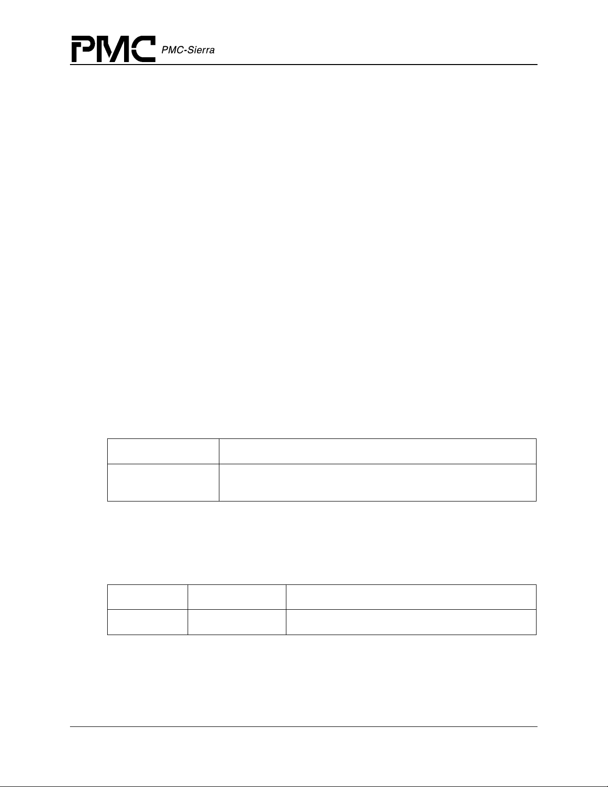
2.1 Driver External Interfaces
Figure 1 illustrates the external interfaces defined for the S/UNI-4x622 device driver.
Figure 1: Driver External Interfaces
Application
PM5358 S/UNI-4x622 Driver Manual
Software Architecture
Function Calls Application Callbacks
Service Callbacks
S/UNI-4x622 Device Driver
Service Calls
Hardware
Interrupts
S/UNI-4x622 Devices
Register
Accesses
RTOS
Application Programming Interface
The driver Application Programming Interface (API) is a list of high-level functions that can be
invoked by application programmers to configure, control and monitor S/UNI-4x622 devices.
The API functions perform operations that are more meaningful from a system’s perspective. The
API includes functions such as:
Proprietary and Confidential to PMC-Sierra, Inc. 14
Document ID: PMC-2010419, Issue 1
Page 15

PM5358 S/UNI-4x622 Driver Manual
Software Architecture
• Initialize the device(s)
• Perform diagnostic tests
• Validate configuration information
• Retrieve status and counts information
The driver API functions use the services of the other driver components to provide this systemlevel functionality to the application programmer.
The driver API also consists of callback routines that are used to notify the application of
significant events that take place within the device(s) and module.
Real-Time OS Interface
The driver’s RTOS interface provides functions that let the driver use RTOS services. The driver
requires the memory, interrupt, and preemption services from the RTOS. The RTOS interface
functions perform the following tasks for the driver:
• Allocate and de-allocate memory
• Manage buffers for the ISR and the DPR
• Enable and disable preemption
The RTOS interface also includes service callbacks. These are functions installed by the driver
using RTOS service calls such as installing interrupts. These service callbacks are invoked when
an interrupt occurs.
Note: You must modify RTOS interface code to suit your RTOS.
Hardware Interface
The hardware interface provides functions that read from and write to the device registers. The
hardware interface also provides a template for an ISR that the driver calls when the device raises
a hardware interrupt. You must modify this function based on the interrupt configuration of your
system.
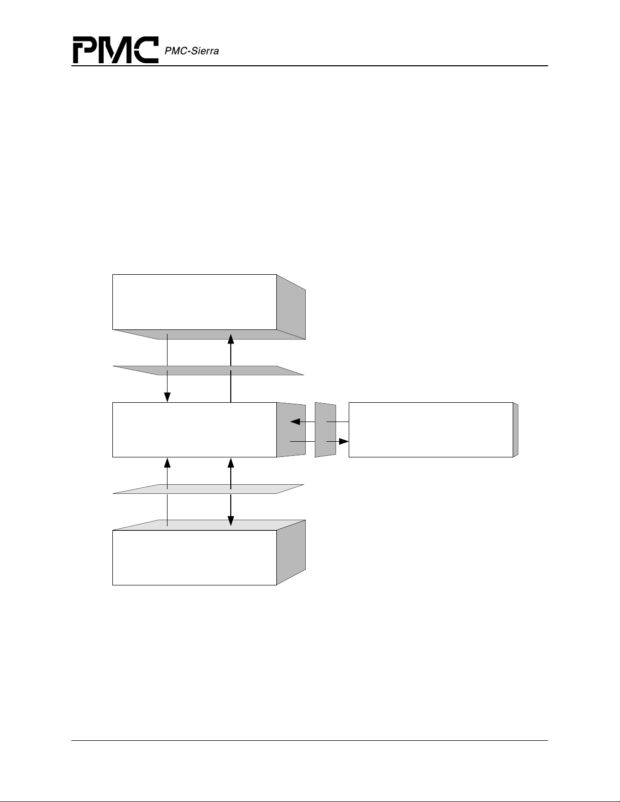
2.2 Main Components
Figure 2 illustrates the top level architectural components of the S/UNI-4x622 device driver. This
applies in both polled and interrupt driven operation. In polled operation the ISR is called
periodically. In interrupt operation the interrupt directly triggers the ISR.
The driver includes eight main components:
• Module and device(s) data-blocks
• Interrupt-service routine
• Deferred-processing routine
Proprietary and Confidential to PMC-Sierra, Inc. 15
Document ID: PMC-2010419, Issue 1
Page 16
• Alarm, status and counts
• Section Overhead
• Line Overhead
• Path Overhead
• Payload Processor
• Interface Configuration
• APS Configuration
Figure 2: Driver Architecture
PM5358 S/UNI-4x622 Driver Manual
Software Architecture
Application
Function
Calls
Application
Callbacks
Deferred
Processing
Routine
Interrupt
Context
Interrupt
Service
Routine
Hardware
Interrupts
Driver API
Alarm, Status &
Statistics
Diagnostics
Module
Data Block
Device Data Blocks
.......
Hardware Interface
S/UNI-4x622 Devices
APS Configuration
Section Overhead
Line Overhead
Path Overhead
Payload Processor
Interface Configuration
Register
Accesses
Service
Callbacks
RTOS
RTOS Interface
Service
Calls
Module Data-Block and Device(s) Data-Blocks
The Module Data-Block (MDB) is the top layer data structure, created by the S/UNI-4x622 driver
to store context information about the driver module, such as:
• Module state
Proprietary and Confidential to PMC-Sierra, Inc. 16
Document ID: PMC-2010419, Issue 1
Page 17

PM5358 S/UNI-4x622 Driver Manual
Software Architecture
• Maximum number of devices
• The DDB(s)
The Device Data-Block (DDB) is contained in the MDB, and initialized by the driver module for
each S/UNI-4x622 device that is registered. There is one DDB per device and there is a limit on
the number of DDBs, and that limit is set by the USER when the module is initialized. The DDB
is used to store context information about one device, such as:
• Device state
• Control information
• Initialization parameters
• Callback function pointers
Interrupt-Service Routine
The S/UNI-4x622 driver provides an ISR called suni4x622ISR that checks if there is any valid
interrupt condition present for the device. This function can be used by a system-specific
interrupt-handler function to service interrupts raised by the device.
The low-level interrupt-handler function that traps the hardware interrupt and calls
suni4x622ISR is system and RTOS dependent. Therefore, it is outside the scope of the driver.
Example implementations of an interrupt handler and functions that install and remove it are
provided as a reference in section 5.2. You can customize these example implementations to suit
your specific needs.
See section 2.5 for a detailed explanation of the ISR and interrupt-servicing model.
Deferred-Processing Routine
The S/UNI-4x622 driver provides a DPR called suni4x622DPR that processes any interrupt
condition gathered by the ISR for that device. Typically, a system specific function, which runs as
a separate task within the RTOS, will call
suni4x622DPR.
Example implementations of a DPR task and functions that install and remove it are provided as a
reference in section 5.2. You can customize these example implementations to suit your specific
needs.
See section 2.5 for a detailed explanation of the DPR and interrupt-servicing model.
Alarms, Status and Counts
The alarm, status and counts section is responsible for monitoring alarms, tracking devices status
information and retrieving counts for each device registered with (added to) the driver.
Proprietary and Confidential to PMC-Sierra, Inc. 17
Document ID: PMC-2010419, Issue 1
Page 18

PM5358 S/UNI-4x622 Driver Manual
Software Architecture
Section Overhead
The Section Overhead section provides functions to control and monitor the section overhead
processing. Read / Write access is given to the section trace message (J0). This message is
compared with a configurable reference and mismatches are reported. Section BIP-8 (B1) errors
are accumulated in a counter that can be read. Section overhead alarms are detected and reported.
For diagnostic purposes, errors can be introduced in the section overhead bytes.
Line Overhead
The Line Overhead section provides functions to configure and monitor the line overhead on both
the receive and transmit sides. Read / Write access is given to the APS bytes (K1 and K2) and
most other overhead bytes. Line BIP-8 (B2) errors are accumulated in a counter that can be read.
Line overhead alarms are detected and reported. For diagnostic purposes, errors can be introduced
in the line overhead bytes. Additional functions are provided to automatically insert line RDI and
line AIS.
Path Overhead
The Path Overhead section provides functions to configure and monitor the path overhead on
both the receive and transmit sides. Read / Write access is given to the path trace message (J1)
and the path signal label (C2). Both are compared with a configurable reference and mismatches
are reported. Path BIP-8 (B3) errors and REI are accumulated in a counter that can be read. Path
overhead alarms are detected and reported. For diagnostic purposes, errors can be introduced in
the path overhead bytes. Additional functions are provided to automatically insert path AIS, and
force generation of individual outgoing justification events.
Payload Processor
The Payload Processor section provides functions to configuring the payload for ATM or POS
processing. Function is provided to configure ATM/POS processing.
Interface Configuration
The Interface Configuration section provides functions to configure the FIFO, line and system
side interface for ATM or POS mode. Functions are provided for FIFO management to separate
the line side timing from the higher layer ATM/POS link layer timing. The Line interface is
responsible for receive/transmit line clock configuration. The System interface is responsible for
configuring the system to UTOPIA Level 3 or POS-PHY Level 3 interface for either ATM or POS
application.
APS Configuration
The APS Configuration section provides function to configure the operating mode for the device
to either a protect or working mate in a APS failover condition.
Proprietary and Confidential to PMC-Sierra, Inc. 18
Document ID: PMC-2010419, Issue 1
Page 19
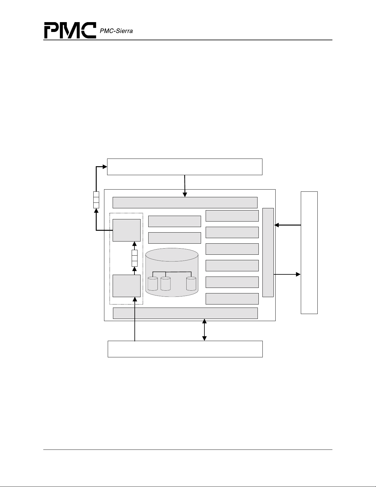
2.3 Software States
Figure 3 shows the software state diagram for the S/UNI-4x622 driver. State transitions occur on
the successful execution of the corresponding transition functions shown. State information helps
maintain the integrity of the MDB and DDB(s) by controlling the set of operations allowed in
each state.
Figure 3: Driver Software States
suni4x622ModuleOpen
PM5358 S/UNI-4x622 Driver Manual
Software Architecture
Idle
suni4x622ModuleStart
MODULE STATES
suni4x622ModuleClose
suni4x622ModuleStop
Ready
suni4x622Reset
Start
suni4x622ModuleClose
Start
suni4x622Add suni4x622Delete
Present
suni4x622Init
suni4x622Activate
Inactive
suni4x622Reset
Active
suni4x622DeActivate
PER-DEVICE STATES
Proprietary and Confidential to PMC-Sierra, Inc. 19
Document ID: PMC-2010419, Issue 1
Page 20

PM5358 S/UNI-4x622 Driver Manual
Software Architecture
Module States
The following is a description of the S/UNI-4x622 module states. See section 4.1 for a detailed
description of the API functions that are used to change the module state.
Start
The driver module has not been initialized. In this state the driver does not hold any RTOS
resources (memory, timers, etc); has no running tasks, and performs no actions.
Idle
The driver module has been initialized successfully. The Module Initialization Vector (MIV) has
been validated, the Module Data Block (MDB) has been allocated and loaded with current data,
the per-device data structures have been allocated, and the RTOS has responded without error to
all the requests sent to it by the driver.
Ready
This is the normal operating state for the driver module. This means that all RTOS resources have
been allocated and the driver is ready for devices to be added. The driver module remains in this
state while devices are in operation.
Device States
The following is a description of the S/UNI-4x622 per-device states. The state that is mentioned
here is the software state as maintained by the driver, and not as maintained inside the device
itself. See section 4.3 for a detailed description of the API functions that are used to change the
per-device state.
Start
The device has not been initialized. In this state the device is unknown by the driver and performs
no actions. There is a separate flow for each device that can be added, and they all start here.
Present
The device has been successfully added. A Device Data Block (DDB) has been associated to the
device and updated with the user context, and a device handle has been given to the USER. In this
state the device performs no actions.
Inactive
In this state the device is configured but all data functions are de-activated including interrupts
and alarms, as well as status and counts functions.
Active
This is the normal operating state for the device. In this state, interrupt servicing or polling is
enabled.
Proprietary and Confidential to PMC-Sierra, Inc. 20
Document ID: PMC-2010419, Issue 1
Page 21
2.4 Processing Flows
This section describes the main processing flows of the S/UNI-4x622 driver components.
The flow diagrams presented here illustrate the sequence of operations that take place for
different driver functions. The diagrams also serve as a guide to the application programmer by
illustrating the sequence in which the application must invoke the driver API.
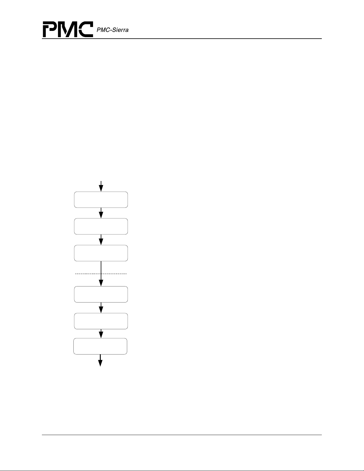
Module Management
The following diagram illustrates the typical function call sequences that occur when initializing
or shutting down the S/UNI-4x622 driver module.
Figure 4: Module Management Flow Diagram
START
suni4x622ModuleOpen
PM5358 S/UNI-4x622 Driver Manual
Software Architecture
Performs module level initializat ion of the driver. Validates the Module
Initialization Vector (MIV). Allocates memory for the MDB and all its
components (i.e. all the memory needed by the driver) and then initializes
the contents of the MDB with the validated MIV.
suni4x622ModuleStart
suni4x622AddInitProfile
suni4x622DeleteInitProfile
suni4x622ModuleStop
suni4x622ModuleClose
END
Performs module level startup of the dri ver. This involves allocating RTOS
resources such as semaphores and timers and installing the ISR handler
and DPR task.
Register an initialization profile. This allows the user to store pre-defined
parameter vectors that are validated ahead of time. When the deviceinitialization function is in voked only a profile number need t o be passed.
This method simplifies and expedites the above operations.
Perform all device level functions here (add, init, acti vate, de-activate,
reset, delete,...)
De-register an initialization profile previously registered with the driver.
Performs Module level shutdown of the driver. This involves deleting all
devices currently installed and de-allocating all timers and s emaphores as
well as removing the IS R handler and DPR task.
Performs module level shutdown of the driver. De-allocates all the driver's
memory.
Device Management
The following figure shows the typica l func tion ca ll sequ ence s that the dr iv er uses to add,
initialize, re-initialize, and delete the S/UNI-4x622 device.
Proprietary and Confidential to PMC-Sierra, Inc. 21
Document ID: PMC-2010419, Issue 1
Page 22
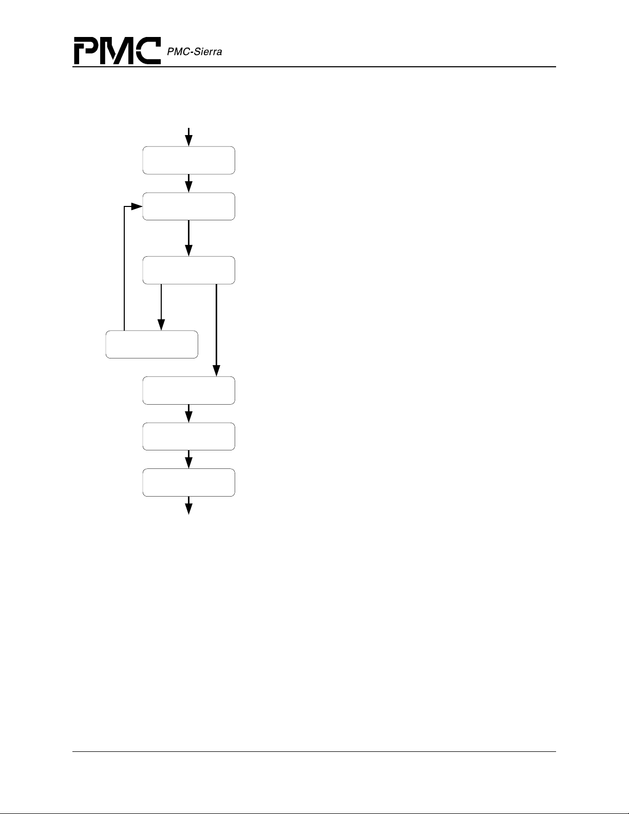
Figure 5: Device Management Flow Diagram
START
PM5358 S/UNI-4x622 Driver Manual
Software Architecture
suni4x622Add
suni4x622Init
suni4x622Activate
suni4x622Reset
suni4x622DeActivate
suni4x622Reset
Detects the new device in hardware, assigns a DDB to the new device
andstores the user's context for the device. Returns a device handle to
the user
Applies a reset to the device and initializes the device registers
and associated RA Ms based on the DIV passed by the user. The
user may only pass a profile number, which corresponds to a
previously saved & validated set of configurations (by using
suni4x622AddInitProfile
Prepares the device f or normal operation by enabling interrupts and
other global enables. ISR routines are installed when the module is
started using
operational and all other API can be invoked.
In order to re-initi alize the device, reset the device using
suni4x622Reset
again.
De-activates the device and removes it from normal operation.
This involves disabling the device interrupts. ISR routines for this
device are removed
when the module is closed.
Applies a software reset to the device to put it in its def ault startup
state.
sysSuni4x622ISRHandlerInstall
and go through the initialization sequence
usingsysSuni4x622ISRHandlerRemove
)
. The device is now
suni4x622Delete
END
Removes the device from the list of devices being controlled by the
S/UNI-4x622 driver. This function de-allocates the device context
information for the device being deleted.
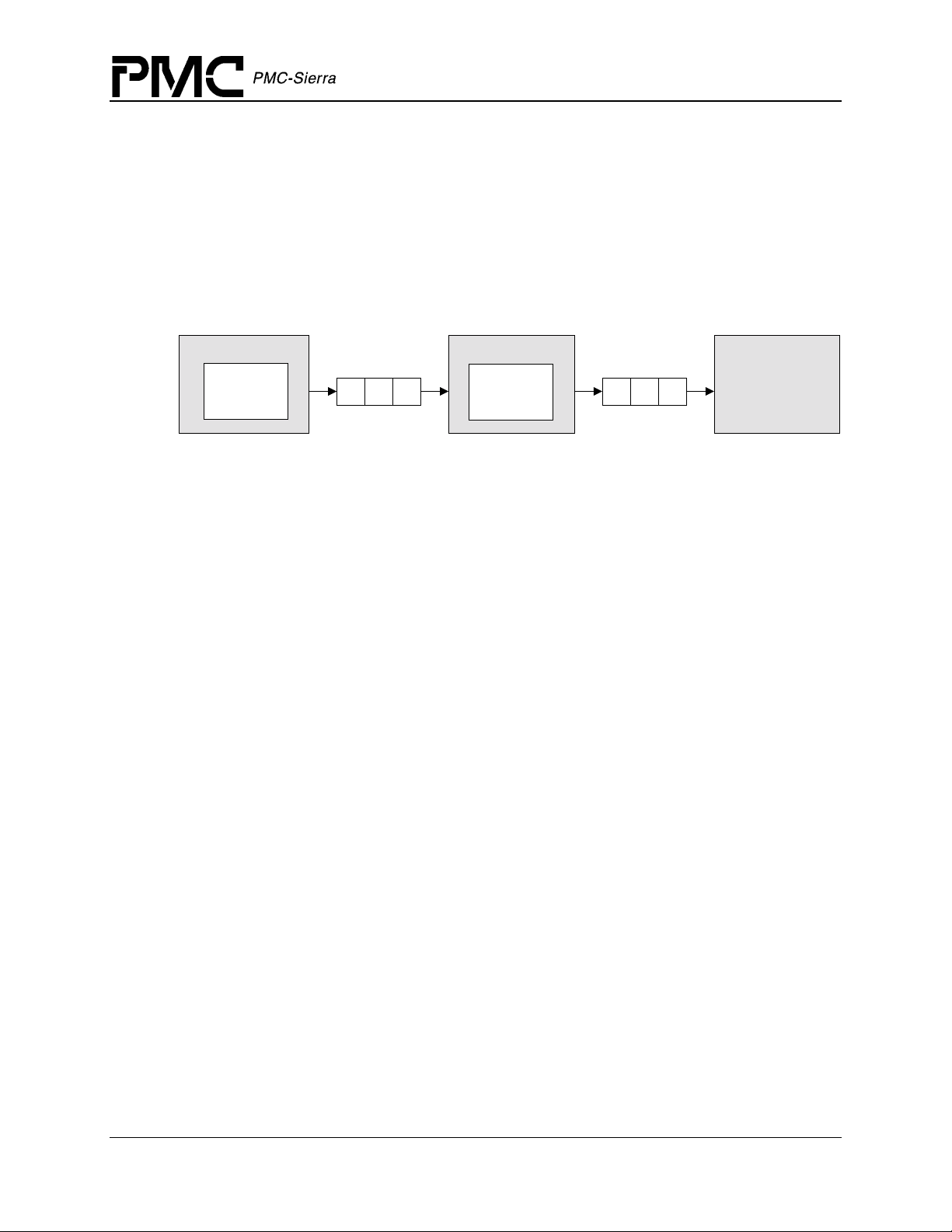
2.5 Interrupt Servicing
The S/UNI-4x622 driver services device interrupts using an Interrupt-Service Routine (ISR) that
traps interrupts, and a Deferred-Processing Routine (DPR) that actually processes the interrupt
conditions and clears them. This lets the ISR execute quickly and exit. Most of the
time-consuming processing of the interrupt conditions is deferred to the DPR by queuing the
necessary interrupt- c ont ext information to the DPR task. The DPR function runs in the context of
a separate task within the RTOS.
Note: Since the DPR task processes potentially serious interrupt conditions, you should set the
DPR task’s priority higher than the application task interacting with the S/UNI-4x622 driver.
Proprietary and Confidential to PMC-Sierra, Inc. 22
Document ID: PMC-2010419, Issue 1
Page 23
PM5358 S/UNI-4x622 Driver Manual
Software Architecture
The driver provides system-independent functions, suni4x622ISR and suni4x622DPR. You
must fill in the corresponding system-specific functions,
sysSuni4x622DPRTask. The system-specific funct ions iso la te the sy stem-specific
sysSuni4x622ISRHandler and
communication mechanism (between the ISR and DPR) from the system-independent functions,
suni4x622ISR and suni4x622DPR.
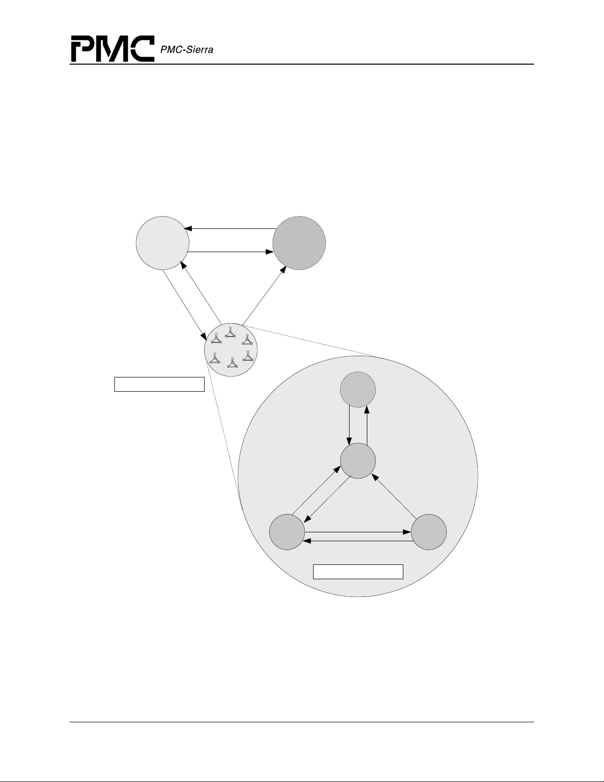
Figure 6 illustrates the interrupt service model used in the S/UNI-4x622 driver design.
Figure 6: Interrupt Service Mode
sysSuni4x622ISRHandler
suni4x622ISR
Interrupt
Context
Information
sysSuni4x622DPRTask
suni4x622DPR
Indication
Callbacks
Application
Note: Instead of using an interrupt service model, you can use a polling service model in the
S/UNI-4x622 driver to process the device’s event-indication registers (see page 26).
Calling suni4x622ISR
An interrupt handler function, which is system dependent, must call suni4x622ISR. But first,
the low-level interrupt-handler function must trap the device interrupts. You must implement this
function to fit your own system. As a reference, an example implementation of the interrupt
handler (sysSuni4x622ISRHandler) appears on page 110. You can customize this example
implementation to suit your needs.
The interrupt handler that you implement (
interrupt vector table of the system processor. It is called when one or more S/UNI-4x622 devices
interrupt the processor. The interrupt handler then calls
active state that has interrupt processing enabled.
sysSuni4x622ISRHandler) is installed in the
suni4x622ISR for each device in the
The
suni4x622ISR function reads from the master interrupt-status registers and the
miscellaneous interrupt-status registers of the S/UNI-4x622. If at least one valid interrupt
condition is found then
information as well as the current device handle. The
disables all the device’s interrupts detected. The
suni4x622ISR fills an Interrupt-Service Vector (ISV) with this status
suni4x622ISR function also clears and
sysSuni4x622ISRHandler function is then
responsible to send this ISV buffer to the DPR task.
Note: Normally you should save the status information for deferred processing by implementing a
message queue. The interrupt hand le r sends the sta tus information to the queue by the
sysSuni4x622ISRHandler.
Proprietary and Confidential to PMC-Sierra, Inc. 23
Document ID: PMC-2010419, Issue 1
Page 24

PM5358 S/UNI-4x622 Driver Manual
Software Architecture
Calling suni4x622DPR
The sysSuni4x622DPRTask function is a system specific function that runs as a separate task
within the RTOS. You should set the DPR task’s priority higher than the application task(s)
interacting with the S/UNI-4x622 driver. In the message-queue implementation model, this task
has an associated message queue. The task waits for messages from the ISR on this message
queue. When a message arrives,
the received ISV.
suni4x622DPR processes the status information and takes appropriate action based on the
Then
specific interrupt condition detected. The nature of this processing can differ from system to
system. Therefore,
suni4x622DPR calls different indication callbacks for different interrupt
conditions.
Typically, you should implement these callback functions as simple message posting functions
that post messages to an application task. However, you can implement the indication callback to
perform processing within the DPR task context and return without sending any messages. In this
case, ensure that this callback function does not call any API functions that would change the
driver’s state, such as
suni4x622Delete. Also, ensure that the callback function is
non-blocking because the DPR task executes while S/UNI-4x622 interrupts are disabled. You can
customize these callbacks to suit your system. See page 103 for example implementations of the
callback functions.
sysSuni4x622DPRTask calls the DPR (suni4x622DPR) with
Note: Since the
suni4x622ISR and suni4x622DPR routines themselves do not specify a
communication mechanism, you have full flexibility in choosing a communication mechanism
between the two. A convenient way to implement this communication mechanism is to use a
message queue, which is a service that most RTOSs provide.
You must implement the two system specific functions,
sysSuni4x622DPRTask. When the driver calls sysSuni4x622ISRHandlerInstall, the
application installs
and the
sysSuni4x622ISRHandlerInstall function also creates the communication chann el betwe en
sysSuni4x622ISRHandler and sysSuni4x622DPRTask. This communication channe l is
sysSuni4x622DPRTask function is spawned as a task by the application. The
sysSuni4x622ISRHandler in the interrupt vector table of the processor,
most commonly a message queue associated with the
Similarly, during removal of interrupts, the driver removes
sysSuni4x622ISRHandler and
sysSuni4x622DPRTask.
sysSuni4x622ISRHandler from
the microprocessor’s interrupt vector table and deletes the task associated with
sysSuni4x622DPRTask.
As a reference, this manual provides example implementations of the interrupt installation and
removal functions on pages 109 and 111. You can customize these prototypes to suit your specific
needs.
Calling suni4x622Poll
Instead of using an interrupt service model, you can use a polling service model in the S/UNI4x622 driver to process the device’s event-indication registers.
Figure 7 illustrates the polling service model used in the S/UNI-4x622 driver design.
Proprietary and Confidential to PMC-Sierra, Inc. 24
Document ID: PMC-2010419, Issue 1
Page 25
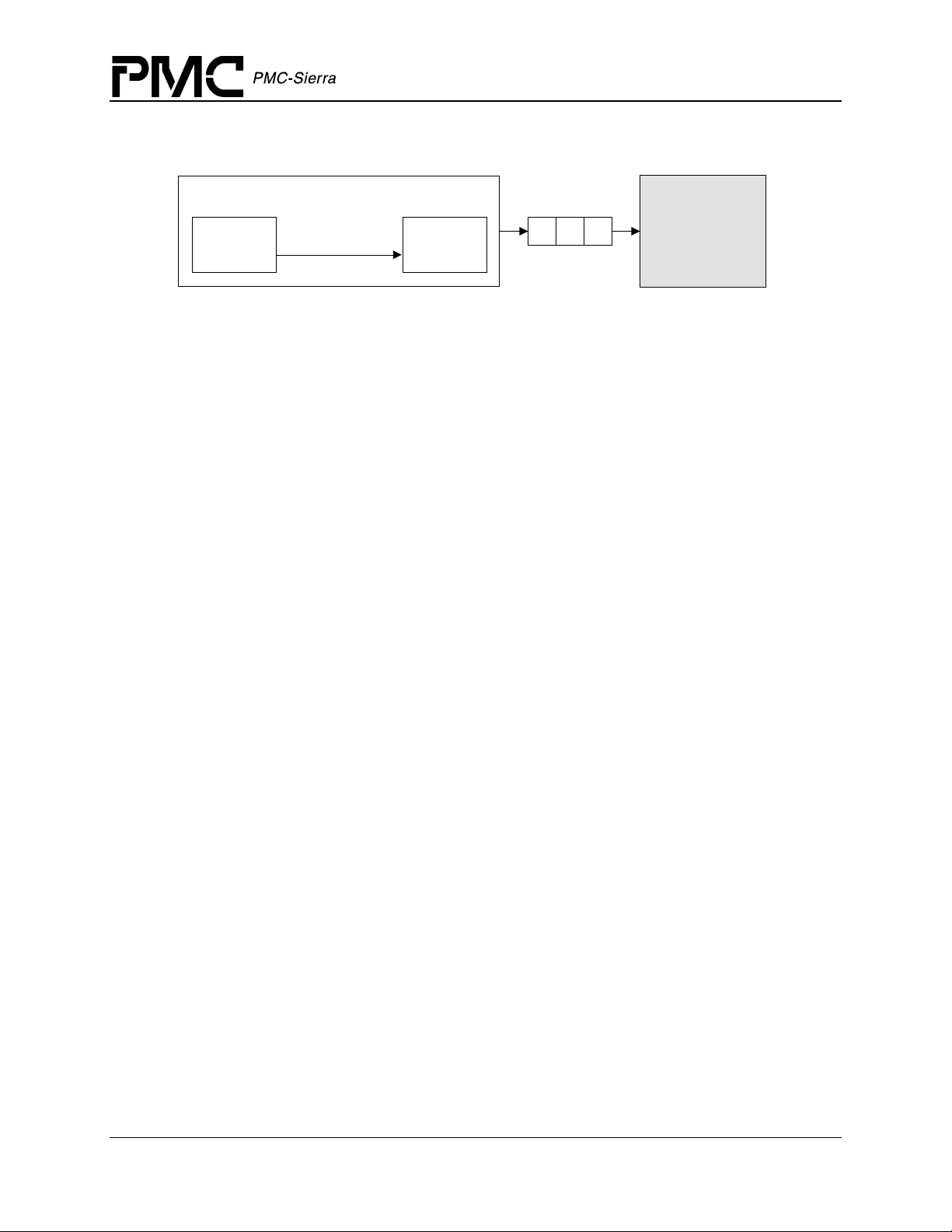
Figure 7: Polling Service Model
PM5358 S/UNI-4x622 Driver Manual
Software Architecture
suni4x622Poll
Interrupt Context
Information
suni4x622DPRsuni4x622ISR
In polling mode, the application is responsible for calling
service any pending error or alarm conditions. When
Indication
Callbacks
Application
suni4x622Poll often enough to
suni4x622Poll is called, the
suni4x622ISR function is called internally.
The
suni4x622ISR function reads from the master interrupt-status registers and the
miscellaneous interrupt-status registers of the S/UNI-4x622. If at least one valid interrupt
condition is found then
suni4x622ISR fills an Interrupt-Service Vector (ISV) with this status
information as well as the current device handle. In polling mode, this ISV buffer is passed to the
DPR task by calling
suni4x622DPR internally.
Proprietary and Confidential to PMC-Sierra, Inc. 25
Document ID: PMC-2010419, Issue 1
Page 26

3 DATA STRUCTURES
This section describes the elements of the driver that configure or control its behavior, and should
therefore be of interest to the application programmer. Included here are the constants, variables
and structures that the S/UNI-4x622 device driver uses to store initialization, configuration and
counts information. The channel number starts from 0. The structure contains arrays of four
elements, where index 0 corresponds to the first channel and index 3 corresponds to the fourth
channel. For more information on our naming convention, the reader is referred to Appendix A
(page 121).
3.1 Constants
The following Constants are used throughout the driver code:
<S/UNI-4x622 ERROR CODES>: error codes used throughout the driver code, returned by
•
the API functions and used in the global error number field of the MDB and DDB. For a
complete list of error codes, see Appendix B (page 125).
PM5358 S/UNI-4x622 Driver Manual
Data Structures
•
SUNI4x622_MAX_DEVS: defines the maximum number of devices that can be supported by
this driver. This constant must not be changed without a thorough analysis of the
consequences to the driver code
•
SUNI4x622_MOD_START, SUNI4x622_MOD_IDLE, SUNI4x622_MOD_READY: the three
possible module states (stored in
SUNI4x622_START, SUNI4x622_PRESENT, SUNI4x622_ACTIVE,
•
SUNI4x622_INACTIVE: the four possible device states (stored in stateDevice)
stateModule)
3.2 Structures Passed by the Application
These structures are defined for use by the application and are passed as argument to functions
within the driver. These structures are the Module Initialization Vector (MIV), the Device
Initialization Vector (DIV) and the ISR mask.
Module Initialization Vector: MIV
Passed via the suni4x622ModuleOpen call, this structure contains all the in formation needed
by the driver to initialize and connect to the RTOS.
•
maxDevs is used to inform the driver how many devices will be operating concurrently
during this session. The number is used to calculate the amount of memory that will be
allocated to the driver. The maximum value that can be passed is
(see section 3.1).
SUNI4x622_MAX_DEVS
Proprietary and Confidential to PMC-Sierra, Inc. 26
Document ID: PMC-2010419, Issue 1
Page 27
PM5358 S/UNI-4x622 Driver Manual
Table 1: S/UNI-4x622 Module Initialization Vector: sSUNI4x622_MIV
Field Name Field Type Field Description
Data Structures
perrModule INT4 *
maxDevs UINT2
maxInitProfs UINT2
(pointer to) errModule (see descript ion in the MDB)
Maximum number of devices supported during this session
Maximum number of initialization profiles
Device Initialization Vector: DIV
Passed via the suni4x622Init call, this structure contains all the information needed by the
driver to initialize a S/UNI-4x622 device. This structure is also passed via the
suni4x622SetInitProfile call when used as an initialization profile.
•
valid indicates that this initialization profile has been properly initialized and may be used
by the USER. This field should be ignored when the DIV is passed directly.
•
pollISR is a flag that indicates the type of interrupt servicing the driver is to use. The
choices are ‘polling’ (
(
SUNI4x622_ISR_MODE). When configured in polling the interrupt capability of the device
is NOT used, and the USER is responsible for calling
actual processing of the event information is the same for both modes.
•
cbackSOH, cbackLOH, cbackRPOH, cbackPYLD, cbackFIFO, cbackIntfSys,
cbackIntfLine
will be used by the DPR to inform the application code of pending events. If these fields are
set as NULL, then any events that might cause the DPR to ‘call back’ the application will be
processed during ISR processing but ignored by the DPR.
SUNI4x622_POLL_MODE), and ‘interrupt driven’
suni4x622Poll periodically. The
and cbackAPS are used to pass the address of application functions that
Table 2: S/UNI-4x622 Device Initialization Vector: sSUNI4x622_DIV
Field Name Field Type Field Description
valid UINT2
pollISR eSUNI4x622_ISR_MODE
cbackSOH sSUNI4x622_CBACK
Indicates that this structure is valid
Indicates the type of ISR / polling to do
Address for the callback function for SOH
events
cbackLOH sSUNI4x622_CBACK
Address for the callback function for LOH
events
cbackRPOH sSUNI4x622_CBACK
Address for the callback function for
RPOH events
Proprietary and Confidential to PMC-Sierra, Inc. 27
Document ID: PMC-2010419, Issue 1
Page 28
PM5358 S/UNI-4x622 Driver Manual
Field Name Field Type Field Description
Data Structures
cbackPYLD sSUNI4x622_CBACK
cbackFIFO sSUNI4x622_CBACK
cbackIntfLine sSUNI4x622_CBACK
cbackIntfSys sSUNI4x622_CBACK
cbackAPS sSUNI4x622_CBACK
cfgGlobal sSUNI4x622_CFG_GLOBAL
cfgChan[4] sSUNI4x622_CFG_CHAN
ISR Enable/Disable Mask
Address for the callback function for
PYLD events
Address for the callback function for FIFO
events
Address for the callback function for Line
Interface events
Address for the callback function for
System Interface events
Address for the callback function for APS
events
Global configuration block
Channel configuration block (4 channels
per device)
Passed via the suni4x622SetMask, suni4x622GetMask and suni4x622ClrMask calls, this
structure contains all the information needed by the driver to enable and disable any of the
interrupts in the S/UNI-4x622.
Table 3: S/UNI-4x622 ISR Mask: sSUNI4x622_MASK_ISR
Field Name Field Type Field Description
maskIntfSys sSUNI4x622_MASK_ISR
_INTF_SYS
maskChan[4] sSUNI4x622_MASK_ISR
_CHAN
maskAPS[4] sSUNI4x622_MASK_ISR
_APS
Interrupt mask for System Interface
Interrupt mask for each channel (4 channels
per device)
Interrupt mask for each channel in the APS
link (4 APS channels per device)
Proprietary and Confidential to PMC-Sierra, Inc. 28
Document ID: PMC-2010419, Issue 1
Page 29
PM5358 S/UNI-4x622 Driver Manual
Table 4: S/UNI-4x622 ISR Mask: sSUNI4x622_MASK_ISR_CHAN
Field Name Field Type Field Description
Data Structures
maskSOH sSUNI4x622_MASK_ISR_
SOH
maskLOH sSUNI4x622_MASK_ISR_
LOH
maskRPOH sSUNI4x622_MASK_ISR_
RPOH
maskPYLD sSUNI4x622_MASK_ISR_
PYLD
maskFIFO sSUNI4x622_MASK_ISR_
FIFO
maskIntfLine sSUNI4x622_MASK_ISR_
INTF_LINE
Interrupt mask for Section Overhead section
Interrupt mask for Line Overhead section
Interrupt mask for Receive Path Overhead
section
Interrupt mask for Payload Processor section
Interrupt mask for FIFO Configuration
section
Interrupt mask for Line Interface section
Table 3: S/UNI-4x622 Section Overhead (SOH) ISR Mask: sSUNI4x622_MASK_ISR_SOH
Field Name Field Type Field Description
oof UINT2
lof UINT2
los UINT2
sbipe UINT2
tiu UINT2
tim UINT2
Out of frame
Loss of frame
Loss of signal
Section BIP error
Section trace unstable
Section trace mismatch
Table 4: S/UNI-4x622 Line Overhead (LOH) ISR Mask: sSUNI4x622_MASK_ISR_LOH
Field Name Field Type Field Description
lais UINT2
lrdi UINT2
Line alarm signal
Line remote defect
Proprietary and Confidential to PMC-Sierra, Inc. 29
Document ID: PMC-2010419, Issue 1
Page 30
PM5358 S/UNI-4x622 Driver Manual
Field Name Field Type Field Description
Data Structures
psbf UINT2
coaps UINT2
coz1s1 UINT2
lbipe UINT2
lreie UINT2
sdber UINT2
sfber UINT2
APS byte failure
Change of APS bytes
Change of synchronization status message
Line BIP error
Line REI error
Signal Defect
Signal Failure
Table 5: S/UNI-4x622 Receive Path Overhead (RPOH) ISR Mask:
sSUNI4x622_MASK__ISR_RPOH
Field Name Field Type Field Description
tiu UINT2
Path trace unstable
tim UINT2
prpslmi UINT2
prpslui UINT2
prdi UINT2
perdi UINT2
pbipe UINT2
pfebe UINT2
pais UINT2
ppse UINT2
pnse UINT2
ploptr UINT2
ardi UINT2
Path trace mismatch
Path signal label mismatch
Path signal label unstable
Path remote defect indication
Path enhanced remote defect indication
Path BIP-8 error
Path REI error
Path AIS state changes
Positive Pointer Justification
Negative Pointer Justification
Path Loss of pointer state changes
AuxRDI state changes
uneq UINT2
Proprietary and Confidential to PMC-Sierra, Inc. 30
Document ID: PMC-2010419, Issue 1
Trace identifier equipped state changes
Page 31

PM5358 S/UNI-4x622 Driver Manual
Field Name Field Type Field Description
Data Structures
psl UINT2
aisc UINT2
lopc UINT2
newptr UINT2
illjreq UINT2
discopa UINT2
invndf UINT2
illptr UINT2
ndf UINT2
Path signal label changed
Pointer AIS event
Lost of pointer concatenation change
New pointer received
Illegal Pointer Justification
Discontinuous change of pointer
Invalid NDF
Illegal pointer
NDF event
Table 6: S/UNI-4x622 ISR Mask: sSUNI4x622_MASK_ISR_PYLD
Field Name Field Type Field Description
lcd UINT2
Change in loss of cell delineation
hcs UINT2
fcs UINT2
rxcpxfer UINT2
txcpxfer UINT2
abrt UINT2
maxl UINT2
minl UINT2
oocd UINT2
Detection of corrected or uncorrected HCS error
Detection of FCS error
Transfer of received CP accumulated interval complete
Transfer of transmit CP accumulated counter data completed
Reception of aborted packet
Reception of packet exceeding maximum packet length
Reception of packet below minimum packet length
Change in cell delineation state
Table 7: S/UNI-4x622 ISR Mask: sSUNI4x622_MASK_ISR_FIFO
Field Name Field Type Field Description
rxcpfovr UINT2
Rx CP FIFO overrun
Proprietary and Confidential to PMC-Sierra, Inc. 31
Document ID: PMC-2010419, Issue 1
Page 32

PM5358 S/UNI-4x622 Driver Manual
Field Name Field Type Field Description
Data Structures
rxfpfovr UINT2
txfpfudr UINT2
Rx FP FIFO overrun
Tx FP FIFO underrun
Table 10: S/UNI-4x622 ISR Mask: sSUNI4x622_MASK_ISR_INTF_LINE
Field Name Field Type Field Description
wansinten UINT2
lot UINT2
rool UINT2
dool UINT2
WANS phase detector averaging period has begun
Loss of transition
Recovered reference out of lock
Recovered data out of lock
Table11: S/UNI-4x622 ISR Mask: sSUNI4x622_MASK_ISR_INTF_SYS
Field Name Field Type Fi el d Description
txop UINT2
TSOP or TSEP is not asserted with the first or last word of a
POS-PHY packet
unprov UINT2
Detection of non-existent channel buf f er duri ng in- band
addressing
cam UINT2
tprty UINT2
tsoc UINT2
fovr UINT2
funr UINT2
Data field mismatch
Tx Parity error
Start of cell re-alig nment
TUL3 FIFO overrun
RUL3 FIFO underrun
Table12: S/UNI-4x622 ISR Mask: sSUNI4x622_MASK_ISR_APS
Field Name Field Type Field Description
bip UINT2
los UINT2
BIP-8 error
Loss of signal
Proprietary and Confidential to PMC-Sierra, Inc. 32
Document ID: PMC-2010419, Issue 1
Page 33

PM5358 S/UNI-4x622 Driver Manual
Field Name Field Type Field Description
Data Structures
lof UINT2
oof UINT2
lot UINT2
dool UINT2
rool UINT2
ese UINT2
pj UINT2
Los of frame
Out of frame
Loss of transition
Recovered data out of lock
Recovered reference out of lock
Elastic store FIFO error
Pointer Justification
3.3 Structures in the Driver’s Allocated Memory
These structures are defined and used by the driver and are part of the context memory allocated
when the driver is opened. These structures are the Module Data Block (MDB), the Device Data
Block (DDB).
Module Data Block: MDB
The MDB is the top-level structure for the module. It contains configuration data about the
module level code and pointers to configuration data about the device level codes.
errModule most of the module API functions return a specific error code directly. When the
•
returned code is
to carry the specified error code back to the application. Under those circumstances, the
proper error code is recorded in this element. The element is the first in the structure so that
the USER can cast the MDB pointer into a INT4 pointer and retrieve the local error (this
eliminates the need to include the MDB tem plate int o th e applica tion code).
•
valid indicates that this structure has been properly initialized and may be read by the
USER.
stateModule contains the current state of the module and could be set to:
•
SUNI4x622_MOD_START, SUNI4x622_MOD_IDLE or SUNI4x622_MOD_READY.
Table 8: S/UNI-4x622 Module Data Block: sSUNI4x622_MDB
Field Name Field Type Field Description
errModule INT4
SUNI4x622_FAILURE, this indicates that the top-lev el funct ion was not able
Global error Indicator for module calls
valid UINT2
Proprietary and Confidential to PMC-Sierra, Inc. 33
Document ID: PMC-2010419, Issue 1
Indicates that this structure has been
Page 34

PM5358 S/UNI-4x622 Driver Manual
Field Name Field Type Field Description
initialized
Data Structures
stateModule eSUNI4x622_MOD_STATE
Module state; can be one of the following
IDLE or READY
maxDevs UINT2
numDevs UINT2
maxInitProfs UINT2
pddb sSUNI4x622_DDB *
Maximum number of devices supported
Number of devices currently registered
Maximum number of initialization profiles
(array of) Device Data Blocks (DDB) in
context memory
pinitProfs sSUNI4x622_DIV *
(array of) Initialization profiles in context
memory
Device Data Block: DDB
The DDB is the top-level structure for each device. It contains configuration data about the device
level code and pointers to configuration data about device level sub-blocks.
errDevice most of the device API functions return a specific error code directly. When the
•
returned code is
to carry the specific error code back top the application. In addition, some device functions do
not return an error code. Under those circumstances, the proper error code is recorded in this
element. The element is the fi rs t in the structur e so that the USER can cast the DD B point er
to a INT4 pointer and retrieve the local error (this eliminates the need to include the DDB
template in the application code).
SUNI4x622_FAILURE, this indicates that the top-lev el funct ion was not able
•
valid indicates that this structure has been properly initialized and may be read by the
USER.
•
stateDevice contains the current state of the device and could be set to:
SUNI4x622_START, SUNI4x622_PRESENT, SUNI4x622_ACTIVE or
SUNI4x622_INACTIVE.
usrCtxt is a value that can be used by the USER to identify the device during the execution
•
of the callback functions. It is passed to the driver when
suni4x622Add is called and
returned to the USER in the DPV when a callback function is invoked. The element is unused
by the driver itself and may contain any value.
Table 9: S/UNI-4x622 Device Data Block: sSUNI4x622_DDB
Field Name Field Type Field Description
errDevice INT4
valid UINT2
Proprietary and Confidential to PMC-Sierra, Inc. 34
Document ID: PMC-2010419, Issue 1
Global error indicator for device calls
Indicates that this structure has been
Page 35

PM5358 S/UNI-4x622 Driver Manual
Field Name Field Type Field Description
initialized
Data Structures
stateDevice eSUNI4x622_DEV_STATE
baseAddr void *
usrCtxt sSUNI4x622_USR_CTXT
profileNum UINT2
pollISR eSUNI4x622_ISR_MODE
cbackSOH sSUNI4x622_CBACK
cbackLOH sSUNI4x622_CBACK
cbackRPOH sSUNI4x622_CBACK
cbackPYLD sSUNI4x622_CBACK
Device State; can be one of the following
PRESENT, ACTIVE or INACTIVE
Base address of the device
Stores the user’s context for the device. It
is passed as an input parameter when the
driver invokes an application callback
Profile number used at initialization
Indicates the current type of ISR / polling
Address for the callback function for SOH
events
Address for the callback function for LOH
events
Address for the callback function for
RPOH events
Address for the callback function for
PYLD events
cbackFIFO sSUNI4x622_CBACK
cbackIntfLine sSUNI4x622_CBACK
cbackIntfSys sSUNI4x622_CBACK
cbackAPS sSUNI4x622_CBACK
cfgGlobal sSUNI4x622_CFG_GLOBAL
cfgChan[4] sSUNI4x622_CFG_CHAN
mask sSUNI4x622_MASK_ISR
Address for the callback function for FIFO
events
Address for the callback function for Line
Interface events
Address for the callback function for
System Interface events
Address for the callback function for APS
events
Global configuration block
Channel configuration block ( 4 channels
per device)
Interrupt Enable Mask
Proprietary and Confidential to PMC-Sierra, Inc. 35
Document ID: PMC-2010419, Issue 1
Page 36

PM5358 S/UNI-4x622 Driver Manual
Data Structures
Device-wide Global Configuration
Table 10: S/UNI-4x622 Input/Output Configuration: sSUNI4x622_CFG_GLOBAL
Field Name Field Type Field Description
sonetsel UINT1
cfgIntfSys sSUNI4x622_CFG_INTF_SYS_GLOBAL
Select SONET/SDH mode
System Interface configuration
block
cfgIntfLine sSUNI4x622_CFG_INTF_LINE_GLOBAL
Line Interface configuration
block
Per-Channel Configuration
Table 11: S/UNI-4x622 Channel Configuration: sSUNI4x622_CFG_CHAN
Field Name Field Type Field Description
cfgSOH sSUNI4x622_CFG_SOH
Section Overhead Processor (SOH) configuration
block
cfgLOH sSUNI4x622_CFG_LOH
Line Overhead Processor (LOH) configuration
block
cfgRPOH sSUNI4x622_CFG_RPOH
Receive Path Overhead Processor (RPOH)
configuration block
cfgTPOH sSUNI4x622_CFG_TPOH
Transmit Path Overhead Processor (TPOH)
configuration block
cfgPYLD sSUNI4x622_CFG_PYLD
cfgFIFO sSUNI4x622_CFG_FIFO
cfgLine sSUNI4x622_CFG_INTF
_LINE
Proprietary and Confidential to PMC-Sierra, Inc. 36
Document ID: PMC-2010419, Issue 1
Payload Processor (PYLD) configuration block
FIFO configuration
Line Interface configuration block
Page 37

PM5358 S/UNI-4x622 Driver Manual
Data Structures
Per-Channel Section Overhead (SOH) Configuration
Table 12: S/UNI-4x622 Section Overhead Configuration: sSUNI4x622_CFG_SOH
Field Name Field Type Field Description
algo2 UINT1
Selects framing pattern used to determine and maintain the
frame alignment
sblkbip UINT1
dds UINT1
ds UINT1
zeroen UINT1
Controls accumulation of section BIP errors
Rx descrambling
Tx scrambling
Selects whether all zero trace identifier messages accepted
or ignored
Per-Channel Line Overhead (LOH) Configuration
Table 13: S/UNI-4x622 Line Overhead Configuration: sSUNI4x622_CFG_LOH
Field Name Field Type Fi el d Description
laisdet UINT1
lrdidet UINT1
Selects Line AIS detection algorithm
Selects Line RDI detection algorithm
lbipword UINT1
sdlrdi UINT1
sflrdi UINT1
loflrdi UINT1
loslrdi UINT1
rtimlrdi UINT1
Selects accumulation of line BIP errors
Controls whether signal degrade can cause LRDI insertion
Controls whether signal failure can cause LRDI insertion
Controls whether loss of frame can cause LRDI insertion
Controls whether loss of signal can caus e LRDI insertion
Controls whether section trace message mismatch can cause
LRDI insertion
rtiulrdi UINT1
Controls whether section trace message unstable can cause
LRDI insertion
laislrdi UINT1
autolfebe UINT1
Proprietary and Confidential to PMC-Sierra, Inc. 37
Document ID: PMC-2010419, Issue 1
Controls whether line AIS can cause LRDI insertion
Controls whether line BIP errors can cause FEBE insertion
Page 38

Field Name Field Type Fi el d Description
PM5358 S/UNI-4x622 Driver Manual
Data Structures
allones UINT1
Controls whether incoming AIS will force the downstream
Sonet/SDH frame to all ones
sdins UINT1
sfins UINT1
lofins UINT1
losins UINT1
rtimins UINT1
rtiuins UINT1
dccais UINT1
Controls whether SD can cause Line AIS insertion
Controls whether SF can cause Line AIS insertion
Controls whether LOF can cause Line AIS insertion
Controls whether LOS can cause Line AIS insertion
Controls whether section TIM can cause Line AIS insertion
Controls whether section TIU can cause Line AIS insertion
Controls whether LOS or LOF can force all ones in the DCC
outputs
Per-Channel Receive Path Overh ead (R PO H) Configuration
Table 14: S/UNI-4x622 Receive Path Overhead Configuration: sSUNI4x622_CFG_RPOH
Field Name Field Type Fi el d Description
enss UINT1
Selects SS bits are taking into account in the pointer interpreter
state machine
sos UINT1
iinvcnt UINT1
zeroen UINT1
Enables justification more than 3 frames ago
Selects behavior of the consecutive INV_POINT event counter
Selects whether all zero trace identifier messages accepted or
ignored
Per-Channel Transmit Path Overhead (TPOH) Con fig u rat ion
Table 15: S/UNI-4x622 Transmit Path Overhead Configuration: sSUNI4x622_CFG_TPOH
Field Name Field Type Fi el d Description
persist UINT1
Control of the persistence of the RDI asserted into the
transmitted stream
Proprietary and Confidential to PMC-Sierra, Inc. 38
Document ID: PMC-2010419, Issue 1
Page 39

Field Name Field Type Fi el d Description
PM5358 S/UNI-4x622 Driver Manual
Data Structures
lcdprdi UINT1
alrmprdi UINT1
paisprdi UINT1
pslmprdi UINT1
lopprdi UINT1
lopconprdi UINT1
ptiuprdi UINT1
ptimprdi UINT1
paisconprdi UINT1
Controls whether loss of cell delineation can cause PRDI
insertion
Controls whether LOS,LOF or LAIS can cause PRDI
insertion
Controls whether PAIS can cause PRDI insertion
Controls whether Path signal label mismatch can cause
PRDI insertion
Controls whether loss of pointer indications can cause
PRDI insertion
Controls whether loss of pointer concatenation indications
can cause PRDI insertion
Controls whether path trace identifier unstable can cause
PRDI insertion
Controls whether path trace identifier mismatch can cause
PRDI insertion
Controls whether path AIS concatenation events can cause
PRDI insertion
uneqprdi UINT1
lcdeprdi UINT1
noalmeprdi UINT1
nopaiseprdi UINT1
pslmeprdi UINT1
nolopeprdi UINT1
nolopconeprdi UINT1
ptiueprdi UINT1
Controls whether unequipped path signal label can cause
PRDI insertion
Controls whether loss of cell delineation can cause EPRDI
insertion
Controls whether LOS,LOF or LAIS will disable EPRDI
insertion
Controls whether PAIS will disable EPRDI insertion
Controls whether Path signal label mismatch can cause
EPRDI insertion
Controls whether loss of pointer indications can disable
EPRDI insertion
Controls whether loss of pointer concatenation indications
will disable EPRDI insertion
Controls whether path trace identifier unstable can cause
EPRDI insertion
Proprietary and Confidential to PMC-Sierra, Inc. 39
Document ID: PMC-2010419, Issue 1
Page 40

Field Name Field Type Fi el d Description
PM5358 S/UNI-4x622 Driver Manual
Data Structures
ptimeprdi UINT1
paisconpais UINT1
lopconpais UINT1
pslmpais UINT1
pslupais UINT1
loppais UINT1
tiupais UINT1
timpais UINT1
autopfebe UINT1
Controls whether path trace identifier mismatch can cause
EPRDI insertion
Controls whether AIS concatenation events can cause PAIS
insertion
Controls whether loss of pointer concatenation events can
cause PAIS insertion
Controls whether path signal label mismatch can cause
PAIS insertion
Controls whether path signal label unstable can cause PAIS
insertion
Controls whether loss of signal can caus e PAIS insertion
Controls whether path TIU can cause PAIS insertion
Controls whether path TIM can cause PAIS insertion
Controls whether path BIP errors can cause FEBE insertion
Per-Channel Payload Pr oce sso r Configuration
Table 16: S/UNI-4x622 Payload Processor: sSUNI4x622_CFG_PYLD
Field Name Field Type Field Description
rxddscr UINT1
rxcpdiscor UINT1
rxcpidlepass UINT1
rxcpccdis UINT1
rxcplcdc UINT2
rxcpidlehdr UINT1
rxcpidlemask UINT1
rxfpfcssel UINT1
rxfpfcspass UINT1
RX descrambles payload
Disables ATM HCS error correction
RX ignore idle cell header pattern and mask for ATM cells
Disables cell delineation and filtering
RX LCD Count Threshold
RX idle cell header
RX idle cell mask
RX FCS select
RX selects FCS stripping
Proprietary and Confidential to PMC-Sierra, Inc. 40
Document ID: PMC-2010419, Issue 1
Page 41

Field Name Field Type Field Description
PM5358 S/UNI-4x622 Driver Manual
Data Structures
rxfpminpl UINT1
rxfpmaxpl UINT2
txdscr UINT1
txcpidlehdr UINT1
txcpidlepyld UINT1
txfpfcssel UINT1
mode UINT1
txfpipgap UINT1
RX minimum packet length
RX maximum packet length
TX scrambles outgoing payload
TX idle cell head er
TX idle cell payload
TX FCS select
ATM or POS mode
The number of Flag Sequence characters inserted between
each POS Frame
Per-Ch an n el F I FO Configuration
Table 17: S/UNI-4x622 FIFO Configuration: sSUNI4x622_CFG_FIFO
Field Name Field Type Field Description
rxfpril UINT1
txfptil UINT1
RX FIFO overrun before frame receive
TX FIFO fill level before frame transmit
Per-Channel Clock Interface Configuration
Table 18: S/UNI-4x622 Clock Interface Configuration: sSUNI4x622_CFG_CLK
Field Name Field Type Fi el d Description
loopt UINT1
dccsel UINT1
Selects REFCLK or recovered clock as tx source
Configures whether the DCC is configured for section or line
DCC operation
tfpen UINT1
Controls whether frame pulse input used for alignment
Proprietary and Confidential to PMC-Sierra, Inc. 41
Document ID: PMC-2010419, Issue 1
Page 42

PM5358 S/UNI-4x622 Driver Manual
Data Structures
Per-Channel RALRM Configuration
Table 19: S/UNI-4x622 Clock Interface Configuration: sSUNI4x622_CFG_RALRM
Field Name Field Type Fi el d Description
losen UINT1
lofen UINT1
oofen UINT1
laisen UINT1
lrdien UINT1
sdberen UINT1
sfberen UINT1
stimen UINT1
lopen UINT1
lcden UINT1
paisen UINT1
prdien UINT1
Controls whether LOS set RALRM output
Controls whether LOF set RALRM output
Controls whether OOF set RALRM output
Controls whether line AIS set RALRM output
Controls whether Line RDIset RALRM output
Controls whether SD threshold event set RALRM output
Controls whether SF threshold event set RALRM output
Controls whether section TIM set RALRM output
Controls whether LOP set RALRM output
Controls whether LCD set RALRM output
Controls whether path AIS set RALRM output
Controls whether path RDI set RALRM output
perdien UINT1
pslmen UINT1
Controls whether path ERDI set RALRM output
Controls whether path signal label mismatch set RALRM
output
ptimen UINT1
conen UINT1
Controls whether path TIM set RALRM output
Controls whether pointer concatenation violation set RALRM
output
Per-Channel Line Interface Configuration
Table 20: S/UNI-4x622 Line Interface Configuration: sSUNI4x622_CFG_INTF_LINE
Field Name Field Type Field Description
cfgClk sSUNI4x622_CFG_CLK
Proprietary and Confidential to PMC-Sierra, Inc. 42
Document ID: PMC-2010419, Issue 1
Clock configuration block
Page 43

PM5358 S/UNI-4x622 Driver Manual
Field Name Field Type Field Description
Data Structures
cfgRALRM sSUNI4x622_CFG_RALRM
RALRM configuration block
Device-wide System Interface Configuration
Table 21: S/UNI-4x622 Global System Interface Configuration:
sSUNI4x622_CFG_INTF_SYS_GLOBAL
Field Name Field Type Field Description
tul3prtyp UINT1
tul3l3mode UINT1
tul3atmsiglbl UINT1
tul3possiglbl UINT1
rul3prtyp UINT1
rul3l3mode UINT1
rul3atmsiglbl UINT1
TUL3 parity
TUL3 mode
TUL3 ATM signal label
TUL3 POS signal label
RUL3 parity
RUL3 mode
RUL3 ATM signal label
rul3possiglbl UINT1
tul3atmfifodp UINT1
tul3posfifolwm UINT1
tul3posfifohwm UINT1
tul3cellform UINT1
rul3cellform UINT1
rul3pause UINT1
rul3tran UINT1
RUL3 POS signal label
TUL3 ATM FIFO depth
TUL3 POS FIFO low water mark
TUL3 POS FIFO high water mark
TUL3 cell size (52 or 56)
RUL3 cell size (52 or 56)
RUL3 minimum time between POS transfer burst
RUL3 maximum single-channel transfer
Proprietary and Confidential to PMC-Sierra, Inc. 43
Document ID: PMC-2010419, Issue 1
Page 44

Device-Wide Line Interface Configuration
Table 22: S/UNI-4x622 Global Line Interface Configuration:
sSUNI4x622_CFG_INTF_LINE_GLOBAL
Field Name Field Type Fi el d Description
PM5358 S/UNI-4x622 Driver Manual
Data Structures
rsel UINT1
Selects which channel is used as a clock source for the rx clock
output pin
tsel UINT1
Selects which channel is used as a clock source for the tx clock
output pin
Table 23: S/UNI-4x622 Signal Failure Configuration: sSUNI4x622_CFG_SF
Field Name Field Type Fi el d Description
sfcmode UINT1
Clears alarm using a window size 8 times longer than the alarm
declaration window size
sfsmode UINT1
sfberten UINT1
Saturates the BIP count on a per window basis
Automatic monitoring of line bit error rate threshold events by
the SF BERM
sfsap UINT4
sfsth UINT4
SF Accumulation period
SF Saturation Threshold
sfdth UINT4
sfcth UINT4
SF Declaring Threshold
SF Clearing Threshold
Table 24: S/UNI-4x622 Signal Defect Configuration: sSUNI4x622_CFG_SD
Field Name Field Type Fi el d Description
sdcmode UINT1
Clears alarm using a window size 8 times longer than the alarm
declaration window size
sdsmode UINT1
sdberten UINT1
Saturates the BIP count on a per window basis
Automatic monitoring of line bit error rate threshold events by
the SF BERM
Proprietary and Confidential to PMC-Sierra, Inc. 44
Document ID: PMC-2010419, Issue 1
Page 45

Field Name Field Type Fi el d Description
PM5358 S/UNI-4x622 Driver Manual
Data Structures
sdsap UINT4
sdsth UINT4
sddth UINT4
sdcth UINT4
SD Accumulation period
SD Saturation Threshold
SD Declaring Threshold
SD Clearing Threshold
Table 25: S/UNI-4x622 Channel Status Block: sSUNI4x622_STATUS_CHAN
Field Name Field Type Field Description
statusSOH sSUNI4x622_STATUS
_SOH
statusLOH sSUNI4x622_STATUS
_LOH
statusRPOH sSUNI4x622_STATUS
_RPOH
statusPYLD sSUNI4x622_STATUS
_PYLD
Alarms, status and counts from the Section
Overhead (SOH) section
Alarms, status and counts from the Line Overhead
(LOH) section
Alarms, status and counts from the Receive Path
Overhead (RPOH) Section
Alarms, status and counts from the Payload Section
statusLINE sSUNI4x622_STATUS
_INTF_LINE
Alarms, status and counts from Line Interface
section
Section Overhead (SOH) Status
Table 26: S/UNI-4x622 Section Overhead Status: sSUNI4x622_STATUS_SOH
Field Name Field Type Fi el d Description
oof UINT1
lof UINT1
los UINT1
tiu UINT1
tim UINT1
Out of frame defect
Loss of frame defect
Loss of signal defect
Section trace identifier unsta bl e
Section trace identifier mismatch
Proprietary and Confidential to PMC-Sierra, Inc. 45
Document ID: PMC-2010419, Issue 1
Page 46

PM5358 S/UNI-4x622 Driver Manual
Line Overhead (LOH) Status
Table 27: S/UNI-4x622 Line Overhead Status: sSUNI4x622_STATUS_LOH
Field Name Field Type Field Description
Data Structures
k1 UINT1
k2 UINT1
s1 UINT1
laisdet UINT1
lrdidet UINT1
sfber UINT1
sdber UINT1
psbf UINT1
Receive K1
Receive K2
Receive S1
Line alarm signal defect
Line remote defect indication
Signal Failure
Signal Degrade
APS byte failure
Receive Path Overhead (RPOH) Status
Table 28: S/UNI-4x622 Receive Path Overhead Processor Status:
sSUNI4x622_STATUS_RPOH
Field Name Field Type Fi el d Description
perdi UINT1
Path enhanced RDI status(filtered received EPRDI bits,G1 bit
5,6 and 7)
rxptr UINT2
rxss UINT1
txptr UINT2
txss UINT1
apsl UINT1
epsl UINT1
plop UINT1
pais UINT1
Proprietary and Confidential to PMC-Sierra, Inc. 46
Document ID: PMC-2010419, Issue 1
Last payload pointer read from the receive stream
Rx SS (DD) bits
Current payload pointer being inserted in the tx stream
Tx SS bits
Accepted path signal label
Expected path signal label
Path lost of pointer status
Path AIS status
Page 47

Field Name Field Type Fi el d Description
PM5358 S/UNI-4x622 Driver Manual
Data Structures
prdi UINT1
tiu UINT1
tim UINT1
uneq UINT1
pslu UINT1
pslm UINT1
ardi UINT1
aisc UINT1
lopc UINT1
Path RDI status
Path trace identifier unst able
Path trace identifier mism atch
Equip status of the path signal label
Path signal label unstable
Path signal label mismatch
Aux RDI status
AIS concatenated
Loss of pointer concatenated
Payload Processor Status
Table 30: S/UNI-4x622 Payload Status: sSUNI4x622_STATUS_PYLD
Field Name Field Type Field Description
rxcpovr UINT1
txcpovr UINT1
lcd UINT1
oocd UINT1
RXCP accum ulat ion trans fer ov errun
TXCP accumulation transfer overrun
Loss of cell delineation
out of cell delineation
Clock Status
Table 29: S/UNI-4x622 Clock Status: sSUNI4x622_STATUS_CLK
Field Name Field Type Field Description
tclka UINT1
rclka UINT1
rfclka UINT1
TCLKA active
RCLKA active
RFCLK active
Proprietary and Confidential to PMC-Sierra, Inc. 47
Document ID: PMC-2010419, Issue 1
Page 48

PM5358 S/UNI-4x622 Driver Manual
Field Name Field Type Field Description
Data Structures
tfclka UINT1
refclka UINT1
TFCLK active
REFCLKA active
Line Interface Status
Table 30: S/UNI-4x622 Line Interface Status: sSUNI4x622_STATUS_INTF_LINE
Field Name Field Type Field Description
statusClk sSUNI4x622_STATUS_CLK
Clock interface status
Counters (CNT)
Table 31: S/UNI-4x622 Counters: sSUNI4x622_CNTR_CHAN
Field Name Field Type Field Description
cntrSOH sSUNI4x622_CNTR_SOH
cntrLOH sSUNI4x622_CNTR_LOH
Counters for Section Overhead (SOH) section
Counters for Line Overhead (LOH) section
cntrRPOH sSUNI4x622_CNTR_RPOH
Counters for Receive Path Overhead (RPOH)
section
cntrPYLD sSUNI4x622_CNTR_PYLD
Counters for Payload Processor (PYLD) section
Section Overhead (SOH) Counter
Table 32: S/UNI-4x622 Section Overhead (SOH) Counters: sSUNI4x622_CNTR_SOH
Field Name Field Type Field Description
sbe UINT2
Section BIP error counter
Proprietary and Confidential to PMC-Sierra, Inc. 48
Document ID: PMC-2010419, Issue 1
Page 49

PM5358 S/UNI-4x622 Driver Manual
Data Structures
Line Overhead (LOH) Counter
Table 33: S/UNI-4x622 Line Overhead (LOH) Counters: sSUNI4x622_CNTR_LOH
Field Name Field Type Field Description
lbe UINT4
lfe UINT4
Line BIP error counter
Line REI error counter
Receive Path Overhead (RPOH) Counter
Table 34: S/UNI-4x622 Receive Path Overhead (RPOH) Counters:
sSUNI4x622_CNTR_RPOH
Field Name Field Type Field Description
pbe UINT2
pfe UINT2
Path BIP error counter
Path REI error counter
Payload Processor (PYLD) Counter
Table 35: S/UNI-4x622 Payload Processor Counters: sSUNI4x622_CNTR_PYLD
Field Name Field Type Field Description
rxcpchcs UINT1
rxcpuhcs UINT1
rxcprcell UINT4
rxcpicell UINT4
txcptcell UINT4
rxfprbyte UINT4
rxfprframe UINT4
rxfprabrf UINT2
rxfprfcsef UINT2
Proprietary and Confidential to PMC-Sierra, Inc. 49
Document ID: PMC-2010419, Issue 1
Rx corrected HCS error count
Rx uncorrected HCS error count
Rx cell count
Rx idle cell count
Tx cell count
Rx byte count
Rx frame count
Rx aborted frame count
Rx FCS error frame count
Page 50

PM5358 S/UNI-4x622 Driver Manual
Field Name Field Type Field Description
Data Structures
rxfprminlf UINT2
rxfprmaxlf UINT2
txfptbyte UINT4
txfptframe UINT4
txfptusrabf UINT4
txfptferabf UINT4
Rx minimum length error frame count
Rx maximum length error frame count
Tx byte count
Tx frame count
Tx user aborted frame count
Tx underrun/error aborted frame count
3.4 Structures Passed through RTOS Buffers
Interrupt-Service Vector: ISV
This buffer structure is used to capture the status of the device (during a poll or ISR processing)
for use by the Deferred-Processing Routine (DPR). It is the template for all device registers that
are involved in exception processing. It is the application’s responsibility to create a pool of ISV
buffers (using this template to determine the buffer’s size) when the driver calls the USERsupplied
the driver via
sysSuni4x622ISVBufferRtn.
sysSuni4x622BufferStart function. An indiv idu al IS V buf f er is then obta ine d by
sysSuni4x622ISVBufferGet and returned to the ‘pool’ via
Table 36: S/UNI-4x622 Interrupt-Service Vector: sSUNI4x622_ISV
Field Name Field Type Field Description
deviceHandle sSUNI4x622_HNDL
mask sSUNI4x622_MASK_ISR
Handle to the device in cause
ISR mask filled with interrupt status
Deferred-Processing Vector: DPV
This block is used in two ways. First it is used to determine the size of buffer required by the
RTOS for use in the driver. Second it is the template for data that is assembled by the DPR and
sent to the application code. Note: the application code is responsible for returning this buffer to
the RTOS buffer pool.
The DPR reports events to the application using user-defined callbacks. The DPR uses each
callback to report a functionally-related group of events. Refer to page 104 for a description of
the S/UNI-4x622 callback functions, and Appendix C (page 126) for a list of events.
Proprietary and Confidential to PMC-Sierra, Inc. 50
Document ID: PMC-2010419, Issue 1
Page 51

PM5358 S/UNI-4x622 Driver Manual
Table 37: S/UNI-4x622 Deferred-Processing Vector: sSUNI4x622_DPV
Field Name Field Type Field Description
Data Structures
event SUNI4x622_DPR_EVENT
cause UINT2
3.5 Global Variable
Although most of the variables within the driver are not meant to be used by the application code,
there is one global variable that can be of great use to the application code.
suni4x622Mdb: A global pointer to the Module Data Block (MDB). The content of this global
variable should be considered read-only by the application.
•
errModule: This structure element is used to store an error code that specifies the reason for
an API function’s failure. The field is only valid for functions that do not return an error code
or when a value of
stateModule: This structure element is used to sto re the module st ate (a s shown in Figure
•
3).
pddb[ ]: An array of pointers to the individual Device Data Blocks. The USER is cautioned
•
that a DDB is only valid if the
particular order.
°
errDevice: This structure element is used to store an erro r code that specifies the reason
for an API function’s failure. The field is only valid for functions that do not return an
error code or when a value of
Event being reported
Reason for the Event
SUNI4x622_FAILURE is returned.
valid flag is set. Note that the array of DDBs is in no
SUNI4x622_FAILURE is returned.
°
stateDevice: This structure element is used to store the dev ice sta te (as shown in
Figure 3).
Proprietary and Confidential to PMC-Sierra, Inc. 51
Document ID: PMC-2010419, Issue 1
Page 52

PM5358 S/UNI-4x622 Driver Manual
Application Programming Interface
4 APPLICATION PROGRAMMING INTERFACE
This section provides a detailed description of each function that is a member of the S/UNI-4x622
driver Application Programming Interface (API).
The API functions typically execute in the context of an application task.
Note: These functions are not re-entrant. This means that two application tasks can not invoke the
same API at the same time. However the driver protects its data structures from concurrent
accesses by the application and the DPR task.
4.1 Module Management
The module management is a set of API functions that are used by the application to open, start,
stop and close the driver module. These functions will take care of initializing the driver,
allocating memory and all RTOS resources needed by the driver. They are also used to change the
module state. For more information on the module states see the state diagram on page 19. For a
typical module management flow diagram see page 21.
Opening the Driver Module: suni4x622ModuleOpen
This function performs module level initialization of the device driver. This involves allocating
all of the memory needed by the driver and initializing the internal structures.
Prototype
Inputs
Outputs
Returns
INT4 suni4x622ModuleOpen(sSUNI4x622_MIV *pmiv)
pmiv : (pointer to) Module Initialization Vector
Places the address of the MDB into the MIV passed by the application
Success =
SUNI4x622_SUCCESS
Failure = SUNI4x622_ERR_INVALID_MODULE_STATE
SUNI4x622_ERR_INVALID_MIV
SUNI4x622_ERR_MEM_ALLOC
Valid States
Side Effects
SUNI4x622_MOD_START
Changes the MODULE state to
SUNI4x622_MOD_IDLE
Closing the Driver Module: suni4x622ModuleClose
This function performs module level shutdown of the driver. This involves deleting all devices
being controlled by the driver (by calling
all the memory allocated by the driver.
suni4x622Delete for each device) and de-allocating
Prototype
Proprietary and Confidential to PMC-Sierra, Inc. 52
Document ID: PMC-2010419, Issue 1
INT4 suni4x622ModuleClose(void)
Page 53

PM5358 S/UNI-4x622 Driver Manual
Application Programming Interface
Inputs
Outputs
Returns
None
None
Success =
SUNI4x622_SUCCESS
Failure = SUNI4x622_ERR_INVALID_MODULE_STATE
Valid States
Side Effects
SUNI4x622_MOD_IDLE, SUNI4x622_MOD_READY
Changes the MODULE state to
SUNI4x622_MOD_START
Starting the Driver Module: suni4x622ModuleSta rt
This function connects the RTOS resources to the driver. This involves allocating semaphores and
timers, initializing buffers and installing the ISR handler and DPR task. Upon successful return
from this function the driver is ready to add devices.
Prototype
Inputs
Outputs
INT4 suni4x622ModuleStart(void)
None
None
Returns
Success =
SUNI4x622_SUCCESS
Failure = SUNI4x622_ERR_INVALID_MODULE_STATE
SUNI4x622_ERR_MEM_ALLOC
SUNI4x622_ERR_INT_INSTALL
Valid States
Side Effects
SUNI4x622_MOD_IDLE
Changes the MODULE state to
SUNI4x622_MOD_READY
Stopping the Driver Module: suni4x622ModuleStop
This function disconnects the RTOS resources from the driver. This involves de-allocating
semaphores and timers, freeing-up buffers and uninstalling the ISR handler and the DPR task. If
there are any registered devices,
Prototype
Inputs
Outputs
Returns
INT4 suni4x622ModuleStop(void)
None
None
Success =
Failure = SUNI4x622_ERR_INVALID_MODULE_STATE
suni4x622Delete is called for each.
SUNI4x622_SUCCESS
Valid States
Proprietary and Confidential to PMC-Sierra, Inc. 53
Document ID: PMC-2010419, Issue 1
SUNI4x622_MOD_READY
Page 54

PM5358 S/UNI-4x622 Driver Manual
Application Programming Interface
Side Effects
Changes the MODULE state to
4.2 Profile Management
This section describes the functions that add, get and clear an initialization profile. Initialization
profiles allow the user to store pre-defined Device Initialization Vectors (DIV) that are validated
ahead of time. When the device initialization function is invoked only a profile number needs to
be passed. This method simplif ie s and expedi tes the in iti al iz at ion proc ess.
Adding an Initialization Profile: suni4x622AddInitProfile
This function creates an initialization profile that is stored by the driver. A device can now be
initialized by simply passing the initialization profile number.
Prototype
Inputs
Outputs
INT4 suni4x622AddInitProfile(sSUNI4x622_DIV
*pProfile, UINT2 *pProfileNum)
pProfile : (pointer to) initialization profile being added
pProfileNum : (pointer to) profile number to be assigned by the driver
pProfileNum : (pointer to) profile number assigned by the driver
SUNI4x622_MOD_IDLE
Returns
Success =
SUNI4x622_SUCCESS
Failure = SUNI4x622_ERR_INVALID_MODULE_STATE
SUNI4x622_ERR_INVALID_ARG
SUNI4x622_ERR_INVALID_PROFILE
SUNI4x622_ERR_PROFILES_FULL
Valid States
Side Effects
SUNI4x622_MOD_IDLE, SUNI4x622_MOD_READY
None
Getting an Initialization Profile: suni4x622GetInitProfile
This function gets the content of an initialization profile given its profile number.
Prototype
Inputs
Outputs
Returns
INT4 suni4x622GetInitProfile(UINT2 profileNum,
sSUNI4x622_DIV *pProfile)
profileNum : initialization profile number
pProfile : (pointer to) initialization profile
pProfile : (pointer to) contents of the corresponding profile
Success =
SUNI4x622_SUCCESS
Failure = SUNI4x622_ERR_INVALID_MODULE_STATE
SUNI4x622_ERR_INVALID_ARG
SUNI4x622_ERR_INVALID_PROFILE_NUM
Proprietary and Confidential to PMC-Sierra, Inc. 54
Document ID: PMC-2010419, Issue 1
Page 55

PM5358 S/UNI-4x622 Driver Manual
Application Programming Interface
Valid States
Side Effects
SUNI4x622_MOD_IDLE, SUNI4x622_MOD_READY
None
Deleting an Initialization Profile: suni4x622DeleteInitProfile
This function deletes an initialization profile given its profile number.
Prototype
Inputs
Outputs
Returns
Valid States
Side Effects
INT4 suni4x622DeleteInitProfile(UINT2 profileNum)
profileNum : initialization profile number
None
Success =
SUNI4x622_SUCCESS
Failure = SUNI4x622_ERR_INVALID_MODULE_STATE
SUNI4x622_ERR_INVALID_PROFILE_NUM
SUNI4x622_MOD_IDLE, SUNI4x622_MOD_READY
None
4.3 Device Management
The device management is a set of API functions that are used by the application to control the
device. These functions take care of initializing a device in a specific configuration, enabling the
device general activity as well as enabling interrupt processing for that device. They are also used
to change the software state for that device. For more information on the device states see the
state diagram on page 19. For a typical device management flow diagram see page 22.
Adding a Device: suni4x622Add
This function verifies the presence of a new device in the hardware then returns a handle back to
the user. The device handle is passed as a parameter of most of the device API Functions. It’s
used by the driver to identify the device on which the operation is to be performed.
Prototype
Inputs
Outputs
sSUNI4x622_HNDL suni4x622Add(sSUNI4x622_USR_CTXT
usrCtxt, void *pBaseAddr, INT4 **perrDevice)
usrCtxt : user context for this device
pBaseAddr : (pointer to) base address of the device
perrDevice : (pointer to) an area of memory
ERROR code written to the MDB on failure
SUNI4x622_ERR_INVALID_MODULE_STATE
SUNI4x622_ERR_INVALID_ARG
SUNI4x622_ERR_DEVS_FULL
SUNI4x622_ERR_DEV_ALREADY_ADDED
SUNI4x622_ERR_INVALID_DEV
Proprietary and Confidential to PMC-Sierra, Inc. 55
Document ID: PMC-2010419, Issue 1
Page 56

PM5358 S/UNI-4x622 Driver Manual
Application Programming Interface
perrDevice : (pointer to) errDevice (inside the DDB)
Returns
Success = Device Handle (to be used bas an argument to most of the
S/UNI-4x622 APIs)
Failure = NULL (pointer)
Valid States
Side Effects
SUNI4x622_MOD_READY
Changes the DEVICE state to
SUNI4x622_PRESENT
Deleting a Device: suni4x622Delete
This function removes the specified device from the list of devices being controlled by the
S/UNI-4x622 driver. Deleting a device involves invalidating the DDB for that device and
releasing its associated device handle.
Prototype
Inputs
Outputs
Returns
INT4 suni4x622Delete(sSUNI4x622_HNDL deviceHandle)
deviceHandle : device handle (from suni4x622Add)
None
Success =
SUNI4x622_SUCCESS
Failure = SUNI4x622_ERR_INVALID_DEV
Valid States
Side Effects
SUNI4x622_PRESENT, SUNI4x622_ACTIVE,
SUNI4x622_INACTIVE
Changes the DEVICE state to
SUNI4x622_PRESENT
Initializing a Device: suni4x622Init
This function initializes the Device Data Block (DDB) associated with that device during
suni4x622Add, applies a soft reset to the device and configures it according to the DIV passed
by the application. If the DIV is passed as a NULL the profile number is used. A profile number
of zero indicates that all the register bits are to be left in their default state (after a soft reset).
Note that the profile number is ignored UNLESS the passed DIV is NULL.
Prototype
Inputs
Outputs
Returns
INT4 suni4x622Init(sSUNI4x622_HNDL deviceHandle,
sSUNI4x622_DIV *pdiv, UINT2 profileNum)
deviceHandle : device handle (from suni4x622Add)
pdiv : (pointer to) Device Initialization Vector
profileNum : profile number (ignored if pdiv is NULL)
None
Success =
SUNI4x622_SUCCESS
Failure = SUNI4x622_ERR_INVALID_DEVICE_STATE
SUNI4x622_ERR_INVALID_DEV
SUNI4x622_ERR_INVALID_PROFILE_NUM
Proprietary and Confidential to PMC-Sierra, Inc. 56
Document ID: PMC-2010419, Issue 1
Page 57

SUNI4x622_ERR_INVALID_DIV
PM5358 S/UNI-4x622 Driver Manual
Application Programming Interface
Valid States
Side Effects
SUNI4x622_PRESENT
Changes the DEVICE state to
SUNI4x622_INACTIVE
Updating the Configuration of a Device: suni4x622Update
This function updates the configuration of the device as well as the Device Data Block (DDB)
associated with that device according to the DIV passed by the application. The only difference
between
device.
Prototype
Inputs
Outputs
Returns
suni4x622Update and suni4x622Init is that no soft reset will be applied to the
INT4 suni4x622Update(sSUNI4x622_HNDL deviceHandle,
sSUNI4x622_DIV *pdiv, UINT2 profileNum)
deviceHandle : device handle (from suni4x622Add)
pdiv : (pointer to) Device Initialization Vector
profileNum : profile number (ignored if pdiv is NULL)
None
Success =
SUNI4x622_SUCCESS
Failure = SUNI4x622_ERR_INVALID_DEVICE_STATE
SUNI4x622_ERR_INVALID_DEV
SUNI4x622_ERR_INVALID_PROFILE_NUM
SUNI4x622_ERR_INVALID_DIV
Valid States
Side Effects
SUNI4x622_ACTIVE, SUNI4x622_INACTIVE
None
Resetting a Device: suni4x622Reset
This function applies a software reset to the S/UNI-4x622 device. Also resets all the DDB
contents (except for the user context). This function is typically called before re-initializing the
device (via
Prototype
Inputs
Outputs
Returns
Valid States
suni4x622Init).
INT4 suni4x622Reset(sSUNI4x622_HNDL deviceHandle)
deviceHandle : device handle (from suni4x622Add)
None
Success =
SUNI4x622_SUCCESS
Failure = SUNI4x622_ERR_INVALID_DEVICE_STATE
SUNI4x622_ERR_INVALID_DEV
SUNI4x622_PRESENT, SUNI4x622_ACTIVE,
SUNI4x622_INACTIVE
Proprietary and Confidential to PMC-Sierra, Inc. 57
Document ID: PMC-2010419, Issue 1
Page 58

PM5358 S/UNI-4x622 Driver Manual
Application Programming Interface
Side Effects
Changes the DEVICE state to
SUNI4x622_PRESENT
Activating a Device: suni4x622Activate
This function restores the state of a device after a de-activate. Interrupts may be re-enabled.
Prototype
Inputs
Outputs
Returns
INT4 suni4x622Activate(sSUNI4x622_HNDL deviceHandle)
deviceHandle : device handle (from suni4x622Add)
None
Success =
SUNI4x622_SUCCESS
Failure = SUNI4x622_ERR_INVALID_DEVICE_STATE
SUNI4x622_ERR_INVALID_DEV
Valid States
Side Effects
SUNI4x622_INACTIVE
Changes the DEVICE state to
SUNI4x622_ACTIVE
De-Activating a Device: suni4x622DeActivate
This function de-activates the device from operation. Interrupts are masked and the device is put
into a quiet state via enable bits.
Prototype
Inputs
Outputs
Returns
Valid States
Side Effects
INT4 suni4x622DeActivate(sSUNI4x622_HNDL
deviceHandle)
deviceHandle : device handle (from suni4x622Add)
None
Success =
SUNI4x622_SUCCESS
Failure = SUNI4x622_ERR_INVALID_DEVICE_STATE
SUNI4x622_ERR_INVALID_DEV
SUNI4x622_ACTIVE
Changes the DEVICE state to
SUNI4x622_INACTIVE
Proprietary and Confidential to PMC-Sierra, Inc. 58
Document ID: PMC-2010419, Issue 1
Page 59

4.4 Device Read and Write
Reading from Device Registers: suni4x622Read
This function reads a register of a specific S/UNI-4x622 device by providing the register number.
This function derives the actual address location based on the device handle and register number
inputs. It then reads the contents of this address location using the system specific macro,
sysSuni4x622Read. Note that a failure to read returns a zero and any error indication is written
to the associated DDB.
PM5358 S/UNI-4x622 Driver Manual
Application Programming Interface
Prototype
Inputs
Outputs
UINT1 suni4x622Read(sSUNI4x622_HNDL deviceHandle,
UINT2 regNum)
deviceHandle : device handle (from suni4x622Add)
regNum : register number
ERROR code written to the MDB
SUNI4x622_ERR_INVALID_DEV
ERROR code written to the DDB
SUNI4x622_ERR_INVALID_REG
Returns
Success = value read
Failure = 0
Valid States
Side Effects
SUNI4x622_PRESENT, SUNI4x622_ACTIVE,
SUNI4x622_INACTIVE
May affect registers that change after a read operation
Writing to Device Registers: suni4x622Write
This function writes to a register of a specific S/UNI-4x622 device by providing the register
number. This function derives the actual address location based on the device handle and register
number inputs. It then writes the contents of this address location using the system specific
macro,
is written to the DDB.
sysSuni4x622Write. Note that a failure to write returns a zero and any error indication
Prototype
Inputs
Outputs
UINT1 suni4x622Write(sSUNI4x622_HNDL deviceHandle,
UINT2 regNum, UINT1 value)
deviceHandle : device handle (from suni4x622Add)
regNum : register number
value : value to be written
ERROR code written to the MDB
SUNI4x622_ERR_INVALID_DEV
ERROR code written to the DDB
SUNI4x622_ERR_INVALID_REG
Returns
Proprietary and Confidential to PMC-Sierra, Inc. 59
Document ID: PMC-2010419, Issue 1
Success = value written
Page 60

Failure = 0
PM5358 S/UNI-4x622 Driver Manual
Application Programming Interface
Valid States
Side Effects
SUNI4x622_PRESENT, SUNI4x622_ACTIVE,
SUNI4x622_INACTIVE
May change the configuration of the device
Reading from a block of Device Registers: suni4x622ReadBlock
This function reads a register block of a specific S/UNI-4x622 device by providing the starting
register number, and the size to read. This function derives the actual start address location based
on the device handle and starting register number inputs. It then reads the contents of this data
block using multiple calls to the sy stem specifi c m acro,
indication is written to the DDB. It is the USER’s responsibility to allocate enough memory for
the block read.
Prototype
Inputs
Outputs
void suni4x622ReadBlock(sSUNI4x622_HNDL deviceHandle,
UINT2 startRegNum, UINT2 size, UINT1 *pblock)
deviceHandle : device handle (from suni4x622Add)
startRegNum : starting register number
size : size of the block to read
pblock : (pointer to) the block to read
ERROR code written to the DDB
SUNI4x622_ERR_INVALID_DEV
ERROR code written to the DDB
SUNI4x622_ERR_INVALID_ARG
SUNI4x622_ERR_INVALID_REG
pblock
: (pointer to) the block read
sysSuni4x622Read. Note that any error
Returns
Valid States
Side Effects
None
SUNI4x622_PRESENT, SUNI4x622_ACTIVE,
SUNI4x622_INACTIVE
May affect registers that change after a read operation
Writing to a Block of Device Registers: suni4x622WriteBlock
This function writes to a register block of a specific S/UNI-4x622 device by providing the
starting register number and the block size. This function derives the actual starting address
location based on the device handle and starting register number inputs. It then writes the contents
of this data block using multiple calls to the system specific macro,
from the passed block is only modified in the device’s registers if the corresponding bit is set in
the passed mask. Note that any error indication is written to the DDB
Prototype
Proprietary and Confidential to PMC-Sierra, Inc. 60
Document ID: PMC-2010419, Issue 1
void suni4x622WriteBlock(sSUNI4x622_HNDL
deviceHandle, UINT2 startRegNum, UINT2 size, UINT1
*pblock, UINT1 *pmask)
sysSuni4x622Write. A bit
Page 61

PM5358 S/UNI-4x622 Driver Manual
Application Programming Interface
Inputs
Outputs
deviceHandle : device handle (from suni4x622Add)
startRegNum : starting register number
size : size of block to read
pblock : (pointer to) block to write
pmask : (pointer to) mask
ERROR code written to the DDB
SUNI4x622_ERR_INVALID_DEV
ERROR code written to the DDB
SUNI4x622_ERR_INVALID_ARG
SUNI4x622_ERR_INVALID_REG
Returns
Valid States
Side Effects
None
SUNI4x622_PRESENT, SUNI4x622_ACTIVE,
SUNI4x622_INACTIVE
May change the configuration of the device
4.5 Section Overhead (SOH)
The Section Overhead section provides functions to control and monitor the section overhead
processing. Read / Write access is given to the section trace message (J0). This message is
compared with a configurable reference and mismatches are reported. For diagnostic purposes,
errors can be introduced in the section overhead bytes.
Writing the J0 Byte: suni4x622SOHWriteJ0
This function writes the J0 byte into the transmit section overhead.
Prototype
Inputs
Outputs
Returns
Valid States
Side Effects
INT4 suni4x622SOHWriteJ0(sSUNI4x622_HNDL
deviceHandle, UINT1 channel, UINT1 J0)
deviceHandle : device handle (from suni4x622Add)
channel : channel number
J0 : J0 byte to write
None
Success =
SUNI4x622_SUCCESS
Failure = SUNI4x622_ERR_INVALID_DEVICE_STATE
SUNI4x622_ERR_INVALID_DEV
SUNI4x622_ERR_INVALID_CHAN
SUNI4x622_ACTIVE, SUNI4x622_INACTIVE
None
Proprietary and Confidential to PMC-Sierra, Inc. 61
Document ID: PMC-2010419, Issue 1
Page 62

PM5358 S/UNI-4x622 Driver Manual
Application Programming Interface
Reading and Setting the Section Trace Message : suni4x622SOHTraceMsg
This function retrieves and sets the section trace message (J0) in the Sonet/SDH Section Trace
Buffer.
Note: It is the USER’s responsibility to ensure that the message pointer points to an area of
memory large enough to hold the returned data.
Prototype
Inputs
Outputs
Returns
Valid States
INT4 suni4x622SOHTraceMsg(sSUNI4x622_HNDL
deviceHandle, UINT1 channel, UINT2 acctyp, UINT1*
pJ0)
deviceHandle : device handle (from suni4x622Add)
channel : channel number
acctyp : type of access
0 = write tx section trace msg
1 = read rx accepted section trace msg
2 = read rx captured section trace msg
3 = write rx expected section trace msg
pJ0 : (pointer to) the section trace message
pJ0 : (pointer to) section trace message
Success =
SUNI4x622_SUCCESS
Failure = SUNI4x622_ERR_INVALID_DEVICE_STATE
SUNI4x622_ERR_INVALID_DEV
SUNI4x622_ERR_INVALID_CHAN
SUNI4x622_ERR_INVALID_ARG
SUNI4x622_ERR_POLL_TIMEOUT
SUNI4x622_ACTIVE, SUNI4x622_INACTIVE
Side Effects
None
Forcing A1 Error : suni4x622SOHForceA1
When the enable flag is set, this function introduces framing errors in the A1 bytes. When the
enable flag is not set, this function resumes normal processing.
Prototype
Inputs
Outputs
Returns
Proprietary and Confidential to PMC-Sierra, Inc. 62
Document ID: PMC-2010419, Issue 1
INT4 suni4x622SOHForceA1(sSUNI4x622_HNDL
deviceHandle, UINT1 channel, UINT2 enable)
deviceHandle : device handle (from suni4x622Add)
channel : channel number
enable : flag to start/stop A1 error insertion
None
Success =
SUNI4x622_SUCCESS
Failure = SUNI4x622_ERR_INVALID_DEVICE_STATE
SUNI4x622_ERR_INVALID_DEV
Page 63

SUNI4x622_ERR_INVALID_CHAN
PM5358 S/UNI-4x622 Driver Manual
Application Programming Interface
Valid States
Side Effects
SUNI4x622_ACTIVE, SUNI4x622_INACTIVE
None
Forcing B1 Error: suni4x622SOHForceB1
This function inserts the B1 BIP-8 errors byte to be inserted to the section overhead.
Prototype
Inputs
Outputs
Returns
Valid States
INT4 suni4x622SOHForceB1(sSUNI4x622_HNDL
deviceHandle, UINT1 channel, UINT2 enable)
deviceHandle : device handle (from suni4x622Add)
channel : channel number
enable : flag to start/stop B1 error insertion
None
Success =
SUNI4x622_SUCCESS
Failure = SUNI4x622_ERR_INVALID_DEVICE_STATE
SUNI4x622_ERR_INVALID_DEV
SUNI4x622_ERR_INVALID_CHAN
SUNI4x622_ACTIVE, SUNI4x622_INACTIVE
Side Effects
None
Forcing OOF: suni4x622SOHForceOOF
This function forces the Section Overhead Processor temporarily out of frame. The Section
Overhead Processor will attempt to lock back onto the frame.
Prototype
Inputs
Outputs
Returns
Valid States
Side Effects
INT4 suni4x622SOHForceOOF(sSUNI4x622_HNDL
deviceHandle, UINT1 channel)
deviceHandle : device handle (from suni4x622Add)
channel : channel number
None
Success =
SUNI4x622_SUCCESS
Failure = SUNI4x622_ERR_INVALID_DEVICE_STATE
SUNI4x622_ERR_INVALID_DEV
SUNI4x622_ERR_INVALID_CHAN
SUNI4x622_ACTIVE, SUNI4x622_INACTIVE
None
Proprietary and Confidential to PMC-Sierra, Inc. 63
Document ID: PMC-2010419, Issue 1
Page 64

PM5358 S/UNI-4x622 Driver Manual
Application Programming Interface
Forcing LOS: suni4x622SOHForceLOS
When the enable flag is set, this function forces a loss of signal condition in the data stream.
When the enable flag is not set, this function resumes normal processing.
Prototype
Inputs
Outputs
Returns
INT4 suni4x622SOHForceLOS(sSUNI4x622_HNDL
deviceHandle, UINT1 channel, UINT2 enable)
deviceHandle : device handle (from suni4x622Add)
channel : channel number
enable : flag to start/stop a loss of signal condition
None
Success =
SUNI4x622_SUCCESS
Failure = SUNI4x622_ERR_INVALID_DEVICE_STATE
SUNI4x622_ERR_INVALID_DEV
SUNI4x622_ERR_INVALID_CHAN
Valid States
Side Effects
SUNI4x622_ACTIVE, SUNI4x622_INACTIVE
None
4.6 Line Overhead (LOH)
The Line Overhead section provides functions to configure and monitor the line overhead on both
the receive and transmit sides. Read / Write access is given to the APS bytes (K1 and K2) and
most other overhead bytes. Signal failure and signal degrade can be monitored. For diagnostic
purposes, errors can be introduced in the line overhead bytes. Additional functions are provided to
automatically insert line RDI and line AIS.
Configuring SF Error Monitor: suni4x622LOHSFCfg
This function configures the Signal Failure BERM automatic monitoring of line bit error rate
threshold events.
Prototype
Inputs
Outputs
Returns
Proprietary and Confidential to PMC-Sierra, Inc. 64
Document ID: PMC-2010419, Issue 1
INT4 suni4x622LOHSFCfg(sSUNI4x622_HNDL deviceHandle,
UINT1 channel, sSUNI4x622_CFG_SF *psfcfg)
deviceHandle : device handle (from suni4x622Add)
channel : channel number
psfcfg : (pointer to) SF configuration block
None
Success =
SUNI4x622_SUCCESS
Failure = SUNI4x622_ERR_INVALID_DEVICE_STATE
SUNI4x622_ERR_INVALID_DEV
SUNI4x622_ERR_INVALID_CHAN
Page 65

SUNI4x622_ERR_INVALID_ARG
PM5358 S/UNI-4x622 Driver Manual
Application Programming Interface
Valid States
Side Effects
SUNI4x622_ACTIVE, SUNI4x622_INACTIVE
None
Configuring SD Error Monitor: suni4x622LOHSDCfg
This function configures the Signal Defect BERM automatic monitoring of line bit error rate
threshold events.
Prototype
Inputs
Outputs
Returns
INT4 suni4x622LOHSDCfg(sSUNI4x622_HNDL deviceHandle,
UINT1 channel, sSUNI4x622_CFG_SD *psdcfg)
deviceHandle : device handle (from suni4x622Add)
channel : channel number
psdcfg : (pointer to) SD configuration block
None
Success =
SUNI4x622_SUCCESS
Failure = SUNI4x622_ERR_INVALID_DEVICE_STATE
SUNI4x622_ERR_INVALID_DEV
SUNI4x622_ERR_INVALID_CHAN
SUNI4x622_ERR_INVALID_ARG
Valid States
Side Effects
SUNI4x622_ACTIVE, SUNI4x622_INACTIVE
None
Writing the K1K2 Byte: suni4x622LOHWriteK1K2
This function writes the K1, K2 byte into the line overhead.
Prototype
Inputs
Outputs
Returns
INT4 suni4x622LOHWriteK1K2(sSUNI4x622_HNDL
deviceHandle, UINT1 channel, UINT1 K1, UINT1 K2)
deviceHandle : device handle (from suni4x622Add)
channel : channel number
K1 : K1 byte to write
K2 : K2 byte to write
None
Success =
SUNI4x622_SUCCESS
Failure = SUNI4x622_ERR_INVALID_DEVICE_STATE
SUNI4x622_ERR_INVALID_DEV
SUNI4x622_ERR_INVALID_CHAN
Valid States
Proprietary and Confidential to PMC-Sierra, Inc. 65
Document ID: PMC-2010419, Issue 1
SUNI4x622_ACTIVE, SUNI4x622_INACTIVE
Page 66

PM5358 S/UNI-4x622 Driver Manual
Application Programming Interface
Side Effects
None
Reading the K1K2 Byte: suni4x622LOHReadK1K2
This function reads the K1K2 byte from the line overhead.
Prototype
Inputs
Outputs
Returns
INT4 suni4x622LOHReadK1K2(sSUNI4x622_HNDL
deviceHandle, UINT1 channel, UINT1 *pK1, UINT1 *pK2)
deviceHandle : device handle (from suni4x622Add)
channel : channel number
pK1 : (pointer to) store K1 byte read
pK2 : (pointer to) store K2 byte read
pK1 : (pointer to) K1 byte read
pK2 : (pointer to) K2 byte read
Success =
SUNI4x622_SUCCESS
Failure = SUNI4x622_ERR_INVALID_DEVICE_STATE
SUNI4x622_ERR_INVALID_DEV
SUNI4x622_ERR_INVALID_CHAN
SUNI4x622_ERR_INVALID_ARG
Valid States
Side Effects
SUNI4x622_ACTIVE, SUNI4x622_INACTIVE
None
Writing the S1 Byte: suni4x622LOHWriteS1
This function writes the S1 byte into the line overhead.
Prototype
Inputs
Outputs
Returns
Valid States
INT4 suni4x622LOHWriteS1(sSUNI4x622_HNDL
deviceHandle, UINT1 channel, UINT1 S1)
deviceHandle : device handle (from suni4x622Add)
channel : channel number
S1 : S1 byte to write
None
Success =
SUNI4x622_SUCCESS
Failure = SUNI4x622_ERR_INVALID_DEVICE_STATE
SUNI4x622_ERR_INVALID_DEV
SUNI4x622_ERR_INVALID_CHAN
SUNI4x622_ACTIVE, SUNI4x622_INACTIVE
Side Effects
Proprietary and Confidential to PMC-Sierra, Inc. 66
Document ID: PMC-2010419, Issue 1
None
Page 67

Reading the S1 Byte: suni4x622LOHReadS1
This function reads the S1 byte from the line overhead.
PM5358 S/UNI-4x622 Driver Manual
Application Programming Interface
Prototype
Inputs
Outputs
Returns
INT4 suni4x622LOHReadS1(sSUNI4x622_HNDL deviceHandle,
UINT1 channel, UINT1 *pS1)
deviceHandle : device handle (from suni4x622Add)
channel : channel number
pS1 : (pointer to) store S1 byte read
pS1 : (pointer to) S1 byte read
Success =
SUNI4x622_SUCCESS
Failure = SUNI4x622_ERR_INVALID_DEVICE_STATE
SUNI4x622_ERR_INVALID_DEV
SUNI4x622_ERR_INVALID_CHAN
SUNI4x622_ERR_INVALID_ARG
Valid States
Side Effects
SUNI4x622_ACTIVE, SUNI4x622_INACTIVE
None
Forcing Line AIS: suni4x622LOHForceAIS
This function forces line AIS in the transmit direction.
Prototype
Inputs
Outputs
Returns
INT4 suni4x622LOHForceAIS(sSUNI4x622_HNDL
deviceHandle, UINT1 channel, UINT2 enable)
deviceHandle : device handle (from suni4x622Add)
channel : channel number
enable : flag to start/stop line AIS insertion
None
Success =
SUNI4x622_SUCCESS
Failure = SUNI4x622_ERR_INVALID_DEVICE_STATE
SUNI4x622_ERR_INVALID_DEV
SUNI4x622_ERR_INVALID_CHAN
Valid States
Side Effects
SUNI4x622_ACTIVE, SUNI4x622_INACTIVE
None
Forcing B2 Error: suni4x622LOHForceB2
This function forces B2 BIP-8 errors into the line overhead.
Prototype
INT4 suni4x622LOHForceB2(sSUNI4x622_HNDL
deviceHandle, UINT1 channel, UINT2 enable)
Proprietary and Confidential to PMC-Sierra, Inc. 67
Document ID: PMC-2010419, Issue 1
Page 68

PM5358 S/UNI-4x622 Driver Manual
Application Programming Interface
Inputs
Outputs
Returns
deviceHandle : device handle (from suni4x622Add)
channel : channel number
enable : flag to start/stop B2 error insertion
None
Success =
SUNI4x622_SUCCESS
Failure = SUNI4x622_ERR_INVALID_DEVICE_STATE
SUNI4x622_ERR_INVALID_DEV
SUNI4x622_ERR_INVALID_CHAN
Valid States
Side Effects
SUNI4x622_ACTIVE, SUNI4x622_INACTIVE
None
Forcing Line RDI: suni4x622LOHForceRDI
This function forces the line RDI into the line overhead.
Prototype
Inputs
INT4 suni4x622LOHForceRDI(sSUNI4x622_HNDL
deviceHandle, UINT1 channel, UINT2 enable)
deviceHandle : device handle (from suni4x622Add)
channel : channel number
enable : flag to start/stop line RDI insertion
Outputs
Returns
None
Success =
SUNI4x622_SUCCESS
Failure = SUNI4x622_ERR_INVALID_DEVICE_STATE
SUNI4x622_ERR_INVALID_DEV
SUNI4x622_ERR_INVALID_CHAN
Valid States
Side Effects
SUNI4x622_ACTIVE, SUNI4x622_INACTIVE
None
4.7 Path Overhead (RPOH, TPOH)
The Path Overhead Processor is responsible for pointer interpretation, path overhead processing,
synchronous payload envelope, path level alarm and performance monitoring on both receive and
transmit sides. The Path Overhead section configures and monitors the path overhead on both
receive and transmit sides. Write access is given to the path trace message (J1) and the path signal
label (C2) and other overhead bytes. For diagnostic purposes, errors can be introduced in the path
overhead bytes. Additional functions are provided to automatically insert path AIS, force
generation of outgoing justification events.
Proprietary and Confidential to PMC-Sierra, Inc. 68
Document ID: PMC-2010419, Issue 1
Page 69

PM5358 S/UNI-4x622 Driver Manual
Application Programming Interface
Retrieving and Setting the Path Trace Messages: suni4x622POHTraceMsg
This function retrieves and sets the current path trace message in the Sonet/SDH Path Trace
Buffer. Note: It is the USER’s responsibility to make sure that the message pointer points to an
area of memory large enough to hold the returned data.
Prototype
Inputs
Outputs
Returns
Valid States
INT4 suni4x622POHTraceMsg(sSUNI4x622_HNDL
deviceHandle, UINT1 channel, UINT2 acctyp, UINT1*
pJ1)
deviceHandle : device handle (from suni4x622Add)
channel : channel number
acctyp : type of access
0 = write tx path trace msg
1 = read rx accepted path trace msg
2 = read rx captured path trace msg
3 = write rx expected path trace msg
pJ1 : (pointer to) the path trace message
pJ1 : (pointer to) updated path trace message
Success =
SUNI4x622_SUCCESS
Failure = SUNI4x622_ERR_INVALID_DEVICE_STATE
SUNI4x622_ERR_INVALID_DEV
SUNI4x622_ERR_INVALID_CHAN
SUNI4x622_ERR_INVALID_ARG
SUNI4x622_ERR_POLL_TIMEOUT
SUNI4x622_ACTIVE, SUNI4x622_INACTIVE
Side Effects
None
Writing the J1 Byte: suni4x622TPOHWriteJ1
This function writes the J1 byte into the path overhead.
Prototype
Inputs
Outputs
Returns
Proprietary and Confidential to PMC-Sierra, Inc. 69
Document ID: PMC-2010419, Issue 1
INT4 suni4x622TPOHWriteJ1(sSUNI4x622_HNDL
deviceHandle, UINT1 channel, UINT1 J1)
deviceHandle : device handle (from suni4x622Add)
channel : channel number
J1 : J1 byte to write
None
Success =
SUNI4x622_SUCCESS
Failure = SUNI4x622_ERR_INVALID_DEVICE_STATE
SUNI4x622_ERR_INVALID_DEV
SUNI4x622_ERR_INVALID_CHAN
Page 70

PM5358 S/UNI-4x622 Driver Manual
Application Programming Interface
Valid States
Side Effects
SUNI4x622_ACTIVE, SUNI4x622_INACTIVE
None
Writing the C2 Byte: suni4x622TPOHWriteC2
This function writes the C2 byte into the path overhead.
Prototype
Inputs
Outputs
Returns
Valid States
INT4 suni4x622TPOHWriteC2(sSUNI4x622_HNDL
deviceHandle, UINT1 channel, UINT1 C2)
deviceHandle : device handle (from suni4x622Add)
channel : channel number
C2 : C2 byte to write
None
Success =
SUNI4x622_SUCCESS
Failure = SUNI4x622_ERR_INVALID_DEVICE_STATE
SUNI4x622_ERR_INVALID_DEV
SUNI4x622_ERR_INVALID_CHAN
SUNI4x622_ACTIVE, SUNI4x622_INACTIVE
Side Effects
None
Writing the New Data Flag Bits: suni4x622TPOHWriteNDF
This function writes the passed new data flag bits (NDF[3:0]) in the NDF bit positions.
Prototype
Inputs
Outputs
Returns
Valid States
INT4 suni4x622TPOHWriteNDF(sSUNI4x622_HNDL
deviceHandle, UINT1 channel, UINT2 enable, UINT1 ndf)
deviceHandle : device handle (from suni4x622Add)
channel : channel number
enable :flag to start/stop inserting the NDF value
passed in this function
ndf : NDF value (lower nibble)
None
Success =
SUNI4x622_SUCCESS
Failure = SUNI4x622_ERR_INVALID_DEVICE_STATE
SUNI4x622_ERR_INVALID_DEV
SUNI4x622_ERR_INVALID_CHAN
SUNI4x622_ERR_INVALID_ARG
SUNI4x622_ACTIVE, SUNI4x622_INACTIVE
Side Effects
Proprietary and Confidential to PMC-Sierra, Inc. 70
Document ID: PMC-2010419, Issue 1
None
Page 71

PM5358 S/UNI-4x622 Driver Manual
Application Programming Interface
Writing SS Bits: suni4x622TPOHWriteSS
This function writes the passed SS bits (SS[1:0]) in the SS bit positions.
Prototype
Inputs
Outputs
Returns
INT4 suni4x622TPOHWriteSS(sSUNI4x622_HNDL
deviceHandle, UINT1 channel, UINT1 ss)
deviceHandle : device handle (from suni4x622Add)
channel : channel number
ss : SS bits value(bit 0 and bit 1)
None
Success =
SUNI4x622_SUCCESS
Failure = SUNI4x622_ERR_INVALID_DEVICE_STATE
SUNI4x622_ERR_INVALID_DEV
SUNI4x622_ERR_INVALID_CHAN
SUNI4x622_ERR_INVALID_ARG
Valid States
Side Effects
SUNI4x622_ACTIVE, SUNI4x622_INACTIVE
None
Inserting a Pointer Value: suni4x622TPOHInsertTxPtr
This function enables the insertion of the pointer value passed in argument into the H1 and H2
bytes of the transmit stream. As a result, the upstream payload mapping circuitry and a valid SPE
can continue functioning and generating normally.
Prototype
Inputs
Outputs
Returns
INT4 suni4x622TPOHInsertTxPtr(sSUNI4x622_HNDL
deviceHandle, UINT1 channel, UINT2 aptr)
deviceHandle : device handle (from suni4x622Add)
channel : channel number
aptr : pointer value to insert in (H1, H2)
None
Success =
SUNI4x622_SUCCESS
Failure = SUNI4x622_ERR_INVALID_DEVICE_STATE
SUNI4x622_ERR_INVALID_DEV
SUNI4x622_ERR_INVALID_CHAN
SUNI4x622_ERR_INVALID_ARG
Valid States
Side Effects
SUNI4x622_ACTIVE, SUNI4x622_INACTIVE
None
Force Path BIP-8 Errors: suni4x622TPOHForceB3
This function forces the B3 error in the transmit stream.
Proprietary and Confidential to PMC-Sierra, Inc. 71
Document ID: PMC-2010419, Issue 1
Page 72

PM5358 S/UNI-4x622 Driver Manual
Application Programming Interface
Prototype
Inputs
Outputs
Returns
INT4 suni4x622THPPForceB3(sSUNI4x622_HNDL
deviceHandle, UINT1 channel, UINT2 enable)
deviceHandle : device handle (from suni4x622Add)
channel : channel number
enable : flag to start/stop B3 masking
None
Success =
SUNI4x622_SUCCESS
Failure = SUNI4x622_ERR_INVALID_DEVICE_STATE
SUNI4x622_ERR_INVALID_DEV
SUNI4x622_ERR_INVALID_CHAN
Valid States
Side Effects
SUNI4x622_ACTIVE, SUNI4x622_INACTIVE
None
Forcing Pointer Justification: suni4x622TPOHForcePJ
The function forces single positive or negative pointer justification.
Prototype
INT4 suni4x622TPOHForcePJ(sSUNI4x622_HNDL
deviceHandle, UINT1 channel, INT1 type)
Inputs
deviceHandle : device handle (from suni4x622Add)
channel : channel number
type : type of Pointer Justification event:
–1 = negative Pointer Justification
+1 = positive Pointer Justification
Outputs
Returns
None
Success =
SUNI4x622_SUCCESS
Failure = SUNI4x622_ERR_INVALID_DEVICE_STATE
SUNI4x622_ERR_INVALID_DEV
SUNI4x622_ERR_INVALID_CHAN
SUNI4x622_ERR_INVALID_ARG
Valid States
Side Effects
SUNI4x622_ACTIVE, SUNI4x622_INACTIVE
None
Forcing Path RDI: suni4x622TPOHForceRDI
This function enables the insertion of the Path Alarm Indication Signal (PRDI) in the transmit
stream.
Prototype
Proprietary and Confidential to PMC-Sierra, Inc. 72
Document ID: PMC-2010419, Issue 1
INT4 suni4x622TPOHForceRDI(sSUNI4x622_HNDL
deviceHandle, UINT1 channel, UINT2 enable)
Page 73

PM5358 S/UNI-4x622 Driver Manual
Application Programming Interface
Inputs
Outputs
Returns
deviceHandle : device handle (from suni4x622Add)
channel : channel number
enable : flag to start/stop path RDI insertion
None
Success =
SUNI4x622_SUCCESS
Failure = SUNI4x622_ERR_INVALID_DEVICE_STATE
SUNI4x622_ERR_INVALID_DEV
SUNI4x622_ERR_INVALID_CHAN
Valid States
Side Effects
SUNI4x622_ACTIVE, SUNI4x622_INACTIVE
None
Forcing Path ERDI: suni4x622TPOHForceERDI
This function enables the insertion of the Enhanced Path Alarm Indication Signal (EPRDI) in the
transmit stream.
Prototype
INT4 suni4x622TPOHForceERDI(sSUNI4x622_HNDL
deviceHandle, UINT1 channel, UINT2 enable)
Inputs
Outputs
Returns
deviceHandle : device handle (from suni4x622Add)
channel : channel number
enable : flag to start/stop path ERDI insertion
None
Success =
SUNI4x622_SUCCESS
Failure = SUNI4x622_ERR_INVALID_DEVICE_STATE
SUNI4x622_ERR_INVALID_DEV
SUNI4x622_ERR_INVALID_CHAN
Valid States
Side Effects
SUNI4x622_ACTIVE, SUNI4x622_INACTIVE
None
Forcing Path ARDI: suni4x622TPOHForceARDI
This function enables the insertion of the Auxiliary Path Alarm Indication Signal (APRDI) in the
transmit stream.
Prototype
INT4 suni4x622TPOHForceARDI(sSUNI4x622_HNDL
deviceHandle, UINT1 channel, UINT2 enable)
Inputs
Proprietary and Confidential to PMC-Sierra, Inc. 73
Document ID: PMC-2010419, Issue 1
deviceHandle : device handle (from suni4x622Add)
channel : channel number
enable : flag to start/stop path ARDI insertion
Page 74

PM5358 S/UNI-4x622 Driver Manual
Application Programming Interface
Outputs
Returns
None
Success =
SUNI4x622_SUCCESS
Failure = SUNI4x622_ERR_INVALID_DEVICE_STATE
SUNI4x622_ERR_INVALID_DEV
SUNI4x622_ERR_INVALID_CHAN
Valid States
Side Effects
SUNI4x622_ACTIVE, SUNI4x622_INACTIVE
None
Forcing Path AIS: suni4x622TPOHForceAIS
This function enables the insertion of the Path Alarm Indication Signal (PAIS) in the transmit
stream. The synchronous payload envelope and the pointer bytes (H1 – H3) are set to all ones.
Prototype
Inputs
INT4 suni4x622TPOHForceAIS(sSUNI4x622_HNDL
deviceHandle, UINT1 channel, UINT2 enable)
deviceHandle : device handle (from suni4x622Add)
channel : channel number
enable : flag to start/stop path AIS insertion
Outputs
Returns
None
Success =
SUNI4x622_SUCCESS
Failure = SUNI4x622_ERR_INVALID_DEVICE_STATE
SUNI4x622_ERR_INVALID_DEV
SUNI4x622_ERR_INVALID_CHAN
Valid States
Side Effects
SUNI4x622_ACTIVE, SUNI4x622_INACTIVE
None
4.8 Payload Processor
The Payload Processor performs both ATM and PPP processing.
Setting Payload configuration parameters: suni4x622PyldCfg
This function sets up the minimum and maximum packet length, cell header and mask for
packet/cell payload configuration.
Prototype
INT4 suni4x622PyldCfg(sSUNI4x622_HNDL deviceHandle,
UINT1 channel, sSUNI4x622_CFG_PYLD *ppyldcfg)
Inputs
Proprietary and Confidential to PMC-Sierra, Inc. 74
Document ID: PMC-2010419, Issue 1
deviceHandle : device handle (from suni4x622Add)
channel : channel number
Page 75

PM5358 S/UNI-4x622 Driver Manual
Application Programming Interface
ppyldcfg : (pointer to) payload configuration parameters
Outputs
Returns
None
Success =
SUNI4x622_SUCCESS
Failure = SUNI4x622_ERR_INVALID_DEVICE_STATE
SUNI4x622_ERR_INVALID_DEV
SUNI4x622_ERR_INVALID_CHAN
SUNI4x622_ERR_INVALID_ARG
Valid States
Side Effects
SUNI4x622_ACTIVE, SUNI4x622_INACTIVE
None
4.9 Interface Configuration
The Interface Configuration provides FIFO management to separate the line side timing from the
high layer ATM/POS link layer timing, the line and system interface configuration.
Resetting the Receive/Transmit FIFO: suni4x622FIFOReset
This function resets the rece iv e and/or tr ansmit FIFO.
Prototype
INT4 suni4x622FIFOReset(sSUNI4x622_HNDL deviceHandle,
UINT1 channel, UINT1 fifotype)
Inputs
Outputs
Returns
deviceHandle : device handle (from suni4x622Add)
channel : channel number
fifotype : =0 if RX; = 1 if TX; = 2 if both
None
Success =
SUNI4x622_SUCCESS
Failure = SUNI4x622_ERR_INVALID_DEVICE_STATE
SUNI4x622_ERR_INVALID_DEV
SUNI4x622_ERR_INVALID_CHAN
SUNI4x622_ERR_INVALID_ARG
Valid States
Side Effects
SUNI4x622_ACTIVE, SUNI4x622_INACTIVE
None
Configuring the Receive and Transmit FIFO: suni4x622FIFOCfg
This function configures the FIFO based on the FIFO configuration supplied.
Prototype
INT4 suni4x622FIFOCfg(sSUNI4x622_HNDL deviceHandle,
UINT1 channel, sSUNI4x622_CFG_FIFO *pfifocfg)
Proprietary and Confidential to PMC-Sierra, Inc. 75
Document ID: PMC-2010419, Issue 1
Page 76

PM5358 S/UNI-4x622 Driver Manual
Application Programming Interface
Inputs
Outputs
Returns
deviceHandle : device handle (from suni4x622Add)
channel : channel number
pfifocfg : (pointer to) FIFO configuration block
None
Success =
SUNI4x622_SUCCESS
Failure = SUNI4x622_ERR_INVALID_DEVICE_STATE
SUNI4x622_ERR_INVALID_DEV
SUNI4x622_ERR_INVALID_CHAN
SUNI4x622_ERR_INVALID_ARG
Valid States
Side Effects
SUNI4x622_ACTIVE, SUNI4x622_INACTIVE
None
Configuring the System interface: suni4x622SysIntfCfg
This function configures the system interface based on the configuration parameters.
Prototype
INT4 suni4x622SysIntfCfg(sSUNI4x622_HNDL
deviceHandle, sSUNI4x622_CFG_INTF_SYS_GLOBAL *psyscfg
)
Inputs
deviceHandle : device handle (from suni4x622Add)
psyscfg : (pointer to) system interface configuration
block
Outputs
Returns
None
Success =
SUNI4x622_SUCCESS
Failure = SUNI4x622_ERR_INVALID_DEVICE_STATE
SUNI4x622_ERR_INVALID_DEV
SUNI4x622_ERR_INVALID_ARG
Valid States
Side Effects
SUNI4x622_ACTIVE, SUNI4x622_INACTIVE
None
Configuring the Device-Wide Line interface: suni4x622IntfLineCfg
This function configures the device-wide line interface based on the configuration parameters.
Prototype
Inputs
INT4 suni4x622IntfLineCfg(sSUNI4x622_HNDL
deviceHandle, sSUNI4x622_CFG_INTF_LINE_GLOBAL
*plinecfg )
deviceHandle : device handle (from suni4x622Add)
plinecfg : (pointer to) device-wide line interface
configuration block
Proprietary and Confidential to PMC-Sierra, Inc. 76
Document ID: PMC-2010419, Issue 1
Page 77

PM5358 S/UNI-4x622 Driver Manual
Application Programming Interface
Outputs
Returns
None
Success =
SUNI4x622_SUCCESS
Failure = SUNI4x622_ERR_INVALID_DEVICE_STATE
SUNI4x622_ERR_INVALID_DEV
SUNI4x622_ERR_INVALID_ARG
Valid States
Side Effects
SUNI4x622_ACTIVE, SUNI4x622_INACTIVE
None
Resetting the TFCLK DLL: suni4x622IntfSysResetTDLL
This function resets the TFCLK DLL.
Prototype
Inputs
Outputs
Returns
INT4 suni4x622IntfSysResetTDLL(sSUNI4x622_HNDL
deviceHandle)
deviceHandle : device handle (from suni4x622Add)
None
Success =
SUNI4x622_SUCCESS
Failure = SUNI4x622_ERR_INVALID_DEVICE_STATE
SUNI4x622_ERR_INVALID_DEV
Valid States
Side Effects
SUNI4x622_ACTIVE, SUNI4x622_INACTIVE
None
Resetting the RFCLK DLL: suni4x622IntfSysResetRDLL
This function resets the RFCLK DLL.
Prototype
Inputs
Outputs
Returns
Valid States
Side Effects
INT4 suni4x622IntfSysResetRDLL(sSUNI4x622_HNDL
deviceHandle)
deviceHandle : device handle (from suni4x622Add)
None
Success =
SUNI4x622_SUCCESS
Failure = SUNI4x622_ERR_INVALID_DEVICE_STATE
SUNI4x622_ERR_INVALID_DEV
SUNI4x622_ACTIVE, SUNI4x622_INACTIVE
None
Proprietary and Confidential to PMC-Sierra, Inc. 77
Document ID: PMC-2010419, Issue 1
Page 78

4.10 Automatic Protection Configuration
The Automatic Protection Configuration section is responsible for configuring the S/UNI-4x622
to use the APS ports.
Configuring APS Working/Protect Mate: suni4x622APSCfg
When enable is set, this function enables the S/UNI-4x622 to operate as an APS working/protect
mate under a failed condition. When enable is not set, this function resumes normal operation.
PM5358 S/UNI-4x622 Driver Manual
Application Programming Interface
Prototype
Inputs
Outputs
Returns
INT4 suni4x622APSCfg(sSUNI4x622_HNDL deviceHandle,
UINT1 mode, UINT1 enable)
deviceHandle : device handle (from suni4x622Add)
mode : =0 if working mate; =1 if protect mate
enable : start/stop APS operation
None
Success =
SUNI4x622_SUCCESS
Failure = SUNI4x622_ERR_INVALID_DEVICE_STATE
SUNI4x622_ERR_INVALID_DEV
Valid States
Side Effects
SUNI4x622_ACTIVE, SUNI4x622_INACTIVE
None
Configuring the Source Channel for the Given Channel Receive Path:
suni4x622RPCfg
The function is used to control the source channel for the receiv e path.
Prototype
INT4 suni4x622RPCfg(sSUNI4x622_HNDL deviceHandle,
UINT1 channel, UINT1 srcChan)
Inputs
Outputs
Returns
deviceHandle : device handle (from suni4x622Add)
channel : receive path channel number
srcChan : source channel number
None
Success =
SUNI4x622_SUCCESS
Failure = SUNI4x622_ERR_INVALID_DEVICE_STATE
SUNI4x622_ERR_INVALID_DEV
SUNI4x622_ERR_INVALID_CHAN
Valid States
Side Effects
Proprietary and Confidential to PMC-Sierra, Inc. 78
Document ID: PMC-2010419, Issue 1
SUNI4x622_ACTIVE, SUNI4x622_INACTIVE
None
Page 79

PM5358 S/UNI-4x622 Driver Manual
Application Programming Interface
Configuring the Source Channel for the Given Channel Transmit Path:
suni4x622TPCfg
The function is used to control the source chann el for the transm it path.
Prototype
Inputs
Outputs
Returns
INT4 suni4x622TPCfg(sSUNI4x622_HNDL deviceHandle,
UINT1 channel, UINT1 srcChan)
deviceHandle : device handle (from suni4x622Add)
channel : transmit path channel number
srcChan : source channel number
None
Success =
SUNI4x622_SUCCESS
Failure = SUNI4x622_ERR_INVALID_DEVICE_STATE
SUNI4x622_ERR_INVALID_DEV
SUNI4x622_ERR_INVALID_CHAN
Valid States
Side Effects
SUNI4x622_ACTIVE, SUNI4x622_INACTIVE
None
Enable or disable the channel APS cross connect: suni4x622APSXcnntCfg
The function is used to control the channel APS cross connect.
Prototype
INT4 suni4x622APSXcnntCfg(sSUNI4x622_HNDL
deviceHandle, UINT1 channel, UINT1 enable)
Inputs
Outputs
Returns
deviceHandle : device handle (from suni4x622Add)
channel : channel number
enable : enable or disable
None
Success =
SUNI4x622_SUCCESS
Failure = SUNI4x622_ERR_INVALID_DEVICE_STATE
SUNI4x622_ERR_INVALID_DEV
SUNI4x622_ERR_INVALID_CHAN
Valid States
Side Effects
SUNI4x622_ACTIVE, SUNI4x622_INACTIVE
None
Resetting APS Receive Link: suni4x622APSResetRxLink
The function is used to reset the receive APS link.
Prototype
Proprietary and Confidential to PMC-Sierra, Inc. 79
Document ID: PMC-2010419, Issue 1
INT4 suni4x622APSResetRxLink(sSUNI4x622_HNDL
Page 80

deviceHandle, UINT1 link)
PM5358 S/UNI-4x622 Driver Manual
Application Programming Interface
Inputs
Outputs
Returns
deviceHandle : device handle (from suni4x622Add)
link : APS link number
None
Success =
SUNI4x622_SUCCESS
Failure = SUNI4x622_ERR_INVALID_DEVICE_STATE
SUNI4x622_ERR_INVALID_DEV
SUNI4x622_ERR_INVALID_APS_LINK
Valid States
Side Effects
SUNI4x622_ACTIVE, SUNI4x622_INACTIVE
None
Resetting APS Transmit Link: suni4x622APSResetTxLink
The function is used to reset the transmit APS link.
Prototype
Inputs
INT4 suni4x622APSResetTxLink(sSUNI4x622_HNDL
deviceHandle, UINT1 link)
deviceHandle : device handle (from suni4x622Add)
link : APS link number
Outputs
Returns
None
Success =
SUNI4x622_SUCCESS
Failure = SUNI4x622_ERR_INVALID_DEVICE_STATE
SUNI4x622_ERR_INVALID_DEV
SUNI4x622_ERR_INVALID_APS_LINK
Valid States
Side Effects
SUNI4x622_ACTIVE, SUNI4x622_INACTIVE
None
4.11 Interr upt Service Functi ons
This section describes interrupt-service functions that perform the following tasks:
• Set, get and clear the interrupt enable mask
• Read and process the interrupt-status registers
• Poll and process the interrupt-status registers
See page 23 for an explanation of our interrupt servicing architecture.
Proprietary and Confidential to PMC-Sierra, Inc. 80
Document ID: PMC-2010419, Issue 1
Page 81

PM5358 S/UNI-4x622 Driver Manual
Application Programming Interface
Configuring ISR Processing: suni4x622ISRConfig
Allows the USER to configure how ISR processing is to be handled: polling
SUNI4x622_POLL_MODE) or interrupt driven (SUNI4x622_ISR_MODE). If polling is selected,
(
the USER is responsible for calling periodically
the device.
suni4x622Poll to collect exception data from
Prototype
Inputs
Outputs
Returns
INT4 suni4x622ISRConfig(sSUNI4x622_HNDL deviceHandle,
eSUNI4x622_ISR_MODE mode)
deviceHandle : device handle (from suni4x622Add)
mode : mode of operation
None
Success =
SUNI4x622_SUCCESS
Failure = SUNI4x622_ERR_INVALID_DEVICE_STATE
SUNI4x622_ERR_INVALID_DEV
SUNI4x622_ERR_INVALID_ARG
Valid States
Side Effects
SUNI4x622_ACTIVE, SUNI4x622_INACTIVE
None
Getting Device Interrupt Enable Mask: suni4x622GetMask
This function returns the contents of the interrupt mask registers of the S/UNI-4x622 device.
Prototype
INT4 suni4x622GetMask(sSUNI4x622_HNDL deviceHandle,
sSUNI4x622_MASK_ISR *pmask)
Inputs
Outputs
Returns
deviceHandle : device handle (from suni4x622Add)
pmask : (pointer to) mask structure
pmask : (pointer to) updated mask structure
Success =
SUNI4x622_SUCCESS
Failure = SUNI4x622_ERR_INVALID_DEVICE_STATE
SUNI4x622_ERR_INVALID_DEV
SUNI4x622_ERR_INVALID_ARG
Valid States
Side Effects
SUNI4x622_ACTIVE, SUNI4x622_INACTIVE
None
Setting Device Interrupt Enable Mask: suni4x622SetMask
This function sets the contents of the interrupt mask registers of the S/UNI-4x622 device. Any
bits that are set in the passed structure are set in the associated S/UNI-4x622 registers.
Proprietary and Confidential to PMC-Sierra, Inc. 81
Document ID: PMC-2010419, Issue 1
Page 82

PM5358 S/UNI-4x622 Driver Manual
Application Programming Interface
Prototype
Inputs
Outputs
Returns
INT4 suni4x622SetMask(sSUNI4x622_HNDL deviceHandle,
sSUNI4x622_MASK_ISR *pmask)
deviceHandle : device handle (from suni4x622Add)
pmask : (pointer to) mask structure
None
Success =
SUNI4x622_SUCCESS
Failure = SUNI4x622_ERR_INVALID_DEVICE_STATE
SUNI4x622_ERR_INVALID_DEV
SUNI4x622_ERR_INVALID_ARG
Valid States
Side Effects
SUNI4x622_ACTIVE, SUNI4x622_INACTIVE
May change the operation of the ISR / DPR
Clearing Device Interrupt Enable Mask: suni4x622ClrMask
This function clears individual in ter rup t bits and reg ister s in the S/UNI- 4x622 device. Any bits
that are set in the passed structure are cleared in the associated S/UNI-4x622 registers.
Prototype
INT4 suni4x622ClrMask(sSUNI4x622_HNDL deviceHandle,
sSUNI4x622_MASK_ISR *pmask)
Inputs
Outputs
Returns
deviceHandle : device handle (from suni4x622Add)
pmask : (pointer to) mask structure
None
Success =
SUNI4x622_SUCCESS
Failure = SUNI4x622_ERR_INVALID_DEVICE_STATE
SUNI4x622_ERR_INVALID_DEV
SUNI4x622_ERR_INVALID_ARG
Valid States
Side Effects
SUNI4x622_ACTIVE, SUNI4x622_INACTIVE
May change the operation of the ISR / DPR
Getting SOH Interrupt Enable Mask: suni4x622GetMaskSOH
This function returns the contents of the SOH interrupt mask registers of the S/UNI-4x622
device.
Prototype
Inputs
INT4 suni4x622GetMaskSOH(sSUNI4x622_HNDL
deviceHandle, UINT1 channel, sSUNI4x622_MASK_ISR
*pmask)
deviceHandle : device handle (from suni4x622Add)
channel : channel number
Proprietary and Confidential to PMC-Sierra, Inc. 82
Document ID: PMC-2010419, Issue 1
Page 83

PM5358 S/UNI-4x622 Driver Manual
Application Programming Interface
pmask : (pointer to) mask structure
Outputs
Returns
pmask : (pointer to) updated mask structure
Success =
SUNI4x622_SUCCESS
Failure = SUNI4x622_ERR_INVALID_DEVICE_STATE
SUNI4x622_ERR_INVALID_DEV
SUNI4x622_ERR_INVALID_CHAN
SUNI4x622_ERR_INVALID_ARG
Valid States
Side Effects
SUNI4x622_ACTIVE, SUNI4x622_INACTIVE
None
Setting SOH Interrupt Enable Mask: suni4x622SetMaskSOH
This function sets the contents of the SOH interrupt mask registers of the S/UNI-4x622 device.
Any bits that are set in the passed structure are set in the associated S/UNI-4x622 registers.
Prototype
Inputs
INT4 suni4x622SetMaskSOH(sSUNI4x622_HNDL
deviceHandle, UINT1 channel, sSUNI4x622_MASK_ISR
*pmask)
deviceHandle : device handle (from suni4x622Add)
channel : channel number
pmask : (pointer to) mask structure
Outputs
Returns
None
Success =
SUNI4x622_SUCCESS
Failure = SUNI4x622_ERR_INVALID_DEVICE_STATE
SUNI4x622_ERR_INVALID_DEV
SUNI4x622_ERR_INVALID_CHAN
SUNI4x622_ERR_INVALID_ARG
Valid States
Side Effects
SUNI4x622_ACTIVE, SUNI4x622_INACTIVE
May change the operation of the ISR / DPR
Clearing SOH Interrupt Enable Mask: suni4x622ClrMaskSOH
This function clears SOH individual interrupt bits and registers in the S/UNI-4x622 device. Any
bits that are set in the passed structure are cleared in the associated S/UNI-4x622 registers.
Prototype
Inputs
INT4 suni4x622ClrMaskSOH(sSUNI4x622_HNDL
deviceHandle, UINT1 channel, sSUNI4x622_MASK_ISR
*pmask)
deviceHandle : device handle (from suni4x622Add)
channel : channel number
pmask : (pointer to) mask structure
Proprietary and Confidential to PMC-Sierra, Inc. 83
Document ID: PMC-2010419, Issue 1
Page 84

PM5358 S/UNI-4x622 Driver Manual
Application Programming Interface
Outputs
Returns
None
Success =
SUNI4x622_SUCCESS
Failure = SUNI4x622_ERR_INVALID_DEVICE_STATE
SUNI4x622_ERR_INVALID_DEV
SUNI4x622_ERR_INVALID_CHAN
SUNI4x622_ERR_INVALID_ARG
Valid States
Side Effects
SUNI4x622_ACTIVE, SUNI4x622_INACTIVE
May change the operation of the ISR / DPR
Getting LOH Interrupt Enable Mask: suni4x622GetMaskLOH
This function returns the contents of the LOH interrupt mask registers of the S/UNI-4x622
device.
Prototype
Inputs
INT4 suni4x622GetMaskLOH(sSUNI4x622_HNDL
deviceHandle, UINT1 channel, sSUNI4x622_MASK_ISR
*pmask)
deviceHandle : device handle (from suni4x622Add)
channel : channel number
pmask : (pointer to) mask structure
Outputs
Returns
pmask : (pointer to) updated mask structure
Success =
SUNI4x622_SUCCESS
Failure = SUNI4x622_ERR_INVALID_DEVICE_STATE
SUNI4x622_ERR_INVALID_DEV
SUNI4x622_ERR_INVALID_CHAN
SUNI4x622_ERR_INVALID_ARG
Valid States
Side Effects
SUNI4x622_ACTIVE, SUNI4x622_INACTIVE
None
Setting LOH Interrupt Enable Mask: suni4x622SetMaskLOH
This function sets the contents of the LOH interrupt mask registers of the S/UNI-4x622 device.
Any bits that are set in the passed structure are set in the associated S/UNI-4x622 registers.
Prototype
Inputs
INT4 suni4x622SetMaskLOH(sSUNI4x622_HNDL
deviceHandle, UINT1 channel, sSUNI4x622_MASK_ISR
*pmask)
deviceHandle : device handle (from suni4x622Add)
channel : channel number
pmask : (pointer to) mask structure
Proprietary and Confidential to PMC-Sierra, Inc. 84
Document ID: PMC-2010419, Issue 1
Page 85

PM5358 S/UNI-4x622 Driver Manual
Application Programming Interface
Outputs
Returns
None
Success =
SUNI4x622_SUCCESS
Failure = SUNI4x622_ERR_INVALID_DEVICE_STATE
SUNI4x622_ERR_INVALID_DEV
SUNI4x622_ERR_INVALID_CHAN
SUNI4x622_ERR_INVALID_ARG
Valid States
Side Effects
SUNI4x622_ACTIVE, SUNI4x622_INACTIVE
May change the operation of the ISR / DPR
Clearing LOH Interrupt Enable Mask: suni4x622ClrMaskLOH
This function clears LOH individual interrupt bits and registers in the S/UNI-4x622 device. Any
bits that are set in the passed structure are cleared in the associated S/UNI-4x622 registers.
Prototype
Inputs
INT4 suni4x622ClrMaskLOH(sSUNI4x622_HNDL
deviceHandle, UINT1 channel, sSUNI4x622_MASK_ISR
*pmask)
deviceHandle : device handle (from suni4x622Add)
channel : channel number
pmask : (pointer to) mask structure
Outputs
Returns
None
Success =
SUNI4x622_SUCCESS
Failure = SUNI4x622_ERR_INVALID_DEVICE_STATE
SUNI4x622_ERR_INVALID_DEV
SUNI4x622_ERR_INVALID_CHAN
SUNI4x622_ERR_INVALID_ARG
Valid States
Side Effects
SUNI4x622_ACTIVE, SUNI4x622_INACTIVE
May change the operation of the ISR / DPR
Getting RPOH Interrupt Enable Mask: suni4x622GetMaskRPOH
This function returns the contents of the RPOH interrupt mask registers of the S/UNI-4x622
device.
Prototype
Inputs
INT4 suni4x622GetMaskRPOH(sSUNI4x622_HNDL
deviceHandle, UINT1 channel, sSUNI4x622_MASK_ISR
*pmask)
deviceHandle : device handle (from suni4x622Add)
channel : channel number
pmask : (pointer to) mask structure
Proprietary and Confidential to PMC-Sierra, Inc. 85
Document ID: PMC-2010419, Issue 1
Page 86

PM5358 S/UNI-4x622 Driver Manual
Application Programming Interface
Outputs
Returns
pmask : (pointer to) updated mask structure
Success =
SUNI4x622_SUCCESS
Failure = SUNI4x622_ERR_INVALID_DEVICE_STATE
SUNI4x622_ERR_INVALID_DEV
SUNI4x622_ERR_INVALID_CHAN
SUNI4x622_ERR_INVALID_ARG
Valid States
Side Effects
SUNI4x622_ACTIVE, SUNI4x622_INACTIVE
None
Setting RPOH Interrupt Enable Mask: suni4x622SetMaskRPOH
This function sets the contents of the RPOH interrupt mask registers of the S/UNI-4x622 device.
Any bits that are set in the passed structure are set in the associated S/UNI-4x622 registers.
Prototype
Inputs
INT4 suni4x622SetMaskRPOH(sSUNI4x622_HNDL
deviceHandle, UINT1 channel, sSUNI4x622_MASK_ISR
*pmask)
deviceHandle : device handle (from suni4x622Add)
channel : channel number
pmask : (pointer to) mask structure
Outputs
Returns
None
Success =
SUNI4x622_SUCCESS
Failure = SUNI4x622_ERR_INVALID_DEVICE_STATE
SUNI4x622_ERR_INVALID_DEV
SUNI4x622_ERR_INVALID_CHAN
SUNI4x622_ERR_INVALID_ARG
Valid States
Side Effects
SUNI4x622_ACTIVE, SUNI4x622_INACTIVE
May change the operation of the ISR / DPR
Clearing RPOH Interrupt Enable Mask: suni4x622ClrMaskRPOH
This function clears RPOH individual interrupt bits and registers in the S/UNI-4x622 device. Any
bits that are set in the passed structure are cleared in the associated S/UNI-4x622 registers.
Prototype
Inputs
INT4 suni4x622ClrMaskRPOH(sSUNI4x622_HNDL
deviceHandle, UINT1 channel, sSUNI4x622_MASK_ISR
*pmask)
deviceHandle : device handle (from suni4x622Add)
channel : channel number
pmask : (pointer to) mask structure
Proprietary and Confidential to PMC-Sierra, Inc. 86
Document ID: PMC-2010419, Issue 1
Page 87

PM5358 S/UNI-4x622 Driver Manual
Application Programming Interface
Outputs
Returns
None
Success =
SUNI4x622_SUCCESS
Failure = SUNI4x622_ERR_INVALID_DEVICE_STATE
SUNI4x622_ERR_INVALID_DEV
SUNI4x622_ERR_INVALID_CHAN
SUNI4x622_ERR_INVALID_ARG
Valid States
Side Effects
SUNI4x622_ACTIVE, SUNI4x622_INACTIVE
May change the operation of the ISR / DPR
Getting PYLD Interrupt Enable Mask: suni4x622GetMaskPYLD
This function returns the contents of the PYLD interrupt mask registers of the S/UNI-4x622
device.
Prototype
Inputs
INT4 suni4x622GetMaskPYLD(sSUNI4x622_HNDL
deviceHandle, UINT1 channel, sSUNI4x622_MASK_ISR
*pmask)
deviceHandle : device handle (from suni4x622Add)
channel : channel number
pmask : (pointer to) mask structure
Outputs
Returns
pmask : (pointer to) updated mask structure
Success =
SUNI4x622_SUCCESS
Failure = SUNI4x622_ERR_INVALID_DEVICE_STATE
SUNI4x622_ERR_INVALID_DEV
SUNI4x622_ERR_INVALID_CHAN
SUNI4x622_ERR_INVALID_ARG
Valid States
Side Effects
SUNI4x622_ACTIVE, SUNI4x622_INACTIVE
None
Setting PYLD Interrupt Enable Mask: suni4x622SetMaskPYLD
This function sets the contents of the PYLD interrupt mask registers of the S/UNI-4x622 device.
Any bits that are set in the passed structure are set in the associated S/UNI-4x622 registers.
Prototype
Inputs
INT4 suni4x622SetMaskPYLD(sSUNI4x622_HNDL
deviceHandle, UINT1 channel, sSUNI4x622_MASK_ISR
*pmask)
deviceHandle : device handle (from suni4x622Add)
channel : channel number
pmask : (pointer to) mask structure
Proprietary and Confidential to PMC-Sierra, Inc. 87
Document ID: PMC-2010419, Issue 1
Page 88

PM5358 S/UNI-4x622 Driver Manual
Application Programming Interface
Outputs
Returns
None
Success =
SUNI4x622_SUCCESS
Failure = SUNI4x622_ERR_INVALID_DEVICE_STATE
SUNI4x622_ERR_INVALID_DEV
SUNI4x622_ERR_INVALID_CHAN
SUNI4x622_ERR_INVALID_ARG
Valid States
Side Effects
SUNI4x622_ACTIVE, SUNI4x622_INACTIVE
May change the operation of the ISR / DPR
Clearing PYLD Interrupt Enable Mask: suni4x622ClrMaskPYLD
This function clears PYLD individual interrupt bits and registers in the S/UNI-4x622 device. Any
bits that are set in the passed structure are cleared in the associated S/UNI-4x622 registers.
Prototype
Inputs
INT4 suni4x622ClrMaskPYLD(sSUNI4x622_HNDL
deviceHandle, UINT1 channel, sSUNI4x622_MASK_ISR
*pmask)
deviceHandle : device handle (from suni4x622Add)
channel : channel number
pmask : (pointer to) mask structure
Outputs
Returns
None
Success =
SUNI4x622_SUCCESS
Failure = SUNI4x622_ERR_INVALID_DEVICE_STATE
SUNI4x622_ERR_INVALID_DEV
SUNI4x622_ERR_INVALID_CHAN
SUNI4x622_ERR_INVALID_ARG
Valid States
Side Effects
SUNI4x622_ACTIVE, SUNI4x622_INACTIVE
May change the operation of the ISR / DPR
Getting FIFO Interrupt Enable Mask: suni4x622GetMaskFIFO
This function returns the contents of the FIFO interrupt mask registers of the S/UNI-4x622
device.
Prototype
Inputs
INT4 suni4x622GetMaskFIFO(sSUNI4x622_HNDL
deviceHandle, UINT1 channel, sSUNI4x622_MASK_ISR
*pmask)
deviceHandle : device handle (from suni4x622Add)
channel : channel number
pmask : (pointer to) mask structure
Proprietary and Confidential to PMC-Sierra, Inc. 88
Document ID: PMC-2010419, Issue 1
Page 89

PM5358 S/UNI-4x622 Driver Manual
Application Programming Interface
Outputs
Returns
pmask : (pointer to) updated mask structure
Success =
SUNI4x622_SUCCESS
Failure = SUNI4x622_ERR_INVALID_DEVICE_STATE
SUNI4x622_ERR_INVALID_DEV
SUNI4x622_ERR_INVALID_CHAN
SUNI4x622_ERR_INVALID_ARG
Valid States
Side Effects
SUNI4x622_ACTIVE, SUNI4x622_INACTIVE
None
Setting FIFO Interrupt Enable Mask: suni4x622SetMaskFIFO
This function sets the contents of the FIFO interrupt mask registers of the S/UNI-4x622 device.
Any bits that are set in the passed structure are set in the associated S/UNI-4x622 registers.
Prototype
Inputs
INT4 suni4x622SetMaskFIFO(sSUNI4x622_HNDL
deviceHandle, UINT1 channel, sSUNI4x622_MASK_ISR
*pmask)
deviceHandle : device handle (from suni4x622Add)
channel : channel number
pmask : (pointer to) mask structure
Outputs
Returns
None
Success =
SUNI4x622_SUCCESS
Failure = SUNI4x622_ERR_INVALID_DEVICE_STATE
SUNI4x622_ERR_INVALID_DEV
SUNI4x622_ERR_INVALID_CHAN
SUNI4x622_ERR_INVALID_ARG
Valid States
Side Effects
SUNI4x622_ACTIVE, SUNI4x622_INACTIVE
May change the operation of the ISR / DPR
Clearing FIFO Interrupt Enable Mask: suni4x622ClrMaskFIFO
This function clears FIFO individual interrupt bits and registers in the S/UNI-4x622 device. Any
bits that are set in the passed structure are cleared in the associated S/UNI-4x622 registers.
Prototype
Inputs
INT4 suni4x622ClrMaskFIFO(sSUNI4x622_HNDL
deviceHandle, UINT1 channel, sSUNI4x622_MASK_ISR
*pmask)
deviceHandle : device handle (from suni4x622Add)
channel : channel number
pmask : (pointer to) mask structure
Proprietary and Confidential to PMC-Sierra, Inc. 89
Document ID: PMC-2010419, Issue 1
Page 90

PM5358 S/UNI-4x622 Driver Manual
Application Programming Interface
Outputs
Returns
None
Success =
SUNI4x622_SUCCESS
Failure = SUNI4x622_ERR_INVALID_DEVICE_STATE
SUNI4x622_ERR_INVALID_DEV
SUNI4x622_ERR_INVALID_CHAN
SUNI4x622_ERR_INVALID_ARG
Valid States
Side Effects
SUNI4x622_ACTIVE, SUNI4x622_INACTIVE
May change the operation of the ISR / DPR
Getting Line Interface Interrupt Enable Mask: suni4x622GetMaskIntfLine
This function returns the contents of the per-channel line interface interrupt mask registers of the
S/UNI-4x622 device.
Prototype
Inputs
INT4 suni4x622GetMaskIntfLine(sSUNI4x622_HNDL
deviceHandle, UINT1 channel, sSUNI4x622_MASK_ISR
*pmask)
deviceHandle : device handle (from suni4x622Add)
channel : channel number
pmask : (pointer to) mask structure
Outputs
Returns
pmask : (pointer to) updated mask structure
Success =
SUNI4x622_SUCCESS
Failure = SUNI4x622_ERR_INVALID_DEVICE_STATE
SUNI4x622_ERR_INVALID_DEV
SUNI4x622_ERR_INVALID_CHAN
SUNI4x622_ERR_INVALID_ARG
Valid States
Side Effects
SUNI4x622_ACTIVE, SUNI4x622_INACTIVE
None
Setting Line Interface Interrupt Enable Mask: suni4x622SetMaskIntfLine
This function sets the contents of the per-channel line interface interrupt mask registers of the
S/UNI-4x622 device.
Prototype
Inputs
INT4 suni4x622SetMaskIntfLine(sSUNI4x622_HNDL
deviceHandle, UINT1 channel, sSUNI4x622_MASK_ISR
*pmask)
deviceHandle : device handle (from suni4x622Add)
channel : channel number
pmask : (pointer to) mask structure
Proprietary and Confidential to PMC-Sierra, Inc. 90
Document ID: PMC-2010419, Issue 1
Page 91

PM5358 S/UNI-4x622 Driver Manual
Application Programming Interface
Outputs
Returns
pmask : (pointer to) updated mask structure
Success =
SUNI4x622_SUCCESS
Failure = SUNI4x622_ERR_INVALID_DEVICE_STATE
SUNI4x622_ERR_INVALID_DEV
SUNI4x622_ERR_INVALID_CHAN
SUNI4x622_ERR_INVALID_ARG
Valid States
Side Effects
SUNI4x622_ACTIVE, SUNI4x622_INACTIVE
None
Clearing Line Interface Interrupt Enable Mask: suni4x622ClrMaskIntfLine
This function clears the contents of the per-channel line interface interrupt mask registers of the
S/UNI-4x622 device.
Prototype
Inputs
INT4 suni4x622ClrMaskIntfLine(sSUNI4x622_HNDL
deviceHandle, UINT1 channel, sSUNI4x622_MASK_ISR
*pmask)
deviceHandle : device handle (from suni4x622Add)
channel : channel number
pmask : (pointer to) mask structure
Outputs
Returns
pmask : (pointer to) updated mask structure
Success =
SUNI4x622_SUCCESS
Failure = SUNI4x622_ERR_INVALID_DEVICE_STATE
SUNI4x622_ERR_INVALID_DEV
SUNI4x622_ERR_INVALID_CHAN
SUNI4x622_ERR_INVALID_ARG
Valid States
Side Effects
SUNI4x622_ACTIVE, SUNI4x622_INACTIVE
None
Getting System Interface Interrupt Enable Mask: suni4x622GetMaskSysIntf
This function returns the contents of the system interface interrupt mask registers of the S/UNI4x622 device.
Prototype
Inputs
Outputs
INT4 suni4x622GetMaskSysIntf(sSUNI4x622_HNDL
deviceHandle, sSUNI4x622_MASK_ISR *pmask)
deviceHandle : device handle (from suni4x622Add)
pmask : (pointer to) mask structure
pmask : (pointer to) updated mask structure
Proprietary and Confidential to PMC-Sierra, Inc. 91
Document ID: PMC-2010419, Issue 1
Page 92

PM5358 S/UNI-4x622 Driver Manual
Application Programming Interface
Returns
Success =
SUNI4x622_SUCCESS
Failure = SUNI4x622_ERR_INVALID_DEVICE_STATE
SUNI4x622_ERR_INVALID_DEV
SUNI4x622_ERR_INVALID_ARG
Valid States
Side Effects
SUNI4x622_ACTIVE, SUNI4x622_INACTIVE
None
Setting System Interface Interrupt Enable Mask: suni4x622SetMaskSysIntf
This function sets the contents of the system interface interrupt mask registers of the S/UNI4x622 device.
Prototype
Inputs
Outputs
Returns
INT4 suni4x622SetMaskSysIntf(sSUNI4x622_HNDL
deviceHandle, sSUNI4x622_MASK_ISR *pmask)
deviceHandle : device handle (from suni4x622Add)
pmask : (pointer to) mask structure
None
Success =
SUNI4x622_SUCCESS
Failure = SUNI4x622_ERR_INVALID_DEVICE_STATE
SUNI4x622_ERR_INVALID_DEV
SUNI4x622_ERR_INVALID_ARG
Valid States
Side Effects
SUNI4x622_ACTIVE, SUNI4x622_INACTIVE
May change the operation of the ISR / DPR
Clearing System Interface Interrupt Enable Mask: suni4x622ClrMaskSysIntf
This function clears systerm interface interrupt bits and registers in the S/UNI-4x622 device.
Prototype
Inputs
Outputs
Returns
Valid States
INT4 suni4x622ClrMaskSysIntf(sSUNI4x622_HNDL
deviceHandle, sSUNI4x622_MASK_ISR *pmask)
deviceHandle : device handle (from suni4x622Add)
pmask : (pointer to) mask structure
None
Success =
SUNI4x622_SUCCESS
Failure = SUNI4x622_ERR_INVALID_DEVICE_STATE
SUNI4x622_ERR_INVALID_DEV
SUNI4x622_ERR_INVALID_ARG
SUNI4x622_ACTIVE, SUNI4x622_INACTIVE
Proprietary and Confidential to PMC-Sierra, Inc. 92
Document ID: PMC-2010419, Issue 1
Page 93

PM5358 S/UNI-4x622 Driver Manual
Application Programming Interface
Side Effects
May change the operation of the ISR / DPR
Getting APS Interrupt Enable Mask: suni4x622GetMaskAPS
This function returns the contents of the APS interrupt mask registers of the S/UNI-4x622 device.
Prototype
Inputs
Outputs
Returns
Valid States
INT4 suni4x622GetMaskAPS(sSUNI4x622_HNDL
deviceHandle, UINT1 apslink, sSUNI4x622_MASK_ISR
*pmask)
deviceHandle : device handle (from suni4x622Add)
apslink : APS link number
pmask : (pointer to) mask structure
pmask : (pointer to) updated mask structure
Success =
SUNI4x622_SUCCESS
Failure = SUNI4x622_ERR_INVALID_DEVICE_STATE
SUNI4x622_ERR_INVALID_DEV
SUNI4x622_ERR_INVALID_APSLINK
SUNI4x622_ERR_INVALID_ARG
SUNI4x622_ACTIVE, SUNI4x622_INACTIVE
Side Effects
None
Setting APS Interrupt Enable Mask: suni4x622SetMaskAPS
This function sets the contents of the APS interrupt mask registers of the S/UNI-4x622 device.
Prototype
Inputs
Outputs
Returns
Valid States
INT4 suni4x622SetMaskAPS(sSUNI4x622_HNDL
deviceHandle, UINT1 apslink, sSUNI4x622_MASK_ISR
*pmask)
deviceHandle : device handle (from suni4x622Add)
apslink : APS link number
pmask : (pointer to) mask structure
pmask : (pointer to) updated mask structure
Success =
SUNI4x622_SUCCESS
Failure = SUNI4x622_ERR_INVALID_DEVICE_STATE
SUNI4x622_ERR_INVALID_DEV
SUNI4x622_ERR_INVALID_APSLINK
SUNI4x622_ERR_INVALID_ARG
SUNI4x622_ACTIVE, SUNI4x622_INACTIVE
Side Effects
Proprietary and Confidential to PMC-Sierra, Inc. 93
Document ID: PMC-2010419, Issue 1
None
Page 94

PM5358 S/UNI-4x622 Driver Manual
Application Programming Interface
Clearing APS Interrupt Enable Mask: suni4x622ClrMaskAPS
This function clears the contents of the APS interrupt mask registers of the S/UNI-4x622 device.
Prototype
Inputs
Outputs
Returns
INT4 suni4x622ClrMaskAPS(sSUNI4x622_HNDL
deviceHandle, UINT1 apslink, sSUNI4x622_MASK_ISR
*pmask)
deviceHandle : device handle (from suni4x622Add)
apslink : APS link number
pmask : (pointer to) mask structure
pmask : (pointer to) updated mask structure
Success =
SUNI4x622_SUCCESS
Failure = SUNI4x622_ERR_INVALID_DEVICE_STATE
SUNI4x622_ERR_INVALID_DEV
SUNI4x622_ERR_INVALID_APSLINK
SUNI4x622_ERR_INVALID_ARG
Valid States
Side Effects
SUNI4x622_ACTIVE, SUNI4x622_INACTIVE
None
Polling the Interrupt Status Registers: suni4x622Poll
This function commands the driver to poll the interrupt registers in the device. The call will fail
unless the device was initialized (via
suni4x622ISRConfig) into polling mode.
suni4x622Init) or configured (via
Prototype
Inputs
Outputs
Returns
INT4 suni4x622Poll(sSUNI4x622_HNDL deviceHandle)
deviceHandle : device handle (from suni4x622Add)
None
Success =
SUNI4x622_SUCCESS
Failure = SUNI4x622_ERR_INVALID_DEVICE_STATE
SUNI4x622_ERR_INVALID_DEV
SUNI4x622_ERR_INVALID_MODE
SUNI4x622_FAILURE
Valid States
Side Effects
Pseudocode
SUNI4x622_ACTIVE
None
Begin
if device is configured in polling mode
suni4x622ISR
call
End
Proprietary and Confidential to PMC-Sierra, Inc. 94
Document ID: PMC-2010419, Issue 1
Page 95

PM5358 S/UNI-4x622 Driver Manual
Application Programming Interface
Interrupt-Service Routine: suni4x622ISR
This function reads the state of the interrup t reg iste rs in the S/UNI- 4x622 and stores them in an
ISV. Performs whatever functions are needed to clear the interrupt, from simply clearing bits to
complex functions. This routine is called by the application code, from within
sysSuni4x622ISRHandler. If ISR mode is configured all interrupts that were detected are
disabled and the ISV is returned to the application. Note that the application is then responsible
for sending this buffer to the DPR task. If polling mode is selected, no ISV is returned to the
application and the DPR is called directly with the ISV.
Prototype
Inputs
Outputs
Returns
Valid States
Side Effects
Pseudocode
void * suni4x622ISR(sSUNI4x622_HNDL deviceHandle)
deviceHandle : device handle (from suni4x622Add)
None
(pointer to) ISV buffer (to send to the DPR) or NULL (pointer)
SUNI4x622_ACTIVE
None
Begin
get an ISV buffer
update ISV with current interrupt status
if no valid interrupt condition
return NULL
if in ISR mode
disable all detected interrupts
return ISV
else (Polling mode)
suni4x622DPR
call
output NULL
End
Deferred-Processing Routine: suni4x622DPR
This function acts on data contained in the passed ISV, allocates one or more DPV buffers (via
sysSuni4x622DPVBufferGet) and invokes one or more callbacks (if defined and enabled).
This routine is called by the application code, within
callbacks are responsible for releasing the passed DPV. It is recommended that it be done as soon
as possible to avoid running out of DPV buffers.
Prototype
Inputs
Outputs
Returns
Proprietary and Confidential to PMC-Sierra, Inc. 95
Document ID: PMC-2010419, Issue 1
void suni4x622DPR(void *ptmpisv)
ptmpisv : (pointer to) ISV buffer
None
None
sysSuni4x622DPRTask. Note that the
Page 96

PM5358 S/UNI-4x622 Driver Manual
Application Programming Interface
Valid States
Side Effects
Pseudocode
SUNI4x622_ACTIVE
None
Begin
for each ISV element (section)
get and fill out a DPV buffer
if callback (from
suni4x622Init) is not NULL
invoke (section) callback
release ISV by calling
sysSuni4x622ISVBufferRtn
End
4.12 Alarm, Status and Counts Functions
Getting the Device Status: suni4x622GetStatusChan
This function reports the current SOH, LOH, RPOH, payload and line interface status for a
specific channel.
Prototype
INT4 suni4x622GetStatusChan(sSUNI4x622_HNDL
deviceHandle, UINT1 channel, sSUNI4x622_STATUS_CHAN
*pstatusChan)
Inputs
Outputs
Returns
deviceHandle : device handle (from suni4x622Add)
channel : channel number
pstatusChan : (pointer to) channel status block
pstatusChan : (pointer to) updated channel status block
Success =
SUNI4x622_SUCCESS
Failure = SUNI4x622_ERR_INVALID_DEVICE_STATE
SUNI4x622_ERR_INVALID_DEV
SUNI4x622_ERR_INVALID_CHAN
SUNI4x622_ERR_INVALID_ARG
Valid States
Side Effects
SUNI4x622_ACTIVE, SUNI4x622_INACTIVE
None
Getting the Device Status: suni4x622GetStatusSOH
This function retrieves the SOH status.
Prototype
INT4 suni4x622GetStatusSOH(sSUNI4x622_HNDL
deviceHandle, UINT1 channel, sSUNI4x622_STATUS_SOH
*pstatusSOH)
Inputs
Proprietary and Confidential to PMC-Sierra, Inc. 96
Document ID: PMC-2010419, Issue 1
deviceHandle : device handle (from suni4x622Add)
channel : channel number
Page 97

PM5358 S/UNI-4x622 Driver Manual
Application Programming Interface
pstatusSOH : (pointer to) SOH status block
Outputs
Returns
pstatusSOH : (pointer to) updated SOH status block
Success =
SUNI4x622_SUCCESS
Failure = SUNI4x622_ERR_INVALID_DEVICE_STATE
SUNI4x622_ERR_INVALID_DEV
SUNI4x622_ERR_INVALID_CHAN
SUNI4x622_ERR_INVALID_ARG
Valid States
Side Effects
SUNI4x622_ACTIVE, SUNI4x622_INACTIVE
None
Getting the Device Status: suni4x622GetStatusLOH
This function retrieves the LOH status.
Prototype
Inputs
INT4 suni4x622GetStatusLOH(sSUNI4x622_HNDL
deviceHandle, UINT1 channel, sSUNI4x622_STATUS_LOH
*pstatusLOH)
deviceHandle : device handle (from suni4x622Add)
channel : channel number
pstatusLOH : (pointer to) LOH status block
Outputs
Returns
pstatusLOH : (pointer to) updated LOH status block
Success =
SUNI4x622_SUCCESS
Failure = SUNI4x622_ERR_INVALID_DEVICE_STATE
SUNI4x622_ERR_INVALID_DEV
SUNI4x622_ERR_INVALID_CHAN
SUNI4x622_ERR_INVALID_ARG
Valid States
Side Effects
SUNI4x622_ACTIVE, SUNI4x622_INACTIVE
None
Getting the Device Status: suni4x622GetStatusRPOH
This function retrieves the RPOH status.
Prototype
Inputs
INT4 suni4x622GetStatusRPOH(sSUNI4x622_HNDL
deviceHandle, UINT1 channel, sSUNI4x622_STATUS_RPOH
*pstatusRPOH)
deviceHandle : device handle (from suni4x622Add)
channel : channel number
pstatusRPOH : (pointer to) RPOH status block
Outputs
Proprietary and Confidential to PMC-Sierra, Inc. 97
Document ID: PMC-2010419, Issue 1
pstatusRPOH : (pointer to) updated RPOH status block
Page 98

PM5358 S/UNI-4x622 Driver Manual
Application Programming Interface
Returns
Success =
SUNI4x622_SUCCESS
Failure = SUNI4x622_ERR_INVALID_DEVICE_STATE
SUNI4x622_ERR_INVALID_DEV
SUNI4x622_ERR_INVALID_CHAN
SUNI4x622_ERR_INVALID_ARG
Valid States
Side Effects
SUNI4x622_ACTIVE, SUNI4x622_INACTIVE
None
Getting the Device Status: suni4x622GetStatusIntfLine
This function retrieves the Line Interface status.
Prototype
Inputs
Outputs
INT4 suni4x622GetStatusIntfLine(sSUNI4x622_HNDL
deviceHandle, UINT1 channel,
sSUNI4x622_STATUS_INTF_LINE *pstatusLine)
deviceHandle : device handle (from suni4x622Add)
channel : channel number
pstatusLine : (pointer to) LINE status block
pstatusLine : (pointer to) updated LINE status block
Returns
Success =
SUNI4x622_SUCCESS
Failure = SUNI4x622_ERR_INVALID_DEVICE_STATE
SUNI4x622_ERR_INVALID_DEV
SUNI4x622_ERR_INVALID_CHAN
SUNI4x622_ERR_INVALID_ARG
Valid States
Side Effects
SUNI4x622_ACTIVE, SUNI4x622_INACTIVE
None
Getting the Device Status: suni4x622GetStatusPYLD
This function retrieves the payload status.
Prototype
Inputs
Outputs
INT4 suni4x622GetStatusPYLD(sSUNI4x622_HNDL
deviceHandle, UINT1 channel, sSUNI4x622_STATUS_PYLD
*pstatusPYLD)
deviceHandle : device handle (from suni4x622Add)
channel : channel number
pstatusPYLD : (pointer to) PYLD status block
pstatusPYLD : (pointer to) updated PYLD status block
Returns
Success =
SUNI4x622_SUCCESS
Failure = SUNI4x622_ERR_INVALID_DEVICE_STATE
SUNI4x622_ERR_INVALID_DEV
Proprietary and Confidential to PMC-Sierra, Inc. 98
Document ID: PMC-2010419, Issue 1
Page 99

SUNI4x622_ERR_INVALID_CHAN
SUNI4x622_ERR_INVALID_ARG
PM5358 S/UNI-4x622 Driver Manual
Application Programming Interface
Valid States
Side Effects
SUNI4x622_ACTIVE, SUNI4x622_INACTIVE
None
Getting the Device Counts: suni4x622GetCountsChan
This function retrieves all the counts for a specific channel.
Prototype
Inputs
Outputs
Returns
INT4 suni4x622GetCountsChan(sSUNI4x622_HNDL
deviceHandle, UINT1 channel, sSUNI4x622_CNTR_CHAN
*pcountsChan)
deviceHandle : device handle (from suni4x622Add)
channel : channel number
pcountsChan : (pointer to) counter block
pcountsChan : (pointer to) updated counter block
Success =
SUNI4x622_SUCCESS
Failure = SUNI4x622_ERR_INVALID_DEVICE_STATE
SUNI4x622_ERR_INVALID_DEV
SUNI4x622_ERR_INVALID_CHAN
SUNI4x622_ERR_INVALID_ARG
Valid States
Side Effects
SUNI4x622_ACTIVE, SUNI4x622_INACTIVE
None
Getting the Device Counts: suni4x622GetCountsSOH
This function retrieves all the SOH counts.
Prototype
Inputs
Outputs
Returns
INT4 suni4x622GetCountsSOH(sSUNI4x622_HNDL
deviceHandle, UINT1 channel, sSUNI4x622_CNTR_SOH
*pcountsSOH)
deviceHandle : device handle (from suni4x622Add)
channel : channel number
pcountsSOH : (pointer to) SOH counter block
pcountsSOH : (pointer to) updated SOH counter block
Success =
SUNI4x622_SUCCESS
Failure = SUNI4x622_ERR_INVALID_DEVICE_STATE
SUNI4x622_ERR_INVALID_DEV
SUNI4x622_ERR_INVALID_CHAN
SUNI4x622_ERR_INVALID_ARG
Proprietary and Confidential to PMC-Sierra, Inc. 99
Document ID: PMC-2010419, Issue 1
Page 100

PM5358 S/UNI-4x622 Driver Manual
Application Programming Interface
Valid States
Side Effects
SUNI4x622_ACTIVE, SUNI4x622_INACTIVE
None
Getting the Device Counts: suni4x622GetCountsLOH
This function retrieves all the LOH counts.
Prototype
Inputs
Outputs
Returns
INT4 suni4x622GetCountsLOH(sSUNI4x622_HNDL
deviceHandle, UINT1 channel, sSUNI4x622_CNTR_LOH
*pcountsLOH)
deviceHandle : device handle (from suni4x622Add)
channel : channel number
pcountsLOH : (pointer to) LOH counter block
pcountsLOH : (pointer to) updated LOH counter block
Success =
SUNI4x622_SUCCESS
Failure = SUNI4x622_ERR_INVALID_DEVICE_STATE
SUNI4x622_ERR_INVALID_DEV
SUNI4x622_ERR_INVALID_CHAN
SUNI4x622_ERR_INVALID_ARG
Valid States
Side Effects
SUNI4x622_ACTIVE, SUNI4x622_INACTIVE
None
Getting the Device Counts: suni4x622GetCountsRPOH
This function retrieves all the RPOH counts.
Prototype
Inputs
Outputs
Returns
INT4 suni4x622GetCountsRPOH(sSUNI4x622_HNDL
deviceHandle, UINT1 channel, sSUNI4x622_CNTR_RPOH
*pcountsRPOH)
deviceHandle : device handle (from suni4x622Add)
channel : channel number
pcountsRPOH : (pointer to) RPOH counter block
pcountsRPOH : (pointer to) updated RPOH counter block
Success =
SUNI4x622_SUCCESS
Failure = SUNI4x622_ERR_INVALID_DEVICE_STATE
SUNI4x622_ERR_INVALID_DEV
SUNI4x622_ERR_INVALID_CHAN
SUNI4x622_ERR_INVALID_ARG
Valid States
Proprietary and Confidential to PMC-Sierra, Inc. 100
Document ID: PMC-2010419, Issue 1
SUNI4x622_ACTIVE, SUNI4x622_INACTIVE
 Loading...