

Page 1

CHAPTER
1
Overview of Cisco 3600 Series Routers
Cisco 3600 series routers are modular access routers with LAN and WAN connections that can be
configured by means of interchangeable modules and WAN interface cards. With over 70 modular
interface options, Cisco 3600 series routers provide solutions for data, voice, video, hybrid dial access,
Virtual Private Networks (VPNs), and multiprotocol data routing.
This chapter includes the following sections:
• Hardware Features, page 1-1
• Modules and Interface Cards, page 1-5
• Memory, page 1-6
• Interface Numbering, page 1-8
• System Specifications, page 1-12
• Regulatory Compliance, page 1-15
Hardware Features
The Cisco 3600 series includes the Cisco 3620, Cisco 3640, Cisco 3631, and Cisco 3660 routers, which
have the following features:
• Two slots for Personal Computer Memory Card International Association (PCMCIA) cards
(Cisco 3620, Cisco 3640, and Cisco 3660 routers only)
• Flash memory capability
• Sockets for memory modules; either:
–
Four sockets for DRAM single in-line memory modules (SIMMs), user-configurable as shared
memory or main (processor) memory (Cisco 3620 and Cisco 3640 routers only)
–
Two sockets for SDRAM dual in-line memory modules (DIMMs), user-configurable as shared
memory or main (processor) memory (Cisco 3631 and Cisco 3660 routers only)
• High-speed console and auxiliary ports (up to 115.2 kbps)
• Hardware thermal alarm to warn of excessively high operating temperature
Figure 1-1 through Figure 1-4 show the front panels of the Cisco 3600 series routers.
OL-2056-05
Cisco 3600 Series Routers Hardware Installation Guide
1-1
Page 2

Hardware Features
Cisco 3620
Chapter 1 Overview of Cisco 3600 Series Routers
The Cisco 3620 router includes these additional features:
• High-performance 80-MHz Reduced Instruction Set Computer (RISC) processor
• Two slots for network modules
• Can be installed in a 19-, 23-, or 24-inch rack, on a wall, or on a desk
• Can receive DC power from the Cisco Redundant Power System (RPS)
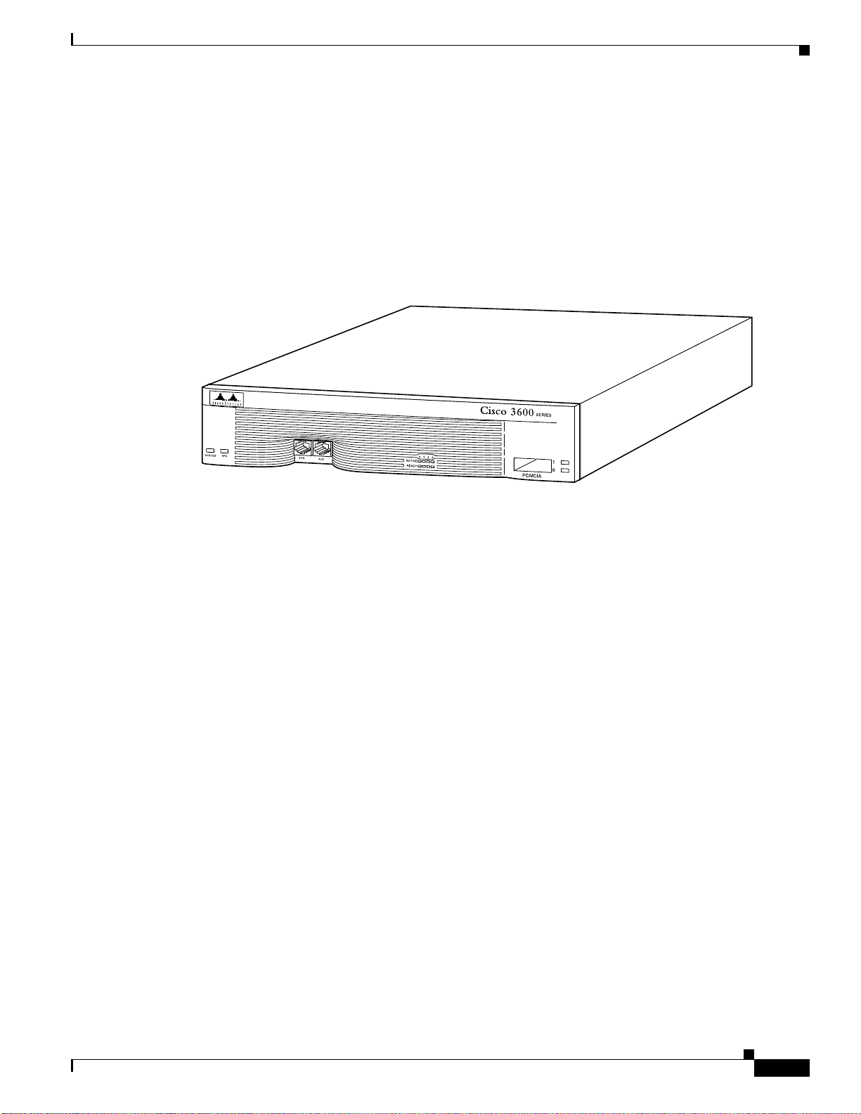
Figure 1-1 Front Panel of the Cisco 3620 Router
H7336
Cisco 3631
The Cisco 3631 router includes these additional features:
• High-performance 240-MHz PMC-Sierra RM7061A RISC processor
• One 10/100 Ethernet port
• Two slots for network modules
• One compact Flash memory card slot
• One Advanced Integration Module (AIM) slot
• 2 WIC/VIC slots
• Can be installed in a 19- or 23-inch rack or on a desk
Figure 1-2 Front Panel of the Cisco 3631 Router
SERIES
1-2
62574
Cisco 3600 Series Routers Hardware Installation Guide
OL-2056-05
Page 3
Chapter 1 Overview of Cisco 3600 Series Routers
Cisco 3640
The Cisco 3640 router includes these additional features:
• High-performance 100-MHz RISC processor
• Four slots for network modules
• Can be installed in a 19-, 23-, or 24-inch rack, or on a desk
• Can receive DC power from the Cisco Redundant Power System (RPS)
Figure 1-3 Front Panel of the Cisco 3640 Router
Hardware Features
Cisco 3660
H7221
The Cisco 3660 router includes these additional features:
• High-performance 225-MHz RISC processor installed on a removable mainboard tray
• Six slots for hot swapping similar network modules
• Can be installed in a 19- or 23-inch rack, or on a desk
• Dual redundant, hot-swappable power supplies (second power supply is optional)
• Hot-swappable fan cage used to cool the chassis
• One or two onboard, autosensing, 10/100 Fast Ethernet interfaces
• Supports two Advanced Integration Modules (AIMs)
OL-2056-05
Cisco 3600 Series Routers Hardware Installation Guide
1-3
Page 4
Hardware Features
ETH 0
ETH 3
ETHERNET
4E
ETH 2 ETH 1
123
ACT
LINK
0
CN/LP RXC
SERIAL 3 SERIAL 2
SERIAL 1 SERIAL 0
RXD TXC
TXD
CN/LP RXC RXD TXC TXD
CN/LP RXC RXD
TXC TXD
CN/LP RXC RXD TXC TXD
EN
SERIAL
4T
VOICE
2V
V0
V1
EN
HIGH SPEED SERIAL
1HSSI
HS
TD
TC
RD
RC
LB/CN
Chapter 1 Overview of Cisco 3600 Series Routers
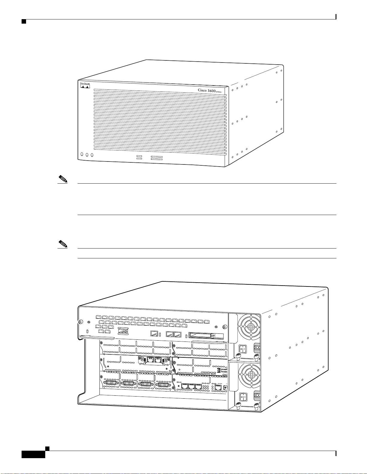
Figure 1-4 Front Panel of the Cisco 3660 Router
17325
SYSTEM
PS1
PS2
ACTIVE
FE
READY
0/0
0/1
1
2
3
4
5
6
Note The Cisco 3660 router platform consists of two router models: Cisco 3661 and Cisco 3662. The
Cisco 3661 router with one Fast Ethernet interface (part number CISCO3661-xC) is shown in
Figure 1-5, and the Cisco 3662 router with two Fast Ethernet interfaces (part number CISCO3662-xC or
CISCO3662-xC-CO) is shown in Figure 1-6.
Figure 1-5 and Figure 1-6 show Cisco 3660 AC power supplies installed. The DC power supplies differ
in appearance but occupy the same bays in the router.
Note In this publication, references to Cisco 3660 routers include both Cisco 3661 and Cisco 3662 models.
Figure 1-5 Cisco 3661 Router with One Fast Ethernet Interface
1-4
VCC OK
SYSTEM
Cisco 3600 Series Routers Hardware Installation Guide
FDX
VIC
FXS
IN USE
1
SEE MANUAL BEFORE INSTALLATION
LINK
100Mbps
IN USE
0
1
0
30255
OL-2056-05
Page 5
Chapter 1 Overview of Cisco 3600 Series Routers
ETH 0
ETH 3
ETHERNET
4E
ETH 2 ETH 1
123
ACT
LINK
0
CN/LP RXC
SERIAL 3 SERIAL 2
SERIAL 1 SERIAL 0
RXD TXC
TXD
CN/LP RXC RXD TXC TXD
CN/LP RXC RXD
TXC TXD
CN/LP RXC RXD TXC TXD
EN
SERIAL
4T
VOICE
2V
V0
V1
EN
HIGH SPEED SERIAL
1HSSI
HS
TD
TC
RD
RC
LB/CN
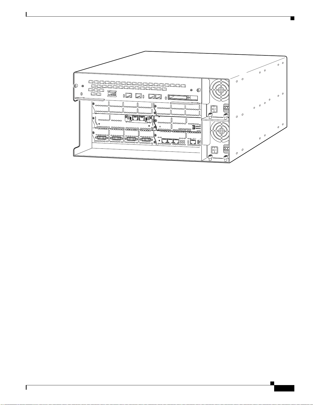
Figure 1-6 Cisco 3662 Router with Two Fast Ethernet Interfaces
VCC OK
SYSTEM
Modules and Interface Cards
FDX
LINK
100Mbps
VIC
FXS
IN USE
1
SEE MANUAL BEFORE INSTALLATION
FDX
LINK
100Mbps
IN USE
0
1
0
30254
Modules and Interface Cards
The latest information on network modules, WAN interface cards (WICs), voice interface cards (VICs),
and advanced integration modules (AIMs) is available online and on the documentation CD-ROM.
• For information on installing network modules, refer to the following documents:
–
Quick Start Guide: Network Modules for Cisco 2600 Series, Cisco 3600 Series, and Cisco 3700
Series Routers
–
Cisco Network Modules Hardware Installation Guide
• For information on installing WICs and VICs, refer to the following documents:
–
Quick Start Guide: Interface Cards for Cisco 1600, 1700, 2600, 3600, and 3700 Series
–
Cisco Interface Cards Hardware Installation Guide
• For information on installing AIMs, refer to the following documents:
–
AIM Installation Quick Start Guide: Cisco 2600, 3600, and 3700 Series
–
Installing Advanced Integration Modules in Cisco 2600 Series, Cisco 3600 Series, and Cisco
3700 Series Routers
OL-2056-05
Cisco 3600 Series Routers Hardware Installation Guide
1-5
Page 6

Memory
Memory
Memory Types
Chapter 1 Overview of Cisco 3600 Series Routers
This section describes the various types of memory that may be present in a Cisco 3600 series router.
Cisco 3600 series routers support the following types of memory:
• DRAM or SDRAM—Stores the running configuration and routing tables, and is used for packet
buffering by the router’s network interfaces. The Cisco IOS software executes from DRAM.
• Nonvolatilerandom-access memory (NVRAM)—Storesthesystem configurationfile and thevirtual
configuration register. (For more information, see Appendix C, “Configuration Register.”)
• Flash memory—Stores the operating system software image. You can also add Flash memory on
PCMCIA cards and compact Flash cards, depending on the router.
• EPROM-based memory—Stores the ROM monitor, which allows you to boot an operating system
software image from Flash memory or PCMCIA memory.
Memory Installation Documentation
For information about installing DRAM, SDRAM, NVRAM, and Flash memory SIMMs, refer to the
following hardware configuration note:
• Upgrading System Memory in Cisco 3600 Series Routers
For information about installing Flash memory PCMCIA cards, refer to the following hardware
configuration note:
• Installing and Configuring Flash Memory Cards in Cisco 3600 Series Routers
For information about installing compact Flash memory cards, refer to the following hardware
configuration note:
• Installing and Formatting Cisco 2691, Cisco 3631 and Cisco 3700 Compact Flash Memory Cards
Memory Specifications
Table 1-1 through Table 1-4 list processor and memory specifications for the routers.
Table 1-1 Cisco 3620 Router Processor and Memory Specifications
Description Specification
Processor 80-MHz IDT1 R4700 RISC
DRAM (main plus shared) 4 to 64 MB
NVRAM 32 KB
Flash memory (SIMM) 4 to 32 MB
Flash memory (PCMCIA) 2 to 40 MB
Boot ROM 512 KB
1. IDT = Integrated Device Technology.
1-6
Cisco 3600 Series Routers Hardware Installation Guide
OL-2056-05
Page 7

Chapter 1 Overview of Cisco 3600 Series Routers
Table 1-2 Cisco 3631 Router Processor and Memory Specifications
Description Specification
Processor 240-MHz PMC-Sierra RM7061A
SDRAM (main plus shared) 64 to 256 MB
NVRAM 55 KB
Flash memory
(compact Flash)
Boot ROM 512 KB
Table 1-3 Cisco 3640 Router Processor and Memory Specifications
Description Specification
Processor 100-MHz IDT R4700 RISC
DRAM (main plus shared) 4 to 128 MB
NVRAM 128 KB
Flash memory (SIMM) 4 to 32 MB
Flash memory (PCMCIA) 2 to 40 MB
Boot ROM 512 KB
Memory
RISC processor
32 to 128 MB
Table 1-4 Cisco 3660 Router Processor and Memory Specifications
Description Specification
Processor 225-MHz QED RM5271
SDRAM (main plus shared) 32 to 256 MB
NVRAM 128 KB
Flash memory (SIMM) 8 to 64 MB
Flash memory (PCMCIA) 2 to 40 MB
Boot ROM 512 KB
OL-2056-05
Cisco 3600 Series Routers Hardware Installation Guide
1-7
Page 8

Interface Numbering
Interface Numbering
Cisco 3620 and Cisco 3640 Interfaces
Each individual network interface on a Cisco 3620 or Cisco 3640 router is identified by a slot number
and a unit number.
Slot Numbering
The Cisco 3620 or Cisco 3640 router chassis contains two or four slots in which you can install modules.
You can install any module into any availableslot in the chassis. For Cisco 3620 and Cisco 3640 routers,
the slots are numbered as follows:
• Slot 0 is at the bottom right (as viewed from the rear of the chassis), near the power supply.
• Slot 1 is at the bottom left.
• Slot 2 is at the top right, above slot 0.
• Slot 3 is at the top left, above slot 1.
Chapter 1 Overview of Cisco 3600 Series Routers
Unit Numbering
Cisco 3600 series routers have unit numbers that identify the interfaces on the modules and WAN
interface cards installed in the router. Unit numbers begin at 0 for each interface type, and continue from
right to left and (if necessary) from bottom to top. Modules and WAN interface cards are identified by
interface type, slot number, followed by a forward slash (/), and then the unit number; for example,
Ethernet 0/0.
Figure 1-7 shows a router with a 2E 2-slot module in slots 0 and 1. Two serial WAN interface cards are
installed in the module in slot 0. One serial and one ISDN BRI WAN interface card are installed in the
module in slot 1.
Figure 1-7 Cisco 3600 Series Unit Numbers
BRI 1/0
3
2E
W1
2W
B1
B2
SEE MANUAL BEFORE INSTALLATION
ACT
LINK
1
ETHERNET 1
thernet 1/1
Serial 1/0
ACT
BRI
NT1
ACT
LINK
ETHERNET 0
Ethernet 1/0
Serial 0/1
W0
2E
W1
2W
ACT
SERIAL
AUI
EN
ETHERNET 1
Ethernet 0/1
ACT
SERIAL
ACT
Ethernet 0/0
Serial 0/0
ACT
LINK
ETHERNET 0
ACT
2
W0
SERIAL
AUI
EN
INPUT 100-240VAC 50/60HZ 3.0-1.5 AMPS
Power supply
41182
1-8
Cisco 3600 Series Routers Hardware Installation Guide
OL-2056-05
Page 9

Chapter 1 Overview of Cisco 3600 Series Routers
Voice Interface Numbering
Voice interfaces are numbered as follows:
interface-type chassis-slot/voice-module-slot/voice-interface
For example, Slot 1, voice network module slot 0, is referred to as voice 1/0/0 (closest to chassis slot 0).
Cisco 3631 Interfaces
Each individual interface (port) on a Cisco 3631 router is identified by number as described in the
following sections.
WAN and LAN Interface Numbering
The Cisco 3631 router chassis contains the following WAN and LAN interface types:
• One built-in FastEthernet LAN interface
• Two slots in which you can install WAN interface cards (WICs)
• Two single-width slots (slot 1 and slot 2) in which you can install single-width network modules
The numbering format is Interface-type Slot-number/Interface-number. Two examples are:
• FastEthernet 0/0
• Serial 1/2
The slot numbers are as follows:
• 0 for all built-in interfaces
• 0 for all WIC interfaces
• 1 for interfaces in the lower network module slot
• 2 for interfaces in the upper network module slot
Interface (port) numbers begin at 0 for each interface type, and continue from right to left and (if
necessary) from bottom to top.
Figure 1-8 shows an example of interface numbering on a Cisco 3631 router with:
• A WIC in each WIC slot (containing interfaces serial 0/0 and serial 0/1 in physical slot W0, and
interface serial 0/2 in physical slot W1)
• A 32-port asynchronous network module in slot 1 (containing interfaces serial 1/0 through serial
1/31)
• An alarm interface controller network module in slot 2 (internally connected to interface serial 2/0)
• One built-in Ethernet 10/100 interface—FastEthernet 0/0
Interface Numbering
OL-2056-05
Cisco 3600 Series Routers Hardware Installation Guide
1-9
Page 10

Interface Numbering
Chapter 1 Overview of Cisco 3600 Series Routers
Figure 1-8 Interface Numbering—Example
Internal connections to serial 2/0
Serial 0/0
Serial 0/2
AIC-64
CONN 1
CONN 2
ASYNC
31
27
30
26
29
ASYNC 24-31
25
28
24
15
11
14
10
13
ASYNC 8-15
9
12
8
CONN 3
CONN 4
STAT
ASYNC 16-23
ASYNC 0-7
EN
TD
RD
LP
AL
SEE MANUAL BEFORE INSTALLATION
EN
23
19
22
18
21
17
20
16
7
3
6
2
5
1
4
0
CD
DSU
56K
Serial 0/1
SEE MANUAL BEFORE INSTALLATION
62052
FastEthernet 0/0
Serial 1/0 to 1/7
Serial 1/16 to 1/23
Serial 1/8 to 1/15
Console/AUX
ports
Serial 1/24 to 1/31
Note The slot number for all WIC interfaces is always 0. (The W0 and W1 slot designations are for physical
slot identificationonly.)Interfacesinthe WICs are numbered from right to left, starting with 0/0 for each
interface type, regardless of which physical slot the WICs are installed in. Some examples are:
–
If slot W0 is empty and slot W1 contains a 1-port serial WIC, the interface in the WIC is
numbered serial 0/0.
–
If slot W0 contains a 2-port serial WIC and slot W1 contains a 1-port serial WIC, the interfaces
in physical slot W0 are numbered serial 0/0 and serial 0/1, and the interface in physical slot W1
is numbered serial 0/2.
–
If slot W0 contains a 2-port serial WIC and slot W1 contains a 1-port BRI WIC, the interfaces
in physical slot W0 are numbered serial 0/0 and serial 0/1, and the interface in physical slot W1
is numbered BRI 0/0.
1-10
Cisco 3600 Series Routers Hardware Installation Guide
OL-2056-05
Page 11

Chapter 1 Overview of Cisco 3600 Series Routers
ETH 0
ETH 3
ETHERNET
4E
ETH 2 ETH 1
123
ACT
LINK
0
CN/LP RXC
SERIAL 3 SERIAL 2
SERIAL 1 SERIAL 0
RXD TXC
TXD
CN/LP RXC RXD TXC TXD
CN/LP RXC RXD
TXC TXD
CN/LP RXC RXD TXC TXD
EN
SERIAL
4T
VOICE
2V
V0
V1
EN
HIGH SPEED SERIAL
1HSSI
HS
TD
TC
RD
RC
LB/CN
Cisco 3660 Interfaces
Each individual network interface on a Cisco 3600 series router is identified by a slot number and port
number.
Slot Numbering
The Cisco 3660 router chassis has six network module slots. Each network module slot accepts a variety
of network module interface cards, supporting a variety of LAN and WAN technologies. Figure 1-9
shows the locations of the network module slots.
Figure 1-9 Cisco 3660 Slot Numbers
Interface Numbering
VCC OK
SYSTEM
FDX
LINK
100Mbps
VIC
FXS
IN USE
1
SEE MANUAL BEFORE INSTALLATION
FDX
LINK
100Mbps
IN USE
0
1
0
82775
Slot 6
Slot 4
Slot 2
Slot 0
Slot 5
Slot 3
Slot 1
Modules and WAN interface cards are identified by interface type, slot number, followed by a forward
slash (/), and then the port number; for example, Ethernet 0/0.
• Slot 0 contains fixed Fast Ethernet ports and is located at the top of the chassis.
• Slot 1 through Slot 6 accept up to six network modules.
Port numbers usually begin at 0 for each interface slot, and continue from right to left and, if necessary,
from bottom to top. However, interface numbering for the Cisco 3660 series routers and for Ethernet and
Token Ring network modules with two WAN interface card slots differs in the following ways:
• WAN interface card slot numbers always appear as slot 0, even if the interface card is installed in
the slot labeled W1.
• WAN interface cards are numbered dynamically, starting with the first card installed. For example:
–
If slot W0 is empty and slot W1 contains a 1-port serial WAN interface card, the interface
number would be serial 0/0.
–
If slot W0 contains a 2-port serial WAN interface card and slot W1 contains a 1-port serial
interface card, serial 0/0 and 0/1 would reside in slot W0 and serial 0/2 would reside in slot W1.
OL-2056-05
Cisco 3600 Series Routers Hardware Installation Guide
1-11
Page 12

System Specifications
Voice Interface Numbering
Voice interfaces are numbered differently from WAN interfaces. Voice interfaces are numbered as
follows:
interface-type chassis-slot/voice-module-slot/voice-interface
If you have a 4-channel voice network module installed in slot 1 of your router, the voice interfaces will
be as follows:
• Chassis-slot 1, voice-network-module-slot 0, voice-interface 0, referred to as voice 1/0/0 (closest to
chassis-slot 0)
• Chassis-slot 1, voice-network-module-slot 0, voice-interface 1, referred to as voice 1/0/1
• Chassis-slot 1, voice-network-module-slot 1, voice-interface 0, referred to as voice 1/1/0
• Chassis-slot 1, voice-network-module-slot 1, voice-interface 1, referred to as voice 1/1/1 (farthest
from chassis-slot 0)
System Specifications
Chapter 1 Overview of Cisco 3600 Series Routers
Table 1-5 through Table 1-8 contain Cisco 3600 series system specifications.
Table 1-5 Cisco 3620 Router System Specifications
Description Specification
Dimensions (H x W x D) 1.75 x 17.5 x 13.5 inches (4.4 x 44.5 x 34.3 cm), one rack unit in height
Weight 23 lb (10.45 kg), maximum including chassis and two network modules
Input voltage, AC power
supply
Current
Frequency
Input surge current (AC)
Input rating, DC power
supply
Current
Input surge current (DC)
Power dissipation 95 W (maximum)
Console and auxiliary ports RJ-45 connector
Operating humidity 5 to 95%, noncondensing
Operating temperature 32 to 104°F (0 to 40°C)
Nonoperating temperature –40 to 185°F (–40 to 85°C)
Noise level 45 dBA (maximum)
Regulatory compliance FCC Part 15 Class A. For additional compliance information, refer to
Safety compliance UL 60950; CAN/CSA C22.2 No. 60950-00; IEC 60950;
100 to 240 VAC, autoranging
2.0A
47 to 64 Hz
50A, one cycle
–3 to –75 VDC
5.0 A
65 A, 250 ms
the Cisco 2600 Series, Cisco 3600 Series, and Cisco 3700 Series
Regulatory Compliance and Safety Information document that
accompanied the router.
AS/NZS 3260; TS001
1-12
Cisco 3600 Series Routers Hardware Installation Guide
OL-2056-05
Page 13

Chapter 1 Overview of Cisco 3600 Series Routers
Table 1-6 Cisco 3631 Router System Specifications
Description Specification
Dimensions (H x W x D) 3.46 x 17.07 x 11.20 inches (8.78 x 45.36 x 28.45 cm), two rack units
Weight 15 lb (6.8 kg)
Input voltage, AC power
supply
Current
Frequency
Input surge current (AC)
Input rating, DC power
supply
Operational between
Current
Input surge current (DC)
Power dissipation 105 W (maximum)
Console and auxiliary ports RJ-45 connector
Operating humidity 5 to 95%, noncondensing
Operating temperature 32 to 104°F (0 to 40°C)
Nonoperating temperature –40 to 185°F (–40 to 85°C)
Noise level 45 dBA (maximum)
Regulatory compliance FCC Part 15 Class A. For additional compliance information, refer to
Safety compliance UL 60950; CAN/CSA C22.2 No. 60950-00; IEC 60950;
System Specifications
in height
100 to 240 VAC, autoranging
2.0 A
47 to 63 Hz
50 A, one cycle
–48 to –60 VDC
–48 to –60 VDC
4.0 A
50 A, 250 ms
the Cisco 2600 Series, Cisco 3600 Series, and Cisco 3700 Series
Regulatory Compliance and Safety Information document that
accompanied the router.
AS/NZS 3260; TS001
OL-2056-05
Cisco 3600 Series Routers Hardware Installation Guide
1-13
Page 14

System Specifications
Chapter 1 Overview of Cisco 3600 Series Routers
Table 1-7 Cisco 3640 Router System Specifications
Description Specification
Dimensions (H x W x D) 3.44 x 17.5 x 15.8 inches (8.7 x 44.5 x 40.0 cm), two rack units in height
Weight 30 lb (13.6 kg), including chassis and four modules
Input voltage, AC power
100 to 240 VAC, autoranging
supply
Current
Frequency
Input surge current (AC)
Input rating, DC power
2.0 A
47 to 64 Hz
50 A, one cycle
–38 to –75 VDC
supply
Current
Input surge current (DC)
5.0 A
65 A, 250 ms
Power dissipation 220 W (maximum)
Console and auxiliary ports RJ-45 connector
Operating humidity 5 to 95%, noncondensing
Operating temperature 32 to 104°F (0 to 40°C)
Nonoperating temperature –40 to 185°F (–40 to 85°C)
Noise level 51.9 dBA (maximum)
Regulatory compliance FCC Part 15 Class A. For additional compliance information, refer to
the Cisco 2600 Series, Cisco 3600 Series, and Cisco 3700 Series
Regulatory Compliance and Safety Information document that
accompanied the router.
Safety compliance UL 60950; CAN/CSA C22.2 No. 60950-00; IEC 60950; AS/NZS 3260;
TS001
1-14
Cisco 3600 Series Routers Hardware Installation Guide
OL-2056-05
Page 15

Chapter 1 Overview of Cisco 3600 Series Routers
Table 1-8 Cisco 3660 Router System Specifications
Description Specification
Dimensions (H x W x D) 8.75 x 17.5 x 11.5 inches (22.1 x 44.5 x 29.1 cm), five rack units in
Weight 48 lb (21.8 kg), including chassis, six modules, and two power supplies
Input voltage, AC power
supply
(dual, redundant)
Current
Frequency
Input surge current (AC)
Input rating, DC power
supply
(dual, redundant)
Operational between
Current
Input surge current (DC)
Power dissipation 380 W (maximum)
Console and auxiliary ports RJ-45 connector
Operating humidity 5 to 95%, noncondensing
Operating temperature 32 to 104°F (0 to 40°C)
Nonoperating temperature –40 to 185°F (–40 to 85°C)
Noise level 50 dBA
Regulatory compliance FCC Part 15 Class A. For additional compliance information, refer to
Safety compliance UL 60950; CAN/CSA C22.2 No. 60950-00; IEC 60950; AS/NZS 3260;
Regulatory Compliance
height
100 to 240 VAC, autoranging
4.0 A/2.0 A
47 to 63 Hz
50 A, half-cycle
–48 to –60 VDC
–36 to –72 VDC
10.0 A
50 A, 10 ms
the Cisco 2600 Series, Cisco 3600 Series, and Cisco 3700 Series
Regulatory Compliance and Safety Information document.
TS001
Regulatory Compliance
For compliance information, refer to the Cisco 2600 Series, Cisco 3600 Series, and Cisco 3700 Series
Regulatory Compliance and Safety Information document that accompanied your router.
OL-2056-05
Cisco 3600 Series Routers Hardware Installation Guide
1-15
Page 16

Regulatory Compliance
Chapter 1 Overview of Cisco 3600 Series Routers
1-16
Cisco 3600 Series Routers Hardware Installation Guide
OL-2056-05
 Loading...