

Page 1
In-wall
loudspeaker
User-Guide
Serial No
Builder
wafer1-iw
™
wafer2-iw
™
Page 2

Product Support
For product support, accessories or servicing advice, please contact a
PMC authorised distributor. See www.pmc-speakers.com.
Guarantee Certificate
Please take a few moments to complete the warranty card at the back of this booklet
or register at www.pmcloudspeaker.com/guarantee. It records the purchase and
provides you, the customer, an opportunity to make suggestions and provide feedback
directly to PMC.
Company Details
PMC LIMITED
43-45 CRAWLEY GREEN ROAD LUTON LU2 0AA UK
T +44 00 (0)870 4441044 F +44 00 (0)870 4441045
email sales@promonitor.co.uk web www.pmc-speakers.com
PMC USA LLC
17932 SKY PARK CIRCLE DR., SUITE A IRVINE, CA 92614
T 949-861-3350 F 949-861-3352
email sales@pmc-speakers.us web www.pmc-speakers.com
' 2006 PMC. All rights reserved.
This document should not be construed as a commitment on the part of PMC.
The information it contains is subject to change without notice. PMC assumes no responsibility for errors that may appear within this document.
CE Conformity PMC passive loudspeakers conform to CE Directive LVD 73/23/EEC and EMC 89/336/EEC
Page 3

Contents
Introduction
The ATLTMApproach
Our Attention to Detail
General Guidelines
Unpacking
wafer-iw
TM
installation examples
wafer-iwTMcontrol - High frequency adjustment
wafer-iwTMControl - TT T echnology
TM
UsingTT T echnology
TM
StealthBaffle
TM
& H-Line ATL
TM
Wall/Ceiling installation of the wafer-iw
TM
wafer-iw
TM
in-ceiling Installation (cont.)
wafer-iw
TM
in-ceiling Installation examples
wafer-iw
TM
in-ceiling Installation examples (cont.)
Connections
Service
Specification Table
Specification diagrams
Suggested Associate Loudspeakers
Inspection Certificate
GUARANTEE CERTIFICATE - Part 1
GUARANTEE CERTIFICATE - Part 2
Help us improve
26
25
24
23
22
21
20
19
18
17
16
15
14
13
12
11
10
9
8
7
6
5
4
Loudspeaker User-Guide
Page 4

wafer-iw
™
Loudspeaker User-Guide
4
Introduction
The wafer™series of in & on-wall loudspeakers are a true breakthrough and encompass
PMC s award-winning professional monitoring heritage in a slim and elegant design,
ideally suited to match modern d cor and lifestyles.
PMC products are to be found in every demanding environment, from broadcast and
major film scoring to CD and DVD mastering. No other manufacturer can rival the
accumulated technical knowledge and high level of engineering excellence PMC has
developed over many years at the peak of professional monitoring. This expertise has
been encapsulated in the development and production of the PMC consumer range.
The wafer
™
series is ideal for stereo or all channels of a surround system. The wafer™has
been engineered with an identical tonal balance and similar dispersion characteristics
to all PMC models, thereby any combination will afford seamless integration and a
perfect audio picture. The professionally proven TLE1 active subwoofer can also
partner any of the range to provide the ultimate in low frequency power and
musicality.
See page 22 of this user guide & www.pmc-speakers.com
Closing the loop between the studio and the home
Page 5

The DB1+ ATL
TM
The ATL
TM
Approach
PMC ATL“(Advanced Transmission Line) enclosures have taken loudspeaker design to
the highest level. A PMC transmission line design utilises sophisticated cabinet
construction, proprietary drive units and patented absorption materials and
techniques. The benefits are enormous compared to the relatively simple sealed and
ported models currently available elsewhere.
The main driver is placed at one end of a long tunnel (the transmission line), which is
heavily damped with absorbent acoustic material. This material is specified to absorb
the upper bass and higher frequencies that radiate from the rear of the main driver.
The lowest frequencies, which remain in phase, then emerge from the large vent at
the end of the line, which essentially acts as a second driver. One advantage to this
approach is that the air pressure loading the main driver is maintained, thus controlling
the driver over a wide frequency range, which in turn significantly reduces distortion.
A spin-off from the lack of distortion is that the upper bass and midrange is not masked
by harmonic distortion residing in the very low frequencies. The result is PMC’s
characteristic transparent midrange and fast, attacking bass notes, all with
outstanding clarity. A further advantage of the transmission line approach is a cabinet
that produces a higher SPL and lower bass extension than a ported or sealed design of
a similar size, even if identical drivers were used. Moreover, as the loading on the main
driver is maintained at all volumes, the frequency response also remains consistent
regardless of listening level. Neither casual late night listening nor prolonged monitoring
sessions have to be conducted at high volumes to achieve maximum bass response,
a characteristic that is especially suited for both the home user and recording
professional alike.
wafer-iw
™
Loudspeaker User-Guide
5
Page 6

wafer-iw
™
Loudspeaker User-Guide
6
Our Attention to Detail
All PMC loudspeakers are hand-built in the U.K. using individual components that are
matched to our reference model; this includes the structural integrity of every cabinet
and the testing and recording of each component. This guarantees it will be within our
strict tolerances and ensures your purchase sounds identical to the original design.
Each completed loudspeaker then undergoes a set of objective and subjective
measurements - frequency response sweeps ensure that the design meets our
exacting performance criteria, and then listening tests are conducted against the
reference model using a wide variety of material, from a benchmark BBC speech test
to classical music, pop and rock.
Page 7

wafer-iw
™
Loudspeaker User-Guide
7
General Usage Guidelines
Read these instructions and keep them in a safe place for further reference.
Heed all electrical safety warnings, including any on the loudspeakers
themselves.
Do not use the loudspeakers near water.
Clean only with a dry, lint-free, cloth.
Do not install near any heat sources such as radiators, ovens or other
equipment that produce excessive heat.
High volume audio signals, however short their duration, have the potential to
cause hearing damage. Use care when setting the system volume level to
ensure playback sound pressure levels remain within comfortable limits.
Refer all servicing to qualified service personnel. Servicing is required when the
apparatus has been damaged in any way or exhibits a distinct or sudden
change of operation or performance.
The wafer
™
series is not magnetically shielded, please ensure that they are
positioned at least 1 metre/3 feet away from items that could be damaged by
stray magnetic fields. Conventional glass tube (CRT) televisions and computer
monitors together with media such as floppy discs, cassettes and videotapes
are particularly susceptible.
PMC has made efforts to provide accurate installation information and good
quality fixings, PMC Ltd / PMC USA LLC cannot be held responsible or liable for
injuries or property damage - direct, indirect or consequential - arising out of
use or inability to use this product safely and properly.
9
8
765
4
3
2
1
Page 8

wafer-iw
™
Loudspeaker User-Guide
8
Unpacking
Please retain your packaging for future use as all PMC cartons are durable,
reusable and can be employed to safely transport your loudspeakers should
they be relocated.
Much of the packing is constructed from recyclable materials, so if you are to
dispose of it please do so in an environmentally friendly manner.
Check list
1 x Printed card positioning template.
1 x Perforated grille. (paintable)
1 x Grille removing hook
1 x Paint/dust mask (Within the grille - remove before operation)
1 x Cabinet including 8 concealed spring lugs and integrated
paintable bezel/frame
Page 9
wafer-iw
™
Loudspeaker User-Guide
9
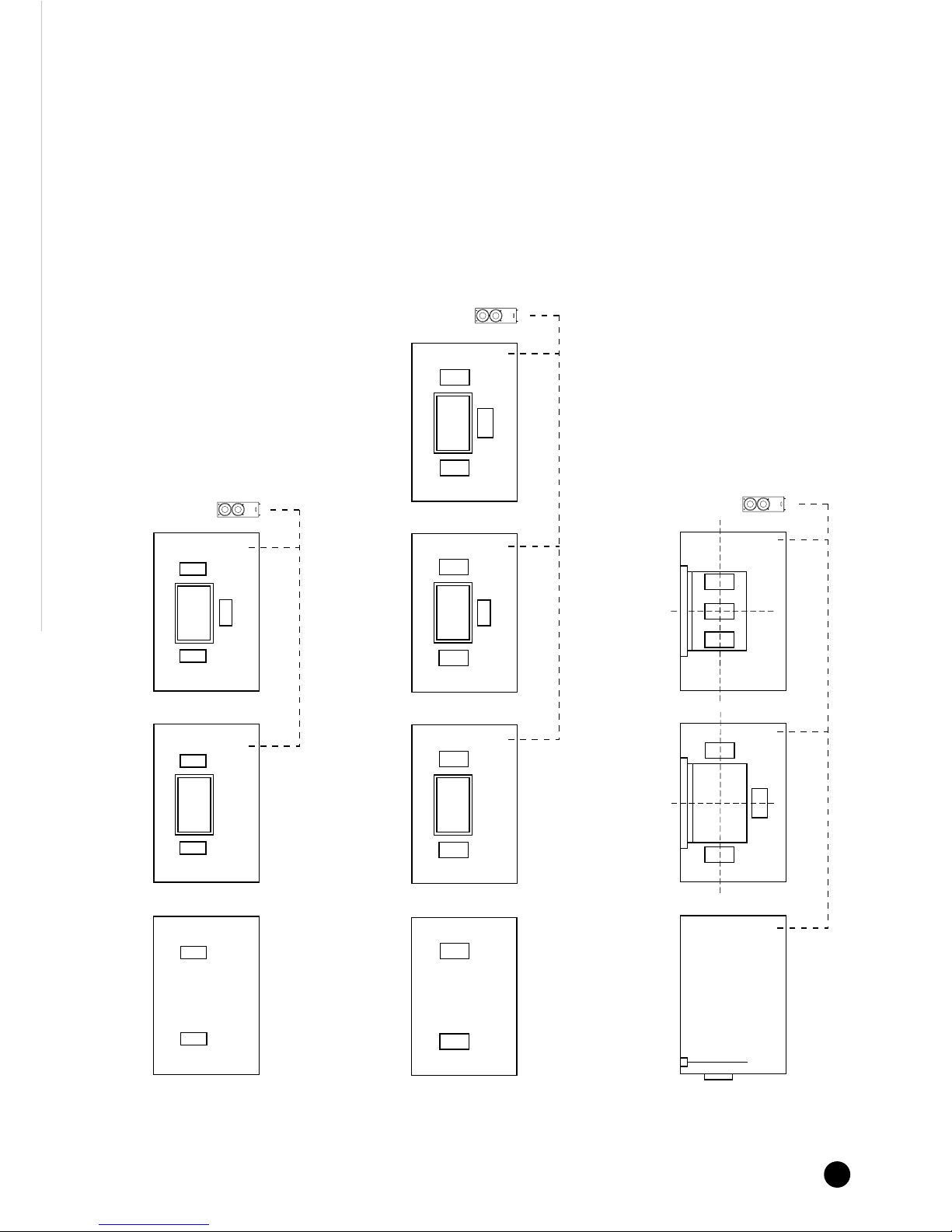
wafer
™
series installation examples
Mixing and matching any of
the wafer
™
series and PMC s
consumer range creates a
supreme and unbeatable
surround system.
See page 22
wafer1
TM
stereo
wafer1
TM
stereo with 42" plasma
wafer1
TM
Left, Centre, Right
with 42" plasma
wafer1
TM
series installation examples
Optional TLE1 sub
wafer2
TM
stereo wafer2
TM
stereo with 42" plasma wafer2
TM
Left, Right, wafer1
TM
Centre,
with 42" plasma
wafer2
TM
Left, Centre, Right,
with 42" plasma
wafer 2
TM
series installation examples
Optional TLE1 sub
Side view showing waferTMbehind screen
Installation example with
non-perforated projection screen
Installation example with perforated
projection screen
wafer
TM
series installation examples with projection screens
Optional TLE1 sub
Page 10

wafer-iw
™
Loudspeaker User-Guide
10
wafer-iw
™
control
- High frequency adjustment
Fine adjustment for perfect definition.
The wafer-iw
“
sports a three position tweeter level control to ensure a perfect tonal
integration into even the most difficult environment.
FLAT
The FLAT setting is perfect for the majority of installations.
HF-
Rooms with very little soft furnishings, like kitchens, can emphasise the high frequency,
so a reduction may be desirable by moving the switch to the HF- position.
HF+
Conversely a very heavily furnished absorbent room or if the wafer-iw“is placed
behind a perforated projector screen may need a small high frequency boost to
improve definition. Set to the HF+ position.
control
HF +
HF -
FLAT
VERTICAL
BEAM-UP
HORIZONTAL
Select from the
3 switch positions
These are not hard and fast rules, as every
listening environment has its own distinct
acoustic. For the best results listen to the same
recording on each of the HF settings and
adjusting accordingly.
Page 11

wafer-iw
™
Loudspeaker User-Guide
11
wafer-iw™Control - TT Technology
™
Perfect response in either horizontal or vertical placement.
The wafer-iw
“
has a number of innovative features that will further enhance the quality
of sound so it can be sited where it is convenient and most pleasing to the eye.
The first of these is TT Technology
“
. This feature has two distinct benefits; firstly, either
tweeter can be switched to ensure a perfect response in either horizontal or vertical
placement.
control
Shading denotes
functioning drivers
Page 12

wafer-iw
™
Loudspeaker User-Guide
12
control
HF +
HF -
FLAT
VERTICAL
BEAM-UP
HORIZONTAL
Switch in the 'Beam-Up' position
Hi Zone
Lo Zone
Mid Zone
no need for beam up setting
Lo Zone
PMC s TT Technology™also allows for steerable image techniques which utilises
both tweeters to tilt the direction of the sound - a perfect solution if the wafer-iw
“
is placed much higher or lower than the listening position. It can also come into
play in some large environments when ceiling mounted. This mode should be tried
if the prime listening position is in no way directly below the wafer
™
but some 20
feet further forward or behind. Experimentation is best in this circumstance,
as room acoustics will play a large role in the result (see diagram below).
NB This mode will only function when the cabinet is in the correct horizontal
position with the wafer-iw
“
controls set as per the diagram above.
Using TT Technology
™
to ensure high performance when
placement is less than ideal.
6 metres
6 metres
6+ metres 6+ metres
Page 13

wafer-iw
™
Loudspeaker User-Guide
13
H-Line ATL
™
The ultra-shallow H-LineTM interior of each
cabinet is divided to create a long chamber,
which is in turn lined with special acoustic
materials. The result is an expansive, dynamic
soundstage, with the type of deep bass one
would only expect from a speaker many
times the size.
StealthBaffle
™
Standard in-wall and on-wall designs are
compromised by the large surface area of
their front baffle that surrounds the drive units.
This detrimental effect is best compared with
cupping your hands around your mouth whilst
speaking. PMC s acoustic specialists have
developed a unique, structured, absorbent
surface that prevents these unwanted
characteristic sound waves being reflected.
The drive units behave as though in free space
and concentrate pure, untainted audio
directly into the listening space.
StealthBaffle
™
Page 14

14
wafer-iw
™
Loudspeaker User-Guide
Safety instructions
Instructions detailed in this manual assumes the installer has the required skill and
knowledge of the tools, local building and fire regulations and is aware of the
environment within which the speakers will be installed. If in doubt, consult a
qualified professional.
Before attempting to make the wall cut-out by using the enclosed template, ensure
your actions do not detrimentally affect the structural integrity of the building nor disrupt
any hidden services or other installations. E.g. power, pipe work, air conditioning, signal
cable etc.
This wafer
™
may contain nuts.
Before embarking on the installation ensure the kit is complete.
Check list
1 x Printed card positioning template.
1 x Perforated grille. (paintable)
1 x Grille removing hook
1 x Paint/dust mask (Within the grille - remove before operation)
1 x Cabinet including 8 concealed spring lugs and integrated paintable bezel/frame
Ensure correct orientation for optimum performance. (See pages 12,16 &17)
Produce the wall cut-out using the supplied template. (See Safety instructions
before taking action)
Check inside the cavity for obstructions that will impede the spring lugs on the
sides of the cabinet.
Tighten up the spring lug bolts that correspond with the spring lugs intended for
use until they appear fully from rebate in the sides of the cabinet. It is ideal if all 8
can be utilised, but if there is obstructions e.g. studwork etc. The recommended
minimum is 4.
4
3
2
1
Wall/Ceiling installation of the wafer-iw
™
Page 15

wafer-iw
™
Loudspeaker User-Guide
15
Note the wall thickness, and tighten the spring lug bolts so the spring lugs move
close to the position they will remain once the cabinet is secured. This will avoid
aching arms and swearing.
Ensure the unused spring lugs are returned to their rest position and do not
protrude from the cabinet rebate. Failure to do so may result in rattling.
Connect loudspeaker cables (See connections, page No.18)
Install the cabinet through the prepared hole ensuring the cable are safely inside
the cavity. The spring lugs should click into place and temporarily secure the
cabinet from falling out from the opening.
Tighten the appropriate number of spring lug bolts required until the bezel/frame
and cabinet are fully secure.
Make any adjustments to the wafer
™
control switches - Vertical, Horizontal,
HF+, HF- etc
Remove the Dust/paint mask if painting is complete and there is no risk from dust.
Gently press the grille into place.
Removal of the wafer-iw
TM
from the wall
To remove the wafer-iw“from the wall/ceiling. Remove the grille starting from one
edge using the grille removing hook. Slacken all 8 spring lug bolts; this will retract
the lugs into the rebate freeing the cabinet. Do this operation gently.
PMC has made efforts to provide accurate installation information and good quality fixings, PMC Ltd / PMC USA LLC
cannot be held responsible or liable for injuries or property damage - direct, indirect or consequential arising out of use or inability to use this product safely and properly.
12
11
10
9
8
7
6
5
Wall/Ceiling installation of the wafer-iwTM(Cont.)
Page 16

wafer-iw
™
Loudspeaker User-Guide
16
Switch position set to vertical
Shading denotes
functioning drivers
Beams/Joists
wafer-iw
™
in-ceiling Installation examples
Depending on the direction of the woodwork e.g. beams or joists that form the ceiling
structure, it will be necessary to orientate the wafer-iw
“
in the following manor to
ensure the highest quality response.
These diagrams are a view from the floor looking directly up at the ceiling.
An identical view if you were lying on your back in bed. Not that we are insinuating
you are lazy, but it is a view you will be familiar with.
Page 17

wafer-iw
™
Loudspeaker User-Guide
17
control
Switch position set to horizontal
Shading denotes
functioning drivers
Beams/Joists
NB
If the wafer-iw’s
“
have been installed within the ceiling of a large room or the
listening position is more than 20 feet away; experiment with those distant speakers
using the beam-up function. If the acoustics of the room allow, the image will be
more obvious in this setting.
wafer-iw™in-ceiling Installation examples (Cont.)
Page 18

Connections
To avoid potential damage, please ensure that your power amplifier(s) or receiver is
turned off before making or breaking any loudspeaker connections.
When selecting cables for use with your PMC loudspeakers, ensure that their
construction is of a high enough quality to withstand the rigours of everyday use and
comply with local regulations.
Bare, tinned, or 4mm banana plug terminated cable can be accommodated by the
wafer-iw
“
sprung binding posts.
To use the spring terminal function - push the terminal lightly until the two 4.3mm holes
of the inner and outer housings correspond. Place the cable through the hole and
release the terminal. Then test the cable is secure and there is no loose cable strand
protruding that may cause shorting.
It is of vital importance to observe the polarity markings and
maintain positive-to-positive and negative-to-negative
connections from amplifier or receiver to the wafer-iw“.
The wafer-iw
“
terminals are colour-coded to aid in their
identification, positive terminals are red, negative
terminals are black.
Customisation
Both the bezel & grille can be repainted to match the desired interior scheme.
When painting ensure the paint is applied as a thin coat and does not reduce the
pore size of the grille. Failure to do so will inhibit the performance of the wafer-iw
“
.
While painting, or when there is dust in the atmosphere, leave the Paint/Dust mask
in place not forgetting to remove it before operation.
NB: Do not attempt to paint the main cabinet or front baffle of the wafer-iw
“
.
-
+
-
+
wafer™ back panel
wafer-iw
™
Loudspeaker User-Guide
18
Page 19

wafer-iw
™
Loudspeaker User-Guide
19
Service
We are confident that your wafer-iw“loudspeakers will afford many years of troublefree listening of the highest order, but in the unlikely event that one or more requires
repair, our unique manufacturing procedure, wherein the precise value of each
component together with the response of the system as a whole is recorded, will
ensure that any replaced parts will exactly match the performance of those originally
included within each individual loudspeaker.
For any issues that might arise or for advice and service requirements, the primary point
of contact should be your knowledgeable and authorised PMC dealer/distributor.
If you do not have a local representative please see www.pmc-speakers.com and
click on distribution.
Important Note: Please do not return any products to PMC directly without first
contacting our support department and obtaining a Return Authorisation Number.
Page 20

wafer-iw
™
Loudspeaker User-Guide
20
wafer1-iw
™
wafer2-iw
™
Freq response 50Hz-25kHz 40Hz-25kHz
Sensitivity 87dB 1w 1m 90dB 1w 1m
Impedance 8 Ohms 8 Ohms
Drive Units LF 140mm (5.5 inches) LF 170mm (6.5 inches)
HF 2 x 27mm Soft dome HF 2 x 27mm Soft dome
Input connectors 1 pair - Sprung & 4mm sockets 1 pair - Sprung & 4mm sockets
Dimensions H x W x D H x W x D
Cabinet 500 x 235 x 100mm 575 x 355 x 100mm
(19.7 x 9.3 x 4 inches) (22.6 x 14 x 4 inches)
Cabinet with grille 550 x 285 x 107mm 625 x 405 x 107mm
(21.65 x 11.22 x 4.21 inches) (24.61 x 15.94 x 4.21 inches)
Weight 5.5kg (12.1 lbs) 7.1kg (15.62 lbs)
Grille & frame/bezel White, satin, RAL 9016 "
Cabinet colour Black, satin, RAL 9005 "
Suggested cutout Suggested cutout
Specifications
www.pmc-speakers.com
Positioning Template
Cut Out (max.)
Height 504mm - (19.84")
Width 239mm - (9.40")
Cabinet Dimensions
Height 500mm - (19.69")
Width 235mm - (9.25")
Depth 100mm - (3.94")
Spring lug protrudes 25mm/1"
from the cabinet side
Frame Dimensions
Height 550mm - (21.65")
Width 285mm - (11.22")
Spring lug position
protrudes by
25mm/1 inch
239mm - 9.40"
504mm
19.84"
Spring
lug bolt
Spring
lug bolt
Spring
lug bolt
Spring
lug bolt
Spring
lug bolt
Spring
lug bolt
Spring
lug bolt
Spring
lug bolt
50mm
1.97"
50mm
1.97"
www.pmc-speakers.com
Positioning Template
Cut Out (max.)
Height 579mm - (22.80")
Width 359mm - (14,13")
Cabinet Dimensions
Height 575mm - (22.64")
Width 355mm - (13,98")
Depth 100mm - (3.94")
Spring lug protrudes 25mm/1"
from the cabinet side
Frame Dimensions
Height 625mm - (24.61")
Width 405mm - (15.94")
Spring lug position
protrudes by
25mm/1 inch
359mm - 14.13"
579mm
22.80"
Spring
lug bolt
Spring
lug bolt
Spring
lug bolt
Spring
lug bolt
Spring
lug bolt
Spring
lug bolt
Spring
lug bolt
Spring
lug bolt
50mm
1.97"
50mm
1.97"
Page 21

wafer-iw
™
Loudspeaker User-Guide
21
405mm/19.94"
625mm
24.61"
550mm
21.66"
285mm/11.22"
wafer 1-iw
™
Front
wafer 1-iw
™
Rear
wafer 2-iw
™
Front
wafer 2-iw
™
Rear
120mm/4.72"
140mm/5.51"
235mm/9.25"
81mm
3.19"
142mm
5.59"
500mm
19.69"
50mm
1.97"
50mm
1.97"
50mm
1.97"
142mm
5.59"
81mm
3.19"
167mm/6.57"
187mm/7.36"
355mm/13.98"
575mm
22.64"
50mm
1.97"
100mm
3.94"
96mm
3.78"
Page 22

wafer-iw
™
Loudspeaker User-Guide
22
Suggested Associate Loudspeakers
PMC manufacture a large selection of loudspeakers and sub-woofers to meet a range
of budgets and uses, from compact, audiophile designs to large studio monitors.
The following products make ideal companions to create an unbeatable
surround system.
DB1M-C+
(Magnetically screened
Horizontal centre channel)
TB2M-C+
(Larger, Magnetically
screened Horizontal centre)
TB2+
(Larger, Two way monitor)
DB1+
(Compact two way monitor)
wafer1-iw
™
(Two Way in-wall monitor)
wafer 2-iw
™
(Larger Two way in-wall monitor)
TLE1
(Active Subwoofer)
FB1+
(Two Way, Floorstanding monitor)
GB1
(Compact, Two Way,
Floorstanding monitor)
OB1
(Larger, Three Way
Floorstanding monitor)
wafer 1
™
(Two way on-wall monitor)
wafer 2
™
(Larger, Two way on-wall monitor)
Page 23

wafer-iw
™
Loudspeaker User-Guide
23
Inspection Certificate
Every component that appears in a PMC product is measured, tested, matched and
recorded by hand. This analysis also applies to the final product with the addition of
the ultimate test of the human ear. We simply listen to every product we make to
ensure you receive an identical replica of the reference model.
Enclosure finish
Assembly & Wiring
Driver Installation
Enclosure seal test
Level - Frequency test
Impedance - frequency test
Listening test 1
Listening test 2
Final inspection
Paint/Dust mask included
Grille hook included
User Guide included
all above checked by
Date
Page 24

GUARANTEE CERTIFICATE - Part 1
Your Copy
Please complete and retain this page
Thank you for purchasing a PMC product. Please read all points carefully before sending any
product to PMC Limited.
If a product is returned to us and subsequently is found to have no fault it will be subject to a
minimum testing and labour charge of £50.00 plus an additional £18.00 carriage for its return.
(UK customers only)
Proof of purchase is required for any claim covered by this guarantee.
This product is guaranteed for a period of 5 years from the date of purchase or date of receipt if
received by mail, provided that the bottom section of this form is detached and returned to PMC
within ten days of purchase or receipt. The guarantee covers defects due to faulty materials or
workmanship but does not cover defects arising from accidental damage, misuse or wear and
tear. The guarantee is void if any attempt has been made by persons not authorised by PMC to
dismantle or repair any part of the product.
Should you have a claim under this guarantee, you can either send the product to the address at
the bottom of this form or return it to the dealer from whom the product was purchased.
Please ensure that it is properly packaged as this guarantee does not cover damage in transit.
Please note that the cost of the carriage to PMC is not covered by the guarantee.
Returned products that are defective will be repaired or replaced at the discretion of PMC
and returned free of charge.
Please allow 14 working days for return of guarantee repairs.
This guarantee does not effect your consumer rights under statutory law.
This guarantee certificate is only valid in the United Kingdom.
Type of product
Serial Nos
Date of purchase
Dealers Name
Address
Town
County
Postcode
Dealers Telephone No
PMC LIMITED 43-45 Crawley Green Road Luton LU2 0AA UK T +44 (0) 870 4441044 F +44 (0) 870 4441045
wafer-iw
™
Loudspeaker User-Guide
24
Page 25

wafer-iw
™
Loudspeaker User-Guide
25
Help us improve
our products
see over
GUARANTEE CERTIFICATE - Part 2
Our Copy
Please complete and return this section -
or complete the on-line version at www.pmcloudspeaker.com/guarantee
Product
Serial Nos
Date of purchase
Your name
Address
Town
County
Zip/Postcode
Dealers Name
PMC Limited 43-45 Crawley Green Road Luton UK LU2 0AA
T (0)870 4441044 F (0)870 4441045
Page 26

wafer-iw
™
Loudspeaker User-Guide
26
We value all our client s comments. Please take a moment to help us improve:
If there is one thing we should change, what would it be?
Is there a product/finish missing from our range? If so, what would it be?
If you wish to write your very own review of your PMC product, please attach it with the
guarantee certificate - CD/Floppy/Hard copy. We will include as many as we can on our
website page - Clients Reviews. See www.pmc-speakers.com
Many thanks
Help us Improve - Your Comments
Page 27

notes
Page 28

PMC LIMITED
43-45 CRAWLEY GREEN ROAD LUTON LU2 0AA UK
T +44 00 (0)870 4441044 F +44 00 (0)870 4441045
email sales@promonitor.co.uk web www.pmc-speakers.com
PMC USA LLC
17932 SKY PARK CIRCLE DR., SUITE A IRVINE, CA 92614
T 949-861-3350 F 949-861-3352
email sales@pmc-speakers.us web www.pmc-speakers.com
 Loading...