

Page 1

查询1991611供应商
TEMUX/TEMAP/TECT3 (PM8315, PM5365, PM4328) Driver Manual
PM8315, PM5365, PM4328
TEMUX/TEMAP/TECT3
T1/E1 FRAMER, VT/TU MAPPER, M12/M13 MUX
DRIVER MANUAL
PROPRIETARY AND CONFIDENTIAL
R
ELEASE
SSUE 2: AUGUST, 2001
I
Proprietary and Confidential to PMC-Sierra, Inc., and for its Customers’ Internal Use
Document ID: PMC-1991611, Issue 2
Page 2

TEMUX/TEMAP/TECT3 (PM8315, PM5365, PM4328) Driver Manual
ABOUT THIS MANUAL AND TEMUX/TEMAP/TECT3
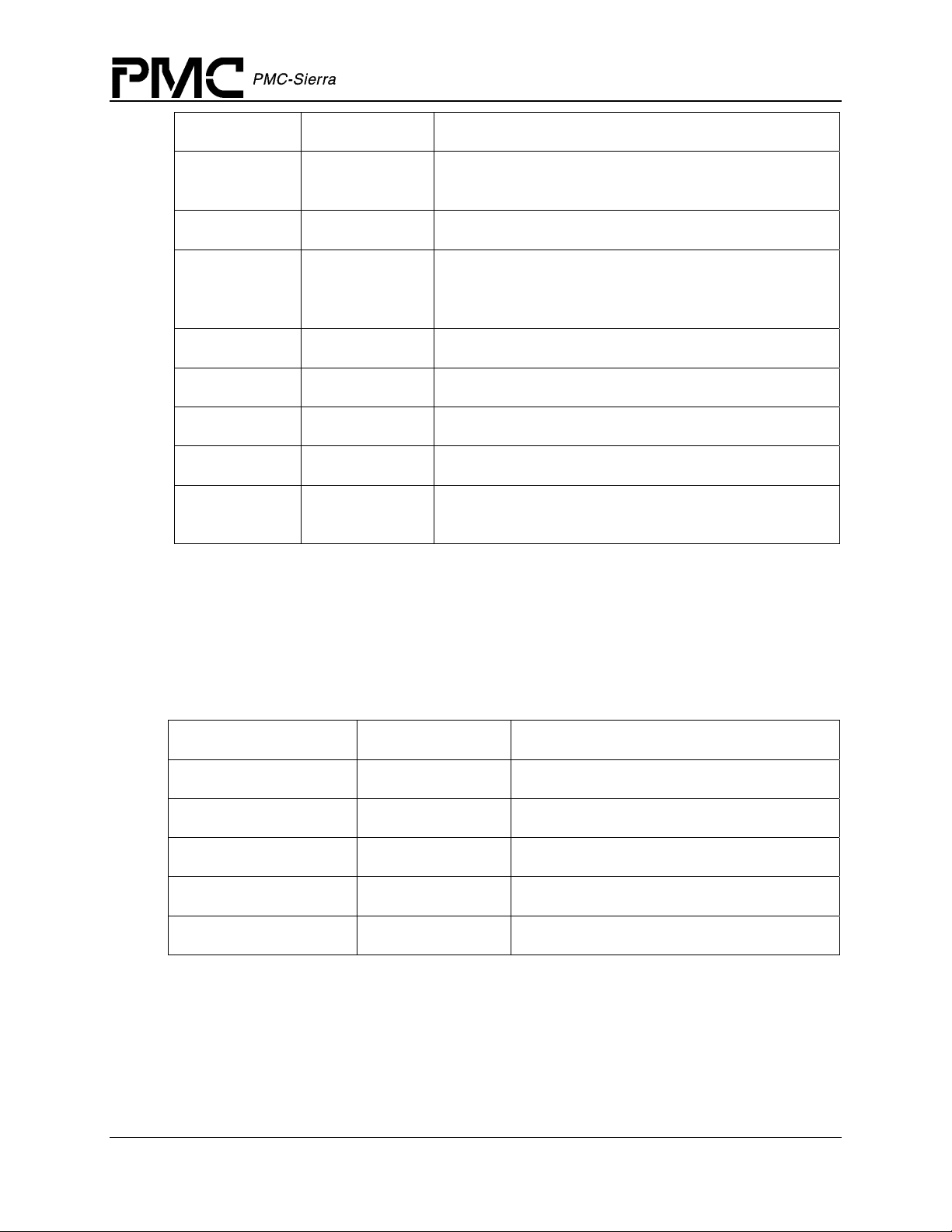
This manual describes the device driver for the TEMUX/TEMAP/TECT3 devices. Since the
TEMAP and TECT3 devices contain a subset of the features provided by the TEMUX device, the
same driver is used for all. Briefly the differences between the devices is as follows, please refer
to the devices respective data sheets for more information.
Table 1: Device Differences
Device
TEMUX Yes Yes Yes Yes
TEMAP No Yes Yes Yes
TECT3 Yes No Yes No
This manual describes the driver’s functions, data structures, and architecture. It focuses on the
driver’s interfaces to your application, Real-Time Operating System, and to the
TEMUX/TEMAP/TECT3 device. It also describes in general terms how to modify and port the
driver to your software and hardware platform.
28 T1, 21 E1
Framers
VT1.5/VT2/T
U-11/TU-12
Sonet/SDH
Mapping
M13 MUX
with DS3
Framer
Sonet/SDH
DS3 Mapper
Audience
This manual is written for people who need to:
· Evaluate and test the TEMUX/TEMAP/TECT3 devices
· Modify and add to the TEMUX/TEMAP/TECT3 driver’s functions
· Port the TEMUX/TEMAP/TECT3 driver to a particular platform.
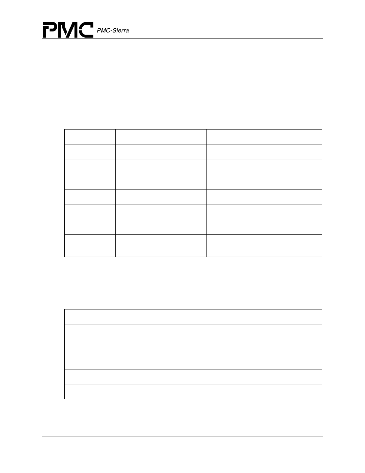
References
For more information about the TEMUX/TEMAP/TECT3 driver, see the driver’s release notes.
For more information about the TEMUX/TEMAP/TECT3 device, see the documents listed in the
table below and any related errata documents.
Proprietary and Confidential to PMC-Sierra, Inc., and for its Customers’ Internal Use 2
Document ID: PMC-1991611, Issue 2
Page 3
TEMUX/TEMAP/TECT3 (PM8315, PM5365, PM4328) Driver Manual
Table 2: Related Documents
Document Number Document Name
PMC-1981411 TEMAP High Density VT/TU Mapper and M13 Multiplexer Short
Form Data Sheet
PMC-1981125 High Density T1/E1 Framer with Integrated VT/TU Mapper and M13
Multiplexer Telecom Standard Product Data Sheet
PMC-2011596 High Density T1/E1 Framer with Integrated M13 Multiplexer
Telecom Standard Product Datasheet
Note: Ensure that you use the document that PMC-Sierra issued for your version of the device
and driver.
Revision History
Issue No. Issue Date Details of Change
Issue 1 February 2000 Document created
Issue 2 July 2001 Added documentation to support TEMAP and TECT3 devices.
Added more detail to porting section.
Added init profile information and some missing API.
Proprietary and Confidential to PMC-Sierra, Inc., and for its Customers’ Internal Use 3
Document ID: PMC-1991611, Issue 2
Page 4

TEMUX/TEMAP/TECT3 (PM8315, PM5365, PM4328) Driver Manual
Legal Issues
None of the information contained in this document constitutes an express or implied warranty by
PMC-Sierra, Inc. as to the sufficiency, fitness or suitability for a particular purpose of any such
information or the fitness, or suitability for a particular purpose, merchantability, performance,
compatibility with other parts or systems, of any of the products of PMC-Sierra, Inc., or any
portion thereof, referred to in this document. PMC-Sierra, Inc. expressly disclaims all
representations and warranties of any kind regarding the contents or use of the information,
including, but not limited to, express and implied warranties of accuracy, completeness,
merchantability, fitness for a particular use, or non-infringement.
In no event will PMC-Sierra, Inc. be liable for any direct, indirect, special, incidental or
consequential damages, including, but not limited to, lost profits, lost business or lost data
resulting from any use of or reliance upon the information, whether or not PMC-Sierra, Inc. has
been advised of the possibility of such damage.
The information is proprietary and confidential to PMC-Sierra, Inc., and for its customers’
internal use. In any event, you cannot reproduce any part of this document, in any form, without
the express written consent of PMC-Sierra, Inc.
© 2001 PMC-Sierra, Inc.
PMC-1991611 (P1), ref PMC-990551 (P1)
The technology discussed is protected by one or more of the following Patents:
U.S. Patent No. 5,835,545 5,973,977 5,343,482
Relevant patent applications and other patents may also exist.
Contacting PMC-Sierra
PMC-Sierra, Inc.
105-8555 Baxter Place Burnaby, BC
Canada V5A 4V7
Tel: (604) 415-6000
Fax: (604) 415-6200
Document Information: document@pmc-sierra.com
Corporate Information: info@pmc-sierra.com
Technical Support: apps@pmc-sierra.com
Web Site: http://www.pmc-sierra.com
Proprietary and Confidential to PMC-Sierra, Inc., and for its Customers’ Internal Use 4
Document ID: PMC-1991611, Issue 2
Page 5

TEMUX/TEMAP/TECT3 (PM8315, PM5365, PM4328) Driver Manual
TABLE OF CONTENTS
About this Manual and TEMUX/TEMAP/TECT3........................................................................... 2
Audience ..........................................................................................................................2
References.......................................................................................................................2
Revision History ...............................................................................................................3
Legal Issues .....................................................................................................................4
Contacting PMC-Sierra .................................................................................................... 4
Table of Contents ..........................................................................................................................5
List of Figures................................................................................................................................9
List of Tables ............................................................................................................................... 10
1 Introduction ............................................................................................................................12
2 Software Architecture.............................................................................................................13
2.1 Driver External Interfaces ..................................................................................................... 13
Application Programming Interface................................................................................ 13
Real-Time RTOS Interface............................................................................................. 14
Driver Hardware Interface.............................................................................................. 14
2.2 Main Components.................................................................................................................14
Module and Device Management .................................................................................. 15
Driver Library..................................................................................................................16
Interrupt Processing .......................................................................................................16
3 Software State Description.....................................................................................................18
3.1 Module States ....................................................................................................................... 18
Start: TMX_MOD_START .............................................................................................. 19
Idle: TMX_MOD_IDLE ................................................................................................... 19
Ready: TMX_MOD_READY .......................................................................................... 19
3.2 Device States........................................................................................................................19
Start: TMX_START ......................................................................................................... 19
Present: TMX_PRESENT ..............................................................................................20
Active: TMX_ACTIVE ..................................................................................................... 20
Inactive: TMX_INACTIVE............................................................................................... 20
3.3 Processing Flows .................................................................................................................20
Module Management .....................................................................................................20
Device Management ......................................................................................................21
3.4 Interrupt Servicing ................................................................................................................22
Calling temuxISR ........................................................................................................... 23
Calling temuxDPR .......................................................................................................... 23
3.5 Polling Servicing ...................................................................................................................24
4 Data Structures ......................................................................................................................26
Proprietary and Confidential to PMC-Sierra, Inc., and for its Customers’ Internal Use 5
Document ID: PMC-1991611, Issue 2
Page 6

TEMUX/TEMAP/TECT3 (PM8315, PM5365, PM4328) Driver Manual
4.1 Constants..............................................................................................................................26
4.2 Data Structures.....................................................................................................................26
4.3 Structures Passed by the Application ...................................................................................26
Module Initialization Vector ............................................................................................ 26
Device Initialization Vector............................................................................................. 27
Device Initialization Profile .............................................................................................28
Preset Profiles................................................................................................................29
Interrupt-Service Routine Mask Vector .......................................................................... 30
Mask Sub-structures ......................................................................................................30
Device Diagnostic Structures .........................................................................................36
4.4 Structures in the Driver’s Allocated Memory......................................................................... 37
Module Data Block ......................................................................................................... 37
Module Status Block.......................................................................................................38
Device Data Block.......................................................................................................... 38
Device Status Block .......................................................................................................40
DSB Sub-structures .......................................................................................................41
4.5 Global Variables....................................................................................................................43
4.6 Structures Passed through RTOS Buffers............................................................................ 43
Interrupt Status Vector....................................................................................................43
ISV Sub-structures .........................................................................................................44
Deferred-Processing Routine Vector .............................................................................48
5 Application Programming Interface........................................................................................ 49
5.1 Module Initialization .............................................................................................................. 49
Opening Modules: temuxModuleOpen ..........................................................................49
Closing Modules: temuxModuleClose............................................................................ 49
5.2 Module Activation .................................................................................................................50
Starting Modules: temuxModuleStart ............................................................................. 50
Stopping Modules: temuxModuleStop ...........................................................................50
5.3 Device Initialization ............................................................................................................... 51
Adding Devices: temuxAdd............................................................................................51
Deleting Devices: temuxDelete......................................................................................52
Initializing Devices: temuxInit ......................................................................................... 52
Resetting Devices: temuxReset.....................................................................................53
Deactivating Devices: temuxDeActivate ........................................................................ 53
Activating Devices: temuxActivate................................................................................. 54
Add Initialization Profile: temuxAddInitProfile ................................................................54
Get Initialization Profile: temuxGetInitProfile ................................................................. 55
Delete Initialization Profile: temuxDeleteInitProfile ........................................................ 55
Updating a device: temuxUpdate...................................................................................56
5.4 Device Reading and Writing .................................................................................................57
Reading Registers: temuxRead ..................................................................................... 57
Writing Registers: temuxWrite........................................................................................ 57
Reading Framer Registers: temuxReadFR.................................................................... 58
Writing Framer Registers: temuxWriteFR ...................................................................... 58
Reading DS2/MX12 Multiplexer Registers: temuxReadMX ..........................................59
Proprietary and Confidential to PMC-Sierra, Inc., and for its Customers’ Internal Use 6
Document ID: PMC-1991611, Issue 2
Page 7

TEMUX/TEMAP/TECT3 (PM8315, PM5365, PM4328) Driver Manual
Writing DS2/MX12 Multiplexer Registers: temuxWriteMX .............................................60
Reading Indirect Registers: temuxReadInd ................................................................... 60
Writing Indirect Registers: temuxWriteInd...................................................................... 61
Reading from Register Blocks: temuxReadBlock .......................................................... 63
Writing to Register Blocks: temuxWriteBlock................................................................. 64
Reading Mapper Registers: temuxReadMapper (TEMUX/TEMAP only) ......................64
Writing Mapper Registers: temuxWriteMapper (TEMUX/TEMAP only) ......................... 65
DS3-HDLC Service: temuxLinkDataDS3 ....................................................................... 66
T1-HDLC Service: temuxLinkDataT1 (TEMUX/TECT3 Only)........................................66
5.5 Interrupt Service Functions................................................................................................... 67
Getting Mask Registers: temuxGetMask .......................................................................67
Setting Mask Registers: temuxSetMask ........................................................................ 68
Clearing Mask Registers: temuxClearMask................................................................... 68
Polling Interrupt Registers: temuxPoll............................................................................69
Interrupt Service: temuxISR...........................................................................................69
Interrupt Processing: temuxDPR ...................................................................................70
Configure ISR: temuxISRConfig .................................................................................... 70
5.6 Alarms, Status and Statistics Functions ............................................................................... 71
Retrieving Statistical Counts: temuxGetStats................................................................. 71
Clearing Statistical Counts: temuxClearStats................................................................. 71
5.7 Device Diagnostics ...............................................................................................................72
Clearing/Setting Mapper Loopbacks: temuxLoopMapper (TEMUX/TEMAP only) ........72
Clearing/Setting DS3 Devices Loopbacks: temuxLoopDS3 .......................................... 73
Clearing/Setting DS3 Bert Tests: temuxBertDS3........................................................... 73
Clearing or Setting Bert Framer: temuxBertFramer (TEMUX/TECT3 only)...................74
Clearing/Setting E1/T1 Framer Loopbacks: temuxLoopFramer (TEMUX/TECT3 only) 75
Clearing/Setting MX12 Devices Loopbacks: temuxLoopMX12 ..................................... 75
Clearing/Setting MX23 Devices Loopbacks: temuxLoopMX23 ..................................... 76
5.8 Callback Functions ............................................................................................................... 77
Reporting IO Events: sysTemuxCBackIO ......................................................................77
Reporting DS3 Events: sysTemuxCBackDS3................................................................ 77
Reporting Framer Events: sysTemuxCBackFramer ......................................................78
Reporting Mapper Events: sysTemuxCBackMapper (TEMUX/TEMAP only) ................ 78
6 Hardware Interface ................................................................................................................79
6.1 Platform Specific MACROs...................................................................................................79
Reading a Device Register: sysTemuxSafeRead ..........................................................79
Reading from Registers: sysTemuxReadReg................................................................ 79
Writing Register Values: sysTemuxWriteReg................................................................. 80
6.2 Interrupt Servicing ................................................................................................................80
General ISR Routines ....................................................................................................80
Installing Interrupt Handlers: sysTemuxISRHandlerInstall ............................................. 80
Invoking Interrupt Handlers: sysTemuxISRHandler .......................................................81
Removing Interrupt Handlers: sysTemuxISRHandlerRemove.......................................81
Installing DPRTask: sysTemuxDPRTaskInstall ..............................................................81
DPR Task: sysTemuxDPRTask ......................................................................................82
Removing DPRTask: sysTemuxDPRTaskRemove ........................................................ 82
7 RTOS Interface ......................................................................................................................83
Proprietary and Confidential to PMC-Sierra, Inc., and for its Customers’ Internal Use 7
Document ID: PMC-1991611, Issue 2
Page 8

TEMUX/TEMAP/TECT3 (PM8315, PM5365, PM4328) Driver Manual
7.1 Memory Allocation ................................................................................................................83
Allocating Memory: sysTemuxMemAlloc........................................................................ 83
Freeing Allocated Memory: sysTemuxMemFree............................................................ 83
7.2 Buffer Management ..............................................................................................................84
Starting Buffers: sysTemuxBufferStart............................................................................84
Getting DPV Buffers: sysTemuxDPVBufferGet.............................................................. 84
Getting ISV Buffers: sysTemuxISVBufferGet ................................................................. 85
Returning DPV Buffers: sysTemuxDPVBufferRtn ..........................................................85
Returning ISV Buffers: sysTemuxISVBufferRtn .............................................................85
Sending an ISV buffer to the DPR task: sysTemuxBufferSend .....................................85
Receiving an ISV buffer: sysTemuxBufferReceive.........................................................86
Stopping ISV/DPV Buffers: sysTemuxBufferStop ..........................................................86
8 Porting Drivers .......................................................................................................................87
8.1 Driver Source Files ............................................................................................................... 87
8.2 Driver Porting Procedures ....................................................................................................88
Step 1: Porting Driver RTOS Extensions .......................................................................88
Step 2: Porting Drivers to Hardware Platforms .............................................................. 90
Step 3: Porting Driver Application-Specific Elements..................................................... 90
Step 4: Building the Driver .............................................................................................91
Appendix A: Coding Conventions ............................................................................................... 92
Variable Type Definitions................................................................................................ 92
Naming Conventions...................................................................................................... 93
Macros ...........................................................................................................................93
Constants .......................................................................................................................94
Structures.......................................................................................................................94
Functions........................................................................................................................ 94
API Functions ................................................................................................................. 94
Porting Functions ...........................................................................................................94
Other Functions.............................................................................................................. 95
Variables.........................................................................................................................95
Appendix B: TEMUX/TECT3/TEMAP Error Codes.....................................................................96
Acronyms 98
List of Terms..............................................................................................................................100
Index 101
Proprietary and Confidential to PMC-Sierra, Inc., and for its Customers’ Internal Use 8
Document ID: PMC-1991611, Issue 2
Page 9

TEMUX/TEMAP/TECT3 (PM8315, PM5365, PM4328) Driver Manual
LIST OF FIGURES
Figure 1: Driver Interfaces................................................................................................. 13
Figure 2: Driver Architecture ............................................................................................. 15
Figure 3: State Diagram .................................................................................................... 18
Figure 4: Module Management Flow Diagram.................................................................. 21
Figure 5: Device Management Flow Diagram .................................................................. 22
Figure 6: Interrupt Service Model...................................................................................... 23
Figure 7: Polling Service Model ........................................................................................ 24
Proprietary and Confidential to PMC-Sierra, Inc., and for its Customers’ Internal Use 9
Document ID: PMC-1991611, Issue 2
Page 10

TEMUX/TEMAP/TECT3 (PM8315, PM5365, PM4328) Driver Manual
LIST OF TABLES
Table 1: Device Differences................................................................................................ 2
Table 2: Related Documents .............................................................................................. 3
Table 4: Module Initialization Vector: sTMX_MIV ............................................................. 27
Table 5: Device Initialization Vector: sTMX_DIV ..............................................................27
Table 6: Device Initialization Profile: sTMX_INIT_PROF.................................................. 28
Table 7: Preset Profiles: temuxInit .................................................................................... 29
Table 8: ISR Mask Vector: sTMX_MASK ......................................................................... 30
Table 9: IO Section Masks: struct tmx_mask_io............................................................... 30
Table 10: DS3 Section Masks: struct tmx_mask_ds3 ...................................................... 31
Table 11: MUX Section Masks: struct tmx_mask_mux .................................................... 31
Table 12: Framer Section Masks: struct tmx_mask_framer ............................................. 32
Table 13: Mapper Section Masks: struct tmx_mask_mapper (not
valid in TECT3 device).............................................................................................. 35
Table 14: PRGD configuration: sTMX_PRGD ..................................................................36
Table 15: PRBS configuration: sTMX_PRBS ................................................................... 36
Table 16: Module Data Block: sTMX_MDB ...................................................................... 37
Table 17: Module Status Block: sTMX_MSB .................................................................... 38
Table 18: Device Data Block: sTMX_DDB........................................................................ 39
Table 19: Device Status Block: sTMX_DSB ..................................................................... 40
Table 20: IO Section Status Block: struct tmx_dsb_io...................................................... 41
Table 21: DS3 Section Status Block: struct tmx_dsb_ds3................................................ 41
Table 22: MUX Section Status Block: struct tmx_dsb_mux............................................. 42
Table 23: Framer Section Status Block: struct tmx_dsb_framer ......................................42
Table 24: Mapper Section Status Block: struct tmx_dsb_mapper
(Not valid in TECT3) ................................................................................................. 42
Table 25: ISR Status Vector: sTMX_ISV ..........................................................................43
Table 26: IO Section ISR Status Vector: struct tmx_isv_io............................................... 44
Proprietary and Confidential to PMC-Sierra, Inc., and for its Customers’ Internal Use 10
Document ID: PMC-1991611, Issue 2
Page 11

TEMUX/TEMAP/TECT3 (PM8315, PM5365, PM4328) Driver Manual
Table 27: DS3 Section ISR Status Vector: struct tmx_isv_ds3 ........................................ 45
Table 28: MUX Section ISR Status Vector: struct tmx_isv_mux ...................................... 45
Table 29: Framer Section ISR Status Vector: struct
tmx_isv_framer.......................................................................................................... 45
Table 30: Mapper Section ISR Status Vector: struct
tmx_isv_mapper ........................................................................................................ 47
Table 31: Deferred-Processing Vector: sTMX_DPV......................................................... 48
Table 32: Table of Parameters: temuxReadInd ................................................................ 61
Table 33: Table of Parameters: temuxWriteInd ................................................................ 63
Table 34: Driver Source Files ........................................................................................... 87
Table 35: Variable Type Definitions .................................................................................. 92
Table 36: Naming Conventions......................................................................................... 93
Table 37: TEMUX/TECT3/TEMAP Error Codes ............................................................... 96
Proprietary and Confidential to PMC-Sierra, Inc., and for its Customers’ Internal Use 11
Document ID: PMC-1991611, Issue 2
Page 12

1 INTRODUCTION
The following sections of the TEMUX/TEMAP/TECT3 driver manual describe the
TEMUX/TEMAP/TECT3 device driver. The code provided throughout this document is written
in the ANSI C language. This has been done to promote greater driver portability to other
embedded hardware and Real-Time Operating System environments.
This driver can be used for the TEMUX/TEMAP/TECT3 devices. See Table 1 for a brief
description of the differences between these devices. To properly support the TEMAP device, use
the compile switch DEV_IS_TEMAP during compilation. To properly support the TECT3 device,
use the compile switch DEV_IS_TECT3 during compilation.
Section 2 of this document, Software Architecture, defines the software architecture of the
TEMUX/TEMAP/TECT3 device driver by including a discussion of the driver’s external
interfaces and its main components. The Data Structure information in Section 4 describes the
elements of the driver that either configure or control its behavior. Included here are the
constants, variables, and structures that the TEMUX/TEMAP/TECT3 device driver uses to store
initialization, configuration, and status information. Section 5 provides a detailed description of
each function that is a member of the TEMUX/TEMAP/TECT3 driver Application Programming
Interface (API). This section outlines: (1) function calls that hide device-specific details and (2)
application callbacks that notify the user of significant device events.
TEMUX/TEMAP/TECT3 (PM8315, PM5365, PM4328) Driver Manual
Introduction
For your convenience, this manual provides a brief guide to porting the TEMUX/TEMAP/TECT3
device driver to your hardware and RTOS platform (page 87). In addition, an Appendix
(beginning on page 92) and Index (page 101), provide you with useful reference information.
Proprietary and Confidential to PMC-Sierra, Inc., and for its Customers’ Internal Use 12
Document ID: PMC-1991611, Issue 2
Page 13
TEMUX/TEMAP/TECT3 (PM8315, PM5365, PM4328) Driver Manual
2 SOFTWARE ARCHITECTURE
This section describes the software architecture of the TEMUX/TEMAP/TECT3 device driver.
This includes a discussion of the driver’s external interfaces and its main components.
2.1 Driver External Interfaces
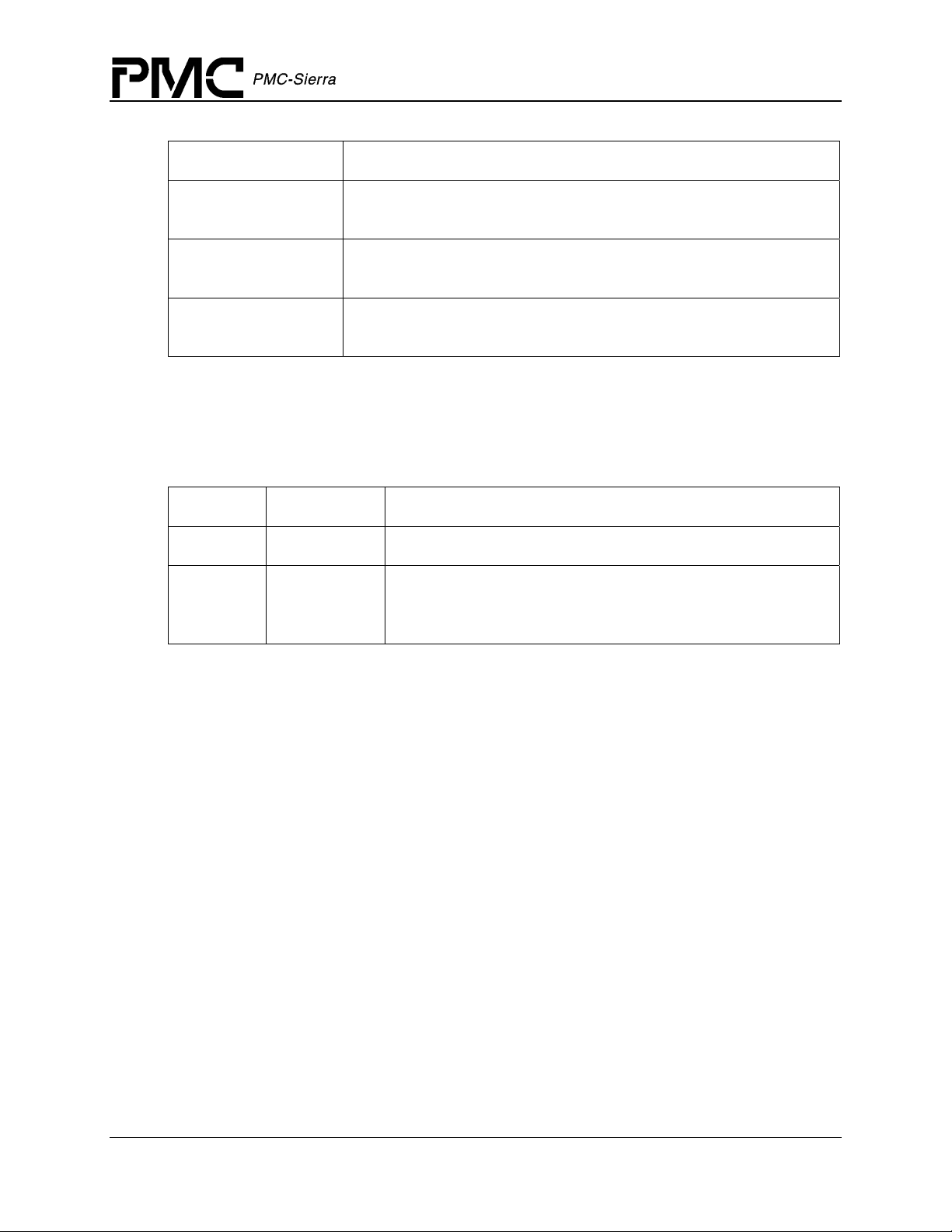
Figure 1 illustrates the external interfaces defined for the TEMUX/TEMAP/TECT3 device driver.
Figure 1: Driver Interfaces
Application
Software Architecture
Function Calls Application Callbacks
Service Callbacks
TEMUX/TEMAP/TECT3
Device Driver
Hardware
Interrupts
TEMUX/TEMAP/TECT3 Devices
Register
Accesses
Service Calls
RTOS
Application Programming Interface
The driver’s API is a collection of high level functions that can be called by application
programmers to configure, control, and monitor the TEMUX/TEMAP/TECT3 device, such as:
· Initializing the device
· Validating device configuration
· Retrieving device status and statistics information.
· Diagnosing the device
Proprietary and Confidential to PMC-Sierra, Inc., and for its Customers’ Internal Use 13
Document ID: PMC-1991611, Issue 2
Page 14

TEMUX/TEMAP/TECT3 (PM8315, PM5365, PM4328) Driver Manual
Software Architecture
The driver API functions use the driver library functions as building blocks to provide this system
level functionality to the application programmer. The driver API also consists of callback
functions that notify the application of significant events that take place within the device.
Real-Time RTOS Interface
The driver’s RTOS interface module provides functions that let the driver use RTOS services. The
RTOS interface functions perform the following tasks for the TEMUX/TEMAP/TECT3 driver:
· Allocate and de-allocate memory
· Manage buffers for the ISR and DPR
· Timer management
· Synchronization management
· Task management
You must modify the RTOS interface code to suit your RTOS environment.
Driver Hardware Interface
The TEMUX/TEMAP/TECT3 hardware interface provides functions that read from and write to
device-registers. The hardware interface also provides a template for an ISR that the driver calls
when the device raises a hardware interrupt. You must modify this function based on the interrupt
configuration of your system.
2.2 Main Components
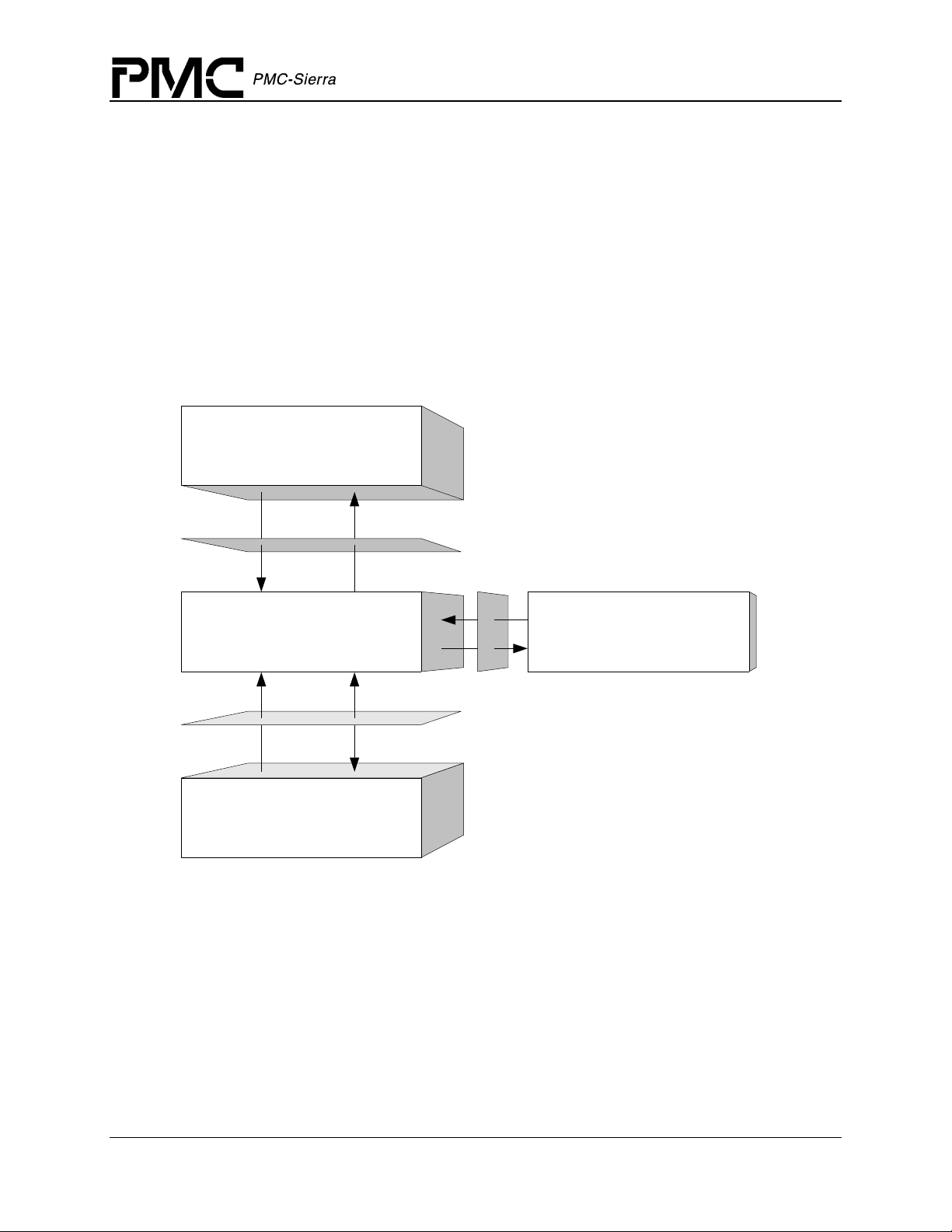
Figure 2 illustrates the top level architectural components of the TEMUX/TEMAP/TECT3 device
driver. This applies to both polled and interrupt driven operation. In polled operation the ISR is
called periodically. In interrupt operation the interrupt directly triggers the ISR.
The driver includes five main modules:
· Module and Device management
· Driver API
· Driver library
· Interrupt processing
Proprietary and Confidential to PMC-Sierra, Inc., and for its Customers’ Internal Use 14
Document ID: PMC-1991611, Issue 2
Page 15
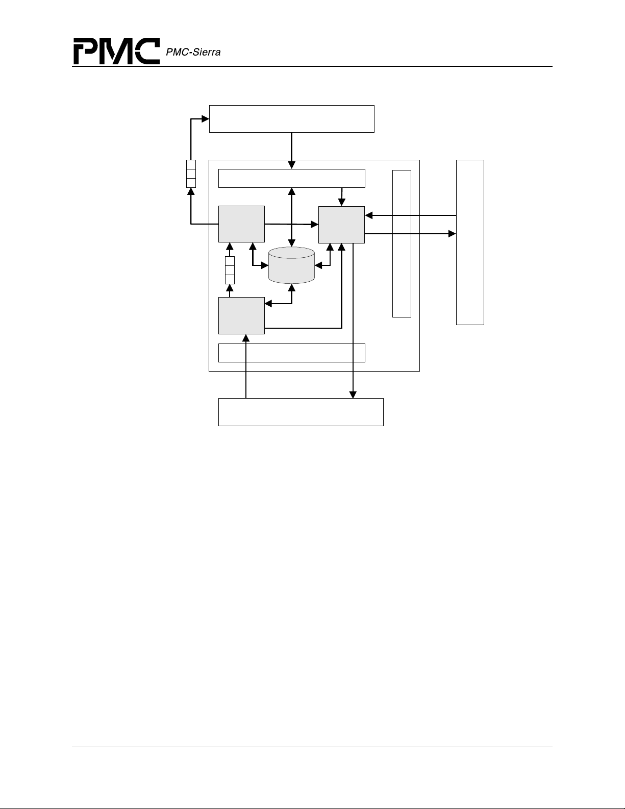
Figure 2: Driver Architecture
A
A
TEMUX/TEMAP/TECT3 (PM8315, PM5365, PM4328) Driver Manual
Software Architecture
Indication
Callbacks
Interrupt
Context
Deferred
Processing
Routine
Interrupt
Servicing
Routine
Hardware
Interrupts
pplication
Driver API
Module/Device
Data Block
Hardware Interface
Function
Calls
Driver
Library
Functions
R
T
Service
O
Callbacks
S
I
n
t
e
Service
r
Callbacks
f
a
c
e
TEMUX/TEMAP/TECT3
DRIVER
Register
ccess
R
T
O
S
TEMUX/TEMAP/TECT3 Device
Module and Device Management
Module Data Block (MDB)
The Module Data Block (MDB) and Module Status Block (MSB) are the top layer data
structures, created by the TEMUX/TEMAP/TECT3 device driver to keep track of its initialization
and operating parameters, modes and dynamic data. The MDB is allocated via an RTOS call,
when the driver is first initialized and contains the MSB and all the Device Structures.
Device Data Block (DDB)
The Device Data Block (DDB) is contained in the MDB and is allocated when the module is
opened. The DDB contains context and status information for each TEMUX/TEMAP/TECT3
device that the driver manages. It is initialized when a device is added to the module.
The DDB stores context information about the TEMUX/TEMAP/TECT3 device, such as:
· Device state
· Control information
· Initialization vector
Proprietary and Confidential to PMC-Sierra, Inc., and for its Customers’ Internal Use 15
Document ID: PMC-1991611, Issue 2
Page 16

TEMUX/TEMAP/TECT3 (PM8315, PM5365, PM4328) Driver Manual
Software Architecture
· Callback function pointers
· Statistical counts
Driver API
The driver API consists of functions used to configure and monitor the various subsystems in the
TEMUX/TEMAP/TECT3 device. The API functions are divided into following sections:
Alarms, Status, and Statistics Section
This section is responsible for monitoring alarms, tracking devices status information and
retrieving performance and error statistics for each device registered with (added to) the driver.
Diagnostics Section
This section is responsible for providing access to the diagnostic capabilities of the
TEMUX/TEMAP/TECT3 devices. Functions are provided to various loopback modes and to test
register accesses.
Device Read/Write Section
This section provides read/write access functions to the various sub-blocks of the
TEMUX/TEMAP/TECT3 devices. Functions are provided to write to the T1/E1 framer block,
SONET/SDH Mapper block, and the DS3 Mux/Demux block. Functions are also provided to read
a block of registers and access the indirect registers.
Driver Library
The driver library module is a collection of low-level utility functions that manipulate the device
registers and the contents of the driver’s DDB. The driver library functions serve as building
blocks for higher level functions that constitute the driver API module. Application software does
not normally call the driver library functions.
Interrupt Processing
The TEMUX/TEMAP/TECT3 driver provides an ISR called temuxISR that checks if there are
any valid interrupt conditions present for the device. This function can be used by a
system-specific interrupt-handler function to service interrupts raised by the device. Its main
purpose is to collect information about the current interrupt condition of the device and pass this
information along to the Deferred-Processing Routine for actual processing.
The low-level interrupt-handler function that traps the hardware interrupt and calls
system and RTOS dependent. Therefore, it is outside the scope of the driver. Example
implementations of an interrupt handler and functions that install and remove it are provided as a
reference on page 69. You can customize these example implementations to suit your specific
needs.
temuxISR is
Proprietary and Confidential to PMC-Sierra, Inc., and for its Customers’ Internal Use 16
Document ID: PMC-1991611, Issue 2
Page 17

TEMUX/TEMAP/TECT3 (PM8315, PM5365, PM4328) Driver Manual
Software Architecture
Deferred-Processing Routine Module
The DPR provided by the driver (temuxDPR) clears and processes interrupt conditions for the
device. Typically, a system specific function, which runs as a separate task within the RTOS,
executes the DPR.
See page 22 for a detailed explanation of the DPR and interrupt-servicing model.
Proprietary and Confidential to PMC-Sierra, Inc., and for its Customers’ Internal Use 17
Document ID: PMC-1991611, Issue 2
Page 18
TEMUX/TEMAP/TECT3 (PM8315, PM5365, PM4328) Driver Manual
3 SOFTWARE STATE DESCRIPTION
Figure 3 shows the software state diagrams for the TEMUX/TEMAP/TECT3 module and
device(s) as maintained by the driver
Figure 3: State Diagram
temuxModuleOpen
Software State Description
Idle
temuxModuleStart
MODULE STATES
temuxModuleClose
temuxModuleStop
Ready
Start
temuxModuleClose
temuxAdd temuxDelete
temuxReset
Inactive
Start
Present
temuxReset
temuxInit
temuxActivate
Active
temuxDeActivate
PER-DEVICE STATES
State transitions are made on the successful execution of the corresponding transition routines
shown. State information helps maintain the integrity of the MDB and the DDB(s) by controlling
the set of operations that are allowed in each state.
3.1 Module States
The following is a description of the TEMUX/TEMAP/TECT3 driver module states.
Proprietary and Confidential to PMC-Sierra, Inc., and for its Customers’ Internal Use 18
Document ID: PMC-1991611, Issue 2
Page 19

TEMUX/TEMAP/TECT3 (PM8315, PM5365, PM4328) Driver Manual
Software State Description
Start: TMX_MOD_START
The TEMUX/TEMAP/TECT3 driver module has not been initialized. The only API function that
will be accepted in this state is
temuxModuleOpen. In this state the driver does not hold any
RTOS resources (memory, timers, etc), has no running tasks, and performs no actions.
Idle: TMX_MOD_IDLE
The TEMUX/TEMAP/TECT3 driver module has been initialized successfully via the API
function
temuxModuleOpen. The Module Initialization Vector (MIV) has been validated, the
Module Data Block (MDB) has been allocated and loaded with current data, the per-device data
structures have been allocated, and the RTOS has responded without error to all the requests sent
to it by the driver. The only API functions that will be accepted in this state are
temuxModuleStart and temuxModuleClose.
Ready: TMX_MOD_READY
This is the normal operating state for the driver module. This means that the RTOS resources
have been allocated and the driver is ready for devices to be added. In order to get to this state,
the API function
allocating all of the RTOS resources necessary for the proper operation of the module and the
devices). The API functions accepted here for module control are
temuxModuleClose. The driver module remains in this state while devices are in operation.
Devices can be added via
temuxModuleStart is called (this function is responsible for creating and/or
temuxModuleStop and
temuxAdd.
3.2 Device States
Once the driver module has progressed into the READY state, the user can begin to add
individual devices into operation. The driver module remains in the READY state while devices
are in operation. Devices can be added via
temuxModuleClose are always available in this state (and therefore not mentioned below)
and
and if used, will cause each and every device (that is not in the START state) to be deleted, before
that module function is fully executed.
The following is a description of the TEMUX/TEMAP/TECT3 driver device states:
Start: TMX_START
The TEMUX/TEMAP/TECT3 driver device has not been initialized. The only API function that
will be accepted in this state is
performs no actions. There is a separate flow for each device that can be added and they all start
here.
temuxAdd. The module functions temuxModuleStop
temuxAdd. In this state, the device is unknown by the driver and
Proprietary and Confidential to PMC-Sierra, Inc., and for its Customers’ Internal Use 19
Document ID: PMC-1991611, Issue 2
Page 20

TEMUX/TEMAP/TECT3 (PM8315, PM5365, PM4328) Driver Manual
Software State Description
Present: TMX_PRESENT
This device state is a quiet state for the device. In order to get to this state, the API needs to be
called by one of two functions:
temuxAdd: Responsible for verifying the presence of the device and for initializing the data
·
structures associated with this device.
·
temuxReset: De-activates the device and restores the device’s data structures to the
initialized condition.
In this state, devices can be initialized via
Active: TMX_ACTIVE
This is the normal operating state for the device(s). State changes can be initiated from the active
state via
temuxDelete, temuxDeActivate and temuxReset.
Inactive: TMX_INACTIVE
This state is entered via the temuxDeActivate or temuxInit function calls. In this state the
device remains configured but all data functions are de-activated including interrupts and status,
alarms, and counter functions.
temuxReset or temuxDelete will de-configure the device.
3.3 Processing Flows
The flow diagrams presented here illustrate the sequence of operations that take place for
different driver functions. The diagrams also serve as a guide to the application programmer by
illustrating the sequence in which the application must invoke the driver API.
temuxInit or deleted via temuxDelete.
temuxActivate will return the device to the active state, while
Module Management
The following flow diagram illustrates the typical function call sequences that occur when
initializing or shutting down the TEMUX/TEMAP/TECT3 driver module.
Proprietary and Confidential to PMC-Sierra, Inc., and for its Customers’ Internal Use 20
Document ID: PMC-1991611, Issue 2
Page 21
TEMUX/TEMAP/TECT3 (PM8315, PM5365, PM4328) Driver Manual
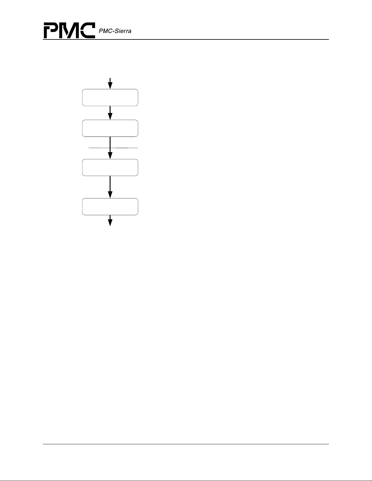
Figure 4: Module Management Flow Diagram
Software State Description
temuxModuleOpen
temuxModuleSt art
temuxModuleSt op
temuxModuleCl ose
START
END
Perfor ms modul e level ini tial ization of the TEMUX driver. Vali dates the
Module Ini tial ization Vector (MIV). All ocates memory for t he MDB and all
it s component s (i .e. al l the memory needed by the dri ver) and then
ini tiali zes the content s of the MDB with t he validat ed MI V.
Perfor ms modul e level startup of the driver. This i nvolves al locati ng RTOS
resources such as semaphores and ti mer s.
Perfor m all device l evel functi ons here (add, ini t, activate,
de-act ivate, reset , del ete)
Perfor ms Modul e level shutdown of t he TEMUX driver. Thi s involves
delet ing all devi ces current ly inst alled and de-allocati ng all t imers and
semaphores as well as removing the ISR handler and DPR task.
Perfor ms modul e level shutdown of the dri ver. Delet es all devices currentl y
regi stered wit h the dr iver and de-all ocates all t he dri ver's memory.
Device Management
The following figure shows the functions and process that the driver uses to add, initialize, reinitialize, or delete devices.
Proprietary and Confidential to PMC-Sierra, Inc., and for its Customers’ Internal Use 21
Document ID: PMC-1991611, Issue 2
Page 22
TEMUX/TEMAP/TECT3 (PM8315, PM5365, PM4328) Driver Manual
A
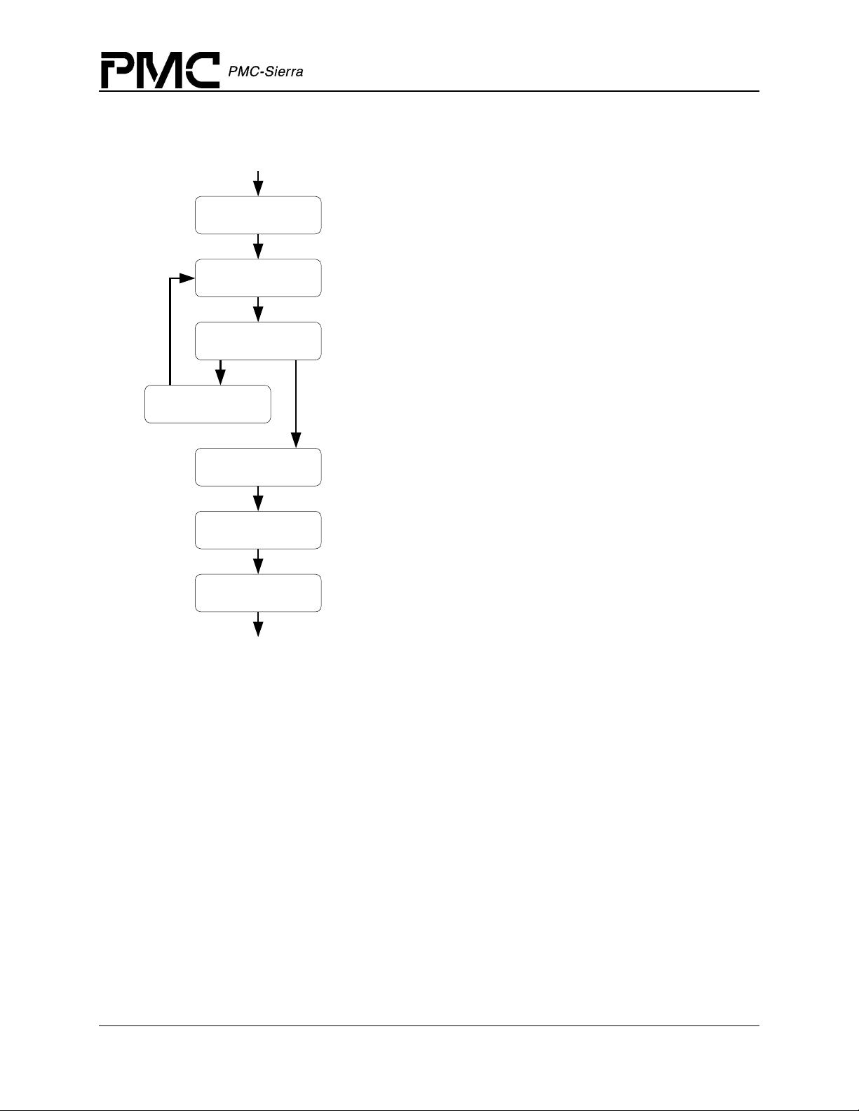
Figure 5: Device Management Flow Diagram
Software State Description
temuxActivate
temuxReset
temuxDeactivate
temuxReset
START
temuxAdd
temuxInit
performs a register readback test,
allocates memory for storing device context
information, and applies a software reset to the device (using
temuxReset).
Initializes the device based on an initialization vector provided by the
application. The initialization vector is validated by the application and
stored by the driver as part of device context information. The device
registers are then configured accordingly.
Prepares the device for normal operation by enabling interrupts and other
global enables. The device is now operational and all other APIs
can be invoked.
Deactivates the device; and resets the device’s context, which enables the
application to once again initialize the device.
De-activates the device and removes it from normal operation. This
involves disabling the device interrupts and other global enables, such as
links.
pplies a software reset to the device to put it in its default startup state.
Removes the device from the list of devices being controlled by the
temuxDelete
END
TEMUX driver. This function clears the device context information
for the device being deleted.
3.4 Interrupt Servicing
The TEMUX/TEMAP/TECT3 driver services device interrupts using an Interrupt-Service
Routine (ISR) that traps interrupts and a deferred interrupt-processing routine (DPR) that actually
processes the interrupt conditions. This lets the ISR execute quickly and exit. Most of the
time-consuming processing of the interrupt conditions is deferred to the DPR by queuing the
necessary interrupt-context information to the DPR task. The DPR function runs in the context of
a separate task within the RTOS.
Note: Since the DPR task processes potentially serious interrupt conditions, you should set the
DPR task’s priority higher than the application task interacting with the
TEMUX/TEMAP/TECT3 driver.
Proprietary and Confidential to PMC-Sierra, Inc., and for its Customers’ Internal Use 22
Document ID: PMC-1991611, Issue 2
Page 23
TEMUX/TEMAP/TECT3 (PM8315, PM5365, PM4328) Driver Manual
Software State Description
The driver provides system-independent functions, temuxISR and temuxDPR. You must fill in
the corresponding system-specific functions,
sysTemuxISRHandler and sysTemuxDPRTask.
The system-specific functions isolate the system-specific communication mechanism (between
the ISR and DPR) from the system-independent functions,
temuxISR and temuxDPR.
Figure 6 illustrates the interrupt service model used in the TEMUX/TEMAP/TECT3 driver
design.
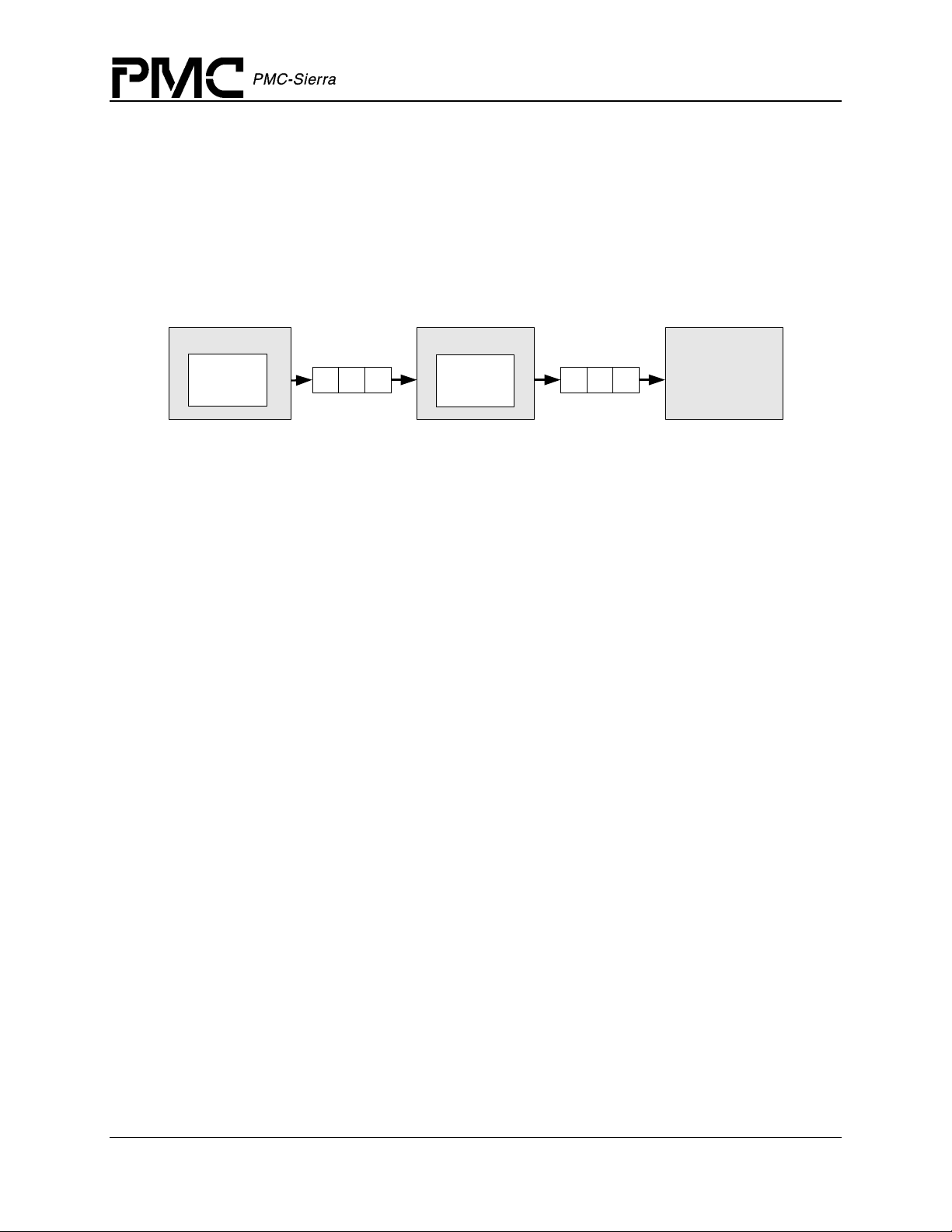
Figure 6: Interrupt Service Model
sysTemuxISRHandler
temuxISR
Interrupt
Status
sysTemuxDPRTask
temuxDPR
Indication
Callbacks
Application
Note: Instead of using an interrupt service model, you can use a polling service model in the
TEMUX/TEMAP/TECT3 driver to process the device’s event-indication registers.
Calling temuxISR
An interrupt handler function, which is system dependent, must call temuxISR. But first, the
low-level interrupt-handler function must trap the device interrupts. You must implement this
function for your system.
The interrupt handler that you implement (
vector table of the system processor. Then it is called when one or more
TEMUX/TEMAP/TECT3 devices interrupt the processor. The interrupt handler then calls
temuxISR for each device in the active state that requires service.
The
temuxISR function reads from the master interrupt-status registers and the miscellaneous
interrupt-status registers of the TEMUX/TEMAP/TECT3. Then
status information if valid status bits are set. The
turn clears the initial cause of the interrupt. The
message to the DPR task (for each device that requested service) which contains the valid
interrupt status bits and the device’s context handle.
sysTemuxISRHandler) is installed in the interrupt
temuxISR returns with this
temuxISR also clears those status bits, which in
sysTemuxISRHandler function then sends a
Note: Normally you should pass the status information for deferred interrupt processing by
implementing a message queue.
Calling temuxDPR
The sysTemuxDPRTask function is a system specific function that runs as a separate task within
the RTOS. You should set the DPR task’s priority higher than the application task(s) interacting
with the TEMUX/TEMAP/TECT3 driver. In the message-queue implementation model, this task
has an associated message queue. The task waits for messages from the ISR on this message
queue. When a message arrives,
Proprietary and Confidential to PMC-Sierra, Inc., and for its Customers’ Internal Use 23
Document ID: PMC-1991611, Issue 2
sysTemuxDPRTask calls the DPR (temuxDPR).
Page 24

TEMUX/TEMAP/TECT3 (PM8315, PM5365, PM4328) Driver Manual
Software State Description
Then temuxDPR processes the status information and takes appropriate action based on the
specific interrupt condition detected. The nature of this processing can differ from system to
system. Therefore,
temuxDPR calls different indication callbacks for different interrupt
conditions.
Typically, you should implement these callback functions as simple message posting functions
that post messages to an application task. However, you can implement the indication callback to
perform processing within the DPR task context and return without sending any messages. In this
case, ensure that the indication function does not call any API functions that change the driver’s
state, such as
temuxDelete. Also, ensure that the indication function is non-blocking. You can
customize these callbacks to suit your system.
Note: Since the
temuxISR and temuxDPR routines themselves do not specify a communication
mechanism, you have full flexibility in choosing a communication mechanism between the two.
A convenient way to implement this communication mechanism is to use a message queue, which
is a service that most RTOSs provide.
You must implement the two system specific functions,
sysTemuxDPRTask. When the driver calls sysTemuxISRHandlerInstall for the first time,
the driver installs
sysTemuxDPRTask function is spawned as a task when sysTemuxDPRTaskInstall is called.
sysTemuxISRHandlerInstall function also creates the communication channel between
The
sysTemuxISRHandler and sysTemuxDPRTask. This communication channel is most
sysTemuxISRHandler in the interrupt vector table of the processor. The
commonly a message queue associated with the
Similarly, during removal of interrupts, the driver removes
microprocessor’s interrupt vector table when
As a reference, this manual provides example implementations of the interrupt installation and
removal functions on page 81. You can customize these prototypes to suit your specific needs.
3.5 Polling Servicing
sysTemuxISRHandler and
sysTemuxDPRTask.
sysTemuxISRHandler from the
sysTemuxDPRTaskRemove is called.
Instead of using an interrupt service model, you can use a polling service model in the
TEMUX/TEMAP/TECT3 driver to process the device’s event-indication registers.
Figure 7 illustrates the polling service model used in the TEMUX/TEMAP/TECT3 driver design.
Figure 7: Polling Service Model
Indication
Callbacks
temuxDPR
Application
Proprietary and Confidential to PMC-Sierra, Inc., and for its Customers’ Internal Use 24
Document ID: PMC-1991611, Issue 2
Page 25

TEMUX/TEMAP/TECT3 (PM8315, PM5365, PM4328) Driver Manual
Software State Description
The polling service code includes some system specific code (prefixed by “sysTemux”), which
typically you must implement for your application. The polling service code also includes some
system independent code (prefixed by “
temux”) provided by the driver that does not change from
system to system.
In polling mode,
sysTemuxISRHandler and temuxISR are not used. When temuxPoll is
called, the message normally sent to the DPR is now passed internally.
The nature of this processing can differ from system to system. Therefore, the DPR calls different
indication callbacks for different interrupt conditions. You can customize these callbacks to fit
your application’s specific requirements. See page 75 for a description of these callback
functions.
Proprietary and Confidential to PMC-Sierra, Inc., and for its Customers’ Internal Use 25
Document ID: PMC-1991611, Issue 2
Page 26

TEMUX/TEMAP/TECT3 (PM8315, PM5365, PM4328) Driver Manual
4 DATA STRUCTURES
4.1 Constants
The file temux.h defines the lowest level (compile time) items, generally those that are needed
by any application code in order to interface with the driver. All source and header files include
this file. The compile constants are defined in the file
etc.
Data Structures
temux.h as UINT1, UINT2, UINT4,
The file
tmx_api.h defines the set of (run time) items needed to interface directly with the core
API functions. The following constants are defined in the file
·
TMX_MAX_DEVICES: defines the maximum number of devices that can be supported by this
driver. This constant must not be changed without a thorough analysis of the consequences to
the driver code
· <
TEMUX ERROR CODES>: error codes used throughout the driver code, returned by the API
functions and (when
TMX_FAIL is returned to a function’s caller) used in the global error
number field of the MDB or DDB
·
sTMX_MIV: structure passed by the application into the temuxModuleOpen function call.
·
sTMX_DIV: structure passed by the application into the temuxAdd function call.
The remaining files should only be needed for extended interfaces that make use of the internal
structures or functions of the driver.
4.2 Data Structures
The following are the main data structures employed by the TEMUX/TEMAP/TECT3 driver.
tmx_api.h.
4.3 Structures Passed by the Application
These structures are defined for use by the application and are passed by reference to functions
within the driver.
Module Initialization Vector
Passed via the temuxModuleOpen call, this structure contains all the information needed by the
driver to initialize the module. Special or unusual fields are described first:
·
pMDB: can be used by the application to pass the address of a pre-allocated MDB. If pMDB is
NULL, the driver will allocate sufficient memory to hold the MDB and return its address in
pMDB field.
the
Proprietary and Confidential to PMC-Sierra, Inc., and for its Customers’ Internal Use 26
Document ID: PMC-1991611, Issue 2
Page 27
TEMUX/TEMAP/TECT3 (PM8315, PM5365, PM4328) Driver Manual
Data Structures
· maxDevs: is used to inform the driver how many devices will be operating concurrently
during this session. The number is used to calculate the amount of memory that will be
allocated to the driver. The maximum value that can be passed is
TMX_MAX_DEVICES.
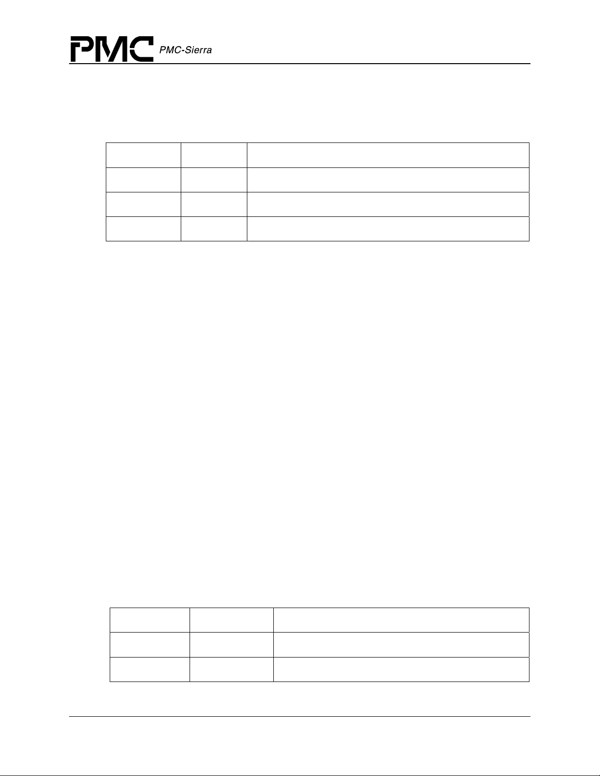
Table 3: Module Initialization Vector: sTMX_MIV
Field Name Field Type Field Description
autoStart UINT2
pMDB void *
maxDevs UINT2
indicates to driver to start the module when opened
(pointer to) pre-allocated or (if NULL) returned MDB
number of devices that must be supported for this session
Device Initialization Vector
Passed via the temuxAdd call, this structure contains all the information needed by the driver to
initialize a TEMUX/TEMAP/TECT3 device. Special or unusual fields are described first:
·
pDDB can be used by the application to pass the address of a pre-allocated DDB. If pDDB is
NULL, the driver will allocate sufficient memory to hold the DDB and return its address in
the
pDDB field.
·
baseAddress: must contain the hardware base address of the device.
·
usrCtxt: this field is strictly a user field. The value passed into the function via this element
will be stored in the DDB and passed back to the application during DPR processing. The
user might use it to identify ‘this’ device or point to some data related to this device.
·
autoInit: is a flag that tells the driver to automatically initialize the device being added
(calling
the device left uninitialized, and the application will have to call temuxInit at a later time.
temuxInit internally does this). If the flag is zero, the DDB will be initialized and
profileNum: is used only when autoInit is set and indicates which mode the device should
·
be initialized into. The function of this element is the same as the profileNum argument to the
function temuxInit. A value of zero indicates that during initialization, after the device is
reset, all registers should remain unchanged (in their initial state).
cbackIO, cbackDS3, cbackFramer, cbackMapper: Passes the addresses of
·
application functions used by the DPR to inform the application code of pending events. If
the user sets the element to NULL, then any events that might cause the DPR to ‘call back’ to
the application will be processed during ISR processing but ignored by the DPR.
Table 4: Device Initialization Vector: sTMX_DIV
Field Name Field Type Field Description
pDDB void *
baseAddress UINT1 *
Proprietary and Confidential to PMC-Sierra, Inc., and for its Customers’ Internal Use 27
Document ID: PMC-1991611, Issue 2
(pointer to) pre-allocated or (if NULL) returned DDB
device base address
Page 28
TEMUX/TEMAP/TECT3 (PM8315, PM5365, PM4328) Driver Manual
Field Name Field Type Field Description
Data Structures
usrCtxt void *
a user-supplied value that is returned in callback
functions
autoInit UINT2
profileNum UINT2
if non-zero, temuxInit is called internally
profile number to be used for initialization. A profile
number of zero indicates that the driver should leave all
the device registers unchanged after reset
modeISR TMX_ISR_MODE
cbackIO void *
cbackDS3 void *
cbackFramer void *
cbackMapper void *
indicates the type of ISR/polling to do
address of the callback function for IO Events
address of the callback function for DS3 Events
address of the callback function for Framer Events
address of the callback function for Mapper Events (not
valid in TECT3)
Device Initialization Profile
The device initialization profile is used to initialize the TEMUX/TEMAP/TECT3 device to a
specific operating mode. It is used by the profile manipulation functions
temuxGetInitProfile, etc.) and temuxInit. Important fields are given below.
(
Table 5: Device Initialization Profile: sTMX_INIT_PROF
Field Name Field Type Field Description
lineopt UINT2
sysopt UINT2
opmode UINT2
e1Mode BOOLEAN
autoActivate BOOLEAN
lineopt can be one of the following:
TMX_LINEOPT_LIU_DS3 : DS3 Mux with serial LIU interface
·
·
TMX_LINEOPT_SDH_DS3: DS3 Mux with DS3 SONET/SDH Mapper (Not valid in TECT3)
TMX_LINEOPT_SDH_E1T1: E1/T1 Mapper
·
sysopt can be one of the following:
Proprietary and Confidential to PMC-Sierra, Inc., and for its Customers’ Internal Use 28
Document ID: PMC-1991611, Issue 2
Line side configuration options
System side configuration options
Operation mode
Set device to E1 mode
Activates the device for operation
Page 29

TEMUX/TEMAP/TECT3 (PM8315, PM5365, PM4328) Driver Manual
Data Structures
· TMX_SYSOPT_CDATA: Serial Clock/Data Interface
·
TMX_SYSOPT_MVIP: H-MVIP interface (not valid in TEMAP)
·
TMX_SYSOPT_SBI: SBI Interface
TMX_SYSOPT_SBI_CCS: SBI with CAS or CCS H-MVIP (not valid in TEMAP)
·
·
TMX_SYSOPT_CDATA_CCS: Serial Clock/Data with CCS H-MVIP (not valid in TEMAP)
opmode can be one of the following:
·
TMX_OPMODE_FRAMER: High Density Framer Mode (not valid in TEMAP)
·
TMX_OPMODE_MAPPER: Mapper/Multiplexor Mode (not valid in TECT3)
·
TMX_OPMODE_TRANSMUX: TransMux mode (not valid in TECT3)
·
TMX_OPMODE_DS3_ONLY: DS3 Framer Only
Preset Profiles
There are 8 preset profiles (indexed 0-7) that can be used to initialize the device during the call to
temuxInit. They are set to the values shown in Table 6.
Table 6: Preset Profiles: temuxInit
Profile
lineopt sysopt opmode e1Mode
Number
0 TMX_LINEOPT_LIU_
DS3
1 TMX_LINEOPT_SDH_
E1T1
2 TMX_LINEOPT_SDH_
E1T1
3 TMX_LINEOPT_SDH_
E1T1
4 TMX_LINEOPT_LIU_
DS3
5 TMX_LINEOPT_LIU_
DS3
6 TMX_LINEOPT_LIU_
DS3
TMX_SYSOPT_
SBI
TMX_SYSOPT_
CDATA
TMX_SYSOPT_
MVIP
TMX_SYSOPT_
SBI
TMX_SYSOPT_
CDATA
TMX_SYSOPT_
CDATA
TMX_SYSOPT_
CDATA
TMX_OPMODE_FRAMER FALSE
TMX_OPMODE_FRAMER TRUE
TMX_OPMODE_FRAMER FALSE
TMX_OPMODE_FRAMER FALSE
TMX_OPMODE_FRAMER FALSE
TMX_OPMODE_MAPPER FALSE
TMX_OPMODE_DS3_ONLY FALSE
7 TMX_LINEOPT_LIU_
DS3
Proprietary and Confidential to PMC-Sierra, Inc., and for its Customers’ Internal Use 29
Document ID: PMC-1991611, Issue 2
TMX_SYSOPT_
CDATA
TMX_OPMODE_TRANSMUX FALSE
Page 30
TEMUX/TEMAP/TECT3 (PM8315, PM5365, PM4328) Driver Manual
Data Structures
Profiles 0-4 are not valid with the TEMAP device. Profiles 1-3, 5, 7 are not valid in the TECT3
device.
Interrupt-Service Routine Mask Vector
Passed via the temuxClearMask, temuxGetMask and the temuxSetMask calls, this structure
contains all the information needed by the driver to enable and disable any of the interrupts in the
TEMUX/TEMAP/TECT3.
Table 7: ISR Mask Vector: sTMX_MASK
Field Name Field Type Sets / Clears Interrupt Condition
sdet0e UINT1
sdet1e UINT1
io struct tmx_mask_io
ds3 struct tmx_mask_ds3
mux[7] struct tmx_mask_mux
framer[28] struct tmx_mask_framer
mapper struct tmx_mask_mapper
SBI collision detect (register 0)
SBI collision detect (register 1)
IO Section interrupts
DS3 Section interrupts
MUX/MX12/DS2 Section interrupts
FRAMER Section interrupts
MAPPER Section interrupts (not valid in
TECT3)
Mask Sub-structures
These structures also appear in sTMX_MASK (above).
Table 8: IO Section Masks: struct tmx_mask_io
Field Name Field Type Field Description
exsbi.ovre UINT1
exsbi.unde UINT1
insbi.ovre UINT1
insbi.unde UINT1
exsbi.pare UINT1
Proprietary and Confidential to PMC-Sierra, Inc., and for its Customers’ Internal Use 30
Document ID: PMC-1991611, Issue 2
SBI bus egress overrun
SBI bus egress underrun
SBI bus ingress overrun
SBI bus ingress underrun
SBI bus parity
Page 31

TEMUX/TEMAP/TECT3 (PM8315, PM5365, PM4328) Driver Manual
Table 9: DS3 Section Masks: struct tmx_mask_ds3
Field Name Field Type Field Description
Data Structures
pmon.inte UINT1
rdlc.inte UINT1
rboc.idle UINT1
rboc.feace UINT1
frmr.cofae UINT1
frmr.rede UINT1
frmr.cbite UINT1
frmr.ferfe UINT1
frmr.idle UINT1
frmr.aise UINT1
frmr.oofe UINT1
frmr.lose UINT1
DS3 PMON Accumulation Transfer
DS3 Receive DLC State Transition
DS3 Receive BOC FEAC Removed (not valid in
TEMAP)
DS3 Receive BOC FEAC Detected
DS3 Framer Change of Frame Alignment
DS3 Framer RED Alarm Transition
DS3 Framer C-Bit Transition
DS3 Framer Far End Receive Failure Transition
DS3 Framer Idle Signal Transition
DS3 Framer AIS Signal Transition
DS3 Framer Out of Frame Transition
DS3 Framer Loss of Signal Transition
tdpr.fulle UINT1
tdpr.ovre UINT1
tdpr.unde UINT1
tdpr.lfille UINT1
mx23.inte UINT1
prgd.synce UINT1
prgd.bee UINT1
prgd.xfere UINT1
DS3 Transmit DLC Fifo Full
DS3 Transmit DLC Fifo Overrun
DS3 Transmit DLC Fifo Underrun
DS3 Transmit DLC Empty (or Low Water Mark)
MX23 Loopback Request Detected
DS3 PRGD Synchronization Transition
DS3 PRGD Bit Error Detected
DS3 PRGD Accumulation Transfer
Table 10: MUX Section Masks: struct tmx_mask_mux
Field Name Field Type Field Description
ds2.inte.cofae UINT1
DS2 Change of Frame Alignment Detected
Proprietary and Confidential to PMC-Sierra, Inc., and for its Customers’ Internal Use 31
Document ID: PMC-1991611, Issue 2
Page 32

TEMUX/TEMAP/TECT3 (PM8315, PM5365, PM4328) Driver Manual
Field Name Field Type Field Description
Data Structures
ds2.inte.rede UINT1
ds2.inte.ferfe UINT1
ds2.inte.aise UINT1
ds2.inte.oofe UINT1
ds2.intr.inte UINT1
mx12.inte UINT1
DS2 Red Alarm Transition
DS2 Far End Receive Failure Transition
DS2 AIS Signal Transition
DS2 Out of Frame Transition
DS2 Error Counter Transfer
MX12 Loopback Request Detected
Table 11: Framer Section Masks: struct tmx_mask_framer
Field Name Field Type Field Description
rjat.ovre UINT1
rjat.unde UINT1
tjat.ovre UINT1
tjat.unde UINT1
T1/E1 Framer RJAT Overrun
T1/E1 Framer RJAT Underrun
T1/E1 Framer TJAT Overrun
T1/E1 Framer TJAT Underrun
tx_elst.slipe UINT1
sig_elst.slipe UINT1
T1/E1 Framer TX_ELST Slip (not valid in TEMAP)
T1/E1 Framer Signaling ELST Slip (not valid in
TEMAP)
rx_elst.slipe UINT1
sigx.sige UINT1
t1_frmr.cofae UINT1
t1_frmr.fere UINT1
t1_frmr.beee UINT1
t1_frmr.sfee UINT1
t1_frmr.mfpe UINT1
t1_frmr.infre UINT1
e1_frmr.c2nciwe UINT1
T1/E1 Framer RX_ELST Slip (not valid in TEMAP)
Change of signaling state (COS) (not valid in TEMAP)
T1 Framer Change of Frame Alignment Detected
T1 Framer Framing Bit Error Detected
T1 Framer Bit Error Detected
T1 Framer Severely Errored Framing Event Detected
T1 Framer Framing Bit Mimic Detected
T1 Framer is Inframe
E1 Framer CRC to Non-CRC Interworking Mode
Transition
Proprietary and Confidential to PMC-Sierra, Inc., and for its Customers’ Internal Use 32
Document ID: PMC-1991611, Issue 2
Page 33

TEMUX/TEMAP/TECT3 (PM8315, PM5365, PM4328) Driver Manual
Field Name Field Type Field Description
Data Structures
e1_frmr.oofe UINT1
e1_frmr.oosmfe UINT1
e1_frmr.oocmfe UINT1
e1_frmr.cofae UINT1
e1_frmr.fere UINT1
e1_frmr.smfere UINT1
e1_frmr.cmfere UINT1
e1_frmr.raie UINT1
e1_frmr.rmaie UINT1
e1_frmr.aisde UINT1
e1_frmr.rede UINT1
E1 Framer Out of Frame Transition
E1 Framer Out of Signaling Multiframe Transition
E1 Framer Out of CRC Multiframe Transition
E1 Framer Change of Frame Alignment Detected
E1 Framer Framing Bit Error Detected
E1 Framer Signaling Multiframe Framing Bit Error
Detected
E1 Framer CRC Multiframe Framing Bit Error
Detected
E1 Framer Remote Alarm Indication Transition
E1 Framer Remote Multiframe Alarm Indication
Transition
E1 Framer Alarm Indication
E1 Framer Red Alarm Transition
e1_frmr.aise UINT1
e1_frmr.febee UINT1
e1_frmr.crcee UINT1
e1_frmr.sa4e UINT1
e1_frmr.sa5e UINT1
e1_frmr.sa6e UINT1
e1_frmr.sa7e UINT1
e1_frmr.sa8e UINT1
e1_frmr.ooofe UINT1
e1_frmr.raiccrce UINT1
e1_frmr.cfebee UINT1
e1_frmr.v52linke UINT1
E1 Framer AIS
E1 Framer Far End Bit Error Detected
E1 Framer CRC Error Detected
E1 Framer National Use Bit Sa4 Transition
E1 Framer National Use Bit Sa5 Transition
E1 Framer National Use Bit Sa6 Transition
E1 Framer National Use Bit Sa7 Transition
E1 Framer National Use Bit Sa8 Transition
E1 Framer Out of Offline Frame
E1 Framer RAI & CRC Detected
E1 Framer Continuous FEBE Detected
E1 Framer V52 Link Detected
Proprietary and Confidential to PMC-Sierra, Inc., and for its Customers’ Internal Use 33
Document ID: PMC-1991611, Issue 2
Page 34

TEMUX/TEMAP/TECT3 (PM8315, PM5365, PM4328) Driver Manual
Field Name Field Type Field Description
Data Structures
e1_frmr.ifpe UINT1
e1_frmr.icsmfpe UINT1
e1_frmr.icmfpe UINT1
e1_frmr.ismfpe UINT1
e1_tran.sigmfe UINT1
e1_tran.nfase UINT1
e1_tran.mfe UINT1
e1_tran.smfe UINT1
e1_tran.frme UINT1
E1 Framer Input Frame Pulse Asserted
E1 Framer Input CRC Sub-Multiframe Pulse Asserted
E1 Framer Input CRC Multiframe Pulse Asserted
E1 Framer (Rx) Input Signaling Multiframe Pulse
Asserted
E1 Framer (Tx) Signaling Multiframe Boundry
Detected (not valid in TEMAP)
E1 Framer (Tx) NFAS Frame Boundary Detected (not
valid in TEMAP)
E1 Framer (Tx) CRC-4 Multiframe Boundary Detected
(not valid in TEMAP)
E1 Framer (Tx) CRC-4 Sub-Multiframe Boundary
Detected (not valid in TEMAP)
E1 Framer (Tx) Frame Boundary Detected (not valid in
TEMAP)
pmon.inte UINT1
aprm.inte UINT1
E1/T1 Framer PMON Counter Transfer
T1 Framer APRM 1 Second Data Available (not valid
in TEMAP)
prbs.synce UINT1
prbs.bee UINT1
prbs.xfere UINT1
T1 Framer PRBS Synchronization Transition
T1 Framer PRBS Bit Error Detected
T1 Framer PRMS Accumulation Transfer (not valid in
TEMAP)
tdpr.printe UINT1
E1/T1 Framer Performance Report Ready (not valid in
TEMAP)
tdpr.fulle UINT1
tdpr.ovre UINT1
tdpr.unde UINT1
tdpr.lfille UINT1
E1/T1 Framer Fifo Full (not valid in TEMAP)
E1/T1 Framer Fifo Overrun (not valid in TEMAP)
E1/T1 Framer Fifo Underrun (not valid in TEMAP)
E1/T1 Framer Fifo Empty (or Low Water Mark) (not
valid in TEMAP)
Proprietary and Confidential to PMC-Sierra, Inc., and for its Customers’ Internal Use 34
Document ID: PMC-1991611, Issue 2
Page 35

TEMUX/TEMAP/TECT3 (PM8315, PM5365, PM4328) Driver Manual
Field Name Field Type Field Description
Data Structures
rdlc.inte UINT1
almi.yele UINT1
almi.rede UINT1
almi.aise UINT1
rboc.idlee UINT1
E1/T1 Framer Receive DLC (not valid in TEMAP)
E1/T1 Framer ALMI Yellow Alarm Detected
E1/T1 Framer ALMI RED Alarm Detected
E1/T1 Framer ALMI AIS Detected
T1 Framer Receive BOC FEAC Removed (not valid in
TEMAP)
rboc.boce UINT1
T1 Framer Receive BOC FEAC Detected (not valid in
TEMAP)
Table 12: Mapper Section Masks: struct tmx_mask_mapper (not valid in TECT3 device)
Field Name Field Type Field Description
icfg.ldpe UINT1
d3ma.oflie UINT1
d3ma.uflie UINT1
Line Side Drop Parity Error
D3MA elastic store overflow
D3MA elastic store underflow
d3md.oflie UINT1
d3md.uflie UINT1
etpp[TUG2].pee[TU]¹
etpp[TUG2].alarme[TU]¹ UINT1
UINT1
D3MD elastic store overflow
D3MD elastic store underflow
Egress Tributary Payload Processor pointer
event
Egress Tributary Payload Processor loss of
pointer and path AIS
itpp[TUG2].pee[TU]¹ UINT1
Ingress Tributary Payload Processor pointer
event
itpp[TUG2].alarme[TU]¹ UINT1
Ingress Tributary Payload Processor loss of
pointer and path AIS
rtop[TUG2].pslue[TU]¹ UINT1
Receive Tributary Path Overhead Processor
path signal label unstable
rtop[TUG2].pslme[TU]¹ UINT1
Receive Tributary Path Overhead Processor
path signal label mismatch
Proprietary and Confidential to PMC-Sierra, Inc., and for its Customers’ Internal Use 35
Document ID: PMC-1991611, Issue 2
Page 36

TEMUX/TEMAP/TECT3 (PM8315, PM5365, PM4328) Driver Manual
Field Name Field Type Field Description
Data Structures
rtop[TUG2].copsle[TU]¹ UINT1
Receive Tributary Path Overhead Processor
change of path signal label
rtop[TUG2].rfie[TU]¹ UINT1
Receive Tributary Path Overhead Processor
remote failure indication
rtop[TUG2].rdie[TU]¹ UINT1
Receive Tributary Path Overhead Processor
remote defect indication
Note
1. TUG2 refers to a range from 1 to 7 corresponding to TUG2 #1 to TUG2 #7 and TU refers to a
range from 1 to 4 corresponding TU #1 to TU #4
Device Diagnostic Structures
Table 13: PRGD configuration: sTMX_PRGD
Field Name Field Type Field Description
enable BOOLEAN
control UINT1
enable DS3 pseudo random number generator
PRGD control register
ienable UINT1
length UINT1
tap UINT1
error UINT1
pattern UINT4
PRGD interrupt enable register
PRGD length register
PRGD tap register
PRGD error insertion register
PRGD pattern insertion registers #1-4
Table 14: PRBS configuration: sTMX_PRBS
Field Name Field Type Field Description
enable UINT1
control UINT1
ienable UINT1
pattern UINT1
Enable Framer PRBS generation
PRBS generator/checker control register
PRBS checker interrupt enable register
PRBS pattern select register
Proprietary and Confidential to PMC-Sierra, Inc., and for its Customers’ Internal Use 36
Document ID: PMC-1991611, Issue 2
Page 37

TEMUX/TEMAP/TECT3 (PM8315, PM5365, PM4328) Driver Manual
4.4 Structures in the Driver’s Allocated Memory
These structures are defined and used by the driver and are part of the context memory allocated
when the driver is opened.
Module Data Block
The MDB is the top level structure for the module. It contains configuration data about the
module level code and pointers to configuration data about the device level codes. Special or
unusual elements in the MDB are described first, followed by the complete list of elements in
table form.
errModule: most of the module functions return a specific error code directly. When the
·
returned code is
specific error code back to the application. Under those circumstances, the proper error code
is recorded in this element. The element is the first in the structure so that the user can cast
the MDB pointer to a
to include the MDB template into the application code).
modValid: indicates that this structure has been properly initialized and may be read by the
·
user.
TMX_FAIL, that indicates that the top level function was not able to carry the
INT4 pointer and retrieve the local error code (this eliminates the need
Data Structures
modState: contains the current state of the module and could be set to: TMX_MOD_START,
·
TMX_MOD_IDLE,
user[]: space is set aside for the user scratch area. The size of the space is controlled by the
·
constant
TMX_USR_SIZE and cannot be less than one UINT4 element. This element can be
used by the user for any type of storage, but only when the MDB field
or TMX_MOD_READY.
modValid is set.
Table 15: Module Data Block: sTMX_MDB
Field Name Field Type Field Description
errModule INT4
maxDevs UINT2
autoStart BOOLEAN
ModState UINT2
ModValid UINT2
NumDevs UINT2
Global error indicator for module calls
Maximum number of devices supported
Indication that temuxModuleStart will be called internally
Module state (TMX_MOD_START, TMX_MOD_IDLE,
TMX_MOD_READY)
Indication that this structure has been initialized (contains
0xCAFE)
Number of devices currently registered
numProfiles UINT2
semModule void *
Proprietary and Confidential to PMC-Sierra, Inc., and for its Customers’ Internal Use 37
Document ID: PMC-1991611, Issue 2
Number of profiles currently registered
Semaphore object
Page 38

TEMUX/TEMAP/TECT3 (PM8315, PM5365, PM4328) Driver Manual
Field Name Field Type Field Description
Data Structures
bufOK BOOLEAN
isrOK BOOLEAN
appMDB BOOLEAN
user[] UINT4
timerModule void *
modMSB sTMX_MSB
pDDB[] sTMX_DDB
Indicates that the call sysTemuxBufferStart succeeded
Indicates that the ISR is installed
Indication that the MDB was pre-allocated by the application
Extra space for use by the application. The array is sized by
the constant value:
TMX_USR_SIZE
Timer object
Module Status Block
Array of (pointers to) DDBs – maxDevs determines how
many in the array
Module Status Block
The MSB contains dynamic information about the health of the module.
Table 16: Module Status Block: sTMX_MSB
Field Name Field Type Field Description
statModule INT4
valid BOOLEAN
General health of the module
Indication that this structure is valid
Device Data Block
The DDB is the top level structure for each device. It contains configuration data about the device
level code and pointers to configuration data about device level sub-blocks. Special or unusual
elements in the DDB are described first, followed by the complete list of elements in table form.
errDevice: most of the device functions return a specific error code directly. When the
·
returned code is
specific error code back to the application. In addition, some device functions do not return
an error code. Under those circumstances, the proper error code is recorded in this element.
The element is the first in the structure so that the user can cast the DDB pointer to a INT4
pointer and retrieve the local error code (this eliminates the need to include the DDB template
into the application code).
·
usrCtxt: this value can be used by the user to identify this device during the execution of
callback functions. It is passed to the driver in the DIV when
returned to the user in the DPV when a callback function is called. The element is unused by
the driver itself and may contain any value.
TMX_FAIL, that indicates that the top level function was not able to carry the
temuxAdd is called and
Proprietary and Confidential to PMC-Sierra, Inc., and for its Customers’ Internal Use 38
Document ID: PMC-1991611, Issue 2
Page 39

TEMUX/TEMAP/TECT3 (PM8315, PM5365, PM4328) Driver Manual
Data Structures
· DevState: contains the current state of the device and could be set to: TMX_START,
TMX_PRESENT, TMX_ACTIVE
devValid: indicates that this structure has been properly initialized and may be read by the
·
, or TMX_INACTIVE.
user.
·
user[]: space is set aside for the user scratch area. The size of the space is controlled by the
constant
TMX_USR_SIZE and cannot be less than one UINT4 element. This element can be
used by the user for any type of storage while the MDB is ‘valid’, even if the DDB is not
‘valid’.
Table 17: Device Data Block: sTMX_DDB
Field Name Field Type Field Description
errDevice INT4
baseAddress UINT1 *
usrCtxt void *
Global error indicator for device calls
Device base address
Information provided by the user and returned in
callback functions
autoInit BOOLEAN
Indication that the driver will invoke temuxInit
internally
profileNum UINT2
modeISR TMX_ISR_MODE
cbackIO void *
cbackDS3 void *
cbackFramer void *
cbackMapper void *
Current profile (mode) that is in use
Indication of the ISR mode
Address of the callback function for IO Events
Address of the callback function for DS3 Events
Address of the callback function for Framer Events
Address of the callback function for Mapper Events.
(not valid in TECT3)
DevState UINT2
devValid UINT2
isTemap BOOLEAN
isTect3 BOOLEAN
index UINT2
revision UINT2
Proprietary and Confidential to PMC-Sierra, Inc., and for its Customers’ Internal Use 39
Document ID: PMC-1991611, Issue 2
Device state (TMX_START, TMX_PRESENT,
TMX_ACTIVE, TMX_INACTIVE
)
Indication that this structure has been initialized
(contains
0xBEEF)
Indicates if device is TEMAP
Indicates if device is TECT3
Index of this DDB in the table of DDBs
Device type and version (from device registers)
Page 40

TEMUX/TEMAP/TECT3 (PM8315, PM5365, PM4328) Driver Manual
Field Name Field Type Field Description
Data Structures
hwFail BOOLEAN
maskSaved BOOLEAN
Indicates if device cannot be found
Indicates if the current isr mask has been saved into
the member
user[] UINT4
Extra space for use by the application. The array is
sized by the constant value:
devIPV sTMX_IPV
devMASK sTMX_MASK
savedMask sTMX_MASK
devDSB sTMX_DSB
Initialization profile
Interrupt mask
Saved copy of the interrupt mask
Device Status Block
Device Status Block
DSB Top-level Structure
Table 18: Device Status Block: sTMX_DSB
savedMask
TMX_USR_SIZE
Field Name Field Type Field Description
statDevice INT4
A flag derived from periodic checks that
verify that the device is OK
sbi_monitor UINT1
clock_1_monitor UINT1
clock_2_monitor UINT1
clock_3_monitor UINT1
clock_4_monitor UINT1
clock_5_monitor UINT1
io struct tmx_dsb_io
SBI clock monitor register
Master clock monitor #1
Master clock monitor #2
Master clock monitor #3
Master clock monitor #4
Master clock monitor #5
Alarms, status and counters from the IO
section(s)
ds3 struct tmx_dsb_ds3
Alarms, status and counters from the
DS3 section(s)
mux[7] struct tmx_dsb_mux
Alarms, status and counters from the
MUX/MX12/DS2 section(s)
Proprietary and Confidential to PMC-Sierra, Inc., and for its Customers’ Internal Use 40
Document ID: PMC-1991611, Issue 2
Page 41

TEMUX/TEMAP/TECT3 (PM8315, PM5365, PM4328) Driver Manual
Field Name Field Type Field Description
Data Structures
framer[28] struct tmx_dsb_framer
Alarms, status and counters from the
FRAMER section(s)
mapper struct tmx_dsb_mapper
Alarms, status and counters from the
MAPPER section(s) (not valid in
TECT3)
valid BOOLEAN
Indication that this structure is valid
DSB Sub-structures
These structures also appear in the DSB (above).
Table 19: IO Section Status Block: struct tmx_dsb_io
Field Name Field Type Field Description
sbidet0 UINT2
sbidet1 UINT2
SBI bus collision detect count
SBI bus collision detect count
Table 20: DS3 Section Status Block: struct tmx_dsb_ds3
Field Name Field Type Field Description
frmr.stat UINT1
pmon.stat UINT1
pmon.lcv UINT2
pmon.ferr UINT2
pmon.exzs UINT2
pmon.perr UINT2
pmom.cper UINT2
pmon.febe UINT2
rdlc.stat UINT1
DS3 framer status (and alarms)
DS3 framer PMON status
Line code violation event count
F-bit / M-bit error event count
Excess zeros error event count
Parity error event count
Path parity error event count
FEBE event count
DS3 framer PMON status
Proprietary and Confidential to PMC-Sierra, Inc., and for its Customers’ Internal Use 41
Document ID: PMC-1991611, Issue 2
Page 42

TEMUX/TEMAP/TECT3 (PM8315, PM5365, PM4328) Driver Manual
Field Name Field Type Field Description
Data Structures
prgd.pdr UINT4
Pattern detector error count
Table 21: MUX Section Status Block: struct tmx_dsb_mux
Field Name Field Type Field Description
frmr.stat UINT1
frmr.ferr UINT1
DS2 framer status
DS2 framing bit-error event count
Table 22: Framer Section Status Block: struct tmx_dsb_framer
Field Name Field Type Field Description
pmon.fer UINT1
pmon.oof UINT2
FAS / Fe-bit / framing bit error event count
OOF / COFA / far end block error event count
pmon.bee UINT2
prbs.ecnt UINT4
e1.stat UINT1
e1.alarm UINT1
e1.crc UINT2
CRC / bit error count
PRBS error count
E1 framer status
E1 framer alarm bits
E1 framer crc error count
Table 23: Mapper Section Status Block: struct tmx_dsb_mapper (Not valid in TECT3)
Field Name Field Type Field Description
telecom UINT1
SONET/SDH Telecom Bus Signal Monitor
Accumulation Trigger register contents
Proprietary and Confidential to PMC-Sierra, Inc., and for its Customers’ Internal Use 42
Document ID: PMC-1991611, Issue 2
Page 43

4.5 Global Variables
Although most of the variables and structure elements within the driver are supposed to be hidden
from the application code, there are several that provide information that might come in handy for
debugging. They are to be considered read-only by the application.
temuxMDB: A global pointer to the Module Data Block (MDB). The address of the MDB is
·
also returned to the application via the MIV (passed with the
call), in order make available the error code field. The user is cautioned that the MDB is only
valid if the ‘
errModule: this structure element is used to store an error code that specifies the reason
°
for a module API function’s failure. The field is only valid when the function in question
returns a
modValid: a flag that indicates when the MDB has been properly initialized and can be
°
read by the user.
°
modState: this element stores the state of the module (see Figure 3: State Diagram).
·
temuxDDB[]: An array of pointers to the individual Device Data Blocks. The address of each
DDB is also returned to the application via the DIV (passed with the
call), in order to make available the error code field. The user is cautioned that a DDB is only
valid if the ‘
modValid’ flag is set.
TMX_FAIL value.
devValid’ flag is set and that the array of DDBs is in no particular order.
TEMUX/TEMAP/TECT3 (PM8315, PM5365, PM4328) Driver Manual
Data Structures
temuxModuleOpen function
temuxAdd function
°
errDevice: this structure element is used to store an error code that specifies the reason
for a device API function’s failure. The field is only valid when the function in question
returns a
devValid: a flag that indicates when the DDB has been properly initialized and can be
°
TMX_FAIL value.
read by the user.
devState: this element stores the state of the device (see Figure 3: State Diagram).
°
4.6 Structures Passed through RTOS Buffers
Interrupt Status Vector
This block captures the state of the device (during a POLL or during ISR processing) for use by
the Deferred-Processing Routine (DPR). It is the template for all device registers that are
involved in exception processing. It is the application’s responsibility to create a pool of ISV
buffers (using this template to determine the buffer’s size) when the driver calls the user-supplied
sysTemuxBufferStart function call. An individual ISV buffer is then obtained by the driver
via the
sysTemuxISVBufferRtn macro.
Table 24: ISR Status Vector: sTMX_ISV
sysTemuxISVBufferGet macro and returned to the ‘pool’ via the
Field Name Field Type Field Description
devId sTMX_HNDL
Proprietary and Confidential to PMC-Sierra, Inc., and for its Customers’ Internal Use 43
Document ID: PMC-1991611, Issue 2
Device handle
Page 44

TEMUX/TEMAP/TECT3 (PM8315, PM5365, PM4328) Driver Manual
Field Name Field Type Field Description
Data Structures
usrCtxt void *
master UINT1
intsSDH UINT1
intsSBI UINT1
intsDS3 UINT1
intsDS2 UINT1
intsMX12 UINT1
channels UINT4
sbiDet0 UINT2
sbiDet1 UINT2
The user context
Copy of the master ISR register
SDH master interrupt source (not valid in
TECT3)
SBI master interrupt source
DS3 master interrupt source
DS2 master interrupt source
MX12 master interrupt source
Bitmask indicating which T1/E1 framer (of
the 28) slice has generated an interrupt
Master SBIDET0 collision detect interrupt
source
Master SBIDET1 collision detect interrupt
source
io struct tmx_isv_io
ds3 struct tmx_isv_ds3
mux[7] struct tmx_isv_mux
framer[28] struct tmx_isv_framer
mapper struct tmx_isv_mapper
IO Section interrupts
DS3 Section interrupts
MUX/MX12/DS2 Section interrupts
FRAMER Section interrupts
MAPPER Section interrupts (not valid in
TECT3)
ISV Sub-structures
These structures also appear in the ISV (above).
Table 25: IO Section ISR Status Vector: struct tmx_isv_io
Field Name Field Type Field Description
exsbi.und UINT1
SBI bus egress underrun interrupt bits
Proprietary and Confidential to PMC-Sierra, Inc., and for its Customers’ Internal Use 44
Document ID: PMC-1991611, Issue 2
Page 45

TEMUX/TEMAP/TECT3 (PM8315, PM5365, PM4328) Driver Manual
Field Name Field Type Field Description
Data Structures
exsbi.ovr UINT1
exsbi.ints UINT1
insbi.und UINT1
insbi.ovr UINT1
SBI bus egress overrun interrupt bits
SBI bus parity error interrupt bits
SBI bus ingress underrun interrupt bits
SBI bus ingress overrun interrupt bits
Table 26: DS3 Section ISR Status Vector: struct tmx_isv_ds3
Field Name Field Type Field Description
pmon.ints UINT1
rdlc.ints UINT1
rboc.ints UINT1
frmr.ints UINT1
tdpr.ints UINT1
DS3 PMON interrupt bits
DS3 RDLC interrupt bits
DS3 RBOC interrupt bits
DS3 FRMR interrupt bits
DS3 TDPR interrupt bits
mx23.ints UINT1
prgd.intr UINT1
DS3 MX23 interrupt bits
DS3 PRGD interrupt bits
Table 27: MUX Section ISR Status Vector: struct tmx_isv_mux
Field Name Field Type Field Description
ds2.ints UINT1
ds2.intr UINT1
mx12.ints UINT1
DS2 per-channel interrupt bits
DS2 per-channel interrupt bits (additional)
MX12 per-channel interrupt bits
Table 28: Framer Section ISR Status Vector: struct tmx_isv_framer
Field Name Field Type Field Description
frInts1 UINT1
E1/T1 Interrupt Source #1 interrupt bits
Proprietary and Confidential to PMC-Sierra, Inc., and for its Customers’ Internal Use 45
Document ID: PMC-1991611, Issue 2
Page 46

TEMUX/TEMAP/TECT3 (PM8315, PM5365, PM4328) Driver Manual
Field Name Field Type Field Description
Data Structures
frInts2 UINT1
rjat.ints UINT1
tjat.ints UINT1
tx_elst.intr UINT1
sig_elst.intr UINT1
rx_elst.intr UINT1
sigx.coss UINT1
t1_frmr.ints UINT1
e1_frmr.sints UINT1
e1_frmr.mints UINT1
E1/T1 Interrupt Source #2 interrupt bits
E1/T1 receive jitter attenuator interrupt bits
E1/T1 transmit jitter attenuator interrupt bits
E1/T1 transmit elastic store interrupt bits (not valid
in TEMAP)
E1/T1 receive signaling elastic store interrupt bits
(not valid in TEMAP)
E1/T1 receive elastic store interrupt bits (not valid
in TEMAP)
E1/T1 Signaling Extractor interrupt bits (not valid in
TEMAP)
T1 framer interrupt bits
E1 framer status interrupt bits
E1 framer maintenance interrupt bits
e1_frmr.nints UINT1
e1_frmr.lints UINT1
e1_tran.ints UINT1
pmon.intr UINT1
aprm.ints UINT1
rdlc.stat UINT1
prbs.intr UINT1
tdpr.ints UINT1
almi.ints UINT1
rboc.ints UINT1
E1 framer National Codeword interrupt bits
E1 framer V52 Link interrupt bits
E1 transmit interrupts (not valid in TEMAP)
T1 performance monitor interrupt bits
T1 APRM interrupt bits (not valid in TEMAP)
E1/T1 receive HDLC interrupt bits (not valid in
TEMAP)
E1/T1 pattern generator interrupt bits
E1/T1 transmit HDLC interrupt bits (not valid in
TEMAP)
E1/T1 alarm integrator interrupt bits
T1 receive bit oriented code interrupts (not valid in
TEMAP)
Proprietary and Confidential to PMC-Sierra, Inc., and for its Customers’ Internal Use 46
Document ID: PMC-1991611, Issue 2
Page 47

TEMUX/TEMAP/TECT3 (PM8315, PM5365, PM4328) Driver Manual
Table 29: Mapper Section ISR Status Vector: struct tmx_isv_mapper
Field Name Field Type Field Description
Data Structures
etpp[TUG2].ais UINT1
Egress Tributary Payload Processor AIS interrupt
bits
etpp[TUG2].lop UINT1
Egress Tributary Payload Processor LOP
interrupt bits
etpp[TUG2].stat[TU]¹ UINT1
Egress Tributary Payload Processor alarm status
interrupt bits
itpp[TUG2].ais UINT1
Ingress Tributary Payload Processor AIS
interrupt bits
itpp[TUG2].lop UINT1
Ingress Tributary Payload Processor LOP
interrupt bits
itpp[TUG2].stat[TU]¹ UINT1
Ingress Tributary Payload Processor alarm status
interrupt bits
rtop[TUG2].copsl UINT1
Receive Tributary Path Overhead Processor
Change of Path Signal Label interrupt bits
rtop[TUG2].pslm UINT1
Receive Tributary Path Overhead Processor Path
Signal Label Mismatch interrupt bits
rtop[TUG2].pslu UINT1
Receive Tributary Path Overhead Processor Path
Signal Label Unstable interrupt bits
rtop[TUG2].rdi UINT1
Receive Tributary Path Overhead Processor
Remote Defect Indication interrupt bits
rtop[TUG2].rfi UINT1
Receive Tributary Path Overhead Processor
Remote Failure Indication interrupt bits
d3md.ints UINT1
d3ma.ints UINT1
Note
1. TUG2 refers to a range from 1 to 7 corresponding to TUG2 #1 to TUG2 #7 and TU refers to a
range from 1 to 4 corresponding TU #1 to TU #4
DS3 Drop Side Mapper interrupt bits
DS3 Add Side Mapper interrupt bits
Proprietary and Confidential to PMC-Sierra, Inc., and for its Customers’ Internal Use 47
Document ID: PMC-1991611, Issue 2
Page 48

TEMUX/TEMAP/TECT3 (PM8315, PM5365, PM4328) Driver Manual
Data Structures
Deferred-Processing Routine Vector
The DPV block is the template for data that is assembled by the DPR and sent to the application
code as a parameter in a callback routine. The callback routine itself identifies the Section of the
device that caused the DPR processing. Arguments passed via the callback routine identify the
source device (via the
events, that is all the information that the user needs. For others, additional information is needed.
The size of the DPV is kept under sixteen (16) bytes to accommodate the simpler message
passing schemes used by some Operating Systems. The DPV structure definition shown below
defines the format for sTMX_DPV_IO, sTMX_DPV_DS3, sTMX_DPV_FRAMER, and
sTMX_DPV_MAPPER.
Note: The application code is responsible for returning this buffer to the RTOS buffer pool.
Table 30: Deferred-Processing Vector: sTMX_DPV
Field Name Field Type Field Description
usrContext) and the event that triggered the processing. For some
channels UINT4
data UINT4
Framer# or mx# of channel that triggered the event (if needed)
Pointer to HDLC receive data or transmit buffers
Proprietary and Confidential to PMC-Sierra, Inc., and for its Customers’ Internal Use 48
Document ID: PMC-1991611, Issue 2
Page 49

TEMUX/TEMAP/TECT3 (PM8315, PM5365, PM4328) Driver Manual
Application Programming Interface
5 APPLICATION PROGRAMMING INTERFACE
This section provides a detailed description of each function that is a member of the
TEMUX/TEMAP/TECT3 driver Application Programming Interface (API).
5.1 Module Initialization
Opening Modules: temuxModuleOpen
This function performs module level initialization of the driver. This involves allocating all of the
memory needed by the driver and initializing the internal structures. It is also possible for the user
to pre-allocate the memory needed by the driver. The user can also set a flag in the MIV that will
cause this function to invoke
temuxModuleStart before returning.
Prototype
Inputs
Outputs
INT4 temuxModuleOpen (sTMX_MIV *pMIV)
pMIV : (pointer to) the MIV
Places the address of the MDB into the MIV passed by the
application
Returns
Valid States
Side Effects
Success =
Failure =
TMX_ERR_ISOPEN
TMX_ERR_ALLOC
MOD_START
changes the STATE of the MODULE to IDLE
TMX_OK
TMX_ERR_ARG
Closing Modules: temuxModuleClose
This function performs module level shutdown of the driver. If the driver is in the READY state,
temuxModuleStop will be called. All RTOS resources will be returned to the RTOS and the
then
MDB de-allocated.
Prototype
Inputs
Outputs
Proprietary and Confidential to PMC-Sierra, Inc., and for its Customers’ Internal Use 49
Document ID: PMC-1991611, Issue 2
INT4 temuxModuleClose (void)
None
None
Page 50

TEMUX/TEMAP/TECT3 (PM8315, PM5365, PM4328) Driver Manual
Application Programming Interface
Returns
Success =
Failure =
TMX_ERR_INVALID
TMX_ERR_STOP
TMX_ERR_NOTIDLE
TMX_OK
TMX_ERR_CLOSED
Valid States
Side Effects
ALL STATES
Changes the STATE of the MODULE to START
5.2 Module Activation
Starting Modules: temuxModuleStart
This function connects the RTOS resources to the driver. This involves allocating semaphores,
initializing buffers and installing the ISRs and the Deferred-Processing Routine (DPR) Task.
Upon successful return from this function, the driver is ready to add active devices.
Prototype
INT4 temuxModuleStart (void)
Inputs
Outputs
Returns
None
None
Success =
Failure =
TMX_ERR_INVALID
TMX_ERR_ISREADY
TMX_ERR_NOTIDLE
TMX_OK
TMX_ERR_CLOSED
Valid States
Side Effects
IDLE
changes the STATE of the MODULE to READY
Stopping Modules: temuxModuleStop
This function disconnects the RTOS resources from the driver. This involves deallocating
semaphores, freeing-up buffers and uninstalling the ISRs and the Deferred-Processing Routine
(DPR) Task. If there are any registered devices,
Prototype
INT4 temuxModuleStop (void)
temuxDelete is called for each.
Proprietary and Confidential to PMC-Sierra, Inc., and for its Customers’ Internal Use 50
Document ID: PMC-1991611, Issue 2
Page 51

TEMUX/TEMAP/TECT3 (PM8315, PM5365, PM4328) Driver Manual
Application Programming Interface
Inputs
Outputs
Returns
None
None
Success =
Failure =
TMX_ERR_INVALID
TMX_ERR_ISIDLE
TMX_ERR_NOTREADY
TMX_OK
TMX_ERR_CLOSED
Valid States
Side Effects
READY
Changes the STATE of the MODULE to IDLE
5.3 Device Initialization
Adding Devices: temuxAdd
This function verifies the presence of a new device in the hardware, configures a Device Data
Block (DDB), stores the contents of the passed Device Initialization Vector (DIV) and passes a
handle back to the application. The handle is used as a parameter to most of the device API
functions. Caution: It is the user’s responsibility to ensure enough space has been allocated for the
MDB and DDBs if the user decides to handle this task (indicated by passing NULL for the
parameter).
pDIV
Prototype
Inputs
Outputs
sTMX_HNDL temuxAdd (sTMX_DIV *pDIV)
pDIV : (pointer to) the DIV
Places the address of the DDB into the DIV passed by the
application. Places any error codes into the MDB.
Returns
Success = Handle that must be used with most other device calls
Failure = NULL with
TMX_ERR_ARG,
temuxMdb->errModule set to either
TMX_ERR_CLOSED,
TMX_ERR_INVALID,
TMX_ERR_NOTREADY,
TMX_ERR_MAXDEVICE,
TMX_ERR_ADD,
TMX_ERR_HNDL,
TMX_ERR_HWFAIL
Valid States
Side Effects
Proprietary and Confidential to PMC-Sierra, Inc., and for its Customers’ Internal Use 51
Document ID: PMC-1991611, Issue 2
START
changes the STATE of the DEVICE to PRESENT
Page 52

TEMUX/TEMAP/TECT3 (PM8315, PM5365, PM4328) Driver Manual
Application Programming Interface
Deleting Devices: temuxDelete
This function removes the specified device from the group of devices being controlled by the
TEMUX/TEMAP/TECT3 driver. Deleting a device involves invalidating the DDB for that
device.
Prototype
Inputs
Outputs
Returns
INT4 temuxDelete (sTMX_HNDL devId)
devId : device handle (from temuxAdd)
None
Success = TMX_OK
Failure = TMX_ERR_CLOSED
TMX_ERR_INVALID
TMX_ERR_NOTREADY
TMX_ERR_DEACTIVATE
TMX_ERR_NOTINACTIVE
TMX_ERR_RESET
TMX_ERR_NOTPRESENT
TMX_ERR_ISSTART
Valid States
Side Effects
ACTIVE, INACTIVE, PRESENT
Changes the STATE of the device to START
Initializing Devices: temuxInit
This function initializes the device from the information stored in both the DDB and in profiles
that are hard coded into the driver. The device is reset before the initialization is carried out.
Prototype
Inputs
INT4 temuxInit (sTMX_HNDL devId, sTMX_DIV
*pDIV, UINT2 profileNum)
devId : device handle (from temuxAdd)
pDIV : pointer to the Device Initialization
Vector
profileNum : identifies the MODE profile to use
Outputs
Proprietary and Confidential to PMC-Sierra, Inc., and for its Customers’ Internal Use 52
Document ID: PMC-1991611, Issue 2
None
Page 53

TEMUX/TEMAP/TECT3 (PM8315, PM5365, PM4328) Driver Manual
Application Programming Interface
Returns
Success =
TMX_OK
Failure = TMX_ERR_HNDL
TMX_ERR_ARG
TMX_ERR_NOTREADY
TMX_ERR_INVALID
TMX_ERR_NOTPRESENT
TMX_ERR_CLOSED
Valid States
Side Effects
PRESENT
Changes the STATE of the DEVICE to INACTIVE
Resetting Devices: temuxReset
This function applies a software reset to the TEMUX/TEMAP/TECT3 device and in doing so
reinitializes the DDB for this device. This function is typically called before reinitializing the
device (via
Prototype
Inputs
temuxInit).
INT4 temuxReset (sTMX_HNDL devId)
devId : device handle (from temuxAdd)
Outputs
Returns
None
Success =
TMX_OK
Failure = TMX_ERR_HNDL
TMX_ERR_CLOSED
TMX_ERR_NOTREADY
TMX_ERR_DEACTIVATE
TMX_ERR_INVALID
TMX_ERR_NOTINACTIVE
Valid States
Side Effects
ACTIVE, INACTIVE
Changes the STATE of the DEVICE to PRESENT
Deactivating Devices: temuxDeActivate
This function deactivates the device from operation. Interrupts are masked and the device is put
into a quiet state via section enable bits.
Prototype
INT4 temuxDeActivate (sTMX_HNDL devId)
Inputs
Proprietary and Confidential to PMC-Sierra, Inc., and for its Customers’ Internal Use 53
Document ID: PMC-1991611, Issue 2
devId : device handle (from temuxAdd)
Page 54

TEMUX/TEMAP/TECT3 (PM8315, PM5365, PM4328) Driver Manual
Application Programming Interface
Outputs
Returns
None
Success = TMX_OK
Failure = TMX_ERR_HNDL
TMX_ERR_INVALID
TMX_ERR_NOTREADY
TMX_ERR_CLOSED
TMX_ERR_NOTACTIVE
Valid States
Side Effects
ACTIVE
Changes the STATE of the DEVICE to INACTIVE
Activating Devices: temuxActivate
This function restores the state of a device after deactivation. Interrupts may be re-enabled.
Prototype
Inputs
INT4 temuxActivate (sTMX_HNDL devId)
devId : device handle (from temuxAdd)
Outputs
Returns
None
Success =
TMX_OK
Failure = TMX_ERR_HNDL
TMX_ERR_CLOSED
TMX_ERR_INVALID
TMX_ERR_NOTREADY
TMX_ERR_NOTINACTIVE
Valid States
Side Effects
INACTIVE
Changes the STATE of the DEVICE to ACTIVE
Add Initialization Profile: temuxAddInitProfile
This function is used to add a profile to a vector of profiles. Note that the first 8 profiles (0-7) are
preset and can not be altered or deleted. Profiles between 8 and
added.
Prototype
INT4 temuxAddInitProfile (sTMX_INIT_PROF
*pProf, UINT2 *pprofileNum)
TMX_MAX_IPROFILES can be
Proprietary and Confidential to PMC-Sierra, Inc., and for its Customers’ Internal Use 54
Document ID: PMC-1991611, Issue 2
Page 55

TEMUX/TEMAP/TECT3 (PM8315, PM5365, PM4328) Driver Manual
Application Programming Interface
Inputs
pProf : pointer to a vector of profiles
pprofileNum : pointer to the profile number, assigned
by temuxAddInitProfile
Outputs
Returns
profile number assigned by the driver
Success =
TMX_OK
Failure = TMX_ERR_ARG
TMX_ERR_CLOSED
TMX_ERR_INVALID
TMX_ERR_MAXPROF
Valid States
Side Effects
ALL STATES except
None
MOD_START
Get Initialization Profile: temuxGetInitProfile
This function is used to get a profile from a vector of profiles. Note that the first 8 profiles (0-7)
are preset and profiles between 8 and
Prototype
INT4 temuxGetInitProfile (UINT2 profileNum,
sTMX_INIT_PROF *pProf)
TMX_MAX_IPROFILES are user defined.
Inputs
Outputs
Returns
profileNum : the profile to return
pProf : pointer to a vector of profiles
contents of the referenced Profile
Success =
TMX_OK
Failure = TMX_ERR_ARG
TMX_ERR_CLOSED
TMX_ERR_INVALID
Valid States
Side Effects
ALL STATES except
None
MOD_START
Delete Initialization Profile: temuxDeleteInitProfile
This function is used to delete an added profile from a vector of profiles. Note that the first 8
profiles are preset and can not be deleted and profiles between 8 and
user defined and may be removed.
TMX_MAX_IPROFILES are
Prototype
Proprietary and Confidential to PMC-Sierra, Inc., and for its Customers’ Internal Use 55
Document ID: PMC-1991611, Issue 2
INT4 temuxDeleteInitProfile (UINT2 profileNum)
Page 56

TEMUX/TEMAP/TECT3 (PM8315, PM5365, PM4328) Driver Manual
Application Programming Interface
Inputs
Outputs
Returns
profileNum : the profile to delete
None
Success =
TMX_OK
Failure = TMX_ERR_ARG
TMX_ERR_CLOSED
TMX_ERR_INVALID
TMX_ERR_RANGE
Valid States
Side Effects
ALL STATES except
None
MOD_START
Updating a device: temuxUpdate
This function is used to update a device that has been already been added and initialized with
temuxAdd. A new device initialization vector and profile number can be passed in to configure
the device with a different configuration.
Prototype
INT4 temuxUpdate (sTMX_HNDL devId, sTMX_DIV
*pDIV, UINT2 profileNum)
Inputs
Outputs
Returns
Valid States
Side Effects
devId : handle from temuxAdd()
pDIV : (pointer) to Device
Initialization Vector
profileNum : profile number to use when
initializing device
None
Success =
TMX_OK
Failure = TMX_ERR_HNDL
TMX_ERR_ARG
TMX_ERR_CLOSED
TMX_ERR_INVALID
TMX_ERR_NOTREADY
TMX_ERR_ISPRESENT
ACTIVE, INACTIVE
None
Proprietary and Confidential to PMC-Sierra, Inc., and for its Customers’ Internal Use 56
Document ID: PMC-1991611, Issue 2
Page 57

TEMUX/TEMAP/TECT3 (PM8315, PM5365, PM4328) Driver Manual
5.4 Device Reading and Writing
Reading Registers: temuxRead
This function reads the registers of specific TEMUX/TEMAP/TECT3 devices by providing the
register number.
Application Programming Interface
Prototype
Inputs
Outputs
UINT1 temuxRead (sTMX_HNDL devId, UINT2 regNum)
devId : device handle (from temuxAdd)
regNum : register number
Error Code written to MDB:
TMX_ERR_HNDL
Error Code written to DDB:
Success = TMX_OK
Failure = TMX_ERR_RANGE
TMX_ERR_ADDR
TMX_ERR_HWFAIL
Returns
Valid States
Side Effects
Data read from the register
PRESENT, ACTIVE, INACTIVE
MAY affect registers that change after a read operation
Writing Registers: temuxWrite
This function writes to the registers of specific TEMUX/TEMAP/TECT3 devices by providing
the register number.
Prototype
Inputs
Outputs
UINT1 temuxWrite (sTMX_HNDL devId, UINT2
regNum, UINT1 wdata)
devId : device handle (from temuxAdd)
regNum : register number
wdata : data to be written
Error Code written to MDB:
TMX_ERR_HNDL
Error Code written to DDB:
Success = TMX_OK
Failure = TMX_ERR_RANGE
TMX_ERR_ADDR
TMX_ERR_HWFAIL
Proprietary and Confidential to PMC-Sierra, Inc., and for its Customers’ Internal Use 57
Document ID: PMC-1991611, Issue 2
Page 58

TEMUX/TEMAP/TECT3 (PM8315, PM5365, PM4328) Driver Manual
Application Programming Interface
Returns
Valid States
Side Effects
Previous register value
PRESENT, ACTIVE, INACTIVE
May change the configuration of the device
Reading Framer Registers: temuxReadFR
This function reads the E1/T1 framer registers of specific TEMUX/TEMAP/TECT3 devices by
providing the framer number and register number.
Prototype
Inputs
Outputs
UINT1 temuxReadFR (sTMX_HNDL devId, UINT2
frNum, UINT2 regNum)
devId : device handle (from temuxAdd)
frNum : framer number (1-28 T1, 1-21 E1)
regNum : register number
Error Code written to MDB:
TMX_ERR_HNDL
Error Code written to DDB:
Success = TMX_OK
Failure = TMX_ERR_RANGE
TMX_ERR_ADDR
TMX_ERR_HWFAIL
Returns
Valid States
Side Effects
data read from framer register
PRESENT, ACTIVE, INACTIVE
MAY affect registers that change after a read operation
Writing Framer Registers: temuxWriteFR
This function writes to the framer registers of specific TEMUX/TEMAP/TECT3 devices by
providing the framer number and register number. If the framer number passed is zero, all the
framers will be written to with the same value.
Note: A failure to write forces a return of zero and any specific error indication is written to the
associated DDB
Prototype
UINT1 temuxWriteFR (sTMX_HNDL devId, UINT2
frNum, UINT2 regNum, UINT1 wdata)
Proprietary and Confidential to PMC-Sierra, Inc., and for its Customers’ Internal Use 58
Document ID: PMC-1991611, Issue 2
Page 59

TEMUX/TEMAP/TECT3 (PM8315, PM5365, PM4328) Driver Manual
Application Programming Interface
Inputs
Outputs
devId : device handle (from temuxAdd)
frNum : framer number (1-28 T1, 1-21 E1)
regNum : register number
wdata : data to be written
Error Code written to MDB:
TMX_ERR_HNDL
Error Code written to DDB:
Success = TMX_OK
Failure = TMX_ERR_RANGE
TMX_ERR_ADDR
TMX_ERR_HWFAIL
Returns
Valid States
Side Effects
previous register value
PRESENT, ACTIVE, INACTIVE
May change the configuration of the device
Reading DS2/MX12 Multiplexer Registers: temuxReadMX
This function reads the DS2/MX12 multiplexer registers of specific TEMUX/TEMAP/TECT3
devices by providing the slice number and register number.
Prototype
Inputs
Outputs
UINT1 temuxReadMX (sTMX_HNDL devId, UINT2
mxNum, UINT2 regNum)
devId : device handle (from temuxAdd)
mxNum : framer number (1-7)
regNum : register number
Error Code written to MDB:
TMX_ERR_HNDL
Error Code written to DDB:
Success = TMX_OK
Failure = TMX_ERR_RANGE
TMX_ERR_ADDR
TMX_ERR_HWFAIL
Returns
Valid States
Side Effects
data read from framer register
PRESENT, ACTIVE, INACTIVE
MAY affect registers that change after a read operation
Proprietary and Confidential to PMC-Sierra, Inc., and for its Customers’ Internal Use 59
Document ID: PMC-1991611, Issue 2
Page 60

TEMUX/TEMAP/TECT3 (PM8315, PM5365, PM4328) Driver Manual
Application Programming Interface
Writing DS2/MX12 Multiplexer Registers: temuxWriteMX
This function writes to a DS2/MX12 multiplexer register of a specific TEMUX/TEMAP/TECT3
device by providing the framer number and register number. If the multiplexer number passed is
zero, all multiplexers will be written with the same value.
Note: A failure to write forces a return of zero and any specific error indication is written to the
associated DDB
Prototype
Inputs
Outputs
Returns
Valid States
Side Effects
UINT1 temuxWriteMX (sTMX_HNDL devId, UINT2
mxNum, UINT2 regNum, UINT1 wdata)
devId : device handle (from temuxAdd)
mxNum : framer number (1-7)
regNum : register number
wdata : data to be written
Error Code written to MDB:
TMX_ERR_HNDL
Error Code written to DDB:
Success = TMX_OK
Failure = TMX_ERR_RANGE
TMX_ERR_ADDR
TMX_ERR_HWFAIL
Previous register value
PRESENT, ACTIVE, INACTIVE
May change the configuration of the device
Reading Indirect Registers: temuxReadInd
This function reads an indirect register of a specific TEMUX/TEMAP/TECT3 device by
providing the section number and other arguments.
Prototype
Inputs
Proprietary and Confidential to PMC-Sierra, Inc., and for its Customers’ Internal Use 60
Document ID: PMC-1991611, Issue 2
UINT1 temuxReadInd (sTMX_HNDL devId,
TMX_SECTION section, UINT2 arg1, UINT2 arg2,
UINT2 arg3, UINT2 arg4)
devId : device handle (from temuxAdd)
section : section (RPSC,TPSC,SIGX,INSBI
EXSBI,RTDM,TRAP,TTOP,TTMP)
arg1 : see parameter table below
arg2 : see parameter table below
arg3 : see parameter table below
arg4 : see parameter table below
Page 61

TEMUX/TEMAP/TECT3 (PM8315, PM5365, PM4328) Driver Manual
Application Programming Interface
Outputs
Error Code written to MDB:
TMX_ERR_HNDL
Error Code written to DDB:
Success = TMX_OK
Failure = TMX_ERR_RANGE
TMX_ERR_ADDR
TMX_ERR_HWFAIL
Returns
Valid States
Side Effects
Success = data read from indirect register
PRESENT, ACTIVE, INACTIVE
MAY affect registers that change after a read operation
Table 31: Table of Parameters: temuxReadInd
section arg1 arg2 arg3 arg4
RPSC
TPSC
Framer Number Indirect Register n/u n/u
Framer Number Indirect Register n/u n/u
SIGX
INSBI
EXSBI
RTDM
TRAP
TTOP
TTMP
RPSC, TPSC, SIGX are not valid for the TEMAP. RTDM, TRAP, TTOP, TTMP are not valid
Framer Number Indirect Register n/u n/u
SPE Number Tributary Number n/u n/u
SPE Number Tributary Number n/u n/u
Page Number SPE Number Stream Number n/u
Page Number TUG3 Number TUG2 Number TU Number
TUG3 Number TUG2 Number TU Number Register Number
Page Number TUG3 Number TUG2 Number TU Number
in the TECT3.
Writing Indirect Registers: temuxWriteInd
This function writes to an indirect register of a specific TEMUX/TEMAP/TECT3 device by
providing the section number and other arguments. This function derives the actual address
location based on the device handle, section number, and other argument inputs. It then writes the
contents of the data parameter to this address location using the system specific macro,
sysTemuxWriteReg.
Proprietary and Confidential to PMC-Sierra, Inc., and for its Customers’ Internal Use 61
Document ID: PMC-1991611, Issue 2
Page 62

TEMUX/TEMAP/TECT3 (PM8315, PM5365, PM4328) Driver Manual
Application Programming Interface
Prototype
Inputs
Outputs
Returns
UINT1 temuxWriteInd (sTMX_HNDL devId,
TMX_SECTION section, UINT2 arg1, UINT2 arg2,
UINT2 arg3, UINT2 arg4, UINT1 wdata)
devId : device handle (from temuxAdd)
section : section (RPSC,TPSC,SIGX,INSBI
arg1 : see parameter table below
arg2 : see parameter table below
arg3 : see parameter table below
arg4 : see parameter table below
wdata : data to be written
EXSBI,RTDM,TRAP,TTOP,TTMP)
Error Code written to MDB:
TMX_ERR_HNDL
Error Code written to DDB:
Success = TMX_OK
Failure = TMX_ERR_RANGE
TMX_ERR_ADDR
TMX_ERR_HWFAIL
Success = last previous value found
Valid States
Side Effects
PRESENT, ACTIVE, INACTIVE
May change the configuration of the device
Proprietary and Confidential to PMC-Sierra, Inc., and for its Customers’ Internal Use 62
Document ID: PMC-1991611, Issue 2
Page 63

TEMUX/TEMAP/TECT3 (PM8315, PM5365, PM4328) Driver Manual
Application Programming Interface
Table 32: Table of Parameters: temuxWriteInd
section arg1 arg2 arg3 arg4
RPSC
TPSC
SIGX
INSBI
EXSBI
RTDM
TRAP
TTOP
TTMP
RPSC, TPSC, SIGX are not valid for the TEMAP. RTDM, TRAP, TTOP, TTMP are not valid
Framer Number Indirect Register n/u n/u
Framer Number Indirect Register n/u n/u
Framer Number Indirect Register n/u n/u
SPE Number Tributary Number n/u n/u
SPE Number Tributary Number n/u n/u
Page Number SPE Number Stream Number n/u
Page Number TUG3 Number TUG2 Number TU Number
TUG3 Number TUG2 Number TU Number Register Number
Page Number TUG3 Number TUG2 Number TU Number
in the TECT3.
Reading from Register Blocks: temuxReadBlock
This function reads the block registers of a specific TEMUX/TEMAP/TECT3 device by
providing the starting register number and the length.
Prototype
Inputs
Outputs
UINT1 temuxReadBlock (sTMX_HNDL devId, UINT2
regNum, UINT2 length, UINT1 *pBlock)
devId : device handle (from temuxAdd)
regNum : register number
length : number of registers to read
pBlock : (pointer to) block read area
Error Code written to MDB:
Success = TMX_OK
Failure = TMX_ERR_HNDL
Error Code written to DDB:
Success = TMX_OK
Failure = TMX_ERR_RANGE
TMX_ERR_ADDR
TMX_ERR_HWFAIL
Returns
Last register value read
Proprietary and Confidential to PMC-Sierra, Inc., and for its Customers’ Internal Use 63
Document ID: PMC-1991611, Issue 2
Page 64

TEMUX/TEMAP/TECT3 (PM8315, PM5365, PM4328) Driver Manual
Application Programming Interface
Valid States
Side Effects
PRESENT, ACTIVE, INACTIVE
MAY affect registers that change after a read operation
Writing to Register Blocks: temuxWriteBlock
This function writes to the block registers of a specific TEMUX/TEMAP/TECT3 device by
providing the starting register number and length.
Note: A failure to write forces a return of zero and any specific error indication is written to the
associated DDB
Prototype
Inputs
Outputs
UINT1 temuxWriteBlock (sTMX_HNDL devId, UINT2
regNum, UINT2 length, UINT1 *pBlock)
devId : device handle (from temuxAdd)
regNum : register number
length : number of register to write
pBlock : (pointer to) the block of data to write
Error Code written to MDB:
TMX_ERR_HNDL
Error Code written to DDB:
Success = TMX_OK
Failure = TMX_ERR_RANGE
TMX_ERR_ADDR
TMX_ERR_HWFAIL
Returns
Valid States
Side Effects
last previous value found
PRESENT, ACTIVE, INACTIVE
May change the configuration of the device
Reading Mapper Registers: temuxReadMapper (TEMUX/TEMAP only)
This function reads the mapper registers of a specific TEMUX/TEMAP device by providing the
base register, TUG3, TUG2 and TU number.
Prototype
Inputs
Proprietary and Confidential to PMC-Sierra, Inc., and for its Customers’ Internal Use 64
Document ID: PMC-1991611, Issue 2
UINT1 temuxReadMapper (sTMX_HNDL devId, UINT2
regNum, UINT2 tug3, UINT2 tug2, UINT2 tu)
devId : device handle (from temuxAdd)
regNum : register number
tug3 : tributary unit 3 group number (1-3)
tug2 : tributary unit 2 group number (1-7)
tu : tributary unit number (1-4)
Page 65

TEMUX/TEMAP/TECT3 (PM8315, PM5365, PM4328) Driver Manual
Application Programming Interface
Outputs
Error Code written to MDB:
TMX_ERR_HNDL
Error Code written to DDB:
Success = TMX_OK
Failure = TMX_ERR_RANGE
TMX_ERR_ADDR
TMX_ERR_HWFAIL
Returns
Valid States
Side Effects
data read from mapper register
PRESENT, ACTIVE, INACTIVE
MAY affect registers that change after a read operation
Writing Mapper Registers: temuxWriteMapper (TEMUX/TEMAP only)
This function writes to the mapper register of a specific TEMUX/TEMAP device by providing
the register, TUG3, TUG2 and TU number. This function derives the actual address location
based on the device handle, register, TUG3, TUG2, and TU number inputs. It then writes the
contents of this address location using the system specific macro,
Note: A failure to write forces a return of zero and any specific error indication is written to the
associated DDB
sysTemuxWriteReg.
Prototype
Inputs
Outputs
Returns
Valid States
UINT1 temuxWriteMapper (sTMX_HNDL devId, UINT2
regNum, UINT2 tug3, UINT2 tug2, UINT2 tu, UINT1
wdata)
devId : device handle (from temuxAdd)
regNum : register number
tug3 : tributary unit 3 group number (1-3)
tug2 : tributary unit 2 group number (1-7)
tu : tributary unit number (1-4)
wdata : data to be written
Error Code written to MDB:
TMX_ERR_HNDL
Error Code written to DDB:
Success = TMX_OK
Failure = TMX_ERR_RANGE
TMX_ERR_ADDR
TMX_ERR_HWFAIL
Previous register value
PRESENT, ACTIVE, INACTIVE
Side Effects
Proprietary and Confidential to PMC-Sierra, Inc., and for its Customers’ Internal Use 65
Document ID: PMC-1991611, Issue 2
May change the configuration of the device
Page 66

TEMUX/TEMAP/TECT3 (PM8315, PM5365, PM4328) Driver Manual
Application Programming Interface
DS3-HDLC Service: temuxLinkDataDS3
This function is normally called after a callback by indicating that the DS3-TxHDLC register fifo
is nearing empty or that the DS3-RxHDLC register fifo is nearing full.
Prototype
Inputs
Outputs
Returns
Valid States
Side Effects
INT4 temuxLinkDataDS3 (sTMX_HNDL devId, UINT1
*data, UINT2 length, BOOLEAN read)
devId : device handle (from temuxAdd)
data : (pointer to) HDLC data
length : size of HDLC data
read : if set, read link data
None
Success =
Failure =
TMX_OK
TMX_ERR_HNDL
TMX_ERR_CLOSED
TMX_ERR_INVALID
TMX_ERR_NOTREADY
TMX_ERR_ISSTART
TMX_ERR_ISPRESENT
TMX_ERR_ADDR
ACTIVE
None
T1-HDLC Service: temuxLinkDataT1 (TEMUX/TECT3 Only)
This function is normally called after a callback when it indicates that the T1-TxHDLC register
fifo is nearing empty or that the T1-RxHDLC register fifo is nearing full.
Prototype
Inputs
Outputs
INT4 temuxLinkDataT1 (sTMX_HNDL devId, UINT2
frNum, UINT1 *data, UINT2 length, BOOLEAN read)
devId : device handle (from temuxAdd)
frNum : framer number (1-28)
data : (pointer to) HDLC data
length : size of HDLC data
read : if set, read link data
None
Proprietary and Confidential to PMC-Sierra, Inc., and for its Customers’ Internal Use 66
Document ID: PMC-1991611, Issue 2
Page 67

TEMUX/TEMAP/TECT3 (PM8315, PM5365, PM4328) Driver Manual
Application Programming Interface
Returns
Success =
TMX_OK
Failure = TMX_ERR_HNDL
TMX_ERR_CLOSED
TMX_ERR_INVALID
TMX_ERR_NOTREADY
TMX_ERR_ISSTART
TMX_ERR_ISPRESENT
TMX_ERR_ADDR
TMX_ERR_ARG
Valid States
Side Effects
ACTIVE
None
5.5 Interrupt Service Functions
Getting Mask Registers: temuxGetMask
This function returns the contents of the interrupt mask registers of the TEMUX/TEMAP/TECT3
device.
Prototype
Inputs
Outputs
Returns
Valid States
Side Effects
INT4 temuxGetMask(sTMX_HNDL devId, void *pMASK)
devId : device handle (from temuxAdd)
pMASK : (pointer to) mask structure
(
sTMX_MASK *) cast to void *
None
Success =
TMX_OK
Failure = TMX_ERR_HNDL
TMX_ERR_CLOSED
TMX_ERR_INVALID
TMX_ERR_NOTREADY
TMX_ERR_ISSTART
TMX_ERR_ARG
PRESENT, ACTIVE, INACTIVE
None
Proprietary and Confidential to PMC-Sierra, Inc., and for its Customers’ Internal Use 67
Document ID: PMC-1991611, Issue 2
Page 68

TEMUX/TEMAP/TECT3 (PM8315, PM5365, PM4328) Driver Manual
Application Programming Interface
Setting Mask Registers: temuxSetMask
This function sets individual interrupt bits and registers in the TEMUX/TEMAP/TECT3 device.
Any bits that are set in the passed structure are set in the associated TEMUX/TEMAP/TECT3
registers.
Prototype
Inputs
Outputs
Returns
INT4 temuxSetMask (sTMX_HNDL devId, void
*pMASK)
devId : device handle (from temuxAdd)
pMASK : (pointer to) mask structure
(
sTMX_MASK *) cast to void *
None
Success =
TMX_OK
Failure = TMX_ERR_HNDL
TMX_ERR_CLOSED
TMX_ERR_INVALID
TMX_ERR_NOTREADY
TMX_ERR_ISSTART
TMX_ERR_ARG
Valid States
Side Effects
PRESENT, ACTIVE, INACTIVE
May change the operation of the ISR/DPR
Clearing Mask Registers: temuxClearMask
This function clears individual interrupt bits and registers in the TEMUX/TEMAP/TECT3
device. Any bits that are set in the passed structure are cleared in the associated
TEMUX/TEMAP/TECT3 registers.
Prototype
Inputs
Outputs
Returns
INT4 temuxClearMask (sTMX_HNDL devId, void
*pMASK)
devId : device handle (from temuxAdd)
pMASK : (pointer to) mask structure
(
sTMX_MASK *) cast to void *
None
Success =
TMX_OK
Failure = TMX_ERR_HNDL
TMX_ERR_CLOSED
TMX_ERR_INVALID
TMX_ERR_NOTREADY
TMX_ERR_ISSTART
TMX_ERR_ARG
Proprietary and Confidential to PMC-Sierra, Inc., and for its Customers’ Internal Use 68
Document ID: PMC-1991611, Issue 2
Page 69

TEMUX/TEMAP/TECT3 (PM8315, PM5365, PM4328) Driver Manual
Application Programming Interface
Valid States
Side Effects
PRESENT, ACTIVE, INACTIVE
May change the operation of the ISR/DPR
Polling Interrupt Registers: temuxPoll
This function commands the driver to poll the interrupt registers in the device. The call will fail
unless the device was initialized into polling mode. The output of the poll is the same as it would
be if interrupts were enabled: the data gathered is passed to the DPR for disposition.
Prototype
Inputs
Outputs
Returns
INT4 temuxPoll (sTMX_HNDL devId, void *pBuf)
devId : device handle (from temuxAdd)
pBuf : (pointer to) an ISV ((sTMX_ISV *)
cast to
void *)
None
Success =
TMX_OK
Failure = TMX_ERR_HNDL
TMX_ERR_CLOSED
TMX_ERR_INVALID
TMX_ERR_NOTREADY
TMX_ERR_ISSTART
TMX_ERR_MODE
Valid States
Side Effects
ACTIVE, INACTIVE
None
Interrupt Service: temuxISR
This function reads the state of the interrupt registers in the TEMUX/TEMAP/TECT3 and stores
them into an ISV. Performs whatever functions are needed to clear the interrupt, from simply
clearing bits to complex functions. This routine is called by the application code, from within
sysTemuxISRHandler.
Prototype
Inputs
Outputs
Returns
void *temuxISR (sTMX_HNDL devId)
devId : device Handle (from temuxAdd)
None
(pointer to) an ISV or NULL on error
Proprietary and Confidential to PMC-Sierra, Inc., and for its Customers’ Internal Use 69
Document ID: PMC-1991611, Issue 2
Page 70

TEMUX/TEMAP/TECT3 (PM8315, PM5365, PM4328) Driver Manual
Application Programming Interface
Valid States
Side Effects
ACTIVE, INACTIVE, PRESENT
None
Interrupt Processing: temuxDPR
This function acts on data contained in an ISV, creates a DPV, invoking application code
callbacks (if defined and enabled) and possibly performing linked actions. This function is called
from within the application function
Prototype
Inputs
Outputs
Returns
Valid States
Side Effects
void *temuxDPR (void *pBuf)
pBuf : (pointer to) an ISV ((sTMX_ISV *) cast to void *)
None
(pointer to) an ISV or NULL on error
ACTIVE, INACTIVE, PRESENT
None
sysTemuxDPRTask.
Configure ISR: temuxISRConfig
This function sets the mode of operations for the ISR/DPR functions.
Prototype
Inputs
Outputs
Returns
Valid States
INT4 temuxISRConfig (sTMX_HNDL devId,
TMX_ISR_MODE mode)
devId : device handle (from temuxAdd)
mode : ISR/polling mode:
TMX_ISR_HDWR - hardware ISR mode
TMX_ISR_MANUAL - polling mode
None
Success =
TMX_OK
Failure = TMX_ERR_HNDL
TMX_ERR_CLOSED
TMX_ERR_INVALID
TMX_ERR_NOTREADY
TMX_ERR_ISSTART
TMX_ERR_ARG
PRESENT, INACTIVE, ACTIVE
Side Effects
Proprietary and Confidential to PMC-Sierra, Inc., and for its Customers’ Internal Use 70
Document ID: PMC-1991611, Issue 2
None
Page 71

TEMUX/TEMAP/TECT3 (PM8315, PM5365, PM4328) Driver Manual
5.6 Alarms, Status and Statistics Functions
The TEMUX/TEMAP/TECT3 device provides alarm, simple status and statistical counts of
errors via the following functions.
Retrieving Statistical Counts: temuxGetStats
This function retrieves the statistical counts that are kept by the TEMUX/TEMAP/TECT3 device.
Application Programming Interface
Prototype
Inputs
Outputs
Returns
INT4 temuxGetStats (sTMX_HNDL devId, void
*pBlock)
devId : device handle (from temuxAdd)
pBlock : (pointer to) device status block
((
sTMX_DSB *) cast to void *)
None
Success =
TMX_OK
Failure = TMX_ERR_HNDL
TMX_ERR_CLOSED
TMX_ERR_INVALID
TMX_ERR_NOTREADY
TMX_ERR_ISSTART
TMX_ERR_ADDR
Valid States
Side Effects
ACTIVE, INACTIVE
None
Clearing Statistical Counts: temuxClearStats
This function clears the statistical counts that are kept by the TEMUX/TEMAP/TECT3 device.
Prototype
Inputs
Outputs
Proprietary and Confidential to PMC-Sierra, Inc., and for its Customers’ Internal Use 71
Document ID: PMC-1991611, Issue 2
INT4 temuxClearStats (sTMX_HNDL devId)
devId : device handle (from temuxAdd)
None
Page 72

TEMUX/TEMAP/TECT3 (PM8315, PM5365, PM4328) Driver Manual
Application Programming Interface
Returns
Success =
TMX_OK
Failure = TMX_ERR_HNDL
TMX_ERR_CLOSED
TMX_ERR_INVALID
TMX_ERR_NOTREADY
TMX_ERR_ISSTART
TMX_ERR_ADDR
Valid States
Side Effects
ACTIVE, INACTIVE
None
5.7 Device Diagnostics
Clearing/Setting Mapper Loopbacks: temuxLoopMapper (TEMUX/TEMAP
only)
This function clears or sets loopbacks within the Mapper section of the device. It is up to the user
to perform any tests on the looped data.
Prototype
Inputs
Outputs
Returns
Valid States
Side Effects
INT4 temuxLoopMapper (sTMX_HNDL devId,
TMX_LOOP_TYPE loop, BOOLEAN enable)
devId : device handle (from temuxAdd)
enable : clears loop if clear, else sets loop
loop : loop type: TMX_NOLOOP
TMX_DLOOP
TMX_LLOOP
TMX_PLOOP
None
Success = TMX_OK
Failure = TMX_ERR_HNDL
TMX_ERR_CLOSED
TMX_ERR_INVALID
TMX_ERR_NOTREADY
TMX_ERR_ISPRESENT
TMX_ERR_ADDR
TMX_ERR_ARG
ACTIVE, INACTIVE
May inhibit the flow of active data
Proprietary and Confidential to PMC-Sierra, Inc., and for its Customers’ Internal Use 72
Document ID: PMC-1991611, Issue 2
Page 73

TEMUX/TEMAP/TECT3 (PM8315, PM5365, PM4328) Driver Manual
Application Programming Interface
Clearing/Setting DS3 Devices Loopbacks: temuxLoopDS3
This function clears or sets loopbacks within the DS3 section of the device. It is up to the user to
perform any tests on the looped data.
Prototype
Inputs
Outputs
Returns
Valid States
INT4 temuxLoopDS3 (sTMX_HNDL devId,
TMX_LOOP_TYPE loop, BOOLEAN enable)
devId : device handle (from temuxAdd)
enable : clears loop if clear, else sets loop
loop : loop type: TMX_NOLOOP
TMX_DLOOP
TMX_LLOOP
TMX_PLOOP
None
Success =
TMX_OK
Failure = TMX_ERR_HNDL
TMX_ERR_CLOSED
TMX_ERR_INVALID
TMX_ERR_NOTREADY
TMX_ERR_ISPRESENT
TMX_ERR_ADDR
TMX_ERR_ARG
ACTIVE, INACTIVE
Side Effects
May inhibit the flow of active data
Clearing/Setting DS3 Bert Tests: temuxBertDS3
This function clears or sets the Pseudo Random Pattern generation and detection hardware within
the DS3 section of the device. The results can be returned to the application code via normal ISR
processing or by calling
test.
Prototype
Inputs
Outputs
INT4 temuxBertDS3 (sTMX_HNDL devId, sTMX_PRGD
*pPRGD)
devId : device handle (from temuxAdd)
pPRGD : (pointer to) BERT test block
Error Code written to the MDB on failure
temuxGetStats. It is up to the user to interpret any results from the
Proprietary and Confidential to PMC-Sierra, Inc., and for its Customers’ Internal Use 73
Document ID: PMC-1991611, Issue 2
Page 74

TEMUX/TEMAP/TECT3 (PM8315, PM5365, PM4328) Driver Manual
Application Programming Interface
Returns
Success =
TMX_OK
Failure = TMX_ERR_HNDL
TMX_ERR_CLOSED
TMX_ERR_INVALID
TMX_ERR_NOTREADY
TMX_ERR_ISPRESENT
TMX_ERR_ADDR
Valid States
Side Effects
ACTIVE, INACTIVE
May inhibit the flow of active data
Clearing or Setting Bert Framer: temuxBertFramer (TEMUX/TECT3 only)
This function clears or sets the Pseudo Random Pattern generation and detection hardware within
the E1/T1 section of the device. The results can be returned to the application code via normal
ISR processing or by calling
the test.
Prototype
Inputs
INT4 temuxBertFramer (sTMX_HNDL devId, UINT2
frNum, sTMX_PRBS *pPRBS)
devId : device handle (from temuxAdd)
frNum : framer number (1-28 T1), (1-21 E1)
pPRBS : (pointer to) PRBS structure
temuxGetStats. It is up to the user to interpret any results from
Outputs
Returns
Valid States
Side Effects
None
Success =
TMX_OK
Failure = TMX_ERR_HNDL
TMX_ERR_RANGE
TMX_ERR_ARG
TMX_ERR_CLOSED
TMX_ERR_INVALID
TMX_ERR_NOTREADY
TMX_ERR_ISPRESENT
TMX_ERR_ISTEMAP
TMX_ERR_ADDR
INACTIVE, ACTIVE
Will inhibit the flow of active data
Proprietary and Confidential to PMC-Sierra, Inc., and for its Customers’ Internal Use 74
Document ID: PMC-1991611, Issue 2
Page 75

TEMUX/TEMAP/TECT3 (PM8315, PM5365, PM4328) Driver Manual
Application Programming Interface
Clearing/Setting E1/T1 Framer Loopbacks: temuxLoopFramer
(TEMUX/TECT3 only)
This function clears or sets loopbacks within the E1/T1 framer section of the device. It is up to
the user to perform any tests on the looped data.
Prototype
Inputs
Outputs
Returns
INT4 temuxLoopFramer (sTMX_HNDL devId, UINT2
frNum, TMX_LOOP_TYPE loop, BOOLEAN enable)
devId : device handle (from temuxAdd)
enable : clears loop if clear, else sets loop
frNum : framer number (1-28 T1), (1-21 E1)
loop : loop type: TMX_NOLOOP
TMX_DLOOP
TMX_LLOOP
TMX_PLOOP
None
Success =
TMX_OK
Failure = TMX_ERR_HNDL
TMX_ERR_RANGE
TMX_ERR_CLOSED
TMX_ERR_INVALID
TMX_ERR_NOTREADY
TMX_ERR_ISPRESENT
TMX_ERR_ISTEMAP
TMX_ERR_ADDR
Valid States
Side Effects
ACTIVE, INACTIVE
May inhibit the flow of active data
Clearing/Setting MX12 Devices Loopbacks: temuxLoopMX12
This function clears or sets loopbacks within the MX12 section of the device. It is up to the user
to perform any tests on the looped data.
Prototype
Inputs
Outputs
Proprietary and Confidential to PMC-Sierra, Inc., and for its Customers’ Internal Use 75
Document ID: PMC-1991611, Issue 2
INT4 temuxLoopMX12 (sTMX_HNDL devId, UINT2
mxNum, UINT2 ds0Num, UINT2 up, BOOLEAN ais)
devId : device handle (from temuxAdd)
mxNum : framer number (1-7)
ds0Num : channel number (1-4)
up : up/down flag
ais : add AIS when looping up flag
None
Page 76

TEMUX/TEMAP/TECT3 (PM8315, PM5365, PM4328) Driver Manual
Application Programming Interface
Returns
Success =
TMX_OK
Failure = TMX_ERR_HNDL
TMX_ERR_CLOSED
TMX_ERR_INVALID
TMX_ERR_NOTREADY
TMX_ERR_ISPRESENT
TMX_ERR_ISSTART
TMX_ERR_ADDR
TMX_ERR_ARG
Valid States
Side Effects
ACTIVE, INACTIVE
May inhibit the flow of active data
Clearing/Setting MX23 Devices Loopbacks: temuxLoopMX23
This function clears or sets loopbacks within the MX23 section of the device. It is up to the user
to perform any tests on the looped data.
Prototype
Inputs
INT4 temuxLoopMX23 (sTMX_HNDL devId, UINT2
mxNum, UINT2 up, BOOLEAN ais)
devId : device handle (from temuxAdd)
mxNum : framer number (1-7)
up : up/down flag
ais : add AIS when looping up flag
Outputs
Returns
Valid States
Side Effects
None
Success =
TMX_OK
Failure = TMX_ERR_HNDL
TMX_ERR_CLOSED
TMX_ERR_INVALID
TMX_ERR_NOTREADY
TMX_ERR_ISPRESENT
TMX_ERR_ISSTART
TMX_ERR_ADDR
TMX_ERR_ARG
ACTIVE, INACTIVE
May inhibit the flow of active data
Proprietary and Confidential to PMC-Sierra, Inc., and for its Customers’ Internal Use 76
Document ID: PMC-1991611, Issue 2
Page 77

5.8 Callback Functions
The TEMUX/TEMAP/TECT3 driver has the capability to callback functions within the user code
when certain events occur. These events and their associated callback routine declarations are
detailed below. There is no user code action that is required by the driver for these callbacks - the
user is free to implement these callbacks in any manner or else they can be deleted from the
driver.
Reporting IO Events: sysTemuxCBackIO
The sysTemuxCBackIO callback function is provided by the user and is used by the DPR to
report significant IO Section events back to the application. This function should be nonblocking. Typically, the callback routine sends a message to another task with the event identifier
and other context information. The task that receives this message can then process this
information according to the system requirements. The user should free the DPV buffer.
TEMUX/TEMAP/TECT3 (PM8315, PM5365, PM4328) Driver Manual
Application Programming Interface
Prototype
Inputs
Outputs
Returns
void sysTemuxCBackIO (void *usrCtxt
TMX_DPR_EVENT event, sTMX_DPV_IO *pDPV)
usrCtxt : user context (passed in temuxAdd)
event : event that triggered the callback
pDPV : formatted event buffer
None
None
Reporting DS3 Events: sysTemuxCBackDS3
This callback function is provided by the user and is used by the DPR to report significant DS3
Section events back to the application. This function should be non-blocking. Typically, the
callback routine sends a message to another task with the event identifier and other context
information. The task that receives this message can then process this information according to
the system requirements. The user should free the DPV buffer.
Prototype
Inputs
void sysTemuxCBackDS3 (void *usrCtxt
TMX_DPR_EVENT event, sTMX_DPV_DS3 *pDPV)
event : event that triggered the callback
pDPV : formatted event buffer
usrCtxt : user context (passed in temuxAdd)
Outputs
Returns
Proprietary and Confidential to PMC-Sierra, Inc., and for its Customers’ Internal Use 77
Document ID: PMC-1991611, Issue 2
None
None
Page 78

TEMUX/TEMAP/TECT3 (PM8315, PM5365, PM4328) Driver Manual
Application Programming Interface
Reporting Framer Events: sysTemuxCBackFramer
This callback function is provided by the user and is used by the DPR to report significant Framer
Section events back to the application. This function should be non-blocking. Typically, the
callback routine sends a message to another task with the event identifier and other context
information. The task that receives this message can then process this information according to
the system requirements. The user should free the DPV buffer.
Prototype
Inputs
Outputs
Returns
void sysTemuxCBackFramer (void *usrCtxt
TMX_DPR_EVENT event, sTMX_DPV_FRAMER *pDPV)
event : event that triggered the callback
pDPV : formatted event buffer
usrCtxt : user context (passed in temuxAdd)
None
None
Reporting Mapper Events: sysTemuxCBackMapper (TEMUX/TEMAP only)
This callback function is provided by the user and is used by the DPR to report significant
Mapper Section events back to the application. This function should be non-blocking. Typically,
the callback routine sends a message to another task with the event identifier and other context
information. The task that receives this message can then process this information according to
the system requirements. The user should free the DPV buffer.
Prototype
Inputs
void sysTemuxCBackMapper (void *usrCtxt
TMX_DPR_EVENT event, sTMX_DPV_MAPPER *pDPV)
event : event that triggered the callback
pDPV : formatted event buffer
usrCtxt : user context (passed in temuxAdd)
Outputs
Returns
Proprietary and Confidential to PMC-Sierra, Inc., and for its Customers’ Internal Use 78
Document ID: PMC-1991611, Issue 2
None
None
Page 79

TEMUX/TEMAP/TECT3 (PM8315, PM5365, PM4328) Driver Manual
6 HARDWARE INTERFACE
The TEMUX/TEMAP/TECT3 driver interfaces directly with the user’s hardware. In this section,
a listing of each point of interface is shown, along with a declaration and any specific porting
instructions. It is the responsibility of the user to connect these requirements into the hardware,
either by defining a macro or writing a function for each item listed. Care should be taken when
matching parameters and return values.
6.1 Platform Specific MACROs
Reading a Device Register: sysTemuxSafeRead
The first read the driver makes to a newly added device allows the driver to check on the presence
of that device via a ‘safe’ read. If the read fails, the driver will not continue to add the device and
will return an error to the application. This macro should be
defined by the user to reflect the target system’s addressing logic.
Hardware Interface
UINT1 oriented and should be
Prototype
Inputs
Outputs
Returns
sysTemuxSafeRead (address, pData)
address : register location to be read
pData : (pointer to) user’s variable
None
Success =
0x00
Failure = <any other value>
Reading from Registers: sysTemuxReadReg
This macro reads the contents of a specific register location. This macro should be UINT1
oriented and should be defined by the user to reflect the target system’s addressing logic. There is
no need for error recovery in this function.
Prototype
Inputs
Outputs
sysTemuxReadReg (address)
address : register location to be read
None
Returns
value read from the addressed register location
Proprietary and Confidential to PMC-Sierra, Inc., and for its Customers’ Internal Use 79
Document ID: PMC-1991611, Issue 2
Page 80

TEMUX/TEMAP/TECT3 (PM8315, PM5365, PM4328) Driver Manual
Hardware Interface
Writing Register Values: sysTemuxWriteReg
This macro writes the supplied value to the specific register location. This macro should be
UINT1 oriented and should be defined by the user to reflect the target system’s addressing logic.
There is no need for error recovery in this function.
Prototype
Inputs
Outputs
Returns
sysTemuxWriteReg (address, data)
address : register location to be written
data : data to be written
None
value written to the addressed register location
6.2 Interrupt Servicing
General ISR Routines
The porting of an ISR routine between platforms is a rather difficult task. There are so many
different implementations of the hardware level routines that creating a universal routine is
impossible.
In this driver, the user is responsible for creating a ‘shell’ (
in turn calls an API function,
the ISR related housekeeping that is required by the device. This method was chosen because it
places the burden of determining which device(s) is(are) requesting service on the user, rather
than attempting to incorporate the many possible hardware scenarios into the driver.
temuxISR , once for EACH device requesting service, to perform
sysTemuxISRHandler) handler that
During execution of the API function
temuxModuleStart (temuxModuleStop), the driver
informs the application that it is time to install (uninstall) this ‘shell’ via the user supplied
function:
sysTemuxISRHandlerInstall (sysTemuxISRHandlerRemove).
Note: A device can be initialized with interrupts disabled. In that mode, a polling routine can be
invoked independently that in-turn processes the interrupt status in the device.
Installing Interrupt Handlers: sysTemuxISRHandlerInstall
This function installs the user-supplied Interrupt-Service Routine, sysTemuxISRHandler, into
the processor’s interrupt vector table.
Prototype
Inputs
Outputs
Proprietary and Confidential to PMC-Sierra, Inc., and for its Customers’ Internal Use 80
Document ID: PMC-1991611, Issue 2
sysTemuxISRHandlerInstall (temuxISR)
temuxISR : (pointer to) the function temuxISR
None
Page 81

TEMUX/TEMAP/TECT3 (PM8315, PM5365, PM4328) Driver Manual
Hardware Interface
Returns
Success =
0x00
Failure = <any other value>
Invoking Interrupt Handlers: sysTemuxISRHandler
This routine is invoked when one or more TEMUX/TEMAP/TECT3 devices raise the interrupt
line to the microprocessor. This routine invokes the driver-provided routine,
temuxISR, for each
device registered with the driver.
Prototype
Inputs
Outputs
Returns
sysTemuxISRHandler (void)
None
None
None
Removing Interrupt Handlers: sysTemuxISRHandlerRemove
This function removes the user-supplied Interrupt-Service Routine, sysTemuxISRHandler,
from the processor’s interrupt vector table.
Prototype
Inputs
Outputs
Returns
sysTemuxISRHandlerRemove (void)
None
None
None
Installing DPRTask: sysTemuxDPRTaskInstall
The driver calls this user-supplied function to inform the application that it is time to initialize
and/or install the user-supplied function
install
sysTemuxDPRTask as a task but that is not required.
Prototype
Inputs
sysTemuxDPRTaskInstall (temuxDPR)
temuxDPR : (pointer to) the function
temuxDPR
Outputs
Returns
None
Success = 0x00
Failure = <any other value>
sysTemuxDPRTask. Note: In most cases, the user will
Proprietary and Confidential to PMC-Sierra, Inc., and for its Customers’ Internal Use 81
Document ID: PMC-1991611, Issue 2
Page 82

TEMUX/TEMAP/TECT3 (PM8315, PM5365, PM4328) Driver Manual
Hardware Interface
DPR Task: sysTemuxDPRTask
This user-supplied function is installed (generally as a separate task within the RTOS) when the
driver invokes the
calling the API function
sysTemuxBufferReceive and sysTemuxISVBufferRtn functions (passing the ISV as a
parameter to
will receive and deallocate the ISV buffer.
sysTemuxDPRTaskInstall call. It runs periodically and is responsible for
temuxDPR. The user may choose to have this task perform the
temuxDPR) or the user may pass a NULL to temuxDPR, in which case temuxDPR
Prototype
Inputs
Outputs
Returns
sysTemuxDPRTask (void)
None
None
None
Removing DPRTask: sysTemuxDPRTaskRemove
This function informs the application that it is time to remove (suspend) the user-supplied task
sysTemuxDPRTask.
Prototype
Inputs
Outputs
Returns
sysTemuxDPRTaskRemove (void)
None
None
None
Proprietary and Confidential to PMC-Sierra, Inc., and for its Customers’ Internal Use 82
Document ID: PMC-1991611, Issue 2
Page 83

7 RTOS INTERFACE
The TEMUX/TEMAP/TECT3 driver requires the use of some RTOS resources. In this section, a
listing of each required resource is shown, along with a declaration and any specific porting
instructions. It is the responsibility of the user to connect these requirements into the RTOS,
either by defining a macro or writing a function for each item listed. Care should be taken when
matching parameters and return values.
7.1 Memory Allocation
Allocating Memory: sysTemuxMemAlloc
This macro allocates a specified number of bytes of memory.
TEMUX/TEMAP/TECT3 (PM8315, PM5365, PM4328) Driver Manual
RTOS Interface
Format
Inputs
Outputs
Returns
sysTemuxMemAlloc (number)
number : number of bytes to be allocated
None
Success = (pointer to) first byte of allocated memory
Failure = NULL (pointer)
Freeing Allocated Memory: sysTemuxMemFree
This macro frees memory allocated using sysTemuxMemAlloc.
Format
Inputs
Outputs
Returns
sysTemuxMemFree (address)
address : (pointer to) first byte of the memory region
being de-allocated
None
None
Proprietary and Confidential to PMC-Sierra, Inc., and for its Customers’ Internal Use 83
Document ID: PMC-1991611, Issue 2
Page 84

7.2 Buffer Management
All operating systems provide some sort of buffer system, particularly for use in sending and
receiving messages. Most operating systems provide both an internal set of buffers (usually small
in size) and functions that allow the user to create additional buffer pools (especially when the
buffer size needs to be large). It is the intention of this driver to use both types of buffers, the ISV
being the large buffer that carries the entire exception state of the device and the DPV being the
small buffer that carries individual block event flags and other simple bits of information.
The following calls, provided by the user, allow the driver to get and return these buffers from/to
the RTOS. It is the user’s responsibility to create any special resources or pools to handle buffers
of these sizes. This creation is done by the application when the driver calls the user-supplied
function
Starting Buffers: sysTemuxBufferStart
This function alerts the RTOS that the time has come to make sure ISV buffers and DPV buffers
are available and sized correctly. This may involve the creation of new buffer pools and it may
involve nothing, depending on the RTOS.
sysTemuxBufferStart.
TEMUX/TEMAP/TECT3 (PM8315, PM5365, PM4328) Driver Manual
RTOS Interface
Prototype
Inputs
Outputs
Returns
sysTemuxBufferStart (void)
None
None
Success =
0x00
Failure = <any other value>
Getting DPV Buffers: sysTemuxDPVBufferGet
This function gets a buffer from the RTOS that will be used by the DPR code to create a DPR
Vector (DPV). The DPV consists of information about the state of the device that is to be passed
to the user via a callback function.
Prototype
Inputs
Outputs
sysTemuxDPVBufferGet (void)
None
None
Returns
Success = (pointer to) a DPV buffer
Failure = NULL (pointer)
Proprietary and Confidential to PMC-Sierra, Inc., and for its Customers’ Internal Use 84
Document ID: PMC-1991611, Issue 2
Page 85

TEMUX/TEMAP/TECT3 (PM8315, PM5365, PM4328) Driver Manual
RTOS Interface
Getting ISV Buffers: sysTemuxISVBufferGet
This function gets a buffer from the RTOS that will be used by the ISR code to create a Interrupt
Status Vector (ISV). The ISV consists of data read from the device’s interrupt status registers.
Prototype
Inputs
Outputs
Returns
sysTemuxISVBufferGet (void)
None
None
Success = (pointer to) a ISV buffer
Failure = NULL (pointer)
Returning DPV Buffers: sysTemuxDPVBufferRtn
This function returns a DPV buffer to the RTOS when the information in the block is no longer
needed. This buffer is usually returned to the buffer pool by the application, during the processing
of a callback function.
Prototype
Inputs
Outputs
sysTemuxDPVBufferRtn (sTMX_DPV *pDPV)
pDPV : (pointer to) a DPV Buffer
None
Returns
None
Returning ISV Buffers: sysTemuxISVBufferRtn
This function returns an ISV buffer to the RTOS when the information in the block is no longer
needed. This buffer is usually returned to the buffer pool by the DPR processing code.
Prototype
Inputs
Outputs
Returns
sysTemuxISVBufferRtn (sTMX_ISV *pISV)
pISV : (pointer to) a ISV Buffer
None
None
Sending an ISV buffer to the DPR task: sysTemuxBufferSend
This function sends an ISV message to the DPR task with the device handle and interrupt statuses
for that device.
Proprietary and Confidential to PMC-Sierra, Inc., and for its Customers’ Internal Use 85
Document ID: PMC-1991611, Issue 2
Page 86

TEMUX/TEMAP/TECT3 (PM8315, PM5365, PM4328) Driver Manual
RTOS Interface
Prototype
Inputs
Outputs
Returns
sysTemuxBufferSend (sTMX_ISV *pISV)
pISV : (pointer to) a ISV Buffer
None
Success = 0
Failure = any non-zero value
Receiving an ISV buffer: sysTemuxBufferReceive
This function receives an ISV buffer from the RTOS. It is meant to be used by the DPR task to
receive ISV messages from the ISR.
Prototype
Inputs
Outputs
Returns
sysTemuxBufferReceive (void)
None
None
Success = pointer to an ISV
Failure = NULL
Stopping ISV/DPV Buffers: sysTemuxBufferStop
This function alerts the RTOS that the driver no longer needs any of the ISV buffers or DPV
buffers and that if any special resources were created to handle these buffers, they can be deleted
now.
Prototype
Inputs
Outputs
Returns
sysTemuxBufferStop (void)
None
None
None
Proprietary and Confidential to PMC-Sierra, Inc., and for its Customers’ Internal Use 86
Document ID: PMC-1991611, Issue 2
Page 87

8 PORTING DRIVERS
This section outlines how to port the TEMUX/TEMAP/TECT3 device driver to your hardware
and RTOS platform. However, this manual can offer only guidelines for porting the driver
because each platform and application is unique.
8.1 Driver Source Files
The C source files listed in Table 33 contain the code for the TEMUX/TEMAP/TECT3 driver.
You may need to modify the code or develop additional code. The code is in the form of
constants, macros, and functions. For the ease of porting, the code is grouped into source files
src) and include files (inc). The src files contain the functions and the inc files contain the
(
constants and macros.
Table 33: Driver Source Files
TEMUX/TEMAP/TECT3 (PM8315, PM5365, PM4328) Driver Manual
Porting Drivers
src
tmx_api.c
tmx_util.c (contains driver internal functions)
tmx_diag.c (contains diagnostic functions)
tmx_hw.c (contains hardware interface functions)
tmx_stat.c (alarms status and statistics functions)
tmx_rtos.c (contains RTOS interface functions)
tmx_app.c (contains sample driver callback functions and sample code)
tmx_isr.c (ISR functions)
tmx_dpr.c (DPR functions)
tmx_api.h
tmx_hw.h (contains hardware-interface macro and constant definitions)
tmx_rtos.h (contains RTOS-interface macro and constant definitions)
(contains all API functions)
(contains data-structure definitions and prototypes)
tmx_app.h (contains data structure definitions and prototypes of sample
code)
inc
Proprietary and Confidential to PMC-Sierra, Inc., and for its Customers’ Internal Use 87
Document ID: PMC-1991611, Issue 2
tmx_dev.h (the device register mapping)
tmx_mdb.h (the layout of the MDB)
Page 88

TEMUX/TEMAP/TECT3 (PM8315, PM5365, PM4328) Driver Manual
Porting Drivers
example
temux.h (contains general defines for compiling)
tmx_isr.h (contains ISR definitions and prototypes)
tmx_dpr.h (contains DPR definitions and prototypes)
tmx_util.h (contains driver internal function definitions and prototypes)
app.c (simple example code for starting up the driver)
app.h (declarations for the sample code)
hw_pci.h (example hardware porting file for an Intel x86 Compact PCI
based system)
rtos_vxw.h (example RTOS porting file for the vxWorks RTOS)
8.2 Driver Porting Procedures
The following procedures summarize how to port the TEMUX/TEMAP/TECT3 driver to your
platform. The subsequent sections describe these procedures in more detail.
To port the TEMUX/TEMAP/TECT3 driver to your platform:
Step 1: Port the driver’s RTOS extensions (below):
Step 2: Port the driver to your hardware platform (on page 90):
Step 3: Port the driver’s application-specific elements (on page 90):
Step 4: Build the driver (on page 91).
Step 1: Porting Driver RTOS Extensions
The RTOS extensions encapsulate RTOS specific services and data types used by the driver. The
temux.h file contains data types and compiler-specific data-type definitions. The file
tmx_rtos.h contains macros for RTOS specific services used by the RTOS extensions. These
RTOS extensions include:
· Task management
· Message queues
· Memory Management
In addition, you may need to modify functions that use RTOS specific services, such as utility and
interrupt-event handling functions. The
interrupt-event handler functions that use RTOS specific services.
tmx_util.c and tmx_isr.c files contain the utility and
Proprietary and Confidential to PMC-Sierra, Inc., and for its Customers’ Internal Use 88
Document ID: PMC-1991611, Issue 2
Page 89

TEMUX/TEMAP/TECT3 (PM8315, PM5365, PM4328) Driver Manual
Porting Drivers
To port the driver’s RTOS extensions:
1. Modify the data types in temux.h. The number after the type identifies the data-type size.
For example,
UINT4 defines a 4-byte (32-bit) unsigned integer. Substitute the compiler types
that yield the desired types as defined in this file.
2. Modify the RTOS specific services in
tmx_rtos.h. Redefine the following macros to the
corresponding system calls that your target system supports:
Service Type Macro Name Description
sysTemuxMemAlloc
sysTemuxMemFree
sysTemuxDPRTaskInstall
sysTemuxDPRTaskRemove
Allocates the memory block Memory
Frees the memory block
Installs the DPR task in the RTOS Tas k
Removes the DPR task from the RTOS
3. Modify the following RTOS specific function in tmx_rtos.c:
Service Type Function Name Description
Buffer
sysTemuxBufferStart
sysTemuxBufferStop
Starts buffer management
Stops buffer management
sysTemuxBufferSend
sysTemuxBufferReceiv
e
sysTemuxISVBufferGet
sysTemuxISVBufferRtn
sysTemuxDPVBufferGet
sysTemuxDPVBufferRtn
Sends a buffer to the DPR task
Receives a buffer from the RTOS
Gets an ISV buffer from the ISV buffer queue
Returns an ISV buffer to the ISV buffer queue
Gets a DPV buffer from the DPV buffer queue
Returns a DPV buffer to the DPV buffer
queue
Proprietary and Confidential to PMC-Sierra, Inc., and for its Customers’ Internal Use 89
Document ID: PMC-1991611, Issue 2
Page 90

TEMUX/TEMAP/TECT3 (PM8315, PM5365, PM4328) Driver Manual
Porting Drivers
Step 2: Porting Drivers to Hardware Platforms
This section describes how to modify the TEMUX/TEMAP/TECT3 driver for your hardware
platform.
To port the driver to your hardware platform:
1. Modify the low-level device read/write macros in the
tmx_hw.h file.
Service Type Function Name Description
Device I/O
sysTemuxReadReg
Reads a device register given its real
address in memory
sysTemuxWriteReg
Writes to a device register given its real
address in memory
sysTemuxSafeRead
Reads a device register in ‘safe’ fashion
when adding a device
Interrupt
sysTemuxISRHandlerInstall
Installs the interrupt handler for the
RTO S
sysTemuxISRHandlerRemove
Removes the interrupt handler from the
RTO S
sysTemuxISRHandler
Interrupt handler for the
TEMUX/TEMAP/TECT3 device
sysTemuxDPRTask
Task that calls the
TEMUX/TEMAP/TECT3 DPR
Step 3: Porting Driver Application-Specific Elements
Application specific elements are configuration constants used by the API for developing an
application. This section describes how to modify the application specific elements in the
TEMUX/TEMAP/TECT3 driver.
To port the driver’s application-specific elements:
1. Modify the type definition for the user context. The user context is used to identify a device
in your application callbacks.
2. Modify the value of the base error code (
driver error codes do not overlap other error codes used in your application.
3. Define the application-specific constants for your hardware configuration in
Proprietary and Confidential to PMC-Sierra, Inc., and for its Customers’ Internal Use 90
Document ID: PMC-1991611, Issue 2
TMX_ERR_BASE) in temux.h. This ensures that the
tmx_api.h:
Page 91

TEMUX/TEMAP/TECT3 (PM8315, PM5365, PM4328) Driver Manual
Porting Drivers
Device Constant Description Default
TMX_MAX_DEVICES
The maximum number of TEMUX/TECT3/TEMAP
48
devices that can be supported by this driver
TMX_MAX_IPROFILES
The maximum number of device initialization
16
profiles
4. Code the callback functions according to your application. There are four sample callback
functions in the
tmx_app file. You can use these callback functions or you can customize
them before using the driver. The driver will call these callback functions when an event
occurs on the device. These functions must conform to the following prototype:
void* sysTemuxCBackXX (void *usrCtxt, TMX_DPR_EVENT event,
°
sTMX_DPV_XX *pDPV)
Step 4: Building the Driver
This section describes how to build the TEMUX/TEMAP/TECT3 driver.
To build the driver:
1. Ensure that the directory variable names in the
directory names.
Makefile reflect your actual driver and
2. Choose from among the different compile options supported by the driver as per your
requirements.
3. Compile the source files and build the TEMUX/TEMAP/TECT3 API driver library using
your make utility.
4. Link the TEMUX/TEMAP/TECT3 API driver library to your application code.
Proprietary and Confidential to PMC-Sierra, Inc., and for its Customers’ Internal Use 91
Document ID: PMC-1991611, Issue 2
Page 92

TEMUX/TEMAP/TECT3 (PM8315, PM5365, PM4328) Driver Manual
Appendix A: Coding Conventions
APPENDIX A: CODING CONVENTIONS
This section describes the coding conventions used in the implementation of PMC driver
software.
Variable Type Definitions
Table 34: Variable Type Definitions
Type Description
UINT1
UINT2
UINT4
INT1
INT2
INT4
BOOLEAN
unsigned integer – 1 byte
unsigned integer – 2 bytes
unsigned integer – 4 bytes
signed integer – 1 byte
signed integer – 2 bytes
signed integer – 4 bytes
unsigned integer – 2 bytes
Proprietary and Confidential to PMC-Sierra, Inc., and for its Customers’ Internal Use 92
Document ID: PMC-1991611, Issue 2
Page 93

TEMUX/TEMAP/TECT3 (PM8315, PM5365, PM4328) Driver Manual
Appendix A: Coding Conventions
Naming Conventions
Table 35 presents a summary of the naming conventions followed by PMC driver software. A
detailed description is then given in the following sub-sections.
The names used in the drivers are verbose enough to make their purpose fairly clear. This makes
the code more readable. Generally, the device’s name or abbreviation appears in prefix.
Table 35: Naming Conventions
Type Case Naming convention Examples
Macros Uppercase
prefix with
“m” and device
abbreviation
Constants Uppercase prefix with device abbreviation
Structures Hungarian
Notation
API Functions Hungarian
prefix with
abbreviation
prefix with device name
“s” and device
Notation
Porting Functions Hungarian
Notation
Other Functions Hungarian
prefix with
name
“sys” and device
Notation
Variables Hungarian
Notation
Pointers to variables Hungarian
prefix variable name with
“p”
Notation
mTMX_WRITE
TMX_REG
sTMX_DDB
temuxAdd()
sysTemuxReadReg()
myOwnFunction()
maxDevs
pmaxDevs
Global variables Hungarian
prefix with device name
temuxMDB
Notation
Macros
The following list identifies the macro conventions used in the driver code:
· Macro names must be all uppercase.
· Words shall be separated by an underscore.
Proprietary and Confidential to PMC-Sierra, Inc., and for its Customers’ Internal Use 93
Document ID: PMC-1991611, Issue 2
Page 94

TEMUX/TEMAP/TECT3 (PM8315, PM5365, PM4328) Driver Manual
Appendix A: Coding Conventions
· The letter “m” in lowercase is used as a prefix to specify that it is a macro, then the device
abbreviation must appear.
· Example:
mTEMUX_WRITE is a valid name for a macro.
Constants
The following list identifies the constants conventions used in the driver code:
· Constant names must be all uppercase.
· Words shall be separated by an underscore.
· The device abbreviation must appear as a prefix.
· Example:
TEMUX_ERR_ARG is a valid name for a constant.
Structures
The following list identifies the structures conventions used in the driver code:
· Structure names must be all uppercase.
· Words shall be separated by an underscore.
· The letter
device abbreviation must appear.
· Example:
“s” in lowercase must be used as a prefix to specify that it is a structure, then the
sTMX_DDB is a valid name for a structure.
Functions
API Functions
Naming of the API functions must follow the Hungarian notation.
· The device’s full name in all lowercase shall be used as a prefix.
· Example:
Porting Functions
Porting functions correspond to functions that are hardware and/or RTOS dependant.
· Naming of the porting functions must follow the Hungarian notation.
· The
· The device’s name starting with an uppercase must follow the prefix.
· Example:
temuxAdd() is a valid name for an API function.
“sys” prefix shall be used to indicate a porting function.
sysTemuxReadReg() is a hardware/RTOS specific.
Proprietary and Confidential to PMC-Sierra, Inc., and for its Customers’ Internal Use 94
Document ID: PMC-1991611, Issue 2
Page 95

TEMUX/TEMAP/TECT3 (PM8315, PM5365, PM4328) Driver Manual
Appendix A: Coding Conventions
Other Functions
· Other Functions are the remaining functions that are part of the driver and have no special
naming convention. However, they must follow the Hungarian notation.
· Example:
myOwnFunction() is a valid name for such a function.
Variables
Naming of variables must follow the Hungarian notation.
· A pointer to a variable shall use
the variable name already starts with a
capitalized, but this is not a requirement. Double pointers might be prefixed with
this is not required.
· Global variables must be identified with the device’s name in lowercase as a prefix.
· Examples:
maxDevs, and temuxBaseAddress is a valid name for a global variable. Note that both
pprevBuf and pPrevBuf are accepted names for a pointer to the prevBuf variable, and that
both
maxDevs is a valid name for a variable, pmaxDevs is a valid name for a pointer to
pmatrix and ppmatrix are accepted names for a double pointer to the variable matrix.
“p” as a prefix followed by the variable name unchanged. If
“p”, the first letter of the variable name may be
“pp”, but
Proprietary and Confidential to PMC-Sierra, Inc., and for its Customers’ Internal Use 95
Document ID: PMC-1991611, Issue 2
Page 96

TEMUX/TEMAP/TECT3 (PM8315, PM5365, PM4328) Driver Manual
Appendix B: TEMUX/TECT3/TEMAP Error Codes
APPENDIX B: TEMUX/TECT3/TEMAP ERROR CODES
This appendix describes the error codes used in the TEMUX/TECT3/TEMAP device driver.
Table 36: TEMUX/TECT3/TEMAP Error Codes
Error Code Description
TMX_OK
TMX_FAIL
TMX_ERR_RTOS
TMX_ERR_ALLOC
TMX_ERR_BUFFER
TMX_ERR_STOP
TMX_ERR_ISOPEN
TMX_ERR_CLOSED
TMX_ERR_ADD
TMX_ERR_RESET
TMX_ERR_DEACTIVATE
TMX_ERR_ISIDLE
Success
Failure
RTOS system call failure
Memory allocation failure
Buffer management errror
Error stopping module
Module is already open
Module is already closed
Error adding device
Error resetting device
Error deactivating device
Module state is already idle
TMX_ERR_ISREADY
TMX_ERR_ISSTART
TMX_ERR_ISPRESENT
TMX_ERR_NOTIDLE
TMX_ERR_NOTREADY
TMX_ERR_NOTACTIVE
TMX_ERR_NOTPRESENT
TMX_ERR_NOTINACTIVE
TMX_ERR_ARG
Proprietary and Confidential to PMC-Sierra, Inc., and for its Customers’ Internal Use 96
Document ID: PMC-1991611, Issue 2
Module state is already ready
Device state is already start
Device state is already present
Module state is not idle
Module state is not ready
Device state is not active
Device state is not present
Device state is not inactive
Bad argument passed to function
Page 97

TEMUX/TEMAP/TECT3 (PM8315, PM5365, PM4328) Driver Manual
Error Code Description
Appendix B: TEMUX/TECT3/TEMAP Error Codes
TMX_ERR_CFG
TMX_ERR_ADDR
TMX_ERR_HNDL
TMX_ERR_MODE
TMX_ERR_RANGE
TMX_ERR_HWFAIL
TMX_ERR_INVALID
TMX_ERR_ISTEMAP
TMX_ERR_MAXPROF
TMX_ERR_MAXDEVICE
TMX_ERR_TECT3
Device configuration error
Bad address passed to function
Bad handle passed to function
Illegal ISR mode
Address passed to function is out of range
Error accessing device
Module is invalid
Operation not allowed on TEMAP device
Maximum number of init profiles already added
Maximum devices have already been added
Operation not allowed on TECT3 device
Proprietary and Confidential to PMC-Sierra, Inc., and for its Customers’ Internal Use 97
Document ID: PMC-1991611, Issue 2
Page 98

TEMUX/TEMAP/TECT3 (PM8315, PM5365, PM4328) Driver Manual
ACRONYMS
ALMI: Alarm Integrator
API: Application Programming Interface
APRM: Performance Report
BERT: Bit Error-Rate Test
BOC: Bit Oriented Code (RBOC, XBOC)
D3MA: DS3 Add-side Mapper
D3MD: DS3 Drop-side Mapper
DDB: Device Data Block
DIV: Device Initialization Vector
Acronyms
DLC: Data Link Controller (RDLC, TDLC)
DPR: Deferred-Processing Routine
DSB: Device Status Block
ELST: Elastic Store (
RX-ELST, TX_ELST)
FCS: Frame Check Sequence
FEAC: Far End Alarm & Control
FIFO: First In, First Out
FRMR: Framer (usually the Receive Side)
HDLC: High-level Data Link Control
ISR: Interrupt-Service Routine
JAT: Jitter Attenuator (RJAT, TJAT)
MDB: Module Data Block
MIV: Module Initialization Vector
MSB: Module Status Block
MVIP: Multi-vendor integration protocol
Proprietary and Confidential to PMC-Sierra, Inc., and for its Customers’ Internal Use 98
Document ID: PMC-1991611, Issue 2
Page 99

TEMUX/TEMAP/TECT3 (PM8315, PM5365, PM4328) Driver Manual
PCI: Processor Connection Interface
PMON: Performance Monitor
PRBS: Pseudo Random Bit Sequence
PRGD: Pseudo Random (pattern) Generator & Detector
PSC: Per-Channel Serial Controller (RPSC, TPSC)
RHDL: Receive HDLC processor
RTDM: Receive Tributary DeMapper
RTOS: Real-Time Operating System
SBI: Scaleable Bandwidth Interconnect (INSBI (ingress), EXSBI (egress))
TAPI: Transmit Any-PHY packet interface
THDL: Transmit HDLC processor
Acronyms
TMP: Tributary Mapper (TTMP)
TOP: Tributary (path) Overhead Processor (RTOP, TTOP)
TRAN: Transmitter (of a Framer, usually)
TRAP: Transmit Alarm Processor
VTPP: Tributary Payload Processor (I-VTPP (ingress), E-VTPP (egress))
Proprietary and Confidential to PMC-Sierra, Inc., and for its Customers’ Internal Use 99
Document ID: PMC-1991611, Issue 2
Page 100

TEMUX/TEMAP/TECT3 (PM8315, PM5365, PM4328) Driver Manual
List of Terms
LIST OF TERMS
APPLICATION: Refers to protocol software used in a real system as well as validation software
written to validate the TEMUX/TEMAP/TECT3 driver on a validation platform.
API (Application Programming Interface): Describes the connection between this module and the
user’s application code.
INGRESS: An older term for the line side of the device. The line side usually contains the larger
aggregate connections and usually connects to the WAN portion of a network.
EGRESS: An older term for the system side of the device. The system side usually contains the
smaller individual connections and usually connects to the LAN portion of a network
ISR (Interrupt-Service Routine): A common function for intercepting and servicing device events.
This function is kept as short as possible because an Interrupt preempts every other function
starting the moment it occurs and gives the service function the highest priority while running.
Data is collected, Interrupt indicators are cleared and the function ended.
DPR (Deferred-Processing Routine): This function is installed as a task, at a user configurable
priority, that serves as the next logical step in Interrupt processing. Data that was collected by the
ISR is analyzed and then calls are made into the application that inform it of the events that
caused the ISR in the first place. Because this function is operating at the task level, the user can
decide on its importance in the system, relative to other functions.
DEVICE : One TEMUX/TEMAP/TECT3 integrated circuit. There can be many devices, all
served by this one driver module
· DIV (Device Initialization Vector): Structure passed from the API to the device during
initialization; it contains parameters that identify the specific modes and arrangements of the
physical device being initialized.
· DDB (Device Data Block): Structure that holds the configuration data for each device.
· DSB (Device Status Block): Structure that holds the alarms, status, and statistics for each
device.
MODULE: All of the code that is part of this driver, there is only one instance of this module
connected to one or more TEMUX/TEMAP/TECT3 chips.
· MIV (Module Initialization Vector): Structure passed from the API to the module during
initialization, it contains parameters that identify the specific characteristics of the driver
module being initialized.
· MDB (Module Data Block): Structure that holds the configuration data for this module.
· MSB (Module Status Block): Structure that holds the alarms, status and statistics for the
module
· RTOS (Real-Time Operating System): The host for this driver
Proprietary and Confidential to PMC-Sierra, Inc., and for its Customers’ Internal Use 100
Document ID: PMC-1991611, Issue 2
 Loading...