


PM7344 S/UNI-MPH
DATA SHEET
PMC-950449 ISSUE 6 MULTI-PHY USER NETWORK INTERFACE
PM7344
TM
S/UNI-
MPH
S/UNI-MPH
SATURN QUAD T1/E1 MULTI-PHY USER
NETWORK INTERFACE DEVICE
DATA SHEET
ISSUE 6: JUNE 1998
PROPRIETARY AND CONFIDENTIAL TO PMC-SIERRA, INC., AND FOR ITS CUSTOMERS’ INTERNAL USE

PM7344 S/UNI-MPH
DATA SHEET
PMC-950449 ISSUE 6 MULTI-PHY USER NETWORK INTERFACE
PUBLIC REVISION HISTORY
Issue
No.
Issue
Date
6 June
1998
5 August
8, 1996
Details of Change
Data Sheet Reformatted — No Change in Technical
Content.
Generated R6 data sheet from PMC-940873, R7.
Eng Doc, Issue 6 released
PROPRIETARY AND CONFIDENTIAL TO PMC-SIERRA, INC., AND FOR ITS CUSTOMERS’ INTERNAL USE

PM7344 S/UNI-MPH
DATA SHEET
PMC-950449 ISSUE 6 MULTI-PHY USER NETWORK INTERFACE
CONTENTS
1 FEATURES .............................................................................................. 1
2 APPLICATIONS ....................................................................................... 6
3 REFERENCES......................................................................................... 7
4 APPLICATION EXAMPLES ................................................................... 10
5 BLOCK DIAGRAM ................................................................................. 14
6 DESCRIPTION ...................................................................................... 15
7 PIN DIAGRAM ....................................................................................... 17
8 PIN DESCRIPTION................................................................................ 18
9 FUNCTIONAL DESCRIPTION............................................................... 40
9.1 DIGITAL RECEIVE INTERFACE (DRIF) ..................................... 40
9.2 PULSE DENSITY VIOLATION DETECTOR (PDVD) .................. 43
9.3 T1/E1 FRAMER (FRMR)............................................................. 44
9.4 ALARM INTEGRATOR (ALMI).................................................... 44
9.5 T1 INBAND LOOPBACK CODE DETECTOR (IBCD)................. 45
9.6 PERFORMANCE MONITOR COUNTERS (PMON) ................... 45
9.7 T1 BIT ORIENTED CODE DETECTOR (RBOC) ........................ 46
9.8 HDLC RECEIVER (RFDL)........................................................... 46
9.9 T1/E1 FRAMING INSERTIONS (TRAN) ..................................... 47
9.10 T1 INBAND LOOPBACK CODE GENERATOR (XIBC) .............. 47
9.11 T1 PULSE DENSITY ENFORCER (XPDE)................................. 47
9.12 T1 BIT ORIENTED CODE GENERATOR (XBOC)...................... 48
9.13 T1 HDLC TRANSMITTER (T1 XFDL) ......................................... 48
PROPRIETARY AND CONFIDENTIAL TO PMC-SIERRA, INC., AND FOR ITS CUSTOMERS’ INTERNAL USE i

PM7344 S/UNI-MPH
DATA SHEET
PMC-950449 ISSUE 6 MULTI-PHY USER NETWORK INTERFACE
9.14 DIGITAL TRANSMIT INTERFACE (DTIF) ................................... 49
9.15 DIGITAL JITTER ATTENUATOR................................................. 49
9.16 RECEIVE ATM CELL PROCESSOR (RXCP) ............................. 55
9.17 RECEIVE ATM 4 CELL FIFO (RXFF).......................................... 58
9.18 TRANSMIT ATM CELL PROCESSOR (TXCP) ........................... 59
9.19 TRANSMIT ATM 4 CELL FIFO (TXFF)........................................ 59
9.20 SATURN COMPATIBLE MULTI-PHY INTERFACE (MPHY)........ 60
9.21 MICROPROCESSOR INTERFACE (MPIF)................................. 61
10 REGISTER DESCRIPTION ................................................................... 62
11 NORMAL MODE REGISTER DESCRIPTION ....................................... 68
11.1 REGISTERS X49-X4FH: LATCHING PERFORMANCE DATA . 159
12 TEST FEATURES DESCRIPTION ...................................................... 216
12.1 TEST MODE 0 .......................................................................... 218
12.2 JTAG TEST PORT .................................................................... 222
13 FUNCTIONAL TIMING......................................................................... 225
14 OPERATION ........................................................................................ 230
14.1 USING THE JT2F...................................................................... 240
14.2 USING THE DIGITAL JITTER ATTENUATOR .......................... 240
14.2.1 DEFAULT APPLICATION ............................................... 241
14.2.2 DATA BURST APPLICATION ......................................... 241
14.3 JTAG SUPPORT....................................................................... 242
14.3.1 BOUNDARY SCAN CELLS ............................................ 247
15 ABSOLUTE MAXIMUM RATINGS....................................................... 250
16 CAPACITANCE .................................................................................... 251
PROPRIETARY AND CONFIDENTIAL TO PMC-SIERRA, INC., AND FOR ITS CUSTOMERS’ INTERNAL USE ii

PM7344 S/UNI-MPH
DATA SHEET
PMC-950449 ISSUE 6 MULTI-PHY USER NETWORK INTERFACE
17 D.C. CHARACTERISTICS .................................................................. 252
18 MICROPROCESSOR INTERFACE TIMING CHARACTERISTICS..... 255
19 S/UNI-MPH I/O TIMING CHARACTERISTICS .................................... 260
20 ORDERING AND THERMAL INFORMATION...................................... 274
21 MECHANICAL INFORMATION ............................................................ 275
PROPRIETARY AND CONFIDENTIAL TO PMC-SIERRA, INC., AND FOR ITS CUSTOMERS’ INTERNAL USE iii

PM7344 S/UNI-MPH
DATA SHEET
PMC-950449 ISSUE 6 MULTI-PHY USER NETWORK INTERFACE
LIST OF REGISTERS
REGISTERS 000H, 100H, 200H AND 300H: RECEIVE CONFIGURATION.... 69
REGISTERS 001H, 101H, 201H AND 301H: TRANSMIT CONFIGURATION . 71
REGISTERS 002H, 102H, 202H AND 302H: DATALINK OPTIONS ................ 74
REGISTERS 003H, 103H, 203H AND 303H: RECEIVE INTERFACE
CONFIGURATION ................................................................................. 76
REGISTERS 004H, 104H, 204H AND 304H: TRANSMIT INTERFACE
CONFIGURATION ................................................................................. 78
REGISTERS 005H, 105H, 205H AND 305H: RECEIVE TS0 DATA LINK ........ 80
REGISTERS 006H, 106H, 206H AND 306H: TRANSMIT TS0 DATA LINK...... 82
REGISTERS 007H, 107H, 207H AND 307H: TRANSMIT TIMING OPTIONS.. 83
REGISTERS 008H, 108H, 208H AND 308H: INTERRUPT SOURCE #1......... 86
REGISTERS 009H, 109H, 209H AND 309H: INTERRUPT SOURCE #2......... 87
REGISTERS 00AH, 10AH, 20AH AND 30AH: DIAGNOSTICS AND FIFO
PARITY CONTROL................................................................................ 88
REGISTER 00BH: MASTER TEST .................................................................. 90
REGISTER 00CH: REVISION/CHIP ID/GLOBAL MONITORING UPDATE ..... 92
REGISTERS 00DH SOURCE SELECTION/INTERRUPT ID ........................... 93
REGISTERS 00EH CLOCK ACTIVITY MONITOR........................................... 94
REGISTER 010H, 110H, 210H AND 310H: CDRC CONFIGURATION ............ 95
REGISTERS 011H, 111H, 211H AND 311H: CDRC INTERRUPT ENABLE..... 97
REGISTERS 012H, 112H, 212H AND 312H: CDRC INTERRUPT STATUS .... 98
REGISTERS 013H, 113H, 213H AND 313H: ALTERNATE LOSS OF SIGNAL
STATUS ................................................................................................. 99
REGISTERS 014H, 114H, 214H AND 314H: ALMI CONFIGURATION.......... 100
PROPRIETARY AND CONFIDENTIAL TO PMC-SIERRA, INC., AND FOR ITS CUSTOMERS’ INTERNAL USE iv

PM7344 S/UNI-MPH
DATA SHEET
PMC-950449 ISSUE 6 MULTI-PHY USER NETWORK INTERFACE
REGISTERS 015H, 115H, 215H AND 315H: ALMI INTERRUPT ENABLE .... 101
REGISTERS 016H, 116H, 216H AND 316H: ALMI INTERRUPT STATUS .... 102
REGISTERS 017H, 117H, 217H AND 317H: ALMI ALARM DETECTION
STATUS ............................................................................................... 103
REGISTERS 018H, 118H, 218H AND 318H: DJAT INTERRUPT STATUS .... 105
REGISTER 019H, 119H, 219H AND 319H: DJAT REFERENCE CLOCK
DIVISOR (N1) CONTROL.................................................................... 106
REGISTERS 01AH, 11AH, 21AH AND 31AH: DJAT OUTPUT CLOCK DIVISOR
(N2) CONTROL.................................................................................... 107
REGISTERS 01BH, 11BH, 21BH AND 31BH: DJAT CONFIGURATION........ 108
REGISTERS 01CH, 11CH, 21CH AND 31CH: T1-FRMR CONFIGURATION .110
REGISTERS 01DH, 11DH, 21DH AND 31DH: T1-FRMR INTERRUPT ENABLE
..............................................................................................................112
REGISTERS 01EH, 11EH, 21EH AND 31EH: T1-FRMR INTERRUPT STATUS
..............................................................................................................114
REGISTERS 020H, 120H, 220H AND 320H: E1-FRMR FRAME ALIGNMENT
OPTIONS..............................................................................................116
REGISTERS 021H, 121H, 221H AND 321H: E1-FRMR MAINTENANCE MODE
OPTIONS..............................................................................................118
REGISTERS 022H, 122H, 222H AND 322H: E1-FRMR FRAMING STATUS
INTERRUPT ENABLE ......................................................................... 120
REGISTERS 023H, 123H, 223H AND 323H: E1-FRMR MAINTENANCE/ALARM
STATUS INTERRUPT ENABLE........................................................... 121
REGISTERS 024H, 124H, 224H AND 324H: E1-FRMR FRAMING STATUS
INTERRUPT INDICATION ................................................................... 122
REGISTERS 025H, 125H, 225H AND 325H: E1-FRMR MAINTENANCE/ALARM
STATUS INTERRUPT INDICATION .................................................... 123
REGISTERS 026H, 126H, 226H AND 326H: E1-FRMR FRAMING STATUS 124
REGISTERS 027H, 127H, 227H AND 327H: E1-FRMR MAINTENANCE/ALARM
STATUS ............................................................................................... 125
PROPRIETARY AND CONFIDENTIAL TO PMC-SIERRA, INC., AND FOR ITS CUSTOMERS’ INTERNAL USE v

PM7344 S/UNI-MPH
DATA SHEET
PMC-950449 ISSUE 6 MULTI-PHY USER NETWORK INTERFACE
REGISTERS 028H, 128H, 228H AND 328H: E1-FRMR
INTERNATIONAL/NATIONAL BITS..................................................... 126
REGISTERS 02AH, 12AH, 22AH AND 32AH: E1-FRMR CRC ERROR
COUNTER - LSB ................................................................................. 127
REGISTERS 02BH, 12BH, 22BH AND 32BH: E1-FRMR CRC ERROR
COUNTER - MSB ................................................................................ 128
REGISTERS 030H, 130H, 230H AND 330H: RBOC ENABLE....................... 129
REGISTERS 031H, 131H, 231H AND 331H: RBOC CODE STATUS............ 130
REGISTERS 034H, 134H, 234H AND 334H: XFDL CONFIGURATION......... 131
REGISTERS 035H, 135H, 235H AND 335H: XFDL INTERRUPT STATUS ... 133
REGISTERS 036H, 136H, 236H AND 336H: XFDL TRANSMIT DATA .......... 134
REGISTERS 038H, 138H, 238H AND 338H: RFDL CONFIGURATION ........ 135
REGISTERS 039H, 139H, 239H AND 339H: RFDL INTERRUPT
CONTROL/STATUS............................................................................. 136
REGISTERS 03AH, 13AH, 23AH AND 33AH: RFDL STATUS....................... 138
REGISTERS 03BH, 13BH, 23BH AND 33BH: RFDL RECEIVE DATA........... 140
REGISTERS 03CH, 13CH, 23CH AND 33CH: IBCD CONFIGURATION....... 141
REGISTERS 03DH, 13DH, 23DH AND 33DH: IBCD INTERRUPT
ENABLE/STATUS ................................................................................ 142
REGISTERS 03EH, 13EH, 23EH AND 33EH: IBCD ACTIVATE CODE ......... 144
REGISTERS 03FH, 13FH, 23FH AND 33FH: IBCD DEACTIVATE CODE..... 145
REGISTERS 040H, 140H, 240H AND 340H: T1-TRAN CONFIGURATION... 146
REGISTERS 041H, 141H, 241H AND 341H: T1-TRAN ALARM TRANSMIT. 148
REGISTERS 042H, 142H, 242H AND 342H: XIBC CONTROL...................... 149
REGISTERS 043H, 143H, 243H AND 343H: XIBC LOOPBACK CODE ........ 151
REGISTERS 044H, 144H, 244H AND 344H: E1-TRAN CONFIGURATION .. 152
PROPRIETARY AND CONFIDENTIAL TO PMC-SIERRA, INC., AND FOR ITS CUSTOMERS’ INTERNAL USE vi

PM7344 S/UNI-MPH
DATA SHEET
PMC-950449 ISSUE 6 MULTI-PHY USER NETWORK INTERFACE
REGISTERS 045H, 145H, 245H AND 345H: E1-TRAN TRANSMIT
ALARM/DIAGNOSTIC CONTROL....................................................... 155
REGISTERS 046H, 146H, 246H AND 346H: E1-TRAN
INTERNATIONAL/NATIONAL CONTROL ........................................... 157
REGISTERS 048H, 148H, 248H AND 348H: PMON CONTROL/STATUS .... 158
REGISTERS 049H, 149H, 249H AND 349H: PMON FRAMING BIT ERROR
COUNT ................................................................................................ 160
REGISTERS 04AH, 14AH, 24AH AND 34AH: PMON FAR END BLOCK ERROR
COUNT LSB......................................................................................... 161
REGISTERS 04BH, 14BH, 24BH AND 34BH: PMON FAR END BLOCK ERROR
COUNT MSB........................................................................................ 162
REGISTERS 04CH, 14CH, 24CH AND 34CH: PMON CRC ERROR COUNT LSB
............................................................................................................. 163
REGISTERS 04DH, 14DH, 24DH AND 34DH: PMON CRC ERROR COUNT
MSB ..................................................................................................... 164
REGISTERS 04EH, 14EH, 24EH AND 34EH: PMON LINE CODE VIOLATION
COUNT LSB......................................................................................... 165
REGISTERS 04FH, 14FH, 24FH AND 34FH: PMON LINE CODE VIOLATION
COUNT MSB........................................................................................ 166
REGISTERS 055H, 155H, 255H AND 355H: PDVD INTERRUPT
ENABLE/STATUS ................................................................................ 167
REGISTERS 057H, 157H, 257H AND 357H: XBOC CODE........................... 169
REGISTERS 059H, 159H, 259H AND 359H: XPDE INTERRUPT
ENABLE/STATUS ................................................................................ 170
REGISTERS 064H, 164H, 264H AND 364H: RXCP UNCORRECTABLE HCS
ERROR EVENT COUNT LSB.............................................................. 172
REGISTERS 065H, 165H, 265H AND 365H: RXCP UNCORRECTABLE HCS
ERROR EVENT COUNT MSB............................................................. 173
REGISTERS 068H, 168H, 268H AND 368H: RXCP CORRECTABLE HCS
ERROR EVENT COUNT LSB.............................................................. 174
PROPRIETARY AND CONFIDENTIAL TO PMC-SIERRA, INC., AND FOR ITS CUSTOMERS’ INTERNAL USE vii

PM7344 S/UNI-MPH
DATA SHEET
PMC-950449 ISSUE 6 MULTI-PHY USER NETWORK INTERFACE
REGISTERS 069H, 169H, 269H AND 369H: RXCP CORRECTABLE HCS
ERROR EVENT COUNT MSB............................................................. 175
REGISTERS 06AH, 16AH, 26AH AND 36AH: RXCP IDLE/UNASSIGNED CELL
COUNT LSB......................................................................................... 176
REGISTERS 06BH, 16BH, 26BH AND 36BH: RXCP IDLE/UNASSIGNED CELL
COUNT MSB........................................................................................ 177
REGISTERS 06CH, 16CH, 26CH AND 36CH: RXCP RECEIVE CELL COUNT
LSB ...................................................................................................... 178
REGISTERS 06DH, 16DH, 26DH AND 36DH: RXCP RECEIVE CELL COUNT
MSB ..................................................................................................... 179
REGISTERS 06EH, 16EH, 26EH AND 36EH: TXCP TRANSMIT CELL COUNT
LSB ...................................................................................................... 180
REGISTERS 06FH, 16FH, 26FH AND 36FH: TXCP TRANSMIT CELL COUNT
MSB ..................................................................................................... 181
REGISTERS 070H, 170H, 270H AND 370H: RXCP CONTROL .................... 182
REGISTERS 071H, 171H, 271H AND 371H: RXCP FRAMING CONTROL... 184
REGISTERS 072H, 172H, 272H AND 372H: RXCP INTERRUPT
ENABLE/STATUS ................................................................................ 186
REGISTERS 073H, 173H, 273H AND 373H: RXCP IDLE/UNASSIGNED CELL
PATTERN: H1 OCTET ......................................................................... 188
REGISTERS 074H, 174H, 274H AND 374H: RXCP IDLE/UNASSIGNED CELL
PATTERN: H2 OCTET ......................................................................... 189
REGISTERS 075H, 175H, 275H AND 375H: RXCP IDLE/UNASSIGNED CELL
PATTERN: H3 OCTET ......................................................................... 190
REGISTERS 076H, 176H, 276H AND 376H: RXCP IDLE/UNASSIGNED CELL
PATTERN: H4 OCTET ......................................................................... 191
REGISTERS 077H, 177H, 277H AND 377H: RXCP IDLE/UNASSIGNED CELL
MASK: H1 OCTET ............................................................................... 192
REGISTERS 078H, 178H, 278H AND 378H: RXCP IDLE/UNASSIGNED CELL
MASK: H2 OCTET ............................................................................... 193
PROPRIETARY AND CONFIDENTIAL TO PMC-SIERRA, INC., AND FOR ITS CUSTOMERS’ INTERNAL USE viii

PM7344 S/UNI-MPH
DATA SHEET
PMC-950449 ISSUE 6 MULTI-PHY USER NETWORK INTERFACE
REGISTERS 079H, 179H, 279H AND 379H: RXCP IDLE/UNASSIGNED CELL
MASK: H3 OCTET ............................................................................... 194
REGISTERS 07AH, 17AH, 27AH AND 37AH: RXCP IDLE/UNASSIGNED CELL
MASK: H4 OCTET ............................................................................... 195
REGISTERS 07BH, 17BH, 27BH AND 37BH: RXCP USER-PROGRAMMABLE
MATCH PATTERN: H1 OCTET ........................................................... 196
REGISTERS 07CH, 17CH, 27CH AND 37CH: RXCP USER-PROGRAMMABLE
MATCH PATTERN: H2 OCTET ........................................................... 197
REGISTERS 07DH, 17DH, 27DH AND 37DH: RXCP USER-PROGRAMMABLE
MATCH PATTERN: H3 OCTET ........................................................... 198
REGISTERS 07EH, 17EH, 27EH AND 37EH: RXCP USER-PROGRAMMABLE
MATCH PATTERN: H4 OCTET ........................................................... 199
REGISTERS 07FH, 17FH, 27FH AND 37FH: RXCP USER-PROGRAMMABLE
MATCH MASK: H1 OCTET.................................................................. 200
REGISTERS 080H, 180H, 280H AND 380H: RXCP USER-PROGRAMMABLE
MATCH MASK: H2 OCTET.................................................................. 201
REGISTERS 081H, 181H, 281H AND 381H: RXCP USER-PROGRAMMABLE
MATCH MASK: H3 OCTET.................................................................. 202
REGISTERS 082H, 182H, 282H AND 382H: RXCP USER-PROGRAMMABLE
MATCH MASK: H4 OCTET.................................................................. 203
REGISTERS 083H, 183H, 283H AND 383H: RXCP HCS CONTROL/STATUS
............................................................................................................. 204
REGISTERS 084H, 184H, 284H AND 384H: RXCP LCD COUNT THRESHOLD
............................................................................................................. 205
REGISTERS 088H, 188H, 288H AND 388H: TXCP CONTROL .................... 206
REGISTERS 089H, 189H, 289H AND 389H: TXCP INTERRUPT
ENABLE/STATUS AND CONTROL ..................................................... 208
REGISTERS 08AH, 18AH, 28AH AND 38AH: TXCP IDLE/UNASSIGNED CELL
PATTERN: H1 OCTET ......................................................................... 210
REGISTERS 08BH, 18BH, 28BH AND 38BH: TXCP IDLE/UNASSIGNED CELL
PATTERN: H2 OCTET ..........................................................................211
PROPRIETARY AND CONFIDENTIAL TO PMC-SIERRA, INC., AND FOR ITS CUSTOMERS’ INTERNAL USE ix

PM7344 S/UNI-MPH
DATA SHEET
PMC-950449 ISSUE 6 MULTI-PHY USER NETWORK INTERFACE
REGISTERS 08CH, 18CH, 28CH AND 38CH: TXCP IDLE/UNASSIGNED CELL
PATTERN: H3 OCTET ......................................................................... 212
REGISTERS 08DH, 18DH, 28DH AND 38DH: TXCP IDLE/UNASSIGNED CELL
PATTERN: H4 OCTET ......................................................................... 213
REGISTERS 08EH, 18EH, 28EH AND 38EH: TXCP IDLE/UNASSIGNED CELL
PATTERN: H5 OCTET ......................................................................... 214
REGISTERS 08FH, 18FH, 28FH AND 38FH: TXCP IDLE/UNASSIGNED CELL
PAYLOAD............................................................................................. 215
REGISTER 00BH: MASTER TEST ................................................................ 217
PROPRIETARY AND CONFIDENTIAL TO PMC-SIERRA, INC., AND FOR ITS CUSTOMERS’ INTERNAL USE x

PM7344 S/UNI-MPH
DATA SHEET
PMC-950449 ISSUE 6 MULTI-PHY USER NETWORK INTERFACE
LIST OF FIGURES
FIGURE 1 - EXAMPLE 1. T1 OR E1 MULTI-PHY ATM UNI........................... 10
FIGURE 2 - EXAMPLE 2. DS3 PORT CARRYING MULTIPLEXED T1 OR E1
ATM UNI SIGNALS............................................................................................11
FIGURE 3 - EXAMPLE 3. MULTI-PHY ADDRESSING APPLICATION .......... 12
FIGURE 4 - NORMAL OPERATING MODE .................................................... 14
FIGURE 5 - LOOPBACK MODES................................................................... 14
FIGURE 6 - T1 JITTER TOLERANCE SPECIFICATION ................................ 41
FIGURE 7 - E1 JITTER TOLERANCE SPECIFICATION (ALGSEL = 1) ......... 42
FIGURE 8 - E1 JITTER TOLERANCE SPECIFICATION (ALGSEL = 0) ......... 43
FIGURE 9 - T1 JITTER TOLERANCE............................................................. 51
FIGURE 10- E1 JITTER TOLERANCE ............................................................ 52
FIGURE 11 - DJAT MINIMUM JITTER TOLERANCE VS XCLK ACCURACY (T1
CASE) ....................................................................................................... 53
FIGURE 12- DJAT MINIMUM JITTER TOLERANCE VS XCLK ACCURACY (E1
CASE) ....................................................................................................... 53
FIGURE 13- T1 JITTER TRANSFER ............................................................... 54
FIGURE 14- E1 JITTER TRANSFER ............................................................... 54
FIGURE 15- CELL DELINEATION STATE DIAGRAM ..................................... 56
FIGURE 16- HCS VERIFICATION STATE DIAGRAM...................................... 58
FIGURE 17- TRANSMIT TIMING OPTIONS.................................................... 85
FIGURE 18- ARBITRARY RATE TRANSMIT INTERFACE............................ 225
FIGURE 19- ARBITRARY RATE RECEIVE INTERFACE .............................. 225
FIGURE 20- J2 (6.312 MBIT/S) TRANSMIT INTERFACE ............................. 226
FIGURE 21- J2 (6.312 MBIT/S) RECEIVE INTERFACE................................ 227
PROPRIETARY AND CONFIDENTIAL TO PMC-SIERRA, INC., AND FOR ITS CUSTOMERS’ INTERNAL USE xi

PM7344 S/UNI-MPH
DATA SHEET
PMC-950449 ISSUE 6 MULTI-PHY USER NETWORK INTERFACE
FIGURE 22- DIRECT-PHY SELECTION TRANSMIT CELL INTERFACE
(MPHEN = 0) ........................................................................................................ 227
FIGURE 23- DIRECT-PHY SELECTION RECEIVE CELL INTERFACE (MPHEN
= 0) ..................................................................................................... 228
FIGURE 24- MULTI-PHY ADDRESSING TRANSMIT CELL INTERFACE
(MPHEN = 1) .................................................................................................. 228
FIGURE 25- MULTI-PHY ADDRESSING RECEIVE CELL INTERFACE (MPHEN
= 1) ..................................................................................................... 229
FIGURE 26- TYPICAL DATA FRAME............................................................. 235
FIGURE 27- RFDL NORMAL DATA AND ABORT SEQUENCE ..................... 236
FIGURE 28- RFDL FIFO OVERRUN.............................................................. 237
FIGURE 29- XFDL NORMAL DATA SEQUENCE........................................... 238
FIGURE 30- XFDL UNDERRUN SEQUENCE ............................................... 239
FIGURE 31- J2 FRAMER EXAMPLE ............................................................. 240
FIGURE 32- BOUNDARY SCAN ARCHITECTURE ....................................... 242
FIGURE 33- TAP CONTROLLER FINITE STATE MACHINE......................... 244
FIGURE 34- INPUT OBSERVATION CELL (IN_CELL).................................. 248
FIGURE 35- OUTPUT CELL (OUT_CELL) .................................................... 248
FIGURE 36- BIDIRECTIONAL CELL (IO_CELL) ........................................... 249
FIGURE 37- LAYOUT OF OUTPUT ENABLE AND BIDIRECTIONAL CELLS249
FIGURE 38- MICROPROCESSOR READ ACCESS TIMING ........................ 256
FIGURE 39- MICROPROCESSOR WRITE ACCESS TIMING ...................... 258
FIGURE 40- XCLK INPUT TIMING FOR JITTER ATTENUATION ................. 260
FIGURE 41- TCLKI INPUT TIMING ............................................................... 262
FIGURE 42- DIGITAL RECEIVE INTERFACE INPUT TIMING DIAGRAM..... 263
FIGURE 43- TRANSMIT DATA LINK INPUT TIMING DIAGRAM................... 265
PROPRIETARY AND CONFIDENTIAL TO PMC-SIERRA, INC., AND FOR ITS CUSTOMERS’ INTERNAL USE xii

PM7344 S/UNI-MPH
DATA SHEET
PMC-950449 ISSUE 6 MULTI-PHY USER NETWORK INTERFACE
FIGURE 44- RECEIVE DATA LINK OUTPUT TIMING DIAGRAM ................. 265
FIGURE 45- TRANSMIT INTERFACE OUTPUT TIMING DIAGRAM............. 266
FIGURE 46- TRANSMIT DATA LINK DMA INTERFACE OUTPUT TIMING
DIAGRAM ..................................................................................................... 267
FIGURE 47- RECEIVE DATA LINK DMA INTERFACE OUTPUT TIMING
DIAGRAM ..................................................................................................... 268
FIGURE 48- TRANSMIT CELL INTERFACE TIMING DIAGRAM .................. 270
FIGURE 49- RECEIVE CELL INTERFACE TIMING DIAGRAM..................... 271
FIGURE 50- JTAG PORT INTERFACE TIMING DIAGRAM........................... 272
PROPRIETARY AND CONFIDENTIAL TO PMC-SIERRA, INC., AND FOR ITS CUSTOMERS’ INTERNAL USE xiii

PM7344 S/UNI-MPH
DATA SHEET
PMC-950449 ISSUE 6 MULTI-PHY USER NETWORK INTERFACE
LIST OF TABLES
TABLE 1 - NORMAL MODE REGISTER MEMORY MAP............................. 62
TABLE 2 - READING S/UNI-MPH INPUTS IN TEST MODE 0 ................... 219
TABLE 3 - CONTROLLING OUTPUTS IN TEST MODE 0 ......................... 220
TABLE 4 - BOUNDARY SCAN REGISTER ................................................ 222
TABLE 5 - INSTRUCTION REGISTER ....................................................... 246
TABLE 6 - MICROPROCESSOR READ ACCESS (FIGURE 38)................ 255
TABLE 7 - MICROPROCESSOR WRITE ACCESS (FIGURE 39).............. 257
TABLE 8 - XCLK INPUT FOR JITTER ATTENUATION (FIGURE 40) ........ 260
TABLE 9 - TCLKI INPUT (FIGURE 41)....................................................... 260
TABLE 10 - DIGITAL RECEIVE INTERFACE INPUT TIMING (FIGURE 42) 262
TABLE 11 - TRANSMIT DATA LINK INPUT TIMING (FIGURE 43)............... 265
TABLE 12 - RECEIVE DATA LINK OUTPUT TIMING (FIGURE 44) ............. 265
TABLE 13 - TRANSMIT INTERFACE OUTPUT TIMING (FIGURE 45) ........ 266
TABLE 14 - TRANSMIT DATA LINK DMA INTERFACE OUTPUT TIMING
(FIGURE 46)................................................................................................... 267
TABLE 15 - RECEIVE DATA LINK DMA INTERFACE OUTPUT TIMING
(FIGURE 47)................................................................................................... 268
TABLE 16 - TRANSMIT CELL INTERFACE TIMING (FIGURE 48) .............. 269
TABLE 17 - RECEIVE CELL INTERFACE TIMING (FIGURE 49)................. 270
TABLE 18 - JTAG PORT INTERFACE TIMING (FIGURE 50)....................... 272
TABLE 19 - S/UNI-MPH ORDERING INFORMATION .................................. 274
TABLE 20 - S/UNI-MPH THERMAL INFORMATION .................................... 274
PROPRIETARY AND CONFIDENTIAL TO PMC-SIERRA, INC., AND FOR ITS CUSTOMERS’ INTERNAL USE xiv

PM7344 S/UNI-MPH
DATA SHEET
PMC-950449 ISSUE 6 MULTI-PHY USER NETWORK INTERFACE
1 FEATURES
• Single chip quad ATM User Network Interface operating at 1.544 Mbit/s or
2.048 Mbit/s.
• Implements the ATM Forum User Network Interface Specification V3.1 for
DS1 and E1 transmission rates.
• Implements the ATM physical layer for Broadband ISDN according to ITU-T
Recommendation I.432.
• Implements the direct cell mapping into DS1 or E1 transmission systems
according to ITU-T Recommendation G.804.
• Implements (with an external framer device) the direct cell mapping into J2
(6.312 Mbit/s) transmission systems according to ITU-T Recommendation
G.804.
• Integrates a quad full-featured T1/E1 framer/transmitter for terminating four
duplex 1.544 Mbit/s DS-1 signals or four duplex 2.048 Mbit/s E1 signals.
• Integrates a quad ATM cell processor for mapping ATM cells into T1, E1 and
other arbitrary rate streams using HEC (Header Check Sequence Error
Correction) cell delineation.
• Provides Saturn Compatible Interface (SCI-PHY
TM
) FIFO buffers in both
transmit and receive paths with parity support and Utopia Level 2 compatible
multi-PHY control signals.
• Software compatible with the PM4341A T1XC, PM6341 E1XC, and PM7345
S/UNI-PDH.
• Provides a standard 5 signal P1149.1 JTAG test port for boundary scan board
test purposes.
• Provides a generic 8-bit microprocessor bus interface for configuration,
control, and status monitoring.
• Low power, +5V, CMOS technology
• 128 pin rectangular (14mm x 20mm) PQFP package.
PROPRIETARY AND CONFIDENTIAL TO PMC-SIERRA, INC., AND FOR ITS CUSTOMERS’ INTERNAL USE 1

PM7344 S/UNI-MPH
DATA SHEET
PMC-950449 ISSUE 6 MULTI-PHY USER NETWORK INTERFACE
The T1 framer section:
• Recovers clock and data using a digital phase locked loop for high jitter
tolerance. A direct clock input is provided to allow clock recovery to be
bypassed.
• Accepts dual rail or single rail digital PCM inputs.
• Supports B8ZS or AMI line code.
• Accepts gapped data streams to support higher rate demultiplexing.
• Frames to SF or ESF format DS1 signals. Provides loss of signal detection,
and red, yellow, and AIS alarm detection. Red, yellow, and AIS alarms are
integrated as per industry specifications.
• Detects violations of the ANSI T1.403 12.5% pulse density rule over a moving
192 bit window.
• Provides programmable framed or unframed in-band loopback code
detection.
• Supports line and path performance monitoring according to ANSI
specifications. Accumulators are provided for counting:
• ESF CRC-6 errors to 333 per second;
• Framing bit errors to 31 per second;
• Line code violations to 4095 per second; and
• Loss of frame or change of frame alignment events to 7 per
second.
• Provides ESF bit-oriented code detection, and an HDLC interface for
terminating the ESF data link.
• Supports polled, interrupt-driven, or DMA servicing of the HDLC interface.
• Extracts the data link in ESF mode.
The T1 transmitter section:
• Formats data to SF or ESF format DS1 signals.
PROPRIETARY AND CONFIDENTIAL TO PMC-SIERRA, INC., AND FOR ITS CUSTOMERS’ INTERNAL USE 2

PM7344 S/UNI-MPH
DATA SHEET
PMC-950449 ISSUE 6 MULTI-PHY USER NETWORK INTERFACE
• Detects violations of the ANSI T1.403 12.5% pulse density rule over a moving
192 bit window or optionally stuffs ones to maintain minimum ones density.
• Allows insertion of framed or unframed in-band loopback code sequences.
• Allows insertion of the data link in ESF mode.
• Supports transmission of the alarm indication signal (AIS) or the yellow alarm
signal in all formats.
• Provides ESF bit-oriented code generation and an HDLC interface for
generating the ESF data link.
• Supports polled, interrupt-driven, or DMA servicing of the HDLC interface.
• Supports B8ZS or AMI line code.
• Provides dual rail or single rail digital PCM output signals.
The E1 receiver section:
• Recovers clock and data using a digital phase locked loop for high jitter
tolerance. A direct clock input is provided to allow clock recovery to be
bypassed.
• Accepts dual rail or single rail digital PCM inputs.
• Supports HDB3 or AMI line code.
• Accepts gapped data streams to support higher rate demultiplexing.
• Frames to a G.704 2048 kbit/s signal within 1 ms.
• Frames to the CRC multiframe alignment when enabled.
• Frames to the signalling multiframe alignment when enabled.
• Provides loss of signal detection, and indicates loss of frame alignment
(OOF), loss of signalling multiframe alignment and loss of CRC multiframe
alignment.
• Supports line and path performance monitoring according to ITU-T
recommendations. Accumulators are provided for counting:
• CRC-4 errors to 1000 per second;
PROPRIETARY AND CONFIDENTIAL TO PMC-SIERRA, INC., AND FOR ITS CUSTOMERS’ INTERNAL USE 3

PM7344 S/UNI-MPH
DATA SHEET
PMC-950449 ISSUE 6 MULTI-PHY USER NETWORK INTERFACE
• Far end block errors to 1000 per second;
• Frame sync errors to 127 per second; and
• Line code violations to 8191 per second;
• Indicates the reception of remote alarm.
• Indicates the reception of alarm indication signal (AIS).
• Declares RED and AIS alarms using Q.516 recommended integration
periods.
• Provides an HDLC interface for terminating a data link. Supports polled,
interrupt-driven, or DMA servicing of the HDLC interface.
• Optionally extracts the data link from timeslot 16 (64 kbit/s), which may be
used to receive common channel signalling, or from any combination of the
national bits in timeslot 1 of non-frame alignment signal frames (4 kbit/s - 20
kbit/s).
The E1 transmitter section:
• Formats data to create a G.704 2048 kbit/s signal. Optionally inserts
signalling multiframe alignment signal. Optionally inserts CRC multiframe
structure including optional transmission of far end block errors.
• Supports transmission of the alarm indication signal (AIS), timeslot 16 AIS,
remote alarm signal or remote multiframe alarm signal.
• Provides an HDLC interface for generating a data link. Supports polled,
interrupt-driven, or DMA servicing of the HDLC interface.
• Optionally inserts the data link into timeslot 16 (64 kbit/s), which may be used
to transmit common channel signalling, or into any combination of the
national bits in timeslot 0 of non-frame alignment signal frames (4 kbit/s - 20
kbit/s).
• Supports HDB3 or AMI line code.
• Provides dual rail or single rail digital PCM output signals.
PROPRIETARY AND CONFIDENTIAL TO PMC-SIERRA, INC., AND FOR ITS CUSTOMERS’ INTERNAL USE 4

PM7344 S/UNI-MPH
DATA SHEET
PMC-950449 ISSUE 6 MULTI-PHY USER NETWORK INTERFACE
The receive ATM cell processor section:
• Provides ATM framing using cell delineation.
• Provides cell descrambling, header check sequence (HCS) error detection,
idle/unassigned cell filtering, and accumulates the number of received
idle/unassigned cells, the number of received cells written to the FIFO, and
the number of HCS errors.
• Provides a four cell FIFO for rate decoupling between the line, and a higher
layer processing entity.
• Provides a synchronous 8-bit wide FIFO with receive byte parity generation
and timing compatible with the Saturn Compatible Interface Specification
(SCI-PHYTM) for multi-PHY interfaces.
• All four receive ATM cell processors are serviced via a single 8-bit wide multi-
PHY interface.
The transmit ATM cell processor section:
• Provides optional ATM cell scrambling, HCS generation/insertion,
programmable idle/unassigned cell insertion, diagnostics features and
accumulates transmitted cells read from the FIFO.
• Provides a four cell FIFO for rate decoupling between the line, and a higher
layer processing entity.
• Provides a synchronous 8-bit wide FIFO with transmit byte parity checking
and timing compatible with the Saturn Compatible Interface Specification
TM
(SCI-PHY
) for multi-PHY interfaces.
• All four transmit ATM cell processors are serviced via a single 8-bit wide
multi-PHY interface.
Loopback features:
• Provides for DS1 or E1 line loopback, payload loopback, or diagnostic
loopback.
PROPRIETARY AND CONFIDENTIAL TO PMC-SIERRA, INC., AND FOR ITS CUSTOMERS’ INTERNAL USE 5

PM7344 S/UNI-MPH
DATA SHEET
PMC-950449 ISSUE 6 MULTI-PHY USER NETWORK INTERFACE
2 APPLICATIONS
• ATM Switches Supporting DS1 or E1 UNI Ports
• ATM Switches Supporting DS3 Ports Carrying Multiplexed DS1 or E1 UNI
Signals
• ATM Switches Supporting STS-3/STM-1 Or Other SONET/SDH Ports
Carrying Tributary Mapped DS1 or E1 UNI Signals
• ATM Customer Premise Equipment Supporting Multiple DS1 or E1 UNI Ports
PROPRIETARY AND CONFIDENTIAL TO PMC-SIERRA, INC., AND FOR ITS CUSTOMERS’ INTERNAL USE 6

PM7344 S/UNI-MPH
DATA SHEET
PMC-950449 ISSUE 6 MULTI-PHY USER NETWORK INTERFACE
3 REFERENCES
1. American National Standard for Telecommunications - Digital Hierarchy Electrical Interfaces, ANSI T1.102-1992.
2. American National Standard for Telecommunications - Digital Hierarchy Formats Specifications, ANSI T1.107-1991.
3. American National Standard for Telecommunications - Carrier to Customer
Installation - DS1 Metallic Interface Specification, ANSI T1.403-1989
4. American National Standard for Telecommunications - Integrated Services
Digital Network (ISDN) Primary Rate- Customer Installation Metallic
Interfaces Layer 1 Specification, ANSI T1.408-1990
5. Bell Communications Research - DS1 Rate Digital Service Monitoring Unit
Functional Specification, TA-TSY-000147, Issue 1, October, 1987.
6. Bell Communications Research - Alarm Indication Signal Requirements and
Objectives, TR-TSY-000191 Issue 1, May 1986.
7. Bell Communications Research - The Extended Superframe Format Interface
Specification, TR-TSY-000194 Issue 1, December 1987. (Replaced by TRTSY-000499)
8. Bell Communications Research - Transport Systems Generic Requirements
(TSGR): Common Requirement, TR-TSY-000499, Issue 3, December, 1989.
9. AT&T - Requirements For Interfacing Digital Terminal Equipment To Services
Employing The Extended Superframe Format, PUB54016, October 1984.
10. AT&T, TR 62411 - Accunet T1.5 - "Service Description and Interface
Specification" December, 1990.
11. CCITT Red Book, Recommendation Q.516, - "Operations and maintenance
functions", Vol. VI, Fasc. VI.5, 1984.
12. ITU-T Recommendation G.703, - "Physical/Electrical Characteristics of
Hierarchical Digital Interfaces", Rev.1, 1991.
13. ITU-T Recommendation G.704, - "Synchronous Frame Structures Used at
Primary and Secondary Hierarchical Levels", Rev.1, 1991.
PROPRIETARY AND CONFIDENTIAL TO PMC-SIERRA, INC., AND FOR ITS CUSTOMERS’ INTERNAL USE 7

PM7344 S/UNI-MPH
DATA SHEET
PMC-950449 ISSUE 6 MULTI-PHY USER NETWORK INTERFACE
14. ITU-T Recommendation G.706, - "Frame Alignment and Cyclic Redundancy
Check (CRC) Procedures Relating to Basic Frame Structures Defined in
Recommendation G.704", Rev.1, 1991.
15. ITU-T Recommendation G.737, - "Characteristics of an External Access
Equipment Operating at 2048 kbit/s Offering Synchronous Digital Access at
384 kbit/s and/or 64 kbit/s", Blue Book Fasc. III.4, 1988.
16. ITU-T Recommendation G.738, - "Characteristics of Primary PCM Multiplex
Equipment Operating at 2048 kbit/s and Offering Synchronous Digital Access
at 320 kbit/s and/or 64 kbit/s", Blue Book Fasc. III.4, 1988.
17. ITU-T Recommendation G.739, - "Characteristics of an External Access
Equipment Operating at 2048 kbit/s Offering Synchronous Digital Access at
320 kbit/s and/or 64 kbit/s", Blue Book Fasc. III.4, 1988.
18. ITU-T Recommendation G.742, - "Second Order Digital Multiplex Equipment
Operating at 8448 kbit/s and Using Positive Justification", Blue Book Fasc.
III.4, 1988.
19. ITU-T Recommendation G.821, - "Error Performance of an International
Digital Connection Forming Part of an Integrated Services Digital Network",
Blue Book Fasc. III.5, 1988.
20. ITU-T Recommendation G.823, - "The Control of Jitter and Wander Within
Digital Networks Which are Based on the 2048 kbit/s Hierarchy", 1993.
21. ITU-T Recommendation O.151, - "Error Performance Measuring Equipment
Operating at the Primary Rate and Above", Rev. 1, Oct. 1992.
22. CCITT Blue Book, Recommendation O.162, - "Equipment to Perform in
Service Monitoring on 2048 kbit/s Signals", Vol. IV, Fascicle IV.4, 1988.
23. ITU-T, Recommendation I.432 - “B-ISDN User-Network Interface - Physical
Layer Specification”, August 1992.
24. ITU-T, Draft Recommendation G.804 - “ATM Cell Mapping into
Plesiochronous Digital Hierarchy (PDH)”, January 1993.
25. ITU-T, Draft Recommendation G.832 - “Transport of SDH Elements on PDH
Networks: Frame and Multiplexing Structures”, January 1993.
26. ETSI DE/TM-1015 - "Transmission and Multiplexing (TM); Generic Functional
Requirements for SDH Transmission Equipment, Part 1: Generic Processes
and Performance", Version 1.0, November, 1993.
PROPRIETARY AND CONFIDENTIAL TO PMC-SIERRA, INC., AND FOR ITS CUSTOMERS’ INTERNAL USE 8

PM7344 S/UNI-MPH
DATA SHEET
PMC-950449 ISSUE 6 MULTI-PHY USER NETWORK INTERFACE
27. ATM Forum, V3.1, August, 1994 - “ATM User-Network Interface Specification”
28. ATM Forum, Level 1, V2.00 - “An ATM PHY Data Path Interface”, February
1994.
29. ATM Forum, Level 2, V0.8 - “UTOPIA, An ATM-PHY Interface Specification”,
April 1995.
30. PMC-Sierra, Inc., “(SCI-PHYTM) SATURN Compliant Interface For ATM PHY
Devices”, Issue 2, July 1994.
PROPRIETARY AND CONFIDENTIAL TO PMC-SIERRA, INC., AND FOR ITS CUSTOMERS’ INTERNAL USE 9
PM7344 S/UNI-MPH
DATA SHEET
PMC-950449 ISSUE 6 MULTI-PHY USER NETWORK INTERFACE
4 APPLICATION EXAMPLES
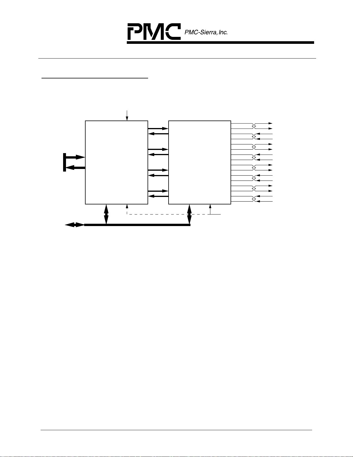
Figure 1 - Example 1. T1 or E1 Multi-PHY ATM UNI
1.544 MHz Transmit Reference Clock
DSX-1
or
E1
Analog
Interfaces
SCI-PHYTM
Multi-PHY
ATM Cell Bus
PM7344
S/UNI-MPH
Quad T1/E1
Multi-PHY
User Network Interface
PM4314
QDSX
Quad DSX-1/E1
Analog Line Interface
Generic
Microprocessor
Bus
Or 12.352 MHz
Crystal Oscillator Clock
37.056 MHz
Example 1 shows the PM7344 S/UNI-MPH used with the PM4314 QDSX to
implement a quad T1/E1 UNI where the DS1 or E1 signals are presented on
DSX-1 or E1 electrical interfaces.
In this example, the DSX-1 or E1 line interface functions are provided by the
QDSX and the DS1 or E1 framing functions are provided by the S/UNI-MPH.
Note that many other standard DSX-1 or E1 line interface devices are also
compatible with the S/UNI-MPH. The S/UNI-MPH also provides the ATM cell
processing functions associated with the PHY layer, including the implementation
of a SCI-PHY multi-PHY interface to the ATM layer device(s). The combination
of the QDSX device with the S/UNI-MPH allows both ANSI/ITU compliant DSX1/E1 analog signals and ATM Forum UNI 3.1 and ITU G.804 compliant DS1/E1
digital signals to be processed. The UNI 3.1 and G.804 specifications define
ATM cell mappings for a variety of transmission formats, including the 1.544
Mbit/s DS1 and the 2.048 Mbit/s E1 formats.
PROPRIETARY AND CONFIDENTIAL TO PMC-SIERRA, INC., AND FOR ITS CUSTOMERS’ INTERNAL USE 10
PM7344 S/UNI-MPH
DATA SHEET
PMC-950449 ISSUE 6 MULTI-PHY USER NETWORK INTERFACE
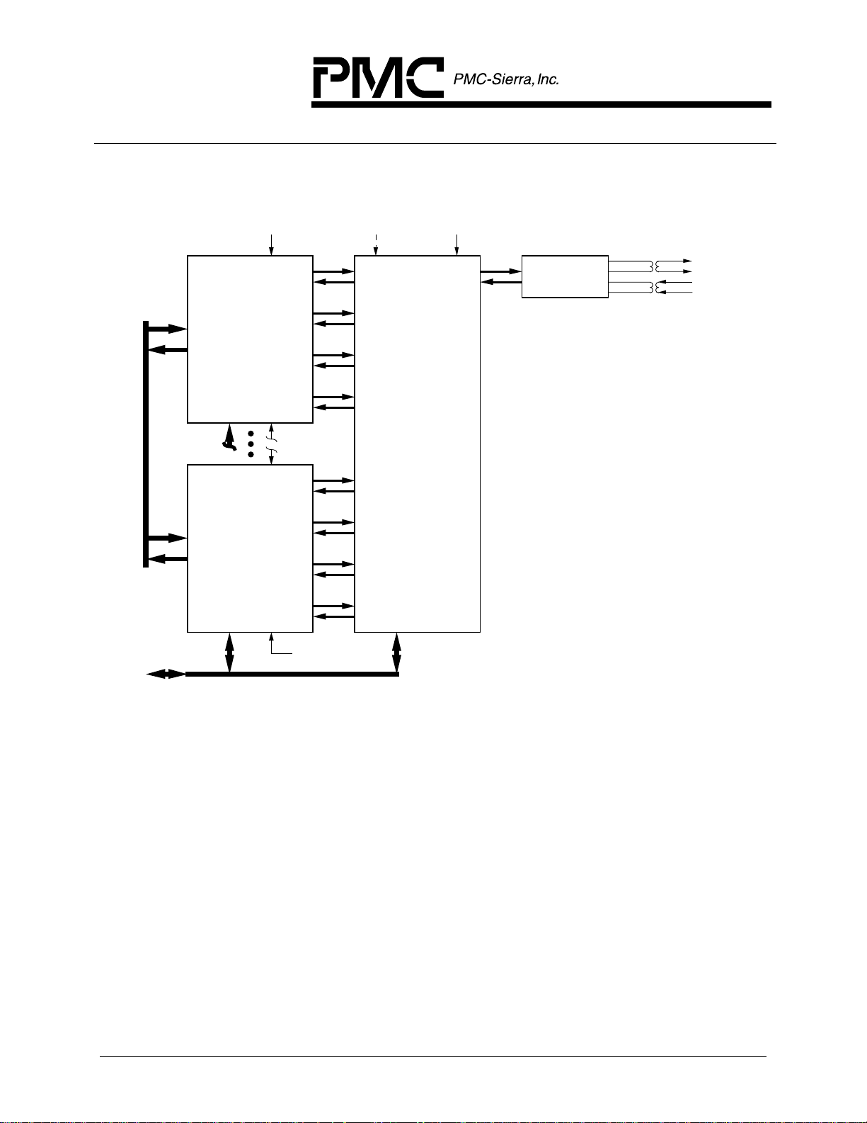
Figure 2 - Example 2. DS3 Port Carrying Multiplexed T1 or E1 ATM UNI
Signals
SCI-PHYTM
Multi-PHY
ATM Cell Bus
1.544 MHz
Transmit
Reference Clock
PM7344
S/UNI-MPH
Quad T1/E1
Multi-PHY
User Network Interface
PM7344
S/UNI-MPH
Quad T1/E1
Multi-PHY
User Network Interface
# 1
12.352 MHz
1.544 MHz
# 7
6.312 MHz
Optional Transmit
Reference Clock
PM8313
D3MX
Integrated M13
Multiplexer
44.736 MHz
Transmit
Reference Clock
DSX-3
Line Interface With
Clock Recovery
DSX-3
Analog
Interface
Generic
Microprocessor
Bus
Crystal Oscillator Clock
12.352 MHz
Example 2 shows seven PM7344 S/UNI-MPH devices used with a PM8313
D3MX device and a generic DSX-3 LIU device being used to implement a DS3
port where the DS3 carries a multiplex of DS1 (or E1) UNI signals.
In this example, each S/UNI-MPH provides four duplex DS1 signals to the D3MX
device which, in turn, performs the asynchronous multiplex and demultiplex
function required to map these into a DS3 signal. The D3MX may use the
traditional M23 format or may use the C-bit parity format when performing this
multiplex. Note that the D3MX may also be configured for G.747 multiplexing of
three E1 signals into each of the seven DS2 signals within the overall DS3
signal. Many generic DSX-3 line interface unit devices may be used with the
D3MX to implement a DSX-3 electrical interface on the high speed line side of
such a system. Each S/UNI-MPH device implements the T1 or E1 UNI function
for four T1 or E1 streams. The seven S/UNI-MPH devices may be serviced by a
common ATM layer device through a shared (SCI-PHY
TM
) multi-PHY bus.
PROPRIETARY AND CONFIDENTIAL TO PMC-SIERRA, INC., AND FOR ITS CUSTOMERS’ INTERNAL USE 11
PM7344 S/UNI-MPH
DATA SHEET
PMC-950449 ISSUE 6 MULTI-PHY USER NETWORK INTERFACE
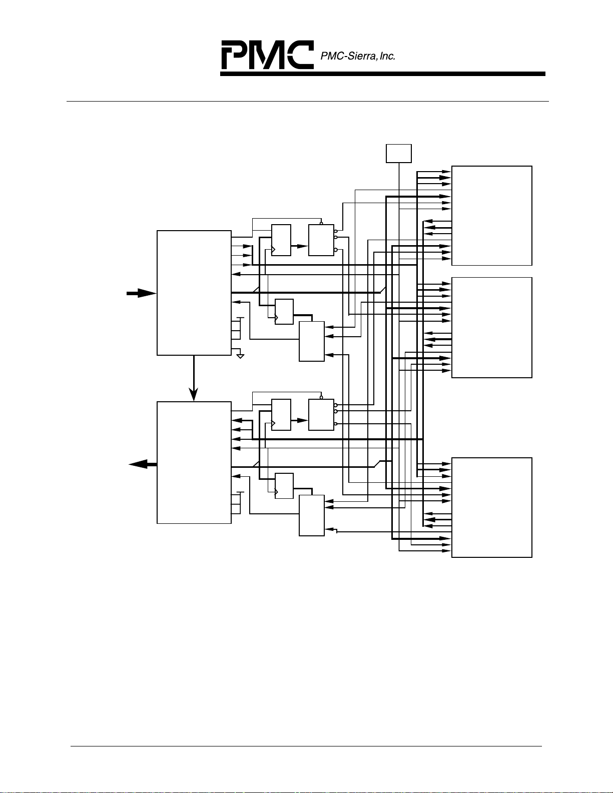
Figure 3 - Example 3. Multi-PHY Addressing Application
OSC
TSOC
TDAT[7:0]
TXPRTY
TCAMPH
TWA[1:0]
TWRMPHB
TFCLK
S/UNI-MPH
RSOC
RDAT[7:0]
RXPRTY
RCAMPH
RRA[1:0]
RRDMPHB
RFCLK
TSOC
TDAT[7:0]
TXPRTY
TCAMPH
TWA[1:0]
TWRMPHB
TFCLK
RSOC
RDAT[7:0]
RXPRTY
RCAMPH
RRA[1:0]
RRDMPHB
RFCLK
TSOC
TDAT[7:0]
TXPRTY
TCAMPH
TWA[1:0]
TWRMPHB
TFCLK
RSOC
RDAT[7:0]
RXPRTY
RCAMPH
RRA[1:0]
RRDMPHB
RFCLK
#1
S/UNI-MPH
#2
. . .
S/UNI-MPH
#N
Single-PHY
or
Multi-PHY
interface to
switch
Single-PHY
or
Multi-PHY
interface to
switch
UTOPIA
LEVEL 2
COMPLIANT
EGRESS
DEVICE
Backward OAM
& Loopback Cells
UTOPIA
LEVEL 2
COMPLIANT
INGRESS
DEVICE
ORDENB[1]
ODAT[7:0]
OPRTY[0]
OSOC
OFCLK
OAVALID
OADDR[4:0]
OCA[1]
OMASTER
OPOLL
OBUS8
OTSEN
IWRENB[1]
IDAT[7:0]
IPRTY[0]
ISOC
IFCLK
IAVALID
IADDR[4:0]
ICA[1]
IMASTER
IPOLL
IBUS8
decoder
N-to-1
mux
decoder
N-to-1
mux
E
3-to-N
E
3-to-N
. . .
1:0
. . .
. . .
1:0
. . .
load
D
Q
4:2
D
Q
load
D
Q
4:2
D
Q
Example 3 shows N (where N is a number from 1 to 8) PM7344 S/UNI-MPH
devices used with UTOPIA Level 2 compliant ingress and egress devices.
The S/UNI-MPH supports PHY address polling by sampling the two least
significant address bits (RRA[1:0] and TWA[1:0]) and generating the cell
available status for the selected PHY entity. It also holds the last state of
RRA[1:0] and TWA[1:0] before the assertion of RRDMPHB and TWRMPHB,
respectively, thus latching the PHY address resolved by the polling process. The
only support logic is that required to select between the S/UNI-MPH devices.
PROPRIETARY AND CONFIDENTIAL TO PMC-SIERRA, INC., AND FOR ITS CUSTOMERS’ INTERNAL USE 12

PM7344 S/UNI-MPH
DATA SHEET
PMC-950449 ISSUE 6 MULTI-PHY USER NETWORK INTERFACE
Note that the oscillator can be at any frequency less than or equal to 25 MHz.
For the DS-1 case the data rate is 1.536 Mbits/s (1.544 Mbits/s * 192 payload
bits per frame / 193 bits per frame) for each DS-1 port. Thus, the aggregate
throughput is less than 6.144 Mbyte/s with 32 DS-1 ports; therefore, the clock
oscillator frequency can be as low as 6.5 MHz.
PROPRIETARY AND CONFIDENTIAL TO PMC-SIERRA, INC., AND FOR ITS CUSTOMERS’ INTERNAL USE 13
PM7344 S/UNI-MPH
DATA SHEET
PMC-950449 ISSUE 6 MULTI-PHY USER NETWORK INTERFACE
5 BLOCK DIAGRAM
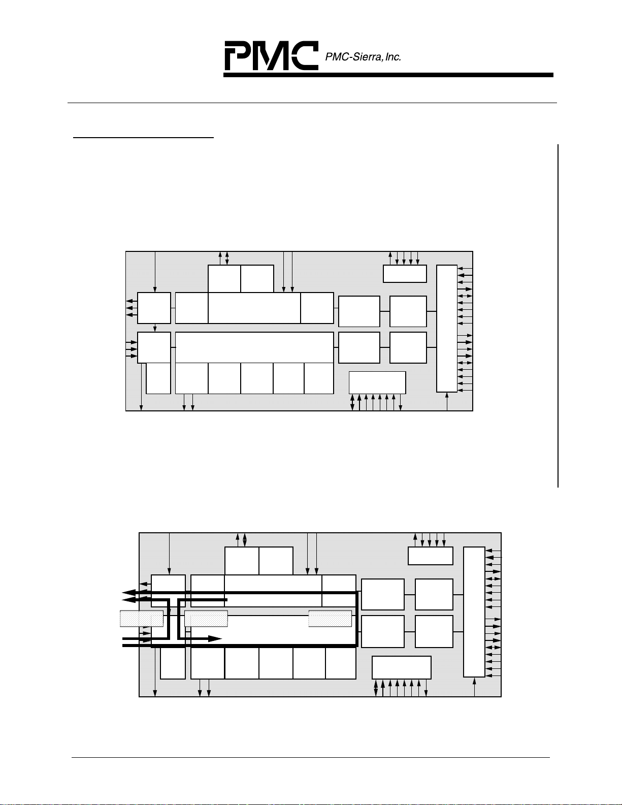
Figure 4 - Normal Operating Mode
TCLKO[4:1]
TDP/TDD[4:1]
TDN/TOHO[4:1]
RCLKI[4:1]
RDP/RDD[4:1]
RDN/RLCV/
ROH[4:1]
XCLK
Digital
Transmit
Interface
Digital
Receive
Interface
Pulse
Density
Violation
Detector
RCLKO
Pulse
Density
Enforcer
HDLC
Receiver
RDLSIG/RDLINT[4:1]
RDLCLK/RDLEOM[4:1]
TDLCLK/TDLUDR[4:1]
TDLSIG/TDLINT[4:1]
HDLC
Transmitter
Bit
Oriented
Code
Receiver
Figure 5 - Loopback Modes
Bit
Oriented
Code
Transmitter
T1/E1
Framing
Insertion
T1/E1
Framer
Performance
Monitor
TCLKI
Inband
Code
Detector
TFPI/TOHI
Inband
Loopback
Code
Generator
Alarms
Integrator
Tx ATM Cell
Processor
Rx ATM Cell
Processor
Microprocessor I/F
ALE
D[7:0]
A[10:0]
CSB
TDO
JTAG Test
Access Port
RDB
WRB
TDI
Tx ATM
4 Cell
FIFO
Rx ATM
4 Cell
FIFO
INTB
RSTB
TCK
TMS
TRSTB
TSOC
TDAT[7:0]
TXPRTY
TCA[4:1]
TCAMPH/TWRENB[4]
TWA[1]/TWRENB[3]
TWA[0]/TWRENB[2]
TWRMPHB /TWRENB[1]
MPHEN
TFCLK
RSOC
RDAT[7:0]
RXPRTY
RCA[4:1]
RCAMPH/RRDENB[4]
RRA[1]/RRDENB[3]
RRA[0]/RRDENB[2]
RRDMPHB /RRDENB[1]
RFCLK
Multi-
PHY
I/F
Bit
Oriented
Code
Transmitter
T1/E1
Framing
Insertion
T1/E1
Framer
Performance
Monitor
Inband
Code
Detector
Inband
Loopback
Code
Generator
PAYLOAD
LOOPBACK
Alarms
Integrator
JTAG Test
Access Port
Tx ATM Cell
Processor
Rx ATM Cell
Processor
Microprocessor I/F
Tx ATM
4 Cell
FIFO
Rx ATM
4 Cell
FIFO
Multi-
PHY
I/F
LINE
LOOPBACK
Digital
Transmit
Interface
Digital
Receive
Interface
Pulse
Density
Violation
Detector
Pulse
Density
Enforcer
DIAGNOSTIC
LOOPBACK
HDLC
Receiver
HDLC
Transmitter
Bit
Oriented
Code
Receiver
PROPRIETARY AND CONFIDENTIAL TO PMC-SIERRA, INC., AND FOR ITS CUSTOMERS’ INTERNAL USE 14
 Loading...