

Page 1
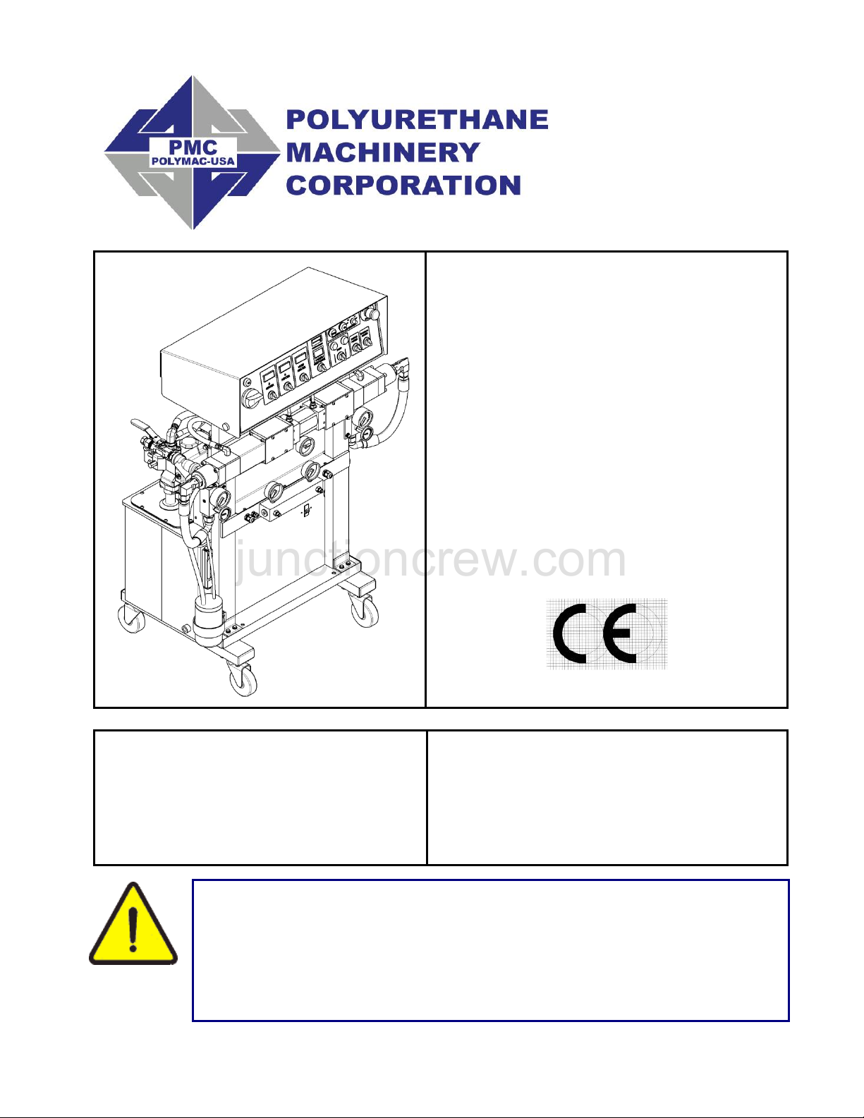
PH/PHX-2
Proportioner
For Professional Use Only
Not approved for use in European
explosive atmosphere locations
Manual
Ref. # MN-04009
REVISION 1.0
Polyurethane Machinery Corp.
Corporate: 1 KOMO Drive, Lakewood, NJ 08701
Manufacturing: 2 KOMO Drive, Lakewood, NJ 08701
Phone: 732-415-4400 Fax: 732-364-4025
http://www.polymac-usa.com
junctioncrew.com
Before installing the PH Series Proportioner and start-up, carefully
read all the technical and safety documentation included in this
manual. Pay special attention to the information in order to know
and understand the operation and the conditions of use of the PH
Series Proportioner. All of the information is aimed at improving
user safety and avoiding possible breakdowns from the incorrect use
of the PH Series Proportioner.
Page 2

PH/PHX-2 Manual
junctioncrew.com
TABLE OF CONTENTS
WARRANTY ................................................................................................................... 4
SAFETY AND HANDLING ............................................................................................. 6
CHARACTERISTICS ...................................................................................................... 8
Principal Heating System ............................................................................................. 8
Hose Heating System .................................................................................................. 8
Double Acting Opposed Piston Metering Pumps ......................................................... 8
Pressure Balance Control System ............................................................................... 9
TECHNICAL SPECIFICATIONS .................................................................................. 10
Electrical .................................................................................................................... 10
Mechanical ................................................................................................................ 11
DESCRIPTION .............................................................................................................. 12
INSTALLATION ............................................................................................................ 17
PROPORTIONER PURGING ....................................................................................... 24
PRESSURE BALANCE CONTROL ............................................................................. 26
Operation ................................................................................................................... 26
DIGITAL TEMPERATURE CONTROLLER .................................................................. 27
START-UP .................................................................................................................... 28
SHUT-DOWN ................................................................................................................ 30
TROUBLESHOOTING .................................................................................................. 31
Heaters ...................................................................................................................... 32
Hydraulic Drive System ............................................................................................. 35
Metering Pump Line ................................................................................................... 37
Hose Heating ............................................................................................................. 41
Pressure Balance Control .......................................................................................... 44
MAINTENANCE ............................................................................................................ 45
Inlet Material Screens ................................................................................................ 46
Hydraulic Drive System ............................................................................................. 47
Metering Pump Line ................................................................................................... 48
Material Heater .......................................................................................................... 49
2
Page 3

PH/PHX-2 Manual
junctioncrew.com
HYDRAULIC OIL SPECIFICATIONS ........................................................................... 51
REPLACEMENT KITS .................................................................................................. 52
PARTS IDENTIFICATION ............................................................................................ 53
FRAME ASSEMBLY .................................................................................................. 53
HYDRAULIC MANIFOLD ASSEMBLY ...................................................................... 55
EXIT MANIFOLD ASSEMBLY ................................................................................... 56
HYDRAULIC SEAL ASSEMBLY ............................................................................... 57
HYDRAULIC PISTON ASSEMBLY ........................................................................... 58
HYDRAULIC CYLINDER ASSEMBLY ....................................................................... 59
A & R SINGLE PUMP ASSEMBLY (16:1) ................................................................. 61
PA-044 OUTLET BODY ASSEMBLY ........................................................................ 62
PA-044 PISTON ASSEMBLY .................................................................................... 63
PA-044 INLET BODY ASSEMBLY ............................................................................ 64
A & R SINGLE PUMP ASSEMBLY (30:1) ................................................................. 65
PAX-044 OUTLET BODY ASSEMBLY ...................................................................... 66
PAX-044 PISTON ASSEMBLY .................................................................................. 67
PAX-044 INLET BODY ASSEMBLY .......................................................................... 68
PUMPLINE ASSEMBLY ............................................................................................ 69
PUMPLINE ASSEMBLY ............................................................................................ 71
“A” INLET MANIFOLD ASSEMBLY ........................................................................... 73
“R” INLET MANIFOLD ASSEMBLY ........................................................................... 74
PREHEATER ASSEMBLY ........................................................................................ 75
MOTOR LINE ASSEMBLY (1 PHASE) ...................................................................... 78
MOTOR LINE ASSEMBLY (3 PHASE) ...................................................................... 80
FINAL ASSEMBLY .................................................................................................... 82
HOSES ...................................................................................................................... 87
EXIT MANIFOLD ACCESSORY ................................................................................ 88
MANUAL REVISIONS .................................................................................................. 89
3
Page 4

PH/PHX-2 Manual
junctioncrew.com
WARRANTY
Polyurethane Machinery Corporation (hereinafter “PMC”) provides this LIMITED WARRANTY
(hereinafter “Warranty”) to the original purchaser (hereinafter “Customer”) covering this
equipment and the original PMC manufactured accessories delivered with the equipment
(hereinafter “Product”) against defects in material or workmanship of the Product (hereinafter
“Defect” or “Defective”) for a period of one (1) year from the date of first purchase as shown on
the original PMC invoice (hereinafter “Warranty Period”).
If during the Warranty Period under normal use, the Product is suspected by Customer to be
Defective in material or workmanship, it is Customer’s responsibility to contact PMC and return
the Product to PMC as directed by PMC, freight prepaid. If PMC determines that the Product is
Defective and that such Defect is covered by this Warranty, PMC will credit Customer for the
reasonable freight charges incurred by Customer in returning the Defective Product to PMC,
and PMC (or its authorized agent) will, at PMC’s option, repair or replace the Product, subject to
the following:
Original Invoice: The original invoice must be kept as proof of the date of first sale and the
Product serial number. The Warranty does not cover any Product if the Original Invoice
appears to have been modified or altered, or when the serial number on the Product appears to
have been altered or defaced.
Product Maintenance: It is the Customer’s responsibility to maintain the Product properly. See
your maintenance schedule and owner’s manual for details. The Warranty does not cover an
improperly maintained Product.
Non-PMC Components and Accessories: Non-PMC manufactured components and accessories
that are used in the operation of the Product are not covered by this Warranty. Such
components and accessories shall be subject to the warranty offered to the Customer, if any, by
the original manufacturer of such component or accessory.
Other Warranty Exclusions: The Warranty does not cover any Product that PMC determines has
been damaged or fails to operate properly due to misuse, negligence, abuse, carelessness,
neglect, or accident. By way of example only, this includes:
Normal wear and tear.
Improper or unauthorized installation, repair, alteration, adjustment or modification of the
product.
Use of heating devices, pumping equipment, dispensers, or other parts or accessories
with the product that have not been approved or manufactured by PMC.
Failure to follow the operating instructions and recommendations provided by PMC.
Cosmetic damage.
Fire, flood, “acts of God,” or other contingencies beyond the control of PMC.
4
Page 5

PH/PHX-2 Manual
junctioncrew.com
THE WARRANTY DESCRIBED HEREIN IS THE EXCLUSIVE REMEDY FOR THE
CUSTOMER AND IS IN LIEU OF ALL OTHER WARRANTIES, EXPRESS, IMPLIED,
STATUTORY OR OTHERWISE, AND THE IMPLIED WARRANTIES OF
MERCHANTABILITY AND FITNESS FOR A PARTICULAR PURPOSE AND ALL
OTHER WARRANTIES ARE HEREBY DISCLAIMED. TO THE FULLEST EXTENT
PERMITTED BY LAW, PMC SHALL NOT BE RESPONSIBLE, WHETHER BASED IN
CONTRACT, TORT (INCLUDING, WITHOUT LIMITATION, NEGLIGENCE),
WARRANTY OR ANY OTHER LEGAL OR EQUITABLE GROUNDS, FOR ANY
CONSEQUENTIAL, INDIRECT, INCIDENTAL, LOST PROFITS, SPECIAL, PUNITIVE
OR EXEMPLARY DAMAGES, WHETHER TO PERSON OR PROPERTY, ARISING
FROM OR RELATING TO THE PRODUCT, EVEN IF PMC HAS BEEN ADVISED OF
THE POSSIBILITY OF SUCH LOSSES OR DAMAGES.
Non-Warranty Service by PMC: If PMC determines that the suspected Defect of the Product is
not covered by this Warranty, disposition of the Product will be made pursuant to the terms and
conditions of PMC’s written estimate on a time and materials basis.
Continuing Warranty for Products Repaired or Replaced under Warranty: Following the repair
or replacement of a Product covered by this Warranty, such Product will continue to be subject
to the original Warranty for the remainder of original Warranty Period or for three (3) months
from the repair or replacement date, whichever is longer.
No Rights Implied: Nothing in the sale, lease or rental of any Product by PMC shall be
construed to grant any right, interest or license in or under any patent, trademark, copyright,
trade secret or other proprietary right or material owned by anyone; nor does PMC encourage
the infringement of same.
Exclusive Warranty: This writing is the final, complete, and exclusive expression of the Warranty
covering the Product. Any statements made by PMC, its employees or agents that differ from
the terms of this Warranty shall have no effect. It is expressly understood that Customer’s
acceptance of this Warranty, by performance or otherwise, is upon and subject solely to the
terms and conditions hereof, and any additional or different terms and conditions proposed or
expressed by Customer or anyone, whether in writing or otherwise, are null and void unless
specifically agreed to in writing by an Officer of PMC.
5
Page 6

PH/PHX-2 Manual
junctioncrew.com
SAFETY AND HANDLING
This chapter contains important information on the safety, handling, and use of your PH
Series Proportioner.
Before installing the PH Series Proportioner and start-up,
carefully read all the technical and safety documentation
included in this manual. Pay special attention to the
information to know and understand the operation and the
conditions of use of the PH Series Proportioner. All of the
information is aimed at enhancing User Safety and
avoiding possible breakdowns derived from the incorrect
use of the PH Series Proportioner.
WARNING! Symbol is presented in front of information to alert of a
situation that might cause serious injuries if the instructions are not
followed.
CAUTION! Symbol is presented in front of information that indicates how to
avoid damage to the Proportioner or how to avoid a situation that could
cause minor injuries.
NOTE! Symbol is presented in front of relevant information of a procedure
being carried out.
Careful study of this manual will enable the operator to know the characteristics of the
PH Series Proportioner and the operating procedures. By following the instructions and
recommendations contained herein, you will reduce the potential risk of accidents in the
installation, use, and maintenance of the PH Series Proportioner. You will provide a
better opportunity for greater output, incident-free operation for a longer time, and the
possibility of detecting and resolving problems quickly and simply.
Keep this Operations Manual for future consultation of useful information at all times. If
you lose this manual, ask for a new copy from your PMC Service Center or go on line at
our web site (www.polymac-usa.com).
6
Page 7

PH/PHX-2 Manual
junctioncrew.com
The PH Series Proportioner has been designed and built for the application of polyurea
chemical systems, polyurethane foam chemical systems, and some two-component epoxy
systems.
WARNING! The design and configuration of the PH Series Proportioner
does not allow its use in potentially explosive atmospheres or the pressure
and temperature limits described in the technical specifications of this
manual to be exceeded.
Always use liquids and solvents that are compatible with the unit. If in doubt, consult your
authorized PMC distributor.
When working with the PH Series Proportioner, it is recommended that the operator wear
suitable clothing and elements of personal protection, including, without limitation, gloves,
protective goggles, safety footwear and face masks. Use breathing equipment when working
with the PH Series Proportioner in enclosed spaces or in areas with insufficient ventilation. The
introduction and follow-up of safety measures must not be limited to those described in this
manual. Before starting up the PH Series Proportioner, a comprehensive analysis must be
made of the risks derived from the products to be dispensed, the type of application, and the
working environment.
To prevent possible injury caused by incorrect handling of the raw
materials and solvents used in the process, carefully read the
Material Safety Data Sheet (MSDS)provided by your supplier.
Deal with the waste caused according to current regulations.
To avoid damage caused by the impact of pressurized fluids, do not
open any connection or perform maintenance work on components
subject to pressure until the pressure has been completely
eliminated.
Use suitable protection when operating, maintaining or being present
in the area where the equipment is functioning. This includes, but is
not limited to, the use of protective goggles, gloves, shoes and safety
clothing and breathing equipment.
The equipment includes components that reach high temperatures
and can cause burns. Hot parts of the equipment must not be
handled or touched until they have cooled completely.
To prevent serious injury through crushing or amputation, do not
work with the equipment without the safety guards installed on the
moving parts. Make sure that all the safety guards are correctly
reinstalled at the end of the repair or maintenance work of the
equipment.
7
Page 8

PH/PHX-2 Manual
100% circumferential coverage produces the
most uniform distribution of heat available.
junctioncrew.com
CHARACTERISTICS
The PH Series Proportioner has been designed and built for the application of polyurea
chemical systems, polyurethane foam chemical systems, and some specific twocomponent epoxy systems.
Principal Heating System
The Proportioner consists of one (1) Material Heater without internal seals. The Heater
has three (3) Heating Elements per fluid side rated at 1,250, 1,500, or 1750 watts, each
giving the Proportioner a total heat output of 7,500, 9,000, or 10,500 watts and the
necessary control and safety components for their precise operation. The Material
Heater design allows for a controlled and precise temperature differential (ΔT) and
material application temperatures of up to 190º F under ambient temperatures.
Hose Heating System
The system is designed with a 3 KVA Isolation Transformer that enables effective
heating of up to a total hose length of 310 feet (also available with a 2KVA transformer
and a 5 KVA transformer for maximum hose lengths of 210 and 410, respectively). The
system includes an innovative hose heating concept in which the continuous braid
tinned-copper jacket is distributed evenly around the circumference of the hose
providing a uniform heating watt density and precise control of the material application
temperature. This hose heating element design is extremely resistant to fatigue failure.
Double Acting Opposed Piston Metering Pumps
The opposed double acting Pump Line is driven by a double ended Hydraulic Cylinder.
The in-line pump system with opposed piston pumps provides a constant volume and
guarantees uniform pressures in both directions of pump movement.
8
Page 9

PH/PHX-2 Manual
1. Power supply
2. “A” side pressure reading
3. “R” side pressure reading
4. Maximum pressure
5. Maximum allowable
pressure differential
Logic Box
1. Continue pumping material
OR
2. Shut off pumps
junctioncrew.com
Pressure Balance Control System
The Pressure Balance Control (PBC) system performs an automatic shutdown when a chemical
imbalance occurs. When the system is turned off, the Proportioner will perform as if there is no PBC
system and will continue pumping material. When the system is turned on, it will continually monitor the
pressure between the two chemicals (known as the pressure differential). If the pressure differential
becomes equal to or greater than the maximum allowable pressure differential, the pumps will be shut
off.
The Pressure Balance Control system can be simplified into a logic box diagram with inputs and outputs.
There are five inputs: the power supply from the main console, the pressure readings from each
chemical, the maximum pressure, and the maximum allowable pressure differential. Inside the logic box,
the actual pressure differential of the chemicals is compared to the maximum allowable pressure
differential. Depending on the circumstances of all five inputs, there are only two possible outputs: either
the pumps will continue to pressurize and move material, or the pumps will shut off and flow will be lost.
Logic Box Representation
9
Page 10

PH/PHX-2 Manual
junctioncrew.com
TECHNICAL SPECIFICATIONS
Electrical
Main Voltage: __________________________________________3 x 208-230V, 50/60Hz
Electrical Consumption: PH-2, 2000 PSI (2 x 3.75 kW Heaters) _______ 40 A @ 3 x 230V
Electrical Consumption: PH-2, 2000 PSI (2 x 4.50 kW Heaters) _______ 46 A @ 3 x 230V
Electrical Consumption: PH-2, 2000 PSI (2 x 5.25 kW Heaters) _______ 51 A @ 3 x 230V
Electrical Consumption: PHX-2, 3000 PSI (2 x 5.25 kW Heaters) _______ 51 A @ 3 x 230V
Main Voltage: __________________________________________1 x 208-230V, 50/60Hz
Electrical Consumption: PH-2, 2000 PSI (2 x 3.75 kW Heaters) _______ 61 A @ 1 x 230V
Electrical Consumption: PH-2, 2000 PSI (2 x 4.50 kW Heaters) _______ 67 A @ 1 x 230V
Electrical Consumption: PH-2, 2000 PSI (2 x 5.25 kW Heaters) _______ 72 A @ 1 x 230V
Electrical Consumption: PHX-2, 3000 PSI (2 x 5.25 kW Heaters) _______ 72 A @ 1 x 230V
Main Voltage: _____________________________________________ 3 x 380V, 50/60Hz
Electrical Consumption: PH-2, 2000 PSI (2 x 3.75 kW Heaters) _______ 40 A @ 3 x 380V
Electrical Consumption: PH-2, 2000 PSI (2 x 4.50 kW Heaters) _______ 46 A @ 3 x 380V
Electrical Consumption: PH-2, 2000 PSI (2 x 5.25 kW Heaters) _______ 51 A @ 3 x 380V
Electrical Consumption: PHX-2, 3000 PSI (2 x 5.25 kW Heaters) _______ 51 A @ 3 x 380V
Material Heater Power: PH-2 (2 x 3.75 kW)________________________________ 7.5 kW
Material Heater Power: PH-2 (2 x 4.50 kW)________________________________ 9.0 kW
Material Heater Power: PH-2 (2 x 5.25 kW)_______________________________ 10.5 kW
Material Heater Power: PHX-2 (2 x 5.25 kW) _____________________________ 10.5 kW
Hose Transformer Power: (70 V) _________________________________________ 2 KVA
Hose Transformer Power: (90 V) _________________________________________ 3 KVA
Hose Transformer Power: (120 V) ________________________________________ 5 KVA
Electrical Motor Power: PH-2 _____________________________________________ 3 hp
Electrical Motor Power: PHX-2 ___________________________________________ 5 hp
CAUTION! Inside the console is a Terminal Strip for
connecting the main power (wire not supplied) to the PH
Series Proportioner. This electrical connection must be
made only by a qualified electrician.
10
Page 11

PH/PHX-2 Manual
junctioncrew.com
Mechanical
Maximum working pressure PH-2 (123 pumps): ___________ 2,000 psi (14 MPa, 138 bar)
Maximum working pressure PHX-2 (61 pumps): ____________ 3,000 psi (21 MPa, 207 bar)
Maximum production ratio 1:1 PH-2 (123 pumps): _______________ 31 lb/min (14 kg/min)
Maximum production ratio 1:1 PHX-2 (61 pumps): ________________ 2.3 gpm (10.5 Lpm)
Minimum production: ________________________________________ 2 lb/min (1 kg/min)
Gallons per stroke PH-2 (123 pumps): ___________________ .01859 gal/stroke (.07037 L)
Gallons per stroke PHX-2 (61 pumps): ___________________ .00911 gal/stroke (.03449 L)
Strokes per 55 gal (200 L) drum PH-2 (123 pumps): _____________________ 2958 strokes
Strokes per 55 gal (200 L) drum PHX-2 (61 pumps): ____________________ 6037 strokes
Maximum hose length (2 KVA Transformer): ___________________________ 210 ft (64 m)
Maximum hose length (3 KVA Transformer): ___________________________ 310 ft (95 m)
Maximum hose length (5 KVA Transformer): __________________________ 410 ft (125 m)
Approximate weight (Hydraulic Tank empty): _______________________ 415 lbs (166 kg)
Approximate weight (Hydraulic Tank full @ 12 gal): __________________ 450 lbs (197 kg)
Dimensions: __________________________________________ 44in W x 22in D x 52in H
_____________________________________________ (111cm W x 55cm D x 132cm H)
11
Page 12
PH/PHX-2 Manual
junctioncrew.com
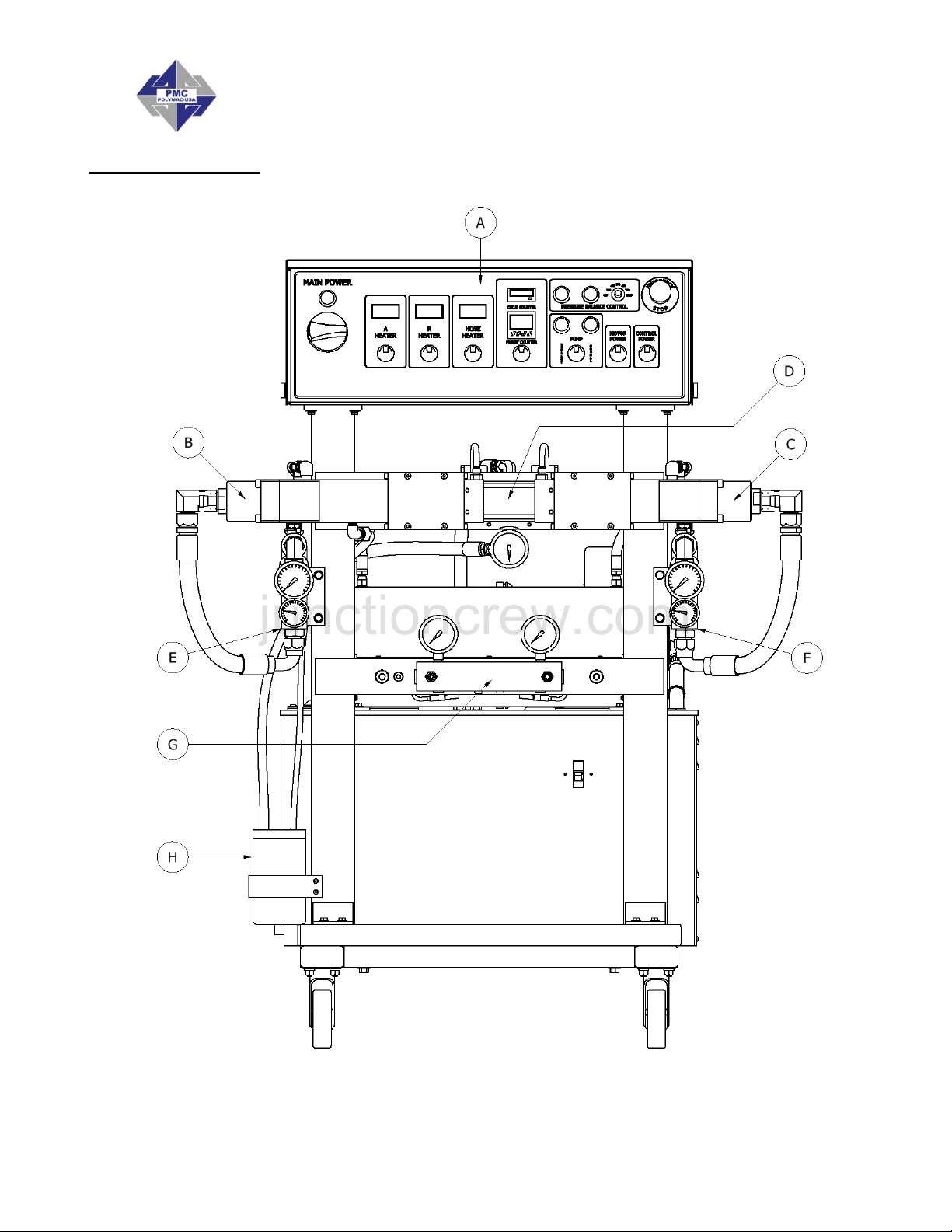
DESCRIPTION
PH-2/PHX-2 Proportioners
12
Page 13
PH/PHX-2 Manual
junctioncrew.com
PH-2/PHX-2 Proportioners
13
Page 14

PH/PHX-2 Manual
junctioncrew.com
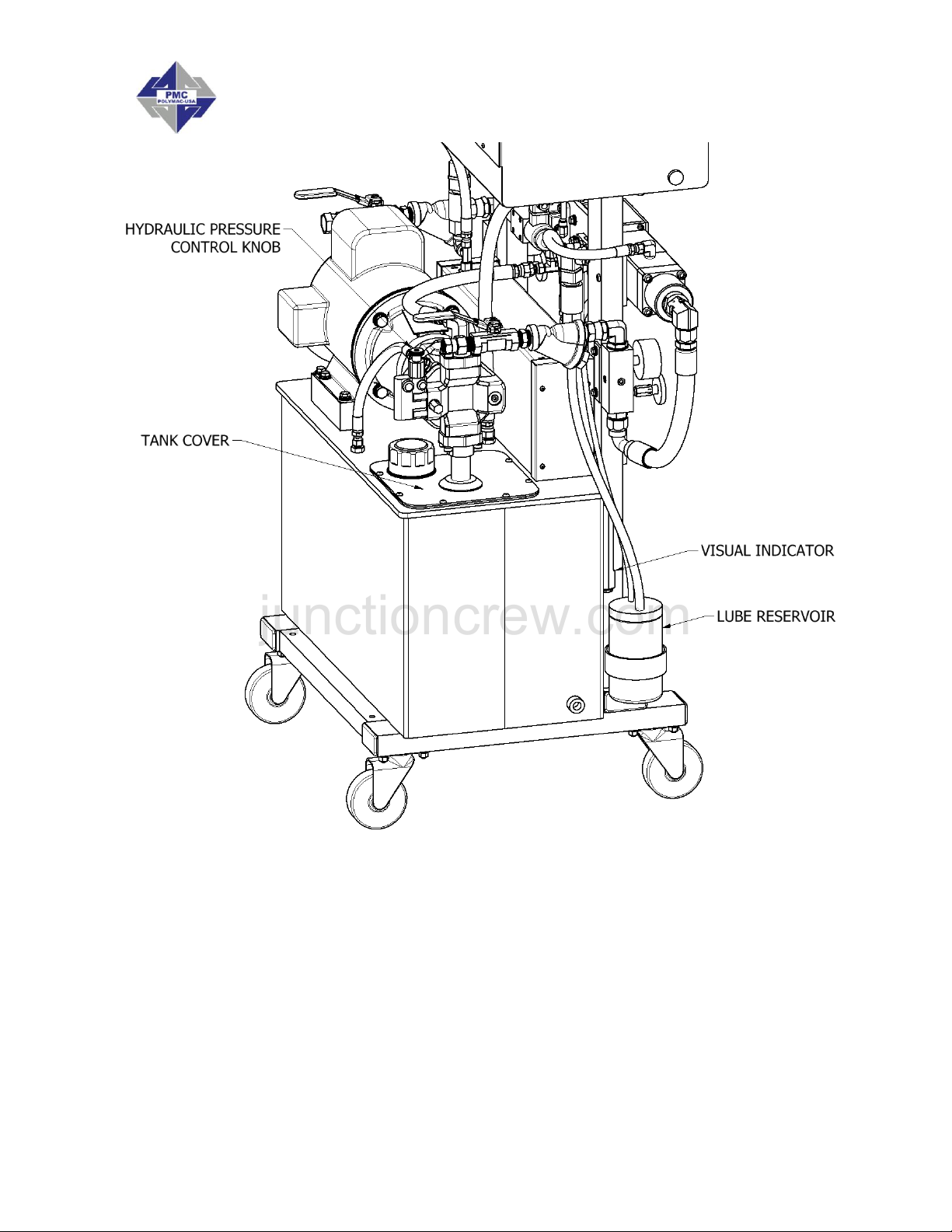
A. Control Panel
Controls and regulates the operation of the PH Series Proportioner.
B. Isocyanate (Iso, A) Metering Pump
Meters the Isocyanate material.
C. Polyol (Poly, R) Metering Pump
Meters the Polyol material.
D. Hydraulic Cylinder Assembly
Transfers power from hydraulic pump to material pumps.
E. Isocyanate (Iso, A) Inlet Manifold Assembly
Provides Isocyanate temperature and pressure readings prior to heating and
pressurizing
F. Polyol (Poly, R) Inlet Manifold Assembly
Provides Polyol temperature and pressure readings prior to heating and pressurizing
G. Exit Manifold Assembly
Provides pressure reading of material after heating and pressurizing
H. Isocyanate (Iso, A) Lube Reservoir
Provides lube to the Isocyanate pump shaft
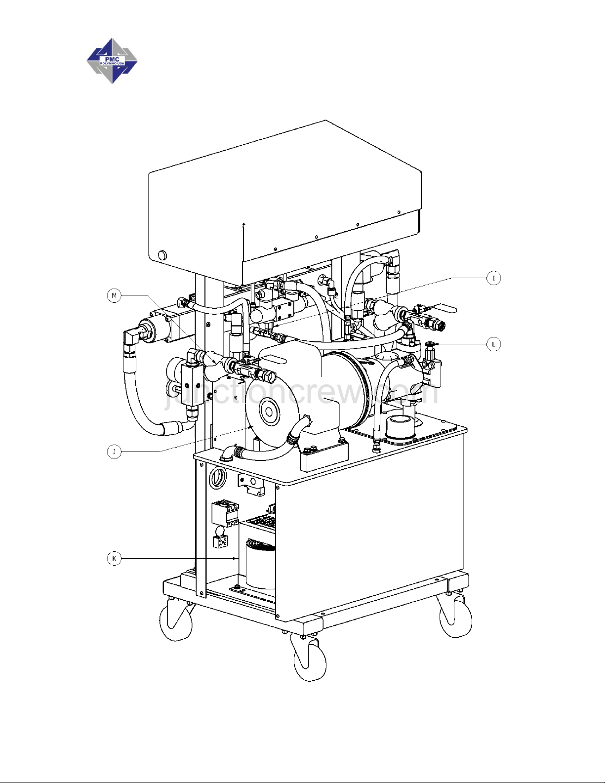
I. Hydraulic Manifold Assembly
Provides pressure reading of hydraulic fluid and controls direction of flow
J. Motor
Provides power for hydraulic pump.
K. Hose Heating Transformer – Right side, inside of hydraulic tank
Supplies the required voltage for material Heated Hoses
L. Hydraulic Pressure Control
Allows the pressure of the hydraulic system to be increased or decreased. Turn
clockwise to increase the pressure and counterclockwise to decrease. To regulate the
pressure of the hydraulic system, the NORMAL or RETRACT Pump Switch position
must be selected,
M. Inlet Material Strainer
Screens (60 mesh) material from bulk supply.
14
Page 15
PH/PHX-2 Manual
MODEL
PUMP SIZE
CYCLES PER GALLON
PH-2, 2000 PSI
123
27
PHX-2, 3000 PSI
61
55
junctioncrew.com
N. Main Power - Turns ON and OFF main power to the control panel. It must be turned
ON for any operation to be performed with the unit. When turned ON, the red pilot will
light.
O. Emergency Stop - Interrupts the PH- Series control power circuit to stop all motion
and heating.
P. Pump Switch
Off - Removes power from the pump circuit. The directional indicator lights will not be
lit.
Normal - Activates the normal operation of the machine. When the switch is ON, the
directional light corresponding to the stroke direction will light.
Retract - Sets the Piston Rod of the Iso (A) metering pump into the pump to prevent
crystallization of Iso (A) on the Piston Rod. Press the RETRACT key every time the
unit is stopped by the operator (see Shut-Down, page 30).
Q. Direction Indicator Lights - Indicates the movement direction of the Metering Pumps.
If excessive pressure is caused in the system, the pump circuit will be disabled and the
directional lights will be OFF.
R. Control Power - Turns ON and OFF the control power to the complete electrical
circuit including Heaters and Hose Heater.
S. Heater Temperature Switch – A (Iso), R (Poly), HOSE – Turns ON and OFF power
to the specific Heaters and Hose.
T. Temperature Controllers – Displays the temperature of the chemicals. See page 27
for detailed Temperature Controller instructions.
U. Totalizer – Indicates the number of pump cycles to calculate material usage.
15
Page 16

PH/PHX-2 Manual
junctioncrew.com
V. Auto Shut Down Switch - Turns ON and OFF power to the Auto Shut Down unit.
W. Auto Shut Down Counter – Used to set the amount of cycles required to prevent the
chemical drums from running dry, the machine will shut down when the preset cycles
expire. There is an on/off switch to activate this feature or deactivate and not use it,
see page 29.
X. Motor Switch - Turns ON and OFF the Electric/Hydraulic Motor. When turned ON,
the pilot will light. In the event of an overload of the Motor, pilot light will turn OFF and
Motor will stop.
Y. Pressure Balance Control Knob – Used to set the maximum allowable pressure
differential (in PSI) between the A (Iso) and R (Poly) pumps. See page 26 for more
information.
Z. Pressure Balance Control “ON” Light – Indicates that the Pressure Balance Control
system is on and functioning.
AA. Pressure Balance Control “FAULT” Light – Indicates that the pressure differential is
equal to or greater than the maximum allowable pressure differential.
16
Page 17
PH/PHX-2 Manual
L1
L2
1 phase x 230 Volt
L3
L2
L1
3 phase x 230 Volt
3 phase x 380 Volt
junctioncrew.com
INSTALLATION
WARNING! Use suitable protection and follow the recommendations in the
Safety Information enclosed and provided by material suppliers when installing
or working with the Proportioner.
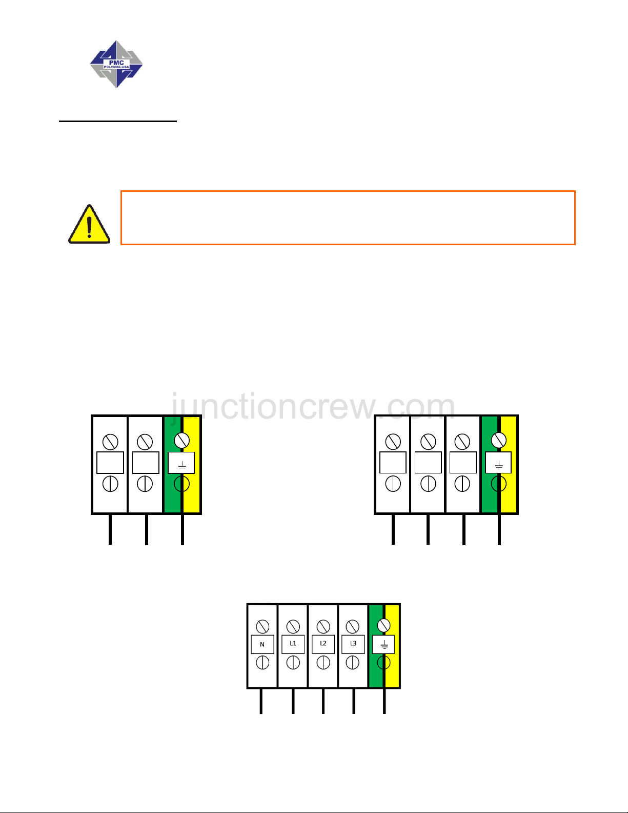
Inside the console is a Terminal Strip for connecting the
incoming power cable (not supplied). The electrical connection
of the Proportioner must be performed by a qualified electrician.
NOTE! To ensure the PH Series Proportioner works correctly, the electrical
supply must meet the specifications indicated on the Serial Number Placard
affixed to the Electrical Console.
CAUTION! Make sure the power cable is disconnected from the main power
source before connecting to the Terminal Strip in the Console.
17
Page 18

PH/PHX-2 Manual
junctioncrew.com
Follow the recommended procedure in the indicated order to install the Proportioner:
1. Insert the main power cable by passing it through the wire stop at the bottom of the
electrical console and connect as shown in the diagram above.
2. Fill the Hydraulic Reservoir with 10 gallons (37 Liters) of approved hydraulic fluid. See
page 51 for oil specifications.
NOTE! Do not fill the tank to maximum capacity; use the Visual Level
Indicator on the tank to make sure the amount of hydraulic fluid is not
more than 10 gal (37 L) or 80% of the tank maximum capacity.
3. Check the level of the hydraulic fluid in the Hydraulic Pump Case: Disconnect the
Hydraulic Hose from the 90 fitting and remove Fitting from Hydraulic Case. Add fluid
as required. Reattach Fitting and Hydraulic Hose. Turn the hydraulic pressure control
knob counter clockwise until it stops, that is the lowest hydraulic pressure setting.
18
Page 19
PH/PHX-2 Manual
junctioncrew.com
ENSURE THAT THE EMERGENCY STOP IS NOT ENGAGED
4. Three-phase Proportioner Only: Check the Electric Motor to ensure rotation is
clockwise when viewing the end of the Electric Motor. A counter clockwise rotation
indicates two of the incoming power leads need to be reversed.
CAUTION! Ensure Main Power Switch is OFF and incoming power is locked
OFF before reversing power leads.
Recheck rotation before proceeding with Installation.
5. Fill the Lube Reservoir with PMC Pump Lube or suitable diluents. It is not necessary
to prime the system.
19
Page 20
PH/PHX-2 Manual
junctioncrew.com
Heated Hose Installation
CAUTION! The material delivery Heated Hoses are color coded Red and
Blue allowing the user to recognize them. The Red corresponds to the
Isocyanate (Iso, A) and the Blue to the Polyol (Poly, R). To avoid connection
errors, the Coupling Connections of the Iso (A) and Poly (R) Heated Hoses
are also different sizes to ensure correct orientation.
NOTE! The material delivery Heated Hoses are capped at the ends to
prevent absorbing moisture. Do not remove caps until the Heated Hoses are
going to be installed on the Proportioner.
1. Lay out all the Heated Hose assemblies end to end aligning the Iso “A” (red) and Poly
“R” (blue) and connect the respective Coupling Connections using the appropriate
sized open-end wrench after ensuring Heated Hose assemblies lay flat.
CAUTION! Take care to not cross-thread or over-tighten the Coupling
Connections. Thread seal tape or compound is not recommended for this
tapered seat Coupling Connections.
2. Connect the material Heated Hoses to the outlets of the respective Heaters i.e. Iso (A)
Heated Hose to the Iso (A) Heater and the Poly (R) Heated Hose to the Poly (R)
Heater ensuring Heated Hose assemblies lay flat.
3. Connect Air Hose Coupling Connections.
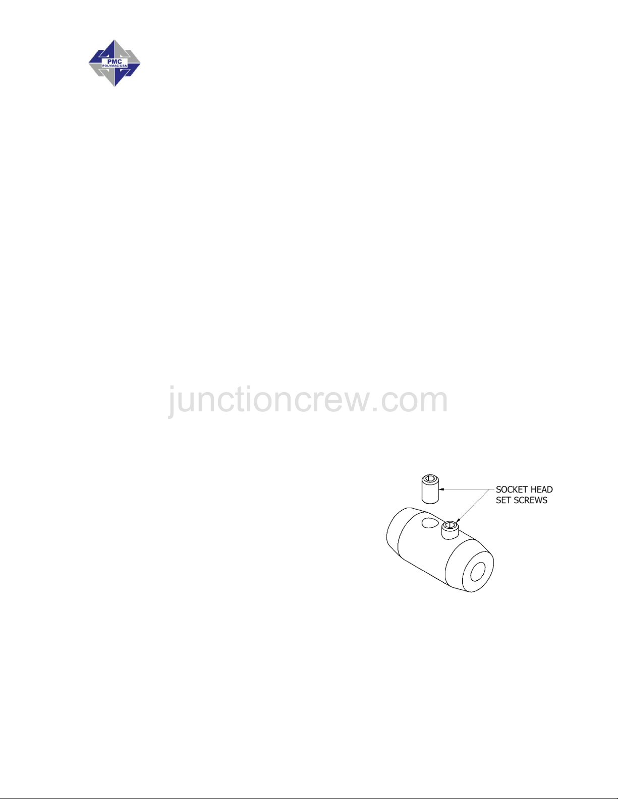
4. Connect the Heated Hose power wires to the “Fast-Lock” Connector (Part # KT00029A) coming from the Hose Heat Transformer as follows:
a. Loosen the Socket Head Set Screw to allow
insertion of the Heated Hose electrical wire
Terminal.
b. Insert the Terminal into the “Fast-Lock”
Connector Body.
c. Securely tighten the Socket Head Set Screw.
d. Install electrical tape around Connector Body.
NOTE! A good practice is to add some
dielectric grease (Permatex 67VR or equivalent) to the outside of the
Terminal, where the electrical connection is made, prior to insertion.
Repeat the above steps to connect the “Fast-Lock” Connectors that you will find on all
Heated Hose power wire.
CAUTION! Ensure the proper mechanical and electrical connections of the
Heated Hoses are made to avoid possible material leakage and Hose heat
problems.
20
Page 21
PH/PHX-2 Manual
junctioncrew.com
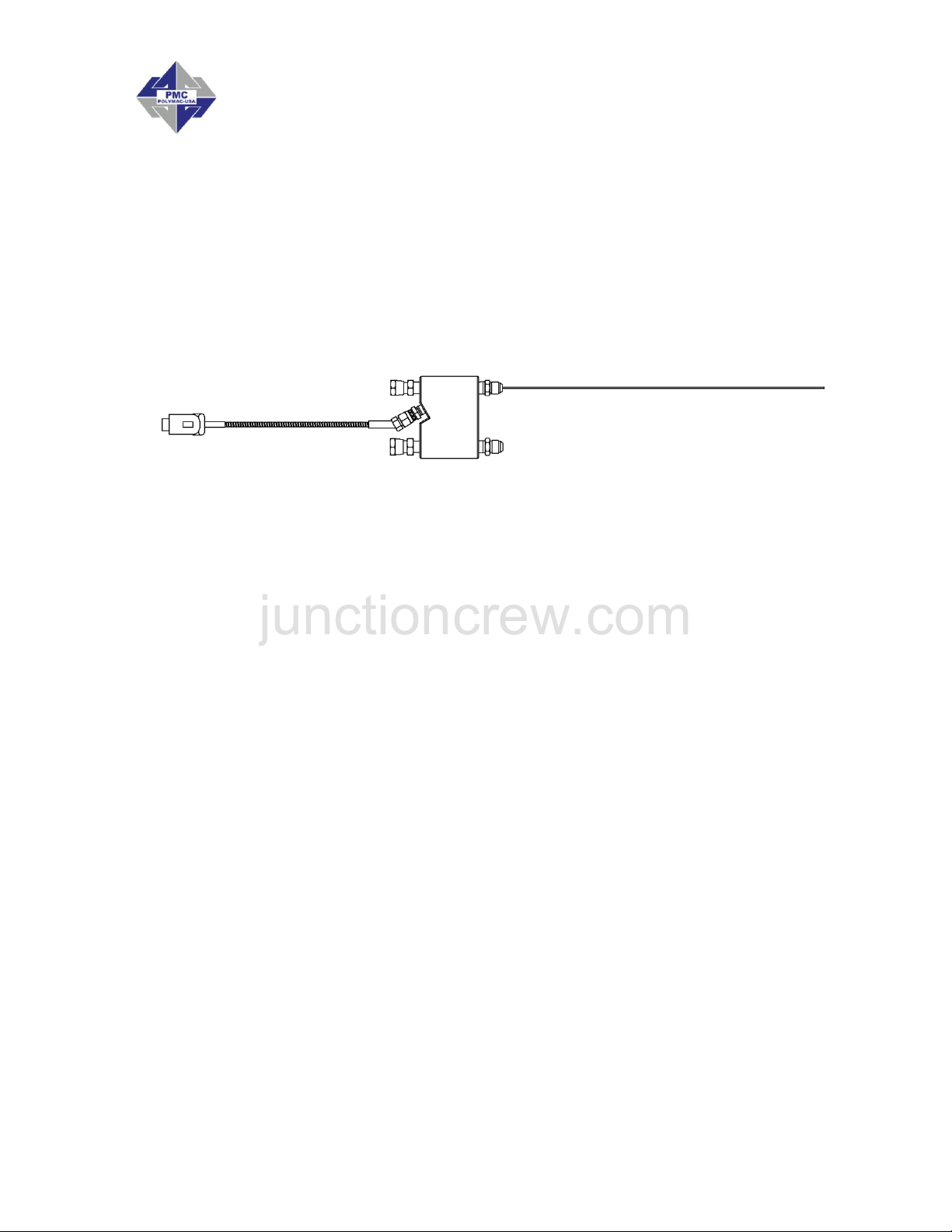
5. It is recommended the TSU be installed between the last section of Heated Hose and
the Gun Whip. Carefully straighten the sensing wire, inserting it in the Iso (A) Heated
Hose and tighten fluid fittings with appropriate sized open-end wrenches.
CAUTION! To protect the TSU sensor, you must pay special attention not to
kink or excessively bend the Heated Hoses. Do not coil the Heated Hoses
with a diameter of less than 4 feet (1.22 Meters).
Temperature Sensing Unit
(TSU) Part # EL-51A
Replacement Sensor Part # EL-51A-2
CAUTION! Connecting the TSU between the first and second section of
Heated Hose results in the TSU sensing the material temperature exiting the
Heater and not the inside of the Heated Hose near the Spray Gun.
21
Page 22
PH/PHX-2 Manual
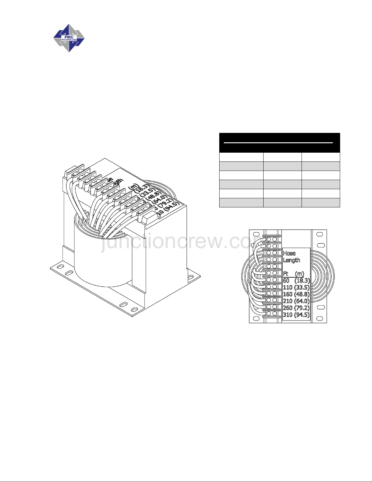
HOSE TAP TO LENGTH CHART*
Tap
Feet
Meters
90v
310
94.5
75v
260
79.5
60v
210
64.0
45v
160
48.8
30v
110
33.5
18v
60
18.3
junctioncrew.com
6. Hose Heat Transformer
The Hose Heat Transformer offers the ability of connecting to different output voltages
depending on the total length of the Heated Hose in use, maximizing the heating ability of
the Heated Hose. The factory setting is 18 volts for use with 60 feet of Heated Hose.
Before starting the Proportioner, ensure the setting matches the Heated Hose length
installed. If Heated Hose sections are added or removed, the Tap setting should be
changed to a setting which will limit the maximum amperage in the Heated Hose to 52
amps. The suggested settings are tabled below:
*Note: Only the 3KVA transformer is shown above. The 2 KVA and 5 KVA transformers
are also available. See page 10 for technical specifications.
6. Ensure the Manual Valves are CLOSED and connect the Coupling Block to the Heated
Gun Whip.
CAUTION! Excessive force closing or opening the Manual Valves may result
in damage to the Manual Valves and/or Coupling Block.
22
Page 23
PH/PHX-2 Manual
junctioncrew.com
7. Connect the Transfer Pump/ Heated Hose Assemblies/ Air Supply and Air Dryer
systems as required. Review the Installation Instructions for each to ensure proper setup and operation.
8. Install the Material Transfer Pumps as follows:
WARNING! If Transfer Pumps have been previously used, pay
special attention to connect each Pump to “its” specific material.
Inadvertently changing the Transfer Pumps will cause a
chemical reaction rendering them useless.
NOTE! Placing a tape of the same color as of the Material
Delivery Hoses (red for the Iso (A), blue for the Poly (R)) on
each Transfer Pump would be a good method for minimizing
errors in connection.
a. Make sure that the Inlet Valves on the Proportioner are closed.
b. Connect one end of the Polyol (R) Material Delivery Hose (¾”
thread) to the Proportioner Polyol (R) Inlet Valve and the other end
to the Polyol (R) Transfer Pump.
c. Connect one end of the Iso (A) Material Delivery Hose (½” thread) to
the Proportioner Iso (A) Inlet Valve and the other end to the Iso
Transfer Pump.
d. Connect the air hose to the Transfer Pumps after ensuring each
Transfer Pump Shut-Off Valve is CLOSED.
NOTE! To avoid errors in connection, the Coupling connections
of the Iso (A) and Poly (R) Material Delivery Hoses are different
sizes, making it difficult to swap connections.
e. Ground the Transfer Pump as recommend by the material supplier.
The movement of product inside the Hoses can cause static
electricity and produce electrical discharges.
f. Connect air to the air line coming off the first section of hose (90-110
psi, 6-8 bar)
23
Page 24

PH/PHX-2 Manual
junctioncrew.com
PROPORTIONER PURGING
WARNING! Use suitable Personal Protection Equipment (PPE) and follow
the recommendations in the Safety Information provided by product
suppliers when installing or working with the unit.
WARNING! Do not turn the Temperature Controllers ON until the
Proportioner purging procedure is complete and the Primary Heaters and
Heated Hoses are filled with material.
NOTE! Before using the Proportioner it is necessary to purge the entire
system, including Heated Hoses of mineral oil left over from Quality Control
testing and air. The following procedure is also followed to purge air
entrapped by running out of material in the supply Drum/Reservoirs resulting
in a significant indicated material pressure imbalance as indicated by the
Pressure Gauges and sprayed material.
1. Ensure the following before proceeding:
a. Air supply to Transfer Pumps is 90 - 110 psi (6 - 8 bar)
b. Proportioner Inlet ball Valves are CLOSED.
c. All connections are tight.
d. Material should be stored to the material suppliers' recommended temperatures.
e. Spray gun coupling block is installed and manual valves are closed.
2. Slowly OPEN the Poly (R) Transfer Pump Air Shut-Off Valve allowing Pump to cycle
slowly as it fills the Material Delivery Hose to the Proportioner. Check for leaks.
3. OPEN Poly (R) Coupling Block Manual Valve over a waste container.
4. Slowly OPEN Proportioner Poly (R) Inlet Valve allowing Transfer Pump to move material
through the system. When all spitting of air stops and all traces of mineral oil have
disappeared, CLOSE Poly (R) Coupling Block Manual Valve. Clean Coupling Block.
5. Repeat steps 2 to 4 for Iso (A) side.
CAUTION! Properly dispose of all waste chemicals in accordance with all
applicable local, state and federal codes. DO NOT turn on the Auto
Countdown Switch or the Pressure Balance Control Switch.
6. Turn Hydraulic Pressure Control (L, page 14) full COUNTERCLOCKWISE.
7. Turn ON Main Power (N, page 15). Green pilot will light.
8. Turn ON Control Power (R15, page 15). Switch will light.
9. Turn ON Motor Power (X, page 16). Switch will light.
10. Set Pump Switch (P, page 15) to NORMAL. Turn Hydraulic Pressure Control
CLOCKWISE increasing material pressure to 400 psi (28 bar). Both Material Pressure
24
Page 25

PH/PHX-2 Manual
junctioncrew.com
Gauges (E, F, page 14) should approximately read the same. Check all Heated Hose
Coupling connections for leakage.
11. Check all TSU and “Fast-Lock” connections for leaks.
12. Bundle all Heated Hose Connections ensuring that there are NO kinks in the TSU
Cable or Air Hose. Wrap with Electrical Tape to securely hold all components in place
and minimize places for bundle to snag onto job site protrusions.
25
Page 26

PH/PHX-2 Manual
junctioncrew.com
PRESSURE BALANCE CONTROL
The PH Series Proportioner has been designed with a pressure balance control system. This
system will give the operator of this machine the ability to control a pressure imbalance within
certain predetermined parameters.
The system consists of:
Selector Switch
Fault Light
On Light
Control Unit
Pressure Transducers
Relay
Operation
Position the selector switch on one of the three options:
Pressure differential number – these consist of 300, 400, 500, 600, and 700 PSI.
Selecting any of these numbers with the switch will activate the green ON light. While
the pressure differential numbers are selected, the control box will continually monitor
pressure on both sides of the Proportioner. In the event that the pressure differential
between both sides of the Proportioner is equal to or larger than the selected number,
a fault is given (the red fault light is turned on and the active green light is turned off)
and shuts down.
Off – if the selector switch is placed in this position, the Proportioner will operate as
though there is NO PRESSURE BALANCE CONTROL SYSTEM (neither the red fault
light nor the active green light will be lit). The over pressure system will remain active
for the machine and personnel protection.
Reset – in the event of a pressure imbalance, resolve the Proportioner imbalance,
position the selector switch on reset to clear the fault light and restore power to the
Proportioner. After the fault has been cleared, position the switch in either a Pressure
Differential number or in the Off Position to continue operations.
26
Page 27
PH/PHX-2 Manual
junctioncrew.com
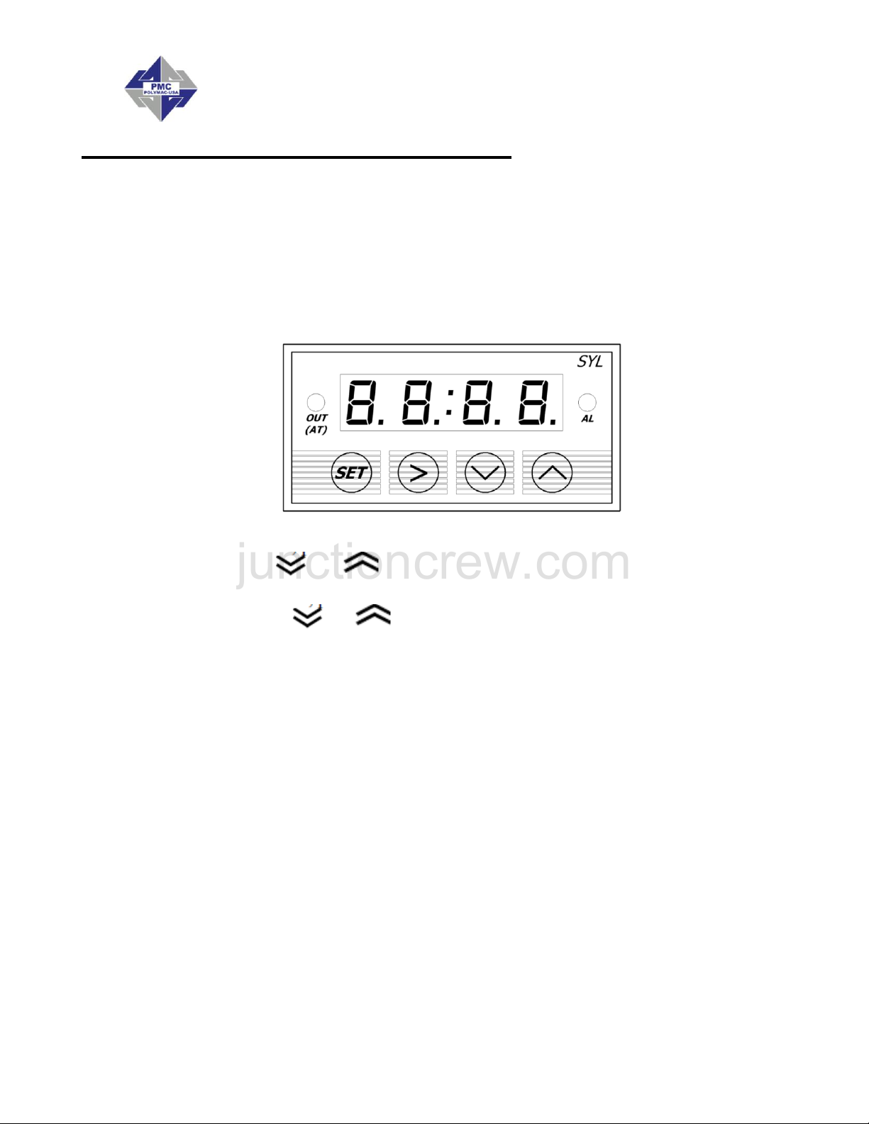
DIGITAL TEMPERATURE CONTROLLER
The PH Series has three (3) Digital Temperature Controllers to manage the temperatures
for the Primary Heaters and the Heated Hose. The Hose Heater Controller is
programmed differently from the heater Controllers and therefore not interchangeable with
them.
WARNING! Do not turn the Temperature Controllers ON until the
Proportioner Purging procedure is complete and the Primary Heaters
and Heated Hoses are filled with material.
1. Ensure Main Power (N, page 15) and Control Power (R, page 15) is ON.
2. Press and release or button. The display will flash and indicate its current
set point.
3. Press and hold the or to increase or decrease the material temperature
set-point to the desired value as determined by the material supplier or application
conditions.
4. Once the set point is entered the controller will go back to ambient temperature on its
own.(5-8 seconds)
WARNING! The Controllers are factory programmed and are not field re-
programmable. If a problem is encountered, contact your authorized
distributor. Do not attempt to change any of the programmed parameters. Do
not substitute a Controller from an alternate supplier as its use may result in
equipment damage and/or bodily injury.
NOTE! The Temperature Controller normally displays the actual material
temperature. When lit, the red “OUT” display in the upper left indicates power
is being sent to the Heater. The “OUT” display goes out when the material
temperature has reached its set-point. The “OUT” display will continue to
cycle on and off indicating the Controller is maintaining the material
temperature set-point.
27
Page 28

PH/PHX-2 Manual
junctioncrew.com
START-UP
NOTE! Follow the recommended procedure in the order shown.
CAUTION! The Start-up procedures assume that all steps in Proportioner
purging have been performed and no problems were found.
1. Check the hydraulic fluid level and service as required.
2. Make sure the materials have been stored at the manufacturer's recommended
temperature. Ask your material supplier for information (Material Safety Data Sheet) on
the minimum storage temperature.
3. Y-Strainer screens should be checked routinely.
4. Connect air supply to the two Transfer Pumps and ensure Air Valves are in the full
OPEN position. OPEN both Proportioner Material Inlet Ball Valves.
CAUTION! Remove all Heated Hose sections from coiled storage and lay flat
to eliminate heat build-up and possible Heated Hose failure.
5. Turn ON Main Power (N, page 15).
6. Turn ON Control Power (R, page 15).
7. Turn ON Hose Heater (S, page 15) and confirm material set-point temperature as
recommended by the material supplier or application conditions.
CAUTION! To avoid excessive pressure in the Proportioner, wait for the Hose
Heater to reach its set-point temperature before continuing.
8. Turn ON each Primary Heater and confirm material set-point temperature as required by
the material supplier or application conditions has been reached.
9. Turn ON Motor Power (X, page 16).
10. Set Pump Switch (P, page 15) to NORMAL. One of the Directional Indicator Lights (Q,
page 15) will illuminate, indicating the Metering Pump direction, and the Metering Pump
Shafts will begin to move.
NOTE!
a. The Material Pressure Gauges (E, F, page 14) should be approximately equal and
remain constant throughout Metering Pump cycle. If not, refer to Trouble Shooting
section.
b. Directional Indicator Lights must indicate Metering Pump direction when Pump
Switch is in the NORMAL position. If not, refer to Trouble Shooting section.
11. Using the Hydraulic Pressure Control, adjust to the required stall pressure and check
each Material Pressure Gauge.
Stall pressure: When materials are at recommend application temperature and Metering
Pumps are pressurized but not moving.
28
Page 29

PH/PHX-2 Manual
MODEL
CYCLES PER GALLON
PH-2, 2000 PSI
123 pumps 23 cycles = 1 gallon
PHX-2, 3000 PSI
61 pumps 47 cycles = 1 gallon
junctioncrew.com
12. AUTO SHUT DOWN COUNTER
If this function is not needed, leave it in the off position.
To set the Auto Shut Down Counter:
a. Turn the switch to the on position, the green light will illuminate.
b. Insert the number of cycles desired to disable the PH machine by pushing in on the
white triangles to set the cycle count. Push in on the red button until the data is
replicated on the top row, the top row will count down. Figure B
c. When the counter counts down to zero the machine will stop and the pump
directional light will be off, push in on the red button to reset.
13. Proceed with Installation and Start-up of the Spray Gun as per the Gun manual.
29
Page 30

PH/PHX-2 Manual
junctioncrew.com
SHUT-DOWN
TEMPORARY
Follow the recommended procedure in the indicated order for Proportioner temporary shutdown such as lunch breaks.
1. Set Pump Switch (P, page 15) to OFF position.
2. Turn both “A” and “R” Heaters OFF. Hose Heater should remain ON. Never leave
Proportioner ON if unattended.
3. CLOSE Spray Gun Manual Valves.
CAUTION! Excessive force opening or closing the Manual Valves may result
in damage to the Manual Valves and/or Coupling Block.
LONG-TERM
Follow the recommended procedure in the indicated order for Proportioner shut-down when
work is stopped for the day.
1. Set the Pump Switch (P, page 15) to RETRACT.
2. Spray off the application surface until Material Pressure Gauges (E, F, page 14)
readings begin to fall.
CAUTION! To avoid possible Proportioning Pump Seal weepage, and
moisture vapor drive into the Heated Hoses, the system pressure should not
be reduced to zero. It is recommended to lower the system pressure to a
minimum of 400 psi (28 bar).
3. CLOSE the Spray Gun Coupling Block Manual Valves.
CAUTION! Excessive force opening or closing the Manual Valves may result
in damage to the Manual Valves and/or Coupling Block.
4. Turn OFF Motor Power (X, page 16).
5. Turn OFF the A and R Heaters and Hose Heater (S, page 15).
6. Turn OFF the Control Power (R, page 15).
7. Turn OFF the Auto Shut Down Switch (V, page 16).
8. Turn OFF the Main Power (N, page 15).
9. Disconnect the air supply to the two Transfer Pumps and CLOSE the Proportioner
Material Inlet Valves.
30
Page 31

PH/PHX-2 Manual
junctioncrew.com
TROUBLESHOOTING
This PH Series Proportioner has been designed and built to withstand severe working
conditions with a high degree of reliability, provided that it is used in a suitable application by
a properly trained operator. This chapter contains information on possible faults that may
interrupt the operation of the PH Series Proportioner. The information provided will serve as a
guideline to detect and resolve problems. In any case, feel free to contact your authorized
PMC distributor, where a qualified technician will advise you.
WARNING: Only qualified personnel should perform troubleshooting;
unqualified personnel may cause damage to the unit and put the operator
at risk.
To prevent possible injury caused by incorrect handling of the
raw materials and solvents used in the process, carefully read
the safety data sheet provided by your supplier.
Deal with the waste caused according to current regulations.
To avoid damage caused by the impact of pressurized fluids,
do not open any connection or perform maintenance work on
components subject to pressure until the pressure has been
completely eliminated.
Use suitable protection when operating, maintaining or being
present in the area where the equipment is functioning. This
includes, but is not limited to, the use of protective goggles,
gloves, shoes and safety clothing and breathing equipment.
The equipment includes components that reach high
temperatures and can cause burns. Hot parts of the equipment
must not be handled or touched until they have cooled
completely.
To prevent serious injury through crushing or amputation, do
not work with the equipment without the safety guards installed
on the moving parts. Make sure that all the safety guards are
correctly reinstalled at the end of the repair or maintenance
work of the equipment.
31
Page 32

PH/PHX-2 Manual
junctioncrew.com
Heaters
WARNING! Only qualified personnel should perform troubleshooting;
unqualified personnel may cause damage to the unit, personnel, or
property and put the operator at risk. The Heaters are components that
reach high temperatures; you must wait until they cool before handling.
NOTE ! The Thermal Limit Switch is a safety switch in contact with the Heater
Body. If the surface temperature exceeds 220 F (109 C) the Limit Switch will
shut off the Heater power. The Limit Switch will not re-set until the
temperature in the Heater is below 190 F(88 C). The system is designed that
in case of an over temperature, a contactor located in the console will open
and disable power to both Heaters and the Hose.
Follow the recommended procedure in the indicated order to solve the problem and
avoid unnecessary repairs. Make sure all Switches are in the correct position and
Indicator Lights ON before determining the existence of a fault.
32
Page 33

PH/PHX-2 Manual
junctioncrew.com
PROBLEM______________________________________________________________
Primary heater does not heat and the display on the controller shows ambient temperature.
SOLUTIONS
1. Check that the light on the on/off switch is lit when the heater is turned on, if not
replace the switch.
If the light is on, move to the next step.
2. Check the heater breaker in the main console and reset the breaker. If it continues to
trip, wrap an Amp Clamp around one of the wires coming off the breaker. If the
Amperage reading does not exceed the rating of the breaker, the breaker needs to be
replaced. If the breaker draws more than its rating the most likely cause is that one or
more of the fire rods located in the heater are shorted.
If the breaker is not tripped, move on to the next step.
3. Open the console top and locate the solid state relays for the heaters, looking over
the console top from the front of the machine. There are two relays to the left bottom
of the console, the one to the far left is for the “A” heater and the one to the right is for
the “R” heater. With the heater on, look to see if an LED light is lit on the relay.
If there is no LED light on the solid state relay, move to the next step.
4. With a DC volt meter read across position A1 and A2 on the solid state relay (smaller
wires) if you have a reading of 4-6 volts DC and the AC reading across L1 and L2
(Heavy wires) reads 208-230 volts AC replace the solid state relay. With 4-6 volts DC
at A1 and A2 the proper reading should be 1 volt AC across L1 and L2. A defective
over temperature switch will open a contactor disabling both Heaters and the Hose.
If there is no DC voltage to the relay, move to the next step.
5. Check the M1 contactor to ensure it is activated. If not, inspect the contactor for
failure.
If the M1 contactor is activated, move to the next step.
6. Using a DC volt meter measure across position 9 and 10 on the back of the heater
controller. This is the output of the controller and sends power to the solid state relay;
your reading will be 4-6 volts DC. If there is no reading check to make sure that the set
temperature of the controller is above the actual temperature reading on the controller.
Before replacing the controller read across position 1 and 2 to make sure that the
controller is powered up, your reading will be 208 to 230 volts AC. If there is no voltage
detected; check for loose wires or a malfunction of the heater circuit breaker.
33
Page 34

PH/PHX-2 Manual
INDIVIDUAL OHMS MEASUREMENT
1250 WATT
37 OHMS
1500 WATT
31 OHMS
1750 WATT
27 OHMS
junctioncrew.com
PROBLEM________________________________________________________________
Primary heater does not heat and the display on the controller shows an error message
(SbEr, EEPE, CjEr, AdEr).
SOLUTIONS
1. Check position 6 and 7 on the heater controller for loose wires.
If the wires are tight move to the next step.
2. Remove the heater cover and check that the thermocouple wires are secure to the
harness going up to the controller.
If there are no loose connections replace the heater thermocouple.
PROBLEM______________________________________________________________
Primary heater controller shows excessive temperature and the circuit has turned off.
CAUTION! The heater must be allowed to cool down before continuing.
SOLUTIONS
1. Set the controller set point at least 20 degrees lower than the temperature shown on
the controller. Briefly turn on the heater and look for the LED light on the solid state
relay to be on.
If the light is on replace the controller.
If the light is off replace the solid state relay.
PROBLEM_________________________________________________________________
Primary heater Temperature drops excessively while spraying.
SOLUTIONS
1. Temperature of the chemical in the containers is too cold.
2. Exceeding the flow rate specification of the machine. Use a smaller mixing chamber
to reduce flow.
3. Disconnect power to the machine. One or more of the fire rods in the heater have
malfunctioned. Remove the heater cover and disconnect the wires to measure the
resistance across each rod. Installing a smaller mixing chamber in the gun may allow
you to spray until a new rod(s) is installed.
CAUTION! If the rod that is used in conjunction with the thermocouple is
defective do not operate the heater until the rod is replaced.
34
Page 35

PH/PHX-2 Manual
junctioncrew.com
Hydraulic Drive System
Follow the recommended procedure in the indicated order to solve the problem and
avoid unnecessary repairs. Make sure all Switches are in the correct position and
Indicator Lights ON before determining the existence of a fault.
WARNING! Before correcting any kind of defect, make sure the Main Power
Switch is OFF and incoming power is locked OFF. NEVER access the inside of
the Control Panel with the Proportioner power supply ON. The Hydraulic Unit is
a component that works under pressure. Do not open any connection or carry
out maintenance on components subject to pressure until all pressure has been
bled to zero.
CAUTION! Do not attempt to reset the Motor Contactor more than twice.
Failure of the Motor Contactor safety mechanism will occur and the Contactor
will become inoperable and/or the Motor will be damaged. The cause of the
problem must be determined and corrected.
PROBLEM_________________________________________________________________
Hydraulic Pump does not develop pressure and the electric
motor is not running.
SOLUTIONS
1. Motor Contactor Safety or Motor Breaker
The Electric Motor is protected from excessive current
by an Overload Safety Switch. After allowing the
Motor to cool, open the Control Panel and reset Motor
Contactor Safety.
35
Page 36

PH/PHX-2 Manual
junctioncrew.com
PROBLEM_________________________________________________________________
Hydraulic Pump does not develop pressure.
SOLUTIONS
1. Hydraulic Power Package
NOTE! Hydraulic pressure is not generated if the Motor Power Switch (X,
page 12) is OFF or the Pump Switch (Y, page 12) is in the OFF position.
With the Pump Switch in the NORMAL position, the failure of the Hydraulic Pump to
develop pressure is loss of pump suction (prime). To ensure positive prime, check the
following:
a) Motor rotation (page 19).
b) Hydraulic Reservoir is filled to the correct level (page18).
c) Hydraulic Pump Case is filled with the proper hydraulic fluid (page 51).
d) Loose Inlet Plumbing: Check that all inlet plumbing to Hydraulic Pump is
tight ensuring no air leakage into the hydraulic system.
PROBLEM______________________________________________________________
Low or zero hydraulic pressure with unusual Hydraulic Pump noises.
SOLUTIONS
1. The use of an incorrect hydraulic fluid can result is unusual noises from the pump,
excessive wear, and moisture absorption. Ensure the hydraulic oil used is from the list
on page 51. In addition, continuous excessive hydraulic oil temperature as well as
failure to change the hydraulic oil on a yearly basis will cause the oil to fail and result in
excessive Hydraulic Pump wear and unusual noises.
2. Loose Inlet Plumbing: Check that all inlet plumbing to Hydraulic Pump is tight,
ensuring no air leakage into the hydraulic system.
36
Page 37

PH/PHX-2 Manual
junctioncrew.com
Metering Pump Line
NOTE: As seen from front of unit.
Follow the recommended procedure in the indicated order to solve the problem and
avoid unnecessary repairs. Make sure all Switches are in the correct position and
Indicator Lights ON before determining the existence of a fault.
PROBLEM ____________________________________________________________
Metering pumps do not change direction and the pressures on both of chemical gauges are
lower than normal.
SOLUTIONS
1. The Metering Pump Line has Reversing Plates which actuates two Proximity Switches
(EL-153, Page 82), one at each end of the stroke. The Prox Switches in turn actuates
the appropriate Directional Valve Solenoid (HI-05003, Page 82).
Failure to make contact with either PROX Switch may be caused by:
Deformation of the Reversing Plate.
Foreign material preventing the Reversing Plate from contacting the Prox
Switches.
2. Passing of the Reversing Plate beyond the Prox Switch may be caused by:
Failure of the Prox Switch and related components on the side of the over-run.
Failure of a component of the Directional Valve.
Mounting Plate (PU-07006, Page 82) and/or Prox Switch is out of adjustment.
IF THE DIRECTIONAL INDICATOR LIGHT (P, Q, Page 15) IS ON CHECK THE
REVERSING VALVE COIL ON THE SIDE THAT THE LIGHT IS ON. IF YOU HAVE 24
VOLTS DC AT THE PLUG CHECK THE OHM’S RESISTANCE OF THE COIL, IT SHOULD
READ APPROXIMATELY 19 OHM’s, IF NOT REPLACE THE COIL OR REVERSING
VALVE.
37
Page 38

PH/PHX-2 Manual
junctioncrew.com
IF THE DIRECTIONAL INDICATOR LIGHT IS OFF PROCEED BELOW
BEFORE TROUBLESHOOTING, THE REVERSING PLATE MUST BE MOVED AWAY
FROM THE SWITCH.
a) Bleed down the chemical pressures.
b) Ensure Pump Switch (X, page 16) is OFF.
c) Turn on the motor (W, page 16).
d) Go to the Directional Valve and locate the Actuation Coils. Located in the middle of
each coil is small round tab that can be pushed in to manually shift the spool to
move the pumps. If the Reversing plate is all the way to the left push in on the right
side coil. If it’s all the way to the right side, push in on the left side coil.
WARNING! THE MOTOR MUST BE OFF AND THE PUMP SWITCH IN THE NORMAL
POSITION.
Take a small screw driver or a thin piece of metal and move it across the front of each
Prox switch. A red light on the back of the switch should illuminate. If not, replace the
switch that does not light.
If the Prox switches light up, turn off all power and check for continuity on both over
pressure switches, pin 1 and 2. If the pressure switches are good, go to the two solid state
relays inside the console and interchange them, they can be pulled from their housing.
Power up the unit with the pump switch in the normal position and the motor OFF. If the
directional light comes on replace the defective solid state relay. If not replace the
Latching relay.
38
Page 39

PH/PHX-2 Manual
MATERIAL CONDITION
“A” GAUGE
“R” GAUGE
NORMAL
LACK OF ISO (A)
LACK OF POLY (R)
RESTRICTION OF ISO (A)
RESTRICTION OF POLY (R)
junctioncrew.com
3. Safety Pressure Switch
Each Metering Pump has a Safety Pressure Switch set to 2,200 psi. for #123 pumps,
3,200 psi for #61 pumps. When the material system reaches this pressure, the Safety
Pressure Switch will remove power from the Directional Valve and Direction Indicator
Lights (Q, page 15). Lack of Direction Indicator Lights along with high pressure indicated
on one or both of the material Pressure Gauges (E, F, page 14) is an indication of an
over-pressure condition. The Safety Pressure Switches are a momentary design; when
the pressure bleeds off the Metering Pump Line will resume normal operation. However,
the cause of the over-pressure should be determined and corrected. The three most
common causes are:
a) Cavitations of the Metering Pump on the low pressure side causing high pressure
on the opposite side.
b) A restriction in the Spray Gun on the high pressure side.
4. Pressure/Material Imbalance
In summary troubleshooting this problem requires the applicator to:
a) Know what the NORMAL spray pressures are for the application in progress.
b) Determine what material is NOT exiting the Mixing Chamber.
c) Read the Pressure Gauge on the problem side and interpret the reading.
39
Page 40

PH/PHX-2 Manual
Directional
Indicator Light ON
Directional
Indicator Light ON
Iso Pressure Gauge
FALLS
Iso Inlet Ball does not seat
properly
Iso Discharge Ball does not
seat properly
Poly Pressure Gauge
FALLS
Poly Discharge Ball does
not seat properly
Poly Inlet Ball does not
seat properly
junctioncrew.com
5. Cavitations
Cavitations occur when the Metering Pump (B or C, page 14) requires a larger volume of
material than the supply system (Transfer Pump) can furnish. This creates a "void" of
material in the Metering Pump. The most common causes of cavitations are:
a) Material temperature too low causing increased material viscosity resulting in the
inability of the Transfer Pump to maintain sufficient supply to the Metering Pump.
This is most common with today's blowing agents. Ensure the material
temperature in the drums is no lower than the material suppliers' recommendation.
b) Failure to vent the material drum while drawing material out with the Transfer Pump
causes a vacuum and cavitations in the Transfer Pump. Ensure the drum is vented
to the atmosphere or a Desiccated Air Dyer Kit is installed as recommended by the
material supplier.
c) Insufficient air volume for Transfer Pump or a partially closed Transfer Pump Air
Valve will limit the ability of the Transfer Pump to operate at its maximum
capability.
d) Inlet Material Screen (M, page 14) obstructed (See MAINTENANCE section,
page 46).
e) Metering Pump Inlet Ball does not seat properly allowing material to flow back into
the Material Delivery Hose when the Metering Pump is on the "Discharge" stroke.
This causes the volume of material on that Metering Pump to be less on the
discharge stroke resulting in intermittent off-ratio material and Pressure Gauge
fluctuation.
6. Pressure Loss: Discharge/Inlet Ball
Simultaneous observation of the material Pressure Gauge (E, F, page 14) and
Direction Indicator Light (Q, page 15) is necessary to determine which direction the
Metering Pump fails to maintain pressure. Refer to the chart to determine problem:
In most cases the cause of a leaking Inlet/Discharge Ball is foreign material preventing
the Ball from seating properly. If the above steps do not resolve the problem, replace
the appropriate Ball, Ball Seat.
For service see MAINTENANCE/Metering Pump Line, page 48.
40
Page 41

PH/PHX-2 Manual
junctioncrew.com
Hose Heating
WARNING! Before correcting any kind of defect, make sure the Main Power Switch is
OFF and incoming power is locked OFF. NEVER access the inside of the Control Panel
with the Proportioner power supply ON. The Heated Hose are components which reach
high temperatures; you must wait until they have cooled before handling.
Follow the recommended procedure in the indicated order to solve the problem and
avoid unnecessary repairs. Make sure all Switches are in the correct position and
Indicator Lights ON before determining the existence of a fault.
CAUTION! All electrical testing must be done by a qualified electrician.
PROBLEM______________________________________________________________
Heated Hose does not heat and the display on the controller shows ambient temperature.
SOLUTIONS
1. Check that the light on the on/off switch is lit when the heater is turned on, if not
replace the switch.
If the light is on, move on to the next step.
2. Check the Hose Heat breaker in the main console and reset the breaker. If it
continues to trip, wrap an Amp Clamp around one of the wires coming off the
breaker. If it does not draw more than the rated value of the breaker, the breaker
needs to be replaced.
If the breaker is not tripped, move on to the next step.
3. Check the circuit breaker mounted on the transformer and reset the breaker. If it
continues to trip, wrap an Amp Clamp around one of the wires from the transformer
going to the heated hose. If it does not draw more than the rated value of the
breaker, the breaker needs to be replaced.
If the Amp Draw is less than the rated value, move on to the next step.
4. Check that the tap setting on the transformer is set for the proper hose length.
If it is set correctly move to the next step.
5. To check the secondary side of the transformer, you must take an AC volt reading
across the two leads coming out of the transformer that are connected to the “A”
and “R” hose leads. If you are reading voltage (your volt reading will vary
depending on what tap setting is used), most likely the problem is in the heated
hose. Either a connector has come loose or there is a broken wire.
6. Because the gun whip takes the most abuse, it is most likely the whip that has
failed. Disconnect the crossover wires on the machine end of the whip hose and
connect the two wires together coming off the 50’ section. Turn on the hose heat
41
Page 42

PH/PHX-2 Manual
junctioncrew.com
and see if the hose heat circuit is operating; if so replace the whip. To take a
continuity reading through the heated hose, one of the leads from the transformer
to the “A” or “R” heated hose must be disconnected.
If no voltage is coming out of the transformer to the heated hose move on to
the next step.
7. Open the right side of the tank (where the transformer is located) and locate the
solid state relay for the hose circuit (EL-35, Page 82). With the hose turned on and
the LED light illuminated on the relay, take a volt meter (set on DC) and measure
across position A1 and A2; your reading should be 24 volts. Then take an AC volts
measurement across position L1 and L2 (heavy wires). With the relay functioning
properly you should have a 1 volt Reading. If the Reading is 18 to 90 volts AC, the
relay has malfunctioned and needs to be replaced. If the AC Reading across L1
and L2 is .025 volts check the over temperature switches in the heaters. A
defective over temperature switch will open a contactor disabling both Heaters and
the Hose.
If there is no light on the solid state relay, move to the next step.
8. Using a DC volt meter, measure across position 5 and 6 on the back of the hose
controller. This is the output of the controller and sends power to the solid state
relay. Your reading will be 4-6 volts DC. If there is no voltage, check to make
sure that the set temperature of the controller is above ambient temperature.
Before replacing the controller, read across position 1 and 2 to make sure that the
controller is powered up; your reading will be 208 to 230 volts AC.
If there is no DC voltage to the relay, move to the next step.
PROBLEM______________________________________________________________
Hose does not heat and the display on the controller shows an error message (EEEE).
SOLUTIONS
1. Check position 6 and 7 on the heater controller for loose wires.
If the wires are tight, move to the next step.
2. Remove the transformer cover and check that the thermocouple wires are secure
to the harness going up to the controller. If there are no loose connections,
disconnect the wire from the TSU and connect it directly to the thermocouple
harness coming out of the hose transformer.
If the controller still shows the error code, replace the hose thermocouple. If
the error code goes away and temperature is now shown on the display of
the controller, then all the TSU harnesses from the TSU to the transformer
need to be checked for loose connectors or one or more of the harnesses are
defective.
42
Page 43

PH/PHX-2 Manual
junctioncrew.com
PROBLEM______________________________________________________________
Heated hose controller shows excessive temperature
SOLUTIONS
1. Set the controller set point at least 20 degrees lower than the temperature shown
on the controller. Briefly turn on the hose and look for the led light on the solid state
relay to be on.
If the light is on replace the controller.
If the light is off replace the solid state relay.
PROBLEM______________________________________________________________
Hose will heat but does not come up to set temperature.
SOLUTIONS
1. Check the tap setting on the transformer to ensure that the correct position has
been selected for the length of hose being used. Depending on the machines
incoming voltage, you may have to move the tap setting higher (up one).
CAUTION! Do not exceed the trip value of the transformer hose breaker.
WARNING! Before correcting any kind of defect, make sure the Main Power
Switch is OFF and incoming power is locked OFF. NEVER access the inside of
the Control Panel with the Proportioner power supply ON.
PROBLEM______________________________________________________________
Hose does not heat and the display on the controller shows an error message.
SOLUTIONS
1. Check position 9 and 10 on the heater controller for loose wires.
If the wires are tight move to the next step.
2. Remove the transformer cover and check that the thermocouple wires are secure
to the harness going up to the controller. If there are no loose connections
disconnect the wire from the TSU and connect it directly to the thermocouple
harness coming out of the hose transformer.
If the controller still shows the error code replace the hose thermocouple.
If the error code goes away and temperature is now shown on the display of
the controller, then all the TSU harnesses from the TSU to the transformer
need to be checked for loose connectors or one or more of the harnesses are
defective.
43
Page 44

PH/PHX-2 Manual
junctioncrew.com
Pressure Balance Control
If the Pressure Balance Control box is not working properly, follow these steps to resolve the
potential issue:
1. With the Main Power ON, check the Power/Run light on the Control Unit:
a. If OFF, the Control Unit is not getting power. Check for loose or poor wire
connections. If the Power/Run light still does not turn on, contact your
authorized PMC distributor.
b. If SOLID, the Control Unit has power but no program. Contact your authorized
PMC distributor.
c. If BLINKING, the Control Unit has power and is programmed properly.
Proceed to the next step.
2. With Main Power ON, turn the Rotary Switch to a Pressure Differential Number and
check the Amber light on CR1:
a. If OFF, CR1 is not activating properly. Check for loose or poor wire
connections between the Control Unit and CR1.
b. If ON, CR1 is activating, but the mechanical switch inside the relay may not be
functioning properly. If the system has faulted (i.e. a pressure imbalance exists,
the ON light turns off, and the FAULT light turns on), but the pumps do not shut
off, check for continuity between contacts 11 and 12 on CR1. If there is
continuity, contact your authorized PMC distributor. If there is discontinuity,
proceed to the next step.
3. With Main Power OFF:
a. Check all remaining wires to ensure secure and proper connections.
b. Check for continuity across the ON light terminals and the FAULT light
terminals. These light units are LEDs (light emitting diodes) which means that
only one direction has continuity (similar to a check valve). When checking for
continuity, make sure to use the correct terminals on the multimeter.
4. Contact your authorized PMC distributor for further assistance.
44
Page 45

PH/PHX-2 Manual
junctioncrew.com
MAINTENANCE
To achieve maximum output from the PH Series Proportioner, a daily or regular maintenance
schedule is required.
To prevent possible bodily harm caused by incorrect handling
of the raw materials and solvents used in the process, carefully
read the safety information provided by your supplier.
Deal with the waste created according to current regulations.
Disconnect the unit from the power supply before carrying out
any operation inside the electrical console.
The electrical maintenance of the machine must only be
performed by a qualified electrician.
To avoid damage caused by the impact of pressurized fluids,
do not open any connection or perform maintenance work on
components subject to pressure until the pressures have been
completely eliminated.
Use suitable protection when operating, maintaining or
remaining in the operating area of the unit. This includes, but
is not limited to, the use of masks, protective goggles, gloves,
shoes and safety clothing.
The unit includes components that reach temperature that are
liable to cause burns. The hot parts of the unit must not be
handled until they have cooled.
To prevent serious harm by crushing or loss of limbs, do not
work with the unit without the safety duly installed on all
moving parts. Make sure that all of the safety protections are
correctly fitted after all repair or maintenance work.
CAUTION! All repairs performed by unqualified personnel or the use of parts
other than supplied by PMC may cause damage to the unit and put the operator
at risk.
45
Page 46

PH/PHX-2 Manual
junctioncrew.com
Inlet Material Screens
Inspection of the Inlet Material Screens on a daily basis is no longer necessary as long as
the following conditions are met.
1. Material drums are stored within the recommended material storage temperature
range and drums are not opened prior to installing the Proportioner Material Transfer
Pumps.
2. Desiccant air dryers are used to dry replacement air as material is removed from the
drums to the Proportioner.
3. Consolidation of old material into a common drum for use is minimized, especially the
Iso (A).
If the above conditions are met, inspection of the Inlet Material Screens may be done on a
bi-weekly basis.
NOTE! Inspect and clean Inlet Material Screens before Proportioner start-up.
They should not be cleaned after the days’ operation as the Proportioner
should be purged (see page 24) immediately after inspection and cleaning.
This is to reduce the risk of moisture contamination, contamination through
the reaction with the solvent used in the cleaning operation, and cross-over
at the Spray Gun due to air entrapment.
To check the Inlet Material Screens, proceed as follows:
CAUTION! Make sure the Main Power Switch is OFF and incoming power is
locked OFF.
1. CLOSE the Poly (R) Proportioner Inlet Valve.
2. Place a suitable container under the Material Inlet Strainer to collect the residual
material. Carefully loosen the Strainer
Screw allowing the material to drain into
the container.
3. Completely unscrew the Strainer Screw.
4. Remove the Seal, Spring, and Screen and
clean them with a suitable solvent. Dry the
parts and ensure the Screen is not
obstructed. Replace or clean the Screen if
more than 20% of the Screen surface is
obstructed by residue.
5. Reinstall the Screen, Spring, and Seal.
Screw on the Strainer Screw and screw in Strainer Screw.
6. OPEN the Poly (R) Proportioner Inlet Valve, pressurize the Material Transfer Pump,
check for leaks, and wipe Y-strainer clean.
7. Repeat above for the Iso (A) side.
8. Proceed with Proportioner Purging operation (page 24).
46
Page 47

PH/PHX-2 Manual
junctioncrew.com
Hydraulic Drive System
WARNING! Before performing any maintenance, make sure the Main
Power Switch is OFF and incoming power is locked OFF. The Hydraulic
Unit is a component that works under pressure. Do not open any
connection or carry out maintenance on components subject to pressure
until all pressure has been bled to zero.
The hydraulic unit should be serviced yearly:
1. Completely drain the Tank of hydraulic fluid.
2. Clean the Tank Top to prevent foreign material from falling into the Tank when the
Cover is removed.
3. Unscrew the Suction Pipe from its connection with the Hydraulic Pump.
4. Remove the Cover and Suction Pipe from the Hydraulic Tank. Take care not to
damage Tank Cover Gasket.
5. Inspect the bottom of the Tank for sediment and clean as required. Clean the Suction
Pipe and its connections
6. Fill the Tank with 12 gal (45 L) of approved hydraulic fluid. See page 51 for
recommendations.
7. Insert the Suction Pipe into the Tank Cover and install the Cover. Again, take care not
to damage Tank Cover Gasket. Connect the Suction Pipe securely to the Hydraulic
Pump.
8. Ensure the Hydraulic Pump Case is full of fluid and proceed with the normal operation.
47
Page 48

PH/PHX-2 Manual
junctioncrew.com
Metering Pump Line
WARNING! Before performing any maintenance, make sure the Main Power
Switch is OFF and incoming power is locked OFF. Allow material temperature
to cool below 80F and bleed all material pressure to zero.
Weekly: When the Proportioning Pumps are functioning properly it is
not unusual for a small amount of Poly (R) material to appear on the
Pump Shaft. This material should be wiped away so dirt does not
accumulate on the Pump Shaft and the Pump Shaft Packings are not
damaged.
Yearly or as required: It is not unusual for those who use the PH Series Proportioner on a
regular basis to rebuild the Proportioning Pumps on a yearly basis and service the
Hydraulic Drive System (page 47) at the same time, while the Proportioner is out of service.
Pump Seal Replacement
Refer to Parts Identification (Pages 61-68) reference.
NOTE!
When Iso (A) Proportioning Pump Cylinder is disassembled for service, all parts
included in the Seal Kit (KT-PAX or KT-PA) should be replaced.
When the Poly (R) Proportioning Pump Cylinder is disassembled for service, all parts
included in the Seal Kit (KT-PAX or KT-PA) should be replaced.
When assembling Proportioning Pump, lubricate all Seals, Piston Rod, and Pump
Cylinder with #1 Lithium Grease to assist in assembly and minimize Seal damage
during re-assembly.
CAUTION! Use wooden or plastic tools or a brass brush for cleaning. Do not
use metal or abrasive tools that can scratch the contact surfaces.
48
Page 49

PH/PHX-2 Manual
junctioncrew.com
Material Heater
WARNING! Before performing any maintenance, make sure the
Main Power Switch is OFF and incoming power is locked OFF.
NEVER access the inside of the Control Panel with the
Proportioner power supply ON. The Heaters are components
that reach high temperatures; you must wait until they have
cooled before handling and bleed all material pressure to
zero.
Thermocouple Replacement
NOTE! The Thermocouple is assembled into the
Connector Body with a Ferrule and Nut. Once
inserted into the Body and the Nut is tightened, the
Ferrule locks to the Thermocouple and does not allow
it to be relocated or moved. The location of the
Thermocouple is very important and must be done
correctly before tightening the Nut.
1. Unscrew the Nut that holds the defective Thermocouple
and remove from the Body. Disconnect Thermocouple
wiring located under the Top Cover of the Heater.
Remove Body and discard.
2. Install Heating Element and Spring if also removed.
3. Install Connector Body into Heater using an open-end
wrench and tighten to prevent leakage. Teflon Tape or
appropriate Thread Sealant should be used.
4. Slide the Nut and the Ferrule over the Thermocouple and
insert this assembly into the Connector Body until it
comes into positive physical contact with the Heating
Rod. Make sure the Spring does not prevent the
Thermocouple from making contact with the Heating Rod.
5. Slowly tighten the Nut using an open-end
wrench, ensuring the Thermocouple
maintains positive physical contact with
the Heating Rod.
6. Reinstall the Thermocouple wires.
49
Page 50

PH/PHX-2 Manual
HEATING
ROD
INDIVIDUAL OHMS
MEASUREMENT
TOTAL OHMS MEASURMENT
PER FLUID SIDE
1250 WATT
39.0 Ω
13.0 Ω
1500 WATT
32.4 Ω
10.8 Ω
1750 WATT
27.5 Ω
9.2 Ω
junctioncrew.com
WARNING! Before performing any maintenance, make
sure the Main Power Switch is OFF and incoming power is
locked OFF. NEVER access the inside of the Control Panel
with the Proportioner power supply ON. The Heaters are
components that reach high temperatures; you must wait
until they have cooled before handling and bleed all
material pressure to zero.
To replace a defect Heating Rod, proceed as follows:
1. Ensure Main Power Switch is OFF and incoming power is
locked OFF. Depressurize proportioner and remove the Cover
on Heater.
WARNING! If the Heating Rod to be replaced is the one in contact with
the Thermocouple, it is necessary to remove the Thermocouple first (see
page 49). Do not loosen or tighten Thermocouple Body.
2. Disconnect the suspect Heating Rod from the wire connections and test the
Heating Rod again for proper electrical resistance.
3. Unscrew the Heating Rod and remove from the Heater Block along with its Spring
and inspect; it must be smooth and shiny in appearance. If it is blackened or has
material adhered to it replace the Heating Rod, even if ohm reading is acceptable.
4. Apply Teflon Tape or appropriate Thread Sealant to the Heating Rod thread and
assemble Heating Rod and Spring into the Heater Block. Tighten securely to 110
ft/lbs (150 Nm)
5. If necessary carefully re-install Thermocouple ensuring positive physical contact
with the Heating Rod. Make sure the Spring does not prevent the Thermocouple
from making contact with the Heating Rod. Tighten Nut with open-end wrench.
6. Reconnect wire connections and replace Cover.
7. Ensure Heater is full of material prior to electrical testing.
50
Page 51

PH/PHX-2 Manual
junctioncrew.com
HYDRAULIC OIL SPECIFICATIONS
Recommended Hydraulic Oil Specification:
ISO/ASTM Viscosity Grade 32
Viscosity: 28.8 – 35.2 SSU@ 104 F
Rust and Oxidation Inhibited
Manufacturers:
Mobil DTE24 (Recommended)
Cook’s Albavis 8
Ashland-Valvoline AW15
Shell – Tellus 32(25)
Sun Oil- Sunvis 706
Chevron ISO32
American Oil & Supply – PQ Iso 32
Gulf Oil – Harmony 32AW (43AW)
Atlantic Richfield – Duro AWS-150
BP Oil – Energol HLP-C32
Exxon – Nuto H-32(44)
A. Margolis – T.I.P.100-15-7
Fiske Bros. – Lubriplate Hyd. #0
SW – Alemite Hydraulic HD#0
Texaco – Rando HD32 (HD A0)
White & Bagley – EP Hyd. 150
51
Page 52

PH/PHX-2 Manual
HYDRAULIC CYLINDER REBUILD KIT (KT-05200)
Part Number
Description
QTY
HI-05025-1
U-Cup
2
HI-05025-2
Back-up Ring, Piston
2
HI-05025-3
Wear Ring
1
HI-05025-4
Rod Wiper
2
HI-05025-5
Shaft Seal
2
HI-05025-6
Back-up Ring, Bushing
2
OR-00039A
O-ring
2
OR-00040A
O-ring
2
HEATER THERMOCOUPLE KIT (KT-05021)
Part Number
Description
QTY
HI-05020
Body, Nut, Ferrule
1
HI-05021
Thermocouple
1
PUMP REBUILD KITS
Part Number
Description
QTY
KT-PAX
PHX pump rebuild kit (3000 psi)
see page 52
1
KT-PA
PH pump rebuild kit (2000 psi)
see page 54
1
junctioncrew.com
REPLACEMENT KITS
52
Page 53

PH/PHX-2 Manual
junctioncrew.com
PARTS IDENTIFICATION
FRAME ASSEMBLY
53
Page 54

PH/PHX-2 Manual
FRAME ASSEMBLY
FR-10
ITEM
QTY
PART NUMBER
DESCRIPTION
1 1 HI-00014-04A
TANK TOP GASKET
2 1 HI-05317
3/8” JIC BULKHEAD UNION
3 1 HI-05306
TANK PUMP DRAIN TUBE
4 1 HI-05319
1/2” JIC BULKHEAD UNION
5 1 HI-05308
TANK DISCHARGE TUBE
6 1 EL-05230-03
RT ANGLE CONDUIT CONNNECTOR
7 1 MQ-01008A
LUBE BOTTLE BRACKET
8 1 HI-00001A
SIGHT GAUGE
9 2 EL-05233
GROMMET; REVERSING SWITCH
10 1 HI-00047A
HYDRAULIC FILL STRAINER; CAP M
11 1 HI-00002-A-1
MODIFIED GROMMET; 1”
12 4 FLOOR STOCK
HEX SHCS 3/8-16 X 2
13 8 FLOOR STOCK
1/4-20 X 3/4 HEX SOCKET BUTTON
HEAD CAP SCREW
14 2 FLOOR STOCK
#8-32 X 3/4 HEX SOCKET BUTTON
HEAD CAP SCREW
15 4 TN-05704
4” SWIVEL CASTER
junctioncrew.com
54
Page 55

PH/PHX-2 Manual
HYDRAULIC MANIFOLD ASSEMBLY
HI-05335
ITEM
QTY
PART NUMBER
DESCRIPTION
1 1 HI-05070-3
HYDRAULIC MANIFOLD
2 2 HI-05007
6 ORB X 6 JIC
3 1 HI-05324
6 ORB X ½ JIC; 90 DEG
4 1 HI-05348
6 ORB EXTENTION
5 1 HI-05350
6 JIC 6 ORB "T"
6 1 HI-05040
PRESSURE GAUGE 0-2000 PSI
7 1 HI-05006-6
1/4 NPT X 6 JIC GAUGE FITTING
8 1 HI-05349
6 JIC X 8 JIC
junctioncrew.com
HYDRAULIC MANIFOLD ASSEMBLY
55
Page 56

PH/PHX-2 Manual
EXIT MANIFOLD ASSEMBLY
HI-05331 – LOW PRESSURE
HI-05343 – HIGH PRESSURE
ITEM
QTY
PART NUMBER
DESCRIPTION
1 1 HI-05307
OUTLET MANIFOLD
2 1 HI-05011
6 ORB X 6 JIC N
3 2 HI-05036
1/4 NPT FLUSH SEAL PIPE PLUG
4 1 HI-05329
6 ORB X 5 JIC
5 2 EL-195
TRANSDUCER 0-5000 PSI
6
2
HI-05028
PRESSURE GAUGE 0-3000 PSI (HI-05331)
2
HI-00035
PRESSURE GAUGE 0-5000 PSI (HI-05343)
7 2 HI-05318
6 ORB X 6 JIC; 45 DEG
8 2 HI-05323
10 ORB PLUG
9 2 HI-05070-4
HEX SOCKET O-RING BOSS
Hose Configurations
Forward
Underside
junctioncrew.com
EXIT MANIFOLD ASSEMBLY
56
Page 57

PH/PHX-2 Manual
HYDRAULIC SEAL ASSEMBLY
ITEM
QTY
PART NUMBER
DESCRIPTION
1 1 HI-05025-13
BUSHING; ROD
2 1 HI-05025-4
ROD WIPER
3 1 HI-05025-5
SHAFT SEAL
4 1 HI-05025-6
BACK-UP RING; BUSHING
5 1 OR-00039A
O-RING #218 HYD CYLINDER ROD
junctioncrew.com
HYDRAULIC SEAL ASSEMBLY
57
Page 58

PH/PHX-2 Manual
HYDRAULIC PISTON ASSEMBLY
ITEM
QTY
PART NUMBER
DESCRIPTION
6 1 HI-05300
HYDRAULIC PISTON
7 1 HI-05025-3
WEAR RING
8 2 HI-05025-2
BACK UP RING; PISTON
9 2 HI-05025-1
U CUP
junctioncrew.com
HYDRAULIC PISTON ASSEMBLY
58
Page 59

PH/PHX-2 Manual
junctioncrew.com
HYDRAULIC CYLINDER ASSEMBLY
59
Page 60

PH/PHX-2 Manual
HYDRAULIC CYLINDER ASSEMBLY
HI-05336
ITEM
QTY
PART NUMBER
DESCRIPTION
1
1 - HYDRAULIC PISTON ASSEMBLY (SEE PAGE 58)
2 1 HI-05301
HYDRAULIC CYLINDER
3 2 HI-05200-3
PORT BLOCK; HYDRAULIC
4
2 - HYDRAULIC SEAL ASSEMBLY (SEE PAGE 56)
5 2 HI-05302
FEMALE CLEVIS
6 2 HI-05303
SWITCH PLATE
7 2 OR-00040A
O-RING #036 HYD CYLINDER
8 1 HI-05332
FLANGE RTAINER, “A” SIDE
9 1 HI-05333
FLANGE RETAINER, “R” SIDE
10 4 FLOOR STOCK
5/16 WASHER
11 4 FLOOR STOCK
#8-32 X 3/8 FLAT COUNTERSUNK SHCS
12 2 FLOOR STOCK
SPRING PIN; SLOTTED 1/8” DIA
13 4 HI-05337
5/16 LOCK WASHER
14 4 FLOOR STOCK
5/16-18 X 7 HEX BOLT
junctioncrew.com
60
Page 61

PH/PHX-2 Manual
A & R SINGLE PUMP ASSEMBLY
PA-044
ITEM
QTY
PART
NUMBER
DESCRIPTION
24
4
PA-057
CAP SCREW
OUTLET BODY
ASSEMBLY
1
-
SEE PAGE 62
PISTON
ASSEMBLY
1
-
SEE PAGE 63
INLET BODY
ASSEMBLY
1
-
SEE PAGE 64
junctioncrew.com
A & R SINGLE PUMP ASSEMBLY (16:1)
61
Page 62

PH/PHX-2 Manual
OUTLET BODY ASSEMBLY
PA-044
ITEM
QTY
PART
NUMBER
DESCRIPTION
8 1 PA-045
OUTLET BODY
18 2 PA-052
ROD SEAL
ASSEMBLY
19 1 PA-051
ROD BUSHING
20 1 PA-064
PACKING NUT
21 1 PA-065
SCRAPER SEAL
junctioncrew.com
PA-044 OUTLET BODY ASSEMBLY
62
Page 63

PH/PHX-2 Manual
PISTON ASSEMBLY
PA-044
ITEM
QTY
PART
NUMBER
DESCRIPTION
1 1 PA-047
PISTON
2 1 PA-062
FLUID ROD
3 1 PA-046
PISTON VALVE
4 1 OR-916
O-RING
5 1 PA-048
3/4" CHROME BALL
6 1 PA-049
SPRING
7 1 PA-050
SPRING RETAINER
junctioncrew.com
PA-044 PISTON ASSEMBLY
63
Page 64

PH/PHX-2 Manual
INLET BODY ASSEMBLY
PA-044
ITEM
QTY
PART
NUMBER
DESCRIPTION
9 1 PA-053
INLET BODY
10 1 PA-055
PISTON BUSHING
11 1 PA-054
PISTON SEAL ASSEMBLY
12 1 OR-035
O-RING
13 1 PA-060
BALL STOP
14 1 PA-061
FOOT VALVE SPRING
15 1 PA-059
1" BALL
16 1 OR-920
O-RING
17 1 PA-058
INLET VALVE
junctioncrew.com
PA-044 INLET BODY ASSEMBLY
64
Page 65

PH/PHX-2 Manual
A & R SINGLE PUMP ASSEMBLY
PAX-044
ITEM
QTY
PART
NUMBER
DESCRIPTION
24
4
PA-057
CAP SCREW
OUTLET
BODY
ASSEMBLY
1 - SEE PAGE 66
PISTON
ASSEMBLY
1 - SEE PAGE 67
INLET BODY
ASSEMBLY
1 - SEE PAGE 68
junctioncrew.com
A & R SINGLE PUMP ASSEMBLY (30:1)
65
Page 66

PH/PHX-2 Manual
OUTLET BODY ASSEMBLY
PAX-044
ITEM
QTY
PART
NUMBER
DESCRIPTION
8 1 PAX-045
OUTLET BODY
9 1 PAX-064
PACKING NUT
10
1
PAX-065
SCRAPER SEAL
11
1
PAX-051
ROD BUSHING
12
2
PAX-052
ROD SEAL
ASSEMBLY
junctioncrew.com
PAX-044 OUTLET BODY ASSEMBLY
66
Page 67

PH/PHX-2 Manual
PISTON ASSEMBLY
PAX-044
ITEM
QTY
PART
NUMBER
DESCRIPTION
1 1 PAX-047
PISTON
2 1 PAX-062
FLUID ROD
3 1 PAX-046
PISTON VALVE
4 1 PAX-049
SPRING
5 1 PAX-059
1/2" BALL
6 1 PAX-050
SPRING RETAINER
24 1 OR-116
O-RING
junctioncrew.com
PAX-044 PISTON ASSEMBLY
67
Page 68

PH/PHX-2 Manual
INLET BODY ASSEMBLY
PAX-044
ITEM
QTY
PART NUMBER
DESCRIPTION
7 1 PAX-053
INLET BODY
13 1 PAX-055
PISTON BUSHING
14 1 PA-052
ROD SEAL ASSEMBLY
15 1 OR-030
O-RING
16 1 PAX-058
INLET VALVE
17 1 PA-048
3/4" BALL
18 1 PAX-061
SPRING; FOOT VALVE
19 1 PA-050
SPRING RETAINER
20 1 OR-916
O-RING
junctioncrew.com
PAX-044 INLET BODY ASSEMBLY
68
Page 69

PH/PHX-2 Manual
junctioncrew.com
PUMPLINE ASSEMBLY
69
Page 70

PH/PHX-2 Manual
PUMP LINE ASSEMBLY
PL-9
ITEM
QTY
PART NUMBER
DESCRIPTION
1 2 PA-044
SINGLE PL-PA PUMP (SEE PAGE 61)
2 1 PU-07007
BRACKET, PA PUMP
3
16
FLOOR STOCK
¼-20 X 1 HEX SHCS
4 2 HI-05334
FLANGE, PA
5 4 FLOOR STOCK
3/8-16 X 3 HEX SHCS
6 4 PU-07009
STAND OFF, PUMPLINE
7 1 PU-07001
MALE CLEVIS
8 1 PU-07003
SHAFT, PA LUBE
9 2 PU-05007
CLEVIS PIN
10 1 HI-05336
HYDRAULIC CYLINDER ASSY, PH(X)-2
(SEE PAGE 59)
11 2 HI-05011
9/16-18 O-RING X 9/16-18 JIC
12 4 FLOOR STOCK
3/8-16 X 6 HEX SHCS
13 1 OR-806
O-RING #120 VITON
14 1 PU-07008
LUBE SECTION
15 1 OR-807
O-RING #137 VITON
junctioncrew.com
70
Page 71

PH/PHX-2 Manual
junctioncrew.com
PUMPLINE ASSEMBLY
71
Page 72

PH/PHX-2 Manual
PUMPLINE ASSEMBLY
PL-10
ITEM
QTY
PART NUMBER
DESCRIPTION
1 2 PAX-044
SINGLE PL-PAX PUMP (SEE PAGE 65)
2 1 PU-07002
BRACKET, PAX
3
16
FLOOR STOCK
¼-20 X 1 HEX SHCS
4 2 HI-05338
FLANGE, PAX
5 4 FLOOR STOCK
3/8-16 X 3 HEX SHCS
6 4 PU-07009
STAND OFF, PUMPLINE
7 1 PU-07001
MALE CLEVIS
8 1 PU-07003
SHAFT, PA LUBE
9 2 PU-05007
CLEVIS PIN
10 1 HI-05336
HYDRAULIC CYLINDER ASSY, PH(X)-2
(SEE PAGE 59)
11 2 HI-05011
9/16-18 O-RING X 9/16-18 JIC
12 4 FLOOR STOCK
3/8-16 X 6 HEX SHCS
13 1 OR-806
O-RING #120 VITON
14 1 PU-07004
LUBE SECTION, PAX
15 1 OR-807
O-RING #137 VITON
junctioncrew.com
72
Page 73

PH/PHX-2 Manual
“A” INLET MANIFOLD ASEMBLY
YS-6
ITEM
QTY
PART NUMBER
DESCRIPTION
1 1 HI-05305
INLET MANIFOLD
2 1 HI-05341
INLET MANIFOLD MOUNT
3 3 FLOOR STOCK
1/4-20 X 5/8 FLAT COUNTERSUNK SHCS
4 2 HI-05036
1/4 NPT FLUSH SEAL PIPE PLUG
5 1 HI-05325
12 ORB X ¾ JIC
6 1 HI-05315
12 ORB X ¾ JIC; 90 DEG
7 1 HI-05316
¾ JIC SWIVEL TO ¾ NPT
8 1 HI-05055
TEMP GAUGE 0-200 DEG F/C
9 1 HI-05103
PRESSURE GAUGE; CM 0-600 PSI
10 1 HI-05311
TEMP GAUGE STANDOFF
11 1 RA-00074-00A
Y-STRAINER ASSEMBLY
12 1 HI-05017
3/4 NPT HEX NIPPLE
13 1 RA-000078A
3/4 FPT BALL VALVE; SS, 1000PS
14 1 HI-05018
3/4 M X 1/2 F NPT SW
junctioncrew.com
“A” INLET MANIFOLD ASSEMBLY
73
Page 74

PH/PHX-2 Manual
“R” INLET MANIFOLD ASSEMBLY
YS-7
ITEM
QTY
PART NUMBER
DESCRIPTION
1 3 FLOOR STOCK
1/4-20 X 5/8 FLAT COUNTERSUNK SHCS
2 2 HI-05036
1/4 NPT FLUSH SEAL PIPE PLUG
3 1 HI-05325
12 ORB X ¾ JIC
4 1 HI-05315
12 ORB X ¾ JIC; 90 DEG
5 1 HI-05316
¾ JIC SWIVEL TO ¾ NPT
6 1 HI-05305
INLET MANIFOLD
7 1 HI-05341
INLET MANIFOLD MOUNT
8 1 HI-05311
TEMP GAUGE STANDOFF
9 1 HI-05103
PRESSURE GAUGE; CM 0-600 PSI
10 1 HI-05055
TEMP GAUGE 0-200 DEG F/C
11 1 RA-00074-00A
Y-STRAINER ASSEMBLY
12 1 HI-05017
3/4 NPT HEX NIPPLE
13 1 RA-000078A
3/4 FPT BALL VALVE; SS, 1000PS
14 1 HI-05016
3/4 M X 3/4 F NPT SW
junctioncrew.com
“R” INLET MANIFOLD ASSEMBLY
74
Page 75

PH/PHX-2 Manual
junctioncrew.com
PREHEATER ASSEMBLY
75
Page 76

PH/PHX-2 Manual
junctioncrew.com
PREHEATER ASSEMBLY
76
Page 77

PH/PHX-2 Manual
PREHEATER ASSEMBLY
PH-21 (3750 W)
PH-22 (4500 W)
PH-23 (5250 W)
ITEM
QTY
PART NUMBER
DESCRIPTION
1 1 GM-07000
HEATER BODY
2 2 HI-05020
THERMOCOUPLE NUT
3 3 GM-07001
HEATER BLOCK MOUNT
4 3 GM-07002
HEATER BLOCK SPACER
5 2 GM-07003
PHENOLIC STANDOFF, HEATER BODY
6 2 HI-05344
6 ORB X 6 JIC SW
7 2 HI-05007
6 ORB X 6 JIC
8 6 HI-05034
1-1/16-12 O-RING PLUG
9 4 HI-05070-4
6 ORG PLUG
10 2 HI-05021
THERMOCOUPLE TYPE E
11
6
GM-05423-1250
FIRE ROD; 1250W, 3/4 NPT, 17.5
GM-05423-1500
FIRE ROD; 1500W, 3/4 NPT, 17.5
GM-05423-1750
FIRE ROD; 1750W, 3/4 NPT, 17.5
12 6 GM-05423-7
SPRING; 18" CBN STEEL
13 1 EL-00006A
SWITCH; THERMAL LIMIT OVERTEMP
14 2 FLOOR STOCK
#6-32 X 1/4 HEX SHCS
15 4 FLOOR STOCK
1/4-20 X 5/8 ROUND HEAD BOLT
16 6 FLOOR STOCK
1/4 PLAIN WASHER
17 6 FLOOR STOCK
1/4-20 X 1 HEX BOLT
junctioncrew.com
77
Page 78

PH/PHX-2 Manual
junctioncrew.com
MOTOR LINE ASSEMBLY (1 PHASE)
78
Page 79

PH/PHX-2 Manual
MOTOR LINE ASSEMBLY
ML-2 (3HP; 1PH; 60HZ)
ML-3 (5HP; 1PH; 60HZ)
ITEM
QTY
PART
NUMBER
DESCRIPTION
1
1
EL-05221
ELECTRIC MOTOR; 3HP; 1PH; 60HZ (ML-2)
1
EL-05222
ELECTRIC MOTOR; 5HP; 1PH; 60HZ (ML-3)
2 1 HI-05001
BELL HOUSING
3 1 HI-00065-02
MAGNALOY HUB
4
1
HI-00065-01
MAGNALOY INSERT (ML-2)
HI-00067
MAGNALOY INSERT 9.45HP (ML-3)
5 1 HI-00065-03
MAGNALOY HUB
6 1 HI-05004
HYDRAULIC PUMP
7 1 HI-05006-3
1-1/16-12 O-RING X ¾-16 JIC
8 1 HI-05007
3/8 JIC X 6 ORB 90 DEG
9 4 FLOOR STOCK
7/16 PLAIN WASHER
10
4
FLOOR STOCK
7/16 LOCK WASHER
11
4
FLOOR STOCK
1/2-13 X 1 HEX BOLT
12
2
FLOOR STOCK
3/8 LOCK WASHER
13
2
FLOOR STOCK
3/8-16 X 1.5 HEX BOLT
14
1
FLOOR STOCK
ACCESS COVER
15 1 HI-05009
1-1/16-12 OUTLET FLANGE
16 1 HI-05010
1” NPT INLET FLANGE
17 1 HI-00049A
1X16 BLACK PIPE FOR HYDRAULIC
18 1 HI-05004-1
CONTROL KNOB; HYDRAULIC PUMP
junctioncrew.com
79
Page 80

PH/PHX-2 Manual
junctioncrew.com
MOTOR LINE ASSEMBLY (3 PHASE)
80
Page 81

PH/PHX-2 Manual
MOTOR LINE ASSEMBLY
ML-1 (3HP; 3PH; 60HZ)
ML-4 (5HP; 3PH; 60HZ)
ITEM
QTY
PART
NUMBER
DESCRIPTION
1
1
EL-05224
ELECTRIC MOTOR; 3HP; 3PH; 60HZ (ML-1)
1
EL-05223
ELECTRIC MOTOR; 5HP; 3PH; 60HZ (ML-4)
2 1 HI-05001
BELL HOUSING
3 1 HI-00065-02
MAGNALOY HUB
4
1
HI-00065-01
MAGNALOY INSERT (ML-1)
HI-00067
MAGNALOY INSERT 9.45HP (ML-4)
5 1 HI-00065-03
MAGNALOY HUB
6 1 HI-05004
HYDRAULIC PUMP
7 1 HI-05006-3
1-1/16-12 O-RING X ¾-16 JIC
8 1 HI-05007
3/8 JIC X 6 ORB 90 DEG
9 4 FLOOR STOCK
7/16 PLAIN WASHER
10
4
FLOOR STOCK
7/16 LOCK WASHER
11
4
FLOOR STOCK
1/2-13 X 1 HEX BOLT
12
2
FLOOR STOCK
3/8 LOCK WASHER
13
2
FLOOR STOCK
3/8-16 X 1.5 HEX BOLT
14
1
FLOOR STOCK
ACCESS COVER
15 1 HI-05009
1-1/16-12 OUTLET FLANGE
16 1 HI-05010
1” NPT INLET FLANGE
17 1 HI-00049A
1X16 BLACK PIPE FOR HYDRAULIC
18 1 HI-05004-1
CONTROL KNOB; HYDRAULIC PUMP
junctioncrew.com
81
Page 82

PH/PHX-2 Manual
junctioncrew.com
FINAL ASSEMBLY
82
Page 83

PH/PHX-2 Manual
junctioncrew.com
83
Page 84

PH/PHX-2 Manual
junctioncrew.com
84
Page 85

PH/PHX-2 Manual
PH-2 (LOW PRESSURE)
PHX-2 (HIGH PRESSURE)
ITEM
QTY
PART NUMBER
DESCRIPTION
1 1 FR-10
FRAME ASSY, PH(X)-2 (SEE PAGE 53)
2
1
PH-21
HEATER ASSY; PH(X)-2 (SEE PAGE 75)
1
PH-22
HEATER ASSY; PH(X)-2 (SEE PAGE 75)
1
PH-23
HEATER ASSY; PH(X)-2 (SEE PAGE 75)
3 1 HI-05331
EXIT MANIFOLD ASSY (SEE PAGE 56)
4
1
PL-9
PUMPLINE, PH-2 (SEE PAGE 69)
1
PL-10
PUMPLINE, PHX-2 (SEE PAGE 71)
5
52
FLOOR STOCK
1/4" WASHER
6 4 FLOOR STOCK
1/4-20 X 1 HEX BOLT
7 1 HI-05335
HYDRAULIC MANIFOLD ASSY (SEE PAGE 55)
8 4 FLOOR STOCK
1/4-20 HEX NUT
9 2 HI-05304
HYD CYLINDER TUBE
10 4 FLOOR STOCK
5/16" WASHER
11
34
FLOOR STOCK
1/4" LOCK WASHER
12 4 FLOOR STOCK
5/16" LOCK WASHER
13 2 PU-07006
PROXIMITY MOUNT
14 4 FLOOR STOCK
M10 X 1.5 JAM NUT
15 2 PU-07000
CLEAR PUMP COVER
16 1 HI-05328
LUBE CYLINDER EXT
17 1 YS-6
A INLET MANIFOLD ASSY (SEE PAGE 73)
18 1 YS-7
R INLET MONIFOLD ASSY (SEE PAGE 74)
19 1 EL-35-1
HEAT SINK
20 1 EL-35
HOSE HEAT RELAY
21 1 EL-00118A-00-1
HOSE BREAKER MOUNTING PLATE
22 1 EL-192
TERMINAL BLOCK
23 1 EL-193
INRUSH CURRENT LIMITER
24 1 EL-150
CIRCUIT BRAKER, 63AMP
25
1
EL-05228
70V TRANSFORMER
1
EL-05225
90V TRANSFORMER
1
EL-05226
120V TRANSFORMER
26 2 EL-000P12
HEYCO #6
27
19
FLOOR STOCK
#8-32 X 1/4 HEX SOCKET BUTTON HEAD CAP SCREW
28 2 EL-153
12MM PROX SWITCH
29 1 MQ-01009-01A
LUBE BOTTLE
30 1 MQ-01009-02A
LUBE BOTTLE LID
31 1 HI-05327
3/8 OD X 1/4 NPT 90 DEG
32 1 HI-05003
DIRECTIONAL VALVE
33
24
FLOOR STOCK
1/4-20 X 3/4 HEX CAP SCREW
junctioncrew.com
85
Page 86

PH/PHX-2 Manual
34 2 EL-05220-01
CONSOLE KNOBS
35 2 FLOOR STOCK
#8-32 X 1-3/4 CROSS RECESSED PAN HEAD MACHINE SCREW
36 6 HI-001
PLASTIC TUBE CAPS
36 1 FLOOR STOCK
#8-32 X 1 CROSS RECESSED PAN HEAD MACHINE SCREW
37 3 FLOOR STOCK
#8-32 HEX NUT
38 4 FLOOR STOCK
#10-32 X 5/16 CROSS RECESSED PAN HEAD MACHINE SCREW
39 1 CL-03000
HEATER COVER
40 2 CL-03001
HEATER COVER END CAPS
41 8 FLOOR STOCK
1/4-20 X 3/4 HEX SOCKET BUTTON HEAD CAP SCREW
42 1 EL-000P7
HAYCO SR
43 4 FLOOR STOCK
#10-24 X 2 HEX SHCS
44 4 EL-00052
SOLENOID VALVE CONNECTOR
45 4 EL-00053
SOLENOID VALVE GASKET
46 4 EL-158
MICRO CORDSET 90 DEGREE
47
2
HI-05339
12 JIC X 16 JIC SW 90 DEG (PH-2)
2
HI-05342
12 JIC X 12 NPTM 90 DEG (PHX-2)
48 1 HI-05321
1/4 NPT X 1/2 TUBE 90 DEG
49
1
EL-400-31
CONSOLE ASSY, 3HP, 1PH
1
EL-400-33
CONSOLE ASSY, 3HP, 3PH
50
2
EL-42-2200
PRESSURE SWITCH; 2200 PSI
2
EL-42-3200
PRESSURE SWITCH; 3200 PSI
51 2 HI-05345
6 JIC X 1/4 NPT "T"
52 2 HI-05346
1/4 NPTF 90 DEG
53 2 HI-05347
3/8 NPT X 6 JIC 90 DEG
54
1
ML-1
MOTOR LINE ASSEMBLY; 3HP; 3PH; 60HZ (SEE PAGE 80)
1
ML-2
MOTOR LINE ASSEMBLY; 3HP; 1PH; 60HZ (SEE PAGE 78)
1
ML-3
MOTOR LINE ASSEMBLY; 5HP; 1PH; 60HZ (SEE PAGE 78)
1
ML-4
MOTOR LINE ASSEMBLY; 5HP; 3PH; 60HZ (SEE PAGE 80)
55 6 FLOOR STOCK
3/8" LOCK WASHER
56 1 EL-05230-03
RT ANGLE CONDUIT CONNNECTOR
57 6 FLOOR STOCK
3/8" WASHER
58
20
FLOOR STOCK
1/4-20 X 1 HEX CAP SCREW
59 4 FLOOR STOCK
5/16-18 X 7/8 HEX CAP SCREW
60 6 FLOOR STOCK
3/8-16 X 1 HEX CAP SCREW
junctioncrew.com
86
Page 87

PH/PHX-2 Manual
HOSES
ITEM
QTY
PART NUMBER
DESCRIPTION
1 2 HI-05340
HOSE INLET TO PUMP
2 2 HI-05047-1
HOSE 16.25" PUMP TO HEATER
3 1 HI-05047-4
HOSE 9" HYDRAULIC PUMP TO TANK
4 2 HI-05013
HYDRAULIC TANK RETURN HOSE; 1/2 X 15
junctioncrew.com
HOSES
87
Page 88

PH/PHX-2 Manual
KT-05300
ITEM
QTY
PART NUMBER
DESCRIPTION
1 2 HI-05011
6 ORB X 6 JIC
2 2 EL-00051A-5
1/4 NPT X #6 SWIVEL
3 2 GP-00100-2
BALL VALVE 1/4 5000PSI
4 1 EL-00051A-4
1/4 NPT X #5 JIC
5 1 EL-00051A-6
1/4 NPT X #6 JIC
6 2 HI-05007
6 ORB X 6 JIC 90 DEG
junctioncrew.com
EXIT MANIFOLD ACCESSORY
In Plant Option In Trailer Option
88
Page 89

PH/PHX-2 Manual
REVISION
DATE
CHANGES
APPROVED
1.0
29-Jan-15
INITIAL RELEASE
VADAMS
junctioncrew.com
MANUAL REVISIONS
89
 Loading...