

Page 1
PHDX-2 Proportioner
Service Manual
Ref. # 202266
Revision 1.1
FOR PROFESSIONAL USE ONLY
Not approved for use in European explosive atmosphere locations
1 Komo Dr.
Lakewood, NJ 08701
Phone: 732-415-4400
URL: http://www.polymacusa.com
Page 2

POLYURETHANE
MACHINERY
CORPORATION
PHDX-2 SERVICE MANUAL
TABLE OF CONTENTS
Table of Contents
1 WARRANTY 5
2 SAFETY AND HANDLING 7
3 CHARACTERISTICS 9
3.1 PRINCIPAL HEATING SYSTEM . . . . . . . . . . . . . . . . . . . . . . 9
3.2 HOSE HEATING SYSTEM . . . . . . . . . . . . . . . . . . . . . . . . . . 9
3.3 DOUBLE ACTING OPPOSED PISTON METERING PUMPS . . . . . . 10
3.4 PRESSURE BALANCE CONTROL SYSTEM . . . . . . . . . . . . . . . 10
4 TECHNICAL SPECIFICATIONS 11
4.1 ELECTRICAL . . . . . . . . . . . . . . . . . . . . . . . . . . . . . . . . . 11
4.2 MECHANICAL . . . . . . . . . . . . . . . . . . . . . . . . . . . . . . . . . 12
5 DESCRIPTION 13
5.1 OPERATION MENU . . . . . . . . . . . . . . . . . . . . . . . . . . . . . 17
5.2 OPTIONS MENU . . . . . . . . . . . . . . . . . . . . . . . . . . . . . . . 18
5.3 ALARMS MENU . . . . . . . . . . . . . . . . . . . . . . . . . . . . . . . . 19
5.4 CHEMICAL MENU . . . . . . . . . . . . . . . . . . . . . . . . . . . . . . 20
5.5 PROCESS DATA MENU . . . . . . . . . . . . . . . . . . . . . . . . . . . 21
5.6 SETUP MENU . . . . . . . . . . . . . . . . . . . . . . . . . . . . . . . . . 22
5.7 BUTTON APPEARANCE . . . . . . . . . . . . . . . . . . . . . . . . . . 23
6 INSTALLATION 24
6.1 HEATED HOSE INSTALLATION . . . . . . . . . . . . . . . . . . . . . . 26
6.2 HOSE HEAT TRANSFORMER . . . . . . . . . . . . . . . . . . . . . . . 29
7 PROPORTIONER PURGING 30
8 PRESSURE BALANCE CONTROL 32
8.1 OPERATION . . . . . . . . . . . . . . . . . . . . . . . . . . . . . . . . . . 32
9 TEMPERATURE CONTROLS 33
9.1 OPERATION . . . . . . . . . . . . . . . . . . . . . . . . . . . . . . . . . . 33
10 START-UP 34
11 SHUT-DOWN 36
11.1 SHORT-TERM . . . . . . . . . . . . . . . . . . . . . . . . . . . . . . . . . 36
11.2 LONG-TERM . . . . . . . . . . . . . . . . . . . . . . . . . . . . . . . . . 36
12 TROUBLESHOOTING 37
12.1 HEATERS . . . . . . . . . . . . . . . . . . . . . . . . . . . . . . . . . . . 39
12.2 HYDRAULIC DRIVE SYSTEM . . . . . . . . . . . . . . . . . . . . . . . 42
12.3 METERING PUMP-LINE . . . . . . . . . . . . . . . . . . . . . . . . . . . 44
REVISION 1.1 1
Page 3

POLYURETHANE
MACHINERY
CORPORATION
PHDX-2 SERVICE MANUAL
TABLE OF CONTENTS
12.4 HOSE HEATING . . . . . . . . . . . . . . . . . . . . . . . . . . . . . . . . 48
13 MAINTENANCE 51
13.1 INLET MATERIAL SCREENS . . . . . . . . . . . . . . . . . . . . . . . . 53
13.2 ISO LUBRICATION SYSTEM . . . . . . . . . . . . . . . . . . . . . . . . 54
13.3 HYDRAULIC DRIVE SYSTEM . . . . . . . . . . . . . . . . . . . . . . . 55
13.4 METERING PUMP-LINE . . . . . . . . . . . . . . . . . . . . . . . . . . . 56
13.5 PUMP SEAL REPLACEMENT . . . . . . . . . . . . . . . . . . . . . . . 56
13.6 MATERIAL HEATER . . . . . . . . . . . . . . . . . . . . . . . . . . . . . 57
14 HYDRAULIC OIL SPECIFICATIONS 59
14.1 MANUFACTURERS . . . . . . . . . . . . . . . . . . . . . . . . . . . . . . 59
15 PARTS IDENTIFICATION 60
15.1 FRAME ASSEMBLY . . . . . . . . . . . . . . . . . . . . . . . . . . . . . 60
15.2 PROX SENSOR ASSEMBLY . . . . . . . . . . . . . . . . . . . . . . . . . 62
15.3 HYDRAULIC MANIFOLD ASSEMBLY . . . . . . . . . . . . . . . . . . . 63
15.4 EXIT MANIFOLD ASSEMBLY . . . . . . . . . . . . . . . . . . . . . . . 64
15.5 HYDRAULIC SEAL ASSEMBLY . . . . . . . . . . . . . . . . . . . . . . 65
15.6 HYDRAULIC PISTON ASSEMBLY . . . . . . . . . . . . . . . . . . . . . 66
15.7 HYDRAULIC CYLINDER ASSEMBLY . . . . . . . . . . . . . . . . . . . 67
15.7.1 HYDRAULIC CYLINDER REBUILD KIT . . . . . . . . . . . . . . 68
15.8 A & R SINGLE PUMP ASSEMBLY . . . . . . . . . . . . . . . . . . . . . 69
15.9 PUMP-LINE SEAL ORIENTATION . . . . . . . . . . . . . . . . . . . . . 71
15.10 PUMP-LINE ASSEMBLY . . . . . . . . . . . . . . . . . . . . . . . . . . . 72
15.10.1 PUMP REBUILD KIT . . . . . . . . . . . . . . . . . . . . . . . . . 73
15.11 ”A” INLET MANIFOLD ASSEMBLY . . . . . . . . . . . . . . . . . . . . 74
15.12 ”R” INLET MANIFOLD ASSEMBLY . . . . . . . . . . . . . . . . . . . . 75
15.13 HEATER ASSEMBLY . . . . . . . . . . . . . . . . . . . . . . . . . . . . . 76
15.14 MOTOR-LINE ASSEMBLY (1 PHASE) . . . . . . . . . . . . . . . . . . . 80
15.15 MOTOR-LINE ASSEMBLY (3 PHASE) . . . . . . . . . . . . . . . . . . . 82
15.16 FINAL ASSEMBLY . . . . . . . . . . . . . . . . . . . . . . . . . . . . . . 84
15.17 PHDX-2 HOSES . . . . . . . . . . . . . . . . . . . . . . . . . . . . . . . . 89
15.17.1 HALF INCH HOSE KIT . . . . . . . . . . . . . . . . . . . . . . . . 90
15.18 LUBE BOTTLE COMPONENTS . . . . . . . . . . . . . . . . . . . . . . 91
15.19 EXIT MANIFOLD ACCESSORY . . . . . . . . . . . . . . . . . . . . . . . 92
REVISION 1.1 2
Page 4

POLYURETHANE
MACHINERY
CORPORATION
PHDX-2 SERVICE MANUAL
LIST OF FIGURES
List of Figures
1 Pressure Balance Control Logic Diagram . . . . . . . . . . . . . . . . . . . . 10
2 Proportioner Dimensions . . . . . . . . . . . . . . . . . . . . . . . . . . . . . 12
3 Component Identification - Front . . . . . . . . . . . . . . . . . . . . . . . . 13
4 Component Identification - Back . . . . . . . . . . . . . . . . . . . . . . . . . 14
5 Y-Strainer Components . . . . . . . . . . . . . . . . . . . . . . . . . . . . . . 15
6 Front Panel Description . . . . . . . . . . . . . . . . . . . . . . . . . . . . . 16
7 HMI Operation Menu . . . . . . . . . . . . . . . . . . . . . . . . . . . . . . . 17
8 HMI Options Menu . . . . . . . . . . . . . . . . . . . . . . . . . . . . . . . . 18
9 HMI Alarms Menu . . . . . . . . . . . . . . . . . . . . . . . . . . . . . . . . 19
10 HMI Chemical Menu . . . . . . . . . . . . . . . . . . . . . . . . . . . . . . . 20
11 HMI Process Menu . . . . . . . . . . . . . . . . . . . . . . . . . . . . . . . . 21
12 HMI Setup Menu . . . . . . . . . . . . . . . . . . . . . . . . . . . . . . . . . 22
13 Electrical Installation . . . . . . . . . . . . . . . . . . . . . . . . . . . . . . . 24
14 Component Identification - Misc . . . . . . . . . . . . . . . . . . . . . . . . . 25
15 Temperature Sensing Unit . . . . . . . . . . . . . . . . . . . . . . . . . . . . 27
16 Transformers . . . . . . . . . . . . . . . . . . . . . . . . . . . . . . . . . . . 29
17 Metering Pump-Line (PL-10) . . . . . . . . . . . . . . . . . . . . . . . . . . 44
18 PHDX-2 Console - Bottom Plate . . . . . . . . . . . . . . . . . . . . . . . . 45
19 Frame Assembly (FR-10) . . . . . . . . . . . . . . . . . . . . . . . . . . . . . 60
20 Prox Sensor Assembly (RM-243) . . . . . . . . . . . . . . . . . . . . . . . . . 62
21 Hydraulic Manifold Assembly (HI-05335) . . . . . . . . . . . . . . . . . . . . 63
22 Exit Manifold Assembly (HI-05343) . . . . . . . . . . . . . . . . . . . . . . . 64
23 Hydraulic Seal Assembly . . . . . . . . . . . . . . . . . . . . . . . . . . . . . 65
24 Hydraulic Piston Assembly . . . . . . . . . . . . . . . . . . . . . . . . . . . . 66
25 Hydraulic Cylinder Assembly (HI-05336) . . . . . . . . . . . . . . . . . . . . 67
26 A & R Single Pump Assembly (202192) . . . . . . . . . . . . . . . . . . . . . 69
27 A & R Single Pump Cross Section . . . . . . . . . . . . . . . . . . . . . . . . 70
28 A & R Single Pump Assembly Detail A . . . . . . . . . . . . . . . . . . . . . 71
29 A & R Single Pump Assembly Detail B . . . . . . . . . . . . . . . . . . . . . 71
30 Pump-Line Assembly (PL-10) . . . . . . . . . . . . . . . . . . . . . . . . . . 72
31 ”A” Inlet Manifold Assembly (YS-6-PHX) . . . . . . . . . . . . . . . . . . . 74
32 ”R” Inlet Manifold Assembly (YS-7-PHX) . . . . . . . . . . . . . . . . . . . 75
33 Heater Assembly, 6 Rod - A . . . . . . . . . . . . . . . . . . . . . . . . . . . 76
34 Heater Assembly, 6 Rod - B . . . . . . . . . . . . . . . . . . . . . . . . . . . 76
35 Heater Assembly, 8 Rod - A . . . . . . . . . . . . . . . . . . . . . . . . . . . 78
36 Heater Assembly, 8 Rod - B . . . . . . . . . . . . . . . . . . . . . . . . . . . 78
37 Motor-Line Assembly - 1 Phase . . . . . . . . . . . . . . . . . . . . . . . . . 80
38 Motor-Line Assembly - 3 Phase . . . . . . . . . . . . . . . . . . . . . . . . . 82
39 PHDX-2 Final Assembly - A . . . . . . . . . . . . . . . . . . . . . . . . . . . 84
40 PHDX-2 Final Assembly - B . . . . . . . . . . . . . . . . . . . . . . . . . . . 85
41 PHDX-2 Final Assembly - C . . . . . . . . . . . . . . . . . . . . . . . . . . . 85
42 PHDX-2 Final Assembly - D . . . . . . . . . . . . . . . . . . . . . . . . . . . 86
43 Proportioner Hoses - Front . . . . . . . . . . . . . . . . . . . . . . . . . . . . 89
REVISION 1.1 3
Page 5

POLYURETHANE
MACHINERY
CORPORATION
PHDX-2 SERVICE MANUAL
LIST OF FIGURES
44 Proportioner Hoses - Back . . . . . . . . . . . . . . . . . . . . . . . . . . . . 89
45 Lube Bottle Assembly . . . . . . . . . . . . . . . . . . . . . . . . . . . . . . 91
46 In-Plant Option . . . . . . . . . . . . . . . . . . . . . . . . . . . . . . . . . . 92
47 In-Trailer Option . . . . . . . . . . . . . . . . . . . . . . . . . . . . . . . . . 92
48 Exit Manifold Accessory . . . . . . . . . . . . . . . . . . . . . . . . . . . . . 92
REVISION 1.1 4
Page 6

POLYURETHANE
MACHINERY
CORPORATION
PHDX-2 SERVICE MANUAL
1. WARRANTY
1 WARRANTY
Polyurethane Machinery Corporation (hereinafter “PMC”) provides this LIMITED
WARRANTY (hereinafter “Warranty”) to the original purchaser (hereinafter “Customer”)
covering this equipment and the original PMC manufactured accessories delivered with the
equipment (hereinafter “Product”) against defects in material or workmanship of the Product
(hereinafter “Defect” or “Defective”) for a period of one (1) year from the date of first
purchase as shown on the original PMC invoice (hereinafter “Warranty Period”)
If during the Warranty Period under normal use, the Product is suspected by Customer to be Defective in material or workmanship, it is Customer’s responsibility to contact
PMC and return the Product to PMC as directed by PMC, freight prepaid. If PMC determines that the Product is Defective and that such Defect is covered by this Warranty, PMC
will credit Customer for the reasonable freight charges incurred by Customer in returning
the Defective Product to PMC, and PMC (or its authorized agent) will, at PMC’s option,
repair or replace the Product, subject to the following:
1. Original Invoice: The original invoice must be kept as proof of the date of first sale and
the Product serial number. The Warranty does not cover any Product if the Original
Invoice appears to have been modified or altered, or when the serial number on the
Product appears to have been altered or defaced.
2. Product Maintenance: It is the Customer’s responsibility to maintain the Product properly. See your maintenance schedule and owner’s manual for details. The Warranty
does not cover an improperly maintained Product.
3. Non-PMC Components and Accessories: Non-PMC manufactured components and accessories that are used in the operation of the Product are not covered by this Warranty. Such components and accessories shall be subject to the warranty offered to the
Customer, if any, by the original manufacturer of such component or accessory.
4. Other Warranty Exclusions: The Warranty does not cover any Product that PMC determines has been damaged or fails to operate properly due to misuse, negligence,
abuse, carelessness, neglect, or accident. By way of example only, this includes:
• Normal wear and tear.
• Improper or unauthorized installation, repair, alteration, adjustment or modifi-
cation of the product.
• Use of heating devices, pumping equipment, dispensers, or other parts or accessories with the product that have not been approved or manufactured by PMC.
• Failure to follow the operating instructions and recommendations provided by
PMC.
• Cosmetic damage.
• Fire, flood, “acts of God,” or other contingencies beyond the control of PMC.
REVISION 1.1 5
Page 7

POLYURETHANE
MACHINERY
CORPORATION
PHDX-2 SERVICE MANUAL
1. WARRANTY
THE WARRANTY DESCRIBED HEREIN IS THE EXCLUSIVE
REMEDY FOR THE CUSTOMER AND IS IN LIEU OF ALL OTHER
WARRANTIES, EXPRESS, IMPLIED, STATUTORY OR OTHERWISE, AND
THE IMPLIED WARRANTIES OF MERCHANTABILITY AND FITNESS
FOR A PARTICULAR PURPOSE AND ALL OTHER WARRANTIES ARE
HEREBY DISCLAIMED. TO THE FULLEST EXTENT PERMITTED BY
LAW, PMC SHALL NOT BE RESPONSIBLE, WHETHER BASED IN CONTRACT, TORT (INCLUDING, WITHOUT LIMITATION, NEGLIGENCE),
WARRANTY OR ANY OTHER LEGAL OR EQUITABLE GROUNDS, FOR
ANY CONSEQUENTIAL, INDIRECT, INCIDENTAL, LOST PROFITS, SPECIAL, PUNITIVE OR EXEMPLARY DAMAGES, WHETHER TO PERSON
OR PROPERTY, ARISING FROM OR RELATING TO THE PRODUCT,
EVEN IF PMC HAS BEEN ADVISED OF THE POSSIBILITY OF SUCH
LOSSES OR DAMAGES.
• Non-Warranty Service by PMC: If PMC determines that the suspected Defect of the
Product is not covered by this Warranty, disposition of the Product will be made pursuant to the terms and conditions of PMC’s written estimate on a time and materials
basis.
• Continuing Warranty for Products Repaired or Replaced under Warranty: Following
the repair or replacement of a Product covered by this Warranty, such Product will
continue to be subject to the original Warranty for the remainder of original Warranty
Period or for three (3) months from the repair or replacement date, whichever is longer.
• No Rights Implied: Nothing in the sale, lease or rental of any Product by PMC shall
be construed to grant any right, interest or license in or under any patent, trademark,
copyright, trade secret or other proprietary right or material owned by anyone; nor
does PMC encourage the infringement of same.
• Exclusive Warranty: This writing is the final, complete, and exclusive expression of
the Warranty covering the Product. Any statements made by PMC, its employees or
agents that differ from the terms of this Warranty shall have no effect. It is expressly
understood that Customer’s acceptance of this Warranty, by performance or otherwise,
is upon and subject solely to the terms and conditions hereof, and any additional or
different terms and conditions proposed or expressed by Customer or anyone, whether
in writing or otherwise, are null and void unless specifically agreed to in writing by an
Officer of PMC.
REVISION 1.1 6
Page 8
POLYURETHANE
MACHINERY
CORPORATION
2 SAFETY AND HANDLING
This chapter contains important information on the safety, handling, and use of your
PHD Series Proportioner.
Before installing the PHD Series Proportioner and
start-up, carefully read all the technical and safety documentation included in this manual. Pay special attention to the information in order to know and understand
the operation and the conditions of use of the PHD Series Proportioner. All of the information is aimed at
improving user safety and avoiding possible breakdowns
from the incorrect use of the PHD Series Proportioner.
PHDX-2 SERVICE MANUAL
2. SAFETY AND HANDLING
WARNING! Symbol is presented in front of information to
alert of a situation that might cause serious injuries if the instructions are not followed.
CAUTION! Symbol is presented in front of information that
indicates how to avoid damage to the proportioner or how to avoid
a situation that could cause issues.
NOTE! Symbol is presented in front of relevant information
of a procedure being carried out.
Careful study of this manual will enable the operator to know the characteristics of
the PHD Series Proportioner and the operating procedures. By following the instructions
and recommendations contained herein, you will reduce the potential risk of accidents in the
installation, use, and maintenance of the PHD Series Proportioner. You will provide a better
opportunity for greater output, incident-free operation for a longer time, and the possibility
of detecting and resolving problems quickly and simply.
Keep this Operations Manual for future consultation of useful information at all
times. If you lose this manual, ask for a new copy from your PMC Service Center or go on
line at our web site (www.polymacusa.com).
The PHD Series Proportioner has been designed and built for the application of
polyurea chemical systems, polyurethane foam chemical systems, and some two-component
epoxy systems
REVISION 1.1 7
Page 9
POLYURETHANE
MACHINERY
CORPORATION
PHDX-2 SERVICE MANUAL
2. SAFETY AND HANDLING
WARNING! The design and configuration of the PHD Series
Proportioner does not allow its use in potentially explosive atmospheres or the pressure and temperature limits described in the
technical specifications of this manual to be exceeded.
Always use liquids and solvents that are compatible with the unit. If in doubt,
consult your authorized PMC distributor.
When working with the PHD Series Proportioner, it is recommended that the operator wear suitable clothing and elements of personal protection, including, without limitation,
gloves, protective goggles, safety footwear and face masks. Use breathing equipment when
working with the PHD Series Proportioner in enclosed spaces or in areas with insufficient
ventilation. The introduction and follow-up of safety measures must not be limited to those
described in this manual. Before starting up the PHD Series Proportioner, a comprehensive
analysis must be made of the risks derived from the products to be dispensed, the type of
application, and the working environment.
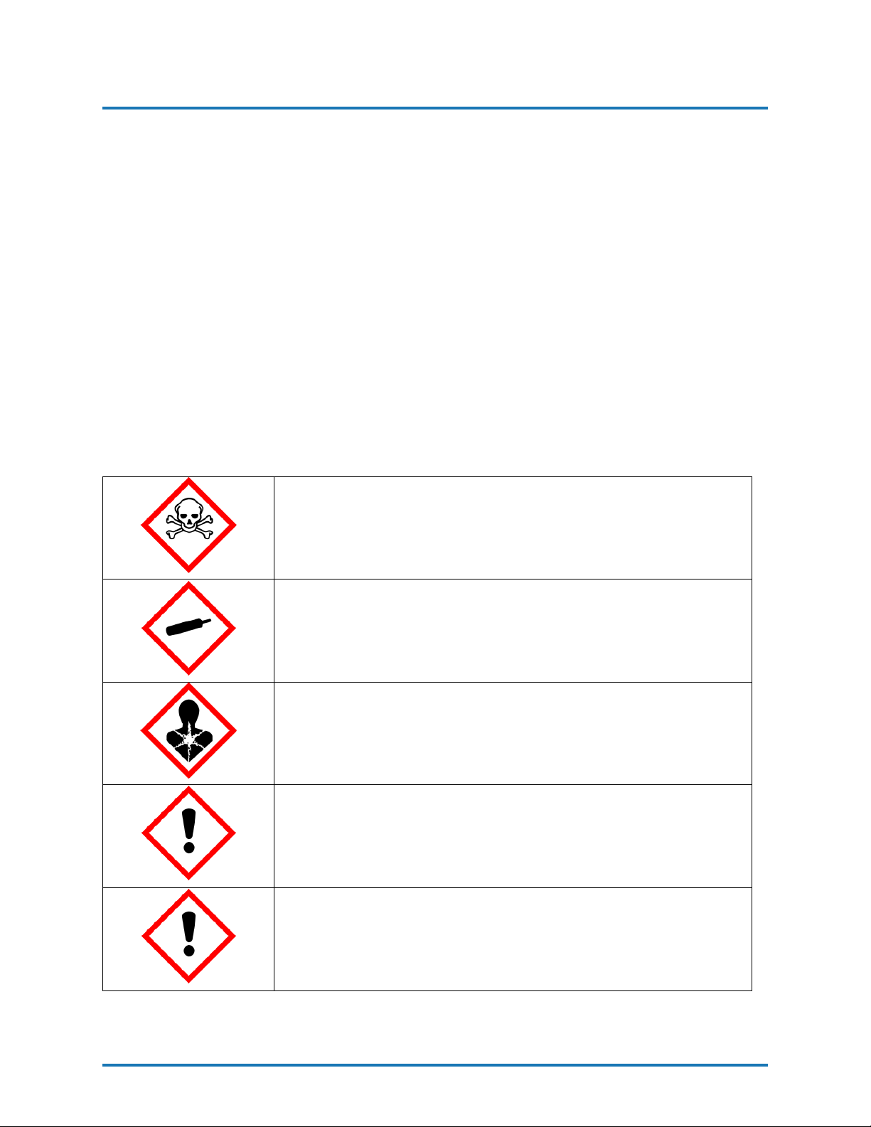
To prevent possible injury caused by incorrect handling of the
raw materials and solvents used in the process, carefully read
the Material Safety Data Sheet (SDS) provided by your supplier.
Deal with the waste caused according to current regulations.
To avoid damage caused by the impact of pressurized fluids, do
not open any connection or perform maintenance work on components subject to pressure until the pressure has been completely
eliminated.
Use suitable protection when operating, maintaining or being
present in the area where the equipment is functioning. This includes, but is not limited to, the use of protective goggles, gloves,
shoes and safety clothing and breathing equipment.
The equipment includes components that reach high temperatures
and can cause burns. Hot parts of the equipment must not be
handled or touched until they have cooled completely.
To prevent serious injury through crushing or amputation, do
not work with the equipment without the safety guards installed
on the moving parts. Make sure that all the safety guards are
correctly reinstalled at the end of the repair or maintenance work
of the equipment.
REVISION 1.1 8
Page 10

POLYURETHANE
MACHINERY
CORPORATION
PHDX-2 SERVICE MANUAL
3. CHARACTERISTICS
3 CHARACTERISTICS
The PHD Series Proportioner has been designed and built for the application of
polyurea chemical systems, polyurethane foam chemical systems, and some specific twocomponent epoxy systems.
3.1 PRINCIPAL HEATING SYSTEM
The Proportioner consists of one (1) Material Heater without internal seals. The
Low Pressure Heater has three (3) Heating Elements per fluid side rated at 1,250, 1,500,
or 1750 watts, each giving the Proportioner a total heat output of 7,500, 9,000, or 10,500
watts. The High Pressure Heater has four (4) Heating Elements per fluid side rated at 1750
watts, each giving the Proportioner a total heat output of 14,000 watts. Every heating
system provides the necessary control and safety components for their precise operation.
The Material Heater design allows for a controlled and precise temperature differential (∆T)
and material application temperatures of up to 190oF under ambient temperatures.
3.2 HOSE HEATING SYSTEM
The system is designed with a 3 kVA Isolation Transformer that enables effective
heating of up to a total hose length of 310 feet (also available with a 2kVA transformer
and a 5 kVA transformer for maximum hose lengths of 210 and 410, respectively). The
system includes an innovative hose heating concept in which the continuous braid tinnedcopper jacket is distributed evenly around the circumference of the hose providing a uniform
heating watt density and precise control of the material application temperature. This hose
heating element design is extremely resistant to fatigue failure.
REVISION 1.1 9
Page 11
POLYURETHANE
MACHINERY
CORPORATION
PHDX-2 SERVICE MANUAL
3. CHARACTERISTICS
3.3 DOUBLE ACTING OPPOSED PISTON METERING PUMPS
The opposed double acting Pump-Line is driven by a double ended Hydraulic Cylinder. The in-line pump system with opposed piston pumps provides a constant volume and
guarantees uniform pressures in both directions of pump movement.
3.4 PRESSURE BALANCE CONTROL SYSTEM
The Pressure Balance Control (PBC) system performs an automatic shutdown when
a chemical imbalance occurs. When the system is turned off, the Proportioner will perform
as if there is no PBC system and will continue pumping material. When the system is
turned on, it will continually monitor the pressure between the two chemicals (known as the
pressure differential). If the pressure differential becomes equal to or greater than the
maximum allowable pressure differential, the pumps will be shut off.
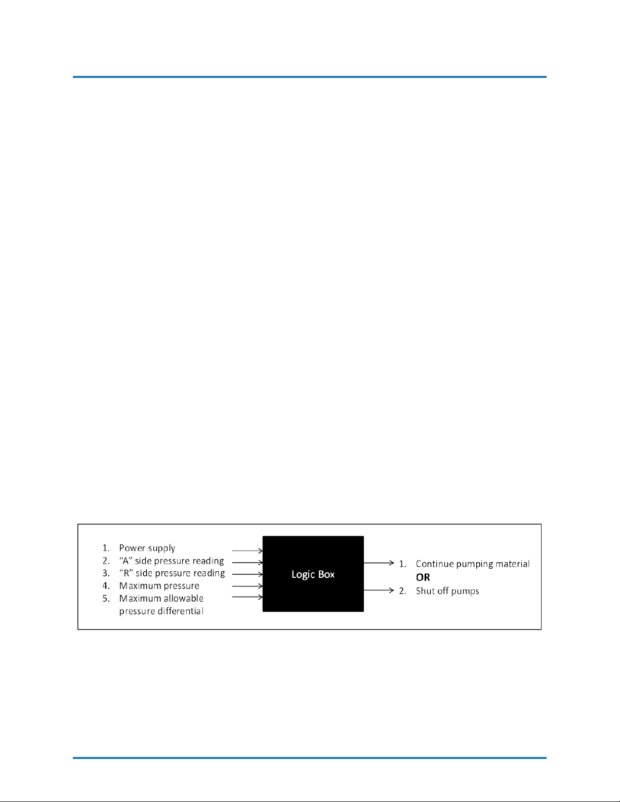
The Pressure Balance Control system can be simplified into a logic box diagram
with inputs and outputs. There are five inputs: the power supply from the main console, the
pressure readings from each chemical, the maximum pressure, and the maximum allowable
pressure differential. Inside the logic box, the actual pressure differential of the chemicals is
compared to the maximum allowable pressure differential. Depending on the circumstances
of all five inputs, there are only two possible outputs: either the pumps will continue to
pressurize and move material, or the pumps will shut off and flow will be lost.
Figure 1: Pressure Balance Control Logic Diagram
REVISION 1.1 10
Page 12

POLYURETHANE
MACHINERY
CORPORATION
4. TECHNICAL SPECIFICATIONS
PHDX-2 SERVICE MANUAL
4 TECHNICAL SPECIFICATIONS
4.1 ELECTRICAL
PHDX-2, Single Phase, 208-240V
Pressure Heater Size Electrical Consumption
9.0kW(4.5kW/side) 83A
3,000PSI
10.5kW(5.25kW/side) 90A
14.0kW(7.0kW/side) 105A
PHDX-2, Three Phase, 208-240V
Pressure Heater Size Electrical Consumption
9.0kW(4.5kW/side) 50A
3,000PSI
10.5kW(5.25kW/side) 53A
14.0kW(7.0kW/side) 62A
PHDX-2, Three Phase, 400V
Pressure Heater Size Electrical Consumption
9.0kW(4.5kW/side) 34A
3,000PSI
Material Heater Power Power Consumption
4.50kW/side(3x1500W/side) 9.0kW
5.25kW/side(3x1750W/side) 10.5kW
7.0kW/side(4x1750W/side) 14.0kW
Hose Transformer Power Consumption
Electrical Motor Power Consumption
CAUTION! Inside the console is a Terminal Strip for connecting the
main power (wire not supplied) to the PHD Series Proportioner. This
electrical connection must be made only by a qualified electrician.
10.5kW(5.25kW/side) 36A
14.0kW(7.0kW/side) 41A
70V 2kVA
90V 3kVA
120V 5kVA
PHDX-2 3hp
REVISION 1.1 11
Page 13
POLYURETHANE
MACHINERY
CORPORATION
4.2 MECHANICAL
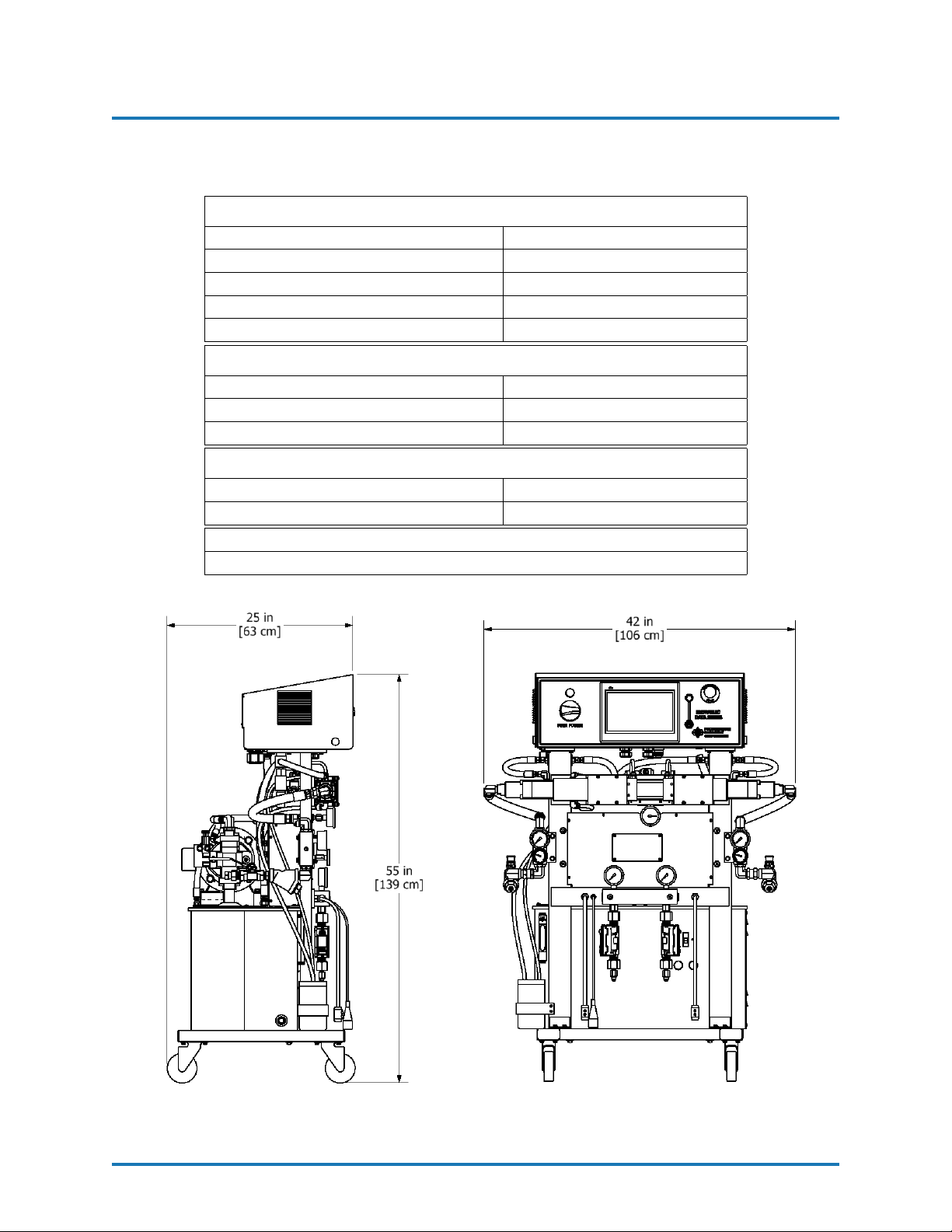
Maximum Working Pressure 2,000PSI(14MPa, 138bar)
Maximum Production 31lb/min(14kg/min)
Minimum Production 2lb/min(1kg/min)
Gallons per Stroke 0.01859gal/stroke(0.07037L)
Strokes per 55gal(200L) Drum 2,958strokes
2kVA Transformer 210ft(64m)
3kVA Transformer 310ft(95m)
5kVA Transformer 410ft(125m)
Hydraulic Tank Empty 415lbs(166kg)
Hydraulic Tank Full (12gal) 450lbs(197kg)
PHDX-2 SERVICE MANUAL
4. TECHNICAL SPECIFICATIONS
123 Pumps
Maximum Hose Length
Approximate Weight
Overall Dimensions(W x D x H)
42in x 25in x 55in (106cm x 63cm x 139cm)
Figure 2: Proportioner Dimensions
REVISION 1.1 12
Page 14
POLYURETHANE
MACHINERY
CORPORATION
5 DESCRIPTION
PHDX-2 SERVICE MANUAL
5. DESCRIPTION
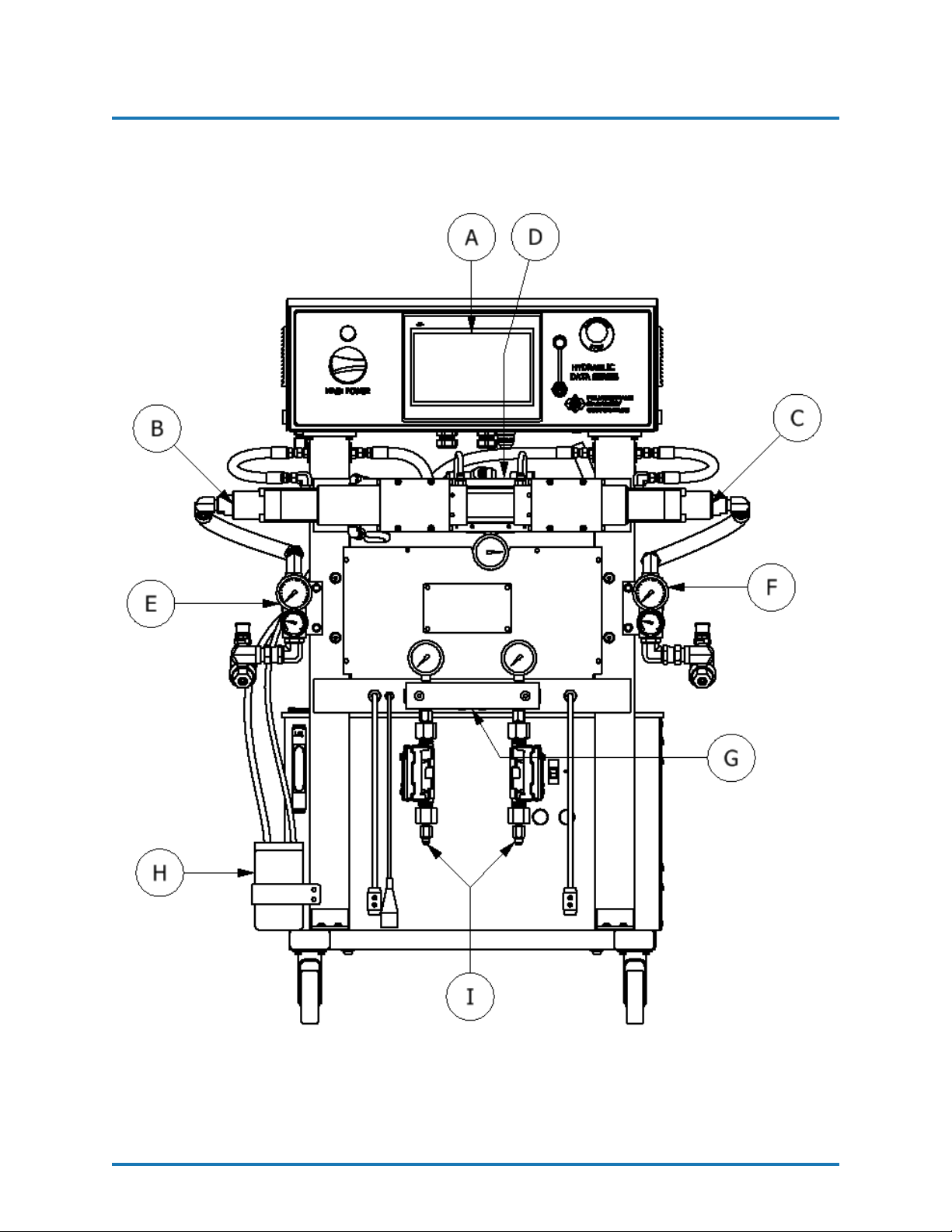
Figure 3: Component Identification - Front
REVISION 1.1 13
Page 15
POLYURETHANE
MACHINERY
CORPORATION
PHDX-2 SERVICE MANUAL
5. DESCRIPTION
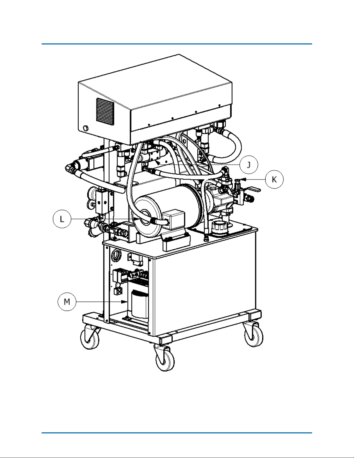
Figure 4: Component Identification - Back
REVISION 1.1 14
Page 16
POLYURETHANE
MACHINERY
CORPORATION
PHDX-2 SERVICE MANUAL
5. DESCRIPTION
A. Control Panel - Controls and regulates the operation of the PHD Series Proportioner.
B. Isocyanate (Iso, A) Metering Pump - Meters the Isocyanate material.
C. Polyol (Poly, R) Metering Pump - Meters the Polyol material.
D. Hydraulic Cylinder Assembly - Transfers power from hydraulic pump to material
pumps.
E. Isocyanate (Iso, A) Inlet Manifold Assembly - Provides Isocyanate temperature
and pressure readings prior to heating and pressurizing.
F. Polyol (Poly, R) Inlet Manifold Assembly - Provides Polyol temperature and pres-
sure readings prior to heating and pressurizing.
G. Exit Manifold Assembly - Provides pressure reading of material after heating and
pressurizing.
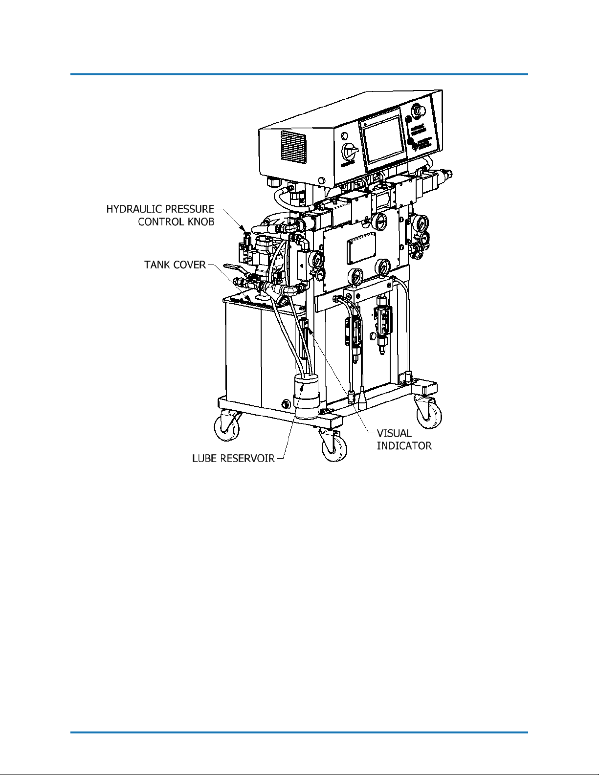
H. Isocyanate (Iso, A) Lube Reservoir - Provides lube to the Isocyanate pump shaft.
I. Flow Meters (Optional) - Monitor the flow rate of both materials exiting the Propor-
tioner.
J. Hydraulic Manifold Assembly - Provides pressure reading of hydraulic fluid and
controls direction of flow.
K. Hydraulic Pressure Control - Allows the pressure of the hydraulic system to be in-
creased or decreased. Turn clockwise to increase the pressure and counterclockwise
to decrease. To regulate the pressure of the hydraulic system, the NORMAL or RETRACT Pump Switch position must be selected.
L. Motor - Provides power for hydraulic pump.
M. Hose Heating Transformer - Right side (inside of hydraulic tank) - Supplies
the required voltage for material Heated Hoses.
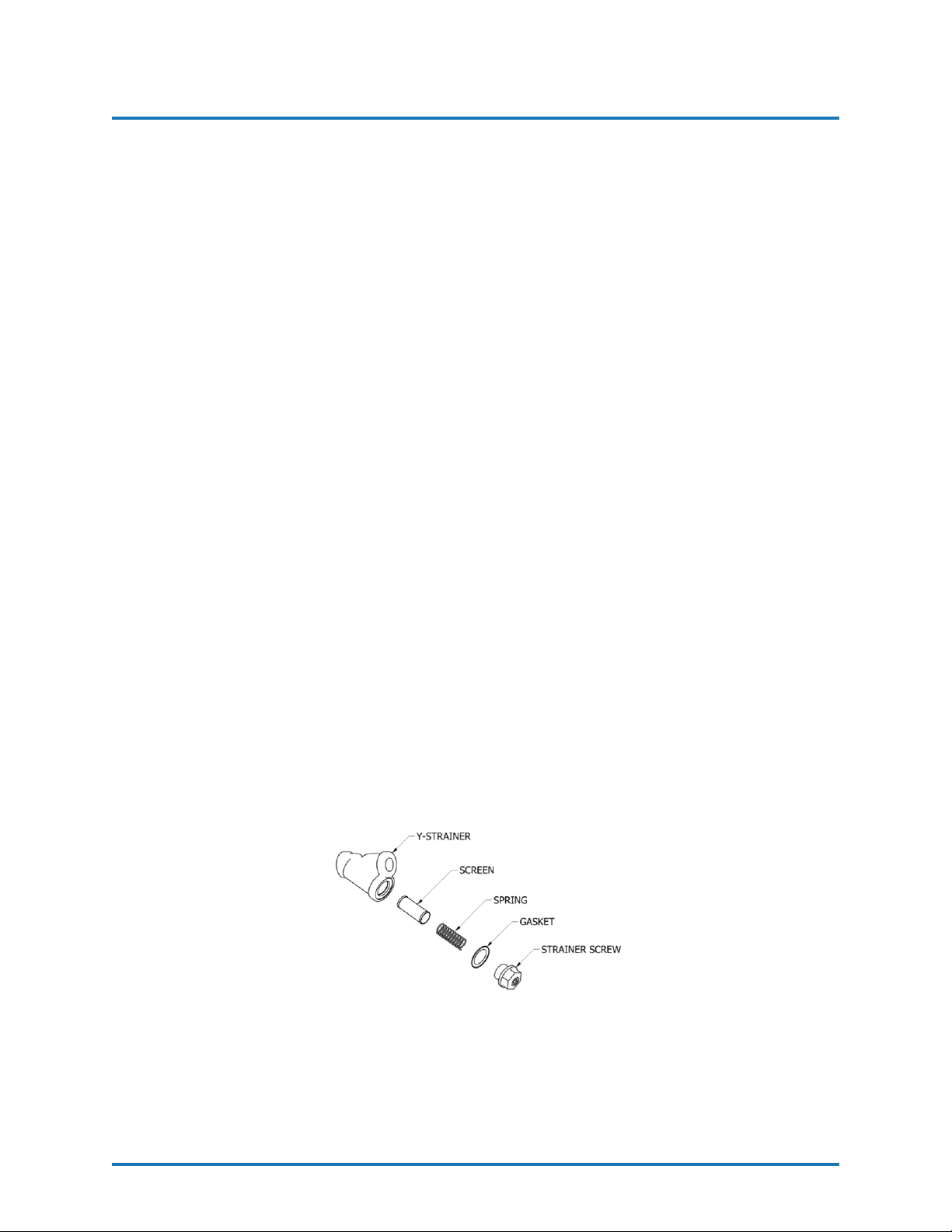
Figure 5: Y-Strainer Components
REVISION 1.1 15
Page 17
POLYURETHANE
MACHINERY
CORPORATION
PHDX-2 SERVICE MANUAL
5. DESCRIPTION
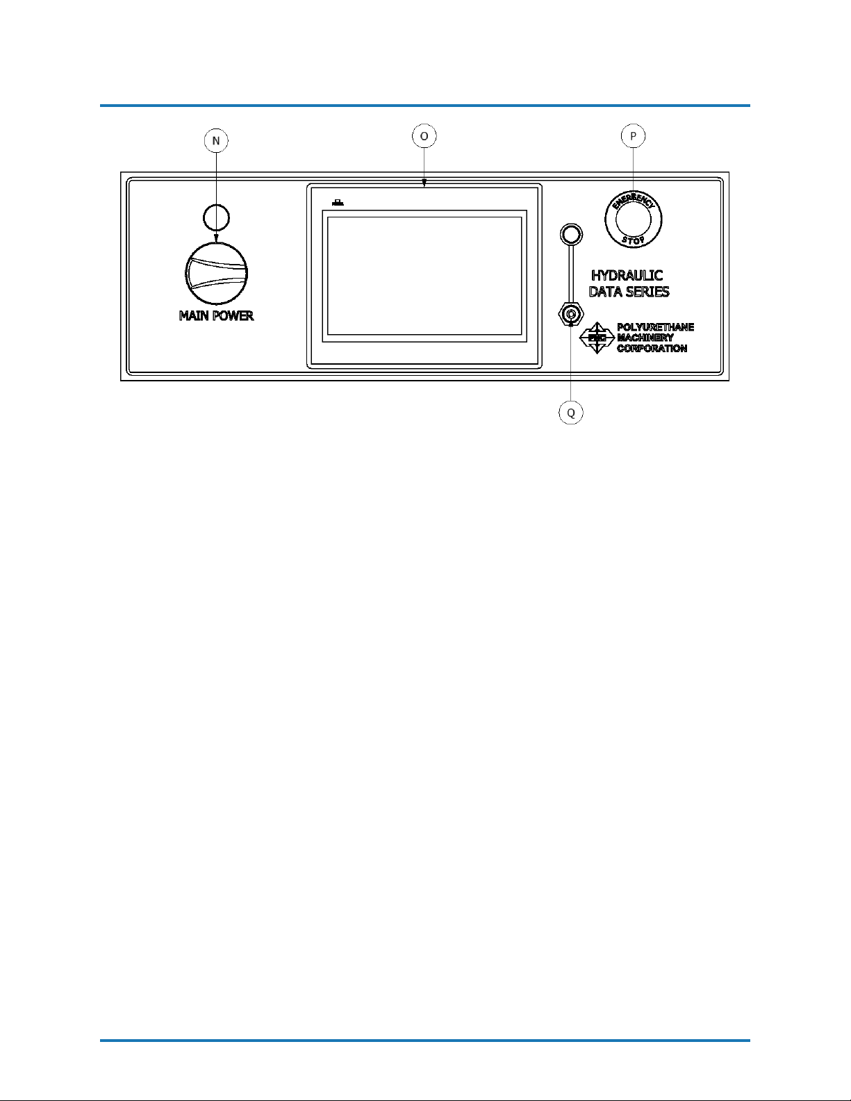
Figure 6: Front Panel Description
N. Main Power - Turns ON and OFF main power to the control panel. It must be turned
ON for any operation to be performed with the unit. When turned ON, the red pilot
will light.
O. Human-Machine Interface (HMI) - The HMI unit on this PHD Series Proportioner
is a 10.1” touch screen. This screen is used to operate the PHD Series Proportioner
and allows users to enable/disable optional functions of the Proportioner.
P. Emergency Stop - Interrupts the PHD Series control power circuit to stop all motion
and heating.
Q. USB Port - The USB Port is used to update the software of the PHD Series Proportioner
as well as to retrieve data collected during usage.
REVISION 1.1 16
Page 18
POLYURETHANE
MACHINERY
CORPORATION
5.1 OPERATION MENU
PHDX-2 SERVICE MANUAL
5. DESCRIPTION
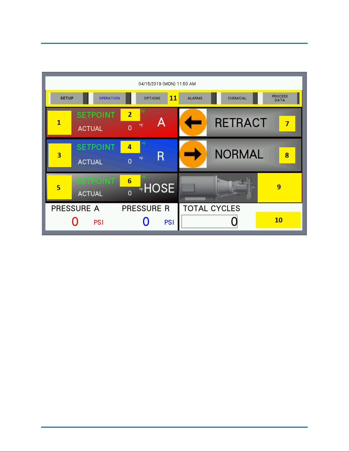
Figure 7: HMI Operation Menu
1 - A SIDE HEATER ON/OFF
2 - INPUT A SIDE HEATER TEMPERATURE
3 - R SIDE HEATER ON/OFF
4 - INPUT R SIDE HEATER TEMPERATURE
5 - HOSE HEAT ON/OFF
6 - INPUT HOSE HEAT TEMPERATURE
7 - PUMP TO RETRACT POSITION ON/OFF
8 - PUMP POWER ON/OFF
9 - MOTOR POWER ON/OFF
10 - CYCLE COUNTER RESET
11 - SCREEN NAVIGATION
REVISION 1.1 17
Page 19
POLYURETHANE
MACHINERY
CORPORATION
5.2 OPTIONS MENU
PHDX-2 SERVICE MANUAL
5. DESCRIPTION
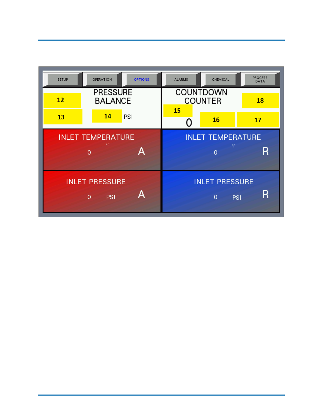
Figure 8: HMI Options Menu
12 - PRESSURE BALANCE CONTROL ON/OFF
13 - PRESSURE BALANCE ALARM RESET
14 - INPUT PRESSURE BALANCE CONTROL VALUE
15 - INPUT COUNTDOWN COUNTER
16 - SET COUNTDOWN COUNTER
17 - COUNTDOWN COUNTER RESET
18 - COUNTDOWN COUNTER ON/OFF
REVISION 1.1 18
Page 20
POLYURETHANE
MACHINERY
CORPORATION
5.3 ALARMS MENU
PHDX-2 SERVICE MANUAL
5. DESCRIPTION
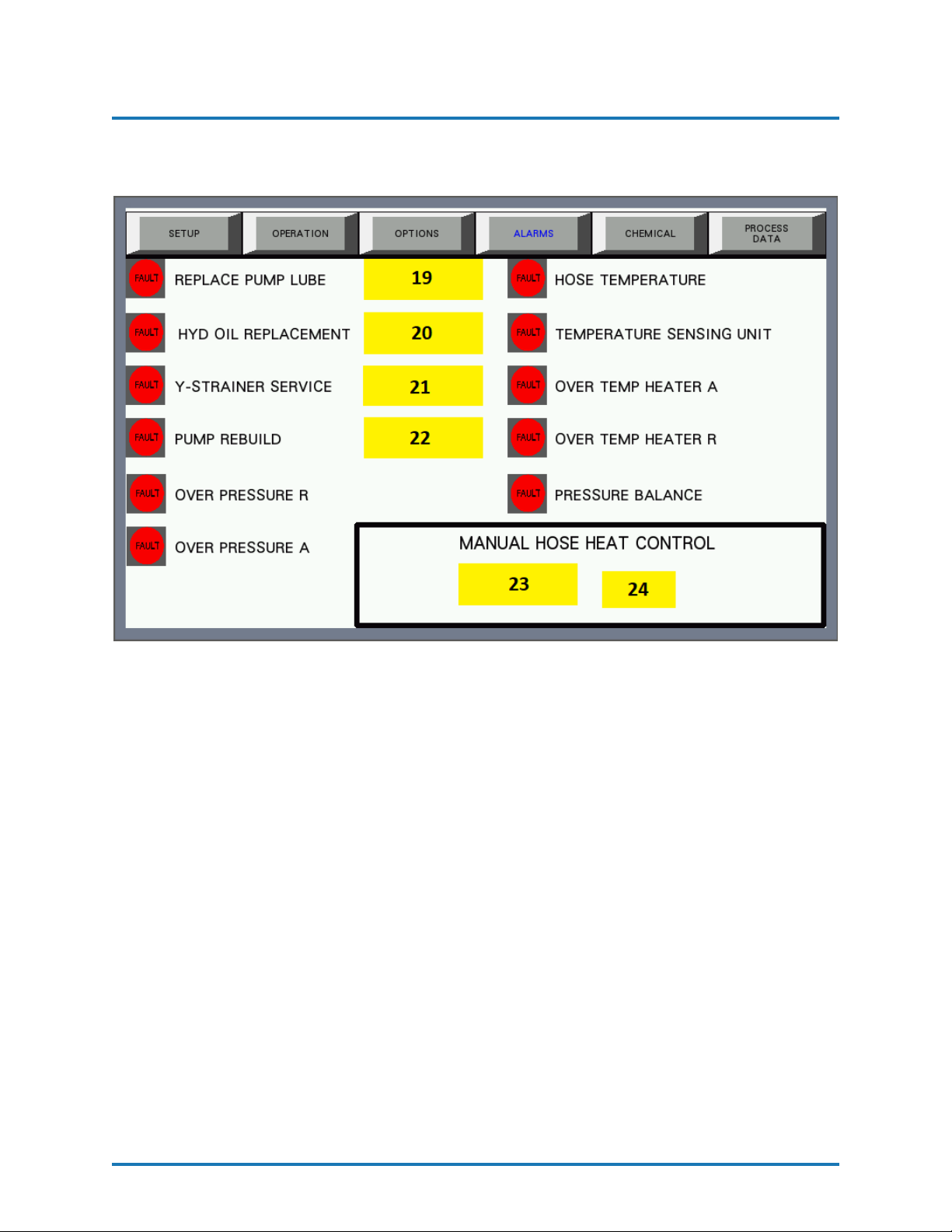
Figure 9: HMI Alarms Menu
19 - REPLACE PUMP LUBE ALARM RESET
20 - REPLACE HYDRAULIC OIL ALARM RESET
21 - SERVICE Y-STRAINER ALARM RESET
22 - PUMP REBUILD ALARM RESET
23 - MANUAL HOSE HEAT ON/OFF
24 - INPUT HOSE HEAT
REVISION 1.1 19
Page 21
POLYURETHANE
MACHINERY
CORPORATION
5.4 CHEMICAL MENU
PHDX-2 SERVICE MANUAL
5. DESCRIPTION
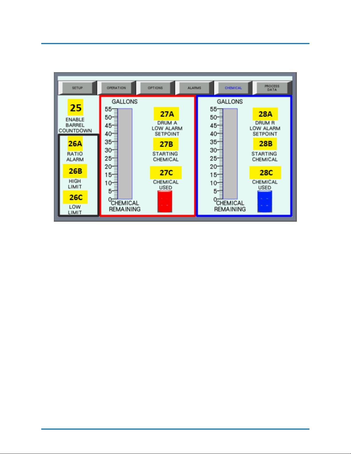
Figure 10: HMI Chemical Menu
25 - CHEMICAL COUNTDOWN COUNTER ON/OFF
26A - RATIO ALARM ON/OFF
26B - INPUT CHEMICAL RATIO HIGH LIMIT
26C - INPUT CHEMICAL RATIO LOW LIMIT
27A - INPUT LOW LIMIT FOR CHEMICAL A ALARM
27B - INPUT STARTING AMOUNT OF CHEMICAL A
27C - DISPLAYS AMOUNT OF CHEMICAL A USED
28A - INPUT LOW LIMIT FOR CHEMICAL R ALARM
28B - INPUT STARTING AMOUNT OF CHEMICAL R
28C - DISPLAYS AMOUNT OF CHEMICAL R USED
REVISION 1.1 20
Page 22
POLYURETHANE
MACHINERY
CORPORATION
5.5 PROCESS DATA MENU
PHDX-2 SERVICE MANUAL
5. DESCRIPTION
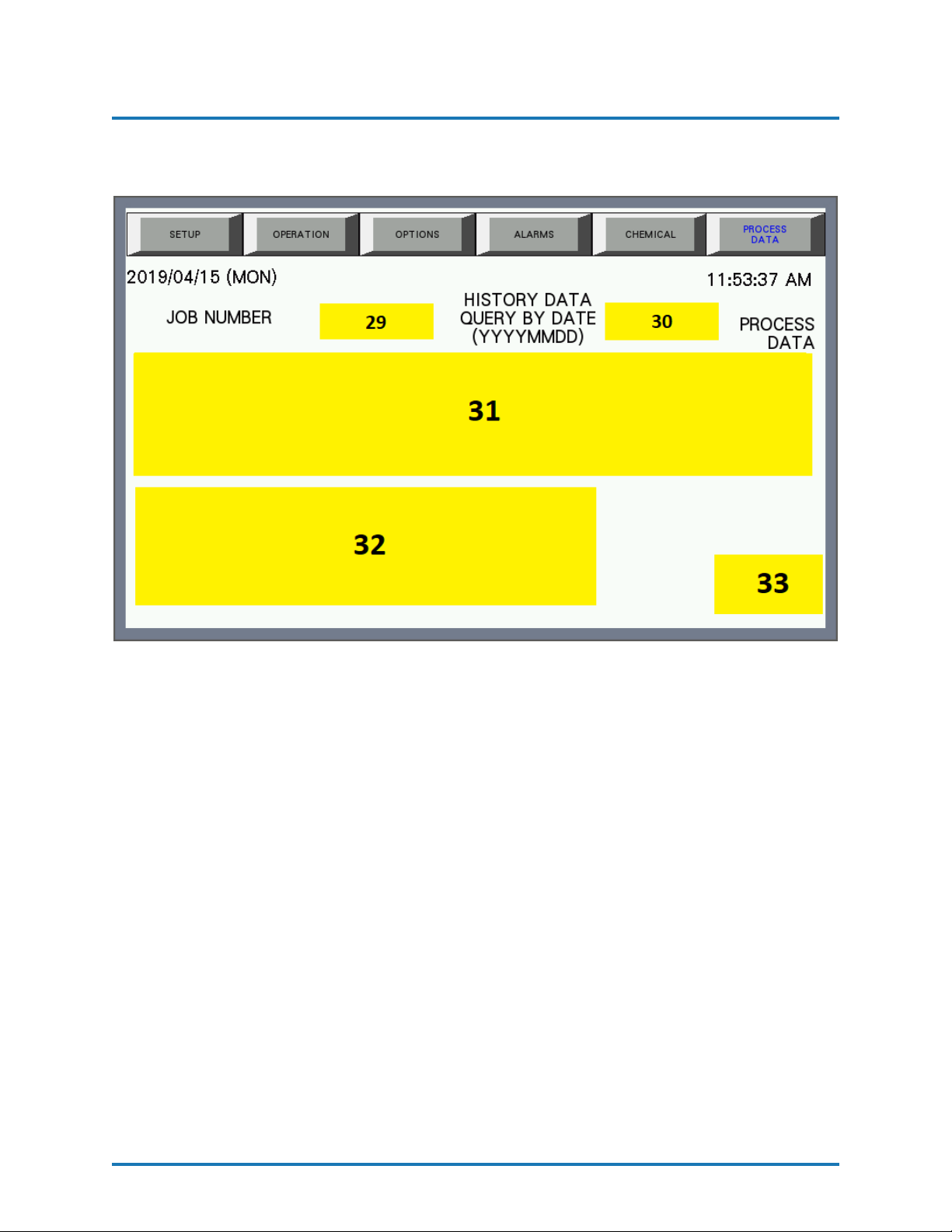
Figure 11: HMI Process Menu
29 - INPUT JOB NUMBER
30 - INPUT DATE OF JOB
31 - DATA DISPLAY
32 - ALARM DISPLAY
33 - USB EJECT
REVISION 1.1 21
Page 23
POLYURETHANE
MACHINERY
CORPORATION
5.6 SETUP MENU
PHDX-2 SERVICE MANUAL
5. DESCRIPTION
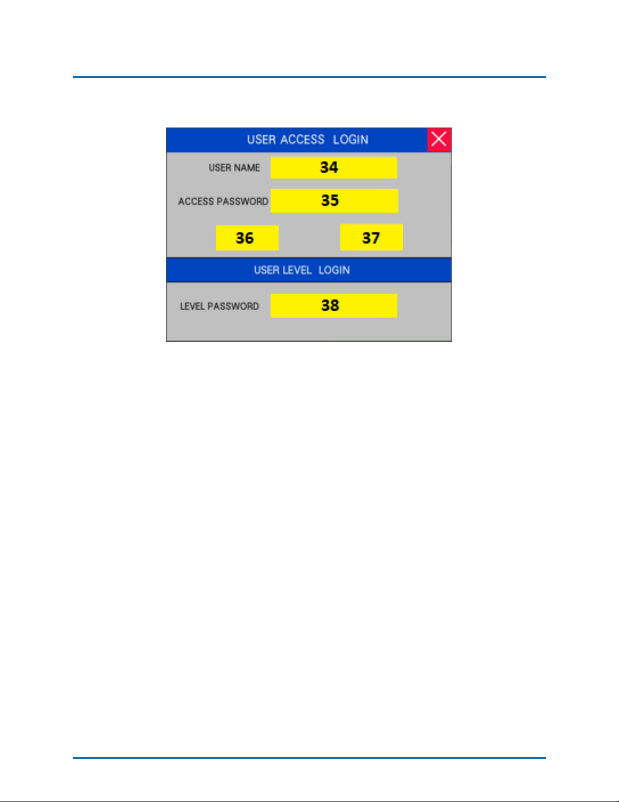
Figure 12: HMI Setup Menu
34 - INPUT USER NAME
35 - INPUT PASSWORD
36 - LOGIN
37 - LOGOUT
38 - INPUT LEVEL PASSWORD
REVISION 1.1 22
Page 24
POLYURETHANE
MACHINERY
CORPORATION
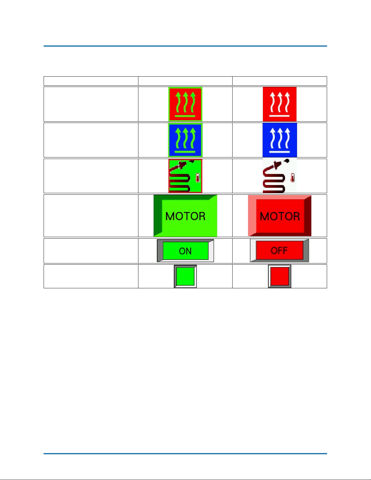
5.7 BUTTON APPEARANCE
CONTROL ON OFF
Heater A (Figure 7,
Item 1)
Heater R (Figure 7,
Item 3)
Hose Heat (Figure 7,
Item 5)
PHDX-2 SERVICE MANUAL
5. DESCRIPTION
Motor (Figure 7, Item
9)
Standard Button #1
Standard Button #2
REVISION 1.1 23
Page 25
POLYURETHANE
MACHINERY
CORPORATION
PHDX-2 SERVICE MANUAL
6. INSTALLATION
6 INSTALLATION
WARNING! Use suitable protection and follow the recommenda-
tions in the Safety Information enclosed and provided by material
suppliers when installing or working with the Proportioner.
CAUTION! Make sure the power cable is disconnected from the
main power source before connecting to the Terminal Strip in the
Console.
NOTE! To ensure the PHD Series Proportioner works correctly,
the electrical supply must meet the specifications indicated on the
Serial Number Placard affixed to the Electrical Console.
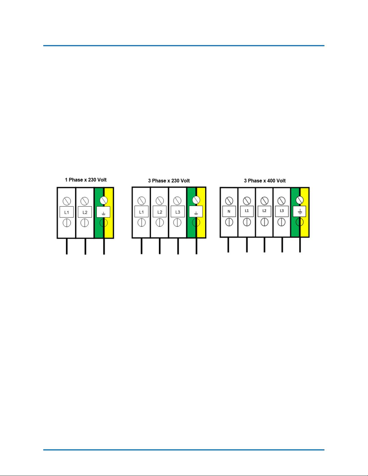
Figure 13: Electrical Installation
1. Insert the main power cable by passing it through the wire stop at the bottom of the
electrical console and connect as shown in the diagram above.
2. Fill the Hydraulic Reservoir with 10 gallons (37 Liters) of approved hydraulic fluid.
See page 59 for hydraulic oil specifications.
NOTE! Do not fill the tank to maximum capacity;
use the Visual Level Indicator on the tank to make
sure the amount of hydraulic fluid is not more than
10 gal (37 L) or 80% of the tanks maximum capacity.
3. To check the level of the hydraulic fluid in the Hydraulic Pump Case, disconnect the
Hydraulic Hose from the 90 degree fitting and remove Fitting from Hydraulic Case.
Add fluid as required. Reattach Fitting and Hydraulic Hose. Turn the hydraulic
pressure control knob counter clockwise until it stops, that is the lowest hydraulic
pressure setting.
REVISION 1.1 24
Page 26
POLYURETHANE
MACHINERY
CORPORATION
PHDX-2 SERVICE MANUAL
6. INSTALLATION
Figure 14: Component Identification - Misc
CAUTION! Ensure that the emergency stop is not engaged.
4. Three Phase Proportioner Only: Check the Electric Motor to ensure rotation is
clockwise when viewing the end of the Electric Motor. A counter clockwise rotation
indicates two of the incoming power leads need to be reversed.
CAUTION! Ensure Main Power Switch is OFF and in-
coming power is locked OFF before reversing power
leads.
Recheck rotation before proceeding with Installation.
5. Fill the Lube Reservoir with PMC Pump Lube or suitable diluents. It is not necessary
to prime the system.
REVISION 1.1 25
Page 27

POLYURETHANE
MACHINERY
CORPORATION
PHDX-2 SERVICE MANUAL
6. INSTALLATION
6.1 HEATED HOSE INSTALLATION
CAUTION! The material delivery Heated Hoses are color coded
Red and Blue, allowing the user to recognize them. The Red corresponds to the Isocyanate (Iso, A) and the Blue to the Polyol
(Poly, R). To avoid connection errors, the Coupling Connections of
the Iso (A) and Poly (R) Heated Hoses are different sizes to ensure
correct orientation.
NOTE! The material delivery Heated Hoses are capped at the
ends to prevent absorbing moisture. Do not remove caps until
the Heated Hoses are going to be installed on the Proportioner.
1. Lay out all the Heated Hose assemblies end to end aligning the Iso “A” (red) and Poly
“R” (blue) and connect the respective Coupling Connections using the appropriate
sized open-end wrench after ensuring Heated Hose assemblies lay flat.
CAUTION! Take care to not cross-thread or over-tighten
the Coupling Connections. Thread seal tape or compound is not recommended for these tapered seat Coupling Connections.
2. Connect the material Heated Hoses to the outlets of the respective Exit Manifold
Assembly. Iso (A) Heated Hose to the JIC fitting on the left side of the Exit Manifold
Assembly and the Poly (R) Heated Hose to the JIC fitting on the left side of the Exit
Manifold Assembly. Ensure the Heated Hose assemblies lay flat.
3. Connect Air Hose Coupling Connections.
4. Connect the Heated Hose power wires to the “Fast-Lock” Connector (Part# KT00029A) coming from the Hose Heat Transformer as follows:
(a) Loosen the Socket Head Set Screw to allow insertion of the Heated Hose electrical
wire Terminal.
(b) Insert the Terminal into the “Fast-Lock” Connector Body.
(c) Securely tighten the Socket Head Set Screw.
(d) Install electrical tape around Connector Body.
NOTE! A good practice is to add some dielectric grease
(Permatex 67VR or equivalent) to the outside of the
Terminal, where the electrical connection is made, prior
to insertion.
5. Repeat the above steps to connect the “Fast-Lock” Connectors that you will find on
all Heated Hose power wire.
REVISION 1.1 26
Page 28
POLYURETHANE
MACHINERY
CORPORATION
PHDX-2 SERVICE MANUAL
6. INSTALLATION
CAUTION! Ensure the proper mechanical and electri-
cal connections of the Heated Hoses are made to avoid
possible material leakage and Hose heat problems.
6. It is recommended the TSU be installed between the last section of Heated Hose and
the Gun Whip. Carefully straighten the sensing wire, inserting it in the Iso (A) Heated
Hose and tighten fluid fittings with appropriate sized open-end wrenches.
CAUTION! To protect the TSU sensor, you must pay
special attention not to kink or excessively bend the
Heated Hoses. Do not coil the Heated Hoses with a
diameter of less than 4 feet (1.22 Meters).
Figure 15: Temperature Sensing Unit
(TSU) Part# EL-51A-4
Replacement Sensor Part# EL-51A-2
CAUTION! Connecting the TSU between the first and
second section of Heated Hose results in the TSU sensing
the material temperature exiting the Heater and not the
inside of the Heated Hose near the Spray Gun.
REVISION 1.1 27
Page 29

POLYURETHANE
MACHINERY
CORPORATION
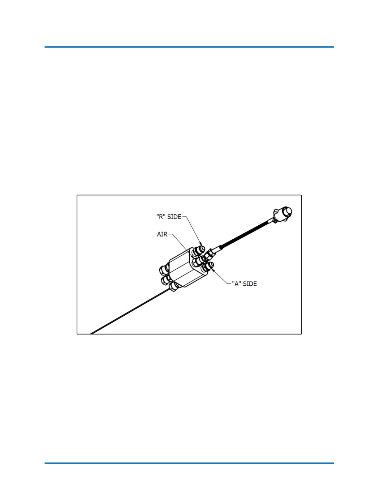
7. Ensure the Manual Valves are CLOSED and connect the Coupling Block to the Heated
Gun Whip.
PHDX-2 SERVICE MANUAL
6. INSTALLATION
CAUTION! Excessive force closing or opening the Man-
ual Valves may result in damage to the Manual Valves
and/or Coupling Block.
8. Connect the Transfer Pump/ Heated Hose Assemblies/Air Supply and Air Dryer systems as required. Review the Installation Instructions for each to ensure proper set-up
and operation.
9. Install the Material Transfer Pumps as follows:
WARNING! If Transfer Pumps have been previously used, pay
special attention to connect each Pump to its specific material.
Inadvertently changing the Transfer Pumps will cause a chemical
reaction rendering them useless.
NOTE! Placing a tape of the same color as of the Mate-
rial Delivery Hoses (red for the Iso (A), blue for the Poly
(R)) on each Transfer Pump would be a good method for
minimizing errors in connection.
a. Make sure that the Inlet Valves on the Proportioner are closed.
b. Connect one end of the Polyol (R) Material Delivery Hose (3/4” thread) to the
Proportioner Polyol (R) Inlet Valve and the other end to the Polyol (R) Transfer
Pump.
c. Connect one end of the Iso (A) Material Delivery Hose (1/2” thread) to the
Proportioner Iso (A) Inlet Valve and the other end to the Iso Transfer Pump.
d. Connect the air hose to the Transfer Pumps after ensuring each Transfer Pump
Shut-Off Valve is CLOSED.
NOTE! To avoid errors in connection, the Coupling con-
nections of the Iso (A) and Poly (R) Material Delivery
Hoses are different sizes, making it difficult to swap connections.
10. Ground the Transfer Pump as recommend by the material supplier. The movement of
product inside the Hoses can cause static electricity and produce electrical discharges.
11. Connect air to the air line coming off the first section of hose (90-110 psi, 6-8 bar)
REVISION 1.1 28
Page 30

POLYURETHANE
MACHINERY
CORPORATION
PHDX-2 SERVICE MANUAL
6. INSTALLATION
6.2 HOSE HEAT TRANSFORMER
The Hose Heat Transformer offers the ability of connecting to different output voltages
depending on the total length of the Heated Hose in use, maximizing the heating
ability of the Heated Hose. The factory setting is 18 volts for use with 60 feet
of Heated Hose. Before starting the Proportioner, ensure the setting matches the
Heated Hose length installed. If Heated Hose sections are added or removed, the Tap
setting should be changed to a setting which will limit the maximum amperage in the
Heated Hose to 52 amps. The suggested settings are listed in the table below.
RECOMMENDED TAP SETTINGS
Tap Hose Length (Feet) Hose Length (Meters)
120V 410 125.0
105V 360 109.7
90V 310 94.5
75V 260 79.5
60V 210 64.0
45V 160 48.8
30V 110 33.5
18V 60 18.3
Figure 16: Transformers
*90V transformers (shown above) allow for a maximum hose length of 310 ft (94.5 m). 120V
transformers allow for a maximum hose length of 410 ft (125 m).
REVISION 1.1 29
Page 31

POLYURETHANE
MACHINERY
CORPORATION
PHDX-2 SERVICE MANUAL
7. PROPORTIONER PURGING
7 PROPORTIONER PURGING
WARNING! Use suitable Personal Protection Equipment
(PPE) and follow the recommendations in the Safety Information provided by product suppliers when installing or working
with the unit.
WARNING! Do not turn the Temperature Controllers ON
until the Proportioner purging procedure is complete and the
Primary Heaters and Heated Hoses are filled with material.
NOTE! Before using the Proportioner it is necessary to purge
the entire system, including Heated Hoses of mineral oil left
over from Quality Control testing and air. The following procedure is also followed to purge air entrapped by running out
of material in the supply Drum/Reservoirs resulting in a significant indicated material pressure imbalance as indicated by
the Pressure Gauges and sprayed material.
1. Ensure the following before proceeding:
a. Air supply to Transfer Pumps is 90 - 110 psi (6 - 8 bar).
b. Proportioner inlet ball valves are CLOSED.
c. All connections are tight.
d. Material should be stored to the material suppliers recommended temperatures.
e. Spray gun coupling block is installed and manual valves are closed.
2. Slowly OPEN the Poly (R) Transfer Pump Air Shut-Off Valve allowing Pump to cycle
slowly as it fills the Material Delivery Hose to the Proportioner. Check for leaks.
3. OPEN Poly (R) Coupling Block Manual Valve over a waste container.
4. Slowly OPEN Proportioner Poly (R) Inlet Valve allowing Transfer Pump to move
material through the system. When all spitting of air stops and all traces of mineral
oil have disappeared, CLOSE Poly (R) Coupling Block Manual Valve. Clean Coupling
Block.
5. Repeat steps 2 to 4 for Iso (A) side.
CAUTION! Properly dispose of all waste chemicals in accor-
dance with all applicable local, state and federal codes. DO
NOT turn on the Auto Countdown Switch or the Pressure
Balance Control Switch.
REVISION 1.1 30
Page 32

POLYURETHANE
MACHINERY
CORPORATION
PHDX-2 SERVICE MANUAL
7. PROPORTIONER PURGING
6. Turn Hydrualic Pressure Control (Item K, Figure 4) fully COUNTERCLOCKWISE.
7. Turn ON Main Power (Item N, Figure 6).
8. Turn ON Motor Power (Item 9, Figure 7). Button will turn green when activated.
9. Activate Pump Power (Item 8, Figure 7). The button will turn green and the pump will
activate. Turn Hydraulic Pressure Control CLOCKWISE increasing material pressure
to 400 psi (28 bar). Both Material Pressure Gauges on the Exit Manifold Assembly (Item G, Figure 3) should approximately read the same. Check all Heated Hose
Coupling connections for leakage.
10. Check all TSU and ”Fast-Lock” connections for leaks.
11. Bundle all Heated Hose Connections ensuring that there are NO kinks in the TSU
Cable or Air Hose. Wrap with Electrical Tape to securely hold all components in place
and minimize places for bundle to snag onto job site protrusions.
REVISION 1.1 31
Page 33

POLYURETHANE
MACHINERY
CORPORATION
8. PRESSURE BALANCE CONTROL
PHDX-2 SERVICE MANUAL
8 PRESSURE BALANCE CONTROL
The PHD Series Proportioner has been designed with a pressure balance control system.
This system will give the operator of this machine the ability to control a pressure imbalance
within certain predetermined parameters.
8.1 OPERATION
The Pressure Balance Control menu is located in the Options tab. This screen is detailed in
Section 5.2 on page 18.
• Input Pressure (Item 14, Figure 8) - Press and a pop up will appear contain-
ing a standard number pad. This is where the desired value for the Pressure Balance
Control is input.
• Pressure Balance Control ON/OFF (Item 12, Figure 8) - Press to acti-
vate the Pressure Balance Control option. Once activated the button will turn GREEN
and read ON. Press to deactivate the Pressure Balance Control option.
• Pressure Balance Control Alarm Reset (Item 13, Figure 8) - Once a value is
input and the option is activated, the PLC will continually monitor pressure on both
sides of the Proportioner. In the event that the pressure differential between both
sides of the Proportioner is equal to or larger than the selected number, an alarm will
trigger and the Proportioner will stop pumping. Once the issue is resolved and
is pushed, the alarm will reset and allow the Proportioner to pump again.
REVISION 1.1 32
Page 34

POLYURETHANE
MACHINERY
CORPORATION
PHDX-2 SERVICE MANUAL
9. TEMPERATURE CONTROLS
9 TEMPERATURE CONTROLS
WARNING! Do not turn the Temperature Controllers ON
until the Proportioner Purging procedure is complete and the
Primary Heaters and Heated Hoses are filled with material.
9.1 OPERATION
The Temperature Controller menu is located in the ”Operation” tab. This screen is detailed
in Section 5.1 on page 17.
• Input Heater A Temperature (Item 2, Figure 7) - Press and a pop up will
appear containing a standard number pad. This is where the desired value for the A
side Heater is input.
• A side Heater ON/OFF (Item 1, Figure 7) - Press to activate the A side
Heater. While the A side Heater is active the button will appear as .
• Input Heater R Temperature (Item 4, Figure 7) - Press and a pop up will
appear containing a standard number pad. This is where the desired value for the R
side Heater is input.
• R side Heater ON/OFF (Item 3, Figure 7) - Press to activate the R side
Heater. While the R side Heater is active the button will appear as .
• Input Hose Heat Temperature (Item 6, Figure 7) - Press and a pop up
will appear containing a standard number pad. This is where the desired value for the
Hose Heater is input.
• Hose Heat ON/OFF (Item 5, Figure 7) - Press to activate the Hose Heater.
While the Hose Heater is active the button will appear as .
REVISION 1.1 33
Page 35

POLYURETHANE
MACHINERY
CORPORATION
PHDX-2 SERVICE MANUAL
10. START-UP
10 START-UP
NOTE! Follow the recommended procedure in the order shown.
CAUTION! The Start-up procedures assume that all steps in Pro-
portioner purging (Section 7) have been performed and no problems were found.
1. Check the hydraulic fluid level and service as required.
2. Make sure the materials have been stored at the manufacturer’s recommended temperature. Ask your material supplier for information (Safety Data Sheet) on the minimum
storage temperature.
3. Y-Strainer screens should be checked routinely.
4. Connect air supply to the two Transfer Pumps and ensure Air Valves are in the full
OPEN position. OPEN both Proportioner Material Inlet Ball Valves.
CAUTION! Remove all Heated Hose sections from coiled storage
and lay flat to eliminate heat build-up and possible Heated Hose
failure.
5. Turn ON Main Power (Item N, Figure 6).
6. Turn ON Hose Heater (Item 5, Figure 7) and confirm material set-point temperature
as recommended by the material supplier or application conditions.
CAUTION! To avoid excessive pressure in the Proportioner, wait
for the Hose Heater to reach its set-point temperature before continuing.
7. Turn ON each Primary Heater and confirm material set-point temperature as required
by the material supplier or application conditions has been reached.
8. Turn ON Motor Power (Item 9, Figure 7).
9. Turn ON Pump to NORMAL (Item 8, Figure 7).
NOTE! The Material Pressure Gauges should be approximately
equal and remain constant throughout the Metering Pump cycle.
If not, refer to the Troubleshooting section (Section 12).
REVISION 1.1 34
Page 36

POLYURETHANE
MACHINERY
CORPORATION
PHDX-2 SERVICE MANUAL
10. START-UP
10. Using the Hydraulic Pressure Control (Item K, Figure 4), adjust to the required stall
pressure and check each Material Pressure Gauge.
11. Countdown Counter - Follow the steps below to set the Auto Shut Down Counter:
a. Press and input desired number of cycles.
b. Press to submit the value to the counter.
c. When the counter counts down to zero the machine will stop and the pump direc-
tional light will be off.
d. To reset the counter press and the Proportioner will continue to pump.
12. Proceed with Installation and Start-up of the Spray Gun as per the Gun manual.
Model Pump Size Cycles per Gallon Cycles per Liter
PHDX-2 (2,000PSI) 123 27 Cycles 7.1 Cycles
Stall pressure: When materials are at recommended application temperature and
Metering Pumps are pressurized but not moving. This pressure is normally 100–200
psi (7-14 Bar) greater than the developed spray pressure as recommended by the
material supplier.
REVISION 1.1 35
Page 37

POLYURETHANE
MACHINERY
CORPORATION
PHDX-2 SERVICE MANUAL
11. SHUT-DOWN
11 SHUT-DOWN
11.1 SHORT-TERM
Follow the procedure below for temporary shut-downs, such as lunch breaks:
1. Turn OFF pump RETRACT. The button should appear as when inactive.
2. Turn OFF pump NORMAL. The button should appear as when inactive.
3. Turn OFF MOTOR POWER. The button should appear as when inactive.
4. Turn OFF both “A” and “R” Heaters. The buttons should appear as and when
inactive.
Hose Heater should remain ON. Never leave Proportioner ON if unattended.
5. CLOSE Spray Gun Manual Valves.
11.2 LONG-TERM
Follow the procedure below for shut-downs when work is stopped for the day:
1. Turn ON the pump NORMAL and RETRACT. The buttons should appear as
when active.
2. Spray off the application surface until Material Pressure Gauge (Item G, Figure 3)
readings begin to fall.
CAUTION! To avoid possible Proportioning Pump Seal weepage,
and moisture vapor drive into the Heated Hoses, the system pressure should not be reduced to zero. It is recommended to lower
the system pressure to a minimum of 400 psi (28 bar).
3. CLOSE the Spray Gun Coupling Block Manual Valves.
4. Turn OFF MOTOR POWER. The button should appear as when inactive.
5. Turn OFF both “A” and “R” Heaters. The buttons should appear as and when
inactive.
6. Turn OFF the Main Power (Item N, Figure 6).
7. Disconnect the air supply to the two Transfer Pumps and CLOSE the Proportioner
Material Inlet Valves.
CAUTION! Excessive force opening or closing the Manual Valves
may result in damage to the Manual Valves and/or Coupling Block.
REVISION 1.1 36
Page 38

POLYURETHANE
MACHINERY
CORPORATION
PHDX-2 SERVICE MANUAL
12. TROUBLESHOOTING
12 TROUBLESHOOTING
This PHD Series Proportioner has been designed and built to withstand severe working conditions with a high degree of reliability, provided that it is used in a suitable application
by a properly trained operator. This chapter contains information on possible faults that
may interrupt the operation of the PHD Series Proportioner. The information provided will
serve as a guideline to detect and resolve problems. In any case, feel free to contact your
authorized PMC distributor, where a qualified technician will advise you.
WARNING! Only qualified personnel should perform troubleshoot-
ing; unqualified personnel may cause damage to the unit and put
the operator at risk.
To prevent possible injury caused by incorrect handling of the
raw materials and solvents used in the process, carefully read
the Safety Data Sheet (SDS) provided by your supplier. Deal
with the waste caused according to current regulations.
To avoid damage caused by the impact of pressurized fluids, do
not open any connection or perform maintenance work on components subject to pressure until the pressure has been completely
eliminated.
Use suitable protection when operating, maintaining or being
present in the area where the equipment is functioning. This includes, but is not limited to, the use of protective goggles, gloves,
shoes and safety clothing and breathing equipment.
The equipment includes components that reach high temperatures
and can cause burns. Hot parts of the equipment must not be
handled or touched until they have cooled completely.
To prevent serious injury through crushing or amputation, do
not work with the equipment without the safety guards installed
on the moving parts. Make sure that all the safety guards are
correctly reinstalled at the end of the repair or maintenance work
of the equipment.
REVISION 1.1 37
Page 39

POLYURETHANE
MACHINERY
CORPORATION
PHDX-2 SERVICE MANUAL
12. TROUBLESHOOTING
When the proportioner experiences an error an alarm will flash on the current
menu in use. This alarm is shown below. Upon activation of this alarm the
machine will cease to function. The proportioner will only allow further usage
once the parameter that is causing the fault has been fixed. To troubleshoot the
fault go into the alarms menu.
The alarms menu below shows the current alarms triggered with a description
of the components affected. When an alarm is triggered the red circle that says
FAULT will be flashing.
REVISION 1.1 38
Page 40

POLYURETHANE
MACHINERY
CORPORATION
PHDX-2 SERVICE MANUAL
12. TROUBLESHOOTING
12.1 HEATERS
WARNING! Only qualified personnel should perform troubleshoot-
ing; unqualified personnel may cause damage to the unit, personnel,
or property and put the operator at risk. The Heaters are components that reach high temperatures; you must wait until they cool
before handling.
NOTE! The Thermal Limit Switch is a safety switch in contact with
the Heater Body. If the surface temperature exceeds 220◦F (109◦C)
the Limit Switch will shut off the Heater power. The Limit Switch
will not reset until the temperature in the Heater is below 190◦F
(88◦C). The system is designed that in case of an over temperature,
a contactor located in the console will open and disable power to
both Heaters and the Hose.
Frequent Heater Problems
Primary heater does not heat and the display on the HMI shows ambient
temperature.
Primary heater does not heat and the display on the HMI shows an error. Page 41
Primary heater shows excessive temperature and the circuit has turned off. Page 41
Primary heater temperature drops excessively while spraying. Page 41
Follow the recommended procedure in the indicated order to solve the problem and avoid
unnecessary repairs. Make sure all features are in the correct setting before determining the
existence of a fault.
Page 40
REVISION 1.1 39
Page 41

POLYURETHANE
MACHINERY
CORPORATION
PHDX-2 SERVICE MANUAL
12. TROUBLESHOOTING
• Problem: Primary heater does not heat and the display on the HMI shows ambient
temperature.
Solutions:
1. Check the heater breaker in the main console and reset the breaker. If it continues
to trip, wrap an Amp Clamp around one of the wires coming off the breaker. If
the Amperage reading does not exceed the rating of the breaker, the breaker needs
to be replaced. If the breaker draws more than its rating the most likely cause is
that one or more of the fire rods located in the heater are shorted.
If the breaker is not tripped, move on to the next step.
2. Open the console top and locate the solid state relays for the heaters, looking over
the console top from the front of the machine. There are two relays to the left
bottom of the console, the one to the far left is for the “A” heater and the one to
the right is for the “R” heater. With the heater on, look to see if an LED light is
lit on the relay.
If there is no LED light on the solid state relay, move to the next step.
3. Using a DC volt meter, read across position A1 and A2 on the solid state relay
(smaller wires) if you have a reading of 4-6 volts DC and the AC reading across L1
and L2 (heavy wires) reads 208-230 volts AC replace the solid state relay. With
4-6 volts DC at A1 and A2 the proper reading should be 1 volt AC across L1
and L2. A defective over temperature switch will open a contactor disabling both
Heaters and the Hose.
If there is no DC voltage to the relay, move to the next step.
4. Check the M1 contactor to ensure it is activated. If not, inspect the contactor for
possible causes of failure.
If the M1 contactor is activated, call your distributor for further assistance.
REVISION 1.1 40
Page 42

POLYURETHANE
MACHINERY
CORPORATION
PHDX-2 SERVICE MANUAL
12. TROUBLESHOOTING
• Problem: Primary heater does not heat and the display on the HMI shows ####
for ambient temperature.
Solutions:
1. Open the console and check PLC slice TS3101. Make sure that the wires in spots
5A, 5B, 7A, and 7B are securely fastened.
If the wires are tight, move to the next step.
2. Remove the heater cover and check that the thermocouple wires are secure to the
harness going up to the controller.
If there are no loose connections replace the heater thermocouple.
• Problem: Primary heater controller shows excessive temperature and the circuit has
turned off.
CAUTION! The heater must be allowed to cool down before
continuing.
Solutions:
1. Set the controller set point at least 20 degrees lower than the temperature shown
on the controller. Briefly turn on the heater and look for the LED light on the
solid state relay to be on.
If the light is on, replace the controller.
If the light is off, replace the solid state relay.
• Problem: Primary heater temperature drops excessively while spraying.
Solutions:
1. Temperature of the chemical in the containers is too cold.
2. Exceeding the flow rate specification of the machine. Use a smaller mixing chamber to reduce flow.
3. Disconnect power to the machine. One or more of the fire rods in the heater have
malfunctioned. Remove the heater cover and disconnect the wires to measure the
resistance across each rod. Installing a smaller mixing chamber in the gun may
allow you to spray until a new rod(s) is installed.
CAUTION! If the rod that is used in conjunction with the
thermocouple is defective, do not operate the heater until the
rod is replaced.
Individual Ohm Measurement
1250 WATT 37 OHMS
1500 WATT 31 OHMS
1750 WATT 27 OHMS
REVISION 1.1 41
Page 43

POLYURETHANE
MACHINERY
CORPORATION
PHDX-2 SERVICE MANUAL
12. TROUBLESHOOTING
12.2 HYDRAULIC DRIVE SYSTEM
Frequent Hydraulic Drive System Problems
Hydraulic Pump does not develop pressure and the electric motor is not
running.
Low or zero hydraulic pressure with unusual Hydraulic Pump noises. Page 43
Follow the recommended procedure in the indicated order to solve the problem and avoid
unnecessary repairs. Make sure all features are in the correct setting before determining the
existence of a fault.
Page 43
WARNING! Only qualified personnel should perform trou-
bleshooting; unqualified personnel may cause damage to the
unit, personnel, or property and put the operator at risk.
The Heaters are components that reach high temperatures;
you must wait until they cool before handling.
NOTE! Hydraulic pressure is not generated if the Motor Power
(Item 9, Figure 7) is OFF.
Motor Contactor Safety or Motor Breaker - The
Electric Motor is protected from excessive current by an
Overload Safety Switch. After allowing the Motor to
cool, open the Control Panel and reset Motor Contactor
Safety.
REVISION 1.1 42
Page 44

POLYURETHANE
MACHINERY
CORPORATION
PHDX-2 SERVICE MANUAL
12. TROUBLESHOOTING
• Problem: Hydraulic Pump does not develop pressure and the electric motor is not
running.
Solutions:
Hydraulic Power Package - With the Pump in the NORMAL position, the failure of
the Hydraulic Pump to develop pressure is loss of pump suction (this is called ”prime”).
To ensure positive prime, check the following:
a. Motor Rotation.
b. Hydraulic Reservoir is filled to the correct level.
c. Hydraulic Pump Case is filled with the proper hydraulic fluid.
d. Loose Inlet Plumbing: Check that all inlet plumbing to Hydraulic Pump is tight
ensuring no air leakage into the hydraulic system.
• Problem: Low or zero hydraulic pressure with unusual Hydraulic Pump noises.
Solutions:
1. The use of an incorrect hydraulic fluid can result is unusual noises from the pump,
excessive wear, and moisture absorption. Ensure the hydraulic oil used is from
the list on page 59. In addition, continuous excessive hydraulic oil temperature
as well as failure to change the hydraulic oil on a yearly basis will cause the oil to
fail and result in excessive Hydraulic Pump wear and unusual noises.
2. Loose Inlet Plumbing: Check that all inlet plumbing to Hydraulic Pump is tight,
ensuring no air leakage into the hydraulic system.
CAUTION! Excessive force opening or closing the Manual Valves
may result in damage to the Manual Valves and/or Coupling
Block.
REVISION 1.1 43
Page 45

POLYURETHANE
MACHINERY
CORPORATION
PHDX-2 SERVICE MANUAL
12. TROUBLESHOOTING
12.3 METERING PUMP-LINE
Figure 17: Metering Pump-Line (PL-10)
Frequent Pump-Line Problems
Metering pumps do not change direction and the pressures on both of
chemical gauges are lower than normal.
Pump Cavitation. Page 47
Pressure Loss: Discharge/Inlet Ball. Page 47
Page 44
Follow the recommended procedure in the indicated order to solve the problem and avoid
unnecessary repairs. Make sure all features are in the correct setting before determining the
existence of a fault.
• Problem: Metering pumps do not change direction and the pressures on both of
chemical gauges are lower than normal.
Solutions:
1. The Metering Pump Line has Reversing Plates which actuates two Proximity
Switches (EL-153), one at each end of the stroke. The Prox Switches in turn
actuate the appropriate Directional Valve Solenoid (HI-05003). Failure to make
contact with either Prox Switch may be caused by:
a. Deformation of the Reversing Plate.
b. Foreign material preventing the Reversing Plate from contacting the Prox
Switches.
2. Passing of the Reversing Plate beyond the Prox Switch may be caused by:
a. Failure of the Prox Switch and related components on the side of the over-run.
b. Failure of a component of the Directional Valve.
c. Mounting Plate (PU-07006) and/or Prox Switch is out of adjustment.
REVISION 1.1 44
Page 46

POLYURETHANE
MACHINERY
CORPORATION
PHDX-2 SERVICE MANUAL
12. TROUBLESHOOTING
NOTE! If the directional indicator light (arrows for RETRACT and
NORMAL, Page 17) is ON check the reversing valve coil on the
side that the light is on. If you have 24 volts dc at the plug check
the ohm’s resistance of the coil, it should read approximately 19
ohm’s, if not replace the coil or reversing valve. If the directional
light is off proceed below.
NOTE! Before troubleshooting, the reversing plate must be moved
away from the switch.
d. Bleed down the chemical pressures.
e. Ensure Pump (Item 8, Figure 7) is OFF.
f. Turn on the Motor (Item 9, Figure 7).
g. Go to the Directional Valve and locate the Actuation Coils. Located in the
middle of each coil is a small round tab that can be pushed in to manually
shift the spool to move the pumps. If the Reversing plate is all the way to
the left push in on the right side coil. If it’s all the way to the right side, push
in on the left side coil.
WARNING! The motor must be off and the pump switch in the
normal position.
h. Take a small screw driver or a thin piece of metal and move it across the front
of each Prox switch. A red light on the back of the switch should illuminate.
If not, replace the switch that does not light.
i. If the Prox switches light up, turn off all power and check for continuity on
both over pressure switches, pin 1 and 2. If the pressure switches are good,
go to the two solid state relays inside the console and interchange them, they
can be pulled from their housing. Power up the unit with the pump in the
normal position and the motor OFF. If the directional light comes on replace
the defective solid state relay. If not replace the Latching relay.
Figure 18: PHDX-2 Console - Bottom Plate
REVISION 1.1 45
Page 47

POLYURETHANE
MACHINERY
CORPORATION
3. Safety Pressure Switch - Each Metering Pump has a Safety Pressure Switch
set to 2,200 psi for #123 pumps, 3,200 psi for #61 pumps. When the material
system reaches this pressure, the Safety Pressure Switch will remove power from
the Directional Valve and Direction Indicator Lights (arrows for RETRACT and
NORMAL, Figure 7). Lack of Direction Indicator Lights along with high pressure
indicated on one or both of the material Pressure Gauges (Items E & F, Section
5) is an indication of an over-pressure condition. The Safety Pressure Switches
are a momentary design; when the pressure bleeds off the Metering Pump Line
will resume normal operation. However, the cause of the over-pressure should be
determined and corrected. The most common causes are:
a. Cavitations of the Metering Pump on the low pressure side causing high
b. A restriction in the Spray Gun on the high pressure side.
4. Pressure/Material Imbalance - Troubleshooting this problem requires the applicator to:
PHDX-2 SERVICE MANUAL
12. TROUBLESHOOTING
pressure on the opposite side.
a. Know what the NORMAL spray pressures are for the application in progress.
b. Determine what material is NOT exiting the Mixing Chamber.
c. Read the Pressure Gauge on the problem side and interpret the reading.
Material Condition ”A” GAUGE ”R” GAUGE
NORMAL
LACK OF ISO (A)
LACK OF POLY (R)
RESTRICTION OF ISO
(A)
RESTRICTION OF POLY
(R)
REVISION 1.1 46
Page 48

POLYURETHANE
MACHINERY
CORPORATION
• Problem: Cavitation.
Solutions:
1. Cavitation occurs when the Metering Pump requires a larger volume of material
than the supply system (Transfer Pump) can furnish. This creates a ”void” of
material in the Metering Pump. The most common causes of cavitations are:
a. Material temperature too low causing increased material viscosity resulting
in the inability of the Transfer Pump to maintain sufficient supply to the
Metering Pump. This is most common with today’s blowing agents. Ensure
the material temperature in the drums is no lower than the material suppliers’
recommendation.
b. Failure to vent the material drum while drawing material out with the Trans-
fer Pump causes a vacuum and cavitations in the Transfer Pump. Ensure the
drum is vented to the atmosphere or a Desiccated Air Dyer Kit is installed
as recommended by the material supplier.
c. Insufficient air volume for Transfer Pump or a partially closed Transfer Pump
Air Valve will limit the ability of the Transfer Pump to operate at its maximum capability.
PHDX-2 SERVICE MANUAL
12. TROUBLESHOOTING
d. Inlet Material Screen obstructed (See Section 13.1 on page 53).
e. Metering Pump Inlet Ball does not seat properly allowing material to flow
back into the Material Delivery Hose when the Metering Pump is on the
”Discharge” stroke. This causes the volume of material on that Metering
Pump to be less on the discharge stroke resulting in intermittent off-ratio
material and Pressure Gauge fluctuation.
• Problem: Pressure Loss: Discharge/Inlet Ball.
Solutions:
1. Simultaneous observation of the material Pressure Gauge (Items E & F, Section
5) and Direction Indicator Light (arrows for RETRACT and NORMAL, Figure
7) is necessary to determine which direction the Metering Pump fails to maintain
pressure. Refer to the chart to determine problem:
Iso Pressure Gauge
FALLS
Poly Pressure Gauge
FALLS
Left Arrow Directional
Indicator Light ON
Iso Inlet Ball does not seat
properly
Poly Discharge Ball does
not seat properly
Right Arrow Directional
Indicator Light ON
Iso Discharge Ball does not
seat properly
Poly Inlet Ball does not
seat properly
In most cases the cause of a leaking Inlet/Discharge Ball is foreign material preventing
the Ball from seating properly. If the above steps do not resolve the problem, replace the
appropriate Ball. For service see Section 13.4 on page 56.
REVISION 1.1 47
Page 49

POLYURETHANE
MACHINERY
CORPORATION
PHDX-2 SERVICE MANUAL
12. TROUBLESHOOTING
12.4 HOSE HEATING
WARNING! Before correcting any kind of defect, make sure the
Main Power Switch is OFF and incoming power is locked OFF.
NEVER access the inside of the Control Panel with the Proportioner power supply ON. The Heated Hose are components which
reach high temperatures; you must wait until they have cooled
before handling.
CAUTION! Excessive force opening or closing the Manual Valves
may result in damage to the Manual Valves and/or Coupling
Block.
Hose Heating Problems
Hose heater does not heat and the HMI displays ambient temperature. Page 48
Hose heater does not heat and the HMI shows an error. Page 49
Hose heater shows excessive temperature. Page 50
Hose will heat but not up to set temperature. Page 50
Hose does not heat and the HMI shows an error message. Page 50
Follow the recommended procedure in the indicated order to solve the problem and avoid
unnecessary repairs. Make sure all features are in the correct setting before determining the
existence of a fault.
• Problem: Hose heater does not heat and the HMI displays ambient temperature.
Solutions:
1. Check that the light on the on/off switch is lit when the heater is turned on, if
not replace the switch.
If the light is on, move on to the next step.
2. Check the Hose Heat breaker in the main console and reset the breaker. If it
continues to trip, wrap an Amp Clamp around one of the wires coming off the
breaker. If it does not draw more than the rated value of the breaker, the breaker
needs to be replaced.
If the breaker is not tripped, move on to the next step.
3. Check the circuit breaker mounted on the transformer and reset the breaker.
If it continues to trip, wrap an Amp Clamp around one of the wires from the
transformer going to the heated hose. If it does not draw more than the rated
value of the breaker, the breaker needs to be replaced.
If the Amp Draw is less than the rated value, move on to the next step.
4. Check that the tap setting on the transformer is set for the proper hose length.
If it is set correctly, move to the next step.
REVISION 1.1 48
Page 50

POLYURETHANE
MACHINERY
CORPORATION
5. To check the secondary side of the transformer, you must take an AC volt reading
across the two leads coming out of the transformer that are connected to the
“A” and “R” hose leads. If you are reading voltage (your volt reading will vary
depending on what tap setting is used), most likely the problem is in the heated
hose. Either a connector has come loose or there is a broken wire.
6. Because the gun whip takes the most abuse, it is most likely the whip that has
failed. Disconnect the crossover wires on the machine end of the whip hose and
connect the two wires together coming off the 50’ section. Turn on the hose heat
and see if the hose heat circuit is operating; if so replace the whip. To take a
continuity reading through the heated hose, one of the leads from the transformer
to the “A” or “R” heated hose must be disconnected.
If no voltage is coming out of the transformer to the heated hose, move
on to the next step.
7. Open the right side of the tank (where the transformer is located) and locate the
solid state relay for the hose circuit (EL-35). With the hose turned on and the
LED light illuminated on the relay, take a volt meter (set on DC) and measure
across position A1 and A2; your reading should be 24 volts. Then take an AC volts
measurement across position L1 and L2 (heavy wires). With the relay functioning
properly you should have a 1 volt Reading. If the Reading is 18 to 90 volts AC,
the relay has malfunctioned and needs to be replaced. If the AC Reading across
L1 and L2 is .025 volts check the over temperature switches in the heaters. A
defective over temperature switch will open a contactor disabling both Heaters
and the Hose.
If there is no light on the solid state relay, move to the next step.
PHDX-2 SERVICE MANUAL
12. TROUBLESHOOTING
8. Using a DC volt meter, measure across position C7 and D7 on the back of the
TS3101. This is the output that sends power to the solid state relay. Your
reading will be 4-6 volts DC. If there is no voltage, check to make sure that the
set temperature of the HMI is above ambient temperature. If there is no DC
voltage to the relay, contact your local distributor for further assistance.
• Problem: Hose does not heat and the HMI shows an error.
Solutions:
1. Check position C7 and D7 on the PLC slice TS3101 for loose wires.
If the wires are tight, move to the next step.
2. Remove the transformer cover and check that the thermocouple wires are secure
to the harness going up to the controller. If there are no loose connections, disconnect the wire from the TSU and connect it directly to the thermocouple harness
coming out of the hose transformer.
If the controller still shows the error code, replace the hose thermocouple. If the error code goes away and temperature is now shown on the
display, then all the TSU harnesses from the TSU to the transformer
need to be checked for loose connectors or one or more of the harnesses
are defective.
REVISION 1.1 49
Page 51

POLYURETHANE
MACHINERY
CORPORATION
PHDX-2 SERVICE MANUAL
12. TROUBLESHOOTING
• Problem: Hose heater shows excessive temperature.
Solutions:
1. Set the temperature set point at least 20 degrees lower than the temperature
shown on the controller. Briefly turn on the hose and look for the led light on the
solid state relay to be on.
If the light is off, replace the solid state relay.
If the light is on, contact your local distributor for further assistance.
• Problem: Hose will heat but not up to set temperature.
Solutions:
1. Check the tap setting on the transformer to ensure that the correct position has
been selected for the length of hose being used. Depending on the machines
incoming voltage, you may have to move the tap setting higher (up one).
CAUTION! Do not exceed the trip value of the transformer hose
breaker.
WARNING! Before correcting any kind of defect, make sure the
Main Power Switch is OFF and incoming power is locked OFF.
NEVER access the inside of the Control Panel with the Proportioner power supply ON.
• Problem: Hose does not heat and the HMI shows an error message.
Solutions:
1. Check position 5 and 7 on the PLC slice TS3101 for loose wires.
If the wires are tight, move to the next step.
2. Remove the transformer cover and check that the thermocouple wires are secure
to the harness going up to the controller. If there are no loose connections disconnect the wire from the TSU and connect it directly to the thermocouple harness
coming out of the hose transformer.
If the controller still shows the error code, replace the hose thermocouple.
If the error code goes away and temperature is now shown on the display of the controller, then all the TSU harnesses from the TSU to the
transformer need to be checked for loose connectors or one or more of
the harnesses are defective.
REVISION 1.1 50
Page 52

POLYURETHANE
MACHINERY
CORPORATION
PHDX-2 SERVICE MANUAL
13. MAINTENANCE
13 MAINTENANCE
To achieve maximum output from the PHD Series Proportioner, a daily or regular maintenance schedule is required.
To prevent possible injury caused by incorrect handling of the
raw materials and solvents used in the process, carefully read
the Safety Data Sheet (SDS) provided by your supplier. Deal
with the waste caused according to current regulations.
Disconnect the unit from the power supply before carrying out
any operation inside the electrical console. The electrical maintenance of the machine must only be performed by a qualified
electrician.
To avoid damage caused by the impact of pressurized fluids, do
not open any connection or perform maintenance work on components subject to pressure until the pressure has been completely
eliminated.
Use suitable protection when operating, maintaining or being
present in the area where the equipment is functioning. This includes, but is not limited to, the use of protective goggles, gloves,
shoes and safety clothing and breathing equipment.
The equipment includes components that reach high temperatures
and can cause burns. Hot parts of the equipment must not be
handled or touched until they have cooled completely.
To prevent serious injury through crushing or amputation, do
not work with the equipment without the safety guards installed
on the moving parts. Make sure that all the safety guards are
correctly reinstalled at the end of the repair or maintenance work
of the equipment.
CAUTION! All repairs performed by unqualified personnel or
the use of parts other than supplied by PMC may cause damage
to the unit and put the operator at risk.
REVISION 1.1 51
Page 53

POLYURETHANE
MACHINERY
CORPORATION
PHDX-2 SERVICE MANUAL
13. MAINTENANCE
The first four alarms in the alarms menu are simple maintenance warnings. These alarms
will not automatically stop the proportioner from functioning. They are, however, critical
features that require maintenance and, if neglected, could compromise the integrity of the
proportioner. Once serviced, press and the alarm will deactivate.
The components that these warnings affect are as follows:
• REPLACE PUMP LUBE (ISO LUBRICATION SYSTEM, Section 13.2)
- This alarm is triggered after a certain amount of pump strokes. The pump lube
acquires dirt over time and should be monitored regularly. Dirty lube could affect
pump performance and compromise certain seals.
• HYD OIL REPLACEMENT (HYDRAULIC DRIVE SYSTEM, Section
13.3) - Failure to change the hydraulic oil on a yearly basis will result in unusual
noises from the pump as well as excessive wear and unwanted moisture absorption.
• Y-STRAINER SERVICE (INLET MATERIAL SCREENS, Section 13.1) -
This is the main filter for chemicals entering the Proportioner. Failure to clean out the
filter in the Y-strainer could cause a blockage of material, resulting in the Proportioner
not functioning correctly.
• PUMP REBUILD (METERING PUMP-LINE, Section 13.4) - This alarm is
triggered after a certain amount of pump strokes. When this alarm is active it is best
to inspect the Pump-Line for any visible leaks or damage.
REVISION 1.1 52
Page 54

POLYURETHANE
MACHINERY
CORPORATION
PHDX-2 SERVICE MANUAL
13. MAINTENANCE
13.1 INLET MATERIAL SCREENS
CAUTION! Make sure the Main Power Switch is OFF and incom-
ing power is locked OFF.
NOTE! Inspect and clean Inlet Material Screens before Propor-
tioner start-up. They should not be cleaned after the days’ operation as the Proportioner should be purged (see page 30) immediately after inspection and cleaning. This is to reduce the risk of
moisture contamination, chemical reaction with the solvent used in
the cleaning operation, and cross-over in the Spray Gun due to air
entrapment.
Inspection of the Inlet Material Screens on a daily basis is no longer necessary as long as the
following conditions are met.
1. Material drums are stored within the recommended material storage temperature range
and drums are not opened prior to installing the Proportioner Material Transfer Pumps.
2. Desiccant air dryers are used to dry replacement air as material is removed from the
drums to the Proportioner.
3. Consolidation of old material into a common drum for use is minimized, especially the
Iso (A).
If the above conditions are met, inspection of the Inlet Material Screens may be done on a
bi-weekly basis. Instructions for a proper inspection are listed below.
1. CLOSE the Poly (R) Proportioner Inlet Valve.
2. Place a suitable container under the Material Inlet Strainer to collect the residual
material. Carefully loosen the Strainer Plug to drain material into the container.
3. Completely unscrew the Strainer Plug.
4. Remove the Seal, Spring and Screen and clean them with a suitable solvent. Dry the
parts and ensure the Screen is not obstructed. Replace the Screen if more than 20%
of the Screen surface is obstructed by residue.
REVISION 1.1 53
Page 55

POLYURETHANE
MACHINERY
CORPORATION
PHDX-2 SERVICE MANUAL
13. MAINTENANCE
5. Reinstall the Screen, Spring and Seal. Screw on the Strainer Screw and screw in Plug.
6. OPEN the Poly (R) Proportioner Inlet Valve, pressurize the Material Transfer Pump,
check for leaks and wipe Y-strainer clean.
7. Repeat above for the Iso (A) side.
8. Proceed with Proportioner Purging operation (See Section 7 on page 30).
13.2 ISO LUBRICATION SYSTEM
DAILY: Check the condition of the PMC Lube Oil in the Iso Lube Reservoir.
Replace the PMC Lube Oil if you see significant changes in the color or signs of
solidification. Ensure inside of Reservoir is wiped clean.
To replace the Lube Oil, proceed as follows:
1. Remove the Lube Reservoir from its support, unscrew the Lid and remove the Check
Valve from the Suction Hose.
2. Empty the contaminated Lube Oil in a waste container and refit the Check Valve in
the Suction Hose.
NOTE! Valve is directional.
3. Clean the Reservoir, refill with Lube Oil, and screw on the Lid and place the Reservoir
in its support.
The system is auto-suction and does not need priming.
REVISION 1.1 54
Page 56

POLYURETHANE
MACHINERY
CORPORATION
PHDX-2 SERVICE MANUAL
13. MAINTENANCE
13.3 HYDRAULIC DRIVE SYSTEM
WARNING! Before performing any maintenance, make sure the
Main Power Switch is OFF and incoming power is locked OFF.
The Hydraulic Unit is a component that works under pressure. Do
not open any connection or carry out maintenance on components
subject to pressure until all pressure has been bled to zero.
The hydraulic unit should be serviced yearly:
1. Completely drain the Tank of hydraulic fluid.
2. Clean the Tank Top to prevent foreign material from falling into the Tank when the
Cover is removed.
3. Unscrew the Suction Pipe from its connection with the Hydraulic Pump.
4. Remove the Cover and Suction Pipe from the Hydraulic Tank. Take care not to damage
Tank Cover Gasket.
5. Inspect the bottom of the Tank for sediment and clean as required. Clean the Suction
Pipe and its connections.
6. Fill the Tank with 10 gal (37 L) of approved hydraulic fluid (See Section 14 on page
59 for recommendations).
7. Insert the Suction Pipe into the Tank Cover and install the Cover. Again, take care not
to damage Tank Cover Gasket. Connect the Suction Pipe securely to the Hydraulic
Pump.
8. Ensure the Hydraulic Pump Case is full of fluid and proceed with the normal operation.
REVISION 1.1 55
Page 57

POLYURETHANE
MACHINERY
CORPORATION
PHDX-2 SERVICE MANUAL
13. MAINTENANCE
13.4 METERING PUMP-LINE
WARNING! Before performing any maintenance, make sure the
Main Power Switch is OFF and incoming power is locked OFF. Allow material temperature to cool below 80◦F and bleed all material
pressure to zero.
Weekly:
small amount of Poly (R) material to appear on the Pump Shaft. This material should be
wiped away so dirt does not accumulate on the Pump Shaft and the Pump Shaft Packings
are not damaged.
Yearly or as required: It is not unusual for those who use the PHD Series Proportioner
on a regular basis to rebuild the Proportioning Pumps on a yearly basis and service the
Hydraulic Drive System at the same time, while the Proportioner is out of service.
When the Proportioning Pumps are functioning properly it is not unusual for a
13.5 PUMP SEAL REPLACEMENT
The pump rebuild kit part number for low pressure pumps is KT-PA and for high pressure
pumps is KT-PAX.
NOTE!
• When Iso (A) Proportioning Pump Cylinder is disassembled for service, all
parts included in the Seal Kit (KT-PA) should be replaced.
• When the Poly (R) Proportioning Pump Cylinder is disassembled for service, all parts included in the Seal Kit (KT-PA) should be replaced.
• When assembling Proportioning Pump, lubricate all Seals, Piston Rod, and
Pump Cylinder with #1 Lithium Grease to assist in assembly and minimize
Seal damage during re-assembly.
CAUTION! Use wooden or plastic tools or a brass brush for clean-
ing. Do not use metal or abrasive tools that can scratch the contact
surfaces.
REVISION 1.1 56
Page 58

POLYURETHANE
MACHINERY
CORPORATION
PHDX-2 SERVICE MANUAL
13. MAINTENANCE
13.6 MATERIAL HEATER
WARNING! Before performing any maintenance, make sure the
Main Power Switch is OFF and incoming power is locked OFF.
NEVER access the inside of the Control Panel with the Proportioner power supply ON. The Heaters are components that reach
high temperatures; you must wait until they have cooled before
handling and bleed all material pressure to zero.
THERMOCOUPLE REPLACEMENT
NOTE! The Thermocouple is assembled into the Connector Body
with a Ferrule and Nut. Once inserted into the Body and the Nut
is tightened, the Ferrule locks to the Thermocouple and does not
allow it to be relocated or moved. The location of the Thermocouple is very important and must be done correctly before tightening
the Nut.
1. Unscrew the Nut that holds the defective Thermocouple and remove from the Body.
Disconnect Thermocouple wiring located under the Top Cover of the Heater. Remove
Body and discard.
2. Install Heating Element and Spring if also removed.
3. Install Connector Body into Heater using an open-end wrench and tighten to prevent
leakage. Teflon Tape or appropriate Thread Sealant should be used.
4. Slide the Nut and the Ferrule over the Thermocouple and insert this assembly into
the Connector Body until it comes into positive physical contact with the Heating
Rod. Make sure the Spring does not prevent the Thermocouple from making contact
with the Heating Rod.
5. Slowly tighten the Nut using an open-end wrench, ensuring the Thermocouple maintains positive physical contact with the Heating Rod.
6. Reinstall the Thermocouple wires.
REVISION 1.1 57
Page 59

POLYURETHANE
MACHINERY
CORPORATION
PHDX-2 SERVICE MANUAL
13. MAINTENANCE
WARNING! Before performing any maintenance, make sure the
Main Power Switch is OFF and incoming power is locked OFF.
NEVER access the inside of the Control Panel with the Proportioner power supply ON. The Heaters are components that reach
high temperatures; you must wait until they have cooled before
handling and bleed all material pressure to zero.
To replace a defect Heating Rod, proceed as follows:
1. Ensure Main Power Switch is OFF and incoming power is locked OFF. Depressurize
proportioner and remove the Cover on Heater.
WARNING! If the Heating Rod to be replaced is the one in
contact with the Thermocouple, it is necessary to remove the
Thermocouple first. Do not loosen or tighten Thermocouple
Body.
2. Disconnect the suspect Heating Rod from the wire connections and test the Heating
Rod again for proper electrical resistance.
Heating Rod Ohm Measurement per
Rod
1250 WATT 39.0 Ω 13.0 Ω
1500 WATT 32.4 Ω 10.8 Ω
1750 WATT 27.5 Ω 9.2 Ω
3. Unscrew the Heating Rod and remove from the Heater Block along with its Spring and
inspect; it must be smooth and shiny in appearance. If it is blackened or has material
adhered to it replace the Heating Rod, even if ohm reading is acceptable.
4. Apply Teflon Tape or appropriate Thread Sealant to the Heating Rod thread and
assemble Heating Rod and Spring into the Heater Block. Tighten securely to 110
ft/lbs (150 Nm)
5. If necessary carefully re-install Thermocouple ensuring positive physical contact with
the Heating Rod. Make sure the Spring does not prevent the Thermocouple from
making contact with the Heating Rod. Tighten Nut with open-end wrench.
Measurement per Fluid
Total Ohm
Side
6. Reconnect wire connections and replace Cover.
7. Ensure Heater is full of material prior to electrical testing.
REVISION 1.1 58
Page 60

POLYURETHANE
MACHINERY
CORPORATION
14. HYDRAULIC OIL SPECIFICATIONS
PHDX-2 SERVICE MANUAL
14 HYDRAULIC OIL SPECIFICATIONS
Recommended Hydraulic Oil Specification:
ISO/ASTM Viscosity Grade 32
Viscosity:
28.8 – 35.2 SSU at 104◦F Rust and Oxidation Inhibited
14.1 MANUFACTURERS
• Mobil DTE24 (Recommended)
• Cook’s Albavis 8
• Ashland - Valvoline AW15
• Shell – Tellus 32(25)
• Sun Oil - Sunvis 706
• Chevron ISO32
• American Oil & Supply – PQ Iso 32
• Gulf Oil – Harmony 32AW (43AW)
• Atlantic Richfield – Duro AWS-150
• BP Oil – Energol HLP-C32
• Exxon – Nuto H-32(44)
• Margolis – T.I.P.100-15-7
• Fiske Bros. – Lubriplate Hyd. #0
• SW – Alemite Hydraulic HD #0
• Texaco – Rando HD32 (HD A0)
• White & Bagley – EP Hyd. 150
REVISION 1.1 59
Page 61

POLYURETHANE
MACHINERY
CORPORATION
15 PARTS IDENTIFICATION
15.1 FRAME ASSEMBLY
PHDX-2 SERVICE MANUAL
15. PARTS IDENTIFICATION
Figure 19: Frame Assembly (FR-10)
REVISION 1.1 60
Page 62

POLYURETHANE
MACHINERY
CORPORATION
PHDX-2 SERVICE MANUAL
15. PARTS IDENTIFICATION
FRAME ASSEMBLY (FR-10)
ITEM QTY PART NUMBER DESCRIPTION
1 1 200950 GROMMET, 1.750” GD, 0.375” GW, 1.500” ID
2 2 200951 GROMMET, 1.000” GD, 0.125” GW, 0.813” ID
3 24 201060 WASHER, LOCK, 1/4, 18-8 SS
4 2 201328 GROMMET, 2.250” GD, 0.125” GW, 2.000” ID
5 8 201560 BHCS, 1/4-20 X 0.5, 18-8 SS
6 4 201583 SHCS, 3/8-16 X 2.0, 18-8 SS
7 2 201590 BHCS, #8-32 X 0.5, 18-8 SS
8 24 201621 WASHER, FLAT, 1/4, 18-8 SS
9 4 201627 WASHER, FLAT, 3/8, 18-8 SS
10 4 201628 WASHER, LOCK, 0.375, 18-8 SS
11 4 201899 BHCS, 1/4-20 X 0.75, 18-8 SS
12 4 201902 BHCS, 1/4-20 X 1.0, 18-8 SS
13 4 201904 BHCS, 3/8-16 X 2.25, 18-8 SS
14 16 201930 HHCS, 1/4-20 X 1.0, ZP GRD8
15 2 EL-000P12 HAYCO #6 AWG SR
16 1 EL-000P7 HAYCO SR THERMOCOUPLE
17 1 HI-00001A SIGHT GAUGE
18 1 HI-00002-A-1 GROMMET MODIFIED 1”
19 1 HI-00014-03A TANK TOP GASKET
20 1 HI-00047A HYDRAULIC FILL STRAINER
21 4 HI-001 PLASTIC TUBE CAPS
22 1 HI-05306 TANK PUMP DRAIN TUBE
23 1 HI-05308 TANK DISCHARGE TUBE
24 1 HI-05317 3/8 JIC BULKHEAD UNION
25 1 HI-05319 1/2 JIC BULKHEAD UNION
26 1 MQ-01008A LUBE BOTTLE BRACKET
27 1 RM-05700-11 TANK LID
28 1 RM-05700-15 MOTOR MOUNT BARS
29 1 RM-238 TANK
30 1 RM-240 FRAME BASE ASSY
31 1 RM-241 FRAME UPRIGHT
32 1 TN-05704 4” CASTER
REVISION 1.1 61
Page 63

POLYURETHANE
MACHINERY
CORPORATION
15.2 PROX SENSOR ASSEMBLY
PHDX-2 SERVICE MANUAL
15. PARTS IDENTIFICATION
Figure 20: Prox Sensor Assembly (RM-243)
PROX SENSOR ASSEMBLY (RM-243)
ITEM QTY PART NUMBER DESCRIPTION
1 2 201060 WASHER, LOCK, 1/4, 18-8 SS
2 2 201621 WASHER, FLAT, 1/4, 18-8 SS
3 2 201930 HHCS, 1/4-20 X 1.0, ZP GRD8
4 1 EL-153 12MM PROX SWITCH
5 2 EL-153-01 HEX JAM NUT, M10
6 1 PU-07006 PROX SWITCH MOUNT
REVISION 1.1 62
Page 64

POLYURETHANE
MACHINERY
CORPORATION
15. PARTS IDENTIFICATION
15.3 HYDRAULIC MANIFOLD ASSEMBLY
PHDX-2 SERVICE MANUAL
Figure 21: Hydraulic Manifold Assembly (HI-05335)
HYDRAULIC MANIFOLD ASSEMBLY (HI-05335)
ITEM QTY PART NUMBER DESCRIPTION
1 1 HI-05070-3 HYDRAULIC MANIFOLD
2 2 HI-05007 6 ORB X 6 JIC
3 1 HI-05324 6 ORB X 1/2 JIC; 90 DEG
4 1 HI-05348 6 ORB EXTENTION
5 1 HI-05350 6 JIC 6 ORB ”T”
6 1 HI-05040 PRESSURE GAUGE 0-2000 PSI
7 1 HI-05006-6 1/4 NPT X 6 JIC GAUGE FITTING
8 1 HI-05349 6 JIC X 8 JIC
REVISION 1.1 63
Page 65

POLYURETHANE
MACHINERY
CORPORATION
15.4 EXIT MANIFOLD ASSEMBLY
PHDX-2 SERVICE MANUAL
15. PARTS IDENTIFICATION
Figure 22: Exit Manifold Assembly (HI-05343)
EXIT MANIFOLD ASSEMBLY (HI-05343)
ITEM QTY PART NUMBER DESCRIPTION
1 1 HI-05307 OUTLET MANIFOLD
2 3 HI-05011 6 ORB X 6 JIC NIPPLE
3 4 HI-05036 1/4 NPT FLUSH SEAL PIPE PLUG
4 1 HI-05329 6 ORB X 5 JIC
5 2 HI-05070-4 HEX SOCKET 0-RING BOSS
6* 2 HI-05028 PRESSURE GAUGE 0-3000 PSI (HI-05331)
6* 2 HI-00035 PRESSURE GAUGE 0-5000 PSI (HI-05343)
7 2 HI-05323 10 ORB PLUG
* Indicates parts not included in HI-05343
REVISION 1.1 64
Page 66

POLYURETHANE
MACHINERY
CORPORATION
15.5 HYDRAULIC SEAL ASSEMBLY
PHDX-2 SERVICE MANUAL
15. PARTS IDENTIFICATION
Figure 23: Hydraulic Seal Assembly
HYDRAULIC SEAL ASSEMBLY
ITEM QTY PART NUMBER DESCRIPTION
1 1 HI-05025-13 BUSHING,ROD
2 1 HI-05025-4 WIPER, ROD
3 1 HI-05025-5 SHAFT SEAL
4 1 HI-05025-6 BACK UP RING, BUSHING
5 1 OR-00039A O-RING #218 HYD CYLINDER ROD
Hydraulic Cylinder Rebuild Kit is on page 68
REVISION 1.1 65
Page 67

POLYURETHANE
MACHINERY
CORPORATION
15.6 HYDRAULIC PISTON ASSEMBLY
PHDX-2 SERVICE MANUAL
15. PARTS IDENTIFICATION
Figure 24: Hydraulic Piston Assembly
HYDRAULIC PISTON ASSEMBLY
ITEM QTY PART NUMBER DESCRIPTION
6 1 HI-05300 HYDRAULIC PISTON
7 1 HI-05025-3 WEAR RING
8 2 HI-05025-2 BACK-UP RING, PISTON
9 2 HI-05025-1 U-CUP
REVISION 1.1 66
Page 68

POLYURETHANE
MACHINERY
CORPORATION
15.7 HYDRAULIC CYLINDER ASSEMBLY
PHDX-2 SERVICE MANUAL
15. PARTS IDENTIFICATION
Figure 25: Hydraulic Cylinder Assembly (HI-05336)
REVISION 1.1 67
Page 69

POLYURETHANE
MACHINERY
CORPORATION
PHDX-2 SERVICE MANUAL
15. PARTS IDENTIFICATION
HYDRAULIC CYLINDER ASSEMBLY (HI-05336)
ITEM QTY PART NUMBER DESCRIPTION
1 1 - HYDRAULIC PISTON ASSEMBLY (SEE PAGE 66)
2 1 HI-05301 HYDRAULIC CYLINDER
3 2 HI-05200-3 PORT BLOCK, HYDRAULIC
4 2 - HYDRAULIC SEAL ASSEMBLY (SEE PAGE 65)
5 2 HI-05302 FEMALE CLEVIS
6 2 HI-05303 SWITCH PLATE
7 2 OR-00040A O-RING -036 HYD CYLINDER
8 1 HI-05322 FLANGE RTAINER, “A” SIDE
9 1 HI-05333 FLANGE RETAINER, “R” SIDE
10 4 201580 WASHER, FLAT, 5/16, 18-8 SS
11 4 201591 FHCS, #8-32 X 0.375, 18-8 SS
12 2 HI-05337 SPRING PIN, SLOTTED 1/8” DIA
13 4 202145 WASHER, LOCK, 5/16, 18-8 SS
14 4 202212 HHCS, 5/16-18 X 7.00, GRD5
15.7.1 HYDRAULIC CYLINDER REBUILD KIT
HYDRAULIC CYLINDER REBUILD KIT (KT-05200)
ITEM QTY PART NUMBER DESCRIPTION
1 2 HI-05025-1 U CUP
2 2 HI-05025-2 BACK-UP RING, PISTON
3 1 HI-05025-3 WEAR RING
4 2 HI-05025-4 WIPER, ROD
5 2 HI-05025-5 SHAFT SEAL
6 2 HI-05025-6 BACK-UP RING, BUSHING
7 2 OR-00039A O-RING -218 HYD CYLINDER ROD
8 2 OR-00040A O-RING -036 HYD CYLINDER
REVISION 1.1 68
Page 70

POLYURETHANE
MACHINERY
CORPORATION
15.8 A & R SINGLE PUMP ASSEMBLY
PHDX-2 SERVICE MANUAL
15. PARTS IDENTIFICATION
Figure 26: A & R Single Pump Assembly (202192)
REVISION 1.1 69
Page 71

POLYURETHANE
MACHINERY
CORPORATION
ITEM QTY PART NUMBER DESCRIPTION
PHDX-2 SERVICE MANUAL
15. PARTS IDENTIFICATION
A & R SINGLE PUMP ASSEMBLY (202192)
1 1 200700 INLET BODY, LP
2 1 200701 INLET VALVE, LP
3 4 201625 SHCS, 3/8 X 4.0, 18-8 SS
4* 1 OR-035 O-RING, -035, VITON
5* 1 OR-916 O-RING
6* 1 OR-920 O-RING
7 1 PA-045 OUTLET BODY
8 1 PA-046 PISTON VALVE
9 1 PA-047 PISTON
10 1 PA-048 3/4” CHROME BALL
11 1 PA-049 SPRING
12 1 PA-050 SPRING RETAINER
13 1 PA-051 ROD BUSHING
14* 2 PA-052 ROD SEAL ASSEMBLY
15* 1 PA-054 PISTON SEAL ASSEMBLY
16 1 PA-055 PISTON BUSHING
17 1 PA-059 1” BALL
18 1 PA-060 BALL STOP
19 1 PA-061 SPRING, FOOT VALVE
20 1 PA-062 FLUID ROD
21 1 PA-064 PACKING NUT
22* 1 PA-065 SCRAPER SEAL
* Indicates part included in KT-PA: Low Pressure Pump Rebuild Kit (See
page 73)
Figure 27: A & R Single Pump Cross Section
REVISION 1.1 70
Page 72

POLYURETHANE
MACHINERY
CORPORATION
15.9 PUMP-LINE SEAL ORIENTATION
PHDX-2 SERVICE MANUAL
15. PARTS IDENTIFICATION
Figure 28: A & R Single Pump Assembly Detail A
Figure 29: A & R Single Pump Assembly Detail B
REVISION 1.1 71
Page 73

POLYURETHANE
MACHINERY
CORPORATION
15.10 PUMP-LINE ASSEMBLY
PHDX-2 SERVICE MANUAL
15. PARTS IDENTIFICATION
Figure 30: Pump-Line Assembly (PL-10)
REVISION 1.1 72
Page 74

POLYURETHANE
MACHINERY
CORPORATION
PHDX-2 SERVICE MANUAL
15. PARTS IDENTIFICATION
PUMP LINE ASSEMBLY - HIGH PRESSURE (PL-10)
ITEM QTY PART NUMBER DESCRIPTION
1 2 PAX-044 SINGLE PL-PAX PUMP
2 1 PU-07002 BRACKET, PAX
3 16 201589 SHCS, 1/4-20 X 1.000, 18-8 SS
4 2 HI-05338 FLANGE, PAX
5 4 201584 SHCS, 3/8-16 X 3.000, 18-8 SS
6 4 PU-07009 STAND OFF, PUMP-LINE
7 1 PU-07001 MALE CLEVIS
8 1 PU-07003 SHAFT, PA LUBE
9 2 PU-05007 CLEVIS PIN
10 1 HI-05336 HYDRAULIC CYLINDER ASSY, PH(X)-2
11 2 HI-05011 9/16-18 O-RING X 9/16-18 JIC
12 4 201585 SHCS, 3/8-16 X 6.000, 18-8 SS
13 1 OR-806 O-RING #120 VITON
14 1 PU-07004 LUBE SECTION, PAX
15 1 OR-807 O-RING #137 VITON
15.10.1 PUMP REBUILD KIT
PUMP-LINE ASSEMBLY - HIGH PRESSURE (PL-10)
QTY PART NUMBER DESCRIPTION
1 KT-PAX PHX PUMP REBUILD KIT (3,000PSI)
REVISION 1.1 73
Page 75

POLYURETHANE
MACHINERY
CORPORATION
15.11 ”A” INLET MANIFOLD ASSEMBLY
Figure 31: ”A” Inlet Manifold Assembly (YS-6-PHX)
PHDX-2 SERVICE MANUAL
15. PARTS IDENTIFICATION
”A” INLET MANIFOLD ASSEMBLY (YS-6-PHX)
ITEM QTY PART NUMBER DESCRIPTION
1 1 HI-05305 INLET MANIFOLD
2 2 HI-05036 1/4 NPT FLUSH SEAL PIPE PLUG
3 2 HI-05315 12 ORB X 12 JIC 90 DEG
4 1 HI-05316 3/4 NPTM X 12 JIC SW
5 1 HI-05055 TEMP GAUGE 0-200 F
6 1 HI-05103 PRESS GUAGE 0-600 PSI
7 1 HI-05311 TEMP GUAGE STAND-OFF
8 1 HI-05017 3/4 NPTM UNION
9 1 RA-00078 3/4 BALL VALVE SS
10 1 HI-05018 3/4 NPTM X 1/2 NPTM SW
11 1 RA-00074-00A Y-STRAINER
12 1 HI-05341 INLET MANIFOLD BRACKET
13 3 201324 FHCS, 1/4-20 X 0.500, 18-8 SS
1 RA-00074-03-30A REPLACEMENT SCREEN; 30 MESH
14
14
15 1 SP-00009A REPLACEMENT SPRING
16 1 RA-00074-02A REPLACEMENT GASKET
17 1 RA-00074-04 Y-STRAINER NUT
18 1 HI-05093 NPTM X NPTF ELBOW
1 RA-00074-03-60A REPLACEMENT SCREEN; 60 MESH
1 RA-00074-03-90A REPLACEMENT SCREEN; 90 MESH
REVISION 1.1 74
Page 76

POLYURETHANE
MACHINERY
CORPORATION
15.12 ”R” INLET MANIFOLD ASSEMBLY
Figure 32: ”R” Inlet Manifold Assembly (YS-7-PHX)
PHDX-2 SERVICE MANUAL
15. PARTS IDENTIFICATION
”R” INLET MANIFOLD ASSEMBLY (YS-7-PHX)
ITEM QTY PART NUMBER DESCRIPTION
1 2 HI-05036 1/4 NPT FLUSH SEAL PIPE PLUG
2 1 HI-05325 12 ORB X 12 JIC
3 1 HI-05316 3/4 NPTM X 12 JIC SW
4 1 HI-05305 INLET MANIFOLD
5 1 HI-05311 TEMP GUAGE STAND-OFF
6 1 HI-05103 PRESS GUAGE 0-600 PSI
7 1 HI-05055 TEMP GUAGE 0-200 F
8 1 HI-05017 3/4 NPTM UNION
9 1 RA-00078A 3/4 BALL VALVE SS
10 1 HI-05016 3/4 NPTM X 3/4 NPTF SW
11 1 RA-00074-00A Y-STRAINER
12 1 HI-05341 INLET MANIFOLD BRACKET
13 3 201324 FHCS, 1/4-20 X 0.500, 18-8 SS
1 RA-00074-03-30A REPLACEMENT SCREEN; 30 MESH
14
14
15 1 SP-00009A REPLACEMENT SPRING
16 1 RA-00074-02A REPLACEMENT GASKET
17 1 RA-00074-04 Y-STRAINER NUT
18 1 HI-05093 NPTM X NPTF ELBOW
1 RA-00074-03-60A REPLACEMENT SCREEN; 60 MESH
1 RA-00074-03-90A REPLACEMENT SCREEN; 90 MESH
REVISION 1.1 75
Page 77

POLYURETHANE
MACHINERY
CORPORATION
15.13 HEATER ASSEMBLY
PHDX-2 SERVICE MANUAL
15. PARTS IDENTIFICATION
Figure 33: Heater Assembly, 6 Rod - A
Figure 34: Heater Assembly, 6 Rod - B
REVISION 1.1 76
Page 78

POLYURETHANE
MACHINERY
CORPORATION
ITEM QTY PART NUMBER DESCRIPTION
1 4 201560 BHCS, 1/4-20 X 0.500, 18-8 SS
2 4 201899 BHCS, 1/4-20 X 0.750, 18-8 SS
3 2 201561 BHCS, #6-32 X 0.375, 18-8 SS
4 1 EL-00006A OVERTEMP SWITCH
5
5
6 6 GM-05423-7 SPRING 18”
7 1 GM-07000 HEATER BLOCK
8 4 GM-07004 HEATER SPACER
9 2 GM-07005 HEATER MOUNT
10 2 HI-05011 6 ORB X 6 JIC
11* 2 HI-05020 THERMOCOUPLE NUT
12* 2 HI-05021 E TYPE THERMOCOUPLE
13 4 HI-05033 8 ORB PLUG
14 6 HI-05034 12 ORB PLUG
15 2 HI-05318 6 ORB X 6 JIC 45 DEGREE
PHDX-2 SERVICE MANUAL
15. PARTS IDENTIFICATION
PREHEATER ASSEMBLY
PH-21 (3750W)
PH-22 (4500W)
PH-23 (5250W)
6 GM-05423-1250 FIRE ROD, 1250W, 3/4 NPT, 17.5”
6 GM-05423-1500 FIRE ROD, 1500W, 3/4 NPT, 17.5”
6 GM-05423-1750 FIRE ROD, 1750W, 3/4 NPT, 17.5”
* Indicates part included in KT-05021: Heater Thermocouple Kit
REVISION 1.1 77
Page 79

POLYURETHANE
MACHINERY
CORPORATION
PHDX-2 SERVICE MANUAL
15. PARTS IDENTIFICATION
Figure 35: Heater Assembly, 8 Rod - A
Figure 36: Heater Assembly, 8 Rod - B
REVISION 1.1 78
Page 80

POLYURETHANE
MACHINERY
CORPORATION
ITEM QTY PART NUMBER DESCRIPTION
1 4 201560 BHCS, 1/4-20 X 0.500, 18-8 SS
2 4 201899 BHCS, 1/4-20 X 0.750, 18-8 SS
3 4 201561 BHCS, #6-32 X 0.375, 18-8 SS
4 2 EL-00006A OVERTEMP SWITCH
5
5
6 8 GM-05423-7 SPRING 18”
7 4 GM-07004 HEATER SPACER
8 2 GM-07005 HEATER MOUNT
9 1 GM-07006 8 ROD HEATER BODY
10* 2 HI-05020 THERMOCOUPLE NUT
11* 2 HI-05021 E TYPE THERMOCOUPLE
12 6 HI-05033 8 ORB PLUG
13 8 HI-05034 12 ORB PLUG
14 2 HI-05036 1/4 NPT FLUSH SEAL PIPE PLUG
15 4 HI-05352 8 ORB X 6 JIC
PHDX-2 SERVICE MANUAL
15. PARTS IDENTIFICATION
PREHEATER ASSEMBLY
PH-33 (7000W)
8 GM-05423-1250 FIRE ROD, 1250W, 3/4 NPT, 17.5”
8 GM-05423-1500 FIRE ROD, 1500W, 3/4 NPT, 17.5”
8 GM-05423-1750 FIRE ROD, 1750W, 3/4 NPT, 17.5”
* Indicates part included in KT-05021: Heater Thermocouple Kit
REVISION 1.1 79
Page 81

POLYURETHANE
MACHINERY
CORPORATION
15. PARTS IDENTIFICATION
15.14 MOTOR-LINE ASSEMBLY (1 PHASE)
PHDX-2 SERVICE MANUAL
Figure 37: Motor-Line Assembly - 1 Phase
REVISION 1.1 80
Page 82

POLYURETHANE
MACHINERY
CORPORATION
PHDX-2 SERVICE MANUAL
15. PARTS IDENTIFICATION
MOTOR-LINE ASSEMBLY (1 PHASE)
ML-2 (3HP, 1PH, 60HZ)
ML-3 (5HP, 1PH, 60HZ)
ITEM QTY PART NUMBER DESCRIPTION
1 8 201620 SHCS, 3/8-16 X 1.500, 18-8 SS
2 10 201628 WASHER, LOCK, 3/8, 18-8 SS
3 4 201629 WASHER, FLAT, 1/2, 18-8 SS
4 4 201630 WASHER, LOCK, 1/2, 18-8 SS
5 2 202152 HHCS, 3/8-16 X 1.000, ZP GRD8
6 4 202207 HHCS, 1/2-13 X 1.25, ZP GRD8
7
7
8 1 HI-00005-03 ACCESS COVER
9 1 HI-00049A 1X16 BLACK PIPE FOR HYDRAULIC
10 1 HI-00065-01 COUPLER INSERT
11 1 HI-00065-02 COUPLER HUB, 1 1/8
12 1 HI-00065-03 COUPLER HUB, 3/4
13 1 HI-05001 BELL HOUSING
14 1 HI-05004 HYDRAULIC PUMP
15 1 HI-05004-1 CONTROL KNOB, HYD PUMP
16 1 HI-05007 6 ORB X 6 JIC 90 DEGREE
17 1 HI-05008 1-1/16-12 O-RING X 3/4 JIC
18 1 HI-05009 1-1/16-12 OUTLET FLANGE
19 1 HI-05010 1” NPT INLET FLANGE
1 EL-05221 ELECTRIC MOTOR, 3HP, 1PH, 60HZ (ML-2)
1 EL-05222 ELECTRIC MOTOR, 5HP, 1PH, 60HZ (ML-3)
REVISION 1.1 81
Page 83

POLYURETHANE
MACHINERY
CORPORATION
15. PARTS IDENTIFICATION
15.15 MOTOR-LINE ASSEMBLY (3 PHASE)
PHDX-2 SERVICE MANUAL
Figure 38: Motor-Line Assembly - 3 Phase
REVISION 1.1 82
Page 84

POLYURETHANE
MACHINERY
CORPORATION
PHDX-2 SERVICE MANUAL
15. PARTS IDENTIFICATION
MOTOR-LINE ASSEMBLY (1 PHASE)
ML-2 (3HP, 1PH, 60HZ)
ML-3 (5HP, 1PH, 60HZ)
ITEM QTY PART NUMBER DESCRIPTION
1 8 201620 SHCS, 3/8-16 X 1.500, 18-8 SS
2 10 201628 WASHER, LOCK, 3/8, 18-8 SS
3 4 201629 WASHER, FLAT, 1/2, 18-8 SS
4 4 201630 WASHER, LOCK, 1/2, 18-8 SS
5 2 202152 HHCS, 3/8-16 X 1.000, ZP GRD8
6 4 202207 HHCS, 1/2-13 X 1.25, ZP GRD8
7
7
8 1 HI-00005-03 ACCESS COVER
9 1 HI-00049A 1X16 BLACK PIPE FOR HYDRAULIC
10 1 HI-00065-01 COUPLER INSERT
11 1 HI-00065-02 COUPLER HUB, 1 1/8
12 1 HI-00065-03 COUPLER HUB, 3/4
13 1 HI-05001 BELL HOUSING
14 1 HI-05004 HYDRAULIC PUMP
15 1 HI-05004-1 CONTROL KNOB, HYD PUMP
16 1 HI-05007 6 ORB X 6 JIC 90 DEGREE
17 1 HI-05008 1-1/16-12 O-RING X 3/4 JIC
18 1 HI-05009 1-1/16-12 OUTLET FLANGE
19 1 HI-05010 1” NPT INLET FLANGE
1 EL-05224 ELECTRIC MOTOR, 3HP, 3PH, 60HZ (ML-1)
1 EL-05223 ELECTRIC MOTOR, 5HP, 3PH, 60HZ (ML-4)
REVISION 1.1 83
Page 85

POLYURETHANE
MACHINERY
CORPORATION
15.16 FINAL ASSEMBLY
PHDX-2 SERVICE MANUAL
15. PARTS IDENTIFICATION
Figure 39: PHDX-2 Final Assembly - A
REVISION 1.1 84
Page 86

POLYURETHANE
MACHINERY
CORPORATION
PHDX-2 SERVICE MANUAL
15. PARTS IDENTIFICATION
Figure 40: PHDX-2 Final Assembly - B
Figure 41: PHDX-2 Final Assembly - C
REVISION 1.1 85
Page 87

POLYURETHANE
MACHINERY
CORPORATION
PHDX-2 SERVICE MANUAL
15. PARTS IDENTIFICATION
Figure 42: PHDX-2 Final Assembly - D
REVISION 1.1 86
Page 88

POLYURETHANE
MACHINERY
CORPORATION
PHDX-2 SERVICE MANUAL
15. PARTS IDENTIFICATION
PHDX-2 FINAL ASSEMBLY (HIGH PRESSURE)
ITEM QTY PART NUMBER DESCRIPTION
1 2 201057 NUT, HEX #8-32
2 30 201060 WASHER, LOCK, 1/4, 18-8 SS
3 1 201242 LIGHT UNIT, RED, 120VAC
4 2 201243 LIGHT UNIT, WHITE, 120VAC
5 4 201529 FHCS, 1/4-20 X 0.750, 18-8 SS
6 1 201546 CONSOLE ASSY, 1PH, 220V, PHD(X)-2
7 1 201567 FAN, DC BRUSHLESS, 24VDC
8 4 201580 WASHER, FLAT, 5/16, 18-8 SS
9 12 201581 HHCS, 1/4-20 X 0.750, 18-8 SS
10 2 201586 SHCS, #8-32 X 1.75, 18-8 SS
11 22 201621 WASHER, FLAT, 1/4, 18-8 SS
12 10 201627 WASHER, FLAT, 3/8, 18-8 SS
13 10 201628 WASHER, LOCK, 1/8, 18-8 SS
14 1 201883 INLET MONITORING KIT, FLOW METERS
15 8 201899 BHCS, 1/4-20 X 0.750, 18-8 SS
16 2 201920 COVER, FAN, 92MM
17 22 201930 HHCS, 1/4-20 X 1.000, ZP GRD8
18 4 202145 WASHER, LOCK, 5/16, 18-8 SS
19 6 202152 HHCS, 3/8-16 X 1.000, ZP GRD8
20 1 202173 CONSOLE ENCLOSURE, TOP, PHD(X)-2
21 30 202191 BHCS, #8-32 X 0.250, 18-8 SS
22 4 202201 BHCS, #8-32 X 0.875, 18-8 SS
23 4 202202 BHCS, #10-24 X 0.3125, 18-8 SS
24 4 202203 SHCS, #10-24 X 2.000, 18-8 SS
25 4 202204 HHCS, 5/16-18 X 0.875, 18-8 SS
26 4 202205 BHCS, 3/8-16 X 2.500, 18-8 SS
27 1 CL-03004 HEATER COVER TOP
28 1 CL-03005 HEATER COVER FRONT
29 2 CL-03006 HEATER COVER ENDS
30 1 CL-03007 THERMOCOUPLE COVER
31 2 CL-03009 HEATER HOLE COVER 2
32 4 EL-00052 SOLENOID VALVE CONNECTOR
33 4 EL-00053 SOLENOID VALVE GASKET
34 1 EL-00118A-00-1 HOSE BREAKER MOUNTING PLATE
35 2 EL-05220-01 CONSOLE KNOBS
36 1 EL-05225 90V TRANSFORMER
37 1 EL-05230-03 RT ANGLE CONDUIT CONNECTOR
38 1 EL-05237 THERMOCOUPLE HARNESS
39 1 EL-150 CIRCUIT BREAKER 63AMP
40 4 EL-158 MICRO CORDSET 90 DEGREE
REVISION 1.1 87
Page 89

POLYURETHANE
MACHINERY
CORPORATION
PHDX-2 SERVICE MANUAL
15. PARTS IDENTIFICATION
ITEM QTY PART NUMBER DESCRIPTION
41 1 EL-192 TERMINAL BLOCK
42 1 EL-193 INRUSH CURRENT LIMITER
43 2 EL-195 0-5000 PRESS TRANSDUCER
44 1 EL-35 HOSE HEAT RELAY
45 1 EL-35-1 HEAT SINK
46 1 EL-37 TRANSFORMER, SIGNAL
47 2 EL-42-3200 PRESSURE SWITCH
48 1 FR-10 FRAME ASSY, PH-2
49 2 HI-00035 PRESSURE GAUGE 0-5000 PSI
50 1 HI-05003 DIRECTIONAL VALVE
51 4 HI-05011 6 ORB X 6 JIC
52 2 HI-05304 HYD CYLINDER TUBE
53 1 HI-05335 HYDRAULIC MANIFOLD ASSY
54 2 HI-05342 #12 JIC X 1/2 NPTM 90 DEG
55 1 HI-05343 EXIT MANIFOLD ASSY, PH2/PHX
56 2 HI-05347 3/8 NPT X 6 JIC 90 DEGREE
57 2 HI-05351 PRESSURE MANIFOLD
58 2 HOSE HEAT WIRE HOSE HEAT WIRE
59 2 KT-00029A-1 HOSE HEAT, CONNECTOR BODY
60 1 ML-4 MOTORLINE ASSY, 5HP, 3PH, 60HZ
61 1 MQ-01009-01A LUBE BOTTLE
62 1 MQ-01009-02A LUBE BOTTLE LID
63 1 PH-33 8 ROD HEATER ASSY, PH(X)-2
64 1 PL-10 PUMP-LINE, PHX-2
65 2 PU-07000 CLEAR PUMP COVER
66 4 FEMALE SWIVEL FITTING 3/8 X 9/16-18 UNF
67 1 RA-00066A CBMB 90 DEG MALE ELBOW NPT
68 1 RA-00067A CBMB 90 DEG MALE ELBOW NPT
69 1 RA-00068A CHECK VALVE
70 1 RA-06008 CHECK VALVE, POLYTUBE, 3/8
71 1 RM-212 TRANSFORMER DOOR
72 1 RM-222 TRANSFORMER BRACKET
73 2 RM-243 PROX SENSOR MOUNTING ASSY
74 1 TN-04196 HOSE CLAMP
75 1 YS-6-PHX ”A” INLET MANIFOLD ASSY
76 1 YS-7-PHX ”R” INLET MANIFOLD ASSY
REVISION 1.1 88
Page 90

POLYURETHANE
MACHINERY
CORPORATION
15.17 PHDX-2 HOSES
PHDX-2 SERVICE MANUAL
15. PARTS IDENTIFICATION
Figure 43: Proportioner Hoses - Front
Figure 44: Proportioner Hoses - Back
REVISION 1.1 89
Page 91

POLYURETHANE
MACHINERY
CORPORATION
PHDX-2 SERVICE MANUAL
15. PARTS IDENTIFICATION
PROPORTIONER HOSES
ITEM QTY PART NUMBER DESCRIPTION
1 2 HI-05047-2 HOSE 9” HYD PUMP TO TANK
2 2 HI-05340-1 HOSE ASSY, PHX-2
3 2 HI-05047-6 HOSE 13” TOP PUMP CYL TO LEFT M
4 2 HI-05047-7 HOSE ASSY HYDRAULIC PUMP TO TA
5 1 HI-05047-8 HOSE ASSY
6 1 HI-05013 HYD TANK RETURN HOSE 1/2 X 2
7 1 HI-05047-4 HOSE 13” TOP PUMP CYL TO LEFT
15.17.1 HALF INCH HOSE KIT
HALF INCH HOSE KIT (200599)
PART NUMBER DESCRIPTION QTY
200600 6 ORB X 8 JIC 1
200601 6 ORB X 10 JIC 1
200602 6 ORB X 8 JIC 90 DEG 1
200603 6 ORB X 10 JIC 90 DEG 1
RA-00019 JIC REDUCER 7/8-14 X 9/16-18 1
RA-00020 JIC REDUCER 3/4-16 X 1/2-20 1
REVISION 1.1 90
Page 92

POLYURETHANE
MACHINERY
CORPORATION
15.18 LUBE BOTTLE COMPONENTS
PHDX-2 SERVICE MANUAL
15. PARTS IDENTIFICATION
Figure 45: Lube Bottle Assembly
LUBE BOTTLE ASSEMBLY
ITEM QTY PART NUMBER DESCRIPTION
1 1 MQ-01009-01A LUBE BOTTLE
2 1 MQ-01009-02A LUBE BOTTLE LID
3 1 MA-00024A 1/2” X 3’ PLASTIC TUBING, SUPPLY
4 1 MA-00025A 3/8” X 3’ PLASTIC TUBING, RETURN
5 1 RA-00068A CHECK VALVE
6 1 RA-06008 CHECK VALVE (PHX-2 ONLY)
- 1 GP-00960-1-GAL PUMP LUBE GALLON
- 1 GP-00960-1-QRT PUMP LUBE QUART
REVISION 1.1 91
Page 93

POLYURETHANE
MACHINERY
CORPORATION
15.19 EXIT MANIFOLD ACCESSORY
PHDX-2 SERVICE MANUAL
15. PARTS IDENTIFICATION
Figure 46: In-Plant Option
Figure 47: In-Trailer Option
Figure 48: Exit Manifold Accessory
EXIT MANIFOLD ACCESSORY
ITEM QTY PART NUMBER DESCRIPTION
1 2 HI-05011 6 ORB X 6 JIC
2 2 EL-00051A-5 1/4 NPT X 6 SWIVEL
3 2 GP-00100-2 BALL VALVE 1/4 5000 PSI
4 1 EL-00051A-4 1/4 NPT X 5 JIC
5 1 EL-00051A-6 1/4 NPT X 6 JIC
6 2 HI-05007 6 ORB X 6 JIC 90 DEG
7 1 200226 5 JIC CAP
8 1 200227 6 JIC CAP
REVISION 1.1 92
 Loading...