

Page 1
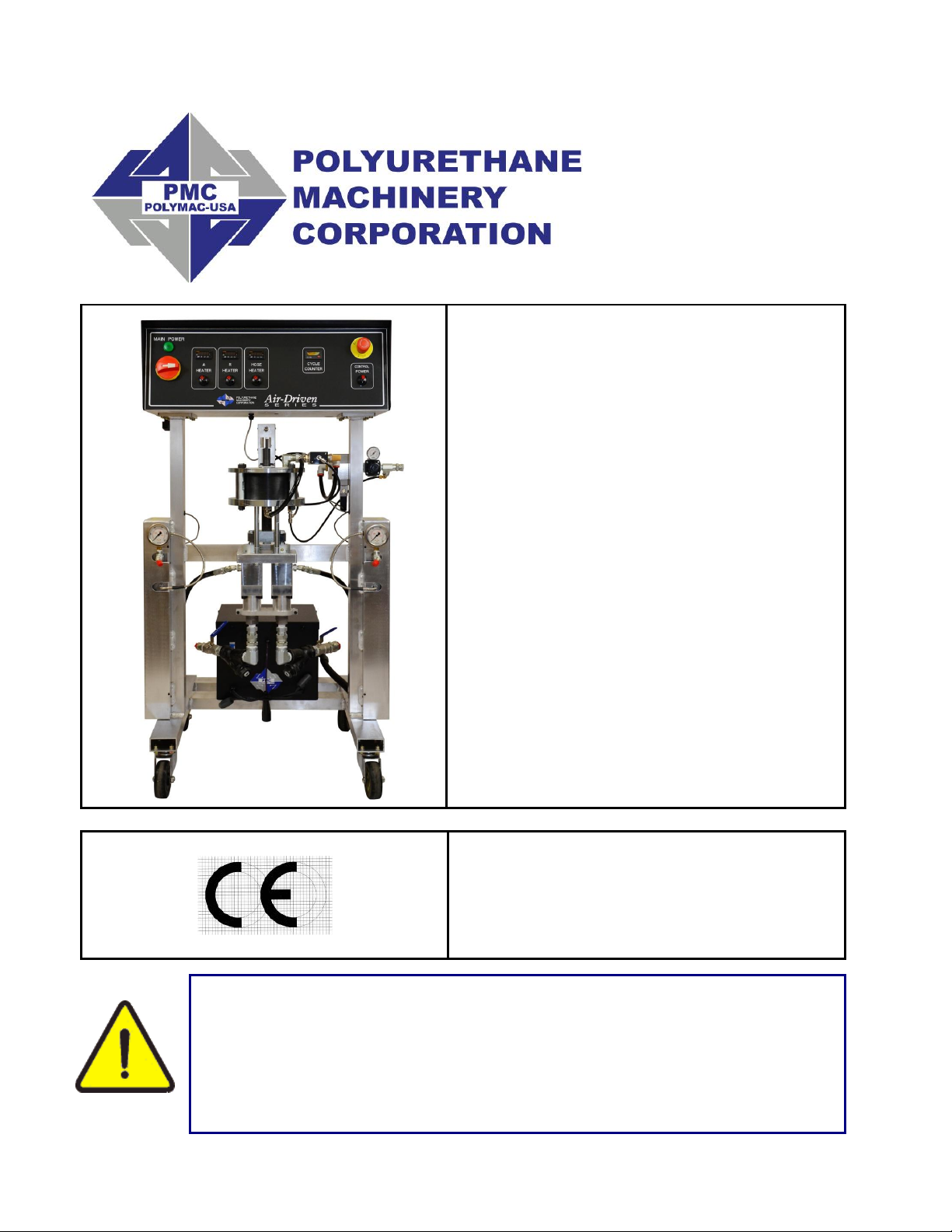
PA-25/PAX-25
Proportioners
For Professional Use Only
Not approved for use in European
explosive atmosphere locations
Electrical Diagrams
Ref. # MN-06003
REVISION 2.0
May 2, 2016
Polyurethane Machinery Corp.
Corporate: 1 KOMO Drive, Lakewood, NJ 08701
Manufacturing: 2 KOMO Drive, Lakewood, NJ 08701
Phone: 732-415-4400 Fax: 732-364-4025
http://www.polymac-usa.com
Before installing the PA Series Proportioner and start-up, carefully
read all the technical and safety documentation included in this
manual. Pay special attention to the information in order to know
and understand the operation and the conditions of use of the PA
Series Proportioner. All of the information is aimed at improving
user safety and avoiding possible breakdowns from the incorrect use
of the PA Series Proportioner.
Page 2

TABLE OF CONTENTS
WARRANTY ................................................................................................................... 1
SAFETY AND HANDLING ............................................................................................. 3
220 VAC .......................................................................................................................... 5
Component Identification ....................................................................................................................... 5
Console Assembly ................................................................................................................................ 5
Front Panel ........................................................................................................................................... 6
Bottom Plate ......................................................................................................................................... 8
Point to Point Diagrams ....................................................................................................................... 13
Incoming Power .................................................................................................................................. 13
Heater Circuit ...................................................................................................................................... 14
24VDC Power Circuit .......................................................................................................................... 15
Ladder Diagrams ................................................................................................................................... 16
Incoming Power .................................................................................................................................. 16
Heater Circuit ...................................................................................................................................... 17
24VDC Power Circuit .......................................................................................................................... 18
380 VAC ........................................................................................................................ 19
Component Identification ..................................................................................................................... 19
Console Assembly .............................................................................................................................. 19
Front Panel ......................................................................................................................................... 20
Bottom Plate ....................................................................................................................................... 22
Point to Point Diagrams ....................................................................................................................... 27
Incoming Power .................................................................................................................................. 27
Heater Circuit ...................................................................................................................................... 28
24 VDC Power Circuit ......................................................................................................................... 29
Ladder Diagrams ................................................................................................................................... 30
Incoming Power .................................................................................................................................. 30
Heater Circuit ...................................................................................................................................... 31
24 VDC Power Circuit ......................................................................................................................... 32
Page 3

WARRANTY
Polyurethane Machinery Corporation (hereinafter “PMC”) provides this LIMITED WARRANTY
(hereinafter “Warranty”) to the original purchaser (hereinafter “Customer”) covering this
equipment and the original PMC manufactured accessories delivered with the equipment
(hereinafter “Product”) against defects in material or workmanship of the Product (hereinafter
“Defect” or “Defective”) for a period of one (1) year from the date of first purchase as shown on
the original PMC invoice (hereinafter “Warranty Period”).
If during the Warranty Period under normal use, the Product is suspected by Customer to be
Defective in material or workmanship, it is Customer’s responsibility to contact PMC and return
the Product to PMC as directed by PMC, freight prepaid. If PMC determines that the Product is
Defective and that such Defect is covered by this Warranty, PMC will credit Customer for the
reasonable freight charges incurred by Customer in returning the Defective Product to PMC,
and PMC (or its authorized agent) will, at PMC’s option, repair or replace the Product, subject to
the following:
Original Invoice: The original invoice must be kept as proof of the date of first sale and the
Product serial number. The Warranty does not cover any Product if the Original Invoice
appears to have been modified or altered, or when the serial number on the Product appears to
have been altered or defaced.
Product Maintenance: It is the Customer’s responsibility to maintain the Product properly. See
your maintenance schedule and owner’s manual for details. The Warranty does not cover an
improperly maintained Product.
Non-PMC Components and Accessories: Non-PMC manufactured components and accessories
that are used in the operation of the Product are not covered by this Warranty. Such
components and accessories shall be subject to the warranty offered to the Customer, if any, by
the original manufacturer of such component or accessory.
Other Warranty Exclusions: The Warranty does not cover any Product that PMC determines has
been damaged or fails to operate properly due to misuse, negligence, abuse, carelessness,
neglect, or accident. By way of example only, this includes:
Normal wear and tear.
Improper or unauthorized installation, repair, alteration, adjustment or modification of the
Product.
Use of heating devices, pumping equipment, dispensers, or other parts or accessories
with the Product that have not been approved or manufactured by PMC.
Failure to follow the operating instructions and recommendations provided by PMC.
Cosmetic damage.
Fire, flood, “acts of God,” or other contingencies beyond the control of PMC.
1
Page 4

THE WARRANTY DESCRIBED HEREIN IS THE EXCLUSIVE REMEDY FOR THE
CUSTOMER AND IS IN LIEU OF ALL OTHER WARRANTIES, EXPRESS, IMPLIED,
STATUTORY OR OTHERWISE, AND THE IMPLIED WARRANTIES OF MERCHANTABILITY
AND FITNESS FOR A PARTICULAR PURPOSE AND ALL OTHER WARRANTIES ARE
HEREBY DISCLAIMED. TO THE FULLEST EXTENT PERMITTED BY LAW, PMC SHALL
NOT BE RESPONSIBLE, WHETHER BASED IN CONTRACT, TORT (INCLUDING, WITHOUT
LIMITATION, NEGLIGENCE), WARRANTY OR ANY OTHER LEGAL OR EQUITABLE
GROUNDS, FOR ANY CONSEQUENTIAL, INDIRECT, INCIDENTAL, LOST PROFITS,
SPECIAL, PUNITIVE OR EXEMPLARY DAMAGES, WHETHER TO PERSON OR PROPERTY,
ARISING FROM OR RELATING TO THE PRODUCT, EVEN IF PMC HAS BEEN ADVISED OF
THE POSSIBILITY OF SUCH LOSSES OR DAMAGES.
Non-Warranty Service by PMC: If PMC determines that the suspected Defect of the Product is
not covered by this Warranty, disposition of the Product will be made pursuant to the terms and
conditions of PMC’s written estimate on a time and materials basis.
Continuing Warranty for Products Repaired or Replaced under Warranty: Following the repair
or replacement of a Product covered by this Warranty, such Product will continue to be subject
to the original Warranty for the remainder of original Warranty Period or for three (3) months
from the repair or replacement date, whichever is longer.
No Rights Implied: Nothing in the sale, lease or rental of any Product by PMC shall be
construed to grant any right, interest or license in or under any patent, trademark, copyright,
trade secret or other proprietary right or material owned by anyone; nor does PMC encourage
the infringement of same.
Exclusive Warranty: This writing is the final, complete, and exclusive expression of the Warranty
covering the Product. Any statements made by PMC, its employees or agents that differ from
the terms of this Warranty shall have no effect. It is expressly understood that Customer’s
acceptance of this Warranty, by performance or otherwise, is upon and subject solely to the
terms and conditions hereof, and any additional or different terms and conditions proposed or
expressed by Customer or anyone, whether in writing or otherwise, are null and void unless
specifically agreed to in writing by an Officer of PMC.
2
Page 5

SAFETY AND HANDLING
This chapter contains important information on the safety, handling and use of your PH Series
Console.
Before performing maintenance and starting up the PH Series Console, carefully read and
comprehend all the technical and safety information included in this manual. The information is
aimed at enhancing user safety and avoiding possible breakdowns caused by incorrect or
improper use.
Always disconnect the console from the main power source before opening the
console.
WARNING! Presents information to alert of a situation that might cause
serious injuries if the instructions are not followed.
CAUTION Presents information that indicates how to avoid damage to the
Proportioner or how to avoid a situation that could cause minor injuries.
NOTE! Is relevant information of a procedure being carried out.
Careful study of this manual will enable the operator to understand the characteristics of the PH
Series Console and the operating procedures. By following the instructions and
recommendations contained herein, you will reduce the potential risk of accidents in the
installation, use, or maintenance of the PH Series Console. You will also provide a better
opportunity for increased output, incident-free operation for a longer time, and the possibility of
detecting and resolving problems fast and simply.
Keep this Operations Manual for future consultation of useful information at all times. If you lose
this manual, ask for a new copy from your PMC authorized distributor or go online at our web
site (www.polymac-usa.com).
3
Page 6
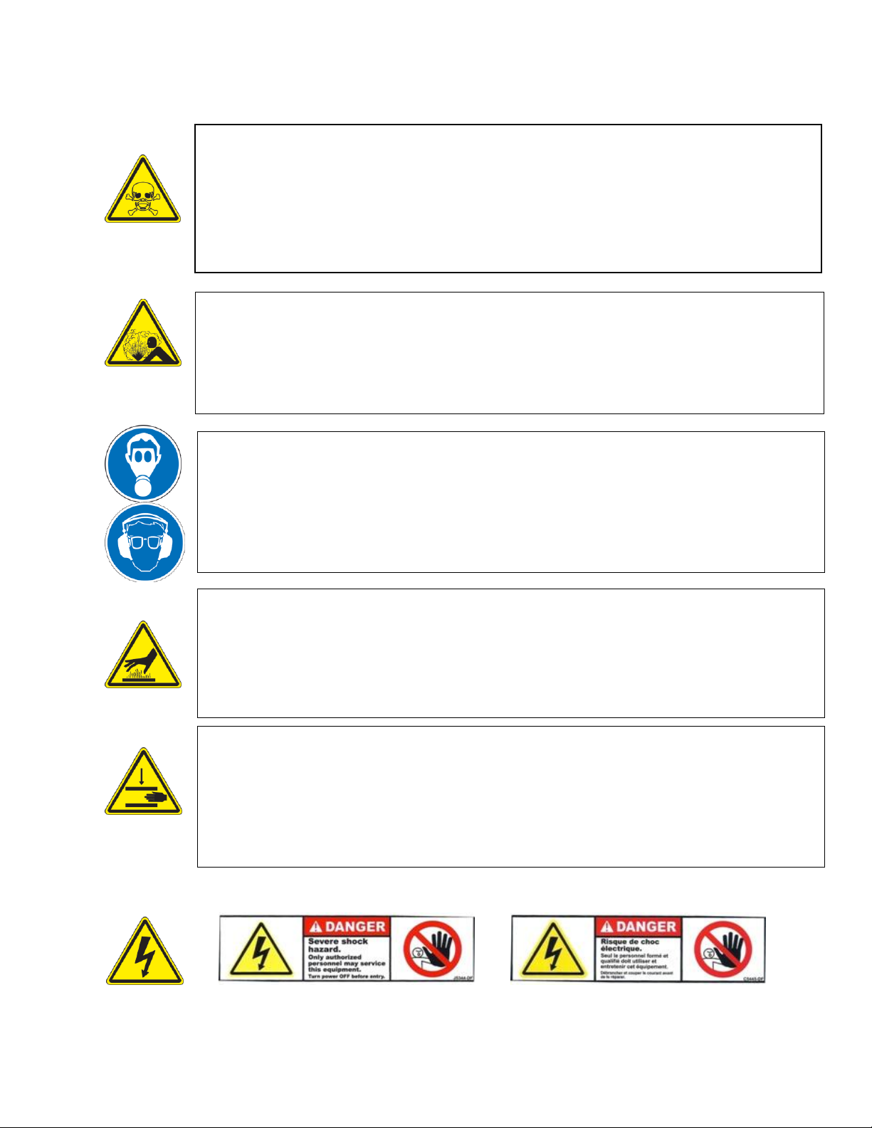
To prevent possible injury caused by incorrect handling of the raw materials and
solvents used in the process, carefully read the Material Safety Data Sheet
(MSDS) provided by your supplier.
Deal with waste caused according to current regulations.
Pour éviter toute blessure causée par une mauvaise manipulation des matières
premières et les solvants utilisés dans le processus, veuillez lire attentivement
la fiche signalétique (MSDS) fournies par votre fournisseur.
To avoid damage caused by the impact of pressurized fluids, do not open any
connection or perform maintenance work on the components subject to pressure
until the pressure has been completely eliminated.
Pour éviter les dommages causés par l'impact des fluides sous pression, ne pas
ouvrir un lien ou d'effectuer des travaux d'entretien sur les éléments soumis à la
pression jusqu'à ce que la pression a été complètement éliminé.
Use suitable protection when operating, maintaining or being present in the area
where the equipment is functioning. This includes, but is not limited to, the use of
protective goggles, gloves, shoes and safety clothing and breathing equipment.
Utiliser une protection appropriée utilisation, d'entretien ou d'être présents dans
la région où le matériel fonctionne. Cela inclut, mais n'est pas limité à, l'utilisation
de lunettes de protection, gants, chaussures et vêtements de sécurité et un
équipement respiratoire.
The equipment includes components that reach high temperatures and can
cause burns. Hot parts of the equipment must NOT be handled or touched until
they have cooled completely.
L'équipement comprend des éléments qui atteignent des températures élevées
et peuvent provoquer des brûlures. Les parties chaudes de l'équipement ne doit
pas être manipulé ou touché jusqu'à ce qu'ils aient complètement refroidi.
To prevent serious injury through crushing or amputation, do not work with the
equipment without the safety guards installed on the moving parts. Make sure
that all the safety guards are correctly reinstalled at the end of the repair or
maintenance work of the equipment.
L'équipement comprend des éléments qui atteignent des températures élevées
et peuvent provoquer des brûlures. Les parties chaudes de l'équipement ne doit
pas être manipulé ou touché jusqu'à ce qu'ils aient complètement refroidi.
4
Page 7
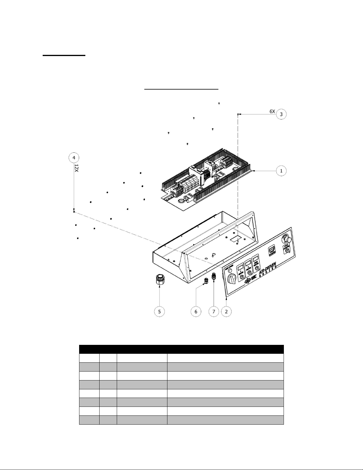
220 VAC
CONSOLE ASSEMBLY
ITEM
QTY
PART NUMBER
DESCRIPTION
1 1 -
BOTTOM PLATE (SEE PAGE 8)
2 1 -
FRONT PANEL (SEE PAGE 6)
3 6 -
#8-32 X 3/8 CROSS RECESSED PAN HEAD
4
12 - #8-32 SERRATED WASHER
5 1 EL-00088-01A
HEYCO SR INCOMING POWER
6 1 EL-000P12
HEYCO #6 AWG STRAIN RELIEF
7 1 EL-000P13
STRAIN RELIEF
Component Identification
Console Assembly
5
Page 8
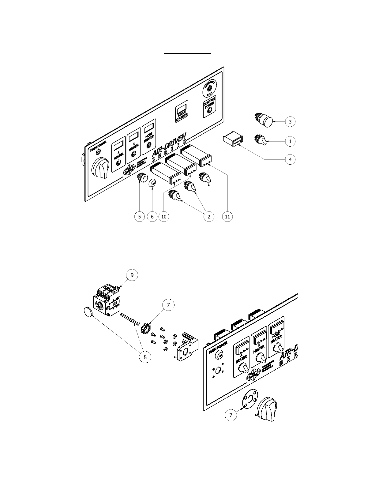
Front Panel
6
Page 9
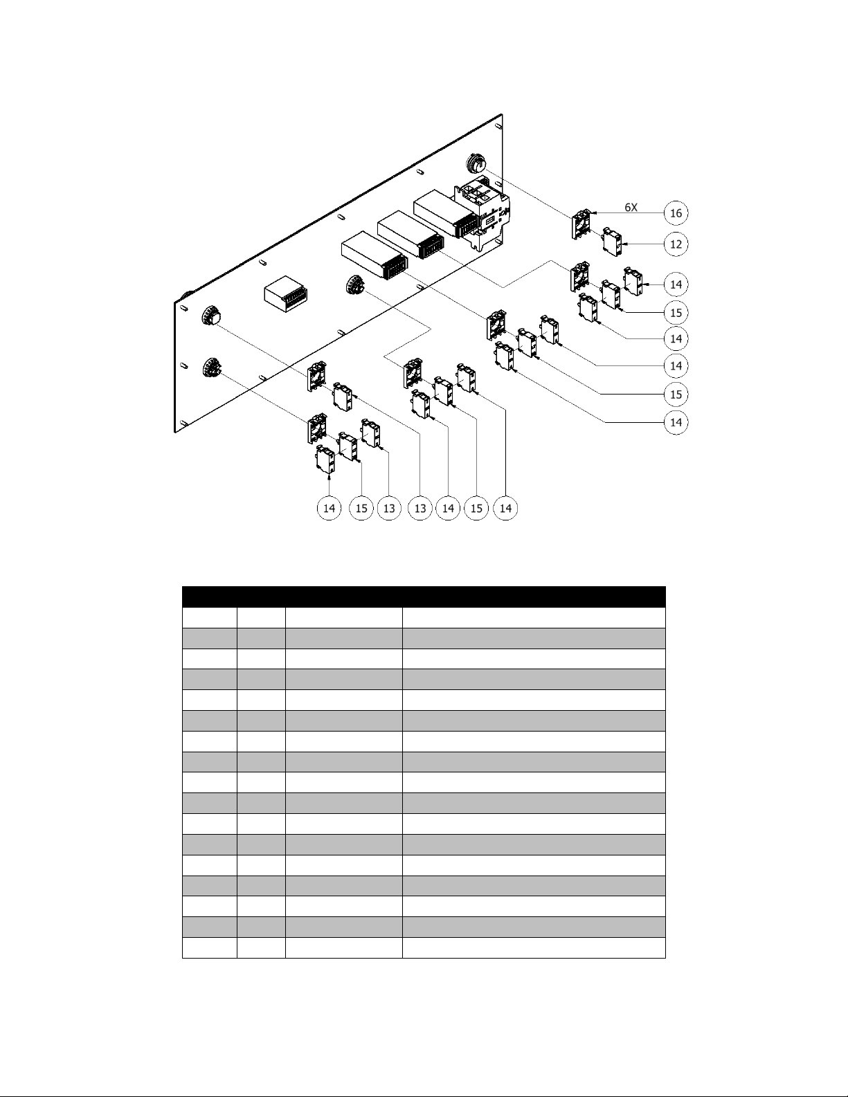
FRONT PANEL COMPONENTS
ITEM
QTY
PART NUMBER
DESCRIPTION
1 1 EL-128-R
SELECTOR SWITCH; 3 POS; RED
2 3 EL-129-R
SELECTOR SWITCH; RED
3 1 EL-107
E-STOP PUSH-TWIST
4 1 EL-124
TOTALIZER; BATT OP
5 1 EL-134
LIGHT SWITCH
6 1 EL-135
GREEN LENS; "ON"
7 1 EL-105
SELECTOR HANDLE; RED
8 1 EL-103
DOOR MOUNTING KIT
9 1 EL-100
ROTARY DISCONNECT; 80A; 3 POLE
10 2 EL-159-HTR
TEMPERATURE CONTROLLER; PRE-HTR
11 1 EL-159-H
TEMPERATURE CONTROLLER; HOSE
12 1 EL-132-G
GREEN LIGHT UNIT
13 2 EL-133-NC
CONTACT BLOCK; NC
14 7 EL-133-NO
CONTACT BLOCK; NO
15 4 EL-131-R
LIGHT UNIT; RED; 24VDC
16 6 -
MOUNTING ADAPTER
7
Page 10
Bottom Plate
8
Page 11
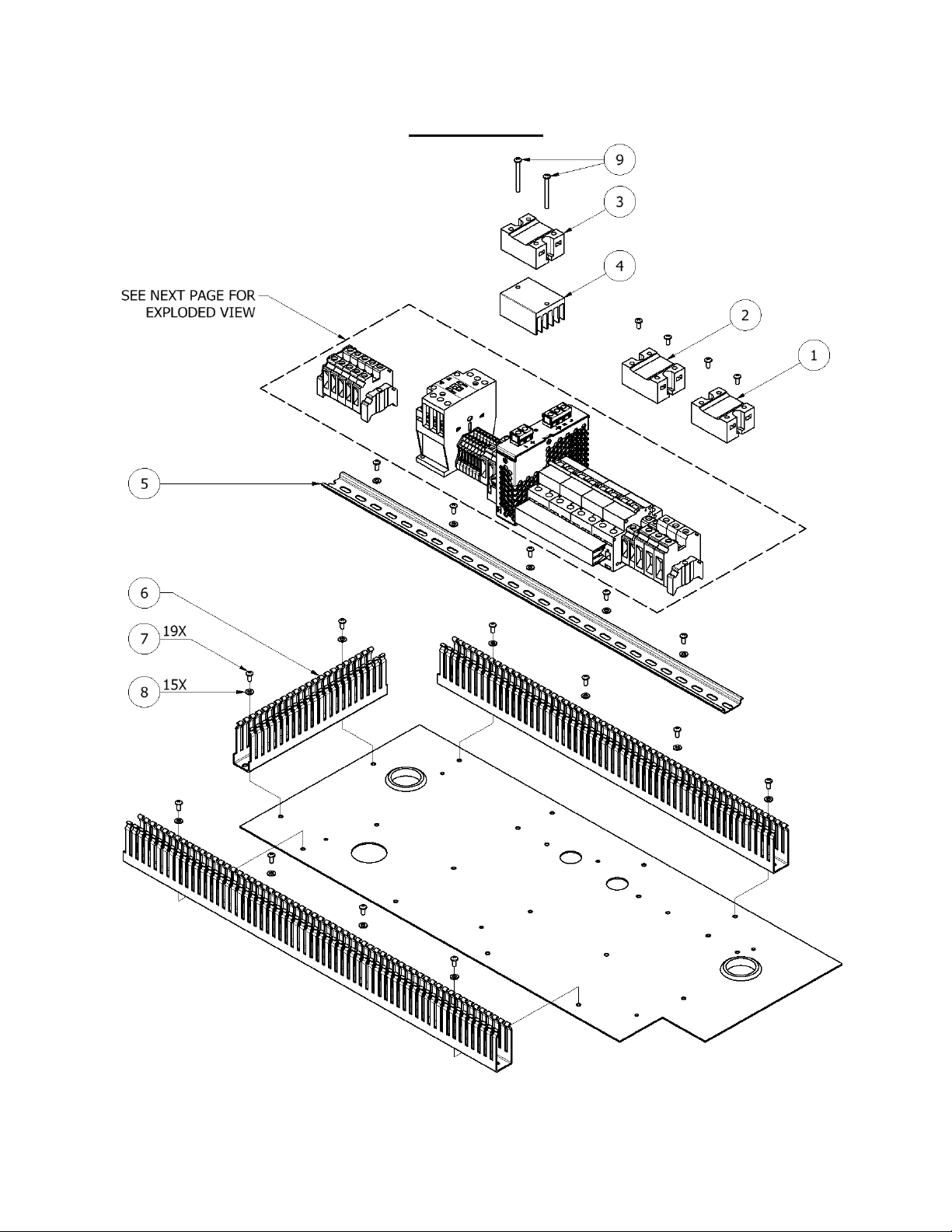
BOTTOM PLATE COMPONENTS
ITEM
QTY
PART NUMBER
DESCRIPTION
LABEL
1 1 EL-34
RELAY; 50 AMP; 480V
SSR1 A-HTR
2 1 EL-34
RELAY; 50 AMP; 480V
SSR2 R-HTR
3 1 EL-35
RELAY; HOSE HEAT
SSR3 HOSE
4 1 EL-35-1
HEAT SINK
-
5 2 EL-147
DIN RAIL; 35 X 7.5 MM
-
6 5 EL-149
WIRE DUCT 1.0 X 2.25
-
7
19 - CROSS RECESSED PAN HEAD #8-32 X 3/8
-
8
15
-
#8 PLAIN WASHER
-
9 2 -
CROSS RECESSED PAN HEAD #8-32 X 1-3/4
-
A 1 -
SEE PAGE 10
-
B 1 -
SEE PAGE 11
-
C 1 -
SEE PAGE 12
-
9
Page 12

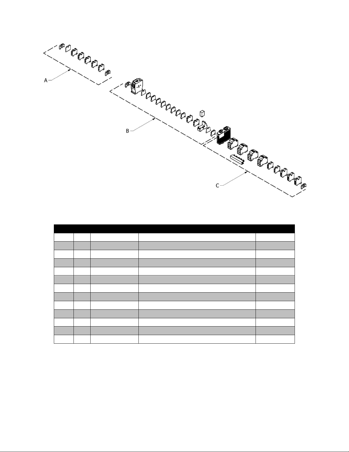
BOTTOM PLATE COMPONENTS
ITEM
QTY
PART NUMBER
DESCRIPTION
LABEL
1 2 EL-152
END STOP; 35MM
- 2 1
EL-156
END COVERS; 12MM TERM BLOCKS
- 3 1
EL-145
12MM GROUND BLOCK 15-4 AWG
GRD 9 1
EL-141
TERMINAL BLOCK; 10.2MM
9
11 1 EL-141
TERMINAL BLOCK; 10.2MM
11
14 1 EL-141
TERMINAL BLOCK; 10.2MM
14
15 1 EL-141
TERMINAL BLOCK; 10.2MM
15
Detail A
10
Page 13

BOTTOM PLATE COMPONENTS
ITEM
QTY
PART NUMBER
DESCRIPTION
LABEL
1 1 EL-152
END STOP; 35MM
-
2 1 EL-118
CONTACTOR; 32A; 24VDC COIL
M1 3 1
EL-140
TERMINAL BLOCK; 5.2MM
3 4 1
EL-140
TERMINAL BLOCK; 5.2MM
4 5 1
EL-140
TERMINAL BLOCK; 5.2MM
5 6 1
EL-140
TERMINAL BLOCK; 5.2MM
6
7 1 EL-140
TERMINAL BLOCK; 5.2MM
7
8 1 EL-140
TERMINAL BLOCK; 5.2MM
8
9 1 EL-140
TERMINAL BLOCK; 5.2MM
9
10 1 EL-140
TERMINAL BLOCK; 5.2MM
10
11 2 EL-156-10
TERMINAL COVER; 10MM/5.2MM
-
12 1 EL-121
RELAY SOCKET
-
13 1 EL-144
TERMINAL BLOCK; 5.2MM; GRND
GRD
14 1 EL-120
DPDT RELAY; 24VDC COIL
MCR
107 1 EL-142
TERMINAL BLOCK; 12MM
107
200 1 EL-142
TERMINAL BLOCK; 12MM
200
Detail B
11
Page 14

Detail C
BOTTOM PLATE COMPONENTS
ITEM
QTY
PART
NUMBER
DESCRIPTION
LABEL
1 1 EL-116
CIRCUIT BREAKER; 25A, 2 POLE; TYPE UL1077
CB1 A-HTR
2 1 EL-116
CIRCUIT BREAKER; 25A, 2 POLE TYPE UL1077
CB1 R-HTR
3 1 EL-115
CIRCUIT BREAKER; 15A, 2 POLE TYPE UL1077
CB3 HOSE
4
1
EL-114
CIRCUIT BREAKER; 3A, 2 POLE TYPE UL1077
CB4 CNTL
5 1 EL-142
TERMINAL BLOCK; 12MM
5
6 1 EL-152
END STOP; 35MM
-
7 1 EL-142
TERMINAL BLOCK; 12MM
7
8 1 EL-146
TERMINAL BLOCK; 16MM; GRND
GRD
9 1 EL-122
POWER SUPPLY; 2.5A; 230VAC/24VDC
PS
10 1 EL-151
JUMPER STRIP
-
11 1 EL-143
TERMINAL BLOCKL; 16MM
L1
12 1 EL-143
TERMINAL BLOCKL; 16MM
L2
12
Page 15

Point to Point Diagrams
Incoming Power
13
Page 16

Heater Circuit
14
Page 17

24VDC Power Circuit
15
Page 18

Ladder Diagrams
12
RD
34
21
CB1
3 4
21
CB2
3 4
21
CB3
3 4
21
CB4
3 4
POWER LT
R
L1
L2
GRD
L1
L1
1
2
2
1
2
1
1
2
1
2
2
1
Incoming Power
16
Page 19

Heater Circuit
3 4
3 4
A-HTR
L1T1
SSR1
R-HTR
T2L2
M1
L2T2
SSR2
L3T3
M1
ICL
15A
142021
60
110
160
210
260
310
HOSE
L1T1
SSR3
VOLTR
AMP
W
"A" TEMPERATURE CONTROLLER
1 2 5 6 9 10
"R" OVERTEMP "A" OVERTEMP
A2A1
M1
M1 CONTACTOR
POWER SUPPLY
L
N
G
"R" TEMPERATURE CONTROLLER
1 2 5 6 9 10
HOSE TEMPERATURE CONTROLLER
1 2 5 6 9 10
T1L1
M1
3 4
A-HTR SWITCH
3 4
R-HTR SWITCH
3 4
HOSE-HTR SWITCH
1411
CONTACT
200
CB
21
CB4
21
CB3
21
CB2
21
CB1
3 4
3 4
107 107 3 4 2005250 50 52
5
7
9 11
15
14
15A15
14
5 75 7 8
6
9 11 12
10
13
14
15
9 11
14
15A
21
20
18
19
18
19
18
19
18
18
19
18
31
34
37
MCR*
TC TC TC
A2
A1
SSR1
A2
A1
SSR2
A2
A1
SSR3
30
32
33
36
35
38
*See 24 VDC Power Circuit on page 18 for complete MCR wiring
17
Page 20

4 3
CONTROL POWER
4441
MCR - NO
1 2
CONTROL POWER
2 1
E-STOP
107
"R" PRESSURE SWITCH
4 3
HOSE-HTR SWITCH
4 3
R-HTR SWITCH
4 3
A-HTR SWITCH
X2X1
HOSE LIGHT
R
X2X1
R-HTR LIGHT
R
X2X1
A-HTR LIGHT
R
X2X1
CONTROL POWER LIGHT
R
A2A1
MCR - COIL
POWER SUPPLY
+
"A" PRESSURE SWITCH
SOLENOID
5
8
102
200
200
200
200
200
107
54555656
200
200
200
200
107
107
200
100
102
CYCLE COUNTER
2 4
6
10
COUNTER SWITCH
3
1
101
101
100
MCR
200
5858
200
200
102 102
24VDC Power Circuit
18
Page 21

380 VAC
CONSOLE ASSEMBLY
ITEM
QTY
PART NUMBER
DESCRIPTION
1 1 -
BOTTOM PLATE (SEE PAGE 22)
2 1 -
FRONT PANEL (SEE PAGE 20)
3 6 -
#8-32 X 3/8 CROSS RECESSED PAN HEAD
4
12 - #8-32 SERRATED WASHER
5 1 EL-00088-01A
HEYCO SR INCOMING POWER
6 1 EL-000P12
HEYCO #6 AWG STRAIN RELIEF
7 1 EL-000P13
STRAIN RELIEF
Component Identification
Console Assembly
19
Page 22

Front Panel
20
Page 23

FRONT PANEL COMPONENTS
ITEM
QTY
PART NUMBER
DESCRIPTION
1 1 EL-128-R
SELECTOR SWITCH; 3 POS; RED
2 3 EL-129-R
SELECTOR SWITCH; RED
3 1 EL-107
E-STOP PUSH-TWIST
4 1 EL-124
TOTALIZER; BATT OP
5 1 EL-134
LIGHT SWITCH
6 1 EL-135
GREEN LENS; "ON"
7 1 EL-105
SELECTOR HANDLE; RED
8 1 EL-103
DOOR MOUNTING KIT
9 1 EL-100
ROTARY DISCONNECT; 80A; 3 POLE
10 2 EL-159-HTR
TEMPERATURE CONTROLLER; PRE-HTR
11 1 EL-159-H
TEMPERATURE CONTROLLER; HOSE
12 1 EL-132-G
GREEN LIGHT UNIT
13 2 EL-133-NC
CONTACT BLOCK; NC
14 7 EL-133-NO
CONTACT BLOCK; NO
15 4 EL-131-R
LIGHT UNIT; RED; 24VDC
16 6 -
MOUNTING ADAPTER
21
Page 24

Bottom Plate
22
Page 25

BOTTOM PLATE COMPONENTS
ITEM
QTY
PART NUMBER
DESCRIPTION
LABEL
1 1 EL-34
RELAY; 50 AMP; 480V
SSR1 A-HTR
2 1 EL-34
RELAY; 50 AMP; 480V
SSR2 R-HTR
3 1 EL-35
RELAY; HOSE HEAT
SSR3 HOSE
4 1 EL-35-1
HEAT SINK
-
5 2 EL-147
DIN RAIL; 35 X 7.5 MM
-
6 5 EL-149
WIRE DUCT 1.0 X 2.25
-
7
19 - CROSS RECESSED PAN HEAD #8-32 X 3/8
-
8
15
-
#8 PLAIN WASHER
-
9 2 -
CROSS RECESSED PAN HEAD #8-32 X 1-3/4
-
A 1 -
SEE PAGE 24
-
B 1 -
SEE PAGE 25
-
C 1 -
SEE PAGE 26
-
23
Page 26

BOTTOM PLATE COMPONENTS
ITEM
QTY
PART NUMBER
DESCRIPTION
LABEL
1 2 EL-152
END STOP; 35MM
- 2 1
EL-156
END COVERS; 12MM TERM BLOCKS
- 3 1
EL-145
12MM GROUND BLOCK 15-4 AWG
GRD 9 1
EL-141
TERMINAL BLOCK; 10.2MM
N
11 1 EL-141
TERMINAL BLOCK; 10.2MM
11
14 1 EL-141
TERMINAL BLOCK; 10.2MM
N
15 1 EL-141
TERMINAL BLOCK; 10.2MM
15
Detail A
24
Page 27

Detail B
BOTTOM PLATE COMPONENTS
ITEM
QTY
PART NUMBER
DESCRIPTION
LABEL
1 2 EL-152
END STOP; 35MM
- 2 1
EL-118
CONTACTOR; 32A; 24VDC COIL
M1 3 1
EL-140
TERMINAL BLOCK; 5.2MM
3
4 1 EL-140
TERMINAL BLOCK; 5.2MM
4
5 1 EL-140
TERMINAL BLOCK; 5.2MM
5 6 1
EL-140
TERMINAL BLOCK; 5.2MM
6 7 1
EL-140
TERMINAL BLOCK; 5.2MM
7 8 1
EL-140
TERMINAL BLOCK; 5.2MM
8 9 1
EL-140
TERMINAL BLOCK; 5.2MM
9
10 1 EL-140
TERMINAL BLOCK; 5.2MM
10
11 2 EL-156-10
TERMINAL COVER; 10MM/5.2MM
-
12 1 EL-121
RELAY SOCKET
-
13 1 EL-144
TERMINAL BLOCK; 5.2MM; GRND
GRD
14 1 EL-120
DPDT RELAY; 24VDC COIL
MCR
15 1 EL-122
POWER SUPPLY; 2.5A; 230VAC/24VDC
PS
107 1 EL-142
TERMINAL BLOCK; 12MM
107
200 1 EL-142
TERMINAL BLOCK; 12MM
200
25
Page 28

Detail C
BOTTOM PLATE COMPONENTS
ITEM
QTY
PART NUMBER
DESCRIPTION
LABEL
1
1
EL-191
CIRCUIT BREAKER; 32A; 1 POLE
CB1 A-HTR
2
1
EL-191
CIRCUIT BREAKER; 32A; 1 POLE
CB1 R-HTR
3
1
EL-191
CIRCUIT BREAKER; 32A; 1 POLE
CB3 HOSE
4
1
EL-186
SINGLE POLE; 3 AMP BREAKER
CB4 CNTL
5 1 EL-146
TERMINAL BLOCK; 16MM; GRND
GRD
6 2 EL-152
END STOP; 35MM
-
7 1 EL-142
TERMINAL BLOCK; 12MM
7
8
1
El-143
TERMINAL BLOCKL; 16MM
L1
9 1 El-143
TERMINAL BLOCKL; 16MM
L2
10 1 El-143
TERMINAL BLOCKL; 16MM
L3
11 1 EL-143
TERMINAL BLOCKL; 16MM
N
12 1 EL-143
TERMINAL BLOCKL; 16MM
N
26
Page 29

Point to Point Diagrams
*See Heater Circuit on page 28.
Incoming Power
27
Page 30

*See Incoming Power on page 27.
Heater Circuit
28
Page 31

24 VDC Power Circuit
29
Page 32

31
CB1
31
CB3
12
RD
34
56
31
CB2
31
CB4
POWER LT
R
L1
L2
L3
GRD
L1
L2
L3
1
2
3 3
3
1
1 N
TO HOSE HEAT
CONTROLLER*
*See Heater Circuit on page 31.
Ladder Diagrams
Incoming Power
30
Page 33

Heater Circuit
L2T2M1T3L3
M1
INRUSH CURRENT LIMITER
15A
N
20
21
60
110
160
210
260
310
HOSE
L1T1
SSR3
AMP
W
"A" TEMPERATURE CONTROLLER
1 2 5 6 9 10
"R" OVERTEMP "A" OVERTEMP
A2A1
M1
M1 CONTACTOR
POWER SUPPLY
L
N
G
"R" TEMP ERATURE CONTROLLER
1 2 5 6 9 10
HOSE TEMPERATURE CONTROLLER
1 2 5 6 9 10
L1T1
M1
200
CB
21
CB4
21
CB3
21
CB2
21
CB1
107 107 3 4 2005250 50 52
15
15
21
T1L1
SSR1
A-HTR
L2T2
SSR2
R-HTR
7 N
11 N
N
VOLTR
15A 15A
1411
CONTACT
6
8
7
10 12 11
1513
18 18
18
18
18
N
N
N
N
N
N
N
20
18
MCR*
TO MAIN
DISCONNECT**
X1
X2
MAIN POWERG
1
TC TC TC
3 4
A-HTR SWITCH
3 4
R-HTR SWITCH
3 4
HOSE-HTR SWITCH
31
34
37
A2
A1
SSR1
A2
A1
SSR2
A2
A1
SSR3
30
32
33
36
35
38
*See 24 VDC Power Circuit on page 32 for complete MCR wiring
**See Incoming Power on page 30.
31
Page 34

4 3
CONTROL POWER
4441
MCR - NO
1 2
CONTROL POWER
2 1
E-STOP
107
"R" PRESSURE SWITCH
4 3
HOSE-HTR SWITCH
4 3
R-HTR SWITCH
4 3
A-HTR SWITCH
X2X1
HOSE LIGHT
R
X2X1
R-HTR LIGHT
R
X2X1
A-HTR LIGHT
R
X2X1
CONTROL POWER LIGHT
R
A2A1
MCR - COIL
POWER SUPPLY
+
"A" PRESSURE SWITCH
SOLENOID
5
8
102
200
200
200
200
200
107
54555656
200
200
200
200
107
107
200
100
102
CYCLE COUNTER
2 4
6
10
COUNTER SWITCH
3
1
101
101
100
MCR
200
5858
200
200
102 102
24 VDC Power Circuit
32
 Loading...