

Page 1

Thyristor-Power Controller
PMA-Relay S 3PH
from 60A to 210A
User Manual
PMA-S3-60-210A
Valid from: 30.06.2019 Order number: 9499-040-96711
Page 2

PMA-Relay S 3PH from 60A to 210A
A publication of:
PMA
Prozeß- und Maschinen-Automation GmbH
P.O.Box 310 229 • D-34058 Kassel • Germany
All rights reserved.
No part of this document may be reproduced or published in any form or by any means
without prior written permission from the copyright owner.
Liability and warranty
Any information and notes in these operating instructions were composed under consideration
of the applicable regulations, the present state of the art and our extensive know-how and
experience.
With special versions, additional ordering options or due to the latest technical modifications,
the actual scope of delivery may vary from the descriptions and drawings in this manual.
For questions, please, contact the manufacturer.
Before starting to work with the instrument and before commissioning, in particular,
these operating instructions must be read carefully! The manufacturer cannot be held
responsible for damage and trouble resulting from failure to comply with the
information given in this manual.
This product may be subject to change due to improvements of the product features in
the course of further development.
Copyright
This operating manual should be considered as confidential information, intended only for
persons who work with the instrument.
Contraventions are subject to payment of damages. Further claims reserved.
2 User Manual
Page 3

PMA-Relay S 3PH from 60A to 210A
Inhalt
1. Important warnings for safety .............................................................................................. 4
1.1. Safety notes .......................................................................................................................... 4
2. Maintenance ......................................................................................................................... 6
3. Basic Connections ................................................................................................................. 7
4. Identification and Order Code .............................................................................................. 8
4.1. Identification of the unit ...................................................................................................... 8
5. Order Code ........................................................................................................................... 9
6. Technical Specifications ...................................................................................................... 10
6.1. General features ................................................................................................................. 10
6.2. Input features ..................................................................................................................... 10
6.3. Output features (power device) ......................................................................................... 10
6.4. Fan Specification (60 to 90A) .............................................................................................. 10
6.5. Fan Specification (120 to 210A) .......................................................................................... 10
6.6. Environmental installation conditions ............................................................................... 11
6.7. Derating Curve .................................................................................................................... 11
7. Installation .......................................................................................................................... 12
7.1. Dimensions and weight ...................................................................................................... 12
7.2. Fixing holes ......................................................................................................................... 13
8. Wiring instructions ............................................................................................................. 14
8.1. Terminals Positions 3PH 60-90A Size ................................................................................. 14
8.2. Terminals Positions 3PH 120-210A Size ............................................................................. 15
8.3. Power Terminals ................................................................................................................. 15
8.4. Command Terminals .......................................................................................................... 16
8.4.1. Terminal block M1 for SSR Input ........................................................................................ 16
8.4.2. Terminal block M1 for Analog Input or SSR input with HB ................................................ 16
8.5. Connection Diagram for 3 phases (control on 3 phases) from 60 to 90A .......................... 17
8.6. Connection Diagram for 3 phases (control on 2 phases) from 120 to 210A ...................... 18
8.7. Led status and alarms ......................................................................................................... 19
9. Heater Break alarm and SCR short circuit (HB Option only) ............................................. 19
9.1. Heater break Calibration procedure .................................................................................. 19
9.2. HB Alarm contact ................................................................................................................ 20
10. Input setting ....................................................................................................................... 21
10.1. Input calibration procedure ............................................................................................... 22
11. Firing type ........................................................................................................................... 23
11.1. Zero Crossing (ZC) with SSR Input ...................................................................................... 23
11.2. Burst Firing (BF) with Analog Input .................................................................................... 23
11.3. Burst Firing settings ............................................................................................................ 24
12. Internal Fuse ....................................................................................................................... 25
12.1. Fuses Replacement ............................................................................................................. 26
13. Trouble shooting ................................................................................................................ 27
Important warnings for safety 3
Page 4

PMA-Relay S 3PH from 60A to 210A
This icon i
s present in all the operational procedures where the Improper operation
Warning or Hazard that needs further explanation than the label on unit can provide.
If available, unit is a Listed device per Underwriters Laboratories. It has been
ESD Sensitive product, use proper grounding and handling techniques when installing
Do not throw in trash, use proper recycling techniques or consult manufacturer for
1. Important warnings for safety
This chapter contains important information for the safety. The not observance of these
instructions may result in serious personal injury or death and can cause serious damages to the
Thyristor unit and to the components system included.
The installation should be performed by qualified persons.
In the manual are used symbols to give more evidence at the notes of safety and operativity for
the attention for the user:
may result in serious personal injury or death by Electrical Shock Hazard Symbol
(a lightning bolt in a triangle) precedes an electric shock hazard CAUTION or WARNING
safety statement.
Consult User’s Guide for further information.
Unit is compliant with European Union directives. See Declaration of Conformity for
further details on Directives and Standards used for Compliance.
investigated to ANSI/UL® 508 standards for Industrial Control Switches and equivalent
to CSA C22.2 #14. For more detail search for File E505847 on www.ul.com
or servicing product.
proper disposal.
A “NOTE” marks a short message to alert you to an important detail.
A “CAUTION” safety alert appears with information that is important for protecting your
equipment and
performance. Be especially careful to read and follow all cautions that apply to your application.
A “WARNING” safety alert appears with information that is important for protecting you, others
and equipment
from damage. Pay very close attention to all warnings that apply to your application.
1.1. Safety notes
WARNING! To avoid damage to property and equipment, injury and loss of life, adhere to applicable
electrical codes and standard wiring practices when installing and operating this product. Failure to do
so could result in damage, injury and death.
WARNING! All service including inspection, installation, wiring, maintenance, troubleshooting, fuse
or other user serviceable component replacement must be performed only by properly qualified
personnel. Service personnel must read this manual before proceeding with work. While service is
being performed unqualified personnel should not work on the unit or be allowed in the immediate
vicinity.
WARNING! When in use the power controller is connected to dangerous voltages. Do not remove the
protective covers without first disconnecting and preventing power from being restored while servicing
the unit.
WARNING! Do not use in aerospace or nuclear applications.
4 User Manual
Page 5
PMA-Relay S 3PH from 60A to 210A
WARNING! The power controller’s protection rating is IP20 with all covers installed and closed. It must
be installed in an enclosure that provides all the necessary additional protections appropriate for the
environment and application.
WARNING! Ground the power controller via the provided protective earth grounding terminal. Verify
ground is within impedance specifications. This should be verified periodically.
WARNING! Electric Shock Hazard: when the power controller has been energized, after shutting off the
power, wait at least one minute for internal capacitors to discharge before commencing work that brings
you in to contact with power connections or internal components.
WARNING! The installation must be protected by electromagnetic circuit breakers or by fuses. The
semiconductor fuses located inside the power controller are classified for UL as supplementary
protection for semiconductor devices. They are not approved for branch circuit protection.
WARNING! When making live voltage or current measurements, use proper personal protective
equipment for the voltages and arc-flash potentials involved.
WARNING! Verify the voltage and current ratings of the power controller are correct for the application.
CAUTION: To avoid compromising the insulation, do not bend wire or other components beyond their
bend radius specifications.
CAUTION: Protect the power controller from high temperature, humidity and vibrations.
CAUTION: The power controller warranty is void if the tested and approved fuses are not used.
CAUTION: Only trained and authorized personnel should access and handle the internal electronics and
they must follow proper electro-static prevention procedures.
CAUTION: Install an appropriately sized RC filter across contactor coils, relays and other inductive
loads.
CAUTION: The thyristor units here described have been designed for use with sinusoidal networks with
nominal frequency 50-60 Hz. Any application with NON-SINUSOIDAL, distorted or disturbed networks
could compromise the correct operation of the unit.
NOTE: Provide a local disconnect to isolate the power controller for servicing.
NOTE: The nominal current is specified for ambient temperatures at or below 40° C. Ensure the application
design allows for adequate cooling of each power controller. The power controller must be mounted
vertically. The cooling design must prevent air heated by one power controller from causing power
controllers mounted above to exceed the ambient operating temperature limit. When power controllers
are mounted side by side allow a minimum spacing of 15mm between them.
NOTE: Use only copper cables and wires rated for use at 75°C or greater.
Important warnings for safety 5
Page 6

PMA-Relay S 3PH from 60A to 210A
2. Maintenance
In order to have a corrected cooling, the user must clean the heat-sink and the protective grill of
the fans.
The frequency of this servicing depends on environmental pollution.
Also check periodically if the screw for the power cables and safety earth are tightened correctly
(See Connection Diagram)
6 User Manual
Page 7
PMA-Relay S 3PH from 60A to 210A
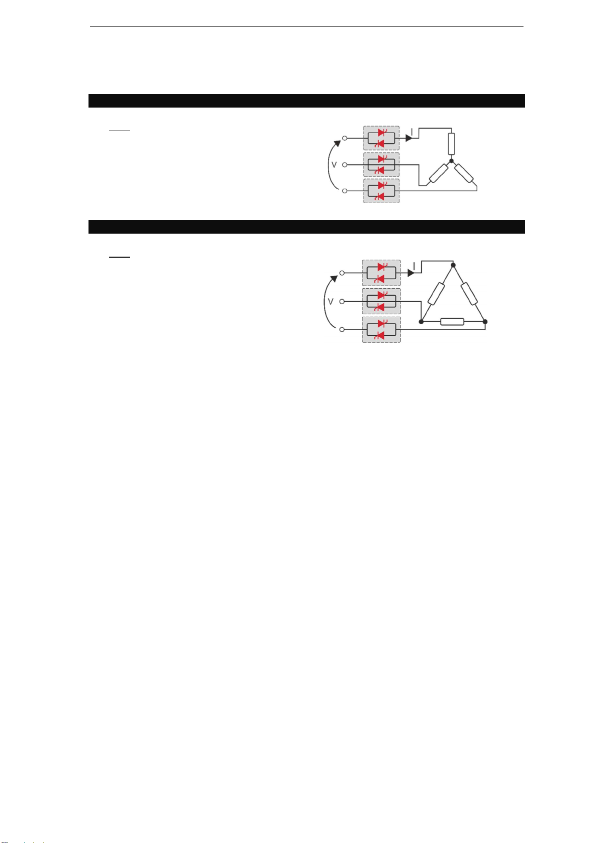
3. Basic Connections
Star wiring with resistive load (control on three phases)
𝐼 =
V = Nominal voltage of the load
I = Nominal current of the load
P = Nominal power of the load
Delta wiring with resistive load (control on three phases)
𝐼 =
V = Nominal voltage of the load
I = Nominal current of the load
P = Nominal power of the load
.
.
Basic Connections 7
Page 8
PMA-Relay S 3PH from 60A to 210A
4. Identification and Order Code
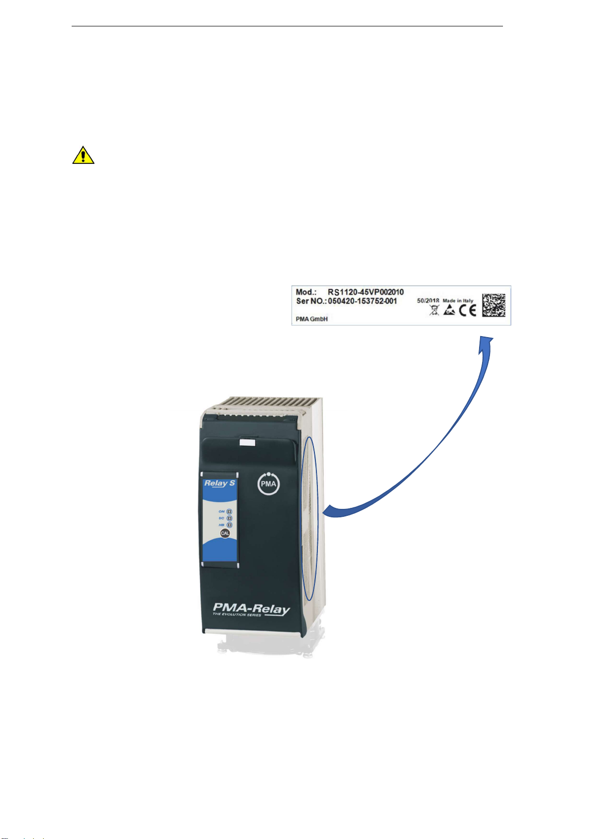
4.1. Identification of the unit
Caution: Before to install, make sure that the Thyristor unit have not damages. If the
product has a fault, please contact the dealer from which you purchased the product.
The identification label give all the information regarding the factory settings of the Thyristor
unit, this label is on the unit, like represented in figure.
Verify that the product is the same thing as ordered.
8 User Manual
Page 9
PMA-Relay S 3PH from 60A to 210A
90 A 0 9 0
120 A 1 2 0
150 A 1 5 0
180 A 1 8 0
Aux. Voltage Supply
No Aux. Voltage without HB and/or Analog Input
0 With HB and/or Analog Input 12:24V ac
-dc 4
Input signal
(SSR)
S
0:10 V dc V 4:20 mA A Firing
ZC Zero Crossing
Z Burst Firing 4 Cycles On at 50% Power Demand
(Available only with Analog Input
) 4 Burst Firing 8 Cycles On at 50% Power Demand
(
Available only with Analog Input
) 8 Burst Firi
ng 16 Cycles On at 50% Power Demand
(
Available only with Analog Input
) 6 Control Mode
Open Loop
0
Fuses & Option
Fuse + Fuse Holder
F
Fuse + Fuse Holder + CT + HB
H Fan Voltage
Fan 11
5
Vac 1 Fan 2
3
0Vac St
d Version
2
Fan 24Vdc
3
Approvals
CE EMC For European Market
0
cUl + CE EMC For American and European Market
L
Manual
None 0 Italian 1
English
2
German
3
French 4 Version
Standard
unit
with one fuse
1
High Sensitivity HB below 5A
5
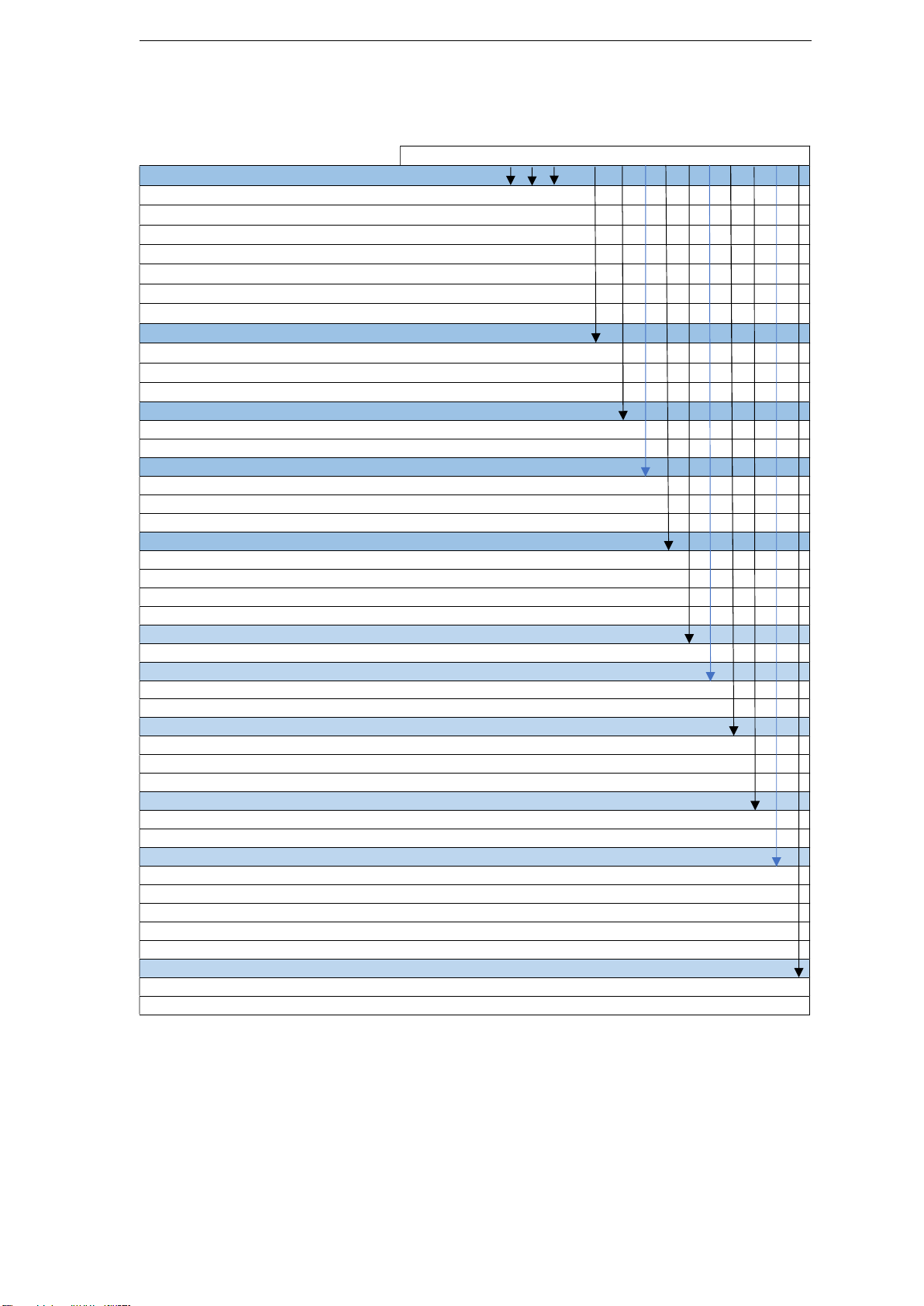
5. Order Code
RS3 x x x - x x x x 0 x x x x x
Current Rathing
60 A 0 6 0
75 A 0 7 5
210 A 2 1 0
Max Voltage
480 V
600 V
690 V
4
6
7
Order Code 9
Page 10

PMA-Relay S 3PH from 60A to 210A
6. Technical Specifications
6.1. General features
Cover and Socket material PolymericV2
Utilization Category AC-51 AC-55b
IP Code 20
Method of Connecting Load in Delta, Load in Star
Auxiliary voltage (only with HB option) 24V dc/ac (max 70mA)
Relay output for Heater Break Alarm (only with HB option) 0.5A a 125Vac
6.2. Input features
Logic input SSR 5 ÷ 30Vdc 9mA Max (ON >5Vdc OFF <4Vdc)
Logic input SSR with HB option 4 ÷ 30Vdc 5mA Max (ON >4Vdc OFF <1Vdc)
Analog Input V 0 ÷ 10Vdc (15 kΩ)
Analog Input A 0 ÷ 20mA / 4 ÷ 20mA (100 Ω)
Digital Input calib. (only with HB option) 12 ÷ 24V dc/ac (max 4mA)
6.3. Output features (power device)
Nominal
Current
(A) (V) (480V) (600V) (mAeff)
60 24÷600 1200 1600 600 1900 15 8680 47÷70 353 3000
90* 24÷600 1200 1600 600 1900 15 8680 47÷70 482 3000
120 24÷600 1200 1600 600 1900 15 14280 47÷70 598 3000
150 24÷600 1200 1600 300 5000 15 17500 47÷70 594 3000
180 24÷600 1200 1600 300 5000 15 30800 47÷70 740 3000
210 24÷600 1200 1600 300 5000 15 53900 47÷70 898 3000
Voltage
range
(Ue)
Repetitive peak
reverse voltage
(Uimp)
Latching
current
Max peak
one cycle
(10msec.)
(A)
Leakage
current
(mAeff)
*75A for UL
FUSE I2T
value
Suggested
A2s
(at500V)
tp
= 10msec.
Power loss
Frequency
range
(Hz) I=Inom (W) (V)
Thyristor
+
Fuse
6.4. Fan Specification (60 to 90A)
Supply: 230Vac Standard Power 32W (16W for 2 Fans)
Supply: 115Vac Option Power 28W (14W for 2 Fans)
Supply: 24Vdc Option Power 14W (7W for 2 Fans)
6.5. Fan Specification (120 to 210A)
Supply: 230Vac Standard Power 48W (16W for 3 Fans)
Supply: 115Vac Option Power 42W (14W for 3 Fans)
Supply: 24Vdc Option Power 21W (7W for 3 Fans)
Isolation
Voltage
(Ui)
10 User Manual
Page 11

PMA-Relay S 3PH from 60A to 210A
6.6. Environmental installation conditions
Ambient temperature
Storage temperature
Installation place
Altitude
Humidity From 5 to 95% without condense and ice
Pollution Level Up to 2nd Level ref. IEC 60947-1 6.1.3.2
0-40°C (32-104°F) at nominal current.
Over 40°C -104°F use the derating curve.
-25°C to 70°C
-13°F to 158°F
Don’t install at direct sun light, where there are conductive dust,
corrosive gas, vibration or water and also in salty environmental.
Up to 1000 meter over sea level.
For higher altitude reduce the nominal current of 2% for each 100m
over 1000m
6.7. Derating Curve
For higher cabinet
Temperature contact
the producer of the unit
Technical Specifications 11
Page 12

PMA-Relay S 3PH from 60A to 210A
7. Installation
Before to install, make sure that the Thyristor unit have
not damages.
If the product has a fault, please contact the dealer from
which you purchased the product. Verify that the product
is the same thing as ordered.
The Thyristor unit must be always mounted in vertical
position to improve air cooling on heat-sink.
Maintain the minimum distances in vertical and in
horizontal as represented.
When more unit has mounted inside the cabinet
maintain the air circulation like represented in figure.
Sometimes is necessary installing a fan to have better
air circulation.
7.1. Dimensions and weight
Width Height Depth Weight
Relay S 3PH 60-90A (SR16) 187 mm 274 mm 170 mm 7 kg
Relay S 3PH 120-210A (SR17) 281 mm 274 mm 170 mm 10.6 kg
12 User Manual
Page 13

PMA-Relay S 3PH from 60A to 210A
7.2. Fixing holes
Relay S 3PH 60-90A (Size SR16) Relay S 3PH120-210A (Size SR17)
Installation 13
Page 14

PMA-Relay S 3PH from 60A to 210A
8. Wiring instructions
The Thyristor unit could be susceptible to interferences lost by near equipments or by the power
supply, for this reason in accord to the fundamental practices rules is opportune take some
precautions:
• The coil contactor, the relays and other inductive loads must be equipped with opportune RC
filter.
• Use shielded bipolar cables for all the input and output signals.
• The signal cables must not be near and parallel to the power cables.
• Local regulations regarding electrical installation should be rigidly observed.
Use copper cables and wires rated for use at 90°C only.
Power cable torque (suggested)
Type
060
090*
120
150
180
210
*75A for UL
Connector
Type
Screw M6 70.8 (8.0)
Screw M8 141.6 (16.0)
Cable dimensions of the Command Terminals:
0.5 mm² (AWG 18)
Cable dimensions of the Earth (suggested):
16 mm² (AWG 6) up to 120A
25 mm² (AWG 4) up to 210A
Torque Lb-in
(N-m)
Wire Range
mm² (AWG)
16 (5)
25 (3)
35 (2)
50 (0)
70 (00)
90 (000)
MAX Current
Terminals
150 A
250 A
Wire Terminals
UL Listed (ZMVV)
Fork/Spade Terminal
Copper Tube Crimp.Lug
Fork/Spade Terminal
Copper Tube Crimp.Lug
8.1. Terminals Positions 3PH 60-90A Size
Top view
Down view
14 User Manual
Page 15

PMA-Relay S 3PH from 60A to 210A
8.2. Terminals Positions 3PH 120-210A Size
Top view
Down view
8.3. Power Terminals
Warning: Before connecting or disconnecting the unit check that power and control
cables are isolated from voltage sources.
Terminal Description
L1 Line Input Phase 1
T1 Load Output Phase 1
L2 Line Input Phase 2
L3 Load Output Phase 2
L3 Line Input Phase 3
T3 Load Output Phase 3
Wiring instructions 15
Page 16

PMA-Relay S 3PH from 60A to 210A
8.4. Command Terminals
Warning: Before connecting or disconnecting the unit check that power and control
cables are isolated from voltage sources.
8.4.1. Terminal block M1 for SSR Input
Terminal M1 Description
1 Not connected
2 Not connected
3 Not connected
4 Not connected
5 Not connected
6 Not connected
7 – Input SSR
8 + Input SSR
9 Not connected
10 Not connected
11 Fan supply (230V standard, 115V option, - 24Vdc option)
12 Fan supply (230V standard, 115V option, + 24Vdc option)
8.4.2. Terminal block M1 for Analog Input or SSR input with HB
Terminal M1 Description
1 Aux – Voltage Supply for electronic boards 24V ac/dc
2 Aux – Voltage Supply for electronic boards 24V ac/dc
3 – Cal Ext. 12/24Vdc
4 + Cal Ext. 12/24Vdc
5 C –Common contact relay alarm output (see HB Alarm contact for config.)
6 NC\NO –Normally Close\Open contact alarm relay output (see HB Alarm contact for config.)
7 – Control Input (SSR/0-10Vdc/4-20mA)
8 + Control Input (SSR/0-10Vdc/4-20mA)
9 Not connected
10 Not connected
11 Fan supply (230V standard, 115V option, - 24Vdc option, from 90 to 210A)
12 Fan supply (230V standard, 115V option, + 24Vdc option, from 90 to 210A)
16 User Manual
Page 17

PMA-Relay S 3PH from 60A to 210A
8.5. Connection Diagram for 3 phases (control on 3 phases) from 60 to 90A
Caution: this procedure must be performed only by qualified persons.
Note:
*1 A suitable device must ensure that the unit can be electrically isolated from the supply
(electromagnetic circuit breaker or by fuse isolator), this allows the qualified people to
work in safety.
* 2 Only for the HB option See par. “Heater break Alarm and SCR short circuit”
* 3 The heat-sink must be connected to the earth.
* 4 Only for the Analog Input option, the analog input isn’t isolated from Aux Supply
a series connection between analog inputs of the units is not possible.
With AC Aux supply it’s not possible connect the zero terminal of Analog Input to the earth.
With DC Aux supply is not possible to connect the zero of the power supply with the zero of
analog input
Wiring instructions 17
Page 18

PMA-Relay S 3PH from 60A to 210A
8.6. Connection Diagram for 3 phases (control on 2 phases) from 120 to 210A
Caution: this procedure must be performed only by qualified persons.
Note:
*1 A suitable device must ensure that the unit can be electrically isolated from the supply
(electromagnetic circuit breaker or by fuse isolator), this allows the qualified people to
work in safety.
* 2 Only for the HB option See par. “Heater break Alarm and SCR short circuit”
* 3 The heat-sink must be connected to the earth.
* 4 Only for the Analog Input option, the analog input isn’t isolated from Aux Supply
a series connection between analog inputs of the units is not possible.
With AC Aux supply it’s not possible connect the zero terminal of Analog Input to the earth.
With DC Aux supply is not possible to connect the zero of the power supply with the zero of
analog input
18 User Manual
Page 19

PMA-Relay S 3PH from 60A to 210A
8.7. Led status and alarms
LED Status
ON
S.C.
LED OFF
LED ON (Green)
LED OFF
LED ON (Red)
LED Flashing (Red)
LED OFF
H.B.
LED ON (Yellow)
Description
Load is NOT powered
Load is powered
Load OK
SCR short circuit (only with HB option)
Over Temperature on heat sink
Load OK
Load Fault (only with HB option)
9. Heater Break alarm and SCR short circuit
(HB Option only)
Caution: to work properly the load must be powered at least about 160msec.
The Heater Break circuit read the load current with an Internal current transformer (C.T.).
Minimum current is 10% of the current transformer size.
If load current is below this value the Heater Break Alarm doesn’t work properly.
9.1. Heater break Calibration procedure
An automatic function sets the Heater Break Alarm.
The auto setting function can be activated using the “CAL” button on front
unit, or supply with 12-24Vdc the digital input “Cal Ext.” (See Connection
Diagram).
The Heater Break calibration procedure is performed in this way:
• The Unit gives the maximum voltage output
• All LEDS are on, this means that calibration procedure is active
• The current value is stored in memory
• After about 15 second the unit comes back to the initial situation
If load current decreases for partial or total load failure (sensitivity 20%) the yellow LED HB
become ON and alarm relay change status.
If the unit is still in conduction with no input signal (LED green OFF) it means that there is a short
circuit on thyristors and red LED (SC) become ON.
If the load has been changed the Heater Break calibration procedure must be done again.
Heater Break alarm and SCR short circuit
(HB Option only) 19
Page 20

PMA-Relay S 3PH from 60A to 210A
9.2. HB Alarm contact
The Relay S unit with HB option (if available), is supplied
with Heater Break alarm contact normally opened (NO):
• In normal conditions (without alarm) and with auxiliary
power supply, the contact to the terminals has opened
(relay coil energized).
• In alarm condition or without auxiliary power supply the
contact to the terminals is closed (relay coil not energized).
If you wish to change the alarm contact open the cover of
the Master module (first on the left with terminal block) and
set the jumper as shown in the next page, don’t set the
other jumpers with factory settings.
Warning: Before operate, be sure that power and control cables are isolated from
voltage sources.
20 User Manual
Page 21

PMA-Relay S 3PH from 60A to 210A
10. Input setting
The input type is already configured in line with customer requirements that are defined in the
Order Code. However, if you wish to change the input type (ex. from 0÷10V to 4÷20mA) set the
jumpers as below represented and then do the “Input calibration procedure” Open the cover of
the Master module (first on the left with terminal block) and set the jumper as shown, don’t set
the other jumpers with factory settings not shown.
Important: The analog input isn’t isolated from Aux Supply. The series connection between
analog inputs of the units is not possible. With AC Aux supply it’s not possible connect the zero
terminal of analog input to the earth. With DC Aux supply is not possible to connect the zero
of the power supply with the zero of analog input.
Warning: Before operate, be sure that power and control cables are isolated from
voltage sources.
SSR Only Version board the other
jumpers are not mounted on PCB.
There are two type of PCB board, for
Input setting 21
Page 22

PMA-Relay S 3PH from 60A to 210A
10.1. Input calibration procedure
Warning! this procedure can be done just by specialized personnel
This procedure is needed only if you change the input type.
22 User Manual
Page 23

PMA-Relay S 3PH from 60A to 210A
11. Firing type
Choose a correct firing type allows to optimize the thyristor unit for the installed load.
The firing type has already configured in line with customer requirements, Zero Crossing for SSR
input and Burst firing for Analog Input.
Caution: this procedure must be performed only by qualified persons.
11.1. Zero Crossing (ZC) with SSR Input
ZC firing mode is used with Logic Output from temperature controllers and the Thyristor
operates like a contactor.
The Cycle time is performed by temperature controller. ZC minimizes interferences because the
Thyristor unit switches ON-OFF at zero voltage.
11.2. Burst Firing (BF) with Analog Input
The Burst Firing is similar to the Single Cycle, but consecutive cycles ON are selectable between
1 and 255, with input signal equal at 50%. When is specified 1 the firing type is Single Cycle.
Burst Firing is a method zero crossing that it reduces the electromagnetic interferences because
the thyristor switches at zero voltage crossing.
The example show the Burst Firing with Burst cycles = 4
Firing type 23
Page 24

PMA-Relay S 3PH from 60A to 210A
11.3. Burst Firing settings
The Burst Firing cycles is already configured in line with customer requirements that are defined
in the Order Code. However, if you wish to change the Burst Firing cycles (es. from 4 to 8) set the
jumpers as below represented:
Warning: Before operate, be sure that power and control cables are isolated from voltage
sources.
24 User Manual
Page 25

PMA-Relay S 3PH from 60A to 210A
12. Internal Fuse
The thyristor unit have internal fuse extrarapid at low I²t for the thyristor protection of against
the short-circuits.
The Fuses must have I²t 20% less than thyristor’s I²t. The warranty of thyristor is null if no proper
fuses are used.
Type
060 2 x 50 073 06.100 2 x 100 660 8680 12400
060 (only UL) L220971J 100 660 3998 6150 (690V)
075 (only UL) L220971J 100 660 3998 6150 (690V)
090 2 x 50 073 06.100 2 x 100 660 8680 12400
120 20 559 20.180 180 660 14280 20400
150 20 559 20.200 200 660 17500 25000
180 20 559 20.250 250 660 30800 44000
210 20 559 20.315 315 660 53900 77000
Fuse Code
Spare Part
Current
(ARMS)
Vac
FUSE I2T value
Suggested A2s
(at500V)*
FUSE I2T value
Suggested A2s
(at660V)
*I2T are multiplied for K value in function of Vac at 500V K is
equal to 0,7 (ex:12400 X 0,7 = 8680).
At 660Vac K is equal to 1.
Caution: High speed fuses are used only for the thyristor protection and can not be used
to protect the installation.
Caution: The warranty of thyristor is null if no proper fuses are used. See tab.
Warning: When it is supply, the Thyristor unit is subject to dangerous voltage, don’t
open the Fuse-holder module and don’t touch the electric equipments.
Internal Fuse 25
Page 26

PMA-Relay S 3PH from 60A to 210A
12.1. Fuses Replacement
Open the cover and remove the screws.
26 User Manual
Page 27

PMA-Relay S 3PH from 60A to 210A
13. Trouble shooting
Small problems sometimes can be solved locally with the help of the below tab of
trouble shooting. If you don’t succeed, contact us or your nearest distributor.
Symptom Indication on front
unit
Green LED (ON)
light OFF
Load current
doesn’t flow
Green LED (ON)
light ON
Load current
flow also
without input
signal
Current flows at
nominal value
but Yellow
LED (HB/SC) is
light on
Thyristor unit
doesn’t
work properly
Red LED (SC)
light ON
Yellow LED (HB)
light ON
or
Red LED (SC)
light ON
Possible reasons
of the symptom
• No Auxiliary Voltage
• No input signal
• Reversed polarities of input
signal
• Fuse failure
• Load connection interruption
• Load failure: The yellow led
(HB) is light on (with HB option)
• Thyristor fault: The red led (SC)
is light on (with HB option)
• Wrong wiring
• SCR short circuit
• HB circuit not tuned
• Current transformers
not properly wired
• Auxiliary voltage supply out of
limits
• Wrong input signal selection
• Wrong input signal calibration
(out of range)
Actions
• Give auxiliary voltage supply
(See Connection Diagram)
• Provide to give input signal
• Reverse the input signal polarity
• Change the fuse
• Check the wiring
• Check the load
• Change the thyristor module
• Check the wiring
• Change the thyristor module
• Make HB calibration procedure
• Check current transformers
wiring
• Verify the auxiliary voltage supply
• Control input signal setting
• Check input setting
Trouble shooting 27
Page 28

© PMA Prozeß- und Maschinen-Automation GmbH
P.O.Box. 310 229, D-34058 Kassel, Germany
Printed in Germany 9499-040-96711 (06/2019)
 Loading...