

Page 1
98
KS
KS98
S98K
98KS
8KS9
K
S
9
8
&
LimL
LimH
Xsd
Fnc
y0
a
c
b
d
TS.D
TS.H
TS.Mi
TE.D
TE.H
TE.Mi
t
Operating instructions
9499-040-44311
Valid from: 8432
PMA Prozeß- und Maschinen-Automation GmbH
KS 98 and KS98Plus
Page 2

Symbols used on the device
à EU conformity mark
a Attention, follow the operating instructions!
All rights reserved. No part of this document may be
reproduced or published in any form or by any means without prior written permission
from the copyright owner.
A publication of
û
PMA
Prozeß- und Maschinen-Automation GmbH
P.O.Box 310 229
D-34058 Kassel
Germany
Content
1. Operation ..........................3
2. Important technical data .................3
3. Versions ...........................4
4. Front view ..........................5
5. Mounting ..........................5
6. Electrical connections ..................6
7. Menus ...........................11
8. Maintenance .......................14
9. Scaling and calculation functions ...........15
10. Non-linear functions ...................17
11. Trigonometric functions .................17
12. Logic functions ......................19
13. Signal converters .....................21
14. Time functions ......................23
15. Selection and storage ..................26
16. Limit signalling and limiting ..............28
17. Visualization........................30
18. Communication ......................34
19. KS98+ I/O extension ...................36
20. Cross communication KS 98plus - KS98plus .....43
21. KS 800 and KS 816 connection .............45
22. Description of KS98 CAN bus extension........48
23. Programmer ........................51
24. Controllers .........................54
25. Inputs ............................61
26. Outputs ...........................63
27. Zusatzfunktionen .....................64
28. KS98 I/O extension modules...............66
29. Modular I/O extension modules ............68
30. Function management ..................74
Page 3
a
Change notice!
The Functionblock SOUT has changed since operating version 7. Eventually you must adjust your engineering when
updating Soft- or Hardware (see Page 27).
1 Operation
1.1
Description
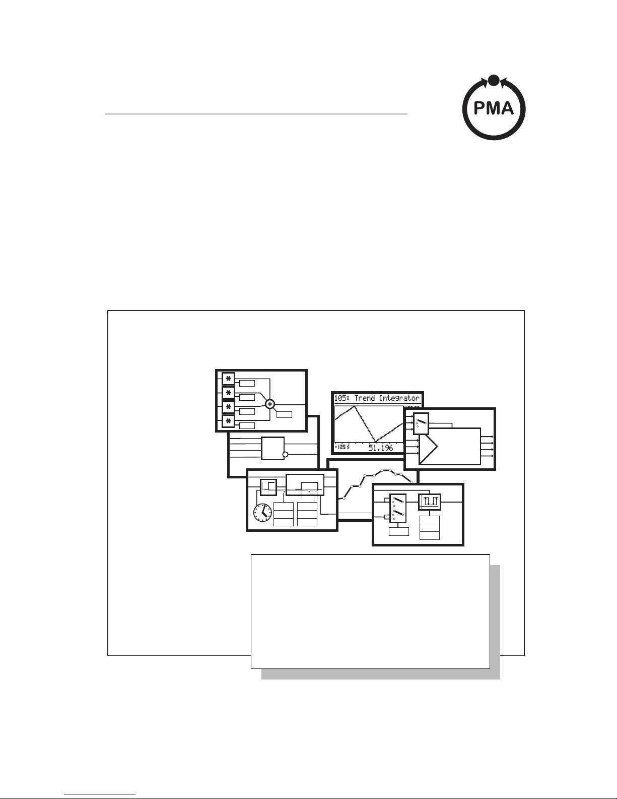
KS 98 is a freely structurable compact automation unit. Each unit contains a function library from which selection, configuration, parameter setting and combination of up to 450 function blocks is possible by means of an engineering tool. This permits realization of complex mathematical calculations, multi-channel control structures and sequencing in one instrument.
Various pages are displayed by means of an LCD (64x128 dots): input and output for analog and digital signals, bargraphs
and trends. Communication with other instruments and systems is possible via an optional digital interface.
2 Important technical data
2.1
Analog inputs r sections 6 and 25.1
INP 1: universal input, configurable for thermocouples, resistance thermometers, temperature difference, resistance
transducer, DC current and DC voltage
INP 3 (option C): DC current or -50...1300 mV, INP 4 (option C): DC current, INP 5: DC current and
DC voltage, INP 6: resistance transducer and DC current
2.2 Digital inputs
Opto-coupler for 24 V DC, current sink to IEC 1131 type1, logic 0 = -3...5 V, logic 1 = 15...30 V, approx.
5mAdi1 and di2: in all versions, di3...di7: in option B, di4...di12: in option C.
2.3 Outputs r section 26.1
Relay contact rating: 500 VA, 250 V, 2 A at 48...62 Hz
OUT1, OUT2, OUT4, OUT5: relay or logic dependent of version, OUT 3 (option C): current
2.4 Control outputs
Opto-coupler, grounded load with common positive control voltage, power 18...32 V DC ß 100 mA.
do1...do4: in option B, do5 and do6: in option C
2.5 Supply voltage
90...260V AC, 48...62 Hz, power consumption approx. 10 VA (equipped with all possible options)
For detailed technical data, see data sheet KS98 9498 737 32113
KS98+ 9498 737 37933
9499-040-44311 Operation
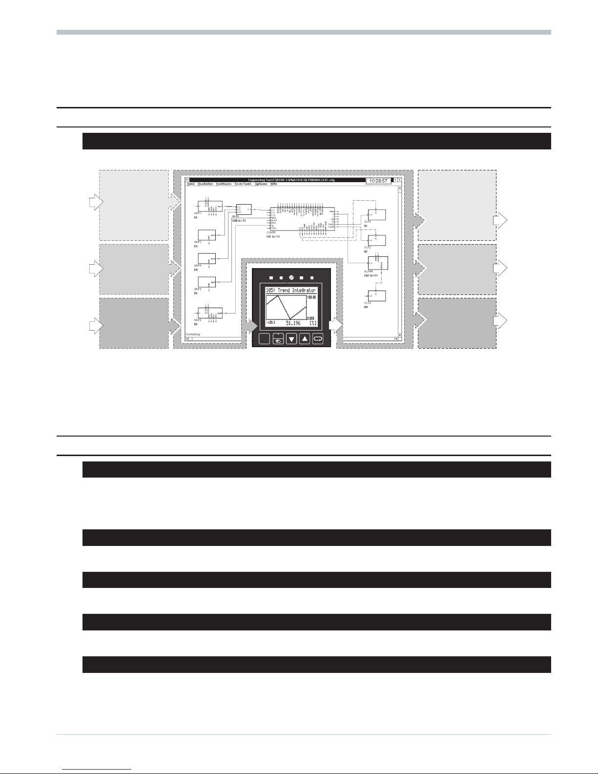
3 Description
SOFTWARE/ENGINEERING
HARDWARE
Option B
Option C
Standard
INP3
INP4
di8
di9
di10
di11
di12
di3
di4
di5
di6
di7
INP1
INP5
INP6
di1
di2
OUT3
do5
do6
do1
do2
do3
do4
Interface
OUT1
OUT2
OUT4
OUT5
HARDWARE
Standard
Option B
Option C
Page 4

3 Versions
Order no.
9407-9 - 0 1
Basic unit
Standard
6
with integrated supply voltage
7
KS98+ with CANopen I/O
8
90...250 V AC with 4 relays
3
Power supply and
90...250 V AC with 2 relays + 2 current outputs
5
process outputs
24 V UC with 4 relays
7
24 V UC with 2 relays + 2 current outputs
9
Option B
no option B
0
TTL interface + di3...7 / do1...4
1
RS 422 + di3...7 / do1...4 + real-time clock
2
PROFIBUS-DP + di3...7 / do1...4
3
INTERBUS + di3...7 / do1...4
4
Option C
no option C
0
INP3 / INP 4 / OUT 3 / di8...12 / do5 / do6
1
INP3
*2)
/ INP 4 / OUT 3 / di8...12 / do5 / do6
2
Modular option C basic card
*1)
3
Modular option C basic card with modules
*1)
4
Engineering
single-channel controller (basic unit)
0
Setting
standard setting
0
setting to specification
9
*1)
Combination KS98+ (CANopen I/O) and modular option C is not possible. Either KS98+ or modular option C!
*2)
INP3: With Type = 0...20 mA, the input is designed for -50...1300 mV. For further use of the output of INP3 with this scaling,
an x0 of -50 and an x100 of 1300 must be adjusted.
3.1 I/O modules
- for installation in units with modular option C basic card
Order no.
9407-998-00 1
Position
Separate order
0
Fitted in KS98 socket 1
1
Fitted in KS98 socket 2
2
Fitted in KS98 socket 3
3
Fitted in KS98 socket 4
4
Module type-
Analog inputs
Pt100 / 1000, Ni 100 /1000, resistance, potentio
-
meter
20
Thermocouple, mV, 0/4...20mA
21
-50...1500mV, 0...10V
22
Module type-
Analog outputs
0/2...10V, 0..._10V
30
0/4...20mA, 0..._20mA
31
Module type-
Digital inputs/outputs
Digital I/O (universal)
40
Frequency/counter input
41
Versions 9499-040-44311
I/O modules 4
Page 5
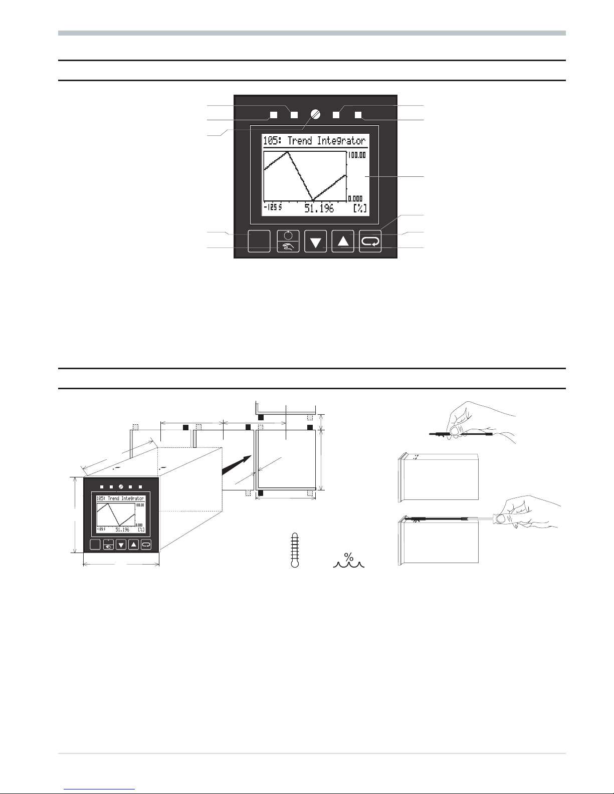
4 Front view
LED 2 e.g. cooling LED 3 e.g. alarm 1
LED 1 e.g. heating LED 4 e.g. alarm 2
Locking screw
Display e.g. trend
Selector key
PC interface Increment key (z)
Manual/automatic key Decrement key (u)
q
Locking screw: locks the controller module in the housing.
q
LEDs: indicate the statuses of the LED function (r section 27.1).
q
Display: LCD dot matrix with (64x128 dots, back lighting). The relevant display is shown in sections
7 Menus, 17 Visualization, 23 Programmer and 24 Controller.
q
Keys HDIM: The relevant function is described in section 7 Menus.
q
PC interface: PC connection for structuring/wiring/configuring/parameter setting/operating with the engineering tool.
5 Mounting
a
Mount the unit with min. 2 fixing clamps
(diagonally at top and bottom).
a
Protection type IP65:
Use 4 fixing clamps. Insert the controller module firmly and block it using the locking screw.
9499-040-44311 Front view
5 I/O modules
2
1
96 96
92
+0,8
92
?24
+0,8
1...16
min. 0°C
60°C
max.
max.
95% rel.
96
96
160
l
Page 6

Wire-hook switch S: Its switching status is signalled by function STATUS
and can be used in the engineering. After delivery, the switch is open.
For closing, release the locking screw, withdraw the controller module from the
housing, close the Wire-hook switch. Insert the unit and lock it with the
screw.
Wire-hook switch DP: The bus termination resistor can be activated by 2
S.I.L.
switches (DP) in KS98. Both S.I.L. switches must always be open or closed
(terminating resistor active).
Wire-hook switch CAN: for bus terminating resistor r see page36
a
Ensure tightness!
l
Caution! The instrument contains electrostatically sensitive components.
6 Electrical connections
6.1
Safety hints
a
Following the enclosed safety hints 9499 047 07101 is indispensable! The instrument insulation meets
standard EN 61 010-1 (VDE 0411-1) with contamination degree 2, overvoltage category III, operating
voltage range 300 V and protection class I.
a
With horizontal installation, the following rule is applicable additionally: with the instrument module
withdrawn, a facility which prevents conducting parts from dropping into the open housing must be
provided.
a
If the unit is switched to off-line, the outputs keep their status from the time of switch-over!!!
6.2 Electromagnetic compatibility
European guide line 89/336/EEC. The following European generic standards are met:
Electromagnetic radiation: EN 50081-2 and Electromagnetic immunity: EN 50082-2. The unit is suitable for use in
industrial areas (in residential areas, RF interference may occur). The electromagnetic radiation can be reduced
decisively by installing the unit in a grounded metal switch cabinet.
6.3 Measurement earth (for grounding interferences)
a
If outside interference voltages act on the instrument, functional troubles may be caused
(concerns also high-frequency interferences). For grounding the interference voltages and ensuring the
electromagnetic immunity, a measurement earth must be connected. Terminal A 11 must be connected to
ground potential by means of a short cable (approx. 20 cm, e.g. to switch cabinet ground)! This cable must
be kept separate from mains cables.
6.4 Störschutzbeschaltung
Load current free connections between the ground potentials must be realized so that they are suitable
both for the low-frequency range (safety of persons, etc.) and the high-frequency range (good EMC valu
-
es).
The connections must be made with low impedance. All metal grounds of the components installed in the cabinet Ü
or in the cabinet door * must be screwed directly to the sheet-metal grounding plate to ensure good and durable
contact. In particular, this applies to earthing rails ä, protective earth rail #, mounting
Electrical connections 9499-040-44311
Safety hints 6
CAN
S
DP
Page 7
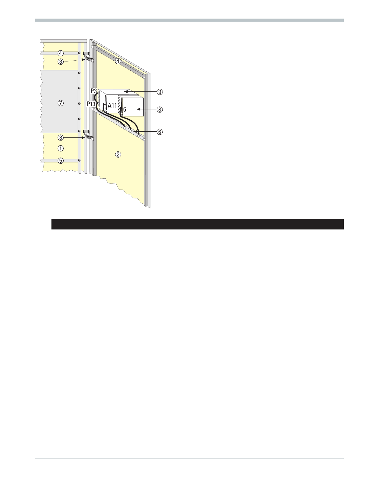
plates for switching units > and door earthing strips <.Control
-
lers KS40/50/90 y and KS92/94 x are shown as an example for
earthing. The max. length of connections is 20 cm (see relevant ope
-
rating instructions).
Generally, the yellow/green protective earth is too long to
provide a high-quality ground connection for high-frequency
interferences.
Braided copper cables Ö provide a high frequency conducting,
low-resistance ground connection, especially for connecting cabinet
Ü and cabinet door *.
Because of the skin effect, the surface rather than the cross
section is decisive for low impedance. All connections must
have large surfaces and good contact. Any lacquer on the
connecting surfaces must be removed.
Due to better HF properties, zinc-plated mounting plates and
compartment walls are more suitable for large-surface grounding
than chromated mounting plates.
6.5 Connecting diagram
w
Power supply cables must be kept separate from signal and measuring cables.
w Twisted and screened measuring cables have to be used (screening connected with measurement earth).
w
Connected final elements must be equipped with protective circuits to manufacturer specifications.
This avoids voltage peaks which can cause trouble to the instrument.
w
The instruments must be protected additionally by an individual or common fuse for a max. power consumption of 10
VA per unit (standard fuse ratings, min. 1 A)!
a
Signal and measurement circuits may carry max. 50 Vr.m.s. against ground,
mains circuits may carry max. 250 V r.m.s between terminals.
9499-040-44311 Electrical connections
7 Connecting diagram
Page 8

galvanic isolations
Bei Geräten mit Modularer Option C
r siehe Anschlußbild Seite 67
* Versions with integrated supply voltage only
** With 24 V DC or AC, protective earth must also be connected. With 24 DC, the polarity is uncritical.
Electrical connections 9499-040-44311
Connecting diagram 8
1
2
3
4
5
6
7
8
9
10
11
12
13
14
15
16
24 V
di8( )
di9( )
di 10 ( )
di 11 ( )
di 12 ( )
do 5
do 6
GND
+
_
+
_
+
_
-
+
+
+
+
+
+
.
C
INP4
INP3
OUT3
0/4...20mA
0/4...20mA
0/4...20mA
1
2
3
4
5
6
7
8
9
10
11
12
13
14
15
P
OUT4
OUT5
OUT2
OUT1
0/4...20mA
+
_
ßßß500VA, 250V, 2A
ßßß500VA, 250V, 2A
1
2
3
4
5
6
7
8
9
10
11
12
13
14
15
16
di (-) CAN-GND
di 1 (+) CAN-H
di 2 (+) CAN-L
+ Volt
+mA
_
Volt/mA
Volt
mA
A
INP5
INP6
INP1
0/4...20mA
100%
0%
0%
100%
}}2
1
+
_
+
_
+
_
1
2
3
4
5
6
7
8
9
10
11
12
13
14
15
16
B
-
+
+
+
+
+
+
24 V
di3( )
di4( )
di5( )
di6( )
di7( )
do 1
do 2
do 3
do 4
RXD-B
GND
RXD-A
TXD-B
TXD-A
RS422 RS485 TTL PROFIBUS
+5V
GND
TRE
TXD
RXD
VP
GND
RxD/TxD-N
RxD/TxD-P
RGND
DATA B
DATA A
100 [
abcd efg
ABCP
1
16
1
16
(Option)
(Option)
-
OUT
IN
INTERBUS
AB
0/4...20mA
+
_
*
_
+
*
_
+
**
Ra
Page 9
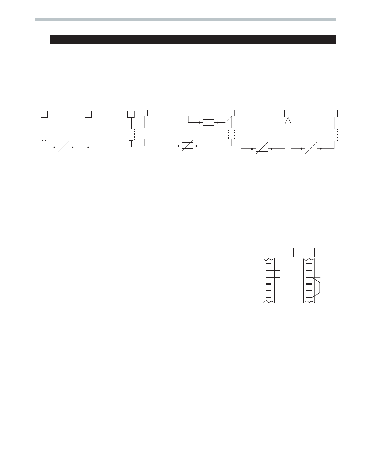
6.6 Analog inputs (r connecting diagram)
Thermocouples (a)
No lead resistance adjustment.
Internal temperature compensation: compensating lead up to the instrument terminals. With AINP1,
STK = int.CJC must be configured.
External temperature compensation: Use separate cold junction reference with fixed reference temperature.
Compensating lead is used up to the cold junction reference. Copper lead between reference and instrument. With
AINP1, STK = ext.CJC and TKref = reference temperature must be configured.
Resistance thermometer Pt 100 in 3-wire connection (b)
No lead resistance adjustment is necessary, if RL1 = RL2.
Resistance thermometer Pt 100 in 2-wire connection (c)
Lead resistance adjustment is necessary: Ra must be equal to RL1 + RL2.
Two resistance thermometers Pt100 for difference measurement (d)
Lead resistance compensation: proceed as described on page13 - 7.7.
Resistance transducer (e)
Measurement calibration: proceed as describedon page13 - 7.7..
Standard voltage signals 0/2...10V (g)
Input resistance: ? 100 k[, configure scaling and digits behind the decimal point.
INP5 is a difference input, the reference potential of which is connected to
terminal A9. With voltage input, A6 must always be connected to A9.
Standard current signals 0/4...20 mA (f)
Input resistance: 50 [, configre scaling and digits behind the decimal point.
DC voltage -50...1300 mV
(only for INP3 in instruments with order no. 9407-9xx-x2xx1):
With Type = 0...20 mA, the input is designed for -50...1300 mV. For further use of the output of INP3 with this scaling,
an x0 of -50 and an x100 of 1300 must be adjusted.
a
The inputs INP1 / INP6 are interconnected. This must be taken into account if both inputs must be used for standard
current signal. If necessary, galvanic isolation should be used.
9499-040-44311 Electrical connections
9 Analog inputs (r connecting diagram)
RL2
14
16
15
RL1 = RL2
RL1
}
b
RL2
14
16
15
Ra = RL1+RL2
Ra
c
RL1
}
RL2
14
16 15
RL1
xeff = 1 - 2}}
}1 }2
d
4
5
6
7
8
9
mAmA+
-
4
5
6
7
8
9
Volt
Volt
+
-
INP5 INP5
Page 10
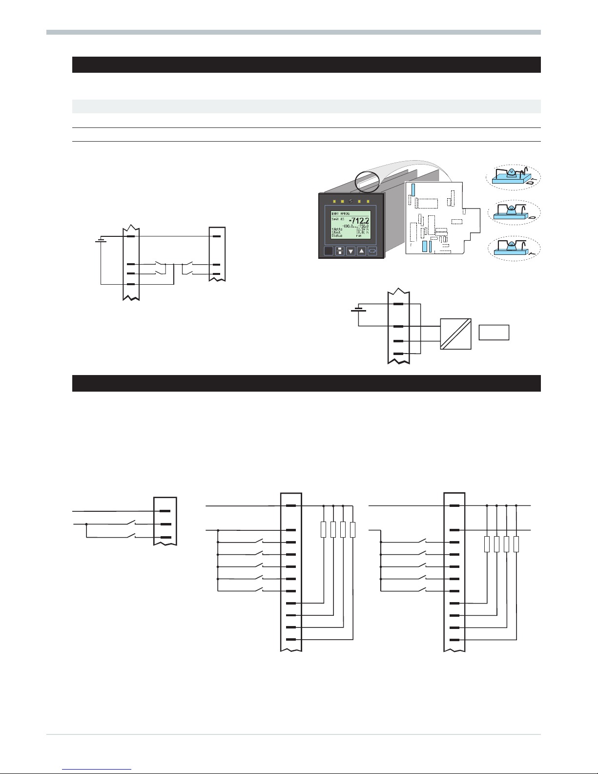
6.7 Versions with integrated supply voltage
The potential-free supply voltage can energize a 2-wire transmitter or max. 4 control inputs. Its output connectors are
selectable by means of 3 S.I.L. switches:
Connectors Ü* Ö Remarks
14 (+) 12 (-) T open closed
Only available with INP1 configured for current or thermocouple
4 (+) 1 (-) D closed open
The voltage input of INP5 is not available
Factory setting: Ü =T,* = open, Ö = closed (T). For chan
-
ging the switch positions, the instrument must be with
drawn from its housing. The S.I.L switches are
accessible on the circuit board indicated below
Connecting a 2-wire transmitter (e.g. INP1)
* If A14/A12 is used for di1/di2, A12 muß be linked
with A1.
6.8 Digital inputs and outputs (r connecting diagram)
The digital inputs and outputs must be energized from one or several external 24 V DC sources. Power consumption is
5 mA per input. The max. load is 0,1 A per output. Examples:
Digital inputs (connector A) Digital inputs and outputs at one Digital inputs and outputs at two
voltage source (e.g. connector B) voltage sources (e.g. connector B)
Electrical connections 9499-040-44311
Versions with integrated supply voltage 10
13
15
+
_
+
_
+
_
1 (12)
4 (14)
A
INP1
Connection 2-wire-transducer (e.g. INP1)
Ö
*
Ü
*
Ö
Ü
di 1
di 2
2
3
+
_
1 (12)
4 (14)
A
*
B
1
3
4
di 3
di 4
(Option)
Energizing digital inputs (e.g. di1...di4)
()()-
+
()()-
+
24V
(ext.1)
24V
(ext.2)
Imax. 70 m A
Imax. 6 mA
Imax. 6 mA
Imax. 6 mA
Imax. 6 mA
Imax. 6 mA
Imax. 70 m ARLImax. 70 m A
Imax. 70 m A
B
1
2
3
4
5
6
7
8
9
10
11
do 1
do 2
do 3
do 4
di 3
di 4
di 5
di 6
di 7
()()-
+
24V (ext.1)
Imax. 0,1 A
Imax. 5 mA
Imax. 5 mA
Imax. 5 mA
Imax. 5 mA
Imax. 5 mA
Imax. 0,1 ARLImax. 0,1 A
Imax. 0,1 A
B
1
2
3
4
5
6
7
8
9
10
11
do 1
do 2
do 3
do 4
di 3
di 4
di 5
di 6
di 7
()()-
+
24V (ext.)
Imax. 5 mA
Imax. 5 mA
A
1
2
3
di 1
di 2
Page 11
7 Menus
Instrument operation is menu-guided. Distinction of complete dialog and short-form dialog is made. In the complete dialog,
the main menu with its sub-menus is displayed, i.e. all permitted settings are selectable. During short-form dialog, the main
menu is switched off, i.e. unauthorized or accidental access is prevented and only the operating page menu with the permit
-
ted operating pages is selectable. The short form dialog is available from operating version 2.
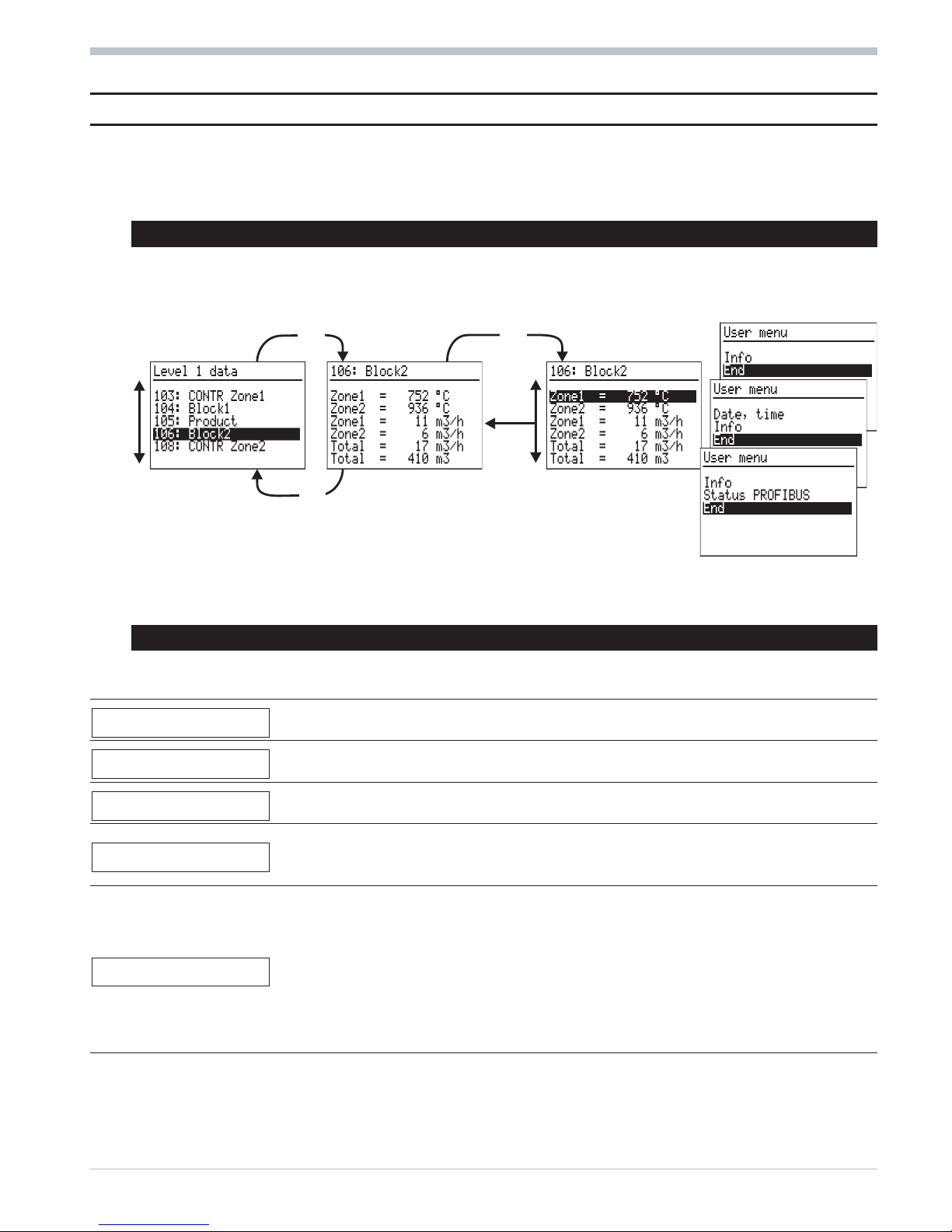
7.1 Short-form dialog
Available from operating version 2. The main menu is switched off via interface (m-hide) or function STATUS
(m-hide). The operating page menu with the permitted operating pages is selectable. Selecting, marking lines
and value adjusting are done as described below.
When pressing key M during>3s,auser menu which is different dependent of
instrument version (standard / real-time clock / PROFIBUS) is displayed:
Line Info: hardware order no., software order no., software version and operating version.
Line Date, time: display and adjustment of date and time.
Line Status PROFIBUS: status of bus access, parameter setting, configuration and data communication.
7.2 Complete dialog
A main menu for selecting the five sub-menus, using which an application-dependent number of pages can be selected.
Sub-menu Contents of pages
Level 1 data
The operating pages VWERT, VPARA, VBAR, VTREND, APROG, DPROG, CONTR, CONTR+
and PIDMA are displayed: display and adjust the operating values.
Parameter
A page is provided for each function used with which parameters are adjustable:
display and adjust parameters.
I/O data
A page is provided for each function used:
display of input and output data
Configuration
A page is provided for each function used, which must be configured:
display and adjust configurations. For changing the configuration, the instrument must be
set to ‘Offline’ (r Operating modes).
Miscellaneous
Page Date, time: display and adjust date and time. Ü
Page Device data: display and adjust interface, mains frequency and language.
Page Online/Offline: on-line i off-line, cancel configuration.
Page Calibration: display and calibrate all signals to be calibrated.
Page Info: display hardware / software order no., software version no. *
Page Status CAN-BUS: status of any connected CAN nodes. Ö
Page Status PROFIBUS/INTERBUS: display status of bus access and data
communication. ä
Ü
Only with option B with real time clock
*
From operating version 2, the operating version is also displayed.
Ö
Only with option KS98+ with CAN I/O extension (r 19 KS98+ I/O extension with CANopen interface)
ä
Only with option B with PROFIBUS/I
NTERBUS
9499-040-44311 Menus
11 Short-form dialog
D
I
D
I
M
M
D
Page 12
Prior to operating version 2, KS 98: was displayed additionally in the headers of the main menu and the five
sub-menus. Example: KS 98: Main menu
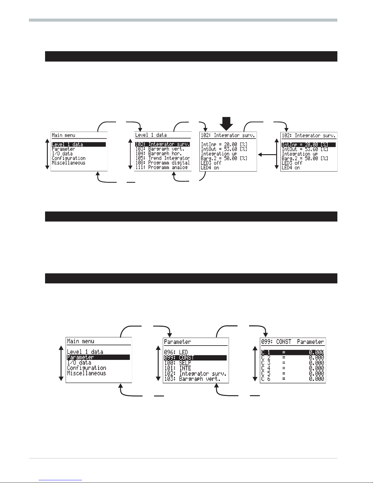
7.3 Selection (switching on and operating pages)
After power switch-on, the instrument starts up with a logo and Main menu wait! and then the main
menu is displayed during several seconds. Unless a selection is made during this time, the first operating page
entered in the sub-menu without marked line is displayed. Pressing keys I / D marks one line at a time (inverse
display). When reaching the page without marked line again by means of keys I / D, return to the sub-menu is by
pressing key M. When reaching the End in the sub-menu by pressing keys I / D, return to the main menu is
possible by pressing the M key.
Keys I / D scroll the marked line up to the start or down to the menu end. When pressing the key again, the
marked line changes from the start to the end, or vice versa.
7.4 Language selection
English: Mark Allgemeine Daten r Gerätedaten r Sprach = deutsch.
Press M: deutsch blinks. Press I: english blinks. Press M: Main menu is indicated.
German: Mark Miscellaneous r Device data r Langu. = english.
Press M: english blinks. Press D: deutsch blinks. Press M: Hauptmenü is indicated.
French: Mark Divers r Donn er d´appar. r Langu. = francais.
Press M: francais blinks. Press D 2x:francais blinks. Press M: Menu principal is indicated.
7.5 Selection (other pages)
Select sub-menu (inverse display) in the main menu with IDand open it with M. Select page with IDand
open it with M. The first line is marked (inverse, r Adjusting values). When reaching End with ID, return to
the sub-menu is with M. When reaching End in the sub-menu with ID, return to the main menu is with M.
Example: parameters
Keys I / D scroll the marked line up to the start or down to the menu end. When pressing the key again, the mar
-
ked line changes from the start to the end, or vice versa.
Menus 9499-040-44311
Selection (switching on and operating pages) 12
End
.
.
.
D
I
D
I
M M
M
D
I
M
D
D
I
D
I
End
.
.
.
D
I
End
.
.
.
M
M
M
M
Page 13

7.6 Adjusting values
Values in marked lines of pages can be adjustable. For this, the required line or value is marked with ID (inverse
display). When confirming the value with M, it starts blinking and can be adjusted with ID. When reaching the
required value, confirm it with M. Now, ID can be pressed to mark another line.
Example: bargraph vertical Example: parameter CONTR+
7.7 Calibration
Select (ID) item Calibration in sub-menu KS98: Miscellaneous and open it (M). Mark the
bottommost line (inverse display, e.g. Quit) by pressing I. Continue as follows:
Transducer input (INP1 or INP6) 2 resistance thermometers in difference (INP1)
Calibration of transducer start and end: Calibration of lead resistance effect:
Ü
Set transducer to start (r section Operating modes)
Ü
Short-circuit both thermometers in the connecting head
*
Press M
r
Quit blinks *
*
Press M
r
Quit blinks *
Ö
Press I
r
Set 0% blinks
Ö
Press I
r
Set Dif blinks
ä
Wait until the input has settled (min. 6 s)
ä
Wait until the input has settled (min. 6 s)
#
Press M
r
0% done is displayed
#
Press M
r
Cal done is displayed
<
Set transducer to end (r section Operating modes) Lead resistance adjustment is finished. Remove both
short circuits. For exit from calibration press D until
nothing is marked and then press M.
* if another word blinks, press key I or D as many
times as necessary, until the required dialogue
blinks.
>
Press M
r
0% done blinks
y
Press I 3xrSet 100% blinks
x
Wait until the input has settled (min. 6 s)
c
Press M
r
100% done is displayed
Calibration is finished. For exit from calibration
press D until nothing is marked and then press M.
7.8 Operating modes
q
Online/Offline
For configuration changing, switch the unit to ‘Offline’ and back to ‘Online’ ( Miscellaneous,
Online/Offline).
q
Manual/automatic operation
When using controllers, automatic or manual operation may be requested by several points. The controller leaves the
manual mode, when all control signals request automatic operation.
Example: INP6 is provided for potentiometric transducer and connected accordingly (position feed-back). When it is
calibrated, the controller can be switched to manual mode on the calibrating page (by means of H, Man. is
displayed on the bottom left). Line Y can be marked by pressing I and M and the actuator can be driven to its
limits with I / D. After calibration, the manual mode must be switched off on this page (press H again).
9499-040-44311 Menus
13 Adjusting values
D
I
M
M
D
I
M
M
Page 14

8 Maintenance
8.1
Behaviour in case of trouble
The unit needs no maintenance. In case of trouble, check:
w
the unit for on-line operation,
w
the power supply for correct voltage, correct frequency and correct connection,
w
all connections for correctness,
w
sensors and final elements for correct function,
w
the engineering for correctness,
w
the configuration for required operation and
w
the adjusted parameters for required effects.
If the unit does not function correctly after these checks, it must be shut down and replaced. A defective unit can be
returned to the supplier for repair.
8.2 Shut-down
Disconnect the supply voltage completely and protect the unit against accidental operation. Before switching off,
check that other equipment in the same signal loop is not affected. If necessary, appropriate measures must be
taken.
8.3 Cleaning
Housing and front panel can be cleaned using a dry, lint-free cloth. No use of solvents or cleansing agents!
8.4 Further information
Order no.
For a structured single-channel controller
operating instructions 9499-040-51001
For the Engineering-Tool
operating instructions 9499-040-45701
For the digital interface (ISO1745)
interface description 9499-040-45111
For the PROFIBUS
interface description 9499-040-52711
For the I
NTERBUS
interface description 9499-040-57011
Engineering manual
manual 9499-040-44911
This manual includes the operating instructions 9499-040-45701 for the engineering tool and the manual
9499-040-50611 for KS 98 Multi Function Unit.
Maintenance 9499-040-44311
Behaviour in case of trouble 14
Page 15
Software functions
The function blocks are described basically. Analog inputs are described with x, digital inputs with d, analog outputs
with y and digital outputs with z. Range “Real” is within -29 999 and 200 000. The max. permissible length of the
value is 6 digits (inclusive of minus sign and decimal point), with max. 3 digits behind the decimal point. With time
adjustment, negative values are not permissible.
To prevent engineering errors which would result in operating error, we recommend making own engineerings by
means of the KS98 engineering tool only. It offers a graphic user interface, manages function blocks and scanning
times and permits parameter setting and configuration by means of the relevant short-form descriptions. Text entry is
also possible (block title, units and other user-specific texts).
9 Scaling and calculation functions
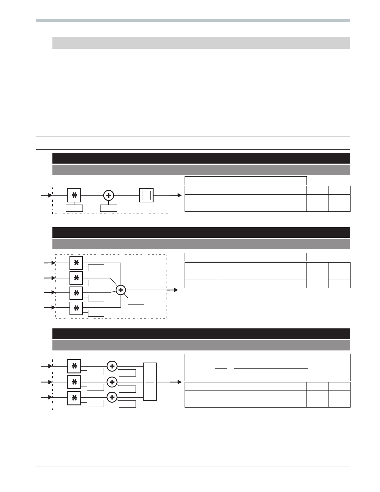
9.1
ABSV
(absolute value - no. 01)
||
yaxa
110
=× +
Parameter Description Values Default
a
Multiplication factor
Real
1
a0
Offset 0
9.2 ADSU
(addition / subtraction - no. 03)
yaxbxcxdxy
1123 40
=× +× +× +× +
Parameter Description Values Default
a...d
Multiplication factor
Real
1
y0
Offset 0
9.3 MUDI
(multiplication / division - no. 05)
y
AB
C
ax a bx b
cx c
1
10 20
30
=
×
=
×+ ××+
×+
()()
Parameter Description Values Default
a...c
Multiplication factor
Real
1
a0...c0
Offset 0
9499-040-44311 Scaling and calculation functions
15 ABSV
x1
A
y1
a0a
A
x1
x2
x3
x4
y1
y0
a
c
b
d
x1
x2
x3
y1
A
B
C
a0
b0
c0
a
c
b
A*B
C
Page 16
9.4 SQRT
(square root function - no. 08)
yaxa y
1100
=×+ +
Parameter Description Values Default
a
Multiplication factor Real 1
a0
Input offset 0
y0
Output offset 0
9.5 SCAL
(scaling - no. 09)
yaxa
Exp
110
=× +()
Parameter Description Values Default
a
Multiplication factor
Real
1
a0
Offset 0
Exp
Exponent -7...+7 1
9.6 10EXP
(10s exponent - no. 10)
y
x11
10=
9.7 EEXP
(e function - no. 11)
ye
x11
=
9.8 LN
(natural logarithm - no. 12)
yx
1
ln 1)= (
9.9 LG10
(10s logarithm - no. 13)
yx
1
log 1)= (
Scaling and calculation functions 9499-040-44311
SQRT 16
x1 y1
a0
y0
a
x1 y1
a0a Exp
EXP
x1 y1
10
x1
x1 y1
e
x1
x1 y1
ln
x1 y1
log
10
Page 17
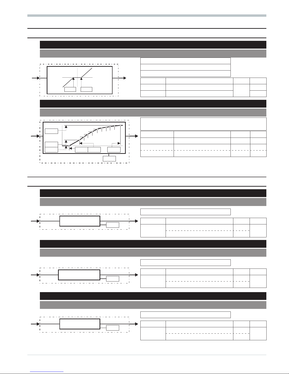
10 Non-linear functions
10.1
GAP
(dead band - no. 20)
yxL
1
1= \
with x1 < L
y
1
0=
with x1 = L...H
yxH
1
1= \
with x1 > H
Parameter Description Values Default
Low
Lower limit value
Real
0
High
Upper limit value 0
10.2 CHAR
(function generator - no. 21)
With max. 11 value pairs (input / output) non-linear functions
are simulated or linearized.
Configuration Description Values Default
Seg
Number of segments 1...10 1
x(1...11)
Input value for curve point Real *
y(1...11)
Output value for curve point 0
* 0 for x1, x3...x11 and 1 for x2
11 Trigonometric functions
11.1
SIN
(sinus function - no. 80)
yx
1
sin 1)= (
Parameter Description Values Default
Select
Unit: degree of angle 0 0
Unit: arc measure 1
11.2 COS
(cosinus function - no. 81)
yx
1
cos 1)= (
Parameter Description Values Default
Select
Unit: degree of angle 0 0
Unit: arc measure 1
11.3 TAN
(tangent function - no. 82)
yx
1
tan 1)= (
Parameter Description Values Default
Select
Unit: degree of angle 0 0
Unit: arc measure 1
9499-040-44311 Non-linear functions
17 GAP
x1 y1
y
x
y=x-High
y=x-Low
Low
High
x1 y1
y
x
( 10)ß
1
2
3
4
5
6
7
8
9
10
y1
y2
y11
x1 x2 x11
...
...
Seg
x1 y1
Select
(y1) = sin (x1)
x1 y1
Select
(y1) = cos (x1)
x1 y1
Select
(y1) = tan (x1)
Page 18
11.4 COT
(cotangent function - no. 83)
yx
1
cot 1)= (
Parameter Description Values Default
Select
Unit: degree of angle 0 0
Unit: arc measure 1
11.5 ARCSIN
(arcus sinus function - no. 84)
yx
1
arcsin 1)= (
Parameter Description Values Default
Select
Unit: degree of angle 0 0
Unit: arc measure 1
11.6 ARCCOS
(arcus cosinus function no. 85)
yx
1
arccos 1)= (
Parameter Description Values Default
Select
Unit: degree of angle 0 0
Unit: arc measure 1
11.7 ARCTAN
(arcus tangent function - no. 86)
yx
1
arctan 1)= (
Parameter Description Values Default
Select
Unit: degree of angle 0
0
Unit: arc measure 1
11.8 ARCCOT
(arcus cotangent function - no. 87)
yx
1
arccot 1)= (
Parameter Description Values Default
Select
Unit: degree of angle 0
0
Unit: arc measure 1
Trigonometric functions 9499-040-44311
COT 18
x1 y1
Select
(y1) = cot (x1)
x1 y1
Select
(y1) = arcsin (x1)
x1 y1
Select
(y1) = arccos (x1)
x1 y1
Select
(y1) = arctan (x1)
x1 y1
Select
(y1) = arccot (x1)
Page 19
12 Logic functions
12.1
AND
(AND gate - no. 60)
z d AND d AND d AND d
11234
=
zz
21
=
12.2 NOT
(inverter - no. 61)
zd
11
=
12.3 OR
(OR gate - no. 62)
z d OR d OR d OR d
11234
=
zz
21
=
12.4 BOUNCE
(debouncer - no. 63)
for de-bouncing a logic signal
Parameter Description Values Default
Delay
Switch-on and off delay time [s] Real 0
12.5 EXOR
(exclusive OR gate - no. 64)
zdEXORd
11 2
=
zz
21
=
12.6 FLIP
(D flipflop - no. 65)
The status of d1 is transferred to z1, when
- d2 changes from 0 to 1 (positive flank) and
- d3 is logic 0.
If d3 is logic 1, z1 is logic 0.
zz
21
=
9499-040-44311 Logic functions
19 AND
d1
d2
d3
d4
z1
z2
&
d1 z1
1
d1
d2
d3
d4
z1
z2
?1
d1
z1
Delay
Delay Delay
d1
d2
z1
z2
=1
signal
clock
reset
d1
d2
d3
z1
z2
Page 20
12.7 MONO
(monoflop - no. 66)
Positive pulse of length T1 at z1, if a positive flank is detected
at d1 (0 r 1) and
Positive pulse of length T2, when a negative flank is detected at
d2 (1 r 0).
zzandzz
21 43
==
Parameter Description Values Default
Ti1
Pulse duration in s (d1,Mode1=0) Real 1
Ti2
Pulse duration in s (d2,Mode2=0) Real 1
Mode1
Source of pulse duration T1= Ti1 0
0
Source of pulse duration T1 = x1 1
Mode2
Source of pulse duration T2= Ti2 0
0
Source of pulse duration T2 = x2 1
12.8 STEP
(step function for sequencing - no. 68)
For conditional switch-on or as a ring counter. The STEP function can be cascaded.
d1...d10 Condition inputs for switching on
x1 Input for cascading
d11=1 reset (y1 is set to 1 or to x1)
d12=1 stop (y1 and z1 remain unchanged)
d13 skip (switch-on with positive flank)
y1 Active step number (or + x1)
z1 1 = STEP function is active or in reset
12.9 TIME1
(timer - no. 69)
The status change of d1 is output with delay at z1. The delay is
T1 or x1 for the positive flank, T2 or x2 for the negative flank.
zz
21
=
Parameter Description Values Default
T1
Delay time in s (d1=0r1)
Real
0
T2
Delay time in s (d1=1r0) 0
Configuration Description Values Default
Mode
Delay times = T1/T2 0
0
Delay times = x1/x2 1
Logic functions 9499-040-44311
MONO 20
x1
d1
x2
d2
z1
z2
z3
z4
Ti1
Mode1
Ti2
Mode2
T1
T1
T1
T2T2T2
d11
d12
d13
reset
stop
skip
Casc
activ
Step
d1
d10
...
x1
z1
y1
STEP
x1
x2
d1
z1
z2
Mode
T1
T1
T2
t
t
T2
T1
T2
Page 21
13 Signal converters
13.1
AOCTET
data type conversion
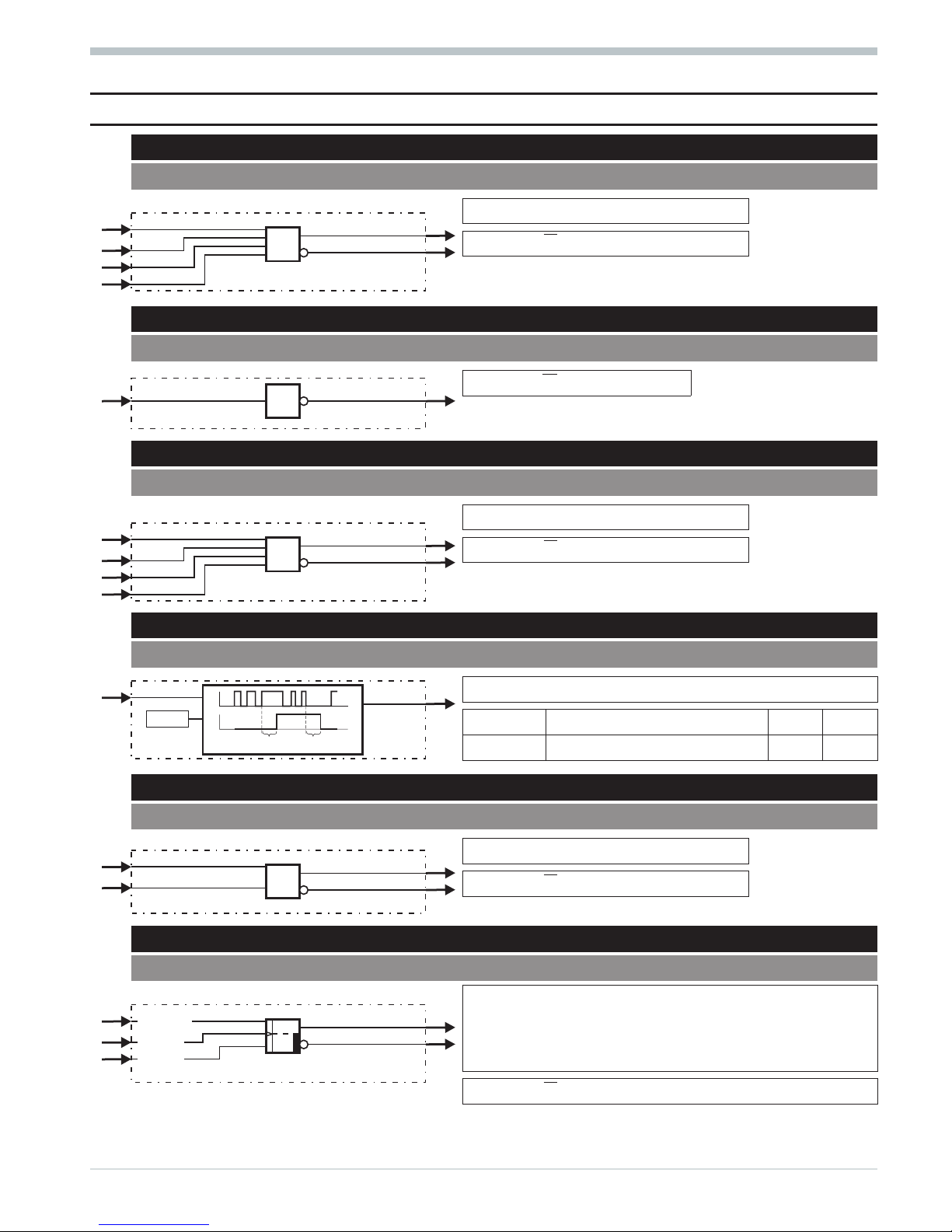
Function AOCTET converts an analog value (X1) into the individual bytes (Ooct1-4) of a data
type as used e.g. for transmission via the CAN bus ( see CPREAD / CPWRIT ). In the CAN
notation, the bytes are transmitted in Intel format. Unless connected instruments are in
compliance with this notation, word or bytewise echange of the bytes may be necessary.
The function works in both directions simultaneously ( analog > bytes / bytes > analog )
with separate data type adjustment in the parameters.
Analog inputs:
X1 analog input value
Ioct1..4 analog input byte value 1
Analog outputs:
Y1 analog output value
Ooct1..4 analog output byte value 1
Parameters:
Ioct data type of analog > byte conversion
Ooct data type of byte > analog conversion
The following data types
are available
0: Uint8
1: Int8
2: Uint16
3: Int16
4: Uint32
5: Int32
6: Float
13.2 ABIN
(analog i binary convertion - no. 71)
Converts analog value x1 into digital value z1...z8 and converts digital
value d1...d8 into analog value y1. Either binary: z1/d1 = LSB or BCD:
z1...z4/d1...d4 = LSD, z1/z5/d1/d5 = LSB or 1 of 8: z1/d1 = 1
Configuration Description Values Default
Select
analog r binary and vice versa 0
0analog r BCD and vice versa 1
analog r 1 of 8 and vice versa 2
13.3 TRUNC
(integer portion - no. 72)
Provides the integer portion of x1 (not rounded!) to y1.
yINTx
11
= ()
13.4 PULS
(analog-pulse convertion - no. 73)
Value x1 is converted into a number of pulses/h.
n Puls h
xx
xx
=×
10
100 0
\
\
n
max.
= 18 000/h with ts=100 ms Parameter Description Values Default
n
max.
= 9 000/h with ts=200 ms
x0
Start
Real
0
n
max.
= 4 500/h with ts=400 ms
x100
End 1
nmax. = 2 250/h with ts=800 ms
Puls/h
Pulses/h 0...nmax. 0
9499-040-44311 Signal converters
21 AOCTET
x1
d1
d8
...
z1
z8
y1
...
1 aus 8
BCD
Binär
2
2
2
0
1
7
1 aus 8
BCD
Binär
2
2
2
0
1
7
.
.
.
.
.
.
.
.
Select
0...255
0...255
x1 y1
x
y
x1 z1
x0 x100
Puls/h
Page 22
13.5 COUN
(up/down counter - no. 74)
The events (0 r 1) at d1 are counted up and the events at d2 are
counted down. Condition: the non-counting input is not connected,
or connected to 1. During carry or borrow, the relevant output is 0.
Parameter Description Values Default
y0
Preset value 0
Max
Max. limit Real 9999
Min
Min. limit 0
Mode
Source of preset = y0 0
0
Source of preset = x1 1
reset (di4) preset (di3) Mode
Count = counter output (counter value) 0 0 GO (Default)
carry = positive carry 0 1 PRESET
borrow = negative carry 1 0 RESET (first-Run)
1 1 RESET (first-Run)
13.6 MEAN
(mean value formation - no. 75)
y1 = arithmetic mean value from the number (ValNo)ofx1
values sampled last. The interval between the individuel samples is adjustable with Sample and Unit. Sampling is
also possible at a positive flank at d3 (sample).
Sampling is interrupted with d1=1(disabl),
the mean value is deleted with d2 = 1 (reset).
Configuration Description Values Default
After sampling of the required number of
Sample
Value for interval Real 1
values (ValNo), z1 goes to 1 during 800 ms.
ValNo
Number of values to be sampled 1...100 100
This signal can be used at the sample input (d3)
Unit
Time unit for interval: s 0
0of a second MEAN function for cascading. Time unit for interval: min 1
Time unit for interval: h 2
Example 1: Mean value of the last minute with one sample every second.
Sample:1 Unit:0 r one sample every second.
ValNo: 60 r the mean value is calculated from the last 60 values (1 minute).
Example 2: Mean value of the last day with one sample every hour.
Sample:1 Unit:2 r one sample every hour.
ValNo:24 r the mean value is calculated from the last 24 values (1 day).
Example 3: Mean value of the last day with one sample every 15 minutes.
Sample:15 Unit:1 r one sample every 15 minutes.
ValNo:96 r the mean value is calculated from the last 96 values (1 day).
Signal converters 9499-040-44311
COUN 22
>Tr
>Tr
reset
preset
Preset
down
up
Count
carry
borrow
d4
d3
x1
d2
d1
y1
z1
z2
&
&
&
y0
Mode
Min
0000
Max
9999
d2
d1
d3
x1
z1
y1
reset
disabl
sample
Unit
ValNo
Sample
]
ValNo
ready
Mean
Page 23
14 Time functions
14.1
LEAD
(differentiator - no. 50)
{}
yt
T
Tt
y tt a xtxtt y
1
s
1s 1 1s 0
() [ ( \ ) ()\ ( \ ) ]=
+
×+× +
ts calculation cycle time x1(t) instantaneous x1
T time constant x1(t-ts) previous x1
a
gain y1(t) instantaneous y1
reset = reset to start condition
y0
Output offset y1(t-ts) previous y1
Parameter Description Values Default
a
Description
Real
1
y0
Output offset 0
T
Time constant in s 1
Configuration Description Values Default
Mode
Differentiating all changes 0
0Differentiating only pos. changes 1
Differentiating only neg. changes 2
14.2 INTE
(integrator - no. 51)
yt y tt
t
T
xt x
11
s
s
10
() ( \ ) [ () ]=+×+
ts calculation cycle time x1(t) instantaneous x1
T integration constant y1(t) y1 aftert=n.ts
n number of calcul. cycles y1(t-ts) previous y1
x0 input offset
Parameter Description Values Default
T
Time constant in s
Real
60
x0
constant 0
reset (d2 = 1, priority over preset and stop)
y0
Preset value 0
preset (d3 = 1, priority over stop)
Min
Min. limiting -9999
stop (d1 = 1)
Max
Max. limiting 9999
z1 = 1 with max. limiting exceeded
Mode
Source of Preset = y0 0
0
z2 = 1 with min. limiting exceeded Source of Preset = x2 1
14.3 LAG1
(filter - no. 52)
With d1 = 0, x1 is transmitted to y1 with delay after a 1st order
e-function (d1 = 1: without delay).
yt
T
Tt
ytt
t
Tt
xt
1
s
1
s
s
s
1
() ( \ ) ()=
+
×++×
ts calculation cycle time x1(t) instantaneous x1
d1 = 0: delay effective (default) T time constant y1(t) y1 aftert=n.ts
d1 = 1: delay ineffective n no. of calculation cycles y1(t-ts) previous y1
Parameter Description Values Default
T
Time constant in s Real 1
9499-040-44311 Time functions
23 LEAD
a
T
d1
x1
reset
y1
y0
Mode
+
+-
-
/
preset
reset
stop
x2
d3
d2
x1
d1
z1
z2
y1
y0
Mode
?1
T
ò
MAX
MIN
MAX
MIN
Min
Max
x0
Preset
T
d1
x1
y1
Page 24

14.4 DELA1
(delay time 1 - no. 53)
Delay time with TT = n.ts (d3 not wired) or shift register of
depth n (d3: 0 r 1 as clock).
Parameter Description Values Default
n
Delay factor 0/1/...255 0
reset (d1 = 1, priority over preset and clock)
preset (d2 =1, priority over clock)
ts = calculation cycle time
clock (d3, as specified above)
14.5 DELA2
(delay time 2 - no. 54)
Value x1 is output with delay of Td (y1).
yt xtTd
11
() ( \ )=
Parameter Description Values Default
Td
Delay in s Real 0
Td max =25,5 s with ts=100 ms
reset (d1 = 1, priority over preset)
Td max =51,0 s with ts=200 ms preset (d2 = 1, delay (d1=0andd2=0)
Td max =102,0 s with ts=400 ms
Td max =204,0 s with ts=800 ms
14.6 FILT
(filter with tolerance band - no. 55)
With the difference between x1 and y1 below Diff and d1 =
0, y1 is delayed as follows:
yt
T
Tt
ytt
t
Tt
xt
1
s
1
s
s
s
1
() ( \ ) ()=
+
×++×
Outside the tolerance band or with d1 = 1 the output fol
-
lows the input directly
Parameter Description Values Default
T
Time constant in s
Real
1
Diff
Tolerance band 1
Time functions 9499-040-44311
DELA1 24
d1
d2
d3
x1
x2
y1
0
n
t
reset
preset
clock
X1
Preset
Y1
d1
d2
x1
x2
y1
0
Td
t
reset
preset
X1
Preset
Y1
T
d1
x1
y1
?1
Diff
reset
Page 25

14.7 TIMER
(time switch 1 - no. 67)
z1 is switched on at absolute time TS (Mo=month, D=day,
H=hour, Mi=minute) and switched off again TE later
(D=days, H=hours, Mi=minutes). Switching can be done once
or cyclically, and suppressed with d1 = 1.
y1 indicates the actual weekday (0...6 = Su...Sa)
Parameter Description Values Default
TS.Mo
Switch-on time, month 0...12
0
TS.D
Switch-on time, day 0...31
TS.Mo=0andTS.D = 0 means ‘actual day’ When
time defined with TS.H / TS.Mi has elapsed,
the 1st switching operation occurs on the following
day.
With TS.Mo = 0 and TS.D < actual day the 1st
switching operation occurs in the following month.
With TS.Mo ß actual month and TS.D < act.
day the 1st switching operation occurs in the following year.
TS.H
Switch-on time, hour 0...23
TS.Mi
Switch-on time, minute 0...59
TE.D
Time duration, days 0...255
TE.H
Time duration, hours 0...23
TE.Mi
Time duration, minutes 0...59
Configuration Description Values Default
Func1
Function runs cyclically 0
0
Function runs once 1
Func2
Function runs daily 0
0
Function runs from Mo...Fr 1
Function runs from Mo...Sa 2
Function runs weekly 3
14.8 TIME2
(time switch 2 - no. 70)
z1 is switched on TS (D=days, H=hours, Mi=minutes) after a
positive flank of d3 and switched off again TE later (D=days,
H=hours, Mi=minutes). If end is fed back to start, the
switching operation is cyclical. The operation is suppressed
with d1 = 1, d2 = 1 finishes an instantaneously running swit
-
ching operation immediately. y1 indicates the actual weekday
(0...6 = So...Sa)
Parameter Description Values Default
z2=1atswitching operation end
TS.D
Switch-on delay, days 0...255 0
TS.H
Switch-on delay, hours 0...23 0
TS.Mi
Switch-on delay, minutes 0...59 0
TE.D
Time duration, days 0...255 0
TE.H
Time duration, hours 0...23 0
TE.Mi
Time duration, minutes 0...59 0
9499-040-44311 Time functions
25 TIMER
disabl
d1 z1
y1
Func 1
Func 2
TS.Mo
TS.D
TS.H
TS.Mi
TE.D
TE.H
TE.Mi
t
disabl
start
reset
ende
d1
d3
d2
z1
y1
z2
TS.D
TS.H
TS.Mi
TE.D
TE.H
TE.Mi
t
Page 26

15 Selection and storage
15.1
EXTR
(extreme value selection - no. 30)
The values of x1...x3 are output sorted according to height at
y1...y3. y4...y6 indicate the relevant input number. With equality
the distribution is at random. If an input is not wired or >0,5 . 10
37
or <-0,5 . 1037, it is not taken into account during selection.
15.2 PEAK
(peak value memory - no. 31)
y1 follows the max. and y2 follows the min. value of x1. With
stop (d1 = 1, d2 = 0) both values remain stable.
reset (d2 = 1, priority over stop): y1 = x1
stop (d1 = 1, d2 = 0): as described above
go (d1 = 0 and d2 = 0): as described above
15.3 TRST
(hold amplifier - no. 32)
y1 follows x1, when d1 = 0.
With d1 = 1 the momentary value of x1 is stored.
15.4 SELC
(constant selection - no. 33)
Either parameters C1.1...C1.4 (with d1 = 0) or C2.1...C2.4 (with
d1 = 1) are connected with y1...y4.
Parameter Description Values Default
C1.1...4
Constant group1
Real
0
C2.1...4
Constant group2 1
15.5 SELP
(parameter selection - no. 34)
y1=C1(d1=0,d2=0)
y1=C2(d1=0,d2=1)
y1=C3(d1=1,d2=0)
y1=x1(d1=1,d2=1)
Parameter Description Values Default
C1...C3
Constants Real 0
Selection and storage 9499-040-44311
EXTR 26
Max
MaxNo
Mid
MidNo
Min
MinNo
y1>y2>y3
x1
x2
x3
y3
y6
y2
y5
y1
y4
y1
y2
d1
d2
x1
xmax
xmin
&
x<y
x>y
stop
reset
d1
x1
y1
hold
y1
y2
y3
y4
d1
C1.1
C1.2
C1.3
C1.4
I
C2.1
C2.2
C2.3
C2.4
II
d1
d2
x1
001
012
103
114
y1
C2
C3
C1
Page 27

15.6 SELV1
(variable selection - no. 35)
y1=x1(d1=0,d2=0)
y1=x2(d1=0,d2=1)
y1=x3(d1=1,d2=0)
y1=x4(d1=1,d2=1)
15.7 SOUT
(selection of output - no. 36)
y1=x1(d2=0,d1=0)
y2=x1(d2=0,d1=1)
y3=x1(d2=1,d1=0)
y4=x1(d2=1,d1=1)
This functionblock has changed from operating
version 6 to7. Old truthtable:
15.8 REZEPT
(recipe management - no. 37)
The block contains 5 groups each with 4 parameters. x5 selects,
which group is available at y1...y4. With x5 <1 or >5 or with d2
=1(manual), x1...x4 are through-connected directly to
y1...y4. With d1 = 0 r 1 the values at x1...x4 are written to the
group selected with x5 (store).
manual (d2 = 1): as described above
store (d1=0r 1): as described above
15.9 2OF3
(2-out-of-3 selection with mean value formation - no. 38)
y1 = arithmetic mean value of x1, x3 and x5. y2 = number of values used for mean value formation. The difference of x1, x3 and x5
is formed and compared with Diff. Inputs, the value of which va
-
ries by > Diff, are not used for mean value formation. When ap
plying the fail signals of AINP (z1) to d1...d3, faulty inputs are not
taken into account either during mean value formation. z1=1in
dicates, that 1 input has failed and was not used for mean value
formation. z2 = 1 indicates, that there was no mean value forma
tion, because min. 2 inputs had failed.
Parameter Description Values Default
Diff
Difference limit value Real 1
15.10 SELV2
(cascadable selection of variables - no. 39)
y1 = x1 (x5 < 1,5)
y1 = x2 (x5 = 1,5...<2,5)
y1 = x3 (x5 = 2,5...<3,5)
y1 = x4 (x5 = 3,5...Î)
9499-040-44311 Selection and storage
27 SELV1
001
102
013
114
d1
d2
x1
x2
x3
x4
001
012
103
114
y1
d1
d2
x1
001
012
103
114
y1
y2
y3
y4
y1
y2
y3
y4
y5
d2
d1
x1
x2
x3
x4
x5
-5
manual
store
SetNo Casc
Set1.1
Set1.2
Set1.3
Set1.4
1
Set2.1
Set2.2
Set2.3
Set2.4
2
Set3.1
Set3.2
Set3.3
Set3.4
3
Set4.1
Set4.2
Set4.3
Set4.4
4
Set5.1
Set5.2
Set5.3
Set5.4
5
d1
d2
d3
d4
x1
x2
x3
x4
x5
x6
z1
z2
y1
y2
]
err1
err2
Difffail1
fail2
fail3
off
X1
X1mult
X2
X2mult
X3
X3mult
Y1
Casc
y2
y1
x5-3
Casc
Select
x5
x1
x2
x3
x4
<1,5 1
1,5...<2,5 2
2,5...<3,5 3
3,5... 4Î
Page 28

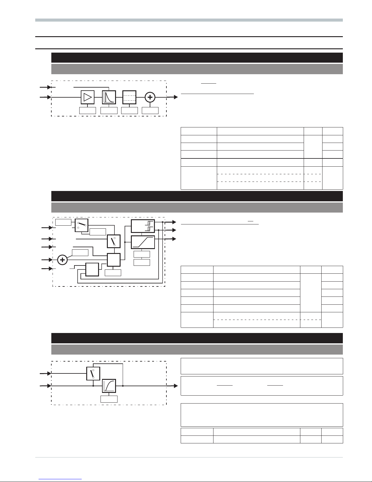
16 Limit signalling and limiting
16.1
ALLP
(alarm and limiting with fixed limits - no. 40)
Signal x1 is monitored for 2 low (L1, L2) and 2 high limit values
(H1, H2). Additionally min. and max. limiting is applied to the sig
-
nal (L1, H1). The signal can be x1 or dx1/dt or x1 - x0.
Parameter Description Values Default
H1
Max. alarm 1 or max. limit
Real
9999
L1
Min. alarm 1 or min. limit -9999
H2
Max. alarm 2 9999
y1 = signal limited to L1 and H1
z1 = 1 with signal > H1
z2 = 1 with signal > H2
z3 = 1 with signal < L1
z4 = 1 with signal < L2
L2
Min. alarm 2 -9999
x0
offset 0
xsd
switching hysteresis 1
Configuration Description Values Default
Select
Monitored variable: x1 0
0
Monitored var.: dx1/dt [1/s] 1
Monitored var.: x1 - x0 2
16.2 ALLV
(alarm and limiting with variable limits - no. 41)
Signal x1 is monitored for 2 low (x2, L2) and 2 high limit values
(x3, H2). Additionally min. and max. limiting is applied to the
signal (x2, x3). The signal can be x1 or dx1/dt or x1 - x0.
Parameter Description Values Default
H2
Max. alarm 2
Real
9999
L2
Min. alarm 2 -9999
y1 = signal limited to L1 and H1
x0
offset 0
z1 = 1 with signal > H1
xsd
switching hysteresis 1
z2 = 1 with signal > H2 Configuration Description Values Default
z3 = 1 with signal < L1
Select
Monitored variable: x1 0
0z4 = 1 with signal < L2 Monitored variable: dx1/dt [1/s] 1
Monitored variable: x1 - x0 2
16.3 EQUAL
(comparison - no. 42)
Checking, whether x1 is smaller, equal or higher than x2
(+/- tolerance Diff).
zwithxx
312
1=<\ e zz
63
=
zwithxx x
2122
1== +(\)( )eeK zz
52
=
zwithxx
112
1=>+e zz
41
=
Parameter Description Values Default
Diff
Tolerance limit Real 0
Mode
Source tolerance limit: Diff 0
0
Source of tolerance limit: x3 1
Limit signalling and limiting 9499-040-44311
ALLP 28
Select
H1 H2
L2
L1
x1
y1
z1
z2
z3
z4
Y1
h1
h2
l1
l2
Xsd
x0
Select
H2
L2
x1
x2
x3
y1
z1
z2
z3
z4
Y1
h1
h2
l1
l2
Xsd
X0
X1
H1
L1
Mode
Diff
x1
x2
x3
z1
z4
z2
z5
z3
z6
X1
X2
Diff
X1>X2
X1=X2
X1<X2
Page 29

16.4 VELO
(rate-of-change limiting - no. 43)
x1 is passed through to y1, however, its rate of change is limited to a
positive and / or a negative maximum value (gradient).
Parameter Description Values Default
GrX+
Positive gradient (1/s)
Real
Î
GrX-
Negative gradient (1/s) Î
Mode+
Source of pos. gradient: GrX+ 0
0
d1 = 0: positive gradient is effective
d2 = 0: negative gradient is effective
d1 / d2 = 1: relevant gradient is ineffective
Source of pos. gradient:x2 1
Mode-
Source of neg. gradient: GrX- 0
0
Source of neg. gradient: x3 1
16.5 LIMIT
(multiple alarm - no. 44)
x1 is checked for 8 alarm values. Mode determines the opera
-
tion of the relevant alarm (max. / min.).
Parameter Description Values Default
L1...L8
Alarm values
Real
0
Xsd
Switching hysteresis 0
z1...z8:0=noalarm 1 = alarm
Configuration Description Values Default
Mode1...
Mode8
Operation: max. alarm 0
0
Operation: min. alarm 1
16.6 ALARM
(alarm processing - no. 45)
x1 is checked for a low and a high alarm value. Additionally the digital
alarm input can be switched to d1. With d2 = 1 the alarms are sup
pressed. After removal of this signal, suppression is maintained, until
the monitored value returns within the limits.
z1:0=noalarm 1 = alarm Parameter Description Values Default
d1 can come e.g. from the fail output of an AINP
LimL
Low alarm value
Real
10
LimH
High alarm value 10
Lxsd
Switching difference 0
Configuration Description Values Default
Fnc
Alarm function: meas. value 0
0Alarm function: meas. value + d1 1
Alarm function: d1 2
9499-040-44311 Limit signalling and limiting
29 VELO
d2
d1
x1
x2
x3
y1
Mode+
GrX+
GrX+
Mode-
GrX-
GrX-
Î
Î
x1
L2 L8
L1
...
Mode1
Mode2 Mode8
...
z1
...
z8
Xsd
stop
fail
LimL
LimH
Xsd
d2
x1
d1
z1
Fnc
alarm
Page 30

17 Visualization
17.1
VWERT
(display / definition of process values - no. 96)
For display or alteration of 6 analog or digital values in 6
display lines. With d1 = 1 the operating page is not displayed.
With d2 = 1 the values are not adjustable by means of keys
ID. With a positive flank at d9 (0r1) the input values are
stored as output values.
Parameter Description Values Default
z1...z
6
Start values digital at po
-
wer-on
0/1 0
Y1...Y
6
Start values analog at po
-
wer-on
Real 0
Configurati
-
on
Disp1
...
Disp6
Display line, value adjustable 0
1Only display line 1
Line = Empty line 2
Mode1
...
Mode6
Display line analog 0
0
Display line digital 1
Dp1...
Dp6
Digits behind dec. point 0...5 0
Text entry is possible only via the engineering tool.
Header
The following values or texts are displayed in the lines:
Ü
Block number 3 digits
*
Fixed text or space (no access)
Ö
First 16 characters of ‘title’’
Analog line
ä
With analog lines: parameter name (dependent
of line
the first 6 characters of ‘text 1a’...’text 6a’)
#
With analog lines: value x1...x6 dependent of line
<
With analog lines: unit (the first 6 characters
Digital line
of ‘text 1b’...’text 6b’ dependent of line)
>
With digital lines: dependent of signal and line
the first 16 characters of ‘text 1a’...’text 6a’ (Signal=0)
the first 16 characters of ‘text 1b’...’text 6b’ (Signal=1)
Visualization 9499-040-44311
VWERT 30
x1
d3
x2
d4
x3
d5
x4
d6
x5
d7
x6
d8
d9
d2
d1
.
.
.
.
.
.
.
.
.
y1
z1
y6
z6
Mode 1
Mode 2
Mode 4
Mode 3
Mode 5
Mode 6
Dp1
z2
z3
z4
z5
z6 Y6
Dp2
Dp4
Dp3
Dp5
Dp6
Disp 1
A.A
?1
store
lock
hide
Disp 2
Disp 3
Disp 4
Disp 5
Disp 6
Y5
Y4
Y3
Y2
Y1z1
x1
x2
x3
x4
x5
x6
d1
d2
d3
d4
d5
d6
:
Ü* Ö
=
ä#<**
>*
Page 31

17.2 VBAR
(bargraph display - no. 97)
For display of 4 analog values, 2 thereof as bargraphs. The bar
graphs can be horizontal or vertical. The values of x1 and x2 can
also be altered. With d1 = 1 this operating page is not displayed.
With d2 = 1 the values are not adjustable using keys ID.
Parameter Description Values Default
Y1, Y2
display x1 / x2, variable Real 0
Configuration Description Values Default
Disp 1
Disp 2
display x1 / x2, variable 0
1only display x1 / x2 1
empty field x1 / x2 2
Dp1, DP2
Digits behind dec. point 0...3 0
Type
Both bargraphs horizontal 0
0
Both bargraphs vertical 1
Scaling bargraph 1 (x3)
X3 0
Left or bottom Real 0
X3 100
Right or top Real 100
X3 mid
Start value middle Real 0
Scaling bargraph 2 (x4)
X4 0
Left or bottom Real 0
X4 100
Right or top Real 100
X4 mid
Start value middle Real 0
Text entry is possible only via the engineering tool.
Bargraphs
horizontal
The following values or texts are displayed:
Ü
Block number 3 digits
*
Fixed text or space (no access)
Ö
First 16 characters of ‘title’
ä
Parameter name for x1 (first 6 characters of ‘name 1’)
#
Parameter name for x2 (first 6 characters of ‘name 2’)
<
Value x1
vertical
>
Value x2
y
Unit for x1 (first 6 characters of ‘unit 1’)
x
Unit for x2 (first 6 characters of ‘unit 2’)
9499-040-44311 Visualization
31 VBAR
x1
x3
x4 x2
x1
x3
x4
x2
x1
x2
x3
x4
d2
d1
y1
X4 0 X4 100
Typ
X3 100
y2
Y2
Dp2
Dp1
Disp 1
?1
Y1
X3 0 X3 mid
X4 mid
lock
hide
A.A
Disp 2
:
Ü* Ö
ä<y
#
>
x
:
Ü* Ö
ä
<>
yx
#
Page 32

17.3 VPARA
(parameter operation - no. 98)
For common display and adjustment of max. 6 parameters of ot
her function blocks on 6 display lines. When value 0 is specified
as block number, the corresponding line is a text line. With in
-
put (x) connected, keys ID are without effect but display and
output follow the input with positive edge at d3 (0r1). With d2
= 1, the values are not adjustable by means of keys ID. With
d1 = 1, the operating page is not displayed
Configuration Description Values Default
Block1...
Block6
Block number of
displayed parameter
**
Num1...
Num6
Parameter number
**
* To prevent confusion and thus operator errors, we
recommend adjusting block numbers and parameters
exclusively via the engineering tool, which is also used
for entry of the parameters with short-form descriptions
Text entry is possible only via the engineering tool.
The following values or texts are displayed in the lines:
Ü
Block number 3 digits
*
Fixed text or space (no access)
Ö
First 16 characters of ‘title’
ä
With parameter lines: parameter name (depend. of line
the first 6 characters of ‘text 1’...’text 6’)
Parameter line
#
With parameter lines: the parameter value
<
With parameter lines: unit (the first 6 characters
of ‘unit 1’...’unit 6’ dependent of line)
>
With text lines: the first 16 characters of
Text line
‘text 1’...’text 6’ dependent of line
Visualization 9499-040-44311
VPARA 32
x1
x2
x3
x4
x5
x6
d3
d2
d1
y1
y6
.
.
.
.
.
.
.
.
.
z1
z6
store
lock
hide
Block1
Num1
Num3
Num5
Num2
Num4
Num6
Block2
Block3
Block4
Block5
Block6
(1)
(2)
(3)
(4)
(5)
(6)
:
Ü* Ö
=
ä#<**
>*
Page 33

17.4 VTREND
(trend display - no. 99)
For collection and display of the last 100 analog values of x1.
These values are displayed in a trend curve. Sampling interval
(Sample) and time unit (Unit) are adjustable. With d1 = 1
the operating page is not displayed. With d2 = 1 sampling is in
terrupted. With d3 = 1 trend sampling is reset. Sampling can be
done automatically or with a positive pulse at d4.
Configuration Description Values Default
Unit of sampling interval
Unit
seconds ( s)0
0Minutes( m)1
Hours ( h)2
Sample
Value of sampling interval Real 1
Dp
Digits behind decimal point 0...3 0
X0
Display scaling 0%
Real
0
X 100
Display scaling 100% 100
Y1 is the value from 100 samples ago (X-100)
z1=1 when buffer memory full (ready)
The following values or texts are displayed:
Trend display
Ü Block number 3 digits
* Fixed text or space (no access)
Ö
First 16 characters of ‘title’
ä
X 100
#
X0
<
Instantaneous value x1
>
Unit for x1 (first 6 characters of ‘unit’)
y
-100*Sample, Unit
Text entry is possible only via the engineering tool.
9499-040-44311 Visualization
33 VTREND
X1
X1
Unit
-100
.
Sample
X0
x1
d3
d1
Y1
z1
d4
d2
Unit
Sample
sample
disabl
X-100
ready
reset
hide
...
98
99
100
1
2
3
4
X0 X 100
X 100
Dp1
A.A
:
Ü* Ö
ä
<
y
#
>
Page 34

18 Communication
ISO 1745
Max. 20 functions L1READ and L1WRIT are configurable (blocks 1...20), whereby any combination is possible. In the
functions, any data can be used.
18.1 L1READ
(read level1 data - no. 100)
Any 7 analog process values (x1...x7) and any 12 digital status
informations (d1...d12) of the engineering are composed into a
data set for the digital interface. With code 00, function num
ber 0, the digital interface can read the data set as overall
block or the individual values with codes 01...09, function
number 0.
18.2 L1WRIT
(write level1 data - no. 101)
With codes 31...39, function number 0, the digital interface
writes into EEPROM cells. The data set comprises 8 analog
process values (y1...y8) and 15 digital status informations
(z1...z15), which are thereby made available to the enginee
-
ring.
Communication 9499-040-44311
L1READ 34
Interface
x1
x7
...
Statusbyte1
Code 01
Code 02
Code 00
Code 03
Code 04
Code 05
Code 06
Code 07
Code 08
Code 09
6543210
d6
d1
...
Statusbyte2
6543210
d12
d7
...
Code 31
Code 32
Code 33
Code 34
Code 35
Code 36
Code 37
Code 38
Code 39
EEPROM
987654321043210
z1
z15
...
y1
.
.
.
.
.
.
.
y8
Interface
Page 35

PROFIBUS INTERBUS
Max. 4 functions DPREAD and 4 functions DPWRIT are configurable (blocks 1...4 or 11...14), whereby any combination
is possible. In the functions, any data can be used.
18.3 DPREAD
(read level1 data via PROFIBUS / INTERBUS - no. 102)
Block numbers 1...4. Any 6 analog process values (x1...x6) and
any 16 digital process values (d1...d16) of the engineering are
grouped for reading via a PROFIBUS/I
NTERBUS data channel.
Block number 1 provides the data for channel 1 etc. The
PROFIBUS/ I
NTERBUS module reads the data of two channels at
intervals of 100 ms. z1...z4 indicate the PROFIBUS/I
NTERBUS sta
-
tus.
z1 = bus access not successful
z2 = faulty parameter setting
z3 = faulty configuration
z4 = no data communication
18.4 DPWRIT
(write level1 data via PROFIBUS / INTERBUS - no. 103)
Block numbers 11...14. The data of a PROFIBUS/INTERBUS
data channel are transmitted into the memory. Block number
11 transmits the data of channel 1 etc. The
PROFIBUS/I
NTERBUS module writes the data of two channels
at intervals of 100 ms. The data set comprises 6 analog process values (y1...y6) and 16 digital status informations
(z1...z16), which are available to the engineering. z17...z21
indicate the PROFIBUS/I
NTERBUS status.
z17 = bus access not successful
z18 = faulty parameter setting
z19 = faulty configuration
z20 = no data communication
z21 = data OK
9499-040-44311 Communication
35 DPREAD
Interface
Statusbyte1
(0)
(1)
(2)
(3)
(4)
(5)
(6)
(7)
76543210
d8
d1
...
Statusbyte2
76543210
d16
d9
...
x1
.
.
.
.
.
x6
z1
z2
z3
z4
b-err
p-err
c-err
d-err
z1
z16
...
y1
.
.
.
.
.
y6
Interface
(0)
(1)
(2)
(3)
(4)
(5)
(6)
(7)
76543210
76543210
z17
z18
z19
z20
z21
b-err
p-err
c-err
d-err
valid
Page 36

19 KS98+ I/O extension
with CANopen interface
The additional CANopen interface extends the multi
-
function unit functionality already in the basic version by
w
Extension of the number of local I/O by means of
the modular PMA RM 200 I/O system
w
connection of PMA multi-temperature controllers
KS800 / KS 816 with CANopen interface
w
on-site data exchange with other KS98+ units (cross
crommunication)
a
These functions are available only in KS98+
versions from operating version 5.
BUS terminating resistor
Both ends (first and last unit) of the CANopen bus must be
fitted with a bus terminating resistor. For this purpose, the
bus terminating resistor provided in each KS98+ can be used.
With the S.I.L. switch closed, the terminating resistor is
connected. By default , the S.I.L. switch is open
(see opposite).
Status display : CAN bus status
Character Value Signification
1, 2 1...42 Node number
3, 4 : Separator
5, 6 NC NoCheck:
Node existence so far unchecked / node not provided.
Ck Check:
Check for node existence is busy.
NR NoResponse:
No response from this node. However, node is required.
OK Ready:
Node has responded and was identified.
ES EmStart:
Node has output an emergency message.
7, 10, 13 - Separator
8, 9 NA NotAvailable:
Node status is unknown.
PO PreOperation:
Node is in status PreOperational.
Er Error:
Node is in error condition.
Op Operational
: Node is in operational condition.
11, 12 NU NotUsed:
Node is not required by an own lib function.
Wa Waiting:
Lib function waits for identification of this node
Pa Parameter setting:
Lib function is busy setting the node parameters
OK Ready:
Lib function has finished parameter setting
14...21 String Determined node name
KS98+ I/O extension 9499-040-44311
DPWRIT 36
+24V
OUT
+24V
OUT
Error 1
Error 4
Error 2
Error 3
+24V
OUT
+24V
OUT
Iin1
0..20
mA
Iin2
0..20
mA
Iin4
0..20
mA
Iin3
0..20
mA
A-IN/I
RM220-0
Error 1
Error 4
Error 2
Error 3
NC
NC
NC
NC
I
in1
0..20
mA
Iin2
0..20
mA
Iin4
0..20
mA
Iin3
0..20
mA
A-IN/I
RM221-0
+24V
OUT
+24V
OUT
Error 1
Error 4
Error 2
Error 3
+24V
OUT
+24V
OUT
Iin1
0..20
mA
Iin2
0..20
mA
Uin4
-10..10
V
Uin3
-10..10
V
A-IN/I,U
RM222-2
Error 1
Error 4
Error 2
Error 3
+
-
+
-
4
3
+
-
+
-
2
1
A-IN/TEMP
RM224-1
GND
RxDTxD
Alarm
Receive
Power
Transmit
RTSB/PA/N
GNDGND
+5V
OUT
+24V
IN
P-DP-CPU
RM202
+24V
OUT
+24V
OUT
Error 1
Error 4
Error 2
Error 3
+24V
OUT
+24V
OUT
Iin1
0..20
mA
Iin2
0..20
mA
Iin4
0..20
mA
Iin3
0..20
mA
A-IN/I
RM220-0
Error 1
Error 4
Error 2
Error 3
NC
NC
NC
NC
I
in1
0..20
mA
Iin2
0..20
mA
Iin4
0..20
mA
Iin3
0..20
mA
A-IN/I
RM221-0
GND
RxDTxD
Alarm
Receive
Power
Transmit
RTSB/PA/N
GNDGND
+5V
OUT
+24V
IN
P-DP-CPU
RM202
open
Page 37

19.1 RM 211, RM212 and RM213 basic modules
An RM 200 system comprises a basic module (housing) for
mounting on a snap-on rail with 3, 5 or 10 sockets.
The left socket is generally reserved for bus coupler module
CANopen RM 201. Dependent of requirements, I/O modules or
dummies are fitted in the other sockets. The modules click
into the basic module and can be released for replacement by
means of simple tools.
a
The plug-in cards must not be plugged in or
withdrawn with the supply voltage switched on.
19.2 C_RM2x
(CANopen field bus coupler RM 201 - no. 14)
Coupler module RM201 contains the interface to the CAN bus and is plug
ged into the first socket. The other sockets are provided for various I/O
modules, which are read cyclically via an internal bus.
Parameter Description Values Default
NodeId
RM201 node address 2...42 32
Unlike other KS98 functions, only one data function may be wired at the ana
-
log outputs.
Prerequisite for communication between KS98+ multifunction unit and
CANopen field bus coupler RM 201 is a matching setting of CANparame
-
ters (r see ET98 r Device r CANparameters).
Outputs:
Slot1...Slot9 Connection of RM modules RM_DI, RM_DO, RM_AI and RM_AO
et-err 0 = no engineering error 1 = engineering error (change parameter NodeId)
id-err 0 = correct participant Id 1 = faulty participant Id
valid 0 = invalid data 1 = data are valid
9499-040-44311 KS98+ I/O extension
37 RM 211, RM212 and RM213 basic modules
CAN
H
GND
CAN
GND
RxD
CAN
L
TxD
Alarm
Receive
Power
Transmit
+24V
IN
CAN-CPU
RM 201
+24V
OUT
+24V
OUT
Error 1
Error 4
Error 2
Error 3
+24V
OUT
+24V
OUT
Iin1
0..20
mA
Iin2
0..20
mA
Iin4
0..20
mA
Iin3
0..20
mA
A-IN/I
RM 220-0
Error 1
Error 4
Error 2
Error 3
NC
NC
NC
NC
I
in1
0..20
mA
Iin2
0..20
mA
Iin4
0..20
mA
Iin3
0..20
mA
A-IN/I
RM 221-0
+24V
OUT
+24V
OUT
Error 1
Error 4
Error 2
Error 3
+24V
OUT
+24V
OUT
Iin1
0..20
mA
Iin2
0..20
mA
Uin4
-10..10
V
Uin3
-10..10
V
A-IN/I,U
RM 222-2
Error 1
Error 4
Error 2
Error 3
+
-
+
-
4
3
+
-
+
-
2
1
A-IN/TEMP
RM 224-1
Error 1
Error 2
+Ub
OUT
+Ue
IN
+Ue
IN
+Ub
OUT
-Ue
IN
-Ue
IN
-Ub
OUT
-Ub
OUT-USense
+U
Sense
+U
Sense
-U
Sense
DMS-IN
RM 225
A-OUT/A
Iout
0..20
mA
Uout
0..10
V
Iout
0..20
mA
Uout
0..10
V
Uout
0..10
V
Uout
0..10
V
Iout
0..20
mA
Iout
0..20
mA
I3
I2
I1
I4
U3
U2
U1
U4
RM 231-0
Iout
0..20
mA
Uout
-10..10
V
Iout
0..20
mA
Uout
-10..10
V
Uout
-10..10
V
Uout
V
-10..10
Iout
0..20
mA
Iout
0..20
mA
I3
I2
I1
I4
U3
U2
U1
U4
A-OUT/C
RM 231-2
IN2
IN1
IN4
IN3
IN4
IN3
IN2
IN1
+24V
OUT
+24V
OUT
+24V
OUT
+24V
OUT
D-IN/SEN
RM 241
OUT
3
OUT
1
OUT
4
OUT
2
6
4
2
OUT
7
OUT
5
OUT
8
OUT
6
8
5
3
1
7
+24V
IN
+24V
IN
Power
Power
D-OUT
RM 251
+24V
OUT
+24V
OUT
Error 1
Error 4
Error 2
Error 3
+24V
OUT
+24V
OUT
Iin1
0..20
mA
Iin2
0..20
mA
Iin4
0..20
mA
Iin3
0..20
mA
A-IN/I
RM 220-0
Error 1
Error 4
Error 2
Error 3
NC
NC
NC
NC
I
in1
0..20
mA
Iin2
0..20
mA
Iin4
0..20
mA
Iin3
0..20
mA
A-IN/I
RM 221-0
+24V
OUT
+24V
OUT
Error 1
Error 4
Error 2
Error 3
+24V
OUT
+24V
OUT
Iin1
0..20
mA
Iin2
0..20
mA
Uin4
-10..10
V
Uin3
-10..10
V
A-IN/I,U
RM 222-2
Error 1
Error 4
Error 2
Error 3
+
-
+
-
4
3
+
-
+
-
2
1
A-IN/TEMP
RM 224-1
GND
RxD TxD
Alarm
Receive
Power
Transmit
RTSB/PA/N
GNDGND
+5V
OUT
+24V
IN
P-DP-CPU
RM 202
+24V
OUT
+24V
OUT
Error 1
Error 4
Error 2
Error 3
+24V
OUT
+24V
OUT
Iin1
0..20
mA
Iin2
0..20
mA
Iin4
0..20
mA
Iin3
0..20
mA
A-IN/I
RM 220-0
Error 1
Error 4
Error 2
Error 3
NC
NC
NC
NC
I
in1
0..20
mA
Iin2
0..20
mA
Iin4
0..20
mA
Iin3
0..20
mA
A-IN/I
RM 221-0
GND
RxD TxD
Alarm
Receive
Power
Transmit
RTSB/PA/N
GNDGND
+5V
OUT
+24V
IN
P-DP-CPU
RM 202
Partial engineering for communication with a RM200 node.
Page 38

19.3 RM_DI
(RM 200 - digital input module - no. 15)
Function RM_DI handles the data of connected digital input modules.
Configuration Description Values
MTyp
Module type
0: RM 241 =4x24 VDC
1:RM242=8x24 VDC
2:RM243=4x230VAC
Inv 1
…
Inv 8
Direct or inverse output of input signal 1?
…
Direct or inverse output of input signal 8?
direct
/
inverse
Inputs and outputs:
Slot x Connection of one of the slot outputs of the RM 200 node (C_RM2x)
di 1...di 8 1st to 8th digital input signal
et-err 0 = no engineering error 1 = engineering error (several RM module functions in a slot)
slotid 0 = correct slot allocation 1 = faulty slot allocation (faulty RM module fitted)
valid 0 = no data 1 = data can be received
19.4 RM_DO
(RM 200 - digital output module - no. 16)
Function RM_DO handles the data of connected digital output modules.
Configuration Description Values
MTyp
Module type
0: RM 251 =8x24VDC,0,5A
1:RM252=4xrelay (230 VDC) 2A
Inv 1
…
Inv 8
Direct or inverse output of output signal 1?
…
Direct or inverse output of output signal 8?
direct
/
inverse
FStat1
Output last signal or Fstat in case of commu
-
nication failure
no
…
/
FStat8
FStat
FStat1
Output 1 status in case of errror 0/1
…
… ...
FStat8
Output 8 status in case of error 0/1
Inputs and outputs:
Slot x Connection of one of the slot outputs of the RM 200 node (C_RM2x)
do 1...do 8 Set-points for digital outputs 1 to 8
fail 1...fail 8 Output 1...output 8 with failure
et-err 0 = no engineering error 1 = engineering error (several RM module functions in a slot)
slotid 0 = correct slot allocation 1 = faulty slot allocation (faulty RM module fitted)
valid 0 = no data 1 = data could be received
KS98+ I/O extension 9499-040-44311
RM_DI 38
Page 39

19.5 RM_AI
(RM 200 - analog input module - no. 17)
Function RM_AI handles the data of connected analog input modules.
Configuration Description Values
Inputs and outputs:
MTyp
Modultyp
0: RM 221-0 = 4x 0/4...20 mA
1: RM 221-1 = 4x -10/0...10 V
2: RM 221-2 = 2x 0/4...20 mA + 2x -10/0...10 V
3: RM 222-0 = 4x 0/4...20 mA, TPS
4: RM 222-1 = 4x -10/0...10 V, potentiometer, TPS
5: RM 222-2 = 2x 0/4...20 mA + 2x -10/0...10 V,
potentiometer, TPS
6: RM224-1 = thermocouple / Pt100
7: RM224-0 = 2 x TC, 16 bits
8: RM224-2 = 1 x -3...3V, 1x TC, 16 bits
Slot x
Connection of one of the slot outputs of the
RM 200 node (C_RM2x)
AI 1...AI 4
1st to 4th input signal
et-err
0 = no engineering error
1 = enginee-ring error (several
RM module functions in a slot)
slotid
0 = correct slot allocation
1 = faulty slot allocation
(faulty RM module fitted)
valid
0 = no data
1 = data could be received
fail 1... fail 4
Measurement error at channel 1 … 4
(e.g. sensor break)
tcfail
Temperature compensation error
STyp 1
…
STyp 4
Input signal
1: type J = -120...1200°C
2: type K = -130...1370°C
3: type L = -120 ... 900°C
4: type E = -130...1000°C
5: type T = -130 ... 400°C
6: type S = 12...1760°C
7: type R = 13...1760°C
8: type B = 50...1820°C
9: type N = -109...1300°C
10: type W = 50...2300°C
30: Pt100 = -200 … 850°C
40: standard signal = 0...10V
41: standard signal = -10...10V
50: standard signal = 4...20mA
51: standard signal = 0...20mA
Unit 1
…
Unit 4
Temperature unit input 1 to 4
(only relevant with thermocouple and
Pt100 inputs)
0 : unit = °C
1 : unit = °F
2 : unit = K
Tf 1
…
Tf 4
Filter time constant input 1 … 4 in (s) 0 ... 200 000
Scaling
x0 1
…
x0 4
Scaling start value input 1 … input 4
-29 999 ...
200 000
x100 1
…
x100 4
Scaling end value input 1 ... input 4
-29 999 ...
200 000
9499-040-44311 KS98+ I/O extension
39 RM_AI
{
Page 40

19.6 Potentiometer connection and adjustment
Connection:
Modules RM 222-1 and RM222-2 are also suitable for connection of potentiometers.
Max. two potentiometers can be connected to module RM222-2 and max. four potentio
meters can be connected to module RM 222-1.
For potentiometer measurement, a voltage divider circuit is used. The channels designed
for voltage can be changed for potentiometer measurement pairwisely (by means of jum
-
pers on the module circuit board)
Uconst: Us = 5V DC (output instead of +24V OUT);
Short circuit proof current limiting: 20mA
Max. load: 4mA/channel; ] I ß 20mA (can be distributed to the 4 module channels.
The min. resistance values must be
4 x 1000 [ ,2x500[ or 1 x 250 [
Calibration
:
In order to calibrate the potentiometer inputs, call up menu item Calibration.
For this, leave the operating menu, call up
Main menu r Miscellaneous,
select Calibration, and call up the module you wish to calibrate.
Start by selecting the channel you wish to calibrate.
Press key I to select the channel number (chnl.1) and change it after acknowledgement via key M
Subsequently, press Quit and change over to Set 0% . Press key M. Set 0% starts flashing.
Bring the resistance value into the position for X0. The value valid for this channel appears on display X. Press key
M again to store this value as X0.
Actuate Set 0% and change over to Set 100%. Press key M. Set 100% starts flashing.
Now, bring the resistance value into the position for X100. The value valid for this channel appears on display X.
Press key M again to store this actual value as X100.
KS98+ I/O extension 9499-040-44311
Potentiometer connection and adjustment 40
123
5V U 1
456
5V U2
789
5V U 3
10 11 12
5V U4
RM222-1
RM222-2
only RM222-1
Page 41

19.7 RM_AO
(RM 200 - analog output module - no. 18)
Function RM_AO handles the data of connected analog output modules.
Configuration Description Values
MTyp
Modultype
0: RM 231-0 = 4x 0/4...20 mA / 4x 0...10 V
1: RM 231-1 = 4x 0/4...20 mA / 2x 0...10 V /
2x -10...10V
2: RM 231-2 = 4x 0/4...20 mA / 4x -10...10V
Inputs and outputs:
Slot x
Connection of one of the slot outputs of the
RM 200 node (C_RM2x)
OTyp 1
…
OTyp 4
Output
signal
10: standard signal= 0...10V
11: standard signal= -10...10V
20: standard signal= 0...20mA
21: standard signal= 4...20mA
AO 1...AO 4
1st to 4th analog output signal
et-err
x0 1
…
x0 4
Scaling 0% input 1 … input 4
-29 999 ...200 000
0 = no engineering error
1 = enginee-ring error
(several RM module functions in one slot)
slotid
x100 1
…
x100 4
Scaling 100% input 1 ... input 4 -29 999 ...200 000
0 = correct slot allocation
1 = faulty slot allocation
(faulty RM module fitted)
valid
0 = no data
1 = data could be received
fail 1... fail 4
Error channel 1 … 4
9499-040-44311 KS98+ I/O extension
41 RM_AO
Page 42

19.8 RM_DMS
strain gauge module
Function RM_DMS reads data from a special strain gauge module of KS98+ I/O exten
-
sion with CANopen. Max. 2 strain gauges can be connected to the module. The measu
red values are available at outputs AI 1 and AI 2.
The two measurements can be influenced via digital command inputs, e.g. zero setting.
Monitoring a new command ( positive flank at one of the digital inputs ) is restarted
only when the “ready” output is “1”. The module position in the RM rack is determined
by connection of analog input Slotx to the RM2xx node.
a
Important hint:
A special coupler module ( RM201-1 ) must be used for operation of the strain
gauge module. This coupler module cannot be combined with thermocouple
modules. Moreover, the limitations as for coupler module RM201 (e.g. max. 4
analog input modules) are applicable.
Digital inputs:
q
set_t1 Set tare strain gauge channel 1. The actual weight is not stored continuously as tare
(packaging weight). The following measurements provide the net weight.
q
res_t1 Reset tare strain gauge channel 1. The tare value is set to 0. Gross weight= net weight.
q
zero_1 Zero setting of strain gauge channel 1 measured value. The actual measured value is stored as a zero
value in a non-volatile memory.
q
set_t2 Set tare strain gauge channel 2. The actual weight is buffered as tare (packaging weight). The
following measurements provide net weight.
q
res_t2 Reset tare strain gauge channel 2. The tare value is set to 0. Gross weight=net weight.
q zero_2 Zero setting of the strain gauge channel 2 measured value. The actual measured value is stored as
zero in the non-volatile memory.
Digital outputs:
q
et-err 0 = no engineering error 1 = engineering error (several module blocks at a slot output).
slotx not connected.
q
slotId 0 = correct slot allocation 1 = faulty slot allocation (module type). faulty coupler module
q
valid 0 = no data 1 = data could not be received fail 1 faulty connection or measurement error on channel 1
fail 2 faulty connection or measurement error on channel 2 ready ready message after command handling
Analog inputs:
q
connection of one of the slot outputs of the RM201-1-node block
Analog outputs:
q
AI 1st measured value of strain gauge channel 1
q
AI 2nd measured value of strain gauge channel 2
Parameters:
MTyp 1/2 module type 0: RM225 = strain gauge
STyp 1/2 0: -4 +4mV/V
Unit 1/2 mV/V
Tf 1/2 filter time constant input 1 ... 2 in (s) 0 ... 999 999 (0,5 )
x0 1/2
scaling start value input 1 ... 2 -29 999 ... 999 999 (0)
x100 1/2 scaling end value input 1 ... 2 -29 999 ... 999 999 (100)
Fail 1/2 signal action in case of sensor error 0:upscale 1:downscale
X1in 1/2 measured value correction input value segment point 1 > input 1...2 -29 999 ... 999 999 (0)
X1out 1/2 measured value correction output value segment point 1 > input 1...2 -29 999 ... 999 999 (0)
X2in 1/2 measured value correction input value segment point 2 > input 1...2 -29 999 ... 999 999 (100)
X2out 1/2 measured value correction output value
KS98+ I/O extension 9499-040-44311
RM_DMS 42
Page 43

20 Cross communication KS 98plus - KS98plus
Whilst data exchange between KS 98+ and RM200, KS800 or KS816
must be carried out exclusively via KS98+ as a master, “cross commu
nication” is possible directly. Data exchange between several KS 98+
of a CAN network is via send blocks (CSEND; block numbers 21, 23, 25,
27) and receive blocks (CRCV; block numbers 22, 24, 26, 28).
In each send/receive block, max. 9 analog values and 16 digital statu
ses from the relevant engineering can be transmitted. The sender
sends the data together with his node address and block number.
The receiver checks, if the adjusted send address of the messages is
correct, and if the block number of the sender is by “1” lower than the
own one.
For BUS terminating resistor, see: 36
20.1 CRCV
(receive block numbers 22, 24, 26, 28 - no. 56)
Outputs:
Y1to Y9analog output values 1 to 9
Id-err
0 = correct bus participant Id
1 = faulty bus participant Id
valid
0 = no data
1 = data could be received
do 1... do l6 = status values 1 to 16
The CRCV function can receive data from another KS98+. The data of the
other multifunction unit are made available with the CSEND function. The
CSEND block number is by 1 smaller than the CRCV block number.
CRCV no. 22 reads the data of another KS98+ from CSEND no. 21
CRCV no. 24 reads the data of another KS98+ from CSEND no. 23
CRCV no. 26 reads the data of another KS98+ from CSEND no. 25
CRCV no. 28 reads the data of another KS98+ from CSEND no. 27
Configuration Description Values
NodeId
Node address of sending KS98+
(The sending KS98plus is adjusted accordingly in
window “CANparameters” in the engineering
tool, or in the device parameter via the front pa
-
nel (during off-line mode)
1...24
9499-040-44311 Cross communication KS 98plus - KS98plus
43 CRCV
open
22 24 26 28(,,)
Page 44

20.2 CSEND
(send block numbers 21, 23, 25, 27 - no. 57)
Function CSEND makes the data for other KS98+ available on the CANo
pen bus. The data can be read using the CRCV function by the other
multifunction units.
Configuration Description Values
delta
Change from which a new send
operation is started.
0.000...200 000
Inputs and outputs:
X1...X9
analog values 1 to 9, which are sent.
di 1...di 16
digital values 1 to 16, which are sent.
valid
0 = invalid data (e.g. no KS98+ but only KS98)
1 = data could be received
a
Transmission is at intervals of 200ms. Therefore, note that values which are applied only during 100 ms are lost.
Cross communication KS 98plus - KS98plus 9499-040-44311
CSEND 44
21 23 25 27
(
,,
)
Page 45

21 KS 800 and KS 816 connection
Function blocks C_KS8x and KS8x can be used for communicati
-
on between multifunction unitKS98+ and multi-temperature con
-
trollers KS 800 and KS 816.
Each KS 800 or KS 816 is allocated a node function C_KS8x.
The KS8x functions are allocated to the individual controllers
of KS 800 (max. 8 controllers) or KS 816 (up to 16 controllers).
For BUS terminating resistors, see page: 36
9499-040-44311 KS 800 and KS 816 connection
45 CSEND
open
Partial engineering for communication with the multi-temperature controllers KS800 and KS816
Page 46

21.1 C_KS8x
KS800 and KS 816 nodefunction - no. 58
Node function C_KS8x represents the interface to one of the multi-temperature
controllers KS 800 or KS 816. Analog outputs C1 … C16 can be used for connec
-
ting the KS8x functions which represent a controller of KS 800 (max. 8) or KS 816
(max. 16).
Parameter Description Values Default
NodeId
Node address of KS800/KS816 2...42 2
Unlike the other KS98 functions, only one data function may be wired at each ana
-
log output.
Prerequisite for a communication between the KS98+ multifunction unit and KS800
or KS816 is an identical setting of CANparameters (r see
*1)
).
Outputs:
C1...C16 Connection of KS8x functions (individual controller in KS800 / KS816)
et-err 0 = no engineering error 1 = engineering error (other node functions at equal KS800)
id-err 0 = correct bus participant Id 1 = faulty bus participant Id (no KS800/KS816 with the
configured node Id available)
valid 0 = no data 1 = data were received
online 0 = KS800/816 is offline 1 = KS800/816 is online
fail 1 0 = no fail at do1...do12 1 = fail at do1...do12
fail 2 0 = no fail at do13...do16 1 = fail at do13...do16
fail 3 0 = no heating current short circuit 1 = heating current short circuit
di1 0=di1=0 1=di1=1
di2 0=di2=0 1=di2=1
di3 0=di3=0 1=di3=1
di4 0=di4=0 1=di4=1
a
The data of the individual controllers are read cyclically.
All data are refreshed at the latest at intervals of 1,6 seconds (KS800) or of 3,2 seconds (KS816).
*1) The parameters for the CANopen bus are adjusted in window "CANparameters" in the engineering tool, or in
the instrument parameters viat the front panel. ET98 r Device r CANparameters.
KS 800 and KS 816 connection 9499-040-44311
C_KS8x 46
Page 47

21.2 KS8x
(KS 800 and KS 816 controller function - no. 59)
The KS8x functions each handle a controller from KS 800 or KS 816. The analog or
digital inputs can be used for sending the signals for control to the controller in
KS800/16.
The analog outputs provide the process and controller values.
Inputs and outputs:
Cx connection to one of the C1...C16 outputs of node function C_KS8x
W controller set-point
Yman correcting variable in manual mode
a/m 0 = controller is in automatic mode 1 = controller is in manual mode
C off 0 = controller is switched on 1 = controller is switched off
W/w2 0 = internal set-point is active 1 = 2nd set-point is active (safety set-point)
we/wi 0 = external set-point is active 1 = internal set-point is active
Ostart 0 = do not start self-tuning 1 = start self-tuning
X controller process value
Y controller correcting variable
St1 Status byte 1 Bit
Value Description
0 1 alarmHH
1 2 alarmH
2 4 alarmL
3 8 alarmLL
4 16 sensor fail alarm
5 32 heating current alarm
6 64 leakage current alarm
7 128 alarm DOx
St2 Status byte 2 Bit
Value Description
0 1 W2 active
1 2 Wint active
2 4 Wstart active
3 8 self-tuning active
4 16 self-tuning error
5 32 controller A / M
6 64 controller switched off
7 128 ----
et-err 0 = no engineering error 1 = engineering error (several KS8x control functions at a controller
channel)
valid 0 = no data 1 = data were received
xfail 0 = no sensor fail 1 = sensor fail
9499-040-44311 KS 800 and KS 816 connection
47 KS8x
Page 48

22 Description of KS98 CAN bus extension
22.1
CPREAD
(CAN-PDO read function)
Function CPREAD is used for read access to instrument PDOs. Due to the normal quantity
of min. 2 PDOs per instrument, the data quantity of 2 PDOs with 2 COB-IDs was grouped
in one block.
Node address and COB-ID (CAN-OBject IDentifier) parameter setting is in the block. Mo
reover, node guarding for monitoring the CAN communication to the specified node can
be switched on.
Data provided by the instrument must be interpreted according to the instrument specifi
cation. Groups of 4 transmitted bytes can be converted into different data types. For this
purpose, a conversion function for converting and inverting 1 to 4 bytes into a paramete
rizable data type (see function AOCTET) is available.
Examples: R1+R2 > Int16 / R1+R2+R3+R4 >Long
a
Important note: The heart beat protocol is not supported. If an instrument can be operated only via “heart beat”, the
guarding function must be switched off.
Digital inputs:
start The function is active with the input not connected, or if start=1 is connected.
Digital outputs:
et-err 0 = no engineering error
1 = no CAN-HW (KS98 type)
multiple node monitoring
id-err 0 = correct node id
1 = faulty node id or instrument does not reply
specify own node ID as “NodeId”
no free receive PDOs (RPDO)
valid Bit follows node status with the node guarding active
(0=”preoperational”, 1=”operational”)
always 1 with node guarding switched off
Analog outputs:
R1 1 ...R1 8 1st to 8th analog input value in byte format (8-bit) for COB-ID 1
R2 1 ...R2 8 1st to 8th analog input value in byte format (8-bit) for COB-ID 2
Configuration parameters (can be changed only during OFFLINE):
NodeId CAN node address
Guard node guarding off/on
COBID1 decimal ID of the first CAN object identifier
COBID2 decimal ID of the second CAN object identifier
Description of KS98 CAN bus extension 9499-040-44311
CPREAD 48
Page 49

22.2 CPWRIT
(CAN-PDO write function)
Function CPWRITE is used for write access to instrument PDOs. Because of the normal
quantity of min. 2 PDOs per instruments, the data quantity of 2 PDOs with 2 COB-IDs
was grouped in a block.
Node address and COB-ID (CAN-OBject IDentifier) parameter setting is in the block. Mo
reover, node guarding for monitoring the CAN communication to the specified node can
be switched on.
Data sent to the instrument must be interpreted according to instrument specification.
Groups of 4 transmitted bytes represent different data types.
To provide the bytes according to the required data type, a conversion function for trans
-
forming the value in the engineering into 1 to 4 bytes is available (see function AOCTET).
Examples: R1+R2 > Int16 / R1+R2+R3+R4 >Long
a
Important note: The heart beat protocol is not supported. If an instrument can be
operated only via “heart beat”, the guarding function must be switched off.
Digital inputs:
start The function is active, unless the input is connected, or if start=1 is connected.
Digital outputs:
et-err 0 = no engineering error
1 = no CAN-HW (KS98 type)
multiple node monitoring
id-err 0 = correct node id
1 = faulty node id or the instrument does not reply
own node ID was specified as “NodeId”
no free send PDOs (TPDO)
valid bit follows the node status with the node guarding active
(0=”preoperational”, 1=”operational”)
always 1 with the node guarding switched off
Analog outputs:
T1 1 ...T1 8 1st to 8th output value in byte format (8-bit) for COB-ID 1
T2 1 ...T2 8 1st to 8th analog output value in byte format (8-bit) for COB-ID 2
Configuration parameters (can be changed only during OFFLINE):
NodeId CAN node address
Guard node guarding off/on
COBID1 decimal ID of the first CAN object identifier
COBID2 decimal ID of the second CAN object identifier
9499-040-44311 Description of KS98 CAN bus extension
49 CPWRIT
Page 50

22.3 CSDO
CAN-SDO function
Function CSDO permits access to the CAN bus by means of SDOs (Service Data Ob
jects). SDOs are used for asynchronous data exchange without real-time inquiry.
Transmission started by the trigger input is always confirmed by the receiver, pos
-
sibly during data inquiry along with value transmission. Reception of the confirma
tion is indicated by a logic 1 at the “ready” output. A new command can be
generated via the positive flank at trig only with “1” indicated by the “ready” out
put.Data required for command generation can be adjusted as parameters or connec
-
ted as values to the inputs. As soon as a connection at an input was made, the re
-
levant parameter looses its function. In this case, the value applied to the input is
valid. Data (command) addressing in the connected instrument is done via indexes (index / sub-index), which is des
cribed in the CAN instrument documentation.
A value to be transmitted is connected to X1writ (or parameter “value”). A received value is output at Y1read. Y1read
is set to 0 after power-on, after an error ( “err”=1)andafter a data output.
With RM modules provided in the KS98 engineering, and for addressing the same nodes also via a CSDO block , the
trigger should be interlocked with the valid bit of the RM-200 block. During access to RM nodes which are handled
already by KS98 in the background, there may be start-up collisions the consequences of which are removed only by
restarting KS98.
a
Important note: The heart beat protocol is not supported. If an instrument can be operated only via “heart beat”, the
guarding function must be switched off.
Digital outputs:
err 0 = no error 1 = error detected.
Possible errors:
w
Faulty KS98 hardware. KS98+ expected.
w
The trigger input is not connected.
w
No reply or faulty reply from the instrument.
w
Instrument replies an inquiry with an error message.
w
Min. one parameter or connected value is out of limits.
ready 0 = transmission is being handled. So far, no confirmation was received.
1 = transmission completed. Ready for the next command.
Analog outputs:
T1 1 ...T1 8 1st to 8th analog output value in byte format (8-bit) for COB-ID 1
T2 1 ...T2 8 1st to 8th analog output value in byte format (8-bit) for COB-ID 2
Parameters (can be changed during operation):
Access access mode: 0 = read, 1 = write
NodeId decimal CAN node address,1..42
(KS98+ forms the CAN Object Identifier according to CiA DS301, node ID + 600H)
D-Type data type of the connected value, 0..6. The following data types are available
0: Uint8, 1: Int8, 2: Uint16, 3: Int16, 4: Uint32, 5: Int32, 6: Float
SubInd address in object directory 1..255
Index address in object directory 1..65535
Wert data value –29999 ... 999999)
Description of KS98 CAN bus extension 9499-040-44311
CSDO 50
Page 51

23 Programmer
Valid for DPROG and APROG:
With p-show = 1 and program in line Status, the direct parameter page can be indicated. It shows all
times and set-points belonging to a program. The marked line scrolls up and down and the values can be adjusted.
g
A new ProgNo is effective only after reset. After an engineering download Seg 0 is
output (reset). If run is not connected, stop is used. When sending a faulty recipe
number, Error is displayed.
The analog inputs and outputs of DPROG and APROG are determined as follows:
DBlock
Input DPROG / APROG: block number of the first data function DPROGD / APROGD
Input DPROGD / APROGD: block no. of the cascaded data function DPROGD / APROGD
Output DPROGD / APROGD: separate block number
ProgNo
Input: required program number; Output: actual program number
PSet
Input; preset value for program
SegNo
Output; actual segment number
TBrutt
Output; program time gross (] Trun + ] Tstop)
TNetto
Output; program time net (] Trun)
TRest
Output; rest time of programmer
WEnd
Output; final set-point of actual segment (only APROG)
Wp
Output; set-point of programmer (only APROG)
XVal
Input; value for search run (only APROG)
9499-040-44311 Programmer
51 CSDO
Page 52

23.1 APROG
(analog programmer - no. 24) / APROGD (APROG data - no. 25)
Direct parameter page Operator page
Data are contained in APROGD.
More than 10 segments:
cascade APROGD
several programs (recipes):
select APROGD via SELV2
d1 = 1: the operating page is
not displayed. d7 = 1: the direct
parameter page is indicated.
With d2 = 1 the values are not adjustable by means of keys ID.
d3: 0 = stop, 1 = run d4: 0 = continue, 1 = reset
d5: 1 = preset d6: 1 = search run
Reset has highest priority
A search run is carried out in the following cases:
w Start via front panel w Start via interface
w Start with d6 = 1 w Program start after Reset
w After short mains failure with PowerUp =1or2
When starting the search run set-point Wp is set to the value of Xval, from
where it reaches the segment end value with the actual gradient (TPrio =
0) or in the actual segment rest time (TPrio = 1). With the search value
outside the actual segment with TPrio = 0, the program is continued at the
point of the segment next to the search value (start / end of the actual segment). With segment start value = segment end value the program is continued at the segment start.
z1: 0 = program stop 1 = program running (Run) Parameter Description Values Default
z3: 1 = program end reached
WMode
Ramp function 0
0
z4: pressing key H toggles z4 (0 or 1) Step function 1
PMode
Preset to segment 0
1
Preset to time 1
TPrio
Gradient priority 0
0
Dependent of Turbo, Tp1...Tp10
for APROGD and DPROGD must be specified in
minutes or seconds in the engineering tool.
Time priority 1
Dp
Decimal points for setpoint 0..3 3
RecMax
Max. recipes 1..99 99
Wp0
Program setpoint after reset W0..W100 W0
W0
Lower setpoint range -29999 ...999 999 -29 999
W100
Upper setpoint range -29999...999 999 999 999
Configuration Description Values Default
PwrUp
Behaviour after mains recovery
Continue program 0
0Search run in actual segment 1
Continue at actual time 2
PEnd
After program end: stop 0
0
After program end: reset 1
Turbo
Time = hours : minutes 0
0
Time = minutes : seconds 1
Programmer 9499-040-44311
APROG 52
x1
x2
x3
x4
d1
d2
d3
d4
d5
d6
d7
PSet
DBlock
ProgNo
XVal
hide
lock
run
reset
preset
search
p-show
DBlock DBlock
y7
y1
.
.
.
.
.
.
z1
z2
z3
z4
run
reset
end
fkey
Wp
TNetto
TBrutt
TRest
SegNo
WEnd
ProgNo
x1
D
y1
Wp1
Wp2
Wp10
...
t
Tp1
Tp2 Tp10
...
PwrUp
Wp0
PMode Turbo
PEnd
WMode
TPrio
APROGD
A
A
D
weff
TRest
TNetto
wseg
ProgNo
SegNo
Status
111: Programm analog
Rec = 1
Wp0 = 550
Tp1 = 10:30
Wp1 = 600
Tp2 = 10:12
Wp2 = 800
program
Page 53

23.2 DPROG
(digital programmer - no. 27) / DPROGD (DPROG data - no. 28)
Data are contained in DPROGD. More
than 10 segments: DPROGD must be
cascaded, several programs (recipes):
select DPROGD via SELV2. d1 = 1: the
operating page is not displayed. d6 = 1:
the direct parameter page is displayed.
With d2 = 1 the values are not adjustable by means of keys ID.
d3: 0 = Stop, 1= Run d4: 0 = Continue, 1 = Reset d5: 1 = Preset
Reset has highest priority
Parameter Description Values Default
D0
Status of outputs 6...1 after reset 0 / 1 000000
RecMax
Max. recipes 1..99 99
PMode
Preset to segment 0 1
Preset to time 1
Configuration Description Values Default
PwrUp
Behaviour after mains recovery
Continue program 0 0
Continue at actual time 2
PEnd
Stop after program end 0 0
Reset after program end 1
Turbo
Time = hours : minutes 0 0
Time = minutes : seconds 1
The digital outputs are as follows:
z1: 0 = program stop 1 = program running (Run)
z2: 1 = program reset
z3: 1 = program end reached
z4: pressing key H toggles z4 (0 or 1)
D1...D10 for DPROGD must be specified as integer numbers consisting of ones and zeros in the engin. tool.
Ex.: 001101 specified as 1101, 000011 specified as 11.
9499-040-44311 Programmer
53 DPROG
x1
x2
x3
d1
d2
d3
d4
d5
d6
PSet
DBlock
ProgNo
hide
lock
run
reset
preset
p-show
DBlock DBlock
z1
z2
z3
z4
z5
...
z10
y1
y2
y3
y4
y5
run
reset
end
fkey
do1
...
do6
TNetto
TBrutt
TRest
SegNo
ProgNo
x1
D
y1
PwrUpPMode Turbo
PEnd
DPROGD
A
A
D
D1 D2 D10
...
t
Tp1
Tp2
Tp10
...
(32)
(16)
(8)
(4)
(2)
(1)
do6
do5
do4
do3
do2
do1
ProgNo
TRest
TNetto
do6...1
SegNo
Status
108: Programm digital
Rec = 1
D 0 = 000000
Tp1 = 10:30
D 1 = 001100
Tp2 = 10:12
D 2 = 101000
program
Direct parameter page Operator page
Page 54

24 Controllers
The analog inputs and outputs are determined as follows:
OVC+
Input; override control +
OVC-
Input; override control -
ParNo
Only with CONTR+; input: required parameter set; output: effective parameter set
W
Output; internal set-point
Weff
Output; effective set-point
Wext
Input; external set-point
X
Output; effective process value
X1
Input; main variable x1
X2
Input; auxiliary variable x2
X3
Input; auxiliary variable x3
XW
Output; control deviation
Y
Output; effective correcting value
Yadd
Input; additional correcting variable
Yhm
Input; correcting value with hard manual
Yout1
Output; correcting value yout1
Yout2
Output; correcting value yout2
Yp
Input; position feedback
The digital inputs and outputs are determined as follows:
a/m
Input or output; 0 = automatic 1 = manual
c fail
Output; 1 = controller in failure handling
d ovc+
Input; 1 = override control + with 3-point stepping controllers (exept PIDMA)
d ovc-
Input; 1 = override control - with 3-point stepping controllers (exept PIDMA)
dec
Input; 1 = decrement for manual adjustment
gr off
Input; 1 = suppression of set-point gradient
hide
Input;1=nodisplay of controller operating page
inc
Input; 1 = increment for manual adjustment
lock
Input; 1 = values can be altered neither with ID nor with inc / dec
o err
Output; 1 = error during self-tuning
o run
Output 1; 1 = self-tuning running
o stab
Output: 1 = process at rest (for self-tuning, exept PIDMA)
o-hide
Input;1=nodisplay of self-tuning operating page
off
Input or output; 0 = controller switched on 1 = controller switched off
ostart
Input; 1 = self-tuning start
oplock
Input;1=KeyÒ blocked
pi/p
Input or output; feedback/integrator 0 = with 1 = without (exept PIDMA)
rstart
Input; 1 = start set-point ramp
sm/hm
Input; 0 = soft manual 1 = hard manual
track
Input; 1 = tracking function on
w stop
Input; 1 = freeze effective set-point
w/w2
Input; 0 = int./ext. set-point1=W2
we/wi
Input or output; 0 = external 1 = internal set-point
xf
Input; sensor failure x1...x3
xw sup
Output; 1 = alarm suppression with set-point change
y/y2
Input or output; 0 = correcting valueY1=correcting value Y2
y1
Output; status of switching output Y1;0=off1=on
y2
Output; status of switching output Y2;0=off1=on
yp f
Input; sensor failure Yp
Controllers 9499-040-44311
DPROG 54
Page 55

24.1 CONTR
(control function - no. 90)
Page for self-tuning operator page
Controller with one con
trol parameter set. With
d1 = 1 the operating
page is not displayed.
With d2 = 1 the values
are adjustable neither
with keys ID nor with
d3 (z)/d4(u).
Parameter Description Values Default
W0
Min. set-point limit (Weff)
Real
0
W100
Max. set-point limit (Weff) 100
W2
Additional set-point 100
Grw+
Set-point gradient + (K/min)
Real
----
Grw-
Set-point gradient - (K/min)
----
Grw2
Set-point gradient W2 (K/min)
----
N0
Zero ratio control Real 0
a
Factor a (3-element control) Real 1
Xsh
Trigger point separation
Real
0,2
Tpuls
Min.pos.step time 0,3
Tm
Actuator response time 30
Xsd1
Switching difference signaller
Real
1
LW
Trigg.pnt.separ.add.contact
----
Xsd2
Switch.difference add.contact 1
Xsh1
Trigger point separation (PD)
Real
0
Xsh2
Trigger point separation (PD) 0
Y2
Additional correcting value Real 0
Ymin
Min. correcting variable limit
Real
0
Ymax
Max. correcting variable limit 100
Y0
Controller working point
Real
0
YOptm
Corr.value with proc.at rest 0
dYopt
Step height with self-tuning 100
Xp1
Proportional band 1
Real
100
Xp2
Proportional band 2 100
Tn
Integral time 10
Tv
Derivative time 10
Tp1
Cycle time heating 5
Tp2
Cycle time cooling 5
9499-040-44311 Controllers
55 CONTR
d1
d2
d3
d4
d5
d6
x7
d7
d16
x8
d18
d19
d20
y1
y5
z12
z3
z5
.
.
.
.
x1
x2
x3
x9
d15
d22
d14
d13
d12
d11
x5
x6
z9
z10
z11
d8
d9
x4
D
y6
y7
z1
z2
z4
z6
z7
w
A
d10
d21
d17
z8
y/y2
track
d ovcd ovc+
OVC+
OVC-
off
Yadd
y/y2
pi/p
o-hide
ostart
w/w2
we/wi
Wext
hide
lock
inc
dec
xf
yp f
Yp
a/m
sm/hm
Yhm
w stop
gr off
rstart
xw sup
c fail
a/m
Weff
X
Y
XW
W
Yout1
Yout2
off
y1
y2
we/wi
pi/p
o run
o stab
o err
OPT
Xp1
Xp2
Tn
Tv
Tp1
Tp2
W0 Grw+ Xsd1 Y2
W100 Grw- LW Y0
N0 Grw2 Xsd2 Ymin
a Tm Xsh1 Ymax
Tpuls Xsh Xsh2
xxxxx
x x xxx
xxxxx
xxxx xxx x
xx x
YOptm dYopt
OCond
Xn0 CFunc CMode COVC OMode
Xn100 CType CDiff WTrac Disp
SFac WFunc CFail Ratio XDp
xxxxx xxxxx xxxxx xxxxx
xx x
x
w2
xeff
weff(y)
y(xeff/xw
)
oplock
Page 56

Configuration Description Values Default Configuration Description Values Default
CFunc
Signallers:
9
WTrac
No tracking of Wint 0
01 Output 0 Set-point tracking 1
2 Outputs 1 Process value tracking 2
2-point controller 2
Ratio
Function of ratio controller:
0
3-point controller (x1 + N0) / x2 0
Heating/cooling switching 3 (x1 + N0) / (x1 + x2) 1
Heat.cont./cool.cont. 4 (x2 -x1 + N0) / x2 2
Heat.switch./cool.cont. 5
XDp
Digits beh.dec.pnt.(proc.v.) 0...3 0
2-point + add. contact * 6
Disp
Content of bargraph line:
0
3-pnt.stepping controller: Correcting variable 0
Standard 7 Control deviation 1
With position feedback Yp 8 Xeff 2
Continuous controller:
OMode
Self-tuning mode:
Standard 9 Standard 0 0
With split-range behaviour 10
OCond
Condition for process at rest:
0
With position feedback Yp 11 grad = 0 0
CType
Standard controller 0
0
grad <0 (controller inv.)
1
Ratio controller 1 grad >0 (controller dir.)
3-element controller 2 grad <>0 2
WFunc
Set-point control 0
0
Xn0
Span start
Real
0
Set-point/cascade control 1
Xn100
Span 100
CMode
Output action inverse 0
0
SFac
Factor stoichiom. ratio Real 1,00
Output action direct 1
CDiff
Differentiation Xw 0
0
Differentiation X 1
CFail
Behaviour with sensor failure:
1
Neutral 0
Ypid = Ymin (0%) 1
Ypid = Ymax (100%) 2
Ypid = Y2 (alteration
3
via front not possible)
Ypid = Y2 (automatic)
4
or Yman (manual mode)
COVC
No override control 0
0
Override-Control + 1
Override-Control - 2
Override-Control+/- 3
* Used as { / Y / OFF controller
Controllers 9499-040-44311
CONTR 56
Page 57

24.2 CONTR+
(extended control function - no. 91)
Page for self-tuning operator page
Controller with six con
trol parameter sets.
With d1 = 1 the operat
-
ing page is not dis
played. With d2=1the
values are alterable nei
-
ther with keys ID nor
with d3 (z)/d4(u).
Parameter Description Values Default
W0
Min. set-point limit (Weff)
Real
0
W100
Max. set-point limit (Weff) 100
W2
Additional set-point 100
Grw+
Set-point gradient plus
Real
----
Grw-
Set-point gradient minus
----
Grw2
Set-point gradient for W2
----
N0
Zero ratio control Real 0
a
Factor a (3-element control) Real 1
Xsh
Trigger point separation
Real
0,2
Tpuls
Min.pos.step time 0,3
Tm
Actuator response time 30
Xsd1
Switching difference signaller
Real
1
LW
Trigg.pnt.sep.add.contact
----
Xsd2
Switch.difference add.contact 1
Xsh1
Trigger point separation (PD)
Real
0
Xsh2
Trigger point separation (PD) 0
Y2
Additional correcting value Real 0
Ymin
Min. output limiting
Real
0
Ymax
Max. output limiting 100
Y0
Controller working point
Real
0
YOptm
Correct.value w.process at rest 0
dYopt
Self-tuning step height 100
POpt
Parameter set to be optimized 1...6 1
Xp1 1...6
Proportional band 1
Real
100
Xp2 1...6
Proportional band 2 100
Tn 1...6
Integral time set 10
Tv 1...6
Derivative time set 10
Tp1 1...6
Cycle time heating 5
Tp2 1...6
Cycle time cooling 5
9499-040-44311 Controllers
57 CONTR+
d1
d2
d3
d4
d5
d6
x7
d7
d16
x8
d18
d19
d20
z12
z3
z5
x1
x2
x3
x9
d15
d14
d13
d12
d11
x5
x6
x9
z9
z10
z11
d8
d9
x4
D
z7
w
A
d10
d17
y8
z8
y/y2
track
d ovcd ovc+
OVC+
OVC-
ParNo
off
pi/p
ostart
w/w2
we/wi
Wext
hide
lock
inc
dec
xf
yp f
Yp
a/m
sm/hm
Yhm
w stop
gr off
rstart
we/wi
ParNo
pi/p
orun
ostab
oerr
OPT
Xp1 1 Xp1 6
Xp2 1 Xp2 6
Tn 1 Tn 6
Tv 1....Tv 6
Tp1 1 Tp1 6
Tp2 1 Tp2 6
xxxx
xxxx
xxxx
xxxx
xxxx
W0 Grw+ Xsd1 Y2
W100 Grw- LW Y0
N0 Grw2 Xsd2 Ymin
a Xsh1 Ymax
Xn0 Xsh2 Xsh
Tm Tpuls
xxxxx
x x xxx
xxxxx
xxxx xxxxx x
xx xxxxx x
xxxxx xxxxx xxx
YOptm dYopt POpt
OCond
Xn0 CFunc CMode COVC OMode
Xn100 CType CDiff WTrac Disp
SFac WFunc CFail Ratio XDp
xxxxx xxxxx xxxxx xxxxx
xx x
x
w2
d21
Yadd
o-hide
xeff
ParNo
weff/y
xeff/xw/y
y6
y7
z1
z2
z4
z6
y/y2
Yout1
Yout2
off
y1
y2
y1
y5
.
.
.
.
xw sup
cfail
a/m
Weff
X
Y
XW
W
Page 58

Configuration Description Values Default Configuration Description
Value
s
Default
CFunc
Signaller:
9
WTrac
No tracking of Wint 0
01 Output 0 Set-point tracking 1
2 Outputs 1 Process value tracking 2
2-point controller 2
Ratio
Function of ratio controller:
0
3-point controller: (x1 + N0) / x2 0
Heating/cooling switching 3 (x1 + N0) / (x1 + x2) 1
Heat. cont./cool. switch. 4 (x2 -x1 + N0) / x2 2
Heat. switch./cool. cont. 5
XDp
Digits beh. dec.pnt.(proc.v.) 0...3 0
2-point + add. contact * 6
Disp
Content of bargraph line:
0
3-point stepping controller: Correcting variable 0
Standard 7 Control deviation 1
With position feedback. Yp 8 Xeff 2
Continuous controller:
OMode
Self-tuning mode:
Standard 9 Standard 0 0
With split-range behaviour 10
OCond
Condition for process at rest:
0
With position feedback Yp 11 grad = 0 0
CType
Standard controller 0
0
grad <0 (controller inv.)
1
Ratio controller 1 grad >0 (controller dir.)
3-element controller 2 grad <>0 2
WFunc
Set-point control 0
0
Xn0
Span start
Real
0
Set-point/cascade control 1
Xn100
Span 100
CMode
Output action inverse 0
0
SFac
Factor stoichiom. ratio Real 1,00
Output action direct 1
CDiff
Differentiation Xw 0
0
Differentiation X 1
CFail
Behaviour with sensor failure:
1
Neutral 0
Ypid = Ymin (0%) 1
Ypid = Ymax (100%) 2
Ypid = Y2 (alteration
3
via front not possible)
Ypid = Y2 (automatic)
4
or Yman (manual)
COVC
No override control 0
0
Override-Control + 1
Override-Control - 2
Override-Control+/- 3
* Used as { / Y / OFF controller
Controllers 9499-040-44311
CONTR+ 58
Page 59

24.3 PIDMA
(controller function, No.93)
Self optimization page operating page
Controller with one
set of control param
eters. With d1=1the
operating page is not
shown. With d2 = 1
the values are neither
with ID keys nor
with d3 (z)/d4(u)
adjustable.
Parameter Description Values Default
PType
Line type (
with/without Compensation) 1/2 1
Drift
Drift compensation on/off 0/1 0
CSpeed
Control dynamic
slow/normal/fast 1...3 1
W0
Min. set-point limit (Weff)
Real
0
W100
Max. set-point limit (Weff) 100
W2
Additional set-point 100
Grw+
Set-point gradient + (K/min)
Real
----
Grw-
Set-point gradient - (K/min)
----
Grw2
Set-point gradient for W2 (K/min)
----
N0
Zero ratio control Real 0
a
Factor a (3-element control) Real 1
TPause
Min pause duration
Real
0,1
Tpuls
Min.pos.step time 0,3
Tm
Actuator response time 30
thron
Switch-on point of step. output
Real
0.2
throff
Switch-off point of step. output 0.2
Y2
Additional correcting value Real 0
Ymin
Min. output limiting
Real
0
Ymax
Max. output limiting 100
Y0
Controller working point
Real
0
dYopt
Self-tuning step height 20
Xlimit
Switch-off point for dYopt
Real
10
Tdrift
Drift estimation time 30
Tnoise
Noise estimation time 30
Kp
Control gain
Real
1
Tn
Integral time set 10
Tv
Derivative time set 10
Tp1
Cycle time heating 5
Tp2
Cycle time cooling 5
VD
Derivative gain 4
bW_p
Set-point weighing factor p-part 1
cW_d
Set-point weighing factor d-part 0
Tsat
Time constant "Anti reset wind up" 50
Xsh
Trigger point separation 0
9499-040-44311 Controllers
59 PIDMA
d1
d2
d3
d4
d5
d6
x7
d7
d13
x8
d15
d16
d17
y1
y5
z10
z3
z5
.
.
.
.
x1
x2
x3
x9
d12
d19
d11
d10
x5
x6
z8
z9
d8
d9
x4
D
y6
y7
z1
z2
z4
z6
z7
w
A
d18
d14
y/y2
track
OVC+
OVC-
off
Yadd
y/y2
o-hide
ostart
w/w2
we/wi
Wext
hide
lock
inc
dec
xf
yp f
Yp
a/m
sm/hm
Yhm
w stop
gr off
rstart
xw sup
c fail
a/m
Weff
X
Y
XW
W
Yout1
Yout2
off
y1
y2
we/wi
o run
o err
OPT
Xp1
Xp2
Tn
Tv
Tp1
Tp2
W0 Grw+ Xsd1 Y2
W100 Grw- LW Y0
N0 Grw2 Xsd2 Ymin
a Tm Xsh1 Ymax
Tpuls Xsh Xsh2
xxx x x
x x xxx
xxx x x
xxxx xxx x
xx x
OPt.Parameter
Xn0 CFunc CMode COVC OMode
Xn100 CType WTrac Disp
SFac WFunc CFail XDp
xxxxx xxxxx xxxxx xxxxx
xx x
x
Ratio
w2
xeff
weff(y)
y(xeff/xw
)
oplock
Page 60

Configuration Description Values Default Configuration Description Values Default
Controller type-selction:
WTrack
Tracking-Funktion
0
CFunc
2-point controller 0
1
No tracking of Wint 0
Continuous controller Set-point tracking 1
Standard 1 Process value tracking 2
With position feedback. Yp 8
Ratio
Function of ratio controller:
0
3-point controller: (x1 + N0) / x2 0
Heating/cooling switching 2 (x1 + N0) / (x1 + x2) 1
Heat. cont./cool. switch.
3 (x2 -x1 + N0) / x2 2
Heat. switch./cool. cont.
4
XDp
Digits beh. dec.pnt.(proc.v.) 0...3 0
Heat. cont./cool. cont. 5
Disp
Content of bargraph line:
0
3-point stepping controller: Correcting variable 0
Standard 6 Control deviation 1
With position feedback. Yp 7 Xeff 2
Xn0
Span start Real 0
CType
Standard controller 0
0
Xn100
Span Real 100
Ratio controller 1
SFac
Factor stoichiom. ratio Real 0
3-element controller 2
WFunc
Set-point control 0
0
Set-point/cascade control 1
CMode
Output action inverse 0
0
Output action direct 1
CFail
Neutral 0
Ypid = Ymin (0%) 1
Ypid = Ymax (100%) 2
Ypid = Y2 (alteration
3
via front not possible)
Ypid = Y2 (automatic)
4
or Yman (manual)
COVC
No override control 0
0
Override-Control + 1
Override-Control - 2
Override-Control+/- 3
Controllers 9499-040-44311
PIDMA 60
Page 61

25 Inputs
25.1
AINP1
(analog input 1 - no. 110)
For direct connection of temp. sensors, for resist. transducers and standard signals
For INP1 configuration and parameter setting. Block number 61,
calculated once per time slot.
Parameter Description Values Default
x1in
Meas.value correction P1, input
Real
0
x1out
Meas.value correction P1, output 0
x2in
Meas.value correction P2, output 100
x2out
Meas.value correction P2, output 100
Configuration
Description Values Default
Typ
Type L -200...900 °C 00
30
Type J -200...900 °C 01
Type K -200...1350 °C 02
Type N -200...1300 °C 03
calibration
Type S -50...1760 °C 04
x1, z2, z3, z4 are used for resistance transducer
Type R -50...1760 °C 05
or line calibration with 2x Pt100 (r section
Type T -200...400 °C 06
Menus, Calibration). With d2 = 1 this calibration
Type W 0...2300 °C 07
is disabled, with d1 = 1 the calibration page is not
Type E -200...900 °C 08
displayed. With fail , z1 = 1 (sensor failure).
Type B 0...1820 °C 09
Pt 100 -99,9...850,0 °C 20
Pt 100 -99,9...250,0 °C 21
2x Pt 100 -99,9...850 °C 25
2x Pt 100 -99,9...250,0 °C 26
0...20 mA 30
4...20 mA 31
0...10 V 32
2...10 V 33
Transducer 0...500 [ 40
Resistance 0...500 [ linear 45
Resistance 0...250 [ linear 46
Fail
Fail function off 0
1
z1=1,y1=x100 1
z1=1,y1=x0 2
z1=1,y1=XFail 3
Xkorr
Meas.value correction off 0
0
Correction adjustable 1
Unit
Unit = °C 1
1
Unit = °F 2
STK
Int. temperature compensation 1
1
Ext. temperature compensation 2
x0
Physical value at 0%
Real
0
x100
Physical value at 100% 100
XFail
Substitute value with sensor fail 0
Tfm
Filter time constant [s] 0,5
Tkref
Refer. temperature with STK=2 0
9499-040-44311 Inputs
61 AINP1
x1
d2
d1
z4
z3
z2
z1
y1
Unit
STK
Tkref
Typ
XFail
Failx0x100
Tfm
x2out
Xkorr
x2in
x1out
x1in
y
lock
hide
dec
inc
hand
fail
Cal
Page 62

25.2 AINP3...AINP6
(analog inputs 3...6 - no. 112...115)
g
For connection of standard signals, AINP6 also for resistance transducers,
AINP3 also for dc voltage -50...1300 mV (9407-9xx-x2xx1)
For INP3...INP6 configuration and parameter setting. Block num
-
bers 63...66, calculated once per time slot.
AINP
Parameter Description 3456Values Def
x1in
Correction P1; input
ffff
Real
0
x1out
Correction P1; output
ffff
0
x2in
Correction P2; input
ffff
10
0
x2out
Correction P2; output
ffff
10
0
AINP
Configuration
Description
3456
Values Def
With fail, z1 = 1 (sensor failure).
Typ
0...20 mA *
ffff
30
30
4...20 mA
ffff
31
x1, z2, z3 and z4 are used for transducer calibration
0...10 V — —f—32
(AINP6, r section Menus, Calibration). With
2...10 V — —f—33
d2 = 1 this calibration is disabled, with d1=1the
Transducer 0..1000 [ ———
f
40
calibration page is not displayed.
Fail
Fail function off
ffff
0
1
z1=1,y1=x100
ffff
1
z1=1,y1=x0
ffff
2
* 9407-9xx-x2xx1, AINP3:
With Type = 0...20 mA, the input is designed for
-50...1300 mV. For further use of the output of
INP3 with this scaling, an x0 of -50 and an x100
of 1300 must be adjusted.
z1=1,y1=XFail
ffff
3
Xkorr
Meas.val. correct. off
ffff
0
0
Correction adjustable
ffff
1
x0
Phys. value at 0%
ffff
Real
0
x100
Phys. value at 100%
ffff
10
0
XFail
Subst. val. at fail
ffff
0
Tfm
Filter time const. [s]
ffff
0,5
25.3 DINPUT
(digital inputs - no. 121)
For di1...di12 configuration and parameter setting (di3...di12 are
hardware-dependent). Block number 91, calculated once per
time slot.
Configuration Description Values Default
Inv1...
Output direct (z = di) 0
0
Inv12
Output inverse (z = di
)1
Inputs 9499-040-44311
AINP3...AINP6 62
x1
d2
d1
z4
z3
z2
z1
y1
Unit
Typ
XFail
Failx0x100
Tfm
x2out
Xkorr
x2in
x1out
x1in
y
lock
hide
dec
inc
hand
fail
Cal
HARDWARE
SOFTWARE
di1
di2
di3
di4
...
di12
z1
z2
z3
z4
...
z12
Inv1
Page 63

26 Outputs
26.1
OUT1...OUT5
(process outputs 1...5 - no. 116...120)
For OUT1...OUT5 configuration and parameter setting. Block
numbers 81...85, calculated once per time slot.
OUT
Configuration Description 1/2 3 4/5 Values Def.
Src
Sign. source: d1
(digital)
fff
0
0
Sign. source: x1
(analog)
fff
1
Operating principle:
Mode
Direct/norm. open
fff
0
0
Inverse/norm. closed
fff
1
Continuous output:
Type
Logic 0/20 mA
ff
—0
1
0...20 mA
ff
—1
4...20 mA
ff
—2
Input:
x0
Value of x1 at 0%
fff
Real
0
x100
Value of x1 at 100%
fff
100
26.2 DIGOUT
(digital output - no. 122)
For configuration of DO1...DO6 (dependent of hard- ware). Block
number 95, calculated once per time slot.
Configuration Description Values Default
Mode1
...
Output direct (do = d) 0
0
Mode6
Output inverse (do = d
)1
9499-040-44311 Outputs
63 OUT1...OUT5
HARDWARE
SOFTWARE
Relais
Logik
0..20mA
4...20mA
d1
x1
OUT1
OUT2
OUT1
OUT2
Src
x0
x100
Type
Mode
HARDWARE
SOFTWARE
Logik
0..20mA
4...20mA
d1
x1
OUT3
Src
x0
x100
Type
Mode
HARDWARE
SOFTWARE
Relais
d1
x1
OUT4
OUT5
Src
x0
x100
Mode
HARDWARE
SOFTWARE
d1
d2
d3
d4
d5
d6
do1
do2
do3
do4
do5
do6
Mode1
Page 64

27 Zusatzfunktionen
27.1
LED
(LED display - no. 123)
For configuration of the four LEDs.
Block number 96, calculated once per time slot.
Parameter Description Values Default
Inv1...
No inversion (LED = d) 0
0
Inv4
Inversion (LED = d
)1
27.2 INFO
(information function - no. 124)
For configuration of 12 user texts each with max. 16 characters.
Block number 97, calculated once per time slot. If the relevant
input is 1, the relevant text is displayed.
Parameter Description
Text1...
User texts each with max. 16 alphanumeric
characters. Default:
>INFORMATION XX<
Text12
27.3 STATUS
(status function - no. 125)
Block number 98, updated once per time slot.
d1=1: parameters/configurations are not displayed
d2=1: configurations are not displayed
d3=1: the main menu is not displayed, only operating
pages are displayed during on-line operation
d4=1: the use of the bus interface is blocked
z1...z4:Infos from status byte 2 (signification as d1...d4)
z5=0: S.I.L. switch open, z5=1: switch closed
z6=1: common message sensor failure
z7: safety status, set via interface
(code 22, fbno. 0, fctno. 0)
z8: power fail check, z8=0 after power ON
z9: after off-line r on-line to 1 during 1600 ms
Y1...Y6: status of real-time clock (if provided)
Y7=0: language German, Y7=1: language English
(selected with Miscellaneous, Device
data)
Zusatzfunktionen 9499-040-44311
LED 64
d1
d2
d3
d4
Inv1
Inv2
Inv3
Inv4
¬
¬
¬
¬
LED 1
LED2
LED3
LED4
>INFORMATION 1<
d1
.
.
.
.
.
.
.
.
.
.
.
d12
Statusbyte2
6543210
Statusbyte1
6543210
d2
d1
d3
d4
d5
d6
z2
z1
z3
z4
z6
z7
z8
z5
z9
y1
y2
y3
y4
y5
y6
y7
y8
z10
z11
z12
?1
?1
?1?1?1
?1
c-hide
p-hide
Minute
Hour
Day
Month
Year
Week-D
Langu.
n.c.
n.c.
n.c.
n.c.
fail
safe
pwrchk
switch
start
c-hide
p-hide
m-hide
b-lock
m-hidem-hidem-hide
b-lock
n.c.
n.c.
S
Interface
InterfaceInterfaceInterface
Interface
Interface
OnLine
OffLine
1600ms
Language
Page 65

27.4 CONST
(constant function - no. 126)
16 analog values and the logic levels 0 and 1 are made availa
-
ble. Block number 99, configured firmly once.
Parameter Description Values Default
C1...
C16
Analog constants Real 0
27.5 SAFE
(safety function - no. 94)
For generation of 8 defined analog output values and digital le
-
vels. With d9=1ORbit2,status byte1 = 1 the configured data
z1...z8 and Y1...Y8, otherwise the data applied to inputs
d1...d8 and x1...x8 are output.
Bit 2 can be set via the interface (code 22, fbno. 0, fctno. 0).
Parameter Description Values Default
Y1...Y8
Analog values Real
0
z1...z8
Digital levels 0/1
9499-040-44311 Zusatzfunktionen
65 CONST
z1
z2
0
1
y1
...
y16
C1
d1
...
d8
d9
x1
...
x8
z1
...
z8
y1
...
y8
Y1 Y2 Y3 Y4
Y5 Y6 Y7 Y8
d1 d2 d3 d4
d5 d6 d7 d8
?1
select
Statusbyte1
6543210
Page 66

28 KS98 I/O extension modules
For mounting in KS98: 9407 - 9xx - x3xx1 and
9407 - 9xx - x4xx1.
Safety hints
l
ESD !
contains electrostatically sensitive
components
-Original packing protects against
electrostatic discharge (ESD).
-Transport only in original packing.
During mounting, rules for ESD protection
must be taken into account.
Connection:
-KS98 engineering must be ta
-
ken into account, because it de
termines pin allocation and
signification of connections.
Maintenance:
No particular maintenance is required for the units.
a
When opening the units, live parts can be exposed.
Before work, disconnect the supply voltage.
The units contain electrostatically sensitive
components.
I/O modules 9407-998-00xx1
Module type:
Analog inputs:
Pt 100 / 1000, Ni 100 /1000, 2 0
Resistance, potentiometer
Thermocouple, mV, 0/4..20mA 2 1
-50...1500mV, 0...10V 2 2
Analog outputs:
1)
0/2...10V, 0..._10V 3 0
0/4...20mA, 0..._20mA 3 1
Digital inputs/outputs:
Digital I/O (universal) 4 0
Frequency/counter input 4 1
1)
PERFORMANCE LIMITS
For reasons of maximum permissible self-heating, the number of possible analog output modules per basic card is limited: Max. one current output modu
-
le! Max. one voltage output module, if a current output module is already provided (but in different galvanically isolated module groups)! The sum of per
-
formance factors (P factor, r Technical data) must not exceed 100%! If 100% are exceeded, a message is output in the Engineering Tool. Unless a
current output module is used, modules of any type can be fitted on all sockets. Max. 1 current outputmodule (any socket)! Max. 1 current and max.1 volta
ge output module, but on galvanically isolated sockets!
Example: Current output module in socket 1 or 2 and voltage output module in sockets 3 or 4. The sum of P factors is 95%. 1 more resistance or 1
TC/mV/mA module can be fitted.
2)
Galvanic isolation: sockets 1-2 are galvanically isolated from 3-4.
KS98 I/O extension modules 9499-040-44311
SAFE 66
a
b
(Block no.) (70) (69) (68) (67)
Socket
2)
43 21
00201
R_Inp
8368
00201
R_Inp
8368
The various modules
are distinguished by
printed label.
The last 5 digits of
the ordernumber are
given in the upper
line.
Mounting
After releasing the locking screw, withdraw the KS98 module
from the housing. (a) - Insert the module into the required
socket with the printed label pointing downwards into
the green connector and click it in position in the small,
white contact (b) at the top.
00201
R_Inp
8368
Page 67

28.1 Electrical connections of modular option C
Resistive input
(9407-998-0x201)
4-wire 3-wire 2-wire potentiometer
TC, mV, mA / V inputs
(9407-998-0x211) /
(9407-998-0x221)
Voltage /
current outputs
(9407-998-0x301) /
(9407-998-0x311)
Combined digital inputs/
outputs
(9407-998-0x401)
Frequency/
Counter inputs
(9407-998-0x241)
Quadruple counter up/down counter 2 x counter and 2 x frequency
Connect acc. to engineering!
(print-out with ET/KS 98plus)
Connection of
basic unit
socket 1
(block 67)
socket 2
(block 68)
socket 3
(block 69)
socket 4
(block 70)
9499-040-44311 KS98 I/O extension modules
67 Electrical connections of modular option C
_
_
_
_
_
_
U1
I1
U2
I2
I1
I2
+
+
+
+
+
+
di 1/2 (-)
di 2 (+)
di 1 (+)
do 1/2 (-)
do 2
do 1
do1/2(+)
_
_
U1
U2
+
+
+
+
R1
R1
R1
R2
R1
R2
}2
}1
di 2 (+)
di 1 (+)
di 1/2 (-)
di 2 (+)
di 1 (+)
di 1/2 (-)
di 2 (+)
di 1 (+)
di 1/2 (-)
di 2 (+)
di 1 (+)
di 1/2 (-)
V
V
1
2
3
4
5
6
7
8
9
10
11
12
13
14
15
16
C
ABCP
1
16
1
16
OUT
IN
INTERBUS
AB
Page 68

29 Modular I/O extension modules
29.1
TC_INP
(analog input card TC, mV, mA, No. 46)
Analog input, plugs into modular option card C
For configuration and parameter setting of analog inputs R_INP. The inputs
are invariably calculated once per time slot.
Parameter Description Values Default
x1a in
Measured value correction Inp_a, P1 Input value
Real
0
x1aOut
Measured value correction Inp_a, P1 Output value 0
x2a in
Measured value correction Inp_a, P2 Input value 100
x2aOut
Measured value correction Inp_a, P2 Output value 100
x1b in
Measured value correction Inp_b, P1 Input value 0
x1bOut
Measured value correction Inp_b, P1 Output value 0
x2b in
Measured value correction Inp_b, P2 Input value 100
x2bOut
Measured value correction Inp_b, P2 Output value 100
Configuration Description Values Default
Typ_a
Typ_b
Type L -200...900 °C 00
30
Type J -200...900 °C 01
Type K -200...1350 °C 02
Type N -200...1300 °C 03
Type S -50...1760 °C 04
Type R -50...1760 °C 05
Type T -200...400 °C 06
Digital outputs:
Type W(C) 0...2300 °C 07
slotid
Type E -200...900 °C 08
0 = correct module fitted
Type B 0...1820 °C 09
1 = faulty module fitted
Type D 0...2300 °C 10
e.g. sensor break
Voltage 0...30mV 27
fail_a
Voltage 0...100mV 28
0 = no measurement error on channel a
Voltage 0...300mV 29
detected
Standard signal 0...20mA 30
1 = measurement error on channel a
Standard signal 4...20mA 31
detected
Fail_a
Fail_b
Switched off 0
1
e.g. sensor break
Upscale, Inp_a (Inp_b) = x100_a (x100_b) 1
fail_b
Downscale, Inp_a (Inp_b) = x0_a (x0_b) 2
0 = no measurement error on channel b
Substitute value, Inp_a (Inp_b) = XaFail (XbFail) 3
detected
Xakorr
Xbkorr
Measured value correction Inp_a (b) switched off 0
0
1 = measurement error on channel b
Measured value correction Inp_a (b) adjustable 1
detected
Unit_a
Unit_b
Unit of measured value of Inp_a (b) = °C 1
1
e.g. sensor break
Unit of measured value of Inp_a (b) = °F 2
STK_a
STK_b
External temperature compensation 1
1
Analog outputs:
External temperature compensation 2
Inp_a r channel a measurement value
x0_a(b)
Physical value Inp_a (Inp_b) at 0% Real 0
Inp_b r channel b measurement value
x100_a(b)
Physical value Inp_a (Inp_b) at 100% Real 100
Xa(b)Fail
Substitute value at Inp_a(b) Real 0
Tfm_a(b)
Filter time constant of Inp_a (Inp_b) in s Real 0,5
Tkrefa(b)
Reference temperature Inp_a(b) at STK_a(b) Real 0
Modular I/O extension modules 9499-040-44311
TC_INP 68
Fail_a
XaFail
X0_a
X100_a
Tfm_a
Xakorr
x1a in
x1a Out
x2a in
x2a out
fail_a
Inp_a
Typ_a
Unit_a
STK_a
Tkrefa
Fail_b
XbFail
X0_b
X100_b
Tfm_b
Xbkorr
x1b in
x1b Out
x2b in
x2b out
fail_b
Inp_b
Typ_b
Unit_b
STK_b
Tkrefb
slotid
Page 69

29.2 F_INP
(frequency/counter input, No. 76)
The frequency/counter input plugs into modular options card C .
For input F_INP configuration and parameter setting.
The input is calculated once per time slot.
Configuration Description Values Default
Func_a
DigInput rcontrol input 0
1
Count_1 rup counter 1
Count_2 r up/down counter 2
Count_3 r up/down counter with direction signal 3
Count_4 rquadruple counter 4
Count_5 rfrequency counter 5
Func_b
DigInput rcontrol input 0
1Count_1r up counter 1
Count_5 rfrequency measurement 5
Time
Time unit for frequency measurement in s 0,1...20 10
Digital inputs:
reseta r 1 = the value for Inp_a is reset to 0.
stop a r 1 = the instantaneous value for Inp_a remains unchanged.
resetb r 1 = the value for Inp_b is reset to 0.
stop b r 1 = the instantaneous value for Inp_b remains unchanged.
Digital outputs:
slotid r 0 = correct module fitted 1 = faulty module fitted
fail r 1 = fitted module is detected, but communication with module is not possible.
z_a r signal status of HW input a
z_b r signal status of HW input b
ov_a r 1 = frequency at HW input a is higher than the maximum permitted 20 kHz
ov_b r 1 = frequency at HW input b is higher than the maximum permitted 20 kHz
Analog outputs:
Inp_a r output value for channel a
Inp_b r output value for channel b
9499-040-44311 Modular I/O extension modules
69 F_INP
stop a
0000
reseta
Inp_a
stop b
0000
resetb
Inp_b
a
b
Page 70

29.3 R_Inp
(analog input card Pt100/1000, Ni 100/1000, resistance, potentiometer, No. 77)
Analog input, plugs into modular options card C
For analog input R_INP configuration and parameter setting. The inputs
are calculated invariably once per time slot.
Parameter Description Values Default
x1a in
Measured value correction Inp_a, P1 input value
Real
0
x1aOut
Measured value correction Inp_a, P1 output value 0
x2a in
Measured value correction Inp_a, P2 input value 100
x2aOut
Measured value correction Inp_a, P2 output value 100
x1b in
Measured value correction Inp_b, P1 input value 0
x1bOut
Measured value correction Inp_b, P1 output value 0
x2b in
Measured value correction Inp_b, P2 input value 100
x2bOut
Measured value correction Inp_b, P2 output value 100
Configuration Description Values Default
Typ_a
Typ_b
Pt100 (850) -200 ... 850 °C 00
0
Pt100 (100) -200 ... 100 °C 01
Pt1000 (-1) -200 ... 850 °C 02
Pt1000 (-2) -200 ... 100 °C 03
Ni100 -60 ... 180 °C 04
Ni1000 -60 ... 180 °C 05
R160 resistance 0 ... 160 Ohm 06
Digital inputs:
R450 resistance 0 ... 450 Ohm 07
lock =1 r disable calibration
R1600 resistance 0 ... 1600 Ohm 08
hide =1 r calibration hidden
R4500 resistance 0 ... 4500 Ohm 09
Digital outputs:
Poti 160 potentiometer 0 ... 160 Ohm 10
slotid
Poti 450 potentiometer 0 ... 450 Ohm 11
0 = correct module fitted
Poti 1600 potentiometer 0 ... 1600 Ohm 12
1 = faulty module fitted
Poti 4500 potentiometer 0 ... 4500 Ohm 13
fail_a(b)
Fail_a
Fail_b
Switched off 0 1
0 = no measurement error detected on
Upscale, Inp_a (Inp_b) = x100_a (x100_b) 1
channel a (b)
Downscale, Inp_a (Inp_b) = x0_a (x0_b) 2
1 = measurement error detected on channel
Substitute value, Inp_a (Inp_b) = XaFail (XbFail) 3
a (b) E.g. sensor break
Xakorr
Xbkorr
Measured value correction Inp_a (b) switched off 0
0
a/m_a(b)
Measured value correction Inp_a (b) switched off 1
Status of auto/manal key r 0 = automatic
Unit_a
Unit_b
Unit of measured value Inp_a (b) = °C 1
1
Status of auto/manual key r 1 = manual
Unit of measured value Inp_a (b) = °F 2
inc_a(b)=1rI key pressed
Mode
Inp_a and Inp_b: 2-wire connection 0
0
dec_a(b)=1rD key pressed
Inp_a: 3-wire connection no Inp_b 1
Inp_a: 4-wire connection no Inp_b 2
Analog inputs:
x0_a(b)
Physical value Inp_a (Inp_b) at 0% Real 0
Y_a(b) r position feedback
x100_a(b)
Physical value Inp_a (Inp_b) at 100% Real 100
Xa(b)Fail
Substitute value with sensor error at Inp_a(b) Real 0
Analog output:
Tfm_a(b)
Filter time constant Inp_a (Inp_b) in s Real 0,5
Inp_a r measured value a
Kal_1a(b)
1st calibration value Inp_a(b) (read only) Real 0
Inp_b r measured value b
Kal_2a(b)
2nd calibration value Inp_a(b) (read only) Real 100
Modular I/O extension modules 9499-040-44311
R_Inp 70
Fail_a
XaFail
X0_a
X100_a
Tfm_a
Xakorr
x1a in
x1a Out
x2a in
x2a out
d
ec_a
inc_a
a/m_a
fail_a
Inp_a
Typ_a
Unit_a
STK_a
Tkrefa
slotid
Cal
Fail_a
XaFail
X0_a
X100_a
Tfm_a
Xakorr
x1a in
x1a Out
x2a in
x2a out
dec_a
inc_a
a/m_a
fail_a
Inp_a
Typ_a
Unit_a
STK_a
Tkrefa
Cal
a
b
Page 71

29.4 U_INP
(analog input card -50...1500mV, 0...10V, no. 78)
Analog input, plugs into modular options card
For analog input U_INP configuration and parameter setting. The input is
calculated invariably once per time slot.
Parameter Description Values Default
x1a in
Measured value correction Inp_a, P1 Input value
Real
0
x1aOut
Measured value correction Inp_a, P1 Output value 0
x2a in
Measured value correction Inp_a, P2 Input value 100
x2aOut
Measured value correction Inp_a, P2 Output value 100
x1b in
Measured value correction Inp_b, P1 Input value 0
x1bOut
Measured value correction Inp_b, P1 Output value 0
x2b in
Measured value correction Inp_b, P2 Input value 100
x2bOut
Measured value correction Inp_b, P2 Output value 100
Configuration Description Values Default
Typ_a
Voltage 0...10V 0
0
Voltage -50...1500mV 1
Fail_a
Switched off
0
1
Upscale, Inp_a = x100_a
1
Downscale, Inp_a = x0_a
2
Substitute value, Inp_a = XaFail
3
Xakorr
Measured value correction Inp_a switched off
0
0
Digital outputs:
Measured value correction Inp_a adjustable
1
slotid
Typ_b
Voltage 0...10V
0
0
0 = correct module fitted
Voltage -50...1500mV
1
1 = faulty module fitted
Fail_b
Switched off
0
1
fail_a
Upscale, Inp_b = x100_b
1
0 = no measurement error at channel a
Downscale, Inp_b = x0_b
2
detected
Substitute value, Inp_b = XbFail
3
1 = Measurement error at channel a
Xbkorr
Measured value correction Inp_b switched off
0
0
detected (e.g. sensor break)
Measured value correction Inp_b adjustable
1
fail_b
x0_a
Physical value Inp_a at 0% Real 0
0 = no measurement error at channel b
x100_a
Physical value Inp_a at 100% Real 100
detected
XaFail
Substitute value with sensor fail at Inp_a Real 0
1 = measurement error at channel b
Tfm_a
Filter time constant of Inp_a in s Real 0,5
detected (e.g. sensor break)
x0_b
Physical value Inp_b at 0% Real 0
x100_b
Physical value Inp_b at 100% Real 100
Analog outputs:
XbFail
Substitute value with sensor fail at Inp_b Real 0
Inp_a
Tfm_b
Filter time constant of Inp_b in s Real 0,5
Measured value channel a
Inp_b
Measured value channel b
9499-040-44311 Modular I/O extension modules
71 U_INP
Fail_a
XaFail
X0_a
X100_a
Tfm_a
Xakorr
x1a in
x1a Out
x2a in
x2a out
fail_a
Inp_a
Typ_a
Fail_b
XbFail
X0_b
X100_b
Tfm_b
Xbkorr
x1b in
x1b Out
x2b in
x2b out
fail_b
Inp_b
slotid
Typ_b
a
b
Page 72

29.5 I_OUT
(analog output card 0/4...20mA, +/-20mA, No. 47)
Analog output, for inserting into modular options card C
For analog output I_OUT configuration and parameter setting. The output is
calculated invariably once per time slot.
Configuration Description Values Default
Typ_a
0...20mA 0
04...20mA 1
+/-20mA 2
x0_a
Physical value X_a at 0%
Real 0
x100_a
Physical value X_a at 100%
Real 100
Typ_b
0...20mA
0
0
4...20mA
1
+/-20mA
2
x0_b
Physical value X_b at 0%
Real 0
x100_b
Physical value X_a at 100%
Real 100
Digital output: slotid r 0 = correct module fitted 1 = faulty module fitted
Analog inputs: X_a r output value for channel a
X_b r output value for channel b
29.6 U_OUT
(analog output card 0/2...10V, +/-10V, No. 48)
Analog output, plugs into modular options card C
For analog output U_OUT configuration and parameter setting. The output is
calculated invariably once per time slot.
Configuration Description Values Default
Typ_a
0...10V 0
02...10V 1
+/-10V 2
x0_a
Physical value X_a at 0%
Real 0
x100_a
Physical value X_a at 100%
Real 100
Typ_b
0...10V
0
0
2...10V
1
+/-10V
2
x0_b
Physical value X_b at 0%
Real 0
x100_b
Physical value X_a at 100%
Real 100
Digital output: slotid r 0 = correct module inserted 1 = faulty module fitted
Analog inputs: X_a r output value for channel a X_b r output value for channel b
I_OUT 72
Modular I/O extension modules 9499-040-44311
HARDWARE
SOFTWARE
+/-20mA
0..20mA
4...20mA
OUT a
slotid
x0_a
x100_a
Typ_a
+/-20mA
0..20mA
4...20mA
OUT
b
x0_b
x100_b
Typ_b
Fail_a
XaFail
X0_a
X100_a
Tfm_a
Xakorr
x1a in
x1a Out
x2a in
x2a out
fail_a
Inp_a
Typ_a
Fail_b
XbFail
X0_b
X100_b
Tfm_b
Xbkorr
x1b in
x1b Out
x2b in
x2b out
fail_b
Inp_b
slotid
Typ_b
a
b
Page 73

29.7 DIDO
(digital input/output card, No. 44)
Digital input/output card, plugs into modular options card C
For digital input/output DIDO configuration and parameter setting. The
function block is calculated invariably once per time slot.
Configuration Description Values Default
Inv_Ia
direct - HW input di1 direct at z1 0
0
inverse - HW input di1 inverted at z1 1
Inv_Ib
direct - HW input di2 direct at z2 0
0
inverse - HW input di2 invertd at z2
1
Inv_Oa
direct - d1 direct on HW output do1
0
0
inverse - d1 inverted on HW output do1
1
Inv_Ob
direct - d1 direct on HW output do1
0
0
inverse - d2 inverted on HW output do2
1
Mode_a
Input - only HW input d1 at z1
0
0
Output - d1 at HW output do1 with
feedback at z1
1
Mode_b
Input - only HW input d2 at z2
0
0
Output - d2 at HW output do2 with
feedback at z2
1
Digital inputs:
d1 r if configured as an output: hardware output a
d2 r of configured as an output: hardware output b
Digital outputs:
slotid r 0 = correct module fitted 1 = faulty module fitted
z1 r status of hardware input a; if the channel was configured as an output, z1 is the fed back output value.
z2 r status of hardware input b; if the channel was configured as an output, z2 is the fed back output value.
9499-040-44311 Modular I/O extension modules
73 DIDO
HARDWARE
SOFTWARE
d1
d2
Mode1
z1
z2
slotid
Inv1
HARDWARE
SOFTWARE
Page 74

30 Function management
Max. 350 function blocks can be used. Each function requires a defined portion of the working memory and a defined
calculation time.
30.1 Memory requirement and calculation time
Function management 9499-040-44311
Memory requirement and calculation time 74
Function
Time % Memory %
Scaling and calculation functions
ABSV
0,4 0,2
ADSU
0,9 0,3
MUDI
0,9 0,3
SQRT
1,3 0,2
SCAL
3,2 0,2
10EXP
3,0 0,2
EEXP
1,6 0,2
LN
1,6 0,2
LG10
1,6 0,2
Non-linear functions
GAP
0,3 0,2
CHAR
0,9 0,5
Trigonometric functions
SIN
1,4 0,2
COS
2,0 0,2
TAN
1,4 0,2
COT
2,9 0,2
ARCSIN
2,4 0,2
ARCCOS
2,4 0,2
ARCTAN
1,8 0,2
ARCCOT
1,9 0,2
Logic functions
AND
0,2 0,2
NOT
0,2 0,2
OR
0,2 0,2
EXOR
0,2 0,2
BOUNCE
0,3 0,2
FLIP
0,2 0,2
MONO
1,0 0,3
STEP
0,8 0,3
TIME1
1,2 0,3
Signal converters
AOCTET
1,0 0,2
ABIN
1,5 0,3
TRUNC
0,3 0,2
PULS
0,9 0,2
COUN
0,4 0,3
MEAN
0,9 0,9
Controller
CONTR
10,0 3,1
CONTR+
10,0 3,5
PIDMA
5,8 4,6
Function
Time % Memory %
Time functions
LEAD
0,7 0,3
INTE
0,6 0,3
LAG1
0,5 0,2
DELA1
0,9 1,9
DELA2
0,9 1,9
FILT
0,6 0,2
TIMER
0,5 0,2
TIME2
0,5 0,2
Selection and storage
EXTR
0,5 0,2
PEAK
0,3 0,2
TRST
0,3 0,2
SELC
0,3 0,3
SELP
0,3 0,3
SELV1
0,3 0,2
SOUT
0,3 0,2
REZEPT
0,7 0,5
2OF3
1,4 0,3
SELV2
0,4 0,2
Limit signalling /limiting
ALLP
0,8 0,3
ALLV
0,8 0,3
EQUAL
0,6 0,2
VELO
0,5 0,3
LIMIT
1,4 0,4
ALARM
0,4 0,3
Inputs
AINP1
0,5 0,5
AINP3
0,4 0,3
AINP4
0,4 0,3
AINP5
0,4 0,3
AINP6
0,5 0,5
DINPUT
0,3 0,3
Outputs
OUT1
0,9 0,3
OUT2
0,9 0,3
OUT3
0,9 0,3
OUT4
0,9 0,2
OUT5
0,9 0,2
DIGOUT
0,2 0,3
Function
Time % Memory %
Additional functions
LED
0,2 0,2
INFO
0,2 0,9
STATUS
0,4 0,3
CONST
0,2 0,4
SAFE
0,3 0,5
Visualization
VWERT
0,4 1,7
VBAR
0,3 0,7
VPARA
2,5 1,1
VTREND
0,8 1,2
Communication
L1READ
0,3 0,4
L1WRIT
0,3 0,4
DPREAD
0,5 0,4
DPWRIT
0,5 0,2
Programmer
APROG
3,6 3,2
APROGD
0,9 0,5
DPROG
3,6 3,0
DPROGD
0,9 0,5
KS98+ CANopen
C_RM2x
3,0 1,0
RM_DI
0,5 0,3
RM_DO
0,5 0,5
RM_AI
0,5 0,7
RM_AO
0,5 0,5
RM_DMS
1,0 0,8
CRCV
4,0 0,3
CSEND
5,0 0,5
C_KJS8x
3,0 0,8
KS8x
0,3 0,3
CPREAD
1,5 0,4
CPWRIT
0,8 0,4
CSDO
1,5 0,3
Modular option c
TC_Imp
0,5 0,5
F_Imp
0,9 0,2
R_Imp
0,9 0,7
U_Imp
0,9 0,4
I_Out
0,5 0,2
U_Out
0,5 0,2
DIDO
0,5 0,2
Page 75

30.2 Sampling intervals
The sampling intervals for conversion of input signals into internal
values and conversion of internal values into output signals (hardwa
-
re conversion) are given in the table opposite.
The sampling interval for software calculation of function blocks
AINP1, AINP3...AINP6, DINPUT, STATUS, CONST, LED, INFO,
OUT1...OUT5 and DIGOUT is 100 ms.
Input or output Interval
INP1 200 ms
INP3 / INP4 100 ms
INP5 800 ms
INP6 400 ms
di1...di12 100 ms
OUT1...OUT5 / do1...do6 100 ms
Calculation of the other function blocks is at equal intervals accor
ding to their allocation to the 8 time slots of 100 ms. Allocation of a
block to one or several time slots (100, 200, 400 or 800 ms) is in the
engineering. The engineering defines an identification for each block
(ts), which can be used for determining the allocation from the table
opposite.
The sum of calculation times of all required function blocks must be
< 100 % per time slot.
Time slot
ts
12345678
Interval
11
ffffffff
100 ms
21
f-f-f-f
- 200 ms
22 -
f-f-f-f
200 ms
31
f
---f- - - 400 ms
32 -
f
---f- - 400 ms
33 - -
f
---f- 400 ms
34---f---
f
400 ms
41
f
------- 800ms
42 -
f
------ 800ms
43 - -
f
----- 800ms
44---f---- 800ms
45----f- - - 800 ms
46-----f- - 800 ms
47------f- 800 ms
48-------
f
800 ms
30.3 Daten im EEPROM
Data are stored in non-volatile EEPROM. The manufacturers specify approx. 100 000 permissible write/read cycles
per EEPROM address. In practice, however, this value can be exceeded mostly by a multiple. When changing parame
-
ters and configurations only manually, exceeding the max. number of write/read cycles is almost precluded. With di
gital interface or automatic parameter changes, however, taking the maximum number of write/read cycles into
account is indispensable, and measures to prevent excessively frequent parameter writing must be taken.
9499-040-44311 Function management
75 Sampling intervals
Page 76

Subject to change without notice © PMA Prozeß- und Maschinen-Automation GmbH
Printed in Germany 9499-040-44311 (12/2005) Postfach 310 229, D - 34058 Kassel
9499- 040- 44311
A4 auf A5gefaltet, 2-fach geheftet, SW-Druck Normalpapier weiß 80g/m
2
 Loading...