

Page 1
KS 94 / DP
PROFIBUS-DP option for KS 94
PROFIBUS-DP Slave
Cyclic transmission of up to
16 input and 16 output values
Free definition of data content
Transmission of process and parameter data
Inputs and outputs as decentral IO
advanced line
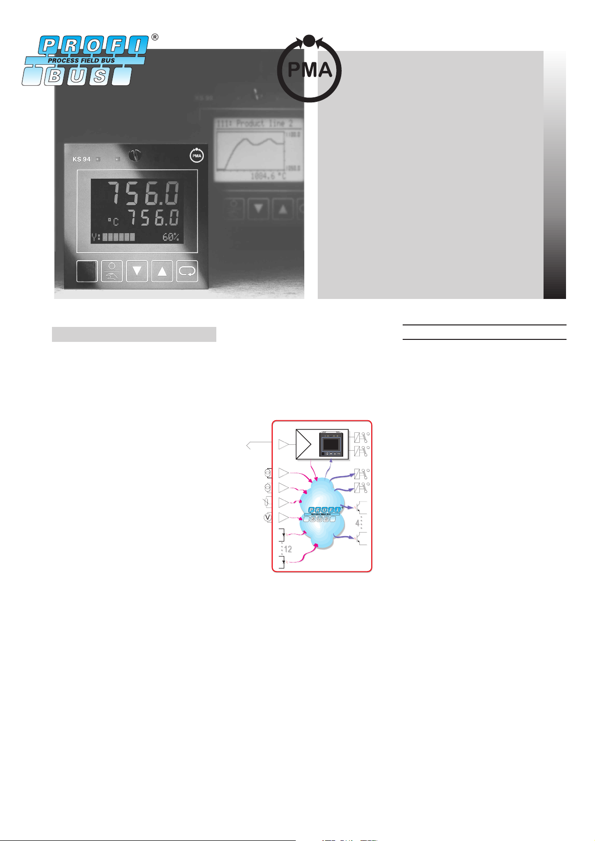
DESCRIPTION
The PROFIBUS-DP option enables the
KS 94 to be connected to PROFIBUS-DP
networks. This allows de-centralized and
independent industrial and process controllers to be integrated into PLC or PC
systems. The PLC/IPC transfers
set-points and control information to the
KS 94, and polls process values cyclically.
All control functions and the associated
scaling and monitoring tasks are executed independently. This ensures high
process safety together with short times
for engineering and commissioning.
DISPLAY AND OPERATION
Via its “day & night” display, the KS 94
shows all process data locally and easily
readable. If required, one line of the dis
play can be used to show a
freely-definable message.
Furthermore, the controller can be
switched to local operation, e.g. for com
missioning the control loop without any
previous programming of the PLC or the
supervisory system. In addition, the En
gineering Tool ET/KS 94 is available as a
useful device. It is connected via a
front-panel socket of the KS 94, and
serves for configuration, parameter set
ting, and operation of the controller.
DE-CENTRALIZED I/O
Apart from the control function of the
KS 94, it is possible to access all inputs
and outputs directly. In this way, all the
controller’s I/O are also available to the
PLC/IPC.
756.0
756.0
qm/h
y:ууууу 55
-
The basic functions of the KS 94 / DP,
such as inputs/outputs, control
functions, etc. are described in the data
sheet (9498 737 28213) for the KS 94.
-
-
Technical data
According to EN 50170 Vol. 2
Reading and writing of all process data,
parameters and configuration data.
DATA FORMAT
Real values such as set-points and process data are transmitted in the IEEE
format (REAL) or in the 16-bit fiexed
point format (FIX) with one digit behind
the decimal point (configurable).
PARAMETER CHANNEL
Process data and selected parameter
data are written and read cyclically. All
process-, parameter- and configuration
can be transmitted via parameter chan
nel. These data are transmitted over
several cycles on request.
-
The standard graphical trend display al
lows a qualitative evaluation of the
control results.
-
Page 2
CONFIGURABLE PROCESS DATA
MODULES
Module a (I/O):
process data
process value (xeff)
output value (yeff)
set-point (weff)
read
status
parameter channel
no
Module b (I/O + parameter channel):
process data
process value (xeff)
output value (yeff)
set-point (weff)
read
status
parameter channel
Module c (extended I/O + parameter):
process data
process value (xeff)
output value (yeff)
set-point (weff)
read
status
inputs (INP+di)
parameter channel
Module d (ext.. I/O + forcing +
parameter):
process data
process value (xeff)
output value (yeff)
set-point (weff)
read
status
inputs (INP+di)
parameter channel
Module e (variabel + para. channel):
process data
status word1+2
IN1...IN16
read
parameter channel
set-point (w)
output value (yman)
write
auto/manual
set-point (w)
output value (yman)
write
auto(manual
set-point (w)
output value (yman)
write
auto(manual
outputs (OUT+do)
set-point (w)
output value (yman)
write
auto(manual
inputs (INP+di)
control word 1+2
OUT1...OUT16
write
Writing of inputs/outputs can be acti
vated individually for each input and
output.
DATA CONTENTS (MODULES
E,F,G)
Status words 1 and 2
Reading the digital inputs
·
Sensor break/short-circuit status
·
Error and status information
·
Alarms and controller outputs
·
Automatic or manual operation
·
Control words 1 and 2
Automatic/Manual switch-over
·
Controller off/Set-point switch-over
·
Forcing of digital inputs
·
Forcing/enabling of digital outputs
·
Local/Remote switch-over
·
Inputs IN1...IN16
The data to be read from the KS 94 can
be defined by means of the Engineering
Tool ET/KS 94 (Version 4.0 upwards).
It is possible to access all signals and pa
rameters (ð Fig.4).
Outputs OUT1...OUT16
The data to be transmitted to the KS 94
can be defined by means of the Engineering Tool ET/KS 94 (Version 4.0
upwards). It is possible to access all signals and parameters (ð Fig.4).
FUNCTIONS
Enabling the controller outputs
The control word allows you to en
able/disable the digital controller outputs.
-
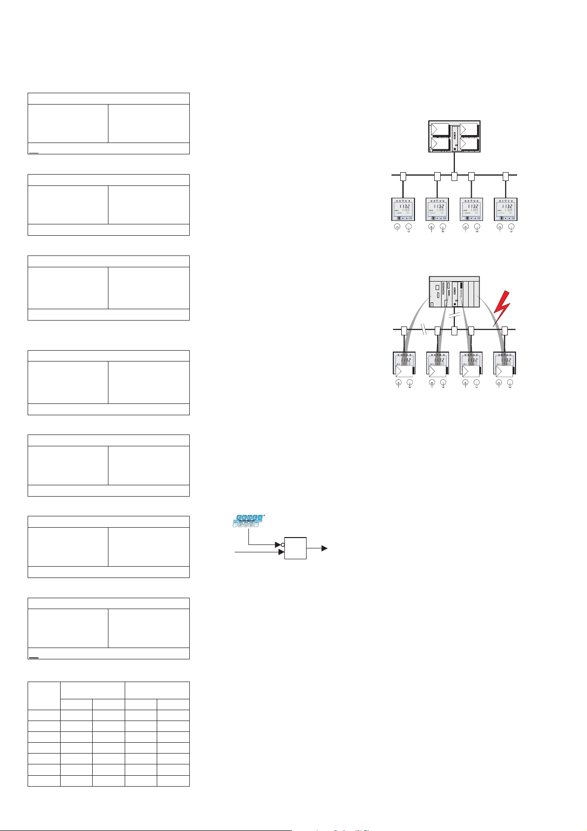
Back-up controller mode
During “normal” operation, the control
output is computed by the master. The
KS 94 is used to measure the process
values, to generate the control output
signal, and for display.
If the master or the bus communication
should fail, the KS 94 takes over auto
matically and bumplessly.
-
CONNECTION
AMP flat-pin terminals 1 x 6,3 mm or
2 x 2,8 mm.
By needs of an adapter (ðAccessories)
Sub-D connectors or screw terminals
can be used.
-
Module f (variabel + para. channel):
process data
status word1+2
IN1...IN6
read
parameter channel
control word 1+2
OUT1...OUT6
write
Module g (multiplex transmission):
process data
status word1+2
Index IN (1...16)
read
IN
no
parameter channel
control word 1+2
Index OUT (1...16)
write
OUT
Memory requirements (byte):
Module read write
FIX REAL FIX REAL
a 814610
b 16221418
c 30462028
d 30462640
e 44764476
f 24362436
g 810810
controller
&
digital output
(do, OUT)
De-centralized I/O
All inputs and outputs of the KS 94 are
directly accessible via the I/O memory
area. In this way it is possible to make
use of additional input/output functions
apart from the control function. Analog
values are transmitted in the scaled for
-
mat.
Input forcing
All physical inputs can be overwritten via
the PROFIBUS-DP. In this way it is pos
sible e.g. to define individual elements of
a multi-element control loop via the bus,
or to let the PLC compute corrections for
process value/set-point.
2 KS 94 PROFIBUS
Page 3

DIAGNOSIS/BEHAVIOR ON ERROR
If the master fails or the bus connection
is interupted (communication error) the
last setpoint remains active and the
KS 94 works independently. If the mas
ter PLC is switched in stop-mode the
Clear Data Signal will be suppressed and
the last setpoint remains active, too! In
case of a fault on the bus, the KS 94 can
activate an alarm relay.
Plain-text display on the controller front:
Master missing
·
Parameter error
·
Configuration error
·
Loss of master
·
CABLE
According to EN 50170 Vol. 2
TRANSMISSION SPEEDS AND
CABLE LENGTHS
Automatic transmission speed detection
Speed Max. cable length
9,6 kbit/s 1200 m
31,25 kbit/s 1200 m
45,45 kbit/s 1200 m
187,5 kbit/s 1200 m
500 kbit/s 400 m
1,5 Mbit/s 200 m
3 Mbit/s * 100 m
6 MBit/s * 100 m
12 Mbit/s * 100 m
*
Sub-D adapter 9407-998- 00031 required!
Fig. 1 Connection diagram KS 94/DP:
90...250V
-
24VUC
OUT2
-
.
24 V
+
+
di8( )
+
di9( )
+
di 10 ( )
+
di 11 ( )
+
di 12 ( )
Option C
do 5
do 6
GND
+
}
_
+
}
_
+
_
galvanic isolation
C
oder
or
24 V
-
di1( )
+
di2( )
+
+ Volt
+mA
_
Volt/mA
-
24 V
+
+
di 3 ( )
+
di 4 ( )
+
di 5 ( )
+
di 6 ( )
+
di 7 ( )
do 1
do 2
do 3
do 4
VP (5V)
GND
RxD/TxD-N
RxD/TxD-P
Option B
Adapter
PROFIBUS-DP
ADDRESSES
0...126 (factory setting: 126)
Remote setting of address allowed
OTHER FUNCTIONS
Sync and Freeze
TERMINATING RESISTORS
Internally selectable with wire-hook
switches
Required Accessories
ENGINEERING SET
Content:
·
GSD-file
·
Manual, data description
·
Function blocks for Step5, Step7 used
for reading and writing of parameter
and configuration data via parameter
channel.
Universal S5 Function Block for
Parameter Channel
By needs of this FB the parameter chan
nel can be used in P- and Q-tiles,
extended P-area and together with the
special function block FB IM380C.
Fig. 2 Sub-D adapter:
Fig. 4 Selection of data content by means of the Engineering Tool (process data module e, f, g):
Fig. 3 Dimensions (in mm):
96 105
160
8.8.8.8
96
M3/h
8.8.8.8
Y:ыыыыыо 55%
96
min. 0 C
60 Cmax.
-
1...16
92
max.
95% rel.
+0,8
%
+0,8
92
KS 94 PROFIBUS 3
Page 4

g
ORDERING INFORMATIONS
940
Flat pin connectors
Screw terminal connectors
9
7
8
KS 94 2
KS 94 with transmitter power supply 3
90...250V AC 4 relays
90...250V AC 3 relays + current output
3
4
24VUC4relays 7
24V UC 3 relays + current output 8
no interface 0
TTL-interface + di/do 1
RS422+di/do+clock
PROFIBUS-DP + di/do
IB+di/do
NTER US
2
3
4
no extension 0
INP3, INP4, OUT3, di/do 1
OUT3 5
no additional functions 0
measurement correction 1
measurement correction + programmer 2
Standard configuration 0
2-point controller
3-point controller
continuous controller
3-point controller (Logic/relays) 4
3-point stepping controller for 3-element control 5
continuous controller for 3-element control 6
uration to specification 9
confi
1
1
2
3
Accessory Equipement Order no..
Engineering Set German 9407-999-05201
Engineering Set Englisch 9407-999-05101
Adapter, screw terminals (max. 1,5Mbit/s) 9407-998-00021
Adapter, Sub-D 9407-998-00031
Universal S5 function block for parameter channel 9407-999-05301
Germany
PMA
Prozeß- und Maschinen-Automation GmbH
Miramstraße 87, D-34123 Kassel
Tel.: +49 561 505 - 1403
Fax: +49 561 505 - 1661
E-mail: export@pma-online.de
Internet: http://www.pma-online.de
Printed in Germany - Edition 0306 Data subject to alteration without notice 9498-737-37213
Your local distributor
 Loading...