

Page 1
KS10-I
Operating Instructions
Bedienungsanleitung
KS 10-I
9499 040 61241
Valid from / Gültig ab: 8378
Page 2

CONTENT
Page
Mini Jumper and DIP Switch 3
Keys and Displays 4
Menu Overview 5
Parameter Description 6
Installation 13
Wiring Precautions 14
Error Codes 15
INHALT
Seite
Steckbrücken und DIP-Schalter 17
Anzeige- und Bedienelemente 18
Menü Übersicht 19
Parameterbeschreibung 20
Installation 27
Verdrahtungshinweise 28
Fehler-Codes 29
Symbols used on the device
à EU- Conformity mark
a Attention please follow
the operating instructions!
Symbole auf dem Gerät
à EU-Konformitätskennzeichnung
a Achtung, bitte Bedienungsanleitung beachten!
All rights reserved. No part of this documentation may be
reproduced or published in any form or by any means
without prior written permission from the copyright owner
.
A publication of :
PMA
Prozeß- und Maschinen-Automation GmbH
P.O.Box 310 229 · D-34058 Kassel · Germany
Alle Rechte vorbehalten. Ohne vorhergehende schriftliche
Genehmigung ist der Nachdruck, auch die auszugsweise
fotomechanische oder anderweitige Wiedergabe, dieses Dokumentes
nicht gestattet.
Dies ist eine Dokumentation von:
PMA
Prozeß- und Maschinen-Automation GmbH
P.O.Box 310 229 · D-34058 Kassel · Germany
Page 3
9499 040 61241 2
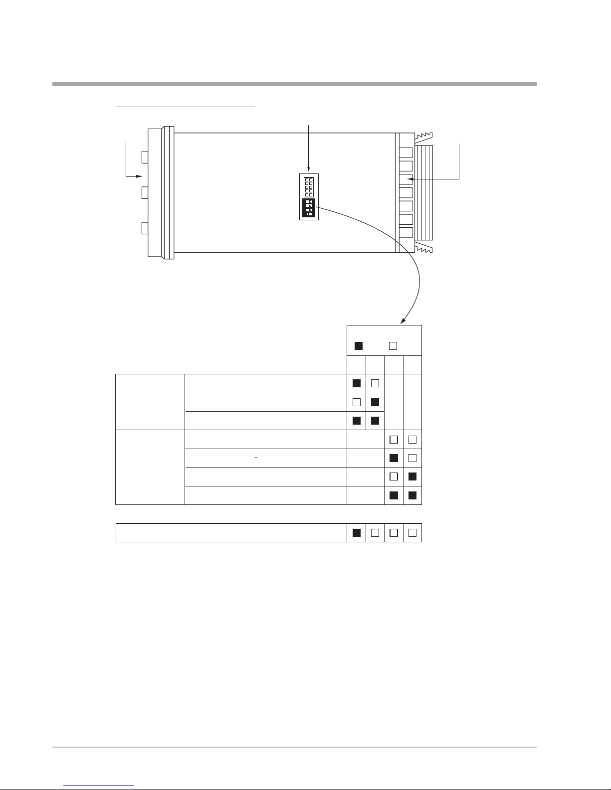
Mini Jumper and DIP Switch
Front
Panel
Rear
Terminal
Access Hole
Controller chassisview below
1
ONDIP
234
When the unit leaves the factory, the DIP switch is set so that TC & RTD are selected
for input 1 and all parameters are unlocked. Lockout function is used to disable the
adjustment of parameters as well as operation of calibration mode.
However the menu can still be viewed even if under lockout condition.
SEL1- SEL5 represent those parameters which are selected by using SEL1, SEL2,...
SEL5 parameters contained in Setup menu. The selected parameters are then
allocated at the beginning of the user menu.
*
TC, RTD, mV
0-1V, 0-5V, 1-5V, 0-10V
0-20 mA, 4-20 mA
Input 1
Select
All parameters are Unlocked
Only SP1, SEL1 SEL5 are unlocked
Only SP1 is unlocked
All Parameters are locked
Lockout
12
34
DIP Switch
:ON :OFF
Factory Default Setting
*
Operating Instructions KS10-I
Page 4
3 9499 040 61241
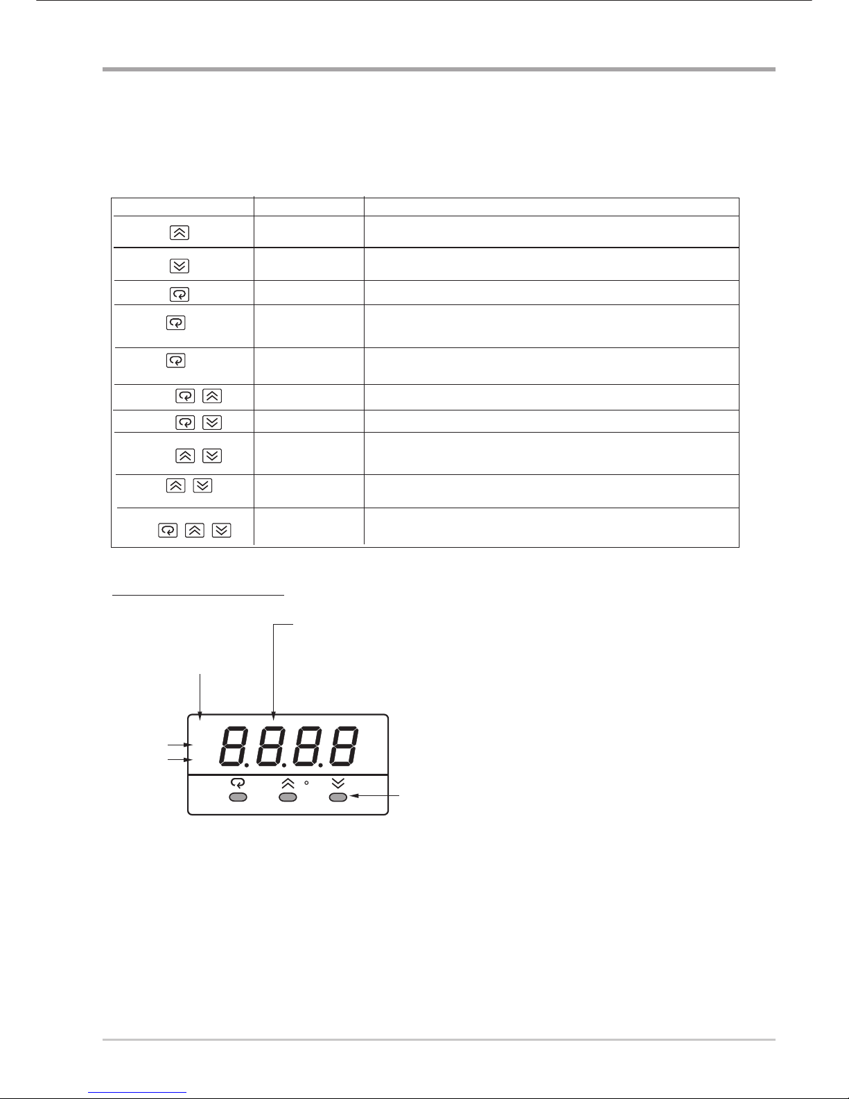
Keys and Displays
Keypad Operation
The unit is programmed by using three keys on the front panel.
The available key functions are listed as following table.
Press and release quickly to increase the value of the displayed parameter.
Press and hold to accelerate increment speed.
Press and release quickly to decrease the value of the displayed parameter.
Press and hold to accelerate decrement speed.
Select the parameter in a direct sequence.
Allow access to more parameters in user menu, also used to Enter manual
mode, auto-tune mode, default setting mode and save calibration data
during calibration procedure.
Select the parameter in a reverse sequence during menu scrolling.
Select the operation Mode in sequence.
Reset the front panel display to a normal display mode, also used to leave
the specific Mode execution and ending the auto-tune and manual control
execution, and quit the sleep mode.
The controller enters the sleep mode if the sleep function ( SLEP ) is enabled
( select YES ).
By entering correct security code to allow execution of engineering programs.
This function is used only in the factory to manage the diagnostic reports.
The user should never attempt to operate this function.
Press
for at least 3 seconds
Press
for at least 6 seconds
Press
Press
Press
Press
Press
for at least 3 seconds
Up Key
Down Key
Scroll Key
Enter Key
Start Record Key
Reverse Scroll Key
Mode Key
Reset Key
Sleep Key
Factory Key
TOUCHKEYS FUNCTION DESCRIPTION
Reset historical values of PVHI and PVLO and start to record the peak
process value.
Front Panel Description
O1
O2
A1
C
Alarm 1
Indicator
Output 2
Indicator
3 Silicone Rubber Buttons
for ease of control setup
and set point adjustment.
Output 1
Indicator
4-digit Display
to display process value,
set point value, menu symbol,
parameter value, control output
value and error code etc.
KS10-I economy
PMA
Page 5

9499 040 61241 4
Menu Overview
PV Value
SV Value
User
Menu
Setup
Menu
Hand (Manual)
Control
Mode
Auto-tuning
Mode
Display
Mode
Apply these modes will break the
control loop and change some of the
previous setting data. Make sure that if
the system is allowable to use these
modes.
A changing of Calibrationdata is to be
RAMP
A2DV
A2SP
A1DV
A1SP
TIME
PB1
SHIF
CPB
REFC
TD1
OFST
TI1
TD2
TI2
PB2
SP2
PL2
PL1
A2HY
A1HY
O1HY
SEL1
SEL5
SEL4
SEL3
SEL2
PVHI
PVLO
PV1
PV2
PB
TD
TI
DV
CJCT
PVR
PVRH
PVRL
H
C
AOHI
IN1L
SP1H
SP2F
AOLO
DP1
SP1L
AOFN
IN1U
SPMD
STOP
IN1
IN1H
IN2H
SLEP
PARI
IN2L
SELF
FILT
PVMD
EIFN
DATA
DP2
BAUD
IN2U
ADDR
IN2
PROT
COMM
FUNC
O1TY
O2TY
A1MD
A2FT
OUT1
OUT2
A1FN
A2MD
O1FT
O2FT
A2FN
CYC1
CYC2
A1FT
SEL1
DISF
SEL2
SEL5
SEL4
SEL3
H
C
V2G
MA1G
SR1
REF1
CJG
CJTL
V1G
ADG
AD0
Calibration
Mode
for 3 seconds
for 3
seconds
Default
Setting
Mode
FILE
To execute the
default setting
program
for
3 seconds
Press for 3 seconds to enter
the auto-tuning mode
The flow chart shows a complete listing of all parameters.
For actual application the number of available parameters
depends on setup conditions, and should be less
than that shown in the flow chart. See Appendix (Manual)
for the existence conditions of each parameter.
*1:
You can select at most 5 parameters put in front of the user
menu by using SEL1 to SEL5 contained at the bottom of
setup menu.
Set DISF (display format) value in the setup menu to
determine whetherPV or SVis displayed.
*2:
*3:
*1
*1
*3
or
*2
Display Go Home
The menu will revert to
PV/SV display after keyboard
is kept untouched for
2 minutes except Display
Mode Menu and Manual
Mode Menu. However, the
menu can revert to PV / SV
display at any time by
pressing and .
Page 6
5 9499 040 61241
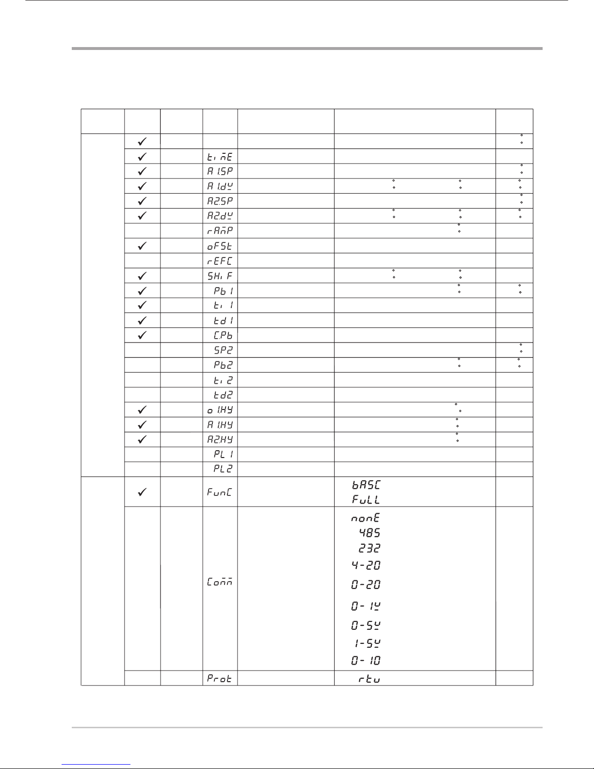
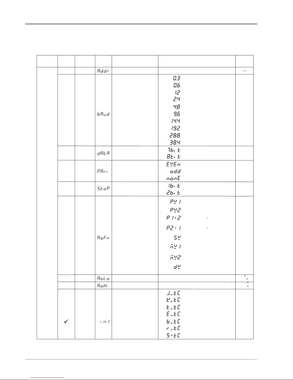
Parameter Description
Parameter Description
Parameter
Description
Range
Default
Value
Contained
in
Basic
Function
Parameter
Notation
Display
Format
SP1
Set point 1
SP1L SP1H
100.0 C
(212.0 F)
TIME
0 6553.5 minutes 0.0
Dwell Time
A1SP
100.0 C
(212.0 F)
Alarm 1 Set point
A1DV
Alarm 1 Deviation Value
-200.0 C
(-360.0 F)
10.0 C
(18.0 F)
A2SP
Alarm 2 Set point
100.0 C
(212.0 F)
A2DV
Alarm 2 Deviation Value
-200.0 C
(-360.0 F)
10.0 C
(18.0 F)
RAMP
Ramp Rate
0 0.0
OFST
REFC
SHIF
PB1
TI1User
Menu
Setup
Menu
TD1
Offset Value for P control
PV1 Shift (offset) Value
Proportional Band 1 Value
Integral Time 1 Value
Derivative Time 1 Value
0
0
0
0
0
25.0
100
CPB
Cooling Proportional Band
Value
1
100
25.0
-200.0 C
(-360.0 F)
10.0 C
(18.0 F)
0.0
Reference Constant for
Specific Function
2
Low:
Low:
Low:
Low:
Low:
Low:
Low:
Low:
Low:
Low:
Low:
Low:
Low:
Low:
Low:
Low:
Low:
Low:
High:
High:
Low:
200.0 C
( 360.0 F)
500.0 C
(900.0 F)
100.0 %
60
200.0 C
( 360.0 F)
High:
High:
High:
High:
High:
SP2
PB2
TI2
TD2
O1HY
A1HY
A2HY
PL1
PL2
COMM
PROT
Set point 2
Proportional Band 2 Value
Integral Time 2 Value
Derivative Time 2 Value
Output 1 ON-OFF Control
Hysteresis
Hysteresis Control of Alarm 1
Hysteresis Control of Alarm 2
Output 1 Power Limit
Output 2 Power Limit
Function Complexity Level
Communication Interface
Type
COMM Protocol Selection
0
Low:
0
0
0
0.1
0.1
0.1
0
100
100
100
25.0
37.8 C
(100.0 F)
1000 sec
360.0 sec
255 %
500.0 C
(900.0 F)
200.0 C
( 360.0 F)
High:
High:
High:
High:
High:
High:
1000 sec
500.0 C
(900.0 F)
High:
High:
High:
High:
High:
High:
High:
100 %
100 %
360.0 sec
55.6 C
( 100.0 F)
10.0 C
(18.0 F)
10.0 C
(18.0 F)
10.0 C
(18.0 F)
0.1
0.1
0.1
FUNC
0
Basic Function Mode
:
Full Function Mode
:
1
0
:
No communication function
:
1
RS-485 interface
2
:
RS-232 interface
:
3
4 - 20 mA analog retransmission
output
4
:
0 - 20 mA analog retransmission
output
:
5
0 - 1V analog retransmission
output
6
:
0 - 5V analog retransmission
output
:
7
1 - 5V analog retransmission
output
8
:
:
0 - 10V analog retransmission
output
1
1
0
See Table 1.5, 1.6
See Table 1.5, 1.7
See Table 1.5, 1.8
0
Modbus protocol RTU mode
Page 7
9499 040 61241 6
Parameter Description continued/2
Parameter
Description
Range
Default
Value
Contained
in
Basic
Function
Parameter
Notation
Display
Format
:
:
:
:
:
:
:
:
:
:
:
BAUD
DATA
PARI
STOP
AOFN
Baud Rate of Digital COMM
Data Bit count of Digital
COMM
Parity Bit of Digital COMM
Stop Bit Count of Digital
COMM
Analog Output Function
5
1
0
0
0
1
(0)
AOLO
AOHI
Analog Output Low Scale
Value
Analog Output High Scale
Value
-19999
-19999
45536
45536
ADDR
Address Assignment of Digital
COMM
Low:
Low:
Low:
High:
High:
High:
1
255
0
0
1
1
2
2
3
3
4
4
5
5
6
6
7
8
9
0.3 Kbits/s baud rate
0.6 Kbits/s baud rate
1.2 Kbits/s baud rate
2.4 Kbits/s baud rate
4.8 Kbits/s baud rate
9.6 Kbits/s baud rate
14.4 Kbits/s baud rate
19.2 Kbits/s baud rate
28.8 Kbits/s baud rate
38.4 Kbits/s baud rate
0
7 data bits
:
:
:
:
:
:
:
:
:
:
:
:
:
1 8 data bits
0
1
0
2
1
Even parity
Odd parity
No parity bit
One stop bit
Two stop bits
0
:
Retransmit IN1 process value
1
:
Retransmit IN2 process value
4
:
Retransmit set point value
5
:
Retransmit output 1 manipulation
value
6
:
Retransmit output 2 manipulation
value
2
:
Retransmit IN1 IN2 difference
process value
3
:
Retransmit IN2 IN1 difference
process value
7
:
Retransmit deviation(PV-SV)
Value
0C
(32.0 F)
100.0 C
(212.0 F)
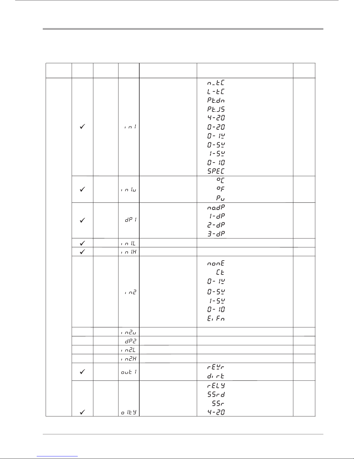
IN1
IN1 Sensor Type Selection
T type thermocouple
E type thermocouple
B type thermocouple
R type thermocouple
S type thermocouple
J type thermocouple
K type thermocouple
Parameter Description ( continued 2/7 )
Setup
Menu
Page 8
7 9499 040 61241
Parameter Description continued/3
Low:
Low:
High:
High:
IN2U
DP2
IN2L
IN2H
IN2 Unit Selection
IN2 Decimal Point Selection
IN2 Low Scale Value
IN2 High Scale Value
-19999
-19999
45536
45536
Same as IN1U
Same as DP1
0
1000
2
1
Parame ter
Des cription
Ra ng e
Default
Value
Contained
in
Bas ic
Func tion
Parame ter
No tatio n
Display
Fo rma t
IN1U
IN1
DP1
IN1L
IN1H
IN1 Unit Selection
IN1 Sensor Type Selection
IN1 Decimal Point Selection
IN1 Low Scale Value
IN1 High Scale Value
-19999
-19999
45536
45536
7
13
4
8
14
5
9
0
15
6
10
1
16
7
20
11
17
12
0
0
1
1
2
2
3
N type thermocouple
L type thermocouple
PT 100 ohms DIN curve
PT 100 ohms JIS curve
4 - 20 mA linear current input
0 - 20 mA linear current input
0 - 1V linear Voltage input
0 - 5V linear Voltage input
1 - 5V linear Voltage input
0 - 10V linear Voltage input
Special defined sensor curve
Low:
Low:
High:
High:
0
1000
1
0
(1)
1
(0)
IN2
IN2 Signal Type Selection
1
IN2 no function
Current transformer input
0 - 1V linear voltage input
0 - 5V linear voltage input
1 - 5V linear voltage input
0 - 10V linear voltage input
:
:
:
:
:
:
:
:
:
:
:
:
:
:
:
:
:
:
:
:
:
:
:
:
:
Degree C unit
Degree F unit
Process unit
No decimal point
1 decimal digit
2 decimal digits
3 decimal digits
Output 1 Function
0
0
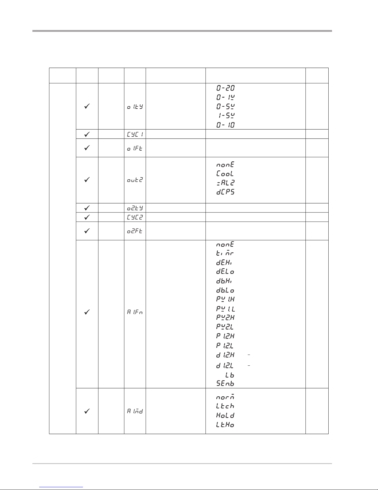
OUT1
O1TY
0
1
Reverse (heating ) control action
Direct (cooling) control action
:
:
0
1
2
3
Relay output
Solid state relay drive output
Solid state relay output
4 - 20 mA current module
:
:
:
:
Output 1 Signal Type
Parameter Description ( continued 3/7 )
Setup
Menu
Perform Event input function
Page 9
9499 040 61241 8
Parameter Description continued/4
Parame ter
Des cription
Ra ng e
Default
Va l u e
Contained
in
Bas ic
Func tion
Parame ter
No tatio n
Display
Fo rma t
4
5
6
7
0 - 20 mA current module
0 - 1V voltage module
0 - 5V voltage module
1 - 5V voltage module
8
0 - 10V voltage module
:
:
:
:
:
CYC1
O1TY
Output 1 Cycle Time
100.0 sec 18.0
0
0.1
Low:
High:
O1FT
Output 1 Failure Transfer
Mode
Select BPLS ( bumpless transfer ) or 0.0 ~ 100.0
% to continue output 1 control function as the unit
fails, power starts or manual mode starts.
Select BPLS ( bumpless transfer ) or 0.0 ~ 100.0
% to continue output 2 control function as the unit
fails, power starts or manual mode starts.
BPLS
Output 2 Function
OUT2
2
0
1
2
: PID cooling control
: Perform alarm 2 function
: Output 2 no function
3
: DC power supply module
installed
O2TY
CYC2
O2FT
Output 2 Signal Type
Output 2 Cycle Time
Output 2 Failure Transfer
Mode
100.0 sec
BPLS
18.0
0
0.1
Same as O1TY
Low:
High:
A1FN
Alarm 1 Function
2
6
IN1 process value high alarm
:
9
IN2 process value low alarm
:
0
No alarm function
:
4
Deviation band out of band alarm
:
1
Dwell timer action
:
5
Deviation band in band alarm
:
8 IN2 process value high alarm
:
3
Deviation low alarm
:
2
Deviation high alarm
:
11
IN1 or IN2 process value low
alarm
:
7 IN1 process value low alarm
:
10
IN1 or IN2 process value high
alarm
:
12
IN1 IN2 difference process value
high alarm
:
13
IN1 IN2 difference process value
low alarm
:
:
:
14 Loop break alarm
15 Sensor break or A-D fails
:
:
:
:
1
2
3
0
Normal alarm action
Latching alarm action
Hold alarm action
Latching & actionHold
A1MD
Alarm 1 Operation Mode
0
Parameter Description ( continued 4/7 )
Setup
Menu
Output 1 Signal Type
Page 10

9 9499 040 61241
Parameter Description continued/5
Parameter
Description
Range
Default
Value
Contained
in
Basic
Function
Parameter
Notation
Display
Format
:
:
SELF
Self Tuning Function
Selection
:
:
0
1
Self tune function disabled
Self tune function enabled
SLEP
Sleep mode Function
Selection
0
Sleep mode function disabled
Sleep mode function enabled
1
0
0
:
:
A1FT
A2FT
A2FN
Alarm 1 Failure Transfer
Mode
Alarm 2 Failure Transfer
Mode
Alarm 2 Function
1
2
0
1
Alarm output OFF as unit fails
Alarm output ON as unit fails
Same as A1FN
Same as A1MD
Same as A1FT
A2MD
Alarm 2 Operation Mode
0
1
1
EIFN
Event Input Function
3
4
SP2, PB2, TI2, TD2 activated to
replace SP1, PB1, TI1, TD1
Reset alarm 1 output
9
10
Disable Output 1 & Output 2
Lock All Parameters
0
Event input no function
:
1 SP2 activated to replace SP1
:
2
PB2, TI2, TD2 activated to replace
PB1, TI1, TD1
:
:
:
5
Reset alarm 2 output
:
6
Resetalarm1&alarm 2
:
7
Disable Output 1
:
8
Disable Output 2
:
:
:
PVMD
PV Mode Selection
:
:
0
1
Use PV1 as process value
Use PV2 as process value
:
2
Use PV1 PV2 (difference) as
process value
:
3
Use PV2 PV1 (difference) as
process value
0
0
1
2
3
4
0 second time constant
0.2 second time constant
0.5 second time constant
1 second time constant
2 seconds time constant
5 seconds time constant
10 seconds time constant
20 seconds time constant
30 seconds time constant
60 seconds time constant
5
6
7
8
9
:
:
:
:
:
:
:
:
:
:
FILT
Filter Damping Time
Constant of PV
2
Parameter Description ( continued 5/7 )
Setup
Menu
Page 11

9499 040 61241 10
Parameter Description continued/6
:
:
SP2F
DISF
Format of set point 2 Value
Display Format
0
1
set point 2 (SP2) is an actual value
set point 2 (SP2) is a deviation
value
0
Parame ter
Des cription
Ra ng e
Default
Va l u e
Contained
in
Bas ic
Func tion
Parame ter
No tatio n
Display
Fo rm at
:
:
:
:
:
:
SPMD Set point Mode Selection
0
1
2
3
4
5
Use SP1 or SP2 (depends on EIFN)
as set point
Use minute ramp rate as set point
Use hour ramp rate as set point
Use IN1 process value as set point
Use IN2 process value as set point
Selected for pump control
SEL1 Select 1'st Parameter
0
:
:
:
:
:
:
:
:
:
:
:
:
:
:
:
:
:
:
:
:
16
17
18
Parameter PB2 put ahead
Parameter TI2 put ahead
Parameter TD2 put ahead
0
0
1
1
2
3
4
5
6
No parameter put ahead
Display PV value
Display SV value
Parameter TIME put ahead
Parameter A1SP put ahead
Parameter A1DV put ahead
Parameter A2SP put ahead
Parameter A2DV put ahead
Parameter RAMP put ahead
Parameter OFST put ahead
Parameter REFC put ahead
Parameter SHIF put ahead
Parameter PB1 put ahead
Parameter TI1 put ahead
Parameter TD1 put ahead
Parameter CPB put ahead
Parameter SP2 put ahead
7
8
9
10
11
12
13
14
15
Reserved, not used
0
SEL2
SEL3
SEL4
Same as SEL1
Same as SEL1
Same as SEL1
0
0
0
Low:
Low:
High:
High:
SP1L
SP1H
SP1 Low Scale Value
SP1 High Scale Value
-19999
-19999
45536
45536
0C
(32.0 F)LL
1000.0 C
(1832.0 F)LL
Parameter Description ( continued 6/7 )
Select 2'nd Parameter
Select 3'rd Parameter
Select 4'th Parameter
Select 5'th Parameter
SEL5
Same as SEL1
0
AD0
ADG
V1G
A to D Zero Calibration
Coefficient
A to D Gain Calibration
Coefficient
Voltage Input 1 Gain
Calibration Coefficient
-360 360
-199.9 199.9
-199.9 199.9
Low:
Low:
Low:
High:
High:
High:
Low:
High:
CJTL
Cold Junction Low
Temperature Calibration
Coefficient
-5.00 CB 40.00 CL
Calibration
Mode
Menu
Setup
Menu
Page 12

11 9499 040 61241
Parameter Description continued/7
Parameter
Description
Range
Default
Value
Contained
in
Basic
Function
Parameter
Notation
Display
Format
Low:
High:
V2G
Voltage Input 2 Gain
Calibration Coefficient
-199.9 199.9
Low:
Low:
Low:
Low:
High:
High:
High:
High:
CJG
REF1
SR1
MA1G
Cold Junction Gain
Calibration Coefficient
Reference Voltage 1
Calibration Coefficient for
RTD 1
Serial Resistance 1
Calibration Coefficient for
RTD 1
mA Input 1 Gain Calibration
Coefficient
-199.9
-199.9
-199.9
-199.9
199.9
199.9
199.9
199.9
Parameter Description ( continued 7/7 )
Calibration
Mode
Menu
Display
Mode
Menu
Low:
Low:
High:
High:
PVHI
PVLO
Historical Maximum Value of
PV
Historical Minimum Value of
PV
-19999
-19999
45536
45536
Low:
Low:
High:
High:
MV1
MV2
Current Output 1 Value
Current Output 2 Value
0
0
100.00 %
100.00 %
Low:
Low:
Low:
Low:
Low:
Low:
Low:
Low:
Low:
Low:
High:
High:
High:
High:
High:
High:
High:
High:
High:
High:
DV
PV1
PV2
PB
TI
TD
CJCT
PVR
PVRH
PVRL
-12600
-19999
-19999
12600
45536
45536
0
0
Current Deviation (PV-SV)
Value
IN1 Process Value
IN2 Process Value
Current Proportional Band
Value
Current Integral Time Value
Current Derivative Time
Value
Cold Junction Compensation
Temperature
Current Process Rate Value
Maximum Process Rate Value
Minimum Process Rate Value
0
4000 sec
1440 sec
500.0 C
(900.0 F)LL
-40.00 CL
-16383
-16383
-16383
90.00 CL
16383
16383
16383
Page 13

9499 040 61241 12
Installation
Unpacking
Mounting
Upon receipt of the shipment remove the unit from the carton and inspect the
unit for shipping damage.
If any damage due to transit , report and claim with the carrier.
Write down the model number, serial number, and date code for future reference
when corresponding with our service center. The serial number (S/N) and date
code (D/C) are labeled on the box and the housing of control.
Make panel cutout to dimension shown in the Figure below.
Take both mounting clamps away and insert the controller into panel cutout.
Install the mounting clamps back. Gently tighten the screws in the clamp till the
controller front panels is fitted snugly in the cutout.
Mounting Dimensions
Dangerous voltages capable of causing death are sometimes present
in this instrument. Before installation or beginning any troubleshooting
procedures the power to all equipment must be switched off and isolated. Units
suspected of being faulty must be disconnected and removed to a properly
equipped workshop for testing and repair. Component replacement and internal
adjustments must be made by a qualified maintenance person only.
To minimize the possibility of fire or shock hazards, do not expose this instrument
to rain or excessive moisture.
Do not use this instrument in areas under hazardous conditions such as excessive
shock, vibration, dirt, moisture, corrosive gases or oil. The ambient temperature of
the areas should not exceed the maximum rating specified.
98.0mm
Panel
10.0mm
12.5mm
SCREW
MOUNTING
CLAMP
22.2
+0.3
45
+0.5
_
0
_
0
Page 14

13 9499 040 61241
Wiring Precautions
w
w
w
w
w
w
w
w
w
w
Before wiring, verify the label for correct model number and options. Switch
off the power while checking.
Care must be taken to ensure that maximum voltage rating specified on the
label are not exceeded.
It is recommended that power of these units to be protected by fuses or circuit
breakers rated at the minimum value possible.
All units should be installed inside a suitably grounded metal enclosure to
prevent live parts being accessible from human hands and metal tools.
All wiring must conform to appropriate standards of good practice and local
codes and regulations. Wiring must be suitable for voltage, current, and
temperature rating of the system.
The " stripped " leads as specified in the Figure below are used for power and
sensor connections.
Beware not to over-tighten the terminal screws.
Unused control terminals should not be used as jumper points as they may
be internally connected, causing damage to the unit.
Verify that the ratings of the output devices and the inputs as specified in
Chapter 8 are not exceeded.
Electric power in industrial environments contains a certain amount of noise in
the form of transient voltage and spikes. This electrical noise can enter and
adversely affect the operation of microprocessor-based controls. For this
reason we strongly recommend the use of shielded thermocouple extension
wire which connects the sensor to the controller. This wire is a twisted-pair
construction with foil wrap and drain wire. The drain wire is to be attached to
ground at one end only.
4.5 7.0 mm
0.18" 0.27"
~
~
2.0mm
0.08" max.
Lead Termination
Connection Diagram
1234
5
6 7
891011
12 13 14
+
-
N
L
+
+
-
Measuring output
or
RS 485 Interface
Supply voltage
90-264 VAC
or
11-28 VUC
2 A / 240 VAC Relay
or
5V/30mALogic
or
0(4)-20 mA Continuous
or
0-10 V Continuous
Control output OUT1
ALM2
(OUT2)
OUT1
ALM1
Logic 5V / 100 mA
+
-
-
Universal input
INP 1
INP 2
-
+
mA / V
TX1 TX2
-
+
W/W2
or
or
Wext (V)
Current transformer
2 A/240 VAC
Page 15

9499 040 61241 14
Error Codes
Error Codes and Corrective Actions
Error
Code
Display
Symbol
Error Description
Corrective Action
Illegal setup values been used: PV1 is used for both PVMD
and SPMD. It is meaningless for control.
1
Check and correct setup values of PVMD and SPMD. PV
and SV can't use the same value for normal control
Illegal setup values been used: PV2 is used for both PVMD
and SPMD. It is meaningless for control
2
Same as error code 1
Illegal setup values been used: P1-2 or P2-1 is used for
PVMD while PV1 or PV2 is used for SPMD. Dependent
values used for PV and SV will create incorrect result
of control
3
Check and correct setup values of PVMD and SPMD.
Difference of PV1 and PV2 can't be used for PV while PV1
or PV2 is used for SV
Illegal setup values been used: Before COOL is used for
OUT2, DIRT ( cooling action ) has already been used for
OUT1, or PID mode is not used for OUT1 ( that is PB1 or
PB2=0,andTI1orTI2=0)
4
Illegal setup values been used: unequal IN1U and IN2U or
unequal DP1 and DP2 while P1-2 or P2-1 is used for PVMD
or, PV1 or PV2 is used for SPMD or, P1.2.H, P1.2.L, D1.2.H
or D1.2.L are used for A1FN or A2FN.
5
6
Check and correct setup values of IN1U, IN2U, DP1, DP2,
PVMD, SPMD, A1FN or A2FN. Same unit and decimal point
should be used if both PV1 and PV2 are used for PV, SV,
alarm 1 or alarm 2.
Illegal setup values been used: OUT2 select =AL2 but
A2FN select NONE
Check and correct setup values of OUT2 and A2FN. OUT2
will not perform alarm function if A2FN select NONE.
Illegal setup values been used: Dwell timer (TIMR) is
selected for both A1FN and A2FN.
7
Check and correct setup values of A1FN and A2FN. Dwell
timer can only be properly used for single alarm output.
Communication error: bad function code
10
Correct the communication software to meet the protocol
requirements.
Communication error: register address out of range
11
Don't issue an over-range address to the slave.register
Communication error: access a non-existent parameter
12
Don't issue a non-existent parameter to the slave.
Communication error: attempt to write a read-only data
14
Don't write a read-only data or a protected data to the slave.
Communication error: write a value which is out of range to
a register
15
Don't write an over-range data to the slave register.
26
Fail to perform auto-tuning function
2.Don't change set point value during auto-tuning
procedure.
3. Don't change Event input state during auto-tuning
procedure.
4.Use manual tuning instead of auto-tuning.
1.The PID values obtained after auto-tuning procedure are
out of range. Retry auto-tuning.
EEPROM can't be written correctly
29
Return to factory for repair.
Input2(IN2)sensor break, or input 2 current below 1 mA
if 4-20 mA is selected, or input 2 voltage below 0.25V if
1 - 5V is selected
38
Replace input 2 sensor.
Input1(IN1)sensor break, or input 1 current below 1 mA
if 4-20 mA is selected, or input 1 voltage below 0.25V if
1 - 5V is selected
39
Replace input 1 sensor.
40
A to D converter or related component(s) malfunction
Return to factory for repair.
Check and correct setup values of OUT2, PB1, PB2, TI1,
TI2 and OUT1. IF OUT2 is required for cooling control, the
control should use PID mode ( PB = 0, TI=0)andOUT1
should use reverse mode (heating action), otherwise, don't
use OUT2 for cooling control
Page 16

Page 17

9499 040 61241 16
Steckbrücken und DIP-Schalter
Konfiguration der DIP-Schalter
Thermoelement, Widerstandsthermometer, mV
0-1V, 0-5V, 1-5V, 0-10V
0-20 mA, 4-20 mA
Eingang1
Select
Alle Parameter freigegeben
NurSP1, SEL1 SEL5 freigegeben
Nur SP1 freigegeben
Alle Parameter gesperrt
Lockout
12
34
DIP Schalter
AN
AUS
Werkseinstellungen
Im Auslieferzustand ist der DIP-Schalter so eingestellt, daß Eingang 1 für Thermoelement und Widerstandsthermometer konfiguriert ist und alle Parameter freigegeben
sind. Mit der Funktion Lockout werden Parametereinstellung und Kalibrier-Mode
gesperrt.
Im Lockout-Zustand ist jedoch die Anzeige des Menüs möglich.
Die Parameter SEL1-SEL5 werden mit den Einstellmenüparametern SEL1, SEL2,
...SEL5 gewählt. Die Zuordnung der gewählten Parameter erfolgt am Anfang
des Bedienermenüs.
*
*
Front
Platte
Klemmen
Geräterückseite
Zugangsöffnung
Reglerunterseite
1
ON DIP
234
Bedienungsanleitung KS 10-I
Page 18

17 9499 040 61241
Bedienelemente und Anzeige
Ausgang 1
Ausgang 2
Alarmausgang 1
Bedientasten
Die Programmierung des Reglers erfolgt mit den drei Tasten auf der Reglerfront.
Die Tastenfunktionen sind in der folgenden Tabelle erläutert.
Zum Inkrementieren des Wertes des angezeigten Parameters Taste drücken und sofort wieder
loslassen. Zur Erhöhung der Inkrementierungsgeschwindigkeit Taste drücken und festhalten.
Zum Dekrementieren des Wertes des angezeigten Parameters Taste drücken und sofort
wieder loslassen. Zur Erhöhung der Dekrementierungsgeschwindigkeit Taste drücken und
festhalten.
Auswahl des Parameters in direkter Folge.
Zugriff zu weiteren Parametern des Bedienermenüs, Start der Betriebsarten Hand, Optimierung am Sollwert, Voreinstellung und Speicherung der Kalibrierdaten bei der Kalibrierung
Anwahl der Parameter in umgekehrter Folge beim Durchlaufen des Menüs.
Anwahl der Betriebsarten in Folge
Rücksetzen auf normalen Anzeigebetrieb, Ausstieg aus der angewählten Betriebsart und
Beenden der Optimierung am Sollwert und des Handbetriebes, Ausstieg aus der Betriebsart Sleep.
Bei freigegebener Sleep-Funktion (SLEP, JA wählen) geht der Regler in Betriebsart Sleep.
Eingabe des Passwortes zur Ausführung der Engineering-Programme. Diese Funktion ist
der Verwaltung der Diagnoseberichte während der Wartungsarbeiten vorbehalten. und
darf nicht vom Bediener benutzt werden.
mindestens
6 Sekunden drücken
mindestens
3 Sekunden drücken
und
und
und
drücken
drücken
drücken
und
und
mindestens
3 Sekunden drücken
Wert vergrößern
Wert verkleinern
Direkte Anwahl
Eingabe
Aufnahmestart
umgekehrte Anwahl
Betriebsmodus
Zurücksetzen
Schlafmodus
Service
TASTEN
FUNKTION BESCHREIBUNG
Rücksetzen der historischen Werte PVHI und PVLO und Start der Aufzeichnung für Spitzenwert.
Beschreibung der Frontansicht
KS10-Ieconomy
O1
O2
A1
C
PMA
3 Silicongummitasten für
die einfache Einstellung
der Regelparameter und
des Sollwertes
Anzeige für Istwert, Sollwert,
Menüsymbol,Parameterwerte,
Stellgröße, Fehlercode, usw.
Page 19

9499 040 61241 18
Menü Übersicht
Istwert
Sollwert
Bedienmenü
Einstellmenü
Handbetrieb
Optimierung
am Sollwert
Anzeigebetrieb
Voreinstellbetrieb
Kalibrierbetrieb
Achtung: Wenn diese Betriebsarten zugelassen
sind, wird der Regelkreis beim Start dieser
Betriebsarten unterbrochen, und die vorherigen
Einstelldaten werden geändert.
Eine Änderung der Kalibrierdaten ist unbedingt
zu vermeiden!
RAMP
A2DV
A2SP
A1DV
A1SP
TIME
PB1
SHIF
CPB
REFC
TD1
OFST
TI1
TD2
TI2
PB2
SP2
PL2
PL1
A2HY
A1HY
O1HY
SEL1
SEL5
SEL4
SEL3
SEL2
FILE
Zum Starten des
Voreinstellprogramms
PVHI
PVLO
PV1
PV2
PB
TD
TI
DV
CJCT
PVR
PVRH
PVRL
H
C
SEL1
AOHI
IN1L
SP1H
SP2F
DISF
AOLO
DP1
SP1L
AOFN
IN1U
SPMD
STOP
IN1
IN1H
IN2H
SLEP
PARI
IN2L
SELF
FILT
PVMD
EIFN
SEL2
DATA
DP2
BAUD
IN2U
ADDR
IN2
PROT
COMM
FUNC
O1TY
O2TY
A1MD
A2FT
OUT1
OUT2
A1FN
A2MD
O1FT
O2FT
A2FN
CYC1
CYC2
A1FT
SEL5
SEL4
SEL3
H
C
V2G
MA2G
MA1G
SR1
REF1
CJG
CJTL
V1G
ADG
AD0
3 Sekunden drücken
für 3
Sekunden
3 Sekunden
drücken
Zum Starten der Optimierung
am Sollwert, 3 Sekunden drücken
Das Ablaufdiagramm zeigt eine komplette Parameterliste.
In der Praxis ist die Anzahl der verfügbaren Parameter von
den Einstellbedingungen abhängig und sollte niedriger als
in dem obigen Ablaufdiagramm sein. Parameterbedingungen
siehe Tabelle 6.2 Menübedingungen.
*1:
Mit den Einstellparametern SEL1 bis SEL5 können max. 5
Parameter für das Bedienmenü festgelegt werden.
Der Parameter DISF im Einstellmenü legt fest ob der Ist- oder
der Sollwert angezeigt wird.
*2:
*3:
*1
*1
*2
*3
oder
Zurück zur Anzeige
des Ist-/Sollwerts
Außer im Anzeige- und
Handbetriebsmenü wird
mit diesem Menü wieder
der Istwert/Sollwert angezeigt, wenn für die Dauer
von 2 Minuten keine Taste
gedrückt wurde. Die Rückkehr zur Anzeige des Istwertes/Sollwertes ist ebenfalls jederzeit mit
und möglich.
Page 20

19 9499 040 61241
Parameterbeschreibung
Parameterbeschreibung
Parameter
beschreibung
Bereich
Voreinstellwert
enthalten
in
Grund-
funktion
Parameter
Bezeichnung
Anzeige
Form
SP1
Sollwert 1
SP1L SP1H
100.0 C
(212.0 F)
TIME
0 6553.5 minutes 0.0
Haltezeit
A1SP
100.0 C
(212.0 F)
Sollwert Alarm 1
A1DV
Regelabweichung Alarm 1
-200.0 C
(-360.0 F)
10.0 C
(18.0 F)
A2SP
Sollwert Alarm 2
100.0 C
(212.0 F)
A2DV
Regelabweichung Alarm 2
-200.0 C
(-360.0 F)
10.0 C
(18.0 F)
RAMP
Gradient Ramp
0 0.0
OFST
REFC
SHIF
PB1
TI1Bedien
menü
Einstellmenü
TD1
Offset für P-Regelung
Verschiebung Istwert
Proportionalbereich 1
Nachstellzeit 1
Vorhaltezeit 1
0
0
0
0
0
25.0
100
CPB
Proportionalbereich Kühlen
1
100
25.0
-200.0 C
(-360.0 F)
10.0 C
(18.0 F)
0.0
Referenzkonstante für
spezifische Funktion
2
tief
tief
tief
tief
tief
tief
tief
tief
tief
tief
tief
tief
tief
tief
tief
tief
tief
tief
tief
tief
hoch
hoch
hoch
hoch
hoch
hoch
hoch
hoch
hoch
hoch
hoch
hoch
hoch
hoch
hoch
hoch
hoch
hoch
hoch
hoch
200.0 C
( 360.0 F)
500.0 C
(900.0 F)
100.0 %
60
200.0 C
( 360.0 F)
SP2
PB2
TI2
TD2
O1HY
A1HY
A2HY
PL1
PL2
COMM
PROT
Sollwert2
Proportionalbereich 2
Nachstellzeit 2
Vorhaltezeit 2
Hysterese Ausgang 1
Zweipunktregelung
Hysterese Regelung Alarm 1
Hysterese Regelung Alarm 2
Spannungsgrenzwert
Ausgang 1
Spannungsgrenzwert
Ausgang 2
Funktionsumfang
Kommunikationsschnittstelle
Auswahl COMM-Protokoll
0
0
0
0
0.1
0.1
0.1
0
100
100
100
25.0
100.0 C
(212.0 F)
1000 sec
360.0 sec
255 %
500.0 C
(900.0 F)
200.0 C
( 360.0 F)
1000 sec
500.0 C
(900.0 F)
100 %
100 %
360.0 sec
55.6 C
( 100.0 F)
10.0 C
(18.0 F)
10.0 C
(18.0 F)
10.0 C
(18.0 F)
0.1
0.1
0.1
FUNC
0
Grundfunktionen
:
Erweiterter Funktionsumfang
:
1
0
:
keine Kommunikationsfunktion
:
1
RS-485 Schnittstelle
2
:
RS-232 Schnittstelle
:
3
4 - 20 mA Meßwertausgang
4
:
0 - 20 mA Meßwertausgang
:
5
0 - 1V Meßwertausgang
6
:
0 - 5V Meßwertausgang
:
7
1 - 5V Meßwertausgang
8
:
:
0 - 10V Meßwertausgang
1
1
0
Siehe Tabelle 1.5, 1.6
Siehe Tabelle 1.5, 1.7
Siehe Tabelle 1.5, 1.8
0
Betriebsart RTU Modbus-Protokoll
Page 21

9499 040 61241 20
Parameterbeschreibung (fortgesetzt/2)
Parameter
beschreibung
Bereich
Voreinstellung
Enthalten
in
Grund
Fuktion
Parameter
Bezeichnung
Anzeige-
form
:
:
:
:
:
:
:
:
:
:
:
BAUD
DATA
PARI
STOP
AOFN
Übertragungsgeschwindigkeit
Anzahl Datnbits
digitale Schnittstelle
Paritätsbit
digitale Schnittstelle
Anzahl Stop-Bit
digitale Schnittstelle
Analoge Ausgangsfunktion
5
1
0
0
0
1
(0)
AOLO
AOHI
Meßanfang Analogausgang
Meßende Analogausgang
-19999
-19999
45536
45536
ADDR
Digitale Schnittstellenadressierung
Low:
Low:
Low:
High:
High:
High:
1 255
0
0
1
1
2
2
3
3
4
4
5
5
6
6
7
8
9
0.3 Kbits/s baud rate
0.6 Kbits/s baud rate
1.2 Kbits/s baud rate
2.4 Kbits/s baud rate
4.8 Kbits/s baud rate
9.6 Kbits/s baud rate
14.4 Kbits/s baud rate
19.2 Kbits/s baud rate
28.8 Kbits/s baud rate
38.4 Kbits/s baud rate
0
7 Datenbit
:
:
:
:
:
:
:
:
:
:
:
:
:
1 8 Datenbit
0
1
0
2
1
gerade Parität
ungerade Parität
kein Paritätsbit
Ein Stop-Bit
Zwei Stop-Bits
0
:
Meßwertausgang Istwert IN1
1
:
Meßwertausgang Istwert IN 2
4
:
Meßwertausgang Sollwert
5
:
Meßwertausgang Stellgröße 1
6
:
Meßwertausgang Stellgröße 2
2
:
Meßwertausgang
Istwertdifferenz IN1-IN2
3
:
Meßwertausgang
Istwertdifferenz IN2-IN1
7
:
Meßwertausgang Regelabweichung
(Istwert-Sollwert)
0C
(32.0 F)
100.0 C
(212.0 F)
IN1
Auswahl Sensortyp IN1
Thermoelement Typ T
Thermoelement Typ E
Thermoelement Typ B
Thermoelement Typ R
Thermoelement Typ S
Thermoelement Typ J
Thermoelement Typ K
Einstellmenü
Page 22

21 9499 040 61241
Parameterbeschreibung (fortgesetzt/3)
Low:
Low:
High:
High:
IN2U
DP2
IN2L
IN2H
Auswahl Einheit IN2
Einstellung Dezimalpunkt IN2
Meßanfang IN2
Meßende IN2
-19999
-19999
45536
45536
Wie IN1U
Wie DP1
0
1000
2
1
Parameterbeschreibung
Bereich
Voreinstellung
Enthalten
in
Grund-
funktion
Parameterbezeichnung
Anzeige
IN1U
IN1
DP1
IN1L
IN1H
Auswahl Einheit IN1
Auswahl Sensortyp IN 1
Einstellung Dezimalpunkt IN 1
Meßanfang IN1
Meßende IN1
-19999
-19999
45536
45536
7
13
4
8
14
5
9
0
15
6
10
1
16
7
11
2
17
12
3
0
0
1
1
2
2
3
Thermoelement Typ N
Thermoelement Typ L
PT 100 Ohm DIN
PT 100 Ohm JIS
lineares Stromeingangssignal
4-20mA
lineares Stromeingangssignal
0-20mA
linearer Spannungseingang0-1V
linearer Spannungseingang 0 - 5V
linearer Spannungseingang 1 - 5V
linearer Spannungseingang 0 - 10V
Sensorcharakteristik nach Angabe
Low:
Low:
High:
High:
0
1000
1
0
(1)
1
(0)
IN2
Auswahl Eingangstyp IN1
1
IN2 keine Funktion
Eingang Stromwandler
lineares Stromeingangssignal
4-20mA
lineares Stromeingangssignal
0-20mA
linearer Spannungseingang0-1V
linearer Spannungseingang 0 - 5V
linearer Spannungseingang 1 - 5V
linearer Spannungseingang 0 - 10V
:
:
:
:
:
:
:
:
:
:
:
:
:
:
:
:
:
:
:
:
:
:
:
:
:
:
Einheit °C
Einheit °F
sonstige Einheit
kein Dezimalpunkt
1 Stelle hinter dem Komma
2 Stellen hinter dem Komma
3 Stellen hinter dem Komma
Funktion Ausgang 1
0
0
OUT1
O1TY
0
1
Ausgangsignal (Heizen) invers
Ausgangsignal (Kühlen) direkt
:
:
0
1
2
3
Relaisausgang
SSR-Ansteuerausgang
SSR-Ausgang
Stromausgang4-20mA
:
:
:
:
Signalart Ausgang 1
EinstellMenü
Page 23

9499 040 61241 22
Parameterbeschreibung (fortgesetzt/4)
Parameterbeschreibung
Bereich
Voreinstellung
Enthalten
in
Grund-
funktion
Parameterbezeichnung
Anzeigeform
4
5
6
7
Strommodul 0 - 20 mA
Spannungsmodul 0 - 1V
Spannungsmodul 0 - 5V
Spannungsmodul 1 - 5V
8
Spannungsmodul 0 - 10V
:
:
:
:
:
CYC1
O1TY
Zykluszeit Ausgang 1
100.0 sec 18.0
0
0.1
hoch
tief
O1FT
Umschaltung bei Fehler
Ausgang 1
Bei Fehler, Einschalten der Spannungsversorgung
bzw. Start, Handbetrieb zum Fortsetzen der Regelfunktion Ausgang 1 stoßfreie Umschaltung (BLPS)
bzw. 0,0...100,0% wählen
Bei Fehler, Einschalten der Spannungsversorgung
bzw. Start, Handbetrieb zum Fortsetzen der Regelfunktion Ausgang 2 stoßfreie Umschaltung (BLPS)
bzw. 0,0...100,0% wählen
BPLS
Funktion Ausgang 2
OUT2
2
0
1
2
: PID-Kühlen-Regelung
: Funktion Alarm 2
: Ausgang 2 keine Funktion
3
: Modul Gleichspannungs-
versorgung installiert
O2TY
CYC2
O2FT
Signaltyp Ausgang 2
Zykluszeit Ausgang 2
Umschaltung bei Fehler
Ausgang 2
100.0 %
BPLS
18.0
0
0.1
Wie O1TY
tief
hoch
A1FN
Funktion Alarm 1
2
6
Alarm High IstwertIN 1
:
9
Alarm Low Istwert IN 2
:
0
keine Alarmfunktion
:
4
Alarmabweichung
Abweichungsbereich
:
1
Zeitrelais
:
5
Alarmabweichung innerhalb
Bereich
:
8 Alarm High Istwert IN 2
:
3
Alarm Low Abweichung
:
2
Alarm High Abweichung
:
11
Alarm Low Istwert IN1 oder IN 2
:
7 Alarm Low Istwert IN 1
:
10
Alarm High Istwert IN 1 oder IN 2
:
12
Alarm High Istwertdifferenz IN1-IN 2
:
13
Alarm Low Istwertdifferenz IN1-IN2
:
14
15
Regelkreisalarm
Sensorbruch oder A-D Fehler
:
:
:
:
:
:
0
1
2
3
Normale Alarmfunktion
Alarmunterdrückung
Alarmhaltefunktion
Haltefunktion mit
Alarmunterdrückung
A1MD
Betriebsart Alarm 1
0
Einstellmenü
Signaltyp Ausgang 1
Page 24

23 9499 040 61241
Parameterbeschreibung (fortgesetzt/5)
Parameterbeschreibung
Bereich
Voreinstellung
Enthalten
in
Grund-
funktion
Parameterbezeichnung
Anzeige
:
:
:
:
SELF Auswahl Selbstoptimierung
0
1
Selbstoptimierung gesperrt
Neustart Selbstoptimierung
SLEP
Auswahl Betriebsart “Sleep”
0
Betriebsart “SLEEP” gesperrt
Betriebsart “SLEEP” freigegeben
1
PVMD
Istwertauswahl
:
:
0
1
PV1 als Istwert
PV2 als Istwert
:
2
PV1 PV2 (Differenz) als Istwert
:
3
PV2 PV1 (Differenz) als Istwert
1
0
:
:
A1FT
A2FT
A2FN
Alarm 1Umschaltung
im Fehlerfall
Umschaltung im Fehlerfall
Alarm 2
Funktion Alarm 2
1
2
0
1
Alarmausgang AUS bei Fehler
Alarmausgang EIN bei Fehler
Wie A1FN
Wie A1MD
Wie A1FT
A2MD
Betriebsart Alarm 2
0
1
1
0
EIFN
Ereigniseingang
3
4
SP2, PB2, TI2, TD2 anstatt
SP1, PB1, TI1, TD1 aktiviert
Reset Alarmausgang 1
9
10
Sperrung Ausgang1+2
Alle Parameter blockiert
0
kein Ereigniseingang
:
1 SP2 statt SP1 aktiviert
:
2
PB2, TI2, TD2 anstatt
PB1, TI1, TD1 aktiviert
:
:
:
5
Reset Alarmausgang 2
:
6
Reset Alarmausgang 1+ 2
:
7
Sperrung Ausgang 1
:
8
Sperrung Ausgang 2
:
:
:
0
1
2
3
4
Zeitkonstante 0 s
Zeitkonstante 0,2 s
Zeitkonstante 0,5 s
Zeitkonstante 1 s
Zeitkonstante 2 s
Zeitkonstante 5 s
Zeitkonstante 10 s
Zeitkonstante 20 s
Zeitkonstante 30 s
Zeitkonstante 60 s
5
6
7
8
9
:
:
:
:
:
:
:
:
:
:
FILT
Filter
Dämpfungszeitkonstante
Istwert
2
Einstellmenü
Page 25

9499 040 61241 24
Parameterbeschreibung (fortgesetzt/6)
:
:
SP2F
Format Sollwert 2
0
1
Sollwert 2 (SP2) ist Istwert
Sollwert 2 (SP2) ist Abweichungswert
0
0
Parameterbeschreibung
Bereich
Voreinstellung
Enthalten
in
Grund-
funktion
Parameterbezeichnung
Anzeige
:
:
:
:
:
:
SPMD Auswahl Betriebsart Sollwert
0
1
2
3
4
5
SP1 bzw. SP2 (abhängig von EIFN)
als Sollwert verwenden
Gradient Minuten als
Sollwert verwenden
Gradient Stunden als
Sollwert verwenden
Istwert IN1 als Sollwert verwenden
Istwert IN2 als Sollwert verwenden
Auswahl Pumpenregelung
SEL1 Auswahl 1. Parameter
0
:
:
:
:
:
:
:
:
:
:
:
:
:
:
:
:
:
:
16
17
18
erster Parameter PB 2
erster Parameter TI 2
erster Parameter TD 2
0
1
2
3
4
5
6
kein Parameter
erster Parameter TIME
erster Parameter AISP
erster Parameter AIDV
erster Parameter A2SP
erster Parameter A2DV
erster Parameter RAMP
erster Parameter OFST
erster Parameter REFC
erster Parameter SHIF
erster Parameter PB 1
erster Parameter TI 1
erster Parameter TD 1
erster Parameter CPB
erster Parameter SP 2
7
8
9
10
11
12
13
14
15
reserviert nicht benutzt
0
SEL2
SEL3
SEL4
Wie SEL1
Wie SEL1
Wie SEL1
0
0
0
tief:
tief:
hoch:
hoch:
SP1L
SP1H
Sollwertbereichsanfang SP1
Sollwertbereichsende SP1
-19999
-19999
45536
45536
0C
(32.0 F)
1000.0 C
(1832.0 F)
Auswahl 2. Parameter
Auswahl 3. Parameter
Auswahl 4. Parameter
Auswahl 5. Parameter
SEL5
Wie SEL1
0
AD0
ADG
V1G
Koeffizient Kalibrierung
Nullpunkt A/D
Koeffizient Kalibrierung
Verstärkung A/D
Koeffizient Kalibrierung Verstärkung Spannungseingang 1
-360 360
-199.9 199.9
-199.9 199.9
tief:
tief:
tief:
hoch:
hoch:
hoch:
tief:
hoch:
CJTL
Koeffizient Kalibrierung untere
Vergleichsstellentemperatur
-5.00 40.00 C
Calibration
Mode
Menu
EinstellMenü
DISF
Wahl der Anzeigeart
:
:
0
1
Istwert
Sollwert
Page 26

25 9499 040 61241
Parameterbeschreibung (fortgesetzt/7)
Parameterbeschreibung
Bereich
Voreinstellung
Enthalten
in
Grund-
funktion
Parameterbezeichnung
Anzeige
tief:
tief:
hoch:
hoch:
MA2G
V2G
Koeffizient Kalibrierung
Verstärkung mA-Eingang 2
Koeffizient Kalibrierung Verstärkung Spannungseingang2
-199.9
-199.9
199.9
199.9
tief:
tief:
tief:
tief:
hoch:
hoch:
hoch:
hoch:
CJG
REF1
SR1
MA1G
Koeffizient Kalibrierung
Verstärkung Vergleichsstelle
Koeffizient Kalibrierung
Referenzspannung 1 für
Widerstandsthermometer 1
Koeffizient Kalibrierung
serieller Widerstand 1 für
Widerstandsthermometer 1
Koeffizient Kalibrierung
Verstärkung mA-Eingang 1
-199.9
-199.9
-199.9
-199.9
199.9
199.9
199.9
199.9
Kalibrierbetriebsmenü
Anzeigebetriebsmenü
tief:
tief:
hoch:
hoch:
PVHI
PVLO
Historischer maximaler
Istwert
Historischer minimaler
Istwert
-19999
-19999
45536
45536
tief:
tief:
hoch:
hoch:
MV1
MV2
Wert Stromausgang 1
Wert Stromausgang 2
0
0
100.00 %
100.00 %
tief:
tief:
tief:
tief:
tief:
tief:
tief:
tief:
tief:
tief:
hoch:
hoch:
hoch:
hoch:
hoch:
hoch:
hoch:
hoch:
hoch:
hoch:
DV
PV1
PV2
PB
TI
TD
CJCT
PVR
PVRH
PVRL
-12600
-19999
-19999
12600
45536
45536
0
0
Stromwert Abweichung
(PV-SP9
Istwert IN 1
Istwert IN 2
Wert Proportionalbereich
Wert Nachstellzeit
Wert Vorhaltezeit
Vergleichsstellentemperatur
Istwertbereich
max. Istwert
min. Istwert
0
4000 sec
1440 sec
500.0 C
(900.0 F)
-40.00 C
-16383
-16383
-16383
90.00 C
16383
16383
16383
Page 27

9499 040 61241 26
Installation
Gerät aus der Verpackung nehmen und auf Transportschäden prüfen. Etwaige
Transportschäden sind umgehend beim Überbringer zu reklamieren. Bei der Korrespondenz
mit unserer Service-Abteilung bitte immer die Typ-Nr. und die Serien-Nr. sowie das Datum
angeben; siehe Etikett auf dem Regler.
Den unten abgebildeten Schalttafelausschnitt vorbereiten.
Beide Schnappbefestigungen entfernen. Den Regler in den Schalttafelausschnitt einsetzen.
Schnappbefestigungen wieder einsetzen. Die Schrauben in der Schnappbefestigung vorsichtig
anziehen, bis die Frontplatte des Reglers fest im Schalttafelausschnitt sitzt.
Abmessungen
Um die Gefahr von Feuer oder elektrischen Schlägen zu minimieren, sollte das
Gerät nicht Regen oder Feuchtigkeit ausgesetzt werden.
In diesem Gerät liegen zeitweilig lebensgefährliche Spannungen an.
Daher muß das Gerät vor Einbau und Fehlersuche vollständig von der Hilfsenergie
getrennt werden. Als fehlerhaft erscheinende Geräte sind außer Betrieb zu setzen
und zur Prüfung oder Reparatur an eine fachgerecht ausgerüstete Werkstatt einzuschicken. Der Austausch von Baugruppen und Bauteilen sowie interne Einstellungen
dürfen nur durch fach- und sachkundiges Wartungspersonal erfolgen.
Schock- und Vibrationsbelastung während des Betriebes sind zu vermeiden.
Starke Verschmutzung, Feuchtigkeit, korrosive Gase bzw. Öle sind ebenfalls
unzulässig. Für die Umgebungstemperatur gelten die im Datenblatt angegebenen
Daten. (siehe Anhang)
Schalttafel
Schraube
Schnappbefestigung
Auspacken
Montage
98.0mm
10.0mm
12.5mm
22.2
+0.3
45
+0.5
_
0
_
0
Schalttafelausschnitt
Page 28

27 9499 040 61241
Verdrahtungshinweise
Vor dem Anschließen Spannung allpolig abschalten und die Spannungsangaben
auf dem Typenschild sowie die Netzspannung prüfen.
Die auf dem Typenschild angegebenen maximalen Spannungswerte
dürfen nicht überschritten werden.
Wir empfehlen, für die Absicherung dieser Geräte möglichst niedrig bemessene
Sicherungen oder Abschalter zu verwenden.
Um zu verhindern, daß spannungsführende Teile mit der Hand bzw. mit Metallwerkzeugen berührt werden können, sind alle Geräte in ein ordnungsgemäß geerdetes
Metallgehäuse einzubauen.
Die elektrischen Leitungen fachgerecht und nach den jeweiligen Landesvorschriften
verlegen. Die Leitungen müssen für die angegebenen Spannungs-, Strom- und
Temperaturwerte des Systems geeignet sein.
Die dargestellten abisolierten Leitungen sind für den Anschluß der Versorgungsspannung und der Fühler vorgesehen.
Die Anschlußschrauben nicht zu fest anziehen.
Unbenutzte Reglerklemmen dürfen nicht als Stützpunkte für Steckbrücken
benutzt werden. Im Falle interner Verbindungen besteht die Gefahr einer Beschädigung des Gerätes.
Sicherstellen, daß die angegebenen Eingangs- und Ausgangswerte
nicht überschritten werden.
Die Spannungsversorgung in industriellen Umgebungen ist mit Störspannungen
belastet (Transienten und Spannungsspitzen) Diese Störspannungen können die
einwandfreie Funktion von Mikroprozessor-Reglern beeinträchtigen. Daher empfehlen wir dringend, für die Verbindung zwischen Thermoelement und Regler
paarweise verdrillte und abgeschirmte Meßleitungen mit Schutzerde zu verwenden. Die Schutzerde darf nur an einem Punkt an Masse liegen.
4.5 7.0 mm
0.18" 0.27"
~
~
2.0mm
0.08" max.
Leitungsabschluss
w
w
w
w
w
w
w
w
w
w
Anschlussplan KS 10-I
1234
5
6
7
891011
12 13 14
+
-
N
L
+
+
-
Meßwertausgang
oder
RS 485 Interface
Hilfsenergie
90-264 VAC
oder
11-26 VUC
2 A / 240 VAC Relais
oder
5V/30mALogik
oder
0(4)-20 mA Stetig
oder
0-10 V Stetig
Regelausgang OUT1
ALM2
(OUT2)
OUT1
2 A/240 VAC
ALM1
Logik 5V / 100 mA
+
-
-
Universaleingang
INP 1
INP 2
-
+
mA / V
TX1 TX2
-
+
W/W2
oder
oder
Wext (V)
Stromwandler
Page 29

9499 040 61241 28
Fehler-Codes
Fehler-Codes und mögliche Abhilfemaßnahmen
FehlerCode
Anzeige
Fehlerbeschreibung
Einstellwerte unzulässig: sowohl PVMD
als auch SPMD wurden auf PV1 eingestellt.
1
Einstellwerte bei PVMD und SPMD prüfen und korrigieren,
Istwert und Sollwert dürfen nicht gleich sein.
Einstellwerte unzulässig: sowohl PVMD als auch SPMD
wurden auf PV2 eingestellt.
2
Wie Fehler-Code 1
Einstellwerte unzulässig: PVMD wurde auf P1-2 bzw. P2-1
eingestellt, während SPMD auf PV1 bzw. PV2 eingestellt
wurde. Voneinander abhängige Werte für PV und SV
verfälschen das Regelergebnis.
3
Einstellwerte bei PVMD und SPMD prüfen und korrigieren.
Die Differenz PV1 und OV2 kann nicht als Istwert verwendet
werden, wenn PV1 bzw. PV2 als Sollwert benutzt werden.
Einstellwerte unzulässig: OUT2 wurde auf COOL eingestellt,
obwohl OUT1 bereits auf DIRT (Kühlen) eingestellt ist, bzw.
für OUT1 keine PID-Regelung benutzt wird (d.h. PB1 bzw.
PB2 = 0 und TI1 bzw. TI2 = 0).
4
Einstellwerte unzulässig: IN1U und IN2U ungleich bzw. DP1 und
DP2 ungleich, während PVMD auf P1-2 bzw. P2-1 bzw. SPMD
auf PV1 bzw. PV2 eingestellt wurde, bzw. A1FN bzw. A2FN
auf P1.2.H, P1.2.L, D1.2.H bzw. D1.2.L eingestellt wurden.
5
6
Einstellwerte für IN1U, IN2U, DP1, DP2, PVMD, SPMD,
A1FN bzw. A2FN. Einheit und Stellung des Dezimalpunktes
sollten gleich sein, wenn für PV, SW, Alarm 1 bzw. Alarm 2
sowohl PV1 als auch PV2 verwendet werden.
Einstellwerte unzulässig: Out2 auf =AL2 eingestellt, aber
A2FN auf NONE eingestellt.
Einstellwerte unzulässig: sowohl A1FN als auch A2FN sind
auf Zeitrelais (TIMR) eingestellt.
7
Fehler bei der Kommunikation: falscher Funktions-Code
10
Kommunikations-Software an Protokollanforderungen
anpassen.
Fehler bei der Kommunikation: Bereichsüberschreitung
Registeradresse
11
Keine Registeradresse außerhalb des Bereiches an den
Slave ausgeben.
Fehler bei der Kommunikation: Zugriff zu einem nicht
vorhandenen Pameter
12
Keinen nicht existierenden Parameter an den Slave
ausgeben.
Fehler bei der Kommunikation: es wurde versucht, Nur-LesenDaten zu schreiben.
14
Keine Read-Only-Daten bzw. geschützten Daten an den
Slave ausgeben.
Fehler bei der Kommunikation: ein Wert außerhalb des
Bereiches wurde in ein Register geschrieben.
15
Keine Daten außerhalb des Bereiches an das Slave-Register
ausgeben.
26
Die Optimierung am Sollwert war erfolglos.
2. Während der Optimierung am Sollwert den Sollwert nicht
verändern.
3. Ereigniseingang während der Optimierung am Sollwert
nicht verändern.
4. Statt der Optimierung am Sollwert die manuelle
Optimierung benutzen.
1. Die gemessenen PID-Werte nach der Optimierung am
Sollwert liegen außerhalb des Bereiches. Erneuten
Versuch einer Optimierung am Sollwert starten.
EEPROM kann nicht korrekt beschrieben werden.
29
Gerät zur Reparatur einschicken.
Fühlerbruch an Eingang 2 (IN1), bzw. Strom an Eingang 1
unter 1 mA (4-20 mA gewählt), bzw. Spannung an Eingang 2
unter 0,25 V (1-5 V gewählt).
38
Fühler an Eingang 2 ersetzen.
Fühlerbruch an Eingang 1 (IN1), bzw. Strom an Eingang 1
unter 1 mA (4-20 mA gewählt), bzw. Spannung an Eingang 1
unter 0,25 V (1-5 V gewählt).
39
Fühler an Eingang 1 ersetzen.
40
Funktionsstörung A/D-Wandler bzw. zugehöriger Bauteile
Gerät zur Reparatur einschicken.
Einstellwerte für OUT2, PB1, PB2, TI1, TTI2 und OUT1
prüfen und korrigieren. Wenn OUT2 für Kühlen erforderlich
ist, PID-Regelung benutzen (PB <> 0, TI <> 0) und die
Wirkungsrichtung an OUT1 sollte invers sein (Heizen),
andernfalls OUT2 nicht für Kühlen verwenden.
Einstellwerte für OUT2 und A2FN prüfen und korrigieren.
OUT2 funktioniert nicht als Alarm wenn A2FN auf NONE steht.
Einstellwerte für A1FN und A2FN prüfen und korrigieren.
Zeitrelais ist nur für Einzelalarmausgang möglich.
Page 30

Subject to alterations without notice © PMA Prozeß- und Maschinen-Automation GmbH
Bei Änderungen erfolgt keine Mitteilung Postfach 31 02 29, D - 34058 Kassel
Printed in Germany 9499 040 612 41 (0106)
A4
 Loading...