

Page 1

Setting up the
DM-5 / SM-AFR
Quick Start Guide
Step by Step
Stand Alone Monitoring Setup
Page 2
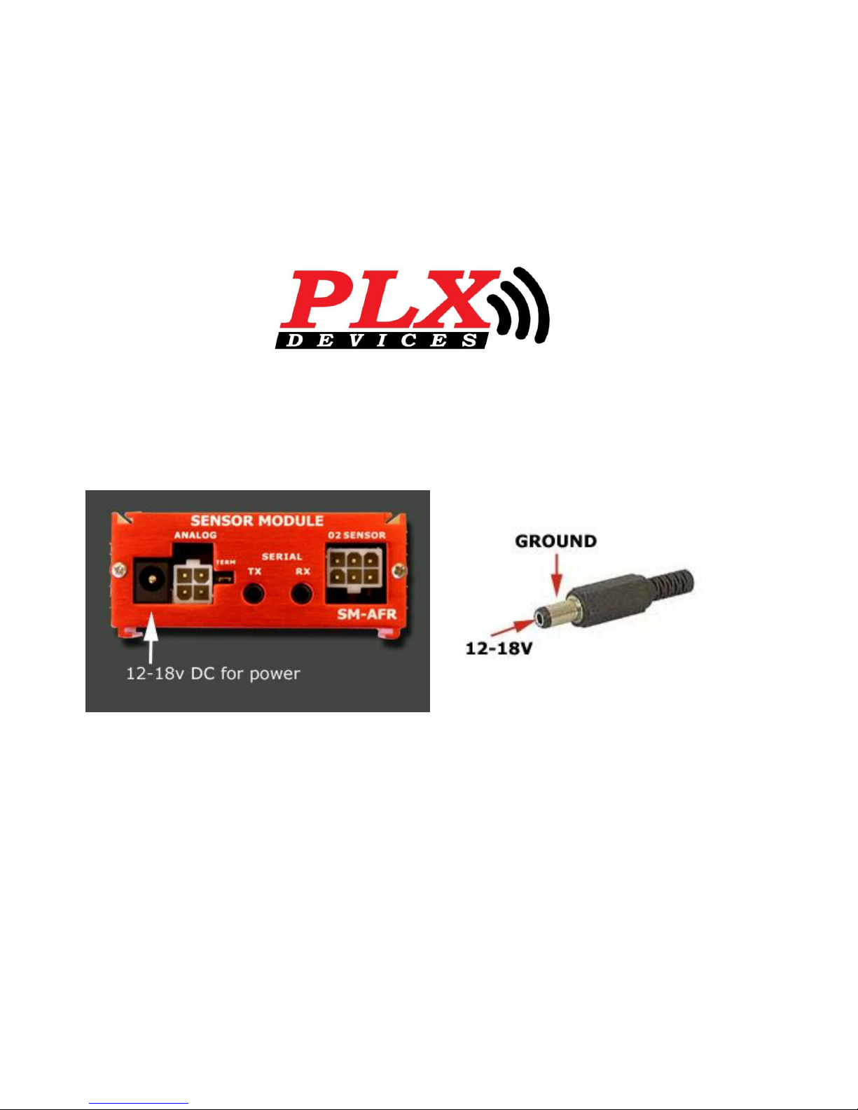
Tip: Find a power source that shuts off with ignition.
DO NOT POWER UP IN TILL INSTALL IS COMPLETE
• Step one
Find and connect to 12-18v power source (as shown below in picture)
Page 3
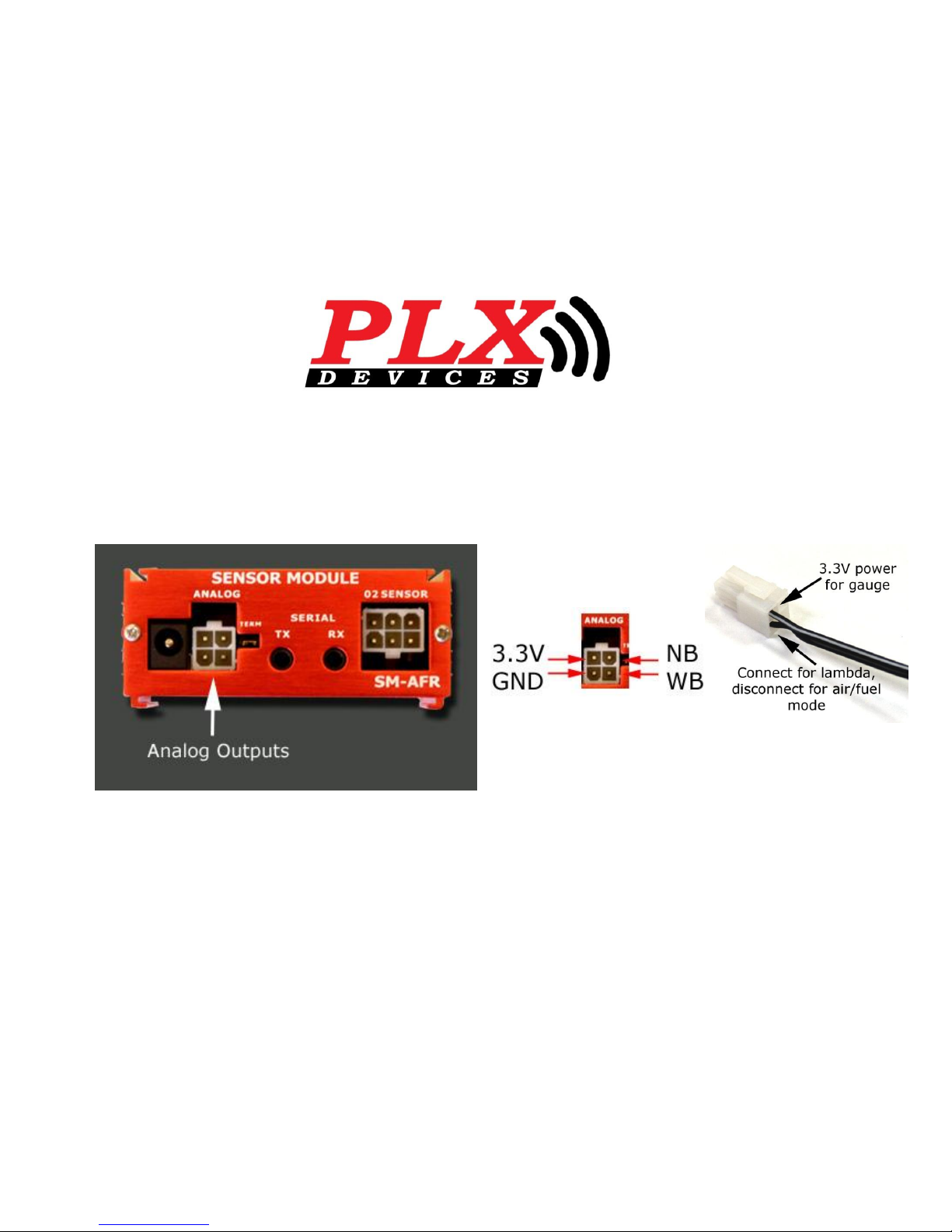
• Step Two
Connect Female Clip to Analog Output
Tip: Lambda wire comes disconnected from
the factory. Lambda wire only needed if using
alternative fuel other than gasoline.
Page 4
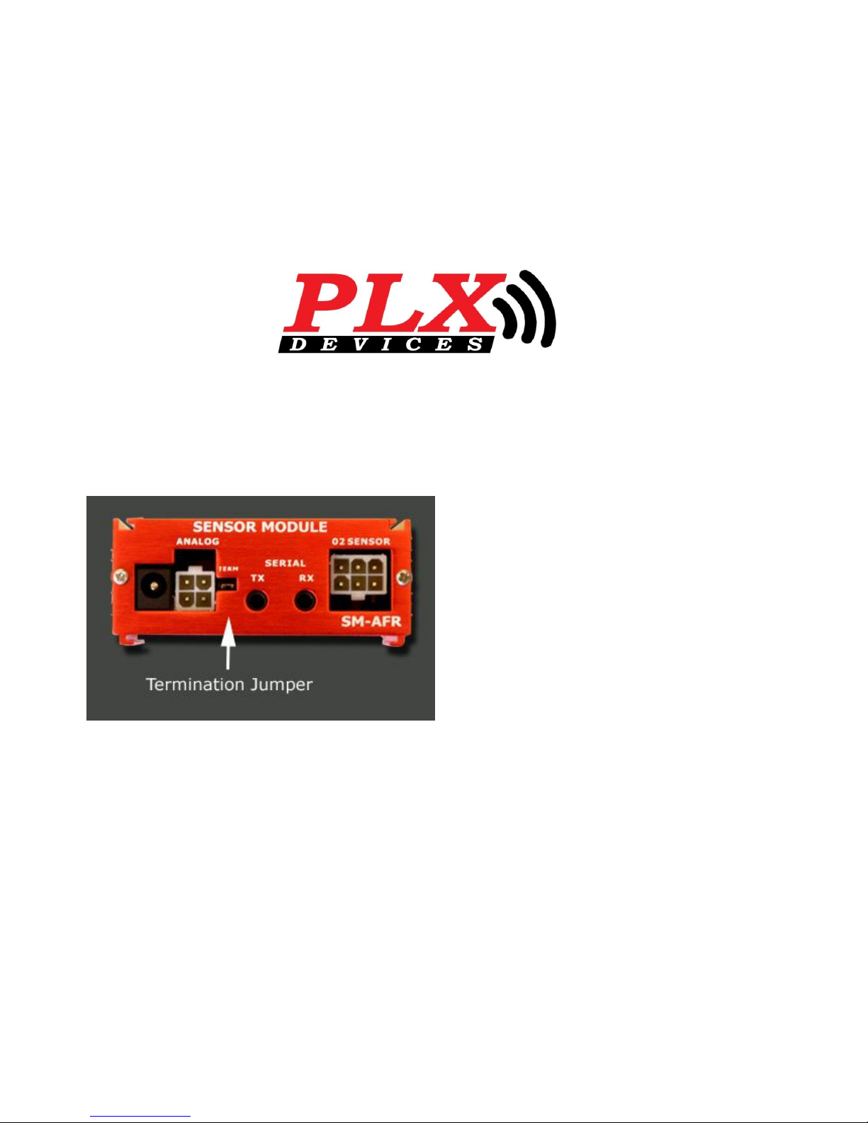
Tip: Jumper comes preinstalled from the
factory. Leave Jumper installed for this setup.
• Step Three
Terminal Jumper for first SM in iMFD daisy chain.
Page 5
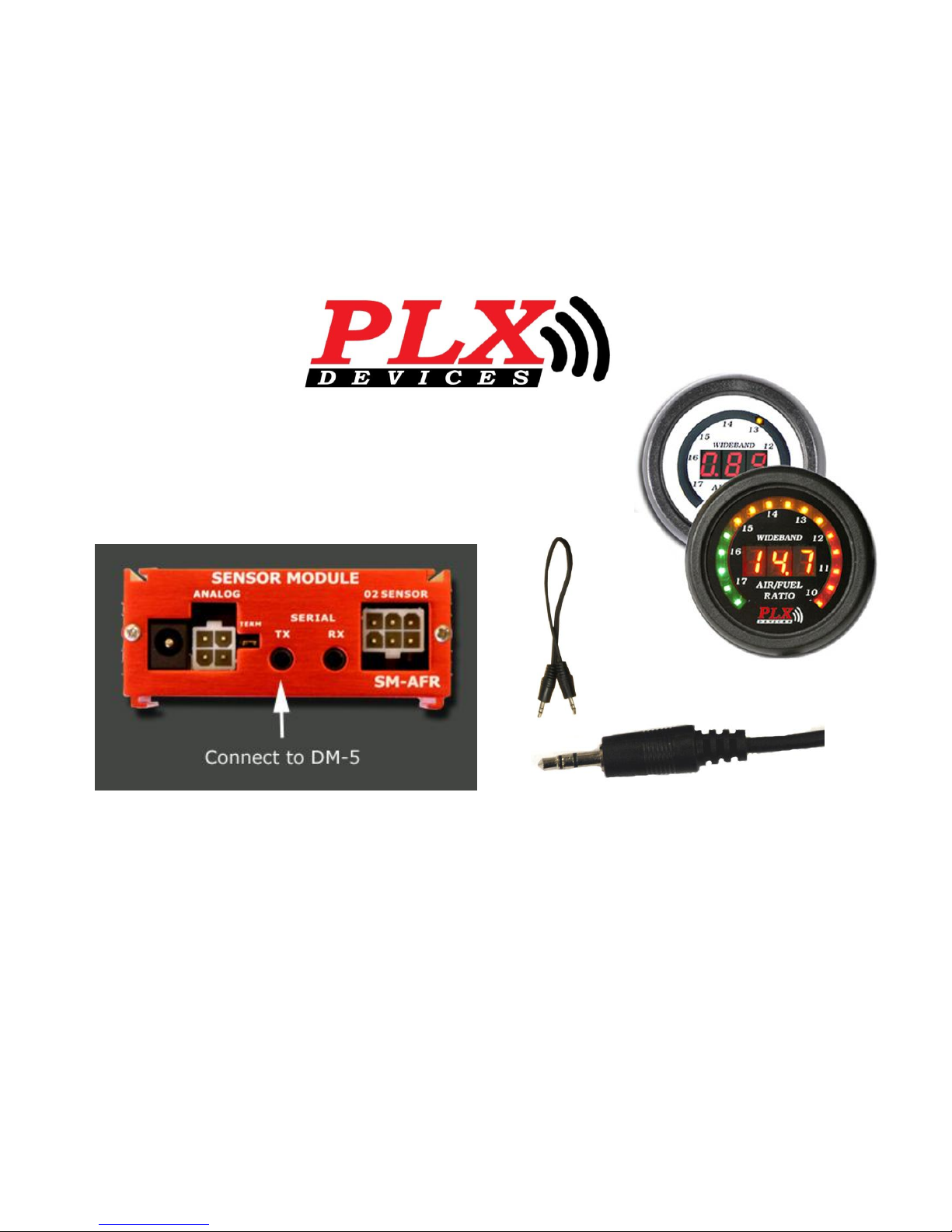
Tip: Do not use the serial cable (figure two) supplied in the kit for this application, it’s
use is for multiple SM Modules. Push DM-5 serial plug (figure one) firmly into TX
Serial input.
• Step Four
Connect DM-5 male end serial (figure one) to serial TX.
1.
X
2.
Page 6
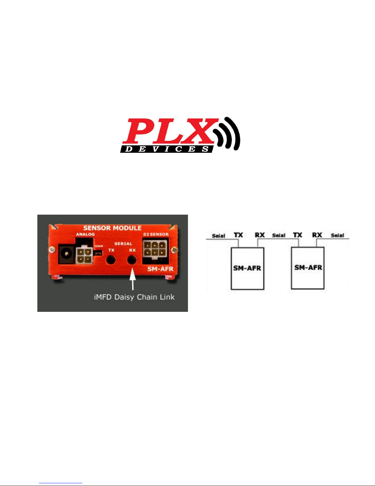
Tip: When connecting multiple SM Modules, remember to remove Terminal Jumper(s)
from every SM Module after the first in the iMFD in daisy chain.
Leaving the first SM Module with the Jumper installed.
• Step Five ( Not needed for stand alone setup)
RX connects to a second SM Module to daisy chain.
Page 7
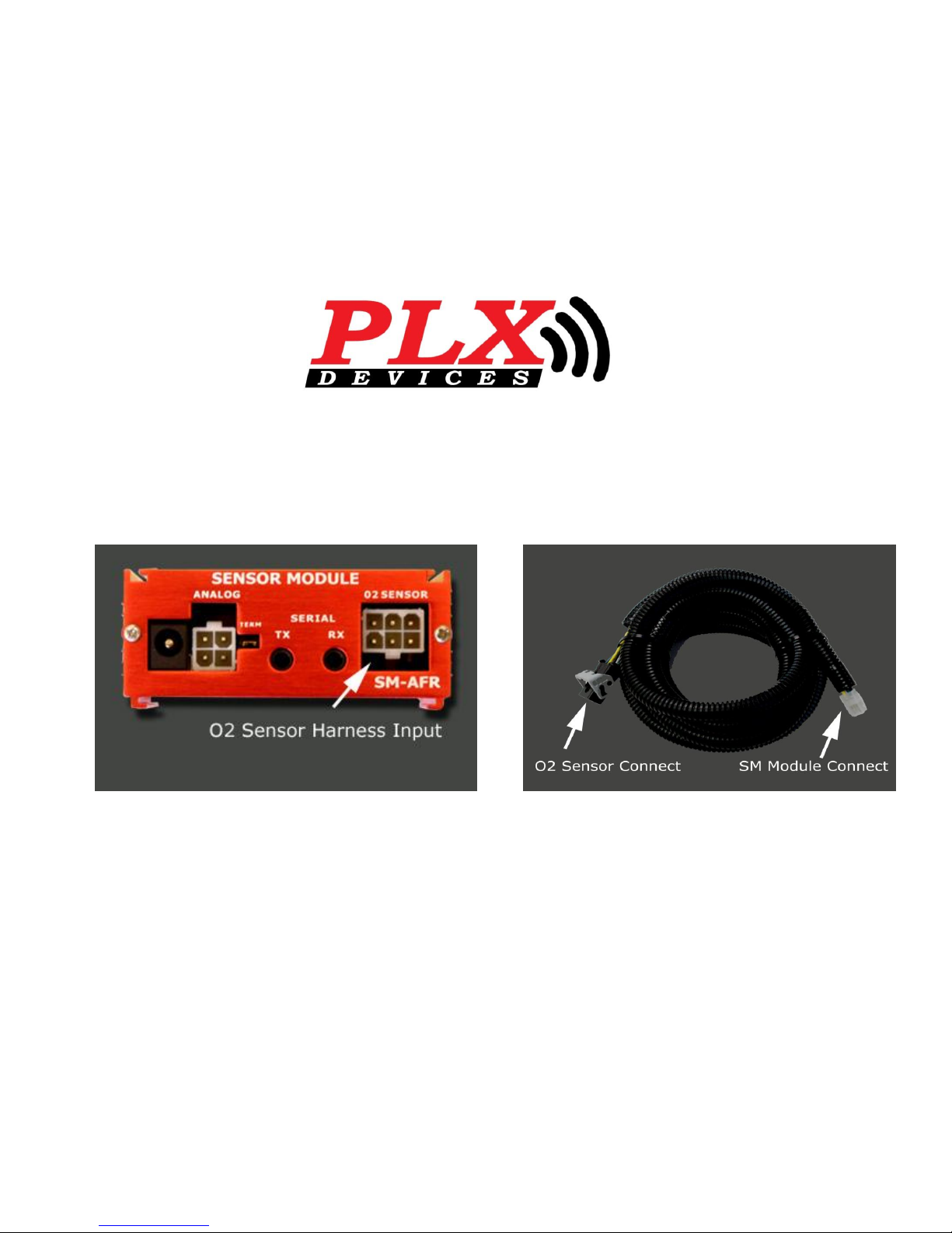
Tip: If routing O2 Harness through firewall use a grommet. Avoid harness from
coming in direct contact with exhaust. This will avoid damage to O2 Sensor Harness.
• Step Six
Connect O2 sensor harness (female end) to SM Module input.
Page 8
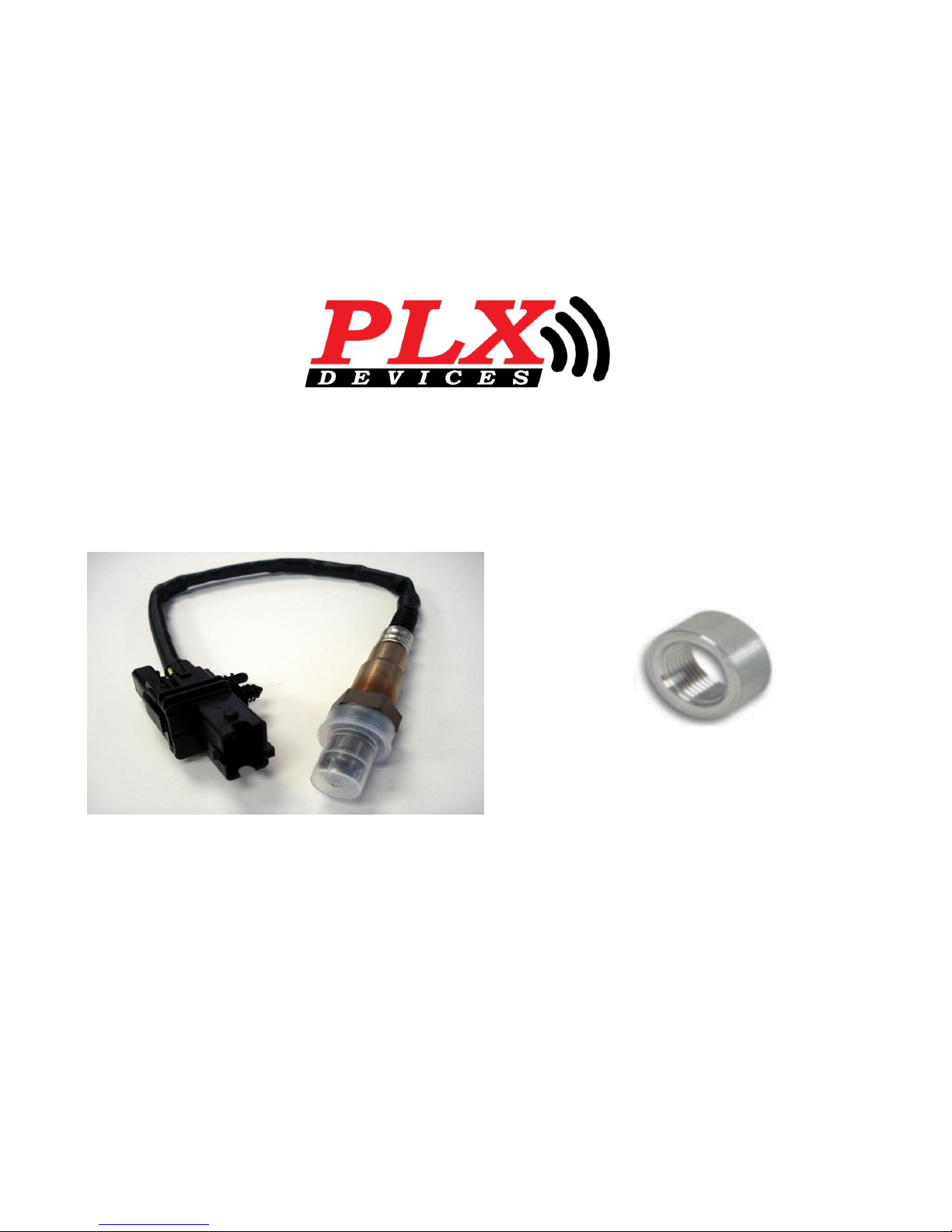
Tip: Mount the O2 Sensor before the catalytic converter or at least 24inch
downstream from your engine block for NA and 36inch for turbo engines for optimal
performance.
• Step Seven
Install the Wideband O2 Sensor. Install Bung (if applicable).
18mm X 1.5mm Bung
Page 9
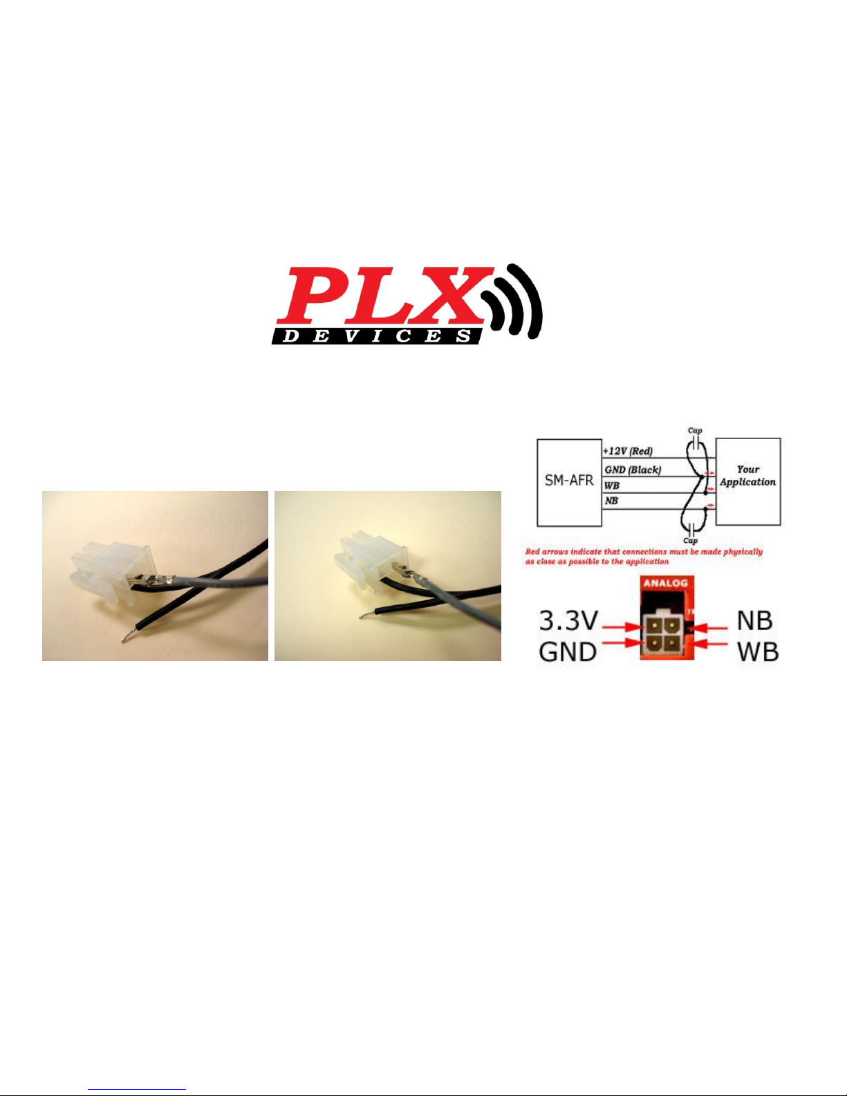
Tip: To interface with your ECU use the gray wire supplied in your SM-AFR Connect Kit
(as shown above). You will need to know the Diagram Pin Out of your specific vehicle.
• Step Eight ( Not needed for stand alone setup)
Connecting to ECU
NB Connection WB Connection
Page 10
www.plxdevices.com
408-745-7591
• Congratulations! Install is Complete.
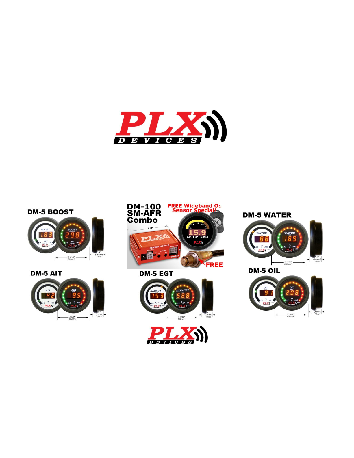
Checkout Some of are other iMFD products.
 Loading...