

Page 1
User’s Manual
HE-3200
English
Page 2
Important Safety Information
Please read this manual carefully before using the projector and keep
the manual handy for future reference.
CAUTION
RISK OF ELECTRIC SHOCK
DO NOT REMOVE SCREWS
EXCEPT SPECIFIED USER
SERVICE SCREW.
CAUTION: TO REDUCE THE RISK OF ELECTRIC SHOCK, DO
NOT REMOVE COVER. NO USER-SERVICEABLE PARTS INSIDE.
REFER SERVICING TO QUALIFIED SERVICE PERSONNEL.
This symbol warns the user that uninsulated voltage
within the unit may have sufficient magnitude to cause
electric shock. Therefore, it is dangerous to make any
kind of contact with any part inside of this unit.
This symbol alerts the user that important literature concerning the operation and maintenance of this unit has
been included. Therefore, it should be read carefully in
order to avoid any problems.
The above cautions are given on the bottom of the product.
CAUTION
To turn off main power, be sure to remove the plug from
the power outlet.
The power outlet socket should be installed as near to the
equipment as possible, and should be easily accessible.
WARNING
TO PREVENT FIRE OR SHOCK HAZARDS, DO NOT
EXPOSE THIS UNIT TO RAIN OR MOISTURE. ALSO DO
NOT USE THIS UNIT'S POLARIZED PLUG WITH AN EXTENSION CORD RECEPTACLE OR OTHER OUTLETS,
UNLESS THE PRONGS CAN BE FULLY INSERTED. REFRAIN FROM OPENING THE CABINET AS THERE ARE
HIGH-VOLTAGE COMPONENTS INSIDE. REFER SERVICING TO QUALIFIED SERVICE PERSONNEL.
DOC compliance Notice
This Class B digital apparatus meets all requirements of the Canadian
Interference-Causing Equipment Regulations.
WARNING
This equipment has been tested and found to comply with the limits for
a Class B digital device, pursuant to Part 15 of the FCC Rules. These
limits are designed to provide reasonable protection against harmful
interference in a residential installation. This equipment generates, uses
and can radiate radio frequency energy and, if not installed and used
in accordance with the instructions, may cause harmful interference to
radio communications. However, there is no guarantee that interference will not occur in a particular installation. If this equipment does
cause harmful interference to radio or television reception, which can
be determined by turning the equipment off and on, the user is encouraged to try to correct the interference by one or more of the following
measures:
• Reorientate or relocate the receiving antenna.
• Increase the separation between the equipment and receiver.
• Connect the equipment into an outlet on a circuit different from that
to which the receiver is connected.
• Consult the dealer or an experienced radio/TV technician for help.
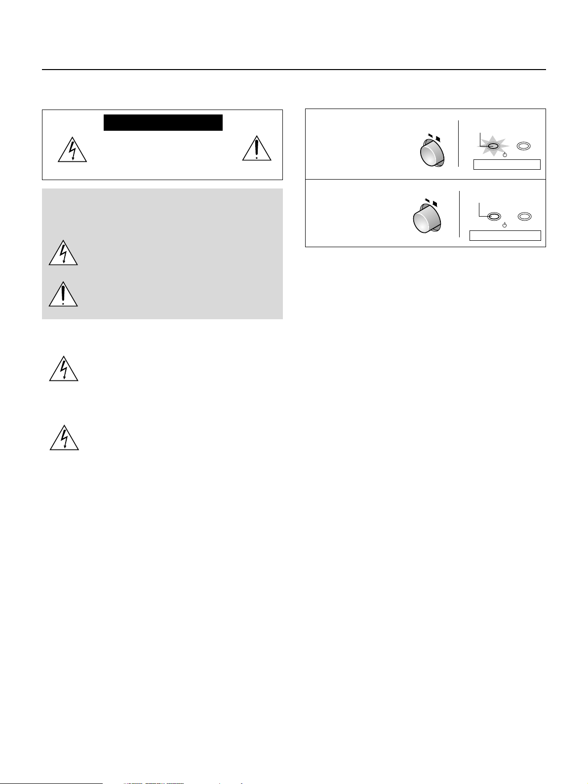
Tur ning ON or OFF Main Power
Make all hookups before turning on the main power.
To turn on the main power:
Press the POWER
switch down until it is in
the depressed position.
POWER
ON OFF
Light in orange
POWER
/
Main power ON
STATUS
On condition
To turn off the main power:
Press the POWER
switch until it is in the
protruded position.
POWER
ON OFF
Off condition
Indicator OFF
POWER
Main power OFF
STATUS
/
Installation
* Allow at least 10 cm (3.9 inch) of space between the projector top
panel and its surroundings.
Also allow at least 10 cm (3.9 inch) of other spaces around the projector.
* The projector should be placed on a flat, level surface and in a dry
area free from dust and moisture.
* The projector should always be handled with care. Dropping or jar-
ring the projector could damage internal components.
* If you wish to have the projector installed on the ceiling do not attempt
to install the projector yourself. The projector must be installed in accordance with any local building codes by qualified technicians in order to ensure proper operation and reduce the risk of bodily injury.
* Do not place this product near water, near a bathtub, in a wet base-
ment or near a swimming pool and the like.
Power supply
*
The projector is designed to operate on a power supply of 100-240V AC,
50/60Hz. Ensure that your power supply fits this requirement before attempting to use your projector.
* Handle the power cable carefully and avoid excessive bending. A
damaged cord can cause electric shock or fire.
* If the projector is not be used for an extended period of time, discon-
nect the plug from the power outlet. Do not unplug the power cable
from the wall outlet under the following circumstances, doing so may
cause damage to the projector:
Cleaning
* Unplug the projector before cleaning.
* Use a blower or lens paper to clean the lens, and be careful not to
scratch or mar the lens.
Lamp Replacement
Be sure to replace the lamp when the message "Replace The Lamp"
appears on the screen. If you continue to use the lamp after 1100
hours of usage, the lamp will not turn on. To replace the lamp, follow all
instructions on page E-46.
Fire and Shock Precautions
* The openings should never be covered or blocked by placing the
product on a bed, sofa, rug, or other similar surface.
* Prevent foreign objects such as paper clips and bits of paper from
falling into the projector. Do not attempt to retrieve any objects that
fell into the projector.
* Do not insert any metal objects such as a wire or screwdriver into
the projector. If something should fall into the projector, immediately
disconnect the power cord from the projector and have the object
removed by a qualified service person.
* Do not place any liquids on top of the projector.
E – 2
Do not look into the lens while the projector is on. Serious damage to your eyes could result.
Page 3
IMPORTANT SAFETY INSTRUCTIONS
1) Read these instructions.
All the safety and operating instructions should be read before the product is operated.
2) Keep these instructions.
The safety and operating instructions should be retained for future reference.
3) Heed all warnings.
All warnings on the product and in the operating instructions should be adhered to.
4) Follow all instructions.
All instructions should be followed.
5) Do not use this apparatus near water.
Do not use this product near water, near a bathtub, in a wet basement or near a swimming pool
and the like.
6) Cleaning
Clean only with dry cloth.
7) Ventilation
Do not block any ventilation openings. Install in accordance with the manufacturer's instructions.
8) Heat
Do not install near any heat sources such as radiators, heat registers, stoves, or other apparatus
(including amplifiers) that produce heat.
9) Grounding or Polarization
Do not defeat the safety purpose of the polarized or grounding-type plug. A polarized plug has
two blades with one wider than the other. A grounding type plug has two blades and a third
grounding prong. The wide blade or the third prong are provided for your safety. If the provided
plug does not fit into your outlet, consult an electrician for replacement of the obsolete outlet.
10) Power-Cable Protection
Protect the power cord from being walked on or pinched particularly at plugs, convenience receptacles, and the point where they exit from the apparatus.
11) Attachments/Accessories
Only use attachments/accessories specified by the manufacturer.
12) Transportation
Use only with the cart, stand, tripod, bracket, or table specified by the manufacturer, or sold with
the apparatus. When a cart is used, use caution when moving the cart/apparatus combination to
avoid injury from tip-over.
13) Lightning
Unplug this apparatus during lightning storms or when unused for long periods of time.
14) Servicing
Refer all servicing to qualified service personnel. Servicing is required when the apparatus has
been damaged in any way, such as power-supply cord or plug is damaged, liquid has been spilled
or objects have fallen into the apparatus, the apparatus has been exposed to rain or moisture,
does not operate normally, or has been dropped.
E – 3
Page 4

Major Features
High Image Quality
Use of a Digital Micromirror Device (DMDTM) chip that is based on
Texas Instrument's Digital Light Processing (DLP
enables images of high contrast and high detail.
䡵 DLP technology gives rise to devices that exhibit high response
speed, which in turn enables excellent moving picture characteristics and smooth images.
䡵 Use of a high-performance progressive scan converter provides
reproduction of film-like images.
䡵 Built-in color filters of high purity permit the reproduction of vivid
color images.
Quiet Design
PLUS Vision Corporation's quiet design technology has resulted
in a great reduction of fan noise which allows quiet performance
that doesn't interfere with the enjoyment of movie watching in an
indoor environment.
TM
) technology
Installation Flexibility
The compact design (of about B5 paper size: 182 x 257 mm / 7.2
x 10.1 inch) and mere 2 kg / 4.4 lbs weight has resulted in a projector that can be carried anywhere indoors for room-to-room
portability.
* Digital Light Processing, DLP, Digital Micromirror Device and DMD are trademarks of Texas Instru-
ments Incorporated.
* DLP technology is the combination of DLP technology and digitally control DMDTM, super micro
electronic components which replace LCD technology.
*VGA and XGA are trademarks or registered trademarks of International Business Machines Corpo-
ration in the USA.
* S-VGA is a registered trademark of Video Electronics Standards Association.
* TMDSI is a trademark of Silicon Image, Inc.
All company and/or product names are trademarks and/or registered trademarks of their respective
manufacturers.
E – 4
Page 5

Table of Contents
Important Safety Information ................................ E-2
IMPORTANT SAFETY INSTRUCTIONS ...................... E-3
Major Features ................................................. E-4
Accessories Check ............................................ E-6
Names of the Main Unit Parts ...............................E-7
Using the Storage Case ......................................................... E-9
Attaching the Supplied Adjusters .......................................... E-9
Names of the Remote Control Parts ...................... E-10
Preparing the Remote Control ............................. E-11
Inserting the Batteries ......................................................... E-11
Remote Control Range ........................................................ E-11
The Procedure Up to Projecting to the Screen .......... E-12
Placement Guide ............................................ E-13
Projection Distance and Screen Size ................................... E-13
Power Cord Connections ................................... E-16
Power Cord Connections ..................................................... E-16
Connecting Video Equipment and Personal Computers
Connections with VIDEO and S-VIDEO Connectors ............. E-17
Connections with YCbCr/YPbPr Connectors ....................... E-18
Connection with RGB and DVI-D Connector ........................ E-19
...... E-17
Turning ON or OFF Main Power ........................... E-21
Tur ning ON or OFF Main Power ........................................... E-21
Tur ning ON or OFF Power.................................................... E-21
Adjustment of the Projection Screen ..................... E-22
Projection Screen Position Adjustment ............................... E-22
Adjustment of Screen Size and Focus ................................. E-22
Input Selection .................................................................... E-23
Selection of Aspect Ratio .................................................... E-23
Input Screen and Aspect Ratio Selection Screen ................. E-24
Operation with the Remote Control ....................... E-25
Tur ning ON Power/STANDBY .............................................. E-25
Input Selection .................................................................... E-26
Selection of Aspect Ratio .................................................... E-27
Automatic Adjustment of the Input Signal ........................... E-27
Using the On-Screen Menu ................................ E-28
Menu List ..................................................... E-31
Video Adjustments [Picture 1]............................. E-33
Adjusting the Brightness ..................................................... E-33
Adjusting the Contrast ......................................................... E-33
Adjusting the color .............................................................. E-33
Adjusting the tint ................................................................. E-34
Adjusting the Sharpness ..................................................... E-34
Adjusting the White Balance ................................................ E-34
Adjusting the Clock Frequency of the Input Signal .............. E-35
Adjusting the Phase of the Input Signal .............................. E-35
Input Video Adjustments [Picture 2] ...................... E-36
Adjusting the Sharpness of the Video Image ....................... E-36
Adjusting the Sharpness When Expanding/Compressing ....E-36
ProScan Mode Settings ....................................................... E-36
Movement of Screen Display Position ................................. E-37
Gamma Settings .................................................................. E-37
Video Signal Color System Settings .................................... E-38
Format Settings ................................................................... E-38
Color Space Settings ........................................................... E-38
Setting of White Emphasis .................................................. E-38
Setup .......................................................... E-39
Adjustment of Keystone Distortion ...................................... E-39
Screen Projection System Settings ..................................... E-39
Background Color Settings .................................................. E-40
Auto Standby Settings ......................................................... E-40
LED Display Settings ........................................................... E-40
On-Screen Display Settings [Option] ..................... E-41
On-Screen Display Language Settings ................................ E-41
Moving the Menu Display Position ......................................E-41
On-Screen Display Duration Setting .................................... E-41
Resetting, Storing, and Information [Info.] ............. E-42
Saving and Loading of Video Adjustments .......................... E-42
Returning to Standard Settings ........................................... E-43
Resetting the Lamp Timer ................................................... E-43
Viewing the Lamp Timer/Resolution and Frequency............ E-43
Troubleshooting.............................................. E-44
When the STATUS Indicator Is Lit/Flashes............... E-45
Replacing the Lamp Cartridge............................. E-46
Cleaning ...................................................... E-48
Table of Supported Frequencies .......................... E-49
Specifications ................................................ E-50
Main Unit External View .................................... E-51
E – 5
Page 6
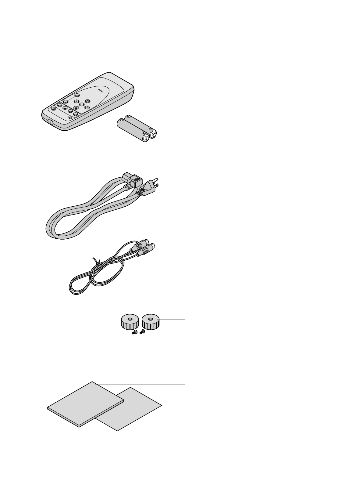
Accessories Check
Remove the main unit and the accessories from the box and check that the following items are included.
Should an accessory be missing, please contact your store of purchase.
Remote control⳯1
ESC
MENU
I
V
I
V
D
B
Y
G
B
R
D
N
A
T
/S
N
O
BD
G
R
r
bP
P
O
E
ID
V
CT
E
P
SET
V
C
/Y
SV
O
IDE
V
-
S
S
A
Controls the projector.
AA Batteries⳯2
These batteries are for the remote control. Insert the batteries
at time of purchase.
See → Page E-11.
Power cable (1.8 m / 5.9 feet)
This power cord supplies power to the unit. See → Page E-16
about connections.
User's Manual
Quick Start Guide
S-Video cable (3 m / 9.8 feet) No. 771709100
This cable is used when the output connector of the equipment
to be connected is an S-video connector. Connections are described on → Page E-17.
Adjuster⳯2 / Screw⳯2
The adjusters and screws are required for fine vertical adjustment of the projector.
See → Page E-9 for attachment and Page E-22 for adjustment.
Users Manual⳯1
Includes information about handling of the projector, the operation method, and precautions.
Quick Start Guide⳯1
Consolidates the procedures from setup to projecting the picture.
E – 6
Page 7
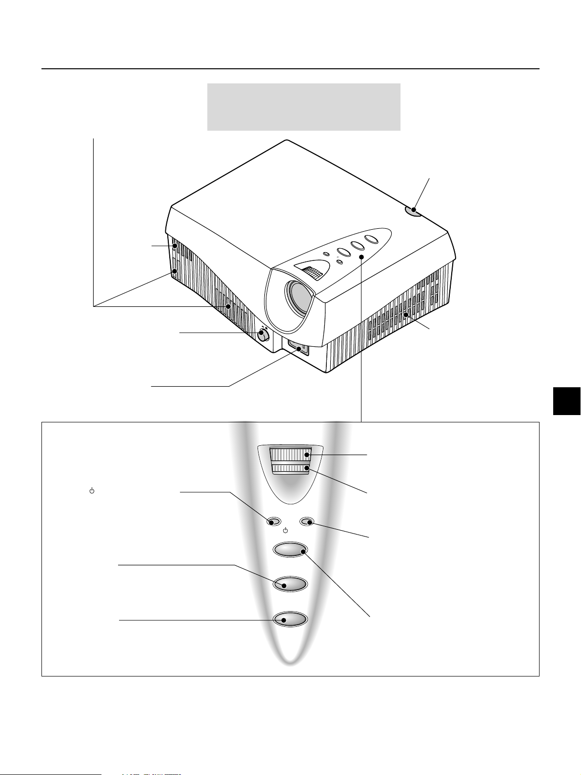
Names of the Main Unit Parts
Attention!
Ventilation outflow holes
These ventilation outflow holes used for cooling
the main unit and discharge the heat of the lamp.
Air intake hole
POWER switch
This is the main power
switch. → Page E-16
Pay special attention to the ventilation outflow
holes. The heat from the lamp is discharged
from the ventilation outflow holes.
T
C
Y
B
D
N
A
S
T
U
S
/
T
A
N
T
O
S
/
R
E
W
O
P
PO
W
O
ER
N
O
FF
Remote control sensor
The remote control signal is received
here. → Page E-11
E
C
R
U
O
S
E
P
S
A
Air intake hole
This is an air intake hole used for
cooling the main unit.
AC IN connector
The supplied power cable is
connected here. → Page E-16
POWER/ (STANDBY) indicator
On and Standby operation modes are indicated when this
indicator is flashing green or lit orange. The indicator is not lit
when the POWER switch is "off." → Page E-21
ASPECT button
This button selects the aspect ratio (i.e., the ratio of
screen width and height) of the input video. → Page E-23
SOURCE button
This button selects the input sugnal of the main unit
that will be used for the connections . → Page E-23
POWER/STATUS
ON/STANDBY
ASPECT
SOURCE
FOCUS ring
This adjusts the focus of the projected picture.
→
Page E-22
ZOOM ring
This adjusts the size of the projected picture.
→
Page E-22
STATUS indicator
Lit/flashing serve to indicate the main unit temperature,
lamp, lamp cover, lamp cartridge, and fan conditions.
→
Page E-45
ON/STANDBY button
This button is used to switch ON the power and set the unit
to the STANDBY mode. → Page E-21
E – 7
Page 8
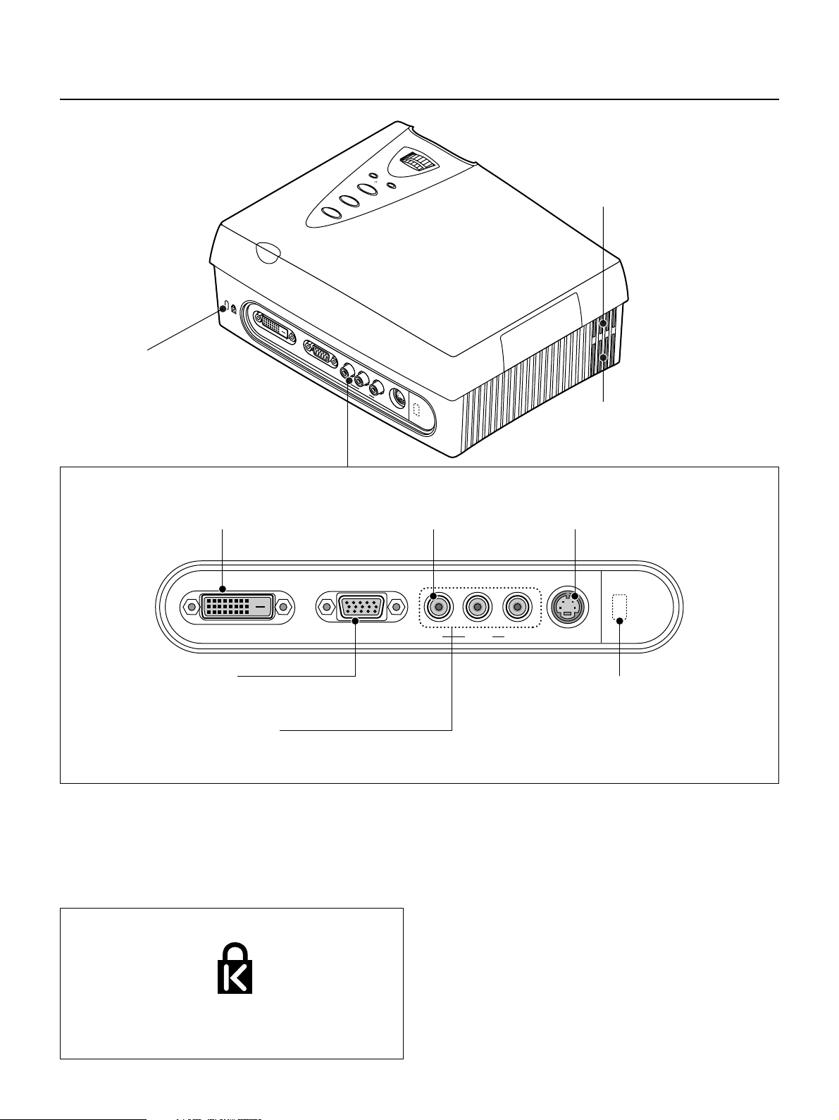
Names of the Main Unit Parts
Theft prevention locking hole
(See below)
DVI-D connector
This is connected with the (24-pin) DVI-D output
connector of the equipment to be connected. → Page E-19
DVI-D RGB
VIDEO connector
This is connected with the VIDEO output connector
of the equipment to be connected. → Page E-17
P
O
W
E
R
/
S
T
A
T
O
U
N
/
S
S
T
A
N
D
B
Y
A
S
P
E
C
T
S
O
U
R
C
E
VIDEO
Y
Pb/Cb
Pr/Cr
S-VIDEO
Air intake hole
This is an air intake hole used for cooling the main unit.
Ventilation outflow hole
This ventilation outflow hole is used for cooling the
main unit and discharges the heat of the lamp.
S-VIDEO connector
This is connected with the S-VIDEO output connector of the
equipment to be connected. → Page E-17
VIDEO
DVI-D RGB
RGB Connector
This is connected with the RGB output connector (mini D-Sub
15 pin) of the equipment to be connected. → Page E-17
YPbPr/YCbCr Connector
This is connected with the YPbPr output connector or YCbCr output
connector of the equipment to be connected. → Page E-18
Theft Prevention Lock
The theft prevention lock is supported by the Micro Saver
Security System manufactured by Kensington Technology
Group.
Pb/Cb
Y
Pr/Cr
S-VIDEO
CTRL connector
This connector is for service personnel only.
(A seal is applied prior to shipping from the factory.)
End users should not use this connector. Doing so by
end users may cause breakdown.
E – 8
Page 9
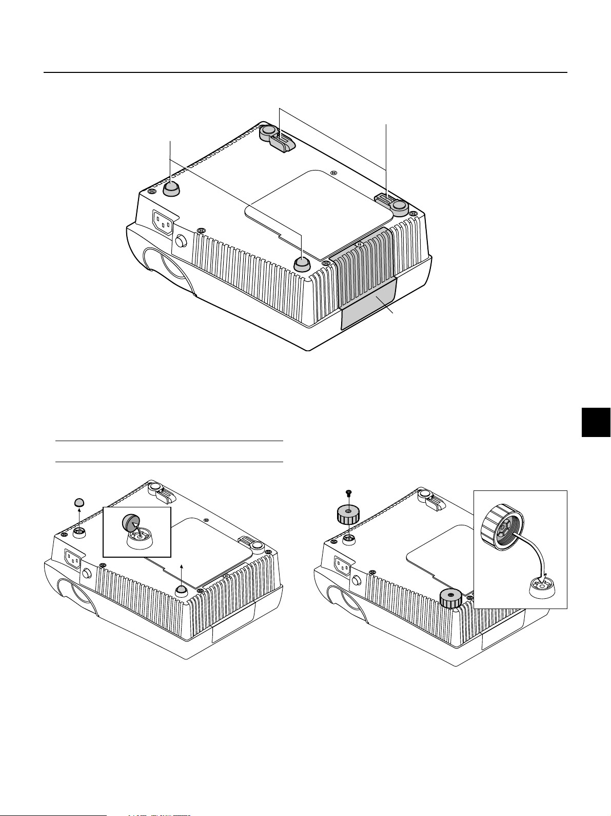
Front adjuster
These feet are used for height
adjustment. → (See below)
Names of the Main Unit Parts
Rear adjuster
These feet are used for height
adjustment. → Page E-22
Lamp cover
This cover is removed when replacing the lamp
cartridge of the light source. → Page E-46
Attaching the Supplied Adjusters
The supplied adjusters are required for vertical adjustment of the projector.
See → Page E-22 about "Using the Adjusters"
1. Remove a rubber pad of each front foot.
Note: The rubber pads are bonded. Being carful not to mar the plastic
part of the front feet, remove the rubber pads.
2. After putting projections on the back of the supplied adjuster into
depressions of the front feet, tighten the screws.
E – 9
Page 10
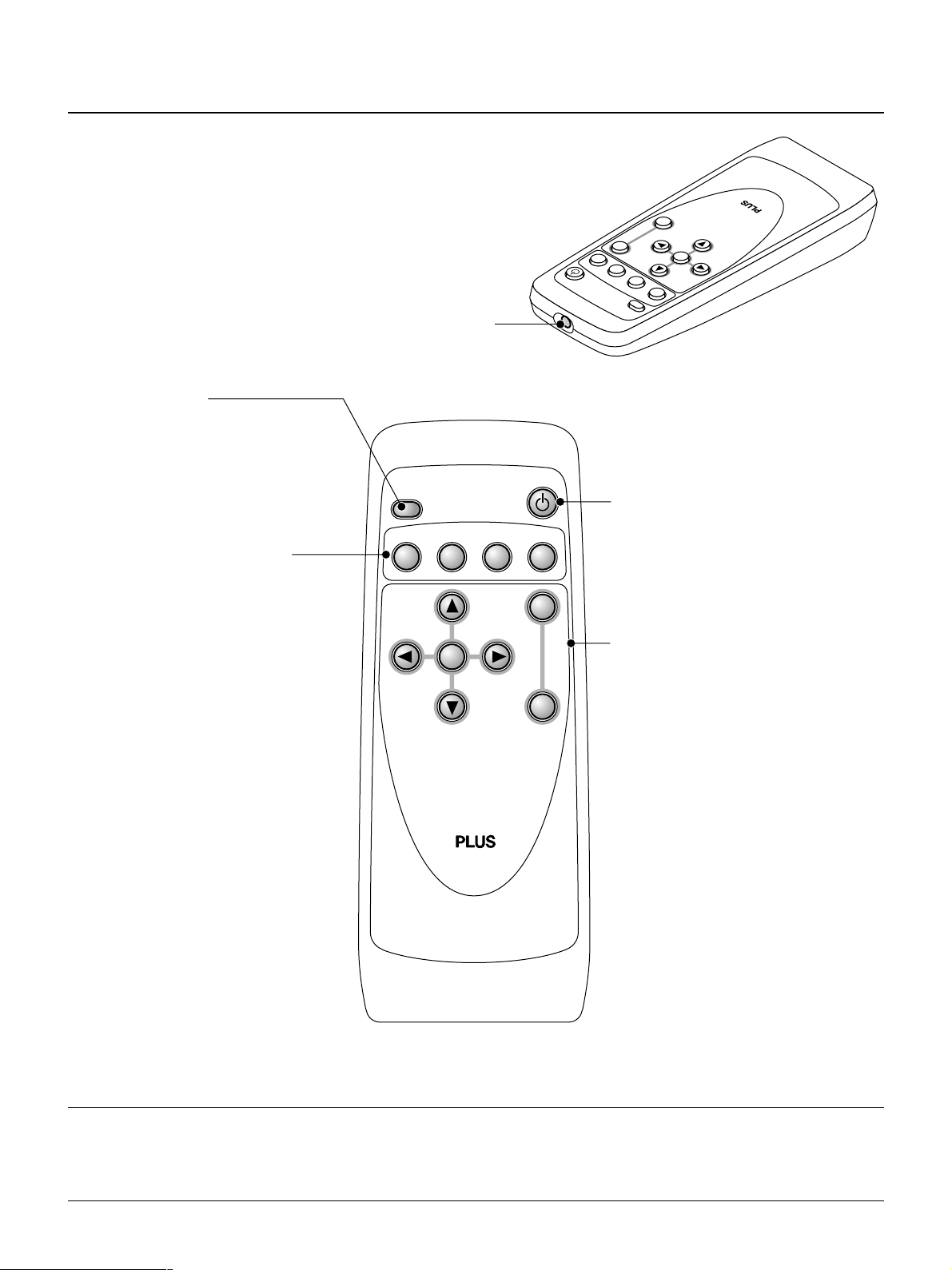
Names of the Remote Control Parts
SE
T
E
SC
M
ENU
ASPECT
VIDEO
/YPbPr
ON/STANDBY
S
-
VIDEO
RGB
DVI
SV
CV
RGB
DVI
Remote control transmitter
The infrared signal is sent from this part.
ASPECT button
This button selects the vertical and horizontal ratio
of the screen of the input video.
→
Page E-23
These buttons are used for the
selection of the input.
For further information about input selection, see
→
Page E-23
S-VIDEO button
This switches the input to the S-VIDEO signal.
VIDEO/YPbPr button
This switches the input to the VIDEO, YCbCr, or
YPbPr signal.
RGB button
This switches the input to the RGB signal.
DVI button
This switches the input to the DVI-D signal.
ASPECT
S
VIDEO
-
VIDEO
/YPbPr
SV CV RGB DVI
SET
ON/STANDBY
RGB
DVI
MENU
ESC
ON/STANDBY button
This button is used to switch ON the power and set the unit
to the STANDBY mode. → Page E-21
These buttons are used for menu operations.
→
Page E-28 "Using the On-Screen Menu"
MENU button
This is used in the selection of the menu name when
displaying the menu on the projection screen.
ESC button
This is used when closing the menu.
SET button
This is used to set the menu items.
Automatic adjustment of the RGB input signal is performed
when the menu is closed.
Cursor buttons (왗 왘왖왔)
These are used in the selection of the menu name, item
name, and contents.
Note: Handling of the Remote Control
* Do not drop the remote control or handle it inappropriately.
* Do not expose the remote control to water or other liquids. Should the remote control become wet, wipe it dry immediately.
*Try to avoid use in hot and/or humid locations.
* Remove the batteries from the remote control when it is not going to be used for a long period.
* Some operations (such as menu operations) are available only through the use of the remote control and attention should be given to its careful use.
E – 10
Page 11
Preparing the Remote Control
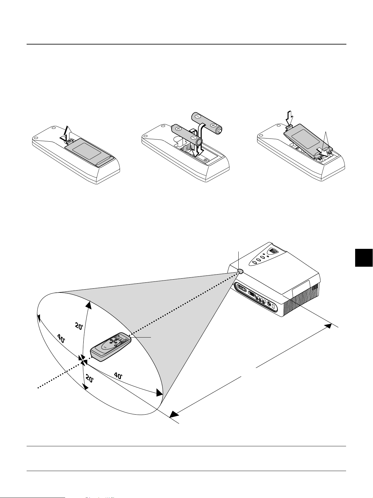
Inserting the Batteries
When using the remote control for the first time, install the batteries that were supplied.
When replacing batteries, purchase two of the same type of AA battery.
Press and at the same time lift
the battery case cover at the
1
rear of the remote control to
remove it.
Remote Control Range
Point the remote control toward the remote control sensor located at the rear of the main unit and operate.
The range over which the main unit will receive the remote control signal is roughly as follows: within 20° above and 20° below a
line perpendicular with respect to the sensor and within 40° to the left and 40° to the right. The transmission range is about 7 m /
23.0 feet.
Follow the markings on the inside
of the case and insert the batter-
2
ies in the correct plus (+) and minus (-) directions.
Remote control transmitter
First insert the tabs of the battery
case cover, then press it closed.
3
Tabs
Remote control
sensor
Approximately 7 m / 23.0 feet
Note:
* Exposure of the main unit's remote control sensor or the remote control transmitter to bright light or the obstruction of the signal by an obstacle located in the
pathway may prevent operation.
* The remote control will not function when the batteries are exhausted.
E – 11
Page 12
The Procedure Up to Projecting to the Screen
E
C
R
U
O
S
T
C
E
P
S
8
A
Y
B
D
N
A
S
T
U
S
T
/
A
N
T
O
S
/
R
E
W
O
P
9
4
POW
ON OFF
5
7
ER
6
1
2
3
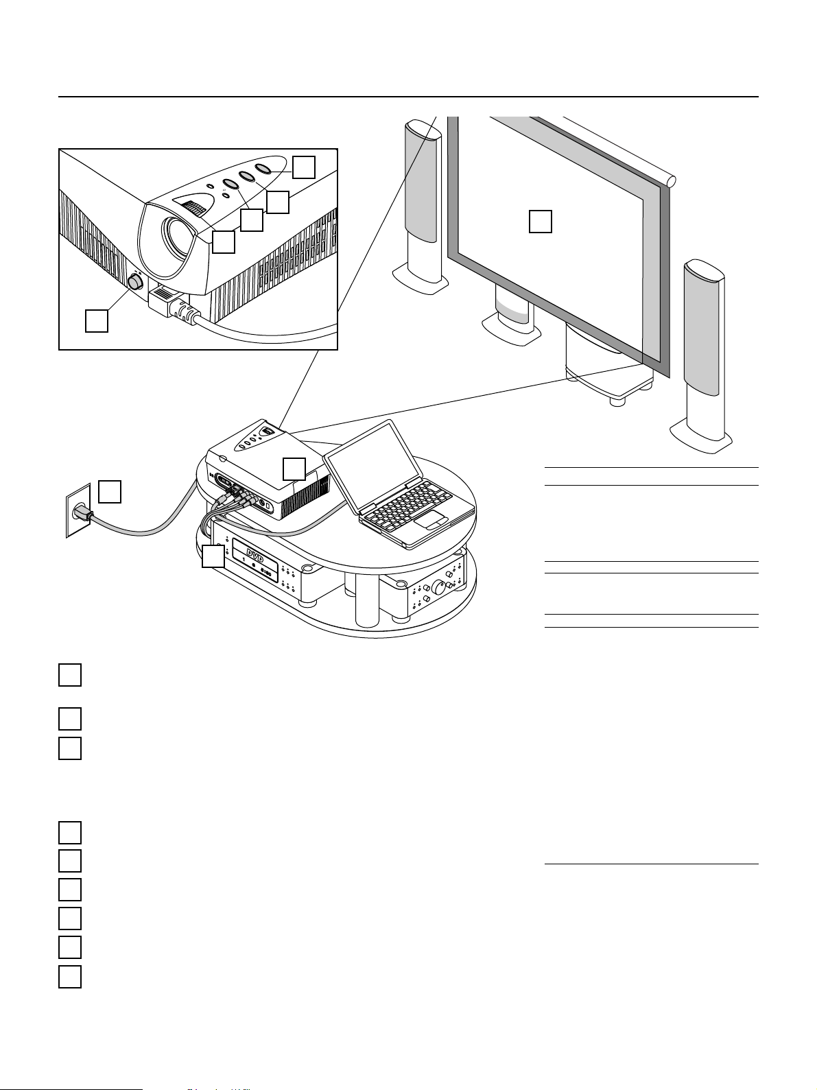
Position the projector → Page E-13 "Projection Distance and Screen Size"
1
2
3
4
5
Determine the locations to place the screen and the projector.
Connecting the power cable → Page E-16 "Power Cord Connections"
Connect the video equipment and personal computer
Connect your equipment to the projector.
→ Page E-17 "Connections with VIDEO and S-VIDEO Connectors"
→ Page E-18 "Connections with YCbCr Connectors (COMPONENT)"
→ Page E-19 "Connections with RGB and DVI-D Connector"
Switching on the main power → Page E-21 "Turning ON or OFF Main Power"
Switching on the power → Page E-21 "Turning ON or OFF Power"
About DLP projectors
Though careful attention is paid to providing
optimum quality, please note that with DLP
type projectors, in rare cases there may be
black spots or bright spots among the picture elements.
Note: During projection, some streaks of light may
be visible outside of the projected picture; this is
not a product fault.
Note:
* Please purchase a commercially available screen
separately.
*A commercially available cable is required for the
connection with the RGB connector of the personal computer and an optional cable (Order code
27-060) is required for the connector with the
DVI-D connector.
* An optional cable (Order code 27-062) is required
for the connection of a DVD player or high definition video equipment with the YPbPr/YCbCr
connector.
*A commercially available video cable is required
for the connection of video equipment with the
VIDEO connector.
* Please refer to the various manuals of the audio
system for information about audio system connections.
6
7
8
9
E – 12
Properly adjust the projection image to the screen → Page E-22 "Projection Screen Position Adjustment"
Properly adjust the screen size and focus → Page E-22 "Adjustment of Screen Size and Focus"
Selecting input equipment → Page E-23, 26 "Input Selection"
Selecting the vertical and horizontal aspect of the picture (i.e., the ratio of screen width and height)
→ Page E-23, 27 "Selection of Aspect Ratio (i.e., Ratio of Screen Width to Screen Height)"
Page 13
Placement Guide
Use this information as a guide to find the rough screen size when the projector is placed at a certain location, or to find out the
approximate size of a screen that will be required.
The projection distance over which focussing is adjustable is 1.2 m (3.9 feet) to 7.6 m (24.9 feet) from the lens surface of the main
unit. The projector should be placed within this range.
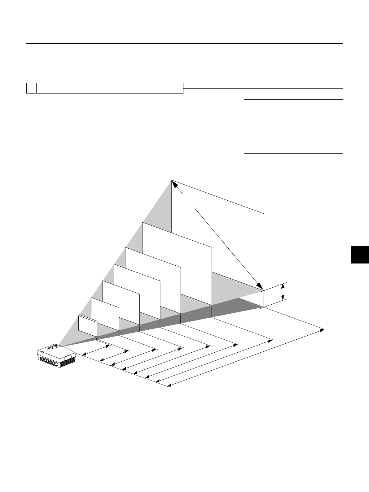
1 Projection Distance and Screen Size
Screens with 4:3 Aspect Ratio (at an output size of 800 x 600)
This projection screen aspect ratio supports multiple uses.
The screen is placed within the projection distance range that corresponds to the screen
size designation. Within this range, the screen size can be adjusted with the zoom ring.
120.0 (wide) x 90.0 (high) inch
304.8 (wide) x 228.6 (high) cm
96.0 (wide) x 72.0 (high) inch
243.8 (wide) x 182.9 (high) cm
80.0 (wide) x 60.0 (high) inch
203.2 (wide) x 152.4 (high) cm
64.0 (wide) x 48.0 (high) inch
162.6 (wide) x 121.9 (high) cm
48.0 (wide) x 36.0 (high) inch
121.9 (wide) x 91.4 (high) cm
32.0 (wide) x 24.0 (high) inch
81.3 (wide) x 61.0 (high) cm
30.4 (wide) x 22.8 (high) inch
77.2 (wide) x 57.9 (high) cm
40 inch
60 inch
Screen Size
160.0 (wide) x 120.0 (high) inch
406.4 (wide) x 304.8 (high) cm
150
inch
120
inch
100
inch
80 inch
Screen Size Designation (Inches)
200
inch
Note: This is the projection distance (at an output
size of 800 x 600) for aspect ratio settings of "Full"
or "Auto." The projection distance will differ when
"Thru" or other settings have been selected and the
image is projected to fill the screen. When establishing a fixed placement, the distance could be outside the zoom adjustment range and a test projection should be conducted. → Page E-24 "Input
Screen and Aspect Ratio Selection Screen"
H
38 inch
1.2 –1.4m
3.9 – 4.6 feet /
Lens surface of
the main unit
1.3 –1.5m
4.3 – 4.9 feet /
6.2 – 7.2 feet / 1.9 – 2.2m
8.5 – 9.8 feet / 2.6 – 3.0m
10.5 –12.5 feet / 3.2 – 3.8m
12.5 –15.1feet / 3.8 – 4.6m
15.7–18.7 feet / 4.8 – 5.7m
Wide to Telephoto
Projection Distance
H dimension: Height from center of projector lens to bottom edge of screen.
200 inch: 23.9 inch/60.6 cm 150 inch: 17.9 inch/45.5 cm 120 inch: 14.3 inch/36.4 cm 100 inch: 11.9 inch/30.3 cm
80 inch: 9.6 inch/24.3 cm 60 inch: 7.2 inch/18.2 cm 40 inch: 4.8 inch/12.1 cm 38 inch: 4.5 inch/11.5 cm
21.0 – 24.9 feet / 6.4 – 7.6m
E – 13
Page 14
Placement Guide
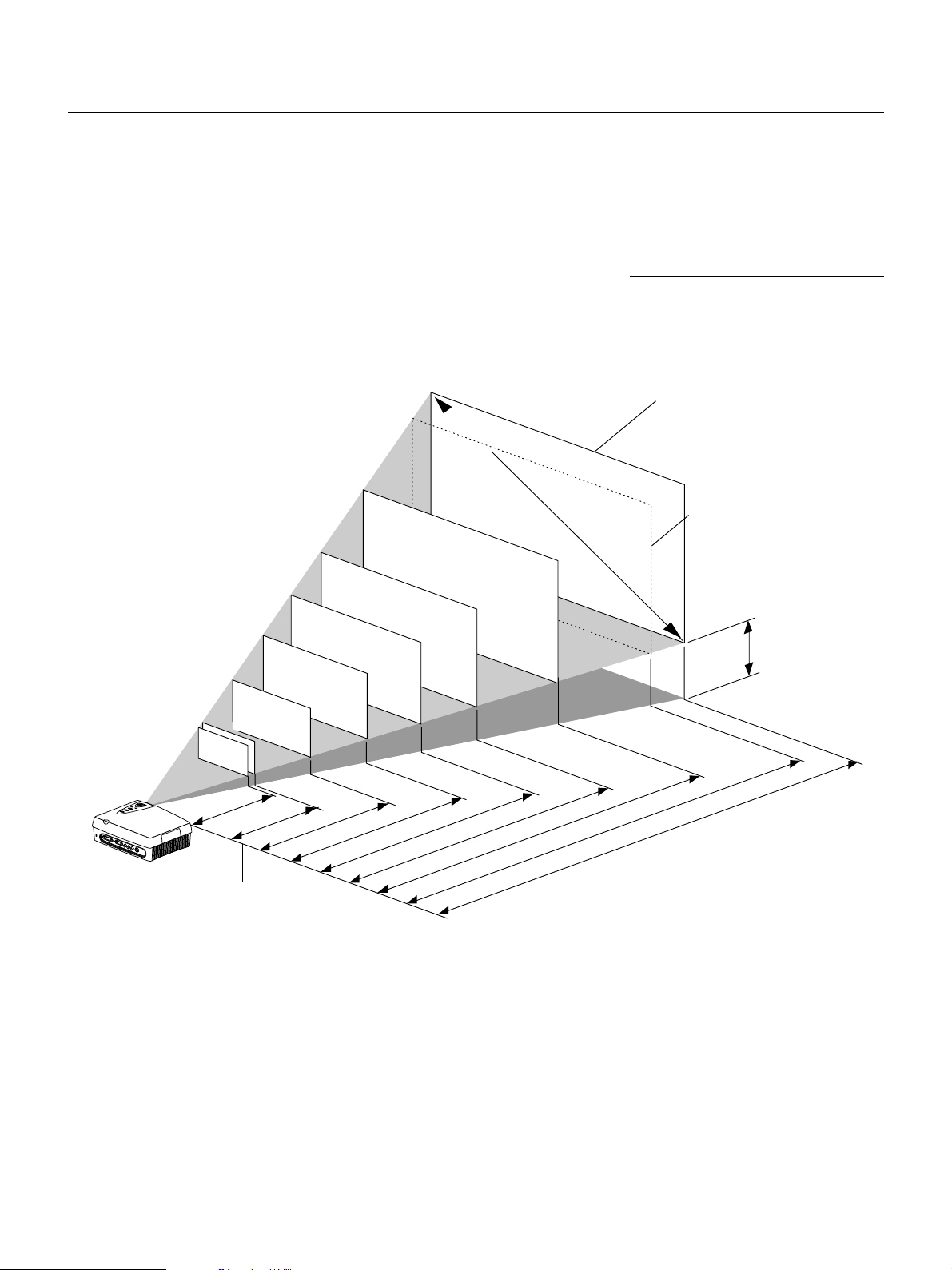
Screens with 16:9 Aspect Ratio (at an output size of 848 x 480)
These are the projection distances for screens of 16:9 aspect ratio used for the viewing
of DVD and other squeezed screen applications.
This projector uses an output size of 848 x 480 pixels for home theater applications and
enables the projection of a high definition 16:9 aspect ratio.
The screen is placed within the projection distance range that corresponds to the screen
size designation. Within this range, the screen size can be adjusted with the zoom ring.
Screen Size
104.5 (wide) x 58.8 (high) inch
265.3 (wide) x 150.1 (high) cm
87.1 (wide) x 49.0 (high) inch
221.1 (wide) x 125.1 (high) cm
69.7 (wide) x 39.2 (high) inch
176.8 (wide) x 100.1 (high) cm
52.2 (wide) x 29.4 (high) inch
132.6 (wide) x 75.1 (high) cm
34.8 (wide) x 19.6 (high) inch
88.4 (wide) x 50.1 (high) cm
33.1 (wide) x 18.6 (high) inch
84.0 (wide) x 47.6 (high) cm
40
inch
169.9 (wide) x 95.6 (high) inch
431.6 (wide) x 242.8 (high) cm
160.3 (wide) x 90.2 (high) inch
406.4 (wide) x 228.6 (high) cm
130.7 (wide) x 73.5 (high) inch
331.6 (wide) x 187.7 (high) cm
150
120
inch
100
inch
80
inch
60
inch
Screen Size Designation (Inches)
195
inch
184
inch
inch
Note: This is the projection distance when an aspect ratio of [16:9] has been selected. Selection of
"Full", "Auto" or other settings at this projection distance will result in the top and bottom of the image
extending beyond the screen. When establishing a
fixed placement, the distance could be outside the
zoom adjustment range and a test projection should
be conducted. → Page E-24 "Input Screen and Aspect Ratio Selection Screen"
Maximum screen size that allows
focussing of a 16:9 aspect ratio image with 848 x 480 output size
This is the distance when an
image of 16:9 aspect ratio is
projected to horizontally fill a
200" 4:3 aspect ratio screen.
H
38
inch
1.3 –1.4m
4.3 – 4.5 feet /
4.3 – 4.9 feet /
Lens surface of
1.3 –1.5m
6.6 – 7.5 feet / 2.0 –2.3m
8.9 –10.2 feet / 2.7 – 3.1m
10.8 –12.8 feet / 3.3 – 3.9m
13.1–15.4 feet / 4.0 – 4.7m
16.4 –19.4 feet / 5.0 – 5.9m
19.7– 23.6 feet / 6.0 – 7.2m
Wide to Telephoto
Projection Distance
21.0 – 24.9 feet / 6.4 –7.6m
the main unit
H dimension: Height from center of projector lens to bottom edge of screen.
195 inch: 35.8 inch/91.5 cm 184 inch: 33.8 inch/84.9 cm 150 inch: 27.5 inch/69.8 cm 120 inch: 22.0 inch/56.4 cm
100 inch: 18.3 inch/46.8 cm 80 inch: 14.7 inch/37.3 cm 60 inch: 11.0 inch/28.0 cm 40 inch: 7.3 inch/18.6 cm
38 inch: 7.0 inch/17.8 cm
E – 14
Page 15
Placement Guide
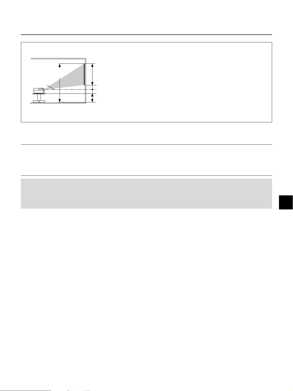
Installation Height of Projection Screen [Reference]
Once the installation location and position have been decided, the projection
height should be checked. In the case of large screen sizes, there are instances
where the image cannot be projected within the floor to ceiling height.
Screen size top edge dimension
measured from floor
Lens center
Screen size vertical
dimension
H dimension
7.2 cm(2.8 inch)
Stand dimension
The required installation height can be found using the following formula:
Screen size vertical cm(inch) + H cm(inch) + 7.2 cm(2.8 inch) + Stand height
Example: Using a 150" 4:3 screen and placing the projector horizontally, the required installation height will be
228.6 cm(90 inch) + 45.5 cm(17.9 inch) + 7.2 cm(2.8 inch) = 281.3 cm(110.7 inch)
(without a stand)
An installation room with a height of 240 cm(94.5 inch) will have insufficient room
height even when the projector is placed on the floor. (Note that the rear adjusters can be raised to lower the projection screen image.)
Note:
* Determine the screen size after checking the height and width of the room in which the screen will be installed as well as checking that there are no obstacles
located in the path between the lens and the screen.
* The larger the screen size becomes, the darker the image will be.
Placing the projector to the rear of the screen to project the image will require the use of a translucent type screen.
* The height from the feet of the main unit to the center of the lens is 7.2 cm (2.8inch).
* There is a tolerance of ±5% due to design values.
Attention!
• Do not install in location that will reach high or low temperatures. (Operation temperature: within 5°C (41°F) to 35°C (95°F))
•To raise the projection screen position, place the unit on a stable and strong support.
• Make efforts to ensure that sunlight or room illumination does not strike the screen. The more such extraneous light is
shielded, the higher the contrast and more attractive the image that will be obtained.
E – 15
Page 16
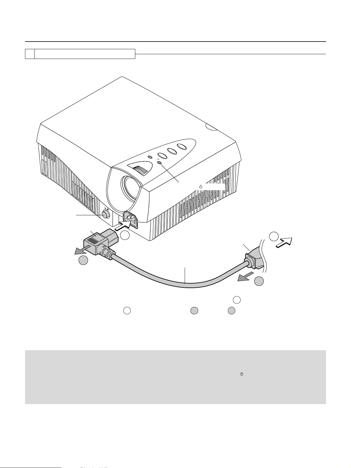
Power Cable Connections
2 Power Cable Connections
Use the supplied power cord to connect the power connector of the main unit with the power outlet.
E
C
R
U
O
S
T
C
E
P
S
A
Y
B
D
N
A
S
T
U
S
T
/
A
N
T
O
S
/
R
E
W
O
P
POWER/ indicator
POWER
ON OFF
POWER switch
Firmly insert all the way.
4
1
Firmly insert all the way.
Power cable (supplied)
To wall outlet
2
3
Before using the projector, first connect 1 and then
; after using, unplug 3 and then 4.
2
Attention!
For pluggable equipment, install the projector as near to the power outlet socket that is easily accessible.
Do not switch off the main power or disconnect the power cable unless the POWER/
could shorten the life of the lamp or possibly cause the unit to malfunction.
When the unit is set to off (and the LED is not lit) using the menu [Setup] → [LED] items, the indicator flashes green for 1
minute, then goes off. Likewise, at this time the main power should not be switched off and the power cord should not be
disconnected.
indicator is lit orange. Doing so
E – 16
Page 17

Connecting Video Equipment and Personal Computers
By connecting this unit with video equipment and using a DVD player or other source in combination with an audio/video amplifier
and speaker system will allow you to enjoy convincing home theater. Connecting the unit to a personal computer will permit
presentation data to be projected as a large screen display in conferences and lectures.
3 Connections with VIDEO and S-VIDEO Connectors
These are connections made with equipment that is equipped with a video output connector or an S-video output connector such
as video decks, DVD players, laser disc players, TV tuners, etc.
Connect such equipment to the VIDEO or S-VIDEO connector of this projector.
Connections with the S-VIDEO Output Connector
D
V
I-D
V
I
D
E
O
R
G
B
Y
P
b
/C
b
P
r
/
C
r
VIDEO
S
-
V
I
D
E
O
C
T
R
L
VIDEO
S-VIDEO
RGB
Connect to the
green jack.
Pr/Cr
S-VIDEO
Pb/Cb
Y
R
AUDIO
L
Connect to the output jack
marked S-VIDEO. Check
before inserting, since this
connector must be oriented
properly.
S-video cable (supplied)
Connections with the Video Output Connector
Connect to the yellow output
VIDEO
jack marked VIDEO.
Video cable (Commercially available)
VIDEO
R
AUDIO
L
Note:
* Connection can be made with the S1 video and S2 video output connectors,
but the control signals will not be operable in the projector depending on
video equipment.
* Please refer to the various manuals for information about video equipment
and audio/video amplifier and speaker system connections.
Attention!
Before making connections, check that the main power supply is switched off for the projector and the equipment that is
to be connected.
E – 17
Page 18

G
Connecting Video Equipment and Personal Computers
3 Connections with YCbCr/YPbPr Connectors
These are connections made with equipment such as DVD players that have YCbCr output connectors or YPbPr output connectors.
Make connections with the YPbPr/YCbCr connectors of this projector.
Component signal cable
(available as an option)
(order code: 27-062)
G
Make connections to the YPbPr output
jacks marked COMPONENT or
COLOR-DIFFERENCE SIGNAL.
BR
YPbPr
COMPONENT
G
BR
D
V
I
D
V
I
D
E
O
R
G
B
Y
P
b
/
C
b
P
r
/
C
r
VIDEO
S
-
V
ID
E
O
C
T
R
L
B
Y
G
Pb/Cb
BR
S-VIDEO
Pr/Cr
The YPbPr/YCbCr connectors and the
COMPONENT
YCbCr
G
BR
cables are color coded. Match the
same colors when making connections.
Component signal cable
(available as an option)
(order code: 27-062)
Make connections to the YCbCr
output jacks marked COMPONENT or
COLOR-DIFFERENCE SIGNAL.
Note:
* When inputting a YPbPr signal, format selection or color space selection
may be required. → page E-38
* Please refer to the various manuals for information about video equipment
and audio/video amplifier and speaker system connections.
E – 18
Page 19

Connecting Video Equipment and Personal Computers
3 Connection with RGB and DVI-D Connector
These connections are made with personal computers that have a monitor output RGB connector (analog signal) or a DVI-D
connector (digital signal). Connect personal computers having a mini D-Sub 15-pin RGB connector to the RGB connector of the
projector and connect personal computers having a DVI standard DVI-D connector to the DVI-D connector of the projector.
Check the following before making connections.
* The resolution through this unit is S-VGA 800 x 600 dots. VGA is enlarged and displayed and XGA is compressed and displayed.
Input of resolutions higher than S-XGA will not be displayed. Such resolutions should be converted to a displayable resolution at
the personal computer side. Check with the "Table of Supported Frequencies" on Page E-49.
* The setting method of the personal computer will vary depending on your personal computer. For information, read the instruc-
tion manual for your personal computer, read the on-line help, or contact the manufacturer of your personal computer.
RGB cable (Commercially available)
Plug in, then turn the screws
to secure.
D
V
I
D
V
I
D
E
O
R
G
B
Y
P
b
/
C
b
P
r
/
C
r
S
-
V
I
D
E
O
C
T
R
L
VIDEO
DVI-D RGB
Y
MONITOR OUTPUT
Connect with the monitor
output or the connector that
provides picture display.
MONITOR OUTPUT
DVI-D
DVI-D cable
(available as an option)
(
order code: 27-060
)
Note:
* This unit uses a digital interface 24-pin DVI-D connector. Digital signal TMDS (Transition Minimized Differential Signalling) of the DVI (Digital Visual Interface)
standard is used. (Analog RGB signals cannot be input.)
* Personal computers that are not equipped with a DVI-D connector require a digital graphics board furnished with a DVI-D connector.
* Before making connections, turn off the main power to the projector and all the connected equipment.
E – 19
Page 20

Connecting Video Equipment and Personal Computers
Obtaining an External Output Signal from a Notebook Computer.
When projection will be with a notebook computer connected, knowledge will be required for the cable connection and notebook
computer startup procedure as well as the operation that follows notebook startup. Please consult the instruction manual of your
notebook computer or the on-line help while performing the following procedure.
1 Check whether a signal is being sent from the notebook computer to the projector.
An indication appearing on the liquid crystal display of the notebook computer does not necessarily mean that an external output
signal is- being output.
Reference: When the frequency under [Info.] of the projector menu is displayed as 0 kHz, 0 Hz, it indicates that an external
output signal is not being output from the personal computer. → Page E-43 "Viewing the Lamp Timer/Resolution and Frequency"
2 Should a signal not be output from the notebook computer, please try the operation described
below.
For an IBM PC/AT, DOS/V computer, press the [Fn] key plus any one of the [F1] to [F12] keys. (See the table below.)
Manufacturer Model Key
akia All computers Fn + F2
COMPAQ ARMADA Series Fn + F4
PRESARIO Series Fn + F3
DELL All computers Fn + F8
FUJITSU All computers Fn + F10
GATEWAY All computers Fn + F3
IBM All computers Fn + F7
NEC All computers Fn + F3
Panasonic All computers Fn + F3
SHARP All computers Fn + F5
SONY All computers Fn + F7
SOTEC All computers Fn + F3
TOSHIBA All computers Fn + F5
Note: Table information is current to June 2001.
Note: When the liquid crystal display of the notebook computer and the projector are displayed at the same time, the projected image might not be correct even
though the liquid crystal screen shows a proper display. Should this occur, stop the simultaneous display of the notebook computer and try the mode with external
output only. (Try an operation such as that described in aforementioned Step 2 and try closing the liquid crystal panel which might result in external output only.)
E – 20
Page 21

Turning ON or OFF Main Power
POWER
ON OFF
STATUS
POWER
/
4 Turning ON or OFF Main Power
Before turning the main power, check that the power is switched off the equipment that is to
be connected and the connection is finished.
To turn on the main power:
Press the POWER switch down until it is in the depressed position.
Light in orange
ON/STANDBY button
POWER
ON OFF
POWER switch
E
C
R
U
O
S
T
C
E
P
S
A
Y
B
D
N
A
S
T
U
S
T
/
A
N
T
O
S
/
R
E
W
O
P
To turn off the main power:
Press the POWER switch until it is in the protruded position.
On condition
POWER
ON OFF
Off condition
Main power ON
Indicator OFF
POWER
STATUS
/
Main power OFF
POWER/ indicator
5 Turning ON or OFF Power
The ON/STANDBY buttons of the main unit and the remote control have the same function. A description using the main unit button
is provided here.
To turn on the power:
Press the ON/STANDBY button for about 2 seconds. The projection
screen will brighten in about 40 seconds.
Note: When the unit is set to off (and the LED is not lit) using the menu [Setup]
[LED] items, the indicator flashes green for 60 seconds, then goes off.
Setting standby mode
Press and hold down the ON/STANDBY button for about 2 seconds.
To s witch on the power again, leave at least 60 seconds before doing
so.
Light in orange
POWER
→
Light in green
POWER
/
ON
/
STANDBY
POWER
/
ON/STANDBY
STATUS
Flashing for 60 seconds
STATUS
Flashing green
POWER
STATUS
/
Flashing orange
POWER
STATUS
/
Flashing for 60 seconds
Light in green
POWER
/
Power ON
Light in orange
POWER
/
Standby
STATUS
STATUS
Attention!
• Do not switch off the main power or disconnect the power cable unless the POWER/
indicator is lit orange. Doing so
could shorten the life of the lamp or possibly cause the unit to malfunction.
When the unit is set to ON (and the LED is not lit) using the menu [Setup] → [LED] items, the indicator flashes green for
1 minute, then goes off. Likewise, at this time the main power should not be switched off.
•To save power, switch off the main power when not in use. When the main unit or remote control ON/STANDBY button is
used to set the projector to the standby mode (POWER/
Note:
* When a signal is not being input while projecting onto the projection screen, "No Signal" is displayed to indicate the condition. The background color of the screen
will be blue at this time. The background color can be changed to black by via [Setup] → [Background] of the menu. → Page E-40 "Background Color Settings"
* When the power is switched on, the input selection and aspect selection conditions will be the same as the conditions that existed when the power was switched
off.
* Adjustments and setting values that were made via menu operations will be stored even when the main power has been switched off or the power cord has been
disconnected.
When the power won't switch on
* When the internal temperature is abnormally high, the power will not be switched on to protect the equipment. Wait for a while and then try switching on the power
again.
* Should the STATUS indicator be lit or flashing, please see "When the STATUS Indicator Is Lit/Flashing" on Page E-45.
indicator is lit orange), the cooling fan continues to operate.
E – 21
Page 22

Adjustment of the Projection Screen
Operations include the adjustment of the image position that is projected to the screen and the adjustment of the focus as well as
the input selection and the selection of the aspect ratio.
Perform these operations with the power of the connected equipment switched on and the video signal input to the projector.
6 Projection Screen Position Adjustment
Adjust the projection image to the screen
(1) If the image is shifted to the left or right, move the main unit horizontally. (Align the center of the screen and the center of
1
the lens of the main unit.)
(2) If the image is shifted vertically, move the image up or down with the adjuster.
(3) A projection image such as that illustrated in the diagram is the result of the projector not being perpendicular to the
screen. Set the projector so that it is pointing straight toward the screen.
(4) If the image shows keystone distortion, adjust using menu operations. → Page E-39 "Adjustment of Keystone Distortion"
(2)
(4)
(1)
(3)
Using the Adjusters
To lower the projection position:
Raise the rear adjusters up
7 Adjustment of Screen Size and Focus
Turn the zoom ring and adjust the screen
size, then turn the focus ring and adjust the
2
focus.
FOCUS ring
To raise the projection position:
Attach the supplied two adjusters to the front feet. See page
E-9 "Attaching the Supplied Adjusters".
After folding the rear adjusters, rotate the right/left front adjuster to fine-adjust the height. (Adjustable range: 0 to 5 mm/
0 to 0.2 inch)
T
C
Note: The zoom ring allows adjustment of approxi-
E
P
S
Y
B
D
S
U
T
N
A
T
S
/
R
E
W
O
P
A
A
T
S
/
N
O
ZOOM ring
mately 20% of the maximum screen size. (When the
zoom ring is at the center position, an adjustment of
approximately ±10% will be possible.)
E – 22
Page 23

8 Input Selection
Adjustment of the Projection Screen
Press the SOURCE button and select
the desired connector.
3
SOURCE
Input display
S-VIDEO
A press of the SOURCE button will display the
selected input.
Each press of the button moves the selection
one step in the sequence:
S-VIDEO → (VIDEO/YCbCr/YPbPr) → RGB
→ DVI
The selection will not change while "Now Searching" is displayed.
The input display will remain for a while before
disappearing. To change the duration of the display, see → Page E-41 "On-Screen Display Du-
DVI
RGB
S-VIDEO
VIDEO
YCbCr
YPbPr
ration Setting."
9 Selection of Aspect Ratio (i.e., Ratio of Screen Width to Screen Height)
Press the ASPECT button and select
the desired aspect ratio.
4
ASPECT
A press of the button will display the aspect selection display.
The aspect ratio is the ratio of the width and height
of the screen.
Aspect Selection Display
Full
16:9(LB)
16:9
Real
Thru
S-VIDEO
Aspect
Note:
* The remote control provides direct selec-
tion from the VIDEO button, S-VIDEO button, YCbCr button, and DVI button.
* When a function other than [AUTO] is
specified at the source selection display,
the projector searches for the specified
signal among VIDEO/YCbCR/YPbPr.
Page E-23 "Input Selection"
* When a signal is not input to the selected
connector, "No Signal" is displayed.
* When RGB or DVI is selected and "No Sig-
nal" is displayed, check with [Info.] on the
menu.
→
Page E-43 "Viewing the Lamp Timer/
Resolution and Frequency"
When the frequency is displayed as "0 kHz,
0 Hz," there is no signal from the personal
computer. → See Page E-20 "Obtaining
an External Output Signal from a Notebook Computer."
Note:
* The aspect ratio selection display will not
appear unless a signal is input. Play the
video of the equipment.
* Match the aspect ratio of the image of the
connected equipment with the aspect ratio of the projected image of this unit, or
adjust the image of a 16:9 aspect to the
desired format.
* When the aspect ratio differs, a circle, for
example, will be projected as an ellipse.
* The selected aspect ratio for each input is
stored.
→
[VIDEO, S-VIDEO, YCbCr and YPbPr Input Selection]
Aspect
Full
16:9(LB)
16:9
Real
Thru
S-VIDEO
[RGB and DVI Input Selection]
Aspect
Full
Auto
16:9
Thru
Cursor: Displays the currently selected
contents position.
Press the ASPECT button during the appearance of the aspect selection display and
make the selection.
Each press of the button moves the cursor and switches the aspect ratio.
A diagram of the a sample image with different aspect ratios is carried on the next page.
The aspect selection display will remain for a while before disappearing.
To change the duration of the display, see → Page E-41 "On-Screen Display Duration
Setting."
This completes the projection screen adjustments.
DVI
Note:
* For information about operation with the
remote control, see → Page E-25 "Operation with the Remote Control"
*To adjust or set the brightness, picture,
or other matters, display the menu on the
projection screen and perform the operation. → Page E-28 "Using the On-Screen
Menu"
E – 23
Page 24

Adjustment of the Projection Screen
Input Screen and Aspect Ratio Selection Screen
Select Full
The image is projected to fill the entire
screen.
Aspect 16:9 screens will be longer than wide.
Select Auto
(only with RGB or DVI selection)
While maintaining the aspect ratio of the personal computer, the image is enlarged or
reduced so that no parts protrude beyond
the screen and the image is projected to fill
the screen. Aspect 16:9 screens will be black
at the top and bottom.
Select 16:9 (LB)
(S-VIDEO, VIDEO, YCbCr, and YPbPr only)
The image of long sideways movie material
is projected to fill the entire screen without
the top and bottom black portions.
This maintains a letterbox image aspect ratio and
projects it on a 16:9 screen.
This will make the image quality better than "Full".
Projection image with
Through selection
"XXXXX••••••"
Projection image when
selected
The top and bottom
black portions are cut.
Subtitles are also cut.
Select 16:9
This returns the squeezed screen to a 16:9
The output size becomes 848 x 480.
screen and projects it.
The output size becomes 848 x 480.
Select Real
(S-VIDEO, VIDEO, YCbCr and YPbPr only)
This maintains a video image aspect ratio
of 4:3 and projects it.
Images with a 16:9 aspect ratio will become
vertically elongated (4:3).
Select Thru
This projects the input image as is. When the input resolution is higher than that of the projector (800 x 600), the image will extend
beyond the screen, and when lower, the image will be smaller than the screen. Video images may have a different aspect ratio.
[Display Examples]
E – 24
Video signal
Squeeze signal VGA 640 x 480
16:9 screen
Letter box
Page 25

Operation with the Remote Control
Point the remote control toward the remote control sensor of the main unit and operate.
ASPECT button
This button selects the vertical and horizontal
ratio of the screen of the input video.
ON/STANDBY button
This button is used to switch ON the power and set the unit
to the STANDBY mode.
ASPECT
ON/STANDBY
These buttons are used for the
S
selection of the input signal.
VIDEO
-
VIDEO
/YPbPr
SV CV RGB DV I
For further information about input selection.
S-VIDEO button
This switches the input to the S-VIDEO signal.
VIDEO/YPbPr button
The source selection display will appear.
RGB button
SET
This switches the input to the RGB signal.
DVI button
This switches the input to the DVI-D signal.
This is used for selection of VIDEO, YCbCr, and
YPbPr input signals.
Tur ning ON Power/STANDBY
Press the POWER button of the main unit and turn on the main
power.
To turn on the power:
Check that the POWER/ indicator of the main unit is lit orange.
RGB
DVI
MENU
ESC
SET button
Automatic adjustment of the RGB input signal is performed
when the menu is closed and the SET button is held down
for more than 1 second.
These buttons are used for menu operations.
→
Page E-28 "Using the On-Screen Menu"
MENU button
This is used in the selection of the menu name when
displaying the menu on the projection screen.
ESC button
This is used when closing the menu.
SET button
This is used to set the menu items.
Cursor buttons (왗 왘왖왔)
These are used in the selection of the menu name, item
name, and contents.
Press the ON/STANDBY button for about 2 seconds.
ON/STANDBY
The power will be switched on, the indicator will flash green (for
Light in green
POWER
/
Power ON
STATUS
Note: To save electrical power when not
using the unit, switch off the main power.
When doing so, wait until the flashing
orange indicator is lit steadily.
one minute) and then the indicator will be lit green. The projection screen will brighten in about 40 seconds.
Setting standby mode:
Light in orange
Press and hold down the ON/STANDBY button for about 2 seconds.
The indicator will flash orange (for 60 seconds) and then be lit
orange.
POWER
/
Standby
STATUS
Attention!
When switching off the main power or disconnecting the power cable
First press ON/STANDBY button of the remote control or the main unit to set the standby mode (in which the indicator will
be lit orange) and then switch off the main power. If the main power of the main unit is switched off without setting the
standby mode, this could shorten the life of the lamp or possibly cause damage due to the heat of the lamp.
E – 25
Page 26

Operation with the Remote Control
Input Selection
Press the desired input selection button.
-
VIDEO
S
VIDEO
/YPbPr
RGB
SV CV RGB DVI
S-VIDEO button
A press of the button will switch the input to the S-VIDEO
input signal.
VIDEO/YPbPr button
The source selection display will appear. (If the source
selection display is not displayed, press the button again.)
*[AUTO] is selected at the initial setting.
A press of the SET button causes the source selection
display to disappear and starts an automatic search of
the VIDEO/YCbCr/YPbPr input signal.
* The input display at the [AUTO] setting will be
[Video/YCbCr/YPbPr].
RGB button
A press of this button switches the unit to the RGB input
signal.
DVI button
A press of this button switches the unit to the DVI input
signal.
DVI
Input selection display
S-VIDEO
DVI
RGB
S-VIDEO
VIDEO
YCbCr
YPbPr
Note:
* When the power is switched on, the input
selection conditions that existed when the
power was switched off will be in effect.
* When a signal is not input to the selected
connector, "No Signal" is displayed.
* When RGB or DVI is selected and "No Sig-
nal" is displayed, check with [Info.] on the
menu.
→
Page E-43 "Viewing the Lamp Timer/
Resolution and Frequency"
When the frequency is displayed as "0 kHz,
0 Hz," there is no signal from the personal
computer. → See Page E-20 "Obtaining an
External Output Signal from a Notebook
Computer."
The input display will remain on for a while before disappearing. To change the duration of the display, see → Page
E-41 "On-Screen Display Duration Setting."
VIDEO/YCbCr/YPbPr Signal Selection
The input signal is specified directly and projected.
A press of the VIDEO/YPbPr button displays the source
selection display. (If the source selection display is not
displayed, press the button again.)
Select the signal with the cursor (왖왔) button or the
VIDEO/YPbPr button.
A press of the SET button causes the source selection
display to disappear, performs a search for the specified
signal and projects it.
Source selection display
SOURCE
AUTO
VIDEO
YCbCr
YPbPr
SOURCE
AUTO
VIDEO
YCbCr
YPbPr
Note:
* When the source selection is specified as
[AUTO], upon switching to the VIDEO/
YCbCr/YPbPr signal, a search for the signals will be made in order and it may take
a while before the signal is displayed. The
signal can be projected quickly when it has
been specified directly.
* Conversely, for example, when connection
is made to a video system that switches
the input signal from a YCbCr signal to a
YPbPr signal, having previously set the
source selection to [AUTO], another press
of the VIDEO/YPbPr button (i.e., the
SOURCE button on the projector) will perform automatic identification of the signal.
E – 26
Page 27

Selection of Aspect Ratio (i.e., Ratio of Screen Width to Screen Height)
Operation with the Remote Control
Press the ASPECT button and select the
Aspect Selection Display
desired aspect ratio.
ASPECT
Aspect
A press of the button will display the aspect selection
display.
The aspect ratio is the ratio of the width and height of the
screen.
[VIDEO, S-VIDEO, YCbCr and YPbPr Input Selection]
Aspect
S-VIDEO
Full
16:9(LB)
16:9
Real
Thru
[RGB, DVI Input Selection]
Aspect
Full
Auto
16:9
Thru
Cursor: Displays the currently selected
contents position.
Press the ASPECT button while the aspect selection display is shown and make the selection.
Each press of the button moves the cursor and switches the aspect ratio.
Also the selection can be made with the cursor (왖왔) buttons.
Full
16:9(LB)
16:9
Real
Thru
S-VIDEO
DVI
Note:
* The aspect ratio selection display will not
appear unless a signal is input. Play the
video of the equipment.
* Match the aspect ratio of the image of the
connected equipment with the aspect ratio
of the projected image of this unit, or adjust the image of a 16:9 aspect to the desired format.
* When the aspect ratio differs, a circle, for
example, will be projected as an ellipse.
* The selected aspect ratio for each input is
stored.
A diagram of the a sample image with different aspect ratios is carried on the next page.
The aspect selection display will remain for a while before disappearing.
To change the duration of the display, see → Page E-41 "On-Screen Display Duration Setting."
Automatic Adjustment of the Input Signal
This automatically adjusts the projected RGB signal to an optimum condition.
Only the RGB, DVI and YPbPr (480p) signals can
be automatically adjusted.
SET
Holding down the SET button for more than 1 second starts
the automatic adjustment.
During the adjustment, [AUTO] is display at the center of the
screen.
When the menu is displayed, the button that is associated with
the menu item will be operational; therefore, press the ESC
button to close the menu before making this adjustment.
Note:
* This automatically adjusts the stripe pat-
terns, color infidelity, and flicker which arise
from pixel shift.
When proper adjustment cannot be obtained with automatic adjustment upon
pressing the SET button, please adjust
manually.
See E-35 "Adjusting the Clock Frequency
of the Input Signal" and "Adjusting the
Phase of the Input Signal".
E – 27
Page 28

Using the On-Screen Menu
Picture1
Language En De Fr It Es
- Menu Position Duration 10 sec.
Picture2 Setup Info.
VIDEO
Option
Only menu operation methods will be described here.
Refer to this page should you need to clarify matters during menu operations.
See the various pages for information about menu functions and performing adjustments and settings.
To perform adjustments and settings, the video is projected and adjustments are made to the optimum condition.
The remote control should be pointed toward the remote control sensor of the projector and operated.
To return the various items that have been changed with the menu to their default values (i.e., the condition that existed at the time
of purchase), see → Page E-43 "Returning to Standard Settings."
Names and functions of the buttons
used in menu operations
ASPECT
VIDEO
-
VIDEO
S
/YPbPr
SV CV RGB DVI
SET
ON/STANDBY
RGB
DVI
MENU
ESC
MENU button
Used to display menus and in selection of
menu names.
ESC button
Used to close the menu.
SET button
Used to set the menu item.
Names and functions of the menu screens
Menu names
These are the menu headings. When a menu is selected, there
is a switch to the heading screen. The selected menu name
appears in blue.
Input selection display
This is the currently
selected input signal
screen.
[Setting Screen Display Example]
Selected contents
Select the desired contents. Selected
characters appear in red.
Item name
This is the name of the adjustment or setting.
The selected item name appears in navy blue.
A press of the SET button at a location where only
the item name is displayed results in a change to the
selection contents screen.
The contents will change for the item name
depending on the input selection.
E – 28
Cursor buttons (왗 왘왖왔)
These are used in menu name selection and
in the contents selection.
Cursor
The item at the cursor position can be adjusted or set.
Move the cursor with the cursor buttons.
Note:
* If a remote control operation is not performed in about
10 seconds (i.e., the initial setting time) from the time the
menu is displayed, the menu will automatically close.
→
Page E-41 "On-Screen Display Duration Setting"
* The display position of the menu can be changed.
→
Page E-41 "Moving the Menu Display Position"
Page 29

Display of the Menu
Press the MENU button and display
the menu.
1
MENU
Selection of the Menu Name
Press the button again and select the
menu name.
2
The selected menu name will appear in navy
blue.
Picture1
Keystone Mode Normal Full
- Installation Background
Auto Power Off
LED
Picture2 Setup Info.
+0Keystone
Option
Blue Black
Off On
Off On
VIDEO
Picture1
Picture2 Setup Info.
Brightness 0
Contrast 0
Color 0
Tint 0
Sharpness 0
Color Temp. Low Normal High Custom
MENU
Each press of the MENU button switches
the menu one step in the sequence of
[Picture 1] → [Picture 2] → [Setup] →
[Option] → [Info.]
Option
VIDEO
Using the On-Screen Menu
Note:
* The menu name will change also
when the cursor (왗왘) button is
pressed.
* When using the cursor button to se-
lect the menu name, the cursor must
be in the menu name column (at the
very top) or else selection will not
be possible.
* When the cursor is not located at the
menu name, the selected menu
name will appear in blue.
* For information about the contents
list that is displayed in the menu, see
→
Page E-31 "Menu List."
Selection of the Item Name
Press the cursor button (왖왔) and select the item name.
3
Align the cursor with the desired item name. The
selected item name will appear in deep blue.
VIDEO
Picture1
Keystone Mode Normal Full
- Installation Background
Auto Power Off
LED
Picture2 Setup Info.
+0Keystone
Option
Blue Black
Off On
Off On
Making Adjustments and Settings
Press the cursor button (왗왘) and
make the adjustment (or selection).
4
Adjust (or select) to produce the best picture.
[Adjustment Item Examples]
Picture1
Keystone Mode Normal Full
- Installation Background
Auto Power Off
LED
Picture2 Setup Info.
+0Keystone
Option
Blue Black
Off On
Off On
VIDEO
SET
SET
Note: When the cursor is not located
at the menu name, the selected menu
name will appear in blue.
Note:
* For adjustment items, adjustment
values are indicated by the increase
and decrease of the adjustment bar
and the numerical value.
Adjust for the optimum picture while
viewing the image projected to the
screen.
* The selected characters will appear
in red for items that select On, Off,
and other titles.
(Continued on the next page)
Adjustment bar
E – 29
Page 30

Using the On-Screen Menu
Sub menu items
Items that display only an item name have a
sub menu.
VIDEO
Picture1
Keystone Mode Normal Full
- Installation -
Background
Auto Power Off
LED
Picture1
Keystone Mode
Keystone
- Installation -
Background
Auto Power Off
LED
Picture2 Setup Info.
+0Keystone
Picture2 Setup Info.
Option
Blue Black
Off On
Off On
Floor-Front
Option
Floor-Rear
Ceiling-Front
Ceiling-Rear
VIDEO
1) Press the SET button to display
the sub menu.
SET
2) For setup, select with the cursor
button (왖왔).
SET
Note: The selection operation will differ for the sub menu depending on the
item contents.
Note: A transition to item selection of
the menu will not be possible while the
sub menu is being displayed. To select
the next item, press the ESC button,
close the menu again, then perform the
selection.
Picture1
Keystone Mode Normal Full
- Installation -
Background
Auto Power Off
LED
Picture2 Setup Info.
+0Keystone
Option
Blue Black
Off On
Off On
Exit
Press the ESC button and close the
menu display.
5
The selected menu name will appear in navy
blue.
ESC
VIDEO
3) Press the SET button to finalize.
The sub menu will close.
SET
Note:
* Even without pressing the ESC but-
ton, waiting a while will result in the
menu closing (when the display duration setting has elapsed).
* The adjustment and setting values
will be stored even when the power
is switched off or the power cord is
disconnected.
E – 30
Page 31

Menu List
Various inputs allowed
VIDEO, S-VIDEO, and YCbCr
This is a list of menu item names. See the reference page for information about the adjustment and setting
method.
The display contents of the item name will differ depending on the input selection.
Indications such as those below appear along side the input selections (i.e., input signals) that permit adjustment or setting.
Adjustment or setting is permitted for any input that is selected. (The item name will appear in the menu.)
Adjustment or setting is permitted only when the "VIDEO, S-VIDEO, and YCbCr" indication appears at the
time of the listed input selection. (In this case, the item name will be displayed only when a VIDEO, S-VIDEO,
or YCbCr signal is input.
Picture 1
"Adjusting the Brightness" → Page E-33
"Adjusting the Contrast" → Page E-33
"Adjusting the color" → Page E-33
"Adjusting the tint" → Page E-34
"Adjusting the Sharpness" → Page E-34
"Adjusting the White Balance" → Page E-34
[VIDEO and S-VIDEO Input Selection]
Picture1
Brightness 0
Contrast 0
Color 0
Tint 0
Sharpness 2
Color Temp. Low Normal High Custom
Picture2 Setup Info.
Option
VIDEO
"Adjusting the Clock Frequency of the Input Signal"
→ Page E-35
"Adjusting the Phase of the Input Signal" → Page E-35
Picture 2
"Adjusting the Sharpness of the Video Image"
"Adjusting the Sharpness When Expanding/Compressing"
"ProScan Mode Settings" → Page E-36
"Gamma Settings" → Page E-37
"Video Signal Color System Settings" → Page E-38
→ Page E-36
→ Page E-36
[YCbCr Input Selection]
Picture1
Brightness 0
Contrast 0
Color 0
Sharpness 2
Color Temp. Low Normal High Custom
[YPbPr Input Selection]
Picture1
Brightness 0
Contrast 0
Tint 0
Clock frequency 0
Phase 0
Color Temp. Low Normal High Custom
[RGB and YPbPr Input Selection]
Picture1
Brightness 0
Contrast 0
Clock frequency 0
Phase 0
Color Temp. Low Normal High Custom
[DVI Input Selection]
Picture1
Brightness 0
Contrast 0
Color Temp. Low Normal High Custom
[VIDEO, S-VIDEO, and YCbCr Input Selection]
Picture1
Video Filter 2
Gamma CustomGraphicsFilmVideo
Color System Auto
Picture2 Setup Info.
Picture2 Setup Info.
Picture2 Setup Info.
Picture2 Setup Info.
Picture2 Setup Info.
3Zoom Filter
Option
Option
Option
Option
VIDEO
Option
Video AutoProScan Mode
YCbCr
YPbPr
RGB
DVI
E – 31
Page 32

Menu List
"Format Settings" → Page E-38
"Color Space Settings" → Page E-38
"Movement of Screen Display Position" → Page E-37
"Setting of White Emphasis" → Page E-38
Setup
"Adjustment of Keystone Distortion" → Page E-39
"Screen Projection System Settings" → Page E-39
"Background Color Settings" → Page E-40
"Auto Standby Settings" → Page E-40
"LED Display Settings" → Page E-40
[YPbPr Input Selection]
Picture1
Zoom Filter 3
- Pan Gamma
Format
Color Space
[RGB and DVI Input Selection]
Picture1
Zoom Filter 3
- Pan Gamma CustomGraphicsFilmVideo
White Peak
[Common Inputs]
Picture1
Keystone Mode Normal Full
- Installation Background
Auto Power Off
LED
Picture2 Setup Info.
Auto
Auto
Picture2 Setup Info.
Picture2 Setup Info.
+0Keystone
Option
Option
Off On
Option
Blue Black
Off On
Off On
YPbPr
CustomGraphicsFilmVideo
RGB
VIDEO
Option
"On-Screen Display Language Settings" → Page E-41
"Moving the Menu Display Position" → Page E-41
"On-Screen Display Duration Adjustment" → Page E-41
Info.
"Saving and Loading of Video Adjustments" → Page E-42
"Returning to Standard Settings" → Page E-43
"Resetting the Lamp Timer" → Page E-43
"Viewing the Lamp Timer/Resolution and Frequency"
→ Page E-43
[Common Inputs]
Picture1
Language En De Fr It Es
- Menu Position Duration 10 sec.
[VIDEO, S-VIDEO and YCbCr Input Selection]
Picture1
User Memory Save Load
- Default -
- Lamp Timer Reset -
--------------------------- Status: 100 . 500
Lamp Timer: 1 hrs (Total 1 hrs)
[RGB and DVI Input Selection]
Picture1
- Default -
- Lamp Timer Reset -
--------------------------- Status: 100 . 500
Resolution:
Frequency:
Lamp Timer: 1 hrs (Total 1 hrs)
Picture2 Setup Info.
Picture2 Setup Info.
Picture2 Setup Info.Option
800 X 600
H: 37.8KHz V: 60Hz
Option
Option
VIDEO
VIDEO
DVI
E – 32
Page 33

Video Adjustments [Picture 1]
Various inputs allowed
Various inputs allowed
VIDEO, S-VIDEO and YCbCr
These are picture-related adjustments.
For information about performing menu operations, see → Page E-28
"Using the On-Screen Menus."
[YCbCr Input Selection] [RGB Input Selection]
Picture2 Setup Info.
Picture1
Brightness 0
Contrast 0
Color 0
Sharpness 2
Color Temp. Low Normal High Custom
Option
YCbCr
[YPbPr Input Selection]
Picture2 Setup Info.
Picture1
Brightness 0
Contrast 0
Tint 0
Clock frequency 0
Phase 0
Color Temp. Low Normal High Custom
Option
YPbPr
Preparation
* Project the image.
* Press the MENU button to display the menu, then select [Picture 1].
[VIDEO and S-VIDEO Input Selection]
Picture2 Setup Info.
Picture1
Brightness 0
Contrast 0
Color 0
Tint 0
Sharpness 2
Color Temp. Low Normal High Custom
Picture2 Setup Info.
Picture1
Brightness 0
Contrast 0
Clock frequency 0
Phase 0
Color Temp. Low Normal High Custom
[DVI Input Selection]
Picture2 Setup Info.
Picture1
Brightness 0
Contrast 0
Color Temp. Low Normal High Custom
Brightness
Adjusting the Brightness
The brightness of the image will differ depending on whether the room is bright or dark. Make
adjustments to suit your preference.
Press the cursor button (왖왔) and align the cursor with "Brightness", then adjust with the cursor (왗왘) button.
Picture1
Brightness 0
Contrast 0
Color 0
Tint 0
Sharpness 1
Color Temp. Low Normal High Custom
Picture2 Setup Info.
Option
VIDEO
Note: The adjustment values of the image can be stored and called according
to the various inputs.
→
Page E-42 "Saving and Loading of
Video Adjustments"
Option
VIDEO
RGB
Option
DVI
Option
Cursor (왗) Button: Darker
Cursor (왘) Button: Brighter
Contrast
Adjusting the Contrast
This is used in the adjustment of powerful images and natural images.
Press the cursor button (왖왔) and align the cursor with "Contrast", then adjust with the cursor
(왗왘) button.
Cursor (왗) Button: Less dense picture
Cursor (왘) Button: Denser picture
Color
Adjusting the color
This is used in the adjustment of powerful colors and natural colors.
Press the cursor button (왖왔) and align the cursor with "Color", then adjust with the cursor
(왗왘) button.
VIDEO
Picture1
Brightness 0
Color 0
Tint 0
Sharpness 1
Color Temp. Low Normal High Custom
Picture1
Brightness 0
Contrast 0
Color
Tint 0
Sharpness 1
Color Temp. Low Normal High Custom
Picture2 Setup Info.
0Contrast
Picture2 Setup Info.
0
Option
VIDEO
Option
Cursor (왗) Button: Lighter color
Cursor (왘) Button: Deeper color
E – 33
Page 34

Video Adjustments [Picture 1]
Various inputs allowed
VIDEO, S-VIDEO and YCbCr
VIDEO, S-VIDEO and YPbPr
Tint
Adjusting the tint
This is used in the adjustment of skin tones,
etc.
Press the cursor button (왖왔) and align the cursor with "Tint", then adjust with the cursor (왗왘)
button.
Cursor (왗) Button: Heightened red
Cursor (왘) Button: Heightened green
Sharpness
Adjusting the Sharpness
This is used in the adjustment of picture sharpness.
Press the cursor button (왖왔) and align the cursor with "Sharpness", then adjust with the cursor (왗왘) button.
Cursor (왗) Button: Softer picture
Cursor (왘) Button: More distinct picture
Color Temperature
VIDEO
Picture1
Brightness 0
Contrast 0
Color 0
Tint 0
Sharpness 1
Color Temp. Low Normal High Custom
Picture1
Brightness 0
Contrast 0
Color 0
Tint 0
Sharpness 1
Color Temp. Low Normal High Custom
Picture2 Setup Info.
0
Picture2 Setup Info.
Option
VIDEO
Option
Note: Adjustment is not possible with
PAL, SECAM video input.
Adjusting the White Balance
This is the input picture white color selection
or white and black level correction, and serves
to adjust the color reproducibility.
Press the cursor button (왖왔) and align the cursor with the desired item, then adjust with the
cursor (왗왘) button.
Low: Warm white (White with heightened yellow)
Normal: The white of sunlight
High: Cool white (White with heightened blue)
Custom adjustments
Press the (왗왘) cursor button and align the
cursor with [Custom], then press the SET
button.
The custom adjustment screen will appear.
Press the (왖왔) cursor button to select the
color, then adjust with the cursor (왗왘) button.
Adjust each of the red, green, and blue brightness levels.
After the adjustment, press the SET button to
finalize.
VIDEO
Picture1
Brightness 0
Contrast 0
Color 0
Tint 0
Sharpness 1
Color Temp. Low Normal High Custom
Picture2 Setup Info.
Option
[Custom Adjustment Screen]
Red
Picture1
Brightness
Contrast
Color
Tint
Sharpness
Color Temp. Low Normal High Custom
Picture2 Setup Info.
Green
Blue
0
Option
0
0
VIDEO
Note: Color temperature (or white balance) refers to the white color that becomes the reference of color representation. White color is expressed by the
mixture of red, green, and blue light. The
color temperature adjustment serves to
adjust the proportions of this mixture.
The color representation on the screen
will change depending on the environment including room illumination.
E – 34
Page 35

Clock frequency
RGB and YPbPr
RGB and YPbPr
Video Adjustments [Picture 1]
Adjusting the Clock Frequency of
the Input Signal
This is adjusted when light and dark vertical
bands appear on the projection screen of the
RGB and YPbPr input signal.
This is usually adjusted automatically at the
time of signal selection; however, this adjustment is made when the automatic adjustment
cannot effectively make the adjustment.
Press the cursor (왖왔) buttons and align the cursor with [Clock frequency], then use the cursor
buttons (왗왘) to remove the vertical bands and
render the screen brightness uniform.
Phase
Adjusting the Phase of the Input
Signal
This is adjusted when a color shift or flickering
appears on the projection screen of the RGB
or YPbPr input signal.
This is usually adjusted automatically at the
time of signal selection; however, this adjustment is made when the automatic adjustment
cannot effectively make the adjustment.
RGB
Picture1
Brightness 0
Contrast 0
Clock Frequency 0
Phase 0
Color Temp. Low Normal High Custom
Picture1
Brightness 0
Contrast 0
Clock Frequency 0
Phase 0
Color Temp. Low Normal High Custom
Picture2 Setup Info.
Picture2 Setup Info.
Option
RGB
Option
Note:
*A light and dark striped pattern will
appear when there is lack of correspondence between the input signal
and the pixel position of the projector. This is adjusted by the adjustment of the clock frequency.
* When the image extends beyond the
screen or is smaller than the screen,
check whether the [Aspect] setting
is set to "Full."
27 "Selection of Aspect Ratio (i.e.,
Ratio of Screen Width to Screen
Height)
→
Pages E-23 and E-
Press the cursor (왖왔) buttons and align the cursor with [Phase], then use the cursor buttons
(왗왘) to make the color shift or flickering incon-
spicuous.
E – 35
Page 36

Input Video Adjustments [Picture 2]
Various inputs allowed
VIDEO, S-VIDEO and YCbCr
VIDEO, S-VIDEO and YCbCr
These functions adjust the input video signal.
See → Page E-28 "Using the On-Screen Menu" for information about performing
menu operations.
[VIDEO, S-VIDEO, and YCbCr Input Selection]
Picture1
Video Filter 2
Gamma CustomGraphicsFilmVideo
Color System Auto
Picture2 Setup Info.
3Zoom Filter
Option
Video AutoProScan Mode
VIDEO
[YPbPr Input Selection] [RGB and DVI Input Selection]
Picture2 Setup Info.
Picture1
Zoom Filter 3
- Pan Gamma CustomGraphicsFilmVideo
Format
Color Space
Auto
Auto
Preparation
* Project an image.
* Press the MENU button to display the menu, then select [Picture 2].
Video Filter
Adjusting the Sharpness of the Video
Image
This adjustment is used to reduce the roughness and
provide a clear picture.
Press the cursor button (왖왔) and align the cursor with
the desired item, then adjust with the cursor (왗왘) but-
ton.
Adjust to your preference while viewing the picture.
Adjustment can be made from 0 to level 4.
Picture1
Video Filter 2
Gamma CustomGraphicsFilmVideo
Color System Auto
Picture2 Setup Info.
Zoom Filter
Option
2Zoom Filter
YPbPr
Video AutoProScan Mode
Option
Picture1
Picture2 Setup Info.
Zoom Filter 3
- Pan Gamma CustomGraphicsFilmVideo
White Peak
VIDEO
Note: The higher the level, the
more proper it is for high resolution.
Option
RGB
Off On
Adjusting the Sharpness When Expanding/Compressing
This adjusts the sharpness of the picture at the time
of pixel conversion in the selection of the aspect ratio.
Press the cursor button (왖왔) and align the cursor with
the desired item, then adjust with the cursor (왗왘) but-
ton.
Adjust to your preference while viewing the picture.
Adjustment can be made from 0 (OFF) to level 4.
ProScan Mode
ProScan Mode Settings
Set this according to the movie material.
Press the cursor button (왖왔) and align the cursor with
the [ProScan Mode], then select with the (왗왘) button.
Video: This setting progressive an input signal on the as-
sumption that it is a normal interlaced signal.
Auto: This setting automatically determines whether an
input signal is the movie material(24 frames) or the video
material (normal interlaced signal) to use progressive
scanning.
Picture1
Video Filter 2
Gamma CustomGraphicsFilmVideo
Color System Auto
Picture1
Video Filter 2
Gamma CustomGraphicsFilmVideo
Color System Auto
Picture2 Setup Info.
2Zoom Filter
Picture2 Setup Info.
2Zoom Filter
VIDEO
Option
Note: The greater the number of
adjustment level becomes, the
sharper an image is. The closer to
Video AutoProScan Mode
VIDEO
Option
Video AutoProScan Mode
0 the number of adjustment level
becomes, the softer an image is.
E – 36
Page 37

Pan
YPbPr, RGB and DVI
Various inputs allowed
Input Video Adjustments [Picture 2]
Movement of Screen Display Position
This is used to move the screen position at the time of
RGB, DVI and YPbPr input selection.
Press the cursor button (왖왔) and align the cursor with
[Pan], then press the SET button. The menu display will
close and the cursor display will appear.
Adjust the screen position horizontally with the cursor
(왗왘) button and vertically with the cursor (왖왔) button.
Gamma
Gamma Settings
These are settings of the tone of the image.
Press the cursor (왖왔) button and align the cursor with
[Gamma], then select with the cursor (왗왘) button.
Video: This is a gamma adjustment value suited to video
signals.
Film: This is a gamma adjustment value suited to movies.
Graphics: This is a gamma adjustment value suited to
graphics such as computer images.
Picture1
Zoom Filter 3
- Pan Gamma CustomGraphicsFilmVideo
White Peak
Picture1
Video Filter 2
Gamma CustomGraphicsFilmVideo
Color System Auto
Picture2 Setup Info.
SET
Picture2 Setup Info.
2Zoom Filter
Option
Off On
Option
Video AutoProScan Mode
RGB
Position
VIDEO
Note:
The display position can only be
moved when a large picture with a
resolution of 800 x 600 or greater
is displayed in the through mode.
Custom adjustments
This adjustment permits the creation of a desired
gamma curve.
This is performed while viewing the target image.
Select [Custom] with the cursor (왗왘) button, then
press the SET button.
The custom adjustment screen will be displayed.
1. Press the cursor (왖) button and align the cursor with
the index.
2. Select the adjustment point with the cursor (왗왘) but-
ton.
3. Select the color that is to be adjusted with the cursor
(왖왔) button, then adjust with the cursor (왗왘) but-
ton.
When required, adjust other adjustment points in the
same manner.
4. Press the SET button to finalize.
The custom adjustment screen will close.
Index
Red
Picture1
Video Filter
Zoom Filter
ProScan Mode
Gamma CustomGraphicsFilmVideo
Color System
Picture2 Setup Info.
Green
Blue
1
7
Option
7
7
VIDEO
Note: See → Page E-43 "Return-
ing to Standard Settings" for information about returning to the standard setting values. Note that other
adjustments and settings will also
be reset.
Note: Index (1 to 31) indicates adjustment point of a 32nd part of
input values between 0 and 255.
E – 37
Page 38

Input Video Adjustments [Picture 2]
VIDEO, S-VIDEO and YCbCr
YPbPr
YPbPr
RGB and DVI
Color System
Video Signal Color System Settings
These settings are of the color system of the composite video signal.
This function is normally set to Auto. If the color system cannot be identified on Auto, set it manually.
Press the (왖왔) cursor button and align the cursor with
[Color System], then press the SET button.
The color system selection display will appear.
Press the cursor (왖왔) button to match the composite
video signal system of the input equipment, then press
the SET button to finalize.
Format
Format Settings
Usually, [Auto] is specified.
Press the cursor (왖왔) buttons and align the cursor with
[Format], then press the SET button.
The format selection display will appear.
Press the cursor (왖왔) button to match the format of
the input signal, then press the SET button to finalize.
Picture1
Video Filter
Zoom Filter
ProScan Mode
Gamma
Color System Auto
Picture1
Zoom Filter
Gamma
Format Auto
Color Space
Picture2 Setup Info.
Picture2 Setup Info.
Auto
480P
576P
720P
Option
1080i
Auto
Option
NTSC
NTSC4.43
PAL
PALM
PALN
PAL60
SECAM
YPbPr
VIDEO
Note:
* The video signal created by add-
ing the color signal to the brightness signal is termed the composite video signal and differs depending on the country.
The color system sets the method
of this color signal.
*PAL-M cannot be identified au-
tomatically and will need to be set
manually.
Note that when PAL-M and other
color systems are set manually,
the "No Signal" display will not
appear during absence of signal
input.
The background color under such
circumstances will be entirely
black.
Note: This is the format setting for
the digital broadcast specifications
of Japan.
Color Space
Color Space Settings
This is set when projecting a YPbPr signal that appears as a reddish or greenish image.
Press the cursor (왖왔) buttons and align the cursor with
[Color space], then press the SET button.
The color space selection display will appear.
Press the cursor (왖왔) button to match the color space
of the normal image, then press the SET button to
finalize.
White Peak
Setting of White Emphasis
This is used to emphasize and display the whites of
text or diagrams on personal computers.
Press the cursor (왖왔) buttons and align the cursor with
[White peak], then press the cursor (왗왘) buttons and
set.
Off: Switches off the white peak function
On: Emphasizes the highlights
Picture1
Zoom Filter
Gamma
Format
Color Space
Picture1
Zoom Filter 3
- Pan Gamma CustomGraphicsFilmVideo
White Peak
Picture2 Setup Info.
Auto
Picture2 Setup Info.
Auto
ITU-R.BT601
Option
ITU-R.BT709
SMPTE240M
Option
Off On
YPbPr
Note: When the YPbPr signal undergoes conversion to the red,
green, and blue colors that express
the projector image, the correct
colors cannot be expressed unless
a system is used that will conform
to the color difference conversion
system of the input signal. Color
space is the function that selects
this.
RGB
E – 38
Page 39

Setup
Various inputs allowed
Various inputs allowed
These settings are used when setting up the projector.
See → Page E-28 "Using the On-Screen Menu" for information about performing
menu operations.
Preparation
* Project an image.
* Press the MENU button to display the menu, then select [Setup].
Keystone Mode / Keystone
Adjustment of Keystone Distortion
This adjusts keystone distortion in the vertical direction.
Adjust so that left and right sides are parallel.
Press the cursor (왖왔) button and align the cursor with
[Keystone Mode], then press the cursor (왗왘) button
and select the mode.
Normal: Corrects while maintaining the aspect ratio.
Full: Corrects by enlarging the width at the top to a full
sized screen.
Picture1
Keystone Mode Normal Full
- Installation Background
Auto Power Off
LED
Picture2 Setup Info.
+0Keystone
Blue Black
Off On
Off On
Normal
Picture1
Keystone Mode Normal Full
- Installation Background
Auto Power Off
LED
Option
Picture2 Setup Info.
+0Keystone
Blue Black
Off On
Off On
VIDEO
Note: Keystone distortion arises
when the projector is not installed
level, or when the screen is inclined which results in a difference
in the distance of upper and lower
projection points. Keystone correction compensates for this. This
projector has two correction
modes.
Full
VIDEO
Option
Adjustment of Keystone Distortion
Press the cursor (왔) button and align the cursor
with [Keystone], then
press the cursor (왗왘) button to correct the key-
stone distribution.
Installation
Screen Projection System Settings
These settings are for setting projection from the front
of the screen and from the rear of the screen.
Press the cursor (왖왔) button and align the cursor with
[Installation], then press the SET button.
The setup screen will be displayed.
Press the cursor (왖왔) button and select the setting
condition, then press the SET button to finalize.
Floor - Front
Projection is from the front of the screen.
Floor - Rear
Projection is from the rear of the screen.
Ceiling - Front
Ceiling installation with projection from the front.
Ceiling - Rear
Ceiling installation with projection from the rear.
Picture1
Keystone Mode Normal Full
- Installation Background
Auto Power Off
LED
Picture1
Keystone Mode
Keystone
- Installation -
Background
Auto Power Off
LED
Picture2 Setup Info.
+0Keystone
Picture2 Setup Info.
Option
Blue Black
Off On
Off On
Floor-Front
Option
Floor-Rear
Ceiling-Front
Ceiling-Rear
Ceiling - Front
Floor - Front
VIDEO
VIDEO
Floor - Rear
Note: When projecting from the
rear of the screen, a translucent
type screen is required.
Ceiling - Rear
Consult your dealer or installer for special installation such as ceiling mounting.
E – 39
Page 40

Setup
Various inputs allowed
Various inputs allowed
Various inputs allowed
Background
Background Color Settings
This sets the background color when a signal is not
being input to the connector of the projector.
Press the cursor (왖왔) button and align the cursor with
[Background], then make the selection with the cursor
(왗왘) button.
Blue: Displays a blue screen.
Black: Displays a black screen.
Auto Power Off
Auto Standby Settings
This setting automatically sets the power to the
standby mode when a no-signal condition has existed
at the connector of the projector for 5 minutes or longer.
Press the cursor (왖왔) button and align the cursor with
[Auto Power Off], then make the selection with the cursor (왗왘) button.
Off: Not operational
On: Operational
Picture1
Keystone Mode Normal Full
- Installation -
Background
Auto Power Off
LED
Picture1
Keystone Mode Normal Full
- Installation Background
Auto Power Off
LED
Picture2 Setup Info.
+0Keystone
Picture2 Setup Info.
+0Keystone
Option
Blue Black
Off On
Off On
Option
Blue Black
Off On
Off On
VIDEO
VIDEO
Note: When the menu display is
closed after making the setting, the
color will change to the background color that has been set.
Note:
* The projector will automatically
switch to the standby mode
when the "No Signal" display
has been projected for about 5
minutes.
Some video equipment such as
video tape decks are designed
to display a blue background
when playback has finished. In
this instance, the projector is
receiving a signal and so it does
not produce its own background.
*To project an image again, press
the ON/STANDBY button and
switch on the power.
LED
LED Display Settings
This setting is used when the light of the POWER/
STANDBY indicator (LED) of the main unit is objectionable during projection in a dark room.
Press the cursor (왖왔) button and align the cursor with
[LED], then make the selection with the cursor (왗왘)
Picture1
Keystone Mode Normal Full
- Installation Background
Auto Power Off
LED
button.
Off: Switches off the LED.
On: Lights the LED.
Attention!
When this function is used to switch off the LED and the background color is set to black, the
projector may mistakenly be assumed to be in the standby mode. Do not mistakenly switch
off the main power or disconnect the power cord. Doing so may shorten the life of the lamp
and cause breakdown.
Picture2 Setup Info.
+0Keystone
Option
Blue Black
Off On
Off On
VIDEO
E – 40
Page 41

On-Screen Display Settings [Option]
Various inputs allowed
Various inputs allowed
Various inputs allowed
These settings are for the menu and language that will be displayed on the screen.
See → Page E-28 "Using the On-Screen Menu" for information about performing
menu operations.
Preparation
Press the MENU button to display the menu, then select [Option].
Language
On-Screen Display Language Settings
This is the setting of the language that is displayed on
screen when the input is switched, a menu is displayed, etc.
Press the cursor (왖왔) button and align the cursor with
[Language], then press the cursor (왗왘) button and
select the language.
En: English, De: German, Fr: French, It: Italian,
Es: Spanish, : Korean, : Chinese, : Japanese
Picture1
Language En De Fr It Es
- Menu Position Duration 10 sec.
Picture2 Setup Info.
Menu Position
Moving the Menu Display Position
This function changes the display position of the onscreen menu.
Press the cursor (왖왔) button and align the cursor with
[Menu Position], then press the SET button and the
display will change to the menu position display.
Picture1
Language En De Fr It Es
- Menu Position -
Duration 10 sec.
Picture2 Setup Info.
Picture1
Language En De Fr It Es
- Menu Position Duration 10 sec.
Option
Picture2 Setup Info.
VIDEO
Note: Even when a different language has been selected, "No Signal" will appear in English.
VIDEO
Option
VIDEO
Option
Use the cursor (왗 왘왖왔) buttons to move the [Menu
Position] display.
Duration
On-Screen Display Duration Setting
This is the setting of the time that is displayed on
screen when the input is switched, a menu is displayed, etc.
Press the cursor (왖왔) button and align the cursor with
[Duration], then press the cursor (왗왘) button and se-
lect the desired time.
Settings can be made from 5 seconds to 30 seconds
in 5-second units.
Menu Position
Picture1
Language En De Fr It Es
- Menu Position -
Duration 10 sec.
Picture2 Setup Info.
Option
Picture1
Picture2 Setup Info.
Language En De Fr It Es
- Menu Position -
Duration 10 sec.
VIDEO
Option
VIDEO
E – 41
Page 42

Resetting, Storing, and Information [Info.]
Various inputs allowed
This function performs resetting and the display of information for the method of
using the user memory, the default values of adjustments and settings, and the
lamp timer.
See → Page E-28 "Using the On-Screen Menu" for information about performing
menu operations.
Preparation
Press the MENU button to display the menu, then select [Info.].
User Memory
Saving and Loading of Video Adjustments
This function saves video adjustment and setting values, and can load them when required. Saving can
be performed independently for the inputs of VIDEO,
S-VIDEO, YCbCr, YPbPr, RGB and DVI.
Items that can be saved: Menu items of [Picture 1]
and [Picture 2]
Saving
1. Project the saved image and adjust the menu items of
[Picture 1] and [Picture 2]. The menu can be closed
without causing problems. When closing, select [Info.]
of the menu.
2. Press the cursor (왖왔) button and align the cursor with
[User Memory], then press the cursor (왗왘) button
and select [Save], finally press the SET button.
3. The message display will change to "Save User Memory."
Press the SET button.
(Press the SET button while the message is displayed.)
This will save the video adjustment and setting values of the current input mode.
Picture1
User Memory Save Load
- Default -
- Lamp Timer Reset -
Lamp Timer: 1 hrs (Total 1 hrs)
Note:
* User memory is used when you wish to view the same video adjustment
conditions again.
For example, when, for the purpose of movie enjoyment, optimum adjustments are made in fine detail and the image is saved [Save].
Even when adjustments are changed in normal use, the movie can be viewed
with the stored adjustment values when viewing it for full appreciation.
* Saved [Save] adjustment values are stored even when the main power is
switched off or the power cord is disconnected.
Picture2 Setup Info.Option
Save User Memory
Picture1
User Memory Save Load
- Default -
- Lamp Timer Reset -
Status : 100 . 500
Picture2 Setup Info.Option
Status : 100 . 500
Lamp Timer: 1 hrs (Total 1 hrs)
VIDEO
Note:
* The [Save] operation overwrites the pre-
vious adjustment values.
* Saving can be performed independently
for each input. In the load operation, the
adjustment and setting values that have
been saved for that input mode are
loaded.
VIDEO
Loading
1. Project the image that you want to save.
2. Press the cursor (왖왔) button and align the cursor with
[User Memory], then press the cursor (왗왘) button
and select [Load], finally press the SET button.
3. The message display will change to "Load User
Memory." Press the SET button.
(Press the SET button while the message is displayed.)
This will change the image to that of the loaded adjustment and setting values.
E – 42
Picture1
User Memory Save Load
- Default -
- Lamp Timer Reset -
Picture2 Setup Info.Option
Status : 100 . 500
Lamp Timer: 1 hrs (Total 1 hrs)
Load User Memory
VIDEO
Page 43

Default
Various inputs allowed
Various inputs allowed
Resetting, Storing, and Information [Info.]
Returning to Standard Settings
This function is used to return the adjustments and
settings of the current signal to the standard settings.
Select the signal you wish to return to the default settings first before doing so.
Press the cursor (왖왔) button and align the cursor with
[Default], then press the SET button.
The message display will change to: Press "Set" to
Reset Menu.
Press the SET button while the message is displayed.
This results in a return to the standard settings.
Items returned to default settings
[Option]: Language
[Info.]: Lamp timer, User Memory
Lamp Timer Reset
Resetting the Lamp Timer
This reset is used when replacing the lamp cartridge.
Be certain to reset this, since it is used in the display
of the lamp timer.
1. Press the cursor (왖왔) button and align the cursor with
[Lamp Timer Reset], then press the SET button.
The message display will change to "Lamp Timer Reset."
2. While the message is being displayed, select "No" or
"Yes" with the cursor (왗왘) button, then press the SET
button.
The message will change to [Press “SET” to Lamp Timer
Reset].
Picture1
User Memory Save Load
- Default -
- Lamp Timer Reset -
Picture1
User Memory Save Load
- Default -
- Lamp Timer Reset -
Picture2 Setup Info.Option
Lamp Timer: 1 hrs (Total 1 hrs)
Press "SET" to Menu Reset
Picture2 Setup Info.Option
Lamp Timer: 1 hrs (Total 1 hrs)
Lamp Timer Reset
No Yes
Status : 100 . 500
Status : 100 . 500
VIDEO
VIDEO
Note: Items that cannot be specified for each input will be returned
to the initial settings.
Note: When the video adjustments
have not been returned to the defaults, use the user memory. See
→
Page E-42 "Saving and Loading
of Video Adjustments."
Note: The projector will no longer
start when the lamp timer exceeds
1,100 hours. As a result, it will not
be possible to reset the lamp timer
through timer operations.
Should this situation arise, set to
the standby condition and press the
SOURCE button and the ASPECT
button of the main unit at the same
time for at least 5 seconds.
When reset, the STATUS indicator
will go off.
3. While the message is being displayed, press the SET
button.
This will reset the lamp timer and set the time to 0.
Info.
Viewing the Lamp Timer/Resolution and
Frequency
This function is used to check the lamp timer (for a
check of the lamp cartridge replacement time) and
the resolution and frequency at the time of RGB or
DVI input.
Press "SET" to Lamp Timer Reset
[VIDEO, S-VIDEO and YCbCr Input Selection]
Picture1
User Memory Save Load
- Default -
- Lamp Timer Reset -
Picture2 Setup Info.Option
Status : 100 . 500
Lamp Timer: 1 hrs (Total 1 hrs)
[DVI Input Selection]
Picture1
- Default -
- Lamp Timer Reset -
Picture2 Setup Info.Option
Resolution: 800 X 600
Frequency: H: 37.8KHz V: 60Hz
Lamp Timer: 1 hrs (Total 1 hrs)
Status : 100 . 500
VIDEO
DVI
Note: Replacing the lamp cartridge
and resetting the lamp timer will not
reset the total number of operating
hours. The total number of operating hours indicates the usage time
of the projector from date of dispatch to the present.
E – 43
Page 44

Troubleshooting
Check the following matters before requesting servicing.
Problem
No power
(POWER/ indicator does not
light)
No video
Distorted video
Blurred video
Check Reference Page
* Has the power plug become disconnected from the outlet?
* Is the lamp cover properly attached?
* Has the internal temperature become high? When the internal temperature becomes
very high, to protect the unit the power will not switch on.
* Has the lamp timer exceeded 1,100 hours? The power will no longer switch on once
the timer has exceeded 1,100 hours.
* Has the connected input been selected?
* Is the cable of the input connector properly connected?
* Are the Picture 1 brightness and contrast adjustments (incorrectly) set to a mini-
mum?
* Has the lamp burned out?
* If the projector is connected to a personal computer, is a signal being output from the
personal computer?
* Has a signal been input that does not correspond to the supported frequencies of the
projector?
* Is the STATUS indicator flashing?
* Is the projector installed properly?
* Is the keystone adjustment properly adjusted?
* Is the lens properly focussed?
* Are the projection screen and the projector installed at the proper angle?
* Has the projection distance exceeded the focussing range?
* Is there condensation on the lens and other parts?
When the projector has been stored in a cold location and the power is switched on in
a warm location, there may be condensation on the lens and other internal optical
parts. Should this occur, wait several minutes until the condensation disappears.
E-16
E-46
E-45
E-43, 46
E-23, 26
E-17 – 19
E-33
E-45, 46
E-20
E-49
E-45
E-22
E-39
E-22
E-22
E-13
–
Image position is shifted and
doesn't display properly
Image is broken
The color of the whole image is
strange
Characters flicker or color is
not correct with RGB or YPbPr
input
Remote control does not function
STATUS indicator lights or
flashes
* Is the input signal being supported for resolution and frequency? Check the resolu-
tion of your personal computer.
* At the time of RGB input, is the clock frequency correct or shifted a little?
* At the time of YPbPr input, does the format setting match the input signal or is it
different?
* When the image is broken in the horizontal or vertical direction, or the image does not
fill the entire screen, select a suitable aspect ratio.
* When a YPbPr signal is input, does the color space setting match the input signal or
is it different?
* At the time of VIDEO or S-VIDEO input, is the tint adjustment correct or is it shifted a
little?
* The phase of the input signal might be shifted.
* Is an obstacle located between the remote control and the remote control sensor of
the main unit?
* Is the remote control out of range for its signal to reach the sensor?
* Is there strong light or a fluorescent lamp in the vicinity of the sensor?
* Are the batteries weak? Try directing the remote control toward the remote control
sensor from a close distance and operating it. If there is difficulty in changing settings,
the batteries are weak. Replace the batteries with new ones.
* There might be a fault with the projector.
E-43
E-35
E-38
E-23, 27
E-38
E-34
E-35
E-11
E-11
–
E-11
E-45
POWER/ indicator is off while
projecting
E – 44
* Has the LED been set to off?
E-40
Page 45

When the STATUS Indicator Is Lit/Flashes
POWER
/
ON/STANDBY
STATUS
The faults described below are being indicated when the indicators of the
projector control panel are lit or flashing.
Indicator Display
Off
Lit
Flashing at 1-second intervals
(0.5 s lit / 0.5 s off)
Flashing once every 4 seconds (2 s lit / 2 s off)
Flashing once every 8 seconds (4 s lit / 4 s off)
Flashing once every 12 seconds (6 s lit / 6 s off)
Projector Condition Action to Be Taken
Normal operation
Time for lamp replacement
Cover is open
Temperature error
Lamp lighting voltage fault
Fan fault
Lamp power error
* It is time to replace the lamp. Replace with a new lamp.
* Is the lamp cover attached properly? If not, attach it properly.
* The thermal protector has been activated. If the room temperature is high,
move the projector to a cool location. If the internal temperature of the projector is high, check the cooling fan ventilation holes and clean them if they are
obstructed.
* The thermal protector has been activated. If the room temperature is high,
move the projector to a cool location. If the internal temperature of the projector is high, check the cooling fan ventilation holes and clean them if they are
obstructed.
* When the thermal protector is activated and the unit is set to the standby
mode and soon thereafter the power is switched ON, the unit may not power
up. Should this occur, wait for one minute and then switch it ON again.
* The lamp lighting voltage fault detection protector has been activated. Wait
for at least one minute and switch on the power again. If the unit still does not
operate, please contact your store of purchase.
* The cooling fan has stopped. Consult your PLUS dealer.
* The lamp does not light. First turn off the main power, then wait at least one
minute, then switch on the power again. If the unit still does not operate,
consult your dealer.
Thermal Protector
When the internal temperature of the projector becomes abnormally high, the STATUS indicator will flash (at an interval of once
every 4 seconds).
At the same time, the temperature protector is activated and the projector power may be switched off.
Should this occur, proceed with the following actions.
1. Switch off the power and disconnect the power plug from the wall outlet.
2. Check the following matters and take the required measures.
When the projector is being used in a location that has a high ambient temperature, install it in a cool location. Check the outflow and intake
holes and clean them if they are obstructed.
3. Wait about 60 minutes until the temperature of the projector drops.
If after having performed the above matters, the problem still has not been solved, consult your PLUS dealer.
E – 45
Page 46

Replacing the Lamp Cartridge
䡵 After the lamp has been operating for 1000 hours or longer, the STATUS indicator
will light and the message "Replace The Lamp" will appear on the screen. Also,
when 1,100 hours is exceeded, the warning "Warning! System Shutdown" will be
displayed for 10 seconds.
Should this happen, it is time to replace the lamp cartridge. Please specify the following information when ordering a replacement lamp cartridge:
䡵 Replacement lamp model HE-3100L
Part number: 27-050
NOTE: The projector lamp has its usable life.
The rated lamp life is about 1000 hours. However, it may become shorter depending on the
conditions of usage.
(The rated lamp life is the average life of the
lamps produced and tested, under the test conditions of our company, for a long term.)
CAUTION
When replacing the lamp cartridge, switch off the power and check that the POWER/ indicator has changed to steady
orange. Switch off the power switch of the projector, disconnect the power plug from the outlet, and wait about 60 minutes
(for the lamp cartridge to cool) before replacing.
Wait at least 60 minutes for the lamp cartridge to cool.
DO NOT TOUCH THE LAMP CARTRIDGE immediately after it has been used. It will be extremely hot.
䡵 Do not remove any screws except for those mentioned in the instructions below.
䡵 Do not touch the lamp. Doing so may shorten the lamp life.
䡵 The lamp may explode if improperly mishandled.
䡵 If lamp has reached the end of its usable life, the lamp bulb may shatter. When this happens, an explosive sound can be heard
and pieces of glass may be scattered in the lamp cartridge. Do not touch them as the pieces of glass may cause injury. If this
happens, contact your dealer or the store where the projector was purchased.
Preparation: Unplug the projector. Prepare the new lamp cartridge and a plus-headed screwdriver.
Lay a soft cloth sheet underneath the projector with its upside down to prevent scratches.
Remove the lamp cover.
1
q Loosen the lamp cover screw until it turns freely.
w Remove the lamp cover.
Remove the lamp cartridge.
2
q Loosen the lamp cartridge screw until it turns freely.
w Hold the handle of the lamp cartridge and then pull out the
lamp cartridge.
Lamp cover
E – 46
Lamp cartridge
Page 47

Install the new lamp cartridge.
3
q Install the new lamp cartridge in the direction as shown
in the drawing.
w Tighten the lamp cartridge screw.
(Put down the handle of the lamp cartridge.)
Replacing the Lamp Cartridge
Plug
Reinstall the lamp cover.
4
q Insert the lamp cover until the catches fit in the grooves.
w Tighten the lamp cover screw.
Reset the lamp usage hours to zero.
5
From the menu, select [Info.] → [Lamp Timer Reset] and then reset the lamp usage hours.
See "Resetting the Lamp Timer" on page E-43.
NOTE: When the projector lamp has exceeded 1100 hours of operation, the projector will not turn on. This means you cannot reset the lamp usage on the
menu. Should this happen, press SOURCE and ASPECT on the projector cabinet for at least of 5 seconds at the same time when the projector is in standby
mode. When the lamp usage is reset, the STATUS indicator goes off.
[This completes the lamp replacement.]
Groove
E – 47
Page 48

Cleaning
Attention!
* Be certain to disconnect the power plug from the power outlet before cleaning.
* Do not spray or otherwise expose the projector, lens, or screen to volatile substances such as insecticides. Doing so
could cause them to undergo qualitative changes or the coatings may peel, etc.
Cleaning a Soiled Projector Main Unit
* Wipe with a lint-free, soft, dry cloth.
When very dirty, wipe with a cloth that has been moistened with a diluted neutral detergent, then finish with a dry cloth. If a
chemically-treated cloth is going to be used, please follow any written warnings.
* Do not wipe with thinner, benzene, or other solvents. Doing so could cause them to undergo qualitative changes or the coatings
may peel, etc.
* When removing the dust of the outflow and intake holes, use the brush attachment on a vacuum cleaner to clean out the dust.
Avoid using the vacuum directly without attaching the adapter as well as the use of a nozzle adapter.
* Do not scratch or otherwise hit the projector body with your nails or other hard object, since this will cause scratches.
Dirty Lens
The lens surface has been treated with a special coating. Consult your PLUS dealer for cleaning.
Dust of the Intake and Outflow Holes
Dust that collects in the intake and outflow holes will obstruct the ventilation and cause the internal temperature to rise which could
cause damage. Clean this area carefully. As a guideline, clean at least every 100 hours.
* Switch off the power with the ON/STANDBY
button and check that the POWER/ indicator has changed to a steadily lit orange, then
switch off the main power with the POWER
switch of the main unit. Finally, disconnect the
power cord.
* Clean out the holes from the outside using a
vacuum cleaner. Use the brush adapter of the
vacuum cleaner to do this. Avoid using the
vacuum directly without attaching the adapter
as well as the use of a nozzle adapter.
POWER
ON OFF
Brush adapter
Cleaning the Inside of the Projector
Cleaning of the inside of the projector is required about once a year. Failure to clean over a long period while dust has collected
inside the projector could cause a fire or breakdown. Do not clean the inside of the projector by yourself. Be sure to consult your
PLUS dealer.
E – 48
Page 49

Table of Supported Frequencies
This projector automatically identifies the input signal from the personal computer and selects the optimum supported resolution
from the table below. Note that a manual adjustment may be required depending on the input signal. Please see "Adjusting the
Clock Frequency of the Input Signal" and "Adjusting the Phase of the Input Signal" on Page E-35.
Signal Resolution Frequency Support
Horizontal(kHz)
VESA 640 x 350 31.5 70.1 쑗 –
640 x 350 37.9 85.1 쑗 –
720 x 350 31.5 70.0 쑗 –
640 x 400 31.5 70.1 쑗 –
640 x 400 37.9 85.1 쑗 –
720 x 400 31.5 70.0 쑗쑗
720 x 400 37.9 85.0 쑗 –
640 x 480 31.5 60.0 쑗쑗
640 x 480 37.9 72.8 쑗 –
640 x 480 37.5 75.0 쑗 –
640 x 480 43.3 85.0 쑗 –
800 x 600 35.2 56.3 쑗 –
800 x 600 37.9 60.3 쑗쑗
800 x 600 46.9 75.0 쑗 –
800 x 600 48.1 72.2 쑗 –
800 x 600 53.7 85.1 쑗 –
1024 x 768 48.4 60.0 쑗쑗
1024 x 768 56.5 70.1 쑗 –
1024 x 768 57.7 72.0 쑗 –
1024 x 768 60.0 75.0 쑗 –
1024 x 768 68.7 85.0 쑗 –
NEC(PC9800) 640 x 400 24.8 56.4 쑗 –
640 x 400 31.5 70.1 쑗 –
640 x 480 31.5 60.0 쑗 –
640 x 480 37.5 75.0 쑗 –
800 x 600 37.9 60.3 쑗 –
800 x 600 46.9 75.0 쑗 –
1120 x 750 50.0 60.1 쑗 –
1024 x 768 56.5 70.1 쑗 –
Apple Macintosh
(MAC 16") 832 x 624 49.7 74.5 쑗 –
(MAC 19") 1024 x 768 60.2 74.9 쑗 –
(MAC 21") 1152 x 870 68.7 75.1 쑗 –
SUN 1152 x 900 61.8 66.0 쑗 –
SGI 1024 x 768 49.7 60.4 쑗 –
*Factory presets have been set to the standard signals for the
display resolution/frequency, but depending on the personal
computer adjustment may be required.
* Proper display may not be possible for composite sync sig-
nals, sync-on-green sync signals, etc.
®
1024 x 768 60.0 75.0 쑗 –
640 x 480 35.0 66.7 쑗 –
1152 x 900 71.7 76.1 쑗 –
Ver tical(Hz) Analog Digital
쑗 : Supported frequencies
–:Unsupported frequencies
E – 49
Page 50

Specifications
Model Name HE-3200
Display Method Single Chip Digital Micromirror Device (DMDTM)
DMD Panel 0.7"
508,800 pixels (848⳯600)
Lens Manual zoom, Manual focus
F=3.0 – 3.3 f=21.5 – 25.8mm
Lamp 130W High Performance Compact Lamp
Image Size Min. 32" (Throw distance 1.2m / 3.9 feet : Tele) Max. 200" (Throw distance 6.4m / 20.9 feet : Wide)
Color Reproduction Full color, 16.7 million colors simultaneously
Light Output 450 ANSI lumens (normally white)
Contrast Ratio 700:1 (Full on/off)
Scanning Frequency Horizontal : 15 – 85 kHz
Ver tical : 50 – 85 Hz
Functions Zoom (Manual), Focus (Manual), Projection angle, Source select (S-Video/Video/YCbCr/YPbPr/RGB/DVI),
Aspect, Standby On/Off, Projection orientation, Digital keystone correction, Brightness, Contrast, Color,
Tint, Sharpness, Color temperature, Gamma correction, RGB signal automatic position and phase adjustment
Digital RGB Input T.M.D.S-compliant (single link only)
Input Terminal DVI-D 24 pin⳯1
RGB Signal VGA : 640⳯480 Throughput image / Magnified image
S-VGA : 800⳯600 Throughput image
XGA : 1024⳯768 Throughput image / Compressed image
Analog RGB Input Separate signal system
Video signal Analog : 0.7Vp-p / 75Ω
Sync signal Separate : TTL Level (Positive / Negative)
Input Terminal RGB Mini D-Sub (15 pin)
RGB Signal VGA : 640⳯480 Throughput image / Magnified image
S-VGA : 800⳯600 Throughput image
XGA : 1024⳯768 Throughput image / Compressed image
Video Input Composite, S-Vide, Component (YCbCr)
Color System NTSC 3.58, NTSC 4.43, PAL, PAL N, PAL M, PAL60, SECAM
Video signal Composite : 1.0Vp-p/75Ω
S-Video : Y (1.0Vp-p/75Ω), C (0.286Vp-p/75Ω)
Component : Y-signal (1.0Vp-p / 75Ω), Cb, Cr signal : 0.7Vp-p (75Ω)
Input Terminal Composite : RCA⳯1 (Shared with comonent-Y)
S-Video connector : Mini DIN 4 pin
Component : RCA⳯3
DVT Input Component (YPbPr)
Video signal Y signal : 1.0Vp-p / 75Ω, Pb, Pr signal : 0.7Vp-p / 75Ω
Input Terminal RCA⳯3 (Shared with YCbCr)
DVT Input 480p, 576p, 720p, 1080i
Horizontal Resolution NTSC : 400 lines or more
Environment Operating temperature : 5 – 35°C / 41 – 95°F, 30 – 85% humidity (no-condensing)
Storage temperature : –10 – 60°C / 14 – 140°F, 10 – 85% humidity (no-condensing)
Power Requirement 100 – 240V AC, 50 / 60Hz
Input Current 2.0A
Power Consumption 200 W (STANDBY 18W)
Dimensions 235 (W)⳯91 (H)⳯198 (D) mm (not including protrusion)
9.3 (W)⳯3.6 (H)⳯7.8 (D) inch (not including protrusion)
Weight Approximately 2.0kg / 4.4 lbs
Regulations UL Approved (UL 6500, CSA-E60065)
Meets FCC Class B requirements
Meets EMC Directive (EN55022, EN55024)
Meets Low Voltage Directive (EN60065)
The specifications are subject to change without notice.
Digital Micromirror DeviceTM (DMDTM) by Texas Instruments
E – 50
Page 51

Main Unit External View
174 mm / 6.9 inch
S-VIDEO
Pr/Cr
Pb/Cb
Y
VIDEO
DVI-D RGB
198 mm / 7.8 inch
235 mm / 9.3 inch
91 mm / 3.6 inch
E – 51
 Loading...