

Page 1
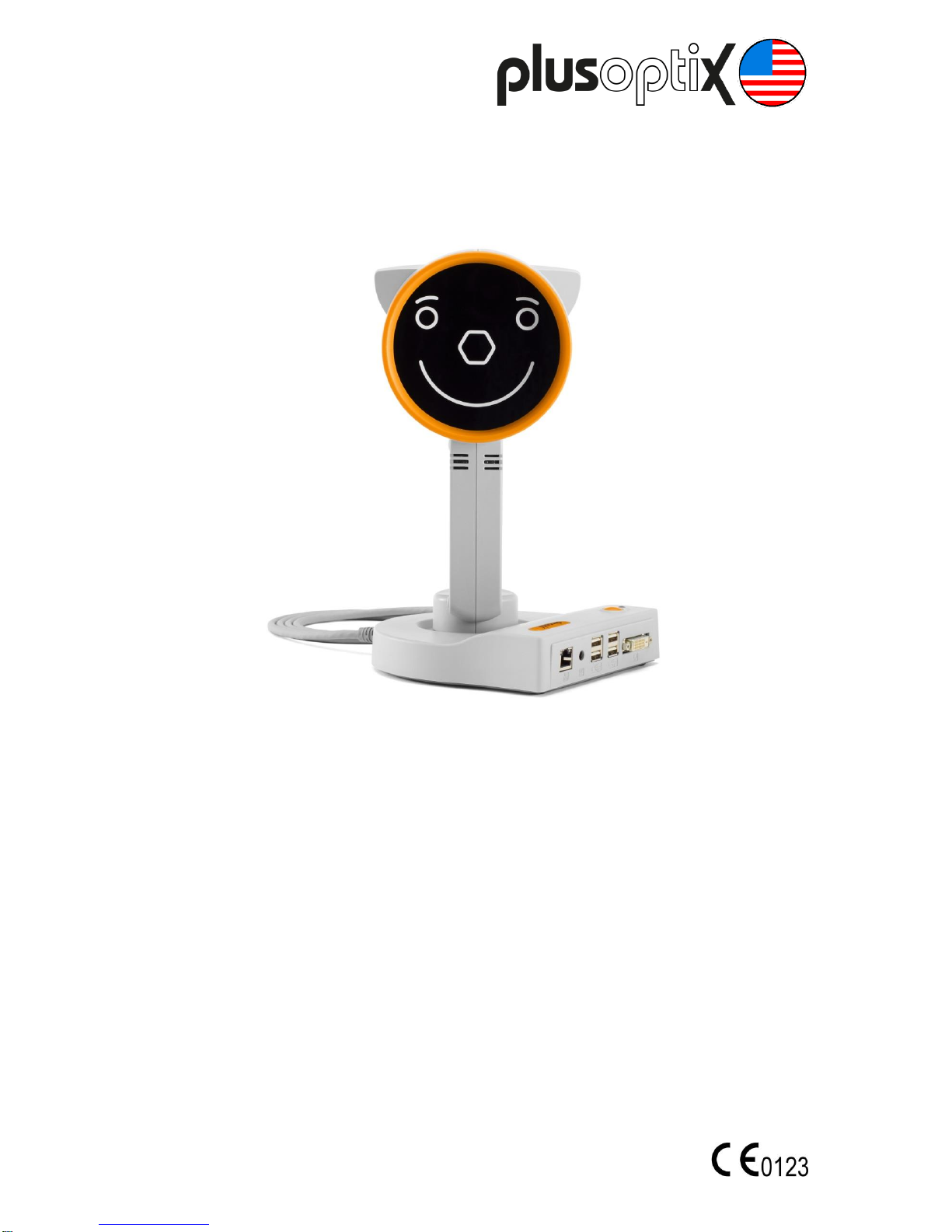
Vision Screener
„plusoptiX S16”
User Manual
Edition: 10/31/2018 - CAD
Plusoptix GmbH
Neumeyerstrasse 48
90411 Nürnberg
Germany
www.plusoptix.com
Englisch
Page 2

Page 2/22
Table of contents
1 Intended use and responsibility of the operator ............................................................. 3
2 Checking the scope of delivery ...................................................................................... 6
3 Learning about the „plusoptiX S16“ and connecting it .................................................... 7
3.1 Connecting the „plusoptiX S16“ ................................................................................8
3.2 Integrated interfaces.................................................................................................9
3.3 Connecting an external monitor (optional) ................................................................9
3.4 Connecting the USB keyboard and mouse (optional) ...............................................9
4 Switching the “plusoptiX S16” on and off and adjusting settings .................................. 10
5 Screen displays and training videos ............................................................................ 11
6 Preparing the measurement area ................................................................................ 12
7 Performing measurements .......................................................................................... 12
7.1 Voraussetzungen für eine erfolgreiche Messung .................................................... 13
7.2 Selecting the referral criteria ................................................................................... 14
7.3 Starting the measurement and adjusting the “plusoptiX S16” ................................. 14
7.4 Checking and documenting the measurement results ............................................ 16
8 Maintenance, calibration, service and guarantee ......................................................... 17
9 Technical details about the “plusoptiX S16” ................................................................. 18
List of figures
Figure 1: “plusoptiX S16” in the box....................................................................................... 6
Figure 2: View of the device’s cradle ..................................................................................... 7
Figure 3: View of reverse side ............................................................................................... 8
Figure 4: Underside of the cradle with type plate ................................................................... 8
Figure 5: Setting the date and time .......................................................................................10
Figure 6: Switching between the home page, help page and training videos ........................11
Figure 7: Measuring environment .........................................................................................12
Figure 8: Selecting the referral criteria ..................................................................................14
Figure 9: Home screen ................................................................................................ .........14
Figure 10: Selection of the age group ...................................................................................15
Figure 11: Detecting the correct measuring distance ............................................................ 16
Figure 12: Overview of the results pages .............................................................................16
Figure 13: Type plate with serial number ..............................................................................17
List of supplementary short manuals
These can be found in the "Support" section of our homepage (www.plusoptix.com).
1. Adjusting settings and setting up WLAN
2. Preparing and performing a measurement
3. Viewing the measurement results
4. Entering, retrieving or deleting patient data
5. Documenting measurement results electronically
6. Documenting measurement results on paper
7. Exporting data
8. Downloading software updates
9. Troubleshooting malfunctions and measuring interruptions
Page 3
Page 3/22
1 Intended use and
responsibility of the operator
Thank you for choosing to purchase the “plusoptiX S16”! Plusoptix is the global leader in the
development, production and distribution of medical measuring devices for pediatric Vision
Screening. If you have any further questions after reading this user manual, please do not
hesitate to contact us. The symbols in this user manual have the following meanings:
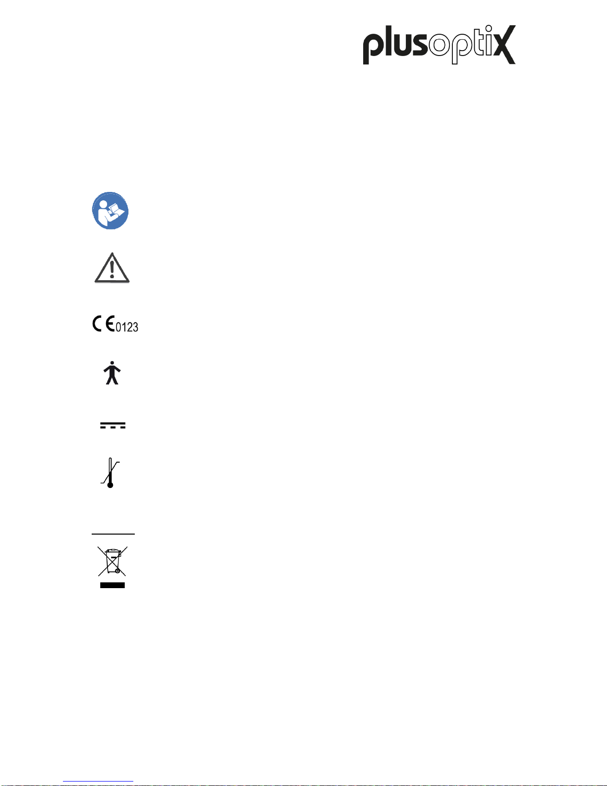
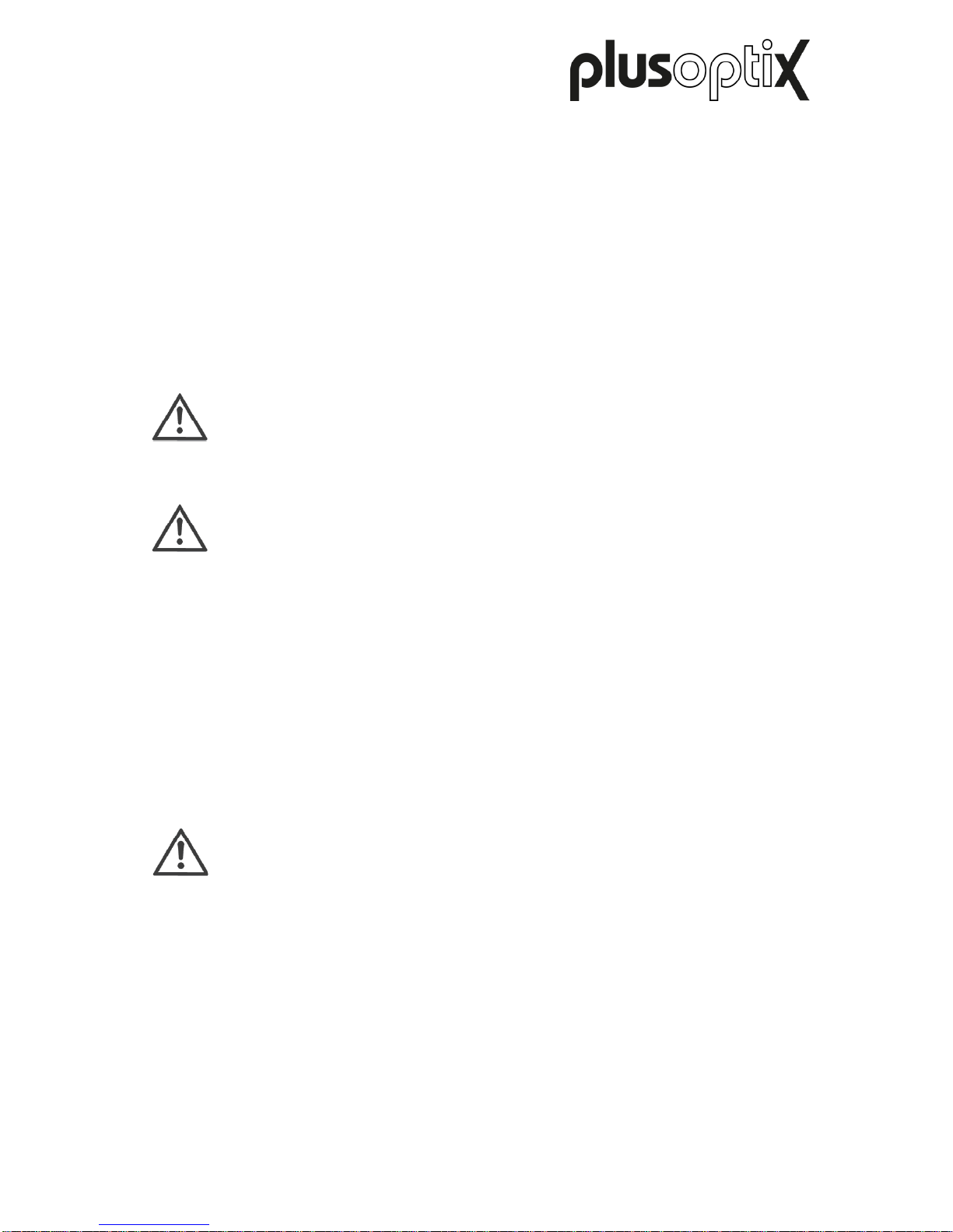
Please read this user manual before using the “plusoptiX S16” for the first time! It
explains the device’s functions. When the “plusoptiX S16” is switched on,
additional training videos can be accessed by touching the blue “?”.
Warnings and tips are labelled with the Attention! symbol.
The “plusoptiX S16” fulfils the requirements of Medical Devices Directive
2007/47/EEC.
The “plusoptiX S16” fulfils the requirements for a Type B applied part of IEC
60601-1.
Only connect the “plusoptiX S16” to the enclosed GSM36P12-P1J medical
power supply.
The “plusoptiX S16” can be stored and transported at a temperature between
0°C and +50°C (i.e. 32°F to 122°F). A temperature between +10°C and +40°C
(i.e. 50°F to 104°F) with a non-condensing air humidity of 20% to 80% is required
to operate the device.
Disposal
Do not dispose of the “plusoptiX S16” as domestic waste. Please send the
“plusoptiX S16” to Plusoptix (Plusoptix GmbH, Neumeyerstrasse 46, 90411
Nürnberg, Germany) for environmentally friendly recycling. Plusoptix will
reimburse you for the cost of the return.
0°C
+50°C
12V
Page 4

Page 4/22
Intended use
The “plusoptiX S16” is used for the early detection of visual disorders (preventative eye
care). These visual disorders can cause permanent loss of vision in an eye (amblyopia) if
they are not discovered and treated in the early years.
To detect visual disorders, the “plusoptiX S16” measures the sphere, cylinder, axis, line of
vision and pupil size of both eyes at the same time. Using these measurement values, the
spherical equivalent, gaze symmetry and interpupillary distance are calculated. All
measurement values are compared with age-dependent referral criteria. “Refer” is
automatically displayed as a precautionary result for every patient requiring an
ophthalmologist appointment.
Note:
Preventative eye care with the “plusoptiX S16” does not replace the eye
examination carried out by an ophthalmologist. An ophthalmologist remains the
only one who can interpret the measurement values and establish a diagnosis.
The measurement values must not be used directly to prescribe glasses or
contact lenses.
All children who are not already being treated by an ophthalmologist should undergo a
preventative eye care examination. The first preventative eye care examination should be
carried out at the age of one. They should then be repeated regularly, as the eyes can
change during growth and new visual disorders can appear at any time. All children with a
“Refer” result from the preventative eye care examination should be referred for an eye
examination with an ophthalmologist.
Note:
False-positive and false-negative results can occur in any type of preventative
examination.
Page 5
Page 5/22
Responsibility of the operator
- The operator is responsible for ensuring that only trained users handle the
“plusoptiX S16”.
- Training must at least include reading the user manual and a briefing about the operation
of the “plusoptiX S16”.
The briefing about the operation of the “plusoptiX S16” can be carried out by a previously
trained user. In addition to this, briefings are also provided by Plusoptix and by Plusoptix
dealers authorised by Plusoptix.
- The operator is responsible for ensuring that external devices that are connected to the
“plusoptiX S16” meet the standards of IEC 60601-1 and IEC 60601-1-1 when attached to
the “plusoptiX S16”.
- The operator is informed that opening the “plusoptiX S16” runs the risk of receiving an
(invisible) electric shock. The “plusoptiX S16” loses its approval as a medical product
when it is opened. The operator is responsible for ensuring that the “plusoptiX S16” is only
opened by Plusoptix or a dealer authorised by Plusoptix for service or warranty cases.
Warning:
Use of accessories, transducers and cables other than those specified or
provided by the manufacturer of this equipment could result in increased
electromagnetic
emissions or decreased electromagnetic immunity of this equipment and result in
improper operation.
Warning:
Use of this equipment adjacent to or stacked with other equipment should be
avoided because it could result in improper operation. If such use is necessary, this
equipment
and the other equipment should be observed to verify that they are operating
normally
Page 6
Page 6/22
2 Checking the scope of delivery
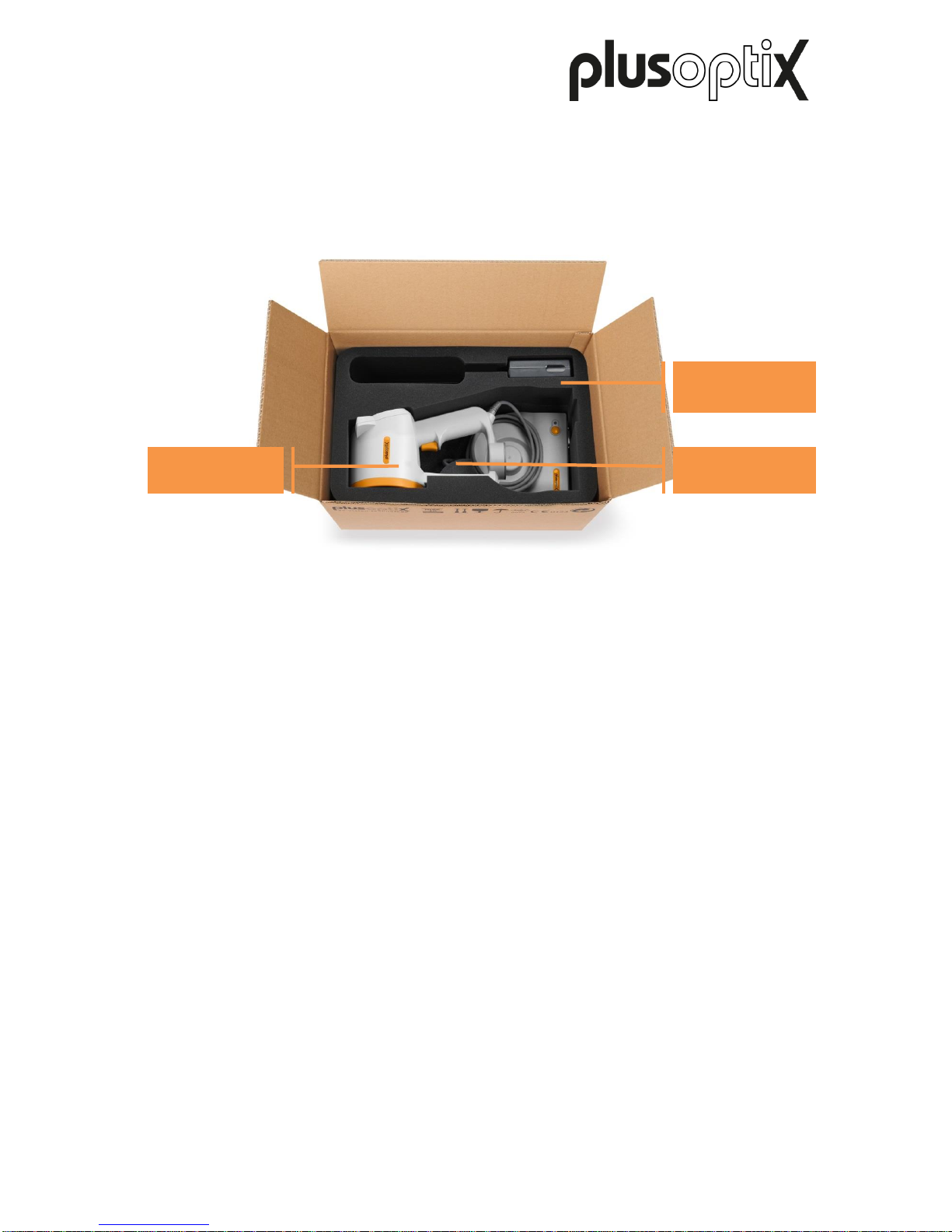
The “plusoptiX S16” is delivered in a box with foam inserts, which protect the “plusoptiX S16”
from damage. If the box shows any signs of damage upon delivery, please immediately
inform the vendor of the “plusoptiX S16”.
On delivery, please check that the contents of the box are complete. The scope of delivery
includes:
- User manual for the “plusoptiX S16”
- Vision Screener “plusoptiX S16”
- GSM36P12-P1J medical power supply
- Power cord (in the compartment under the device)
Optional accessories:
- Wireless “plusoptiX P12” label printer
- Self-adhesive labels for the “plusoptiX P12”
If the delivery is incomplete, please inform the seller of the “plusoptiX S16” immediately.
230V power
Medical power
supply
plusoptiX S16
Figure 1: “plusoptiX S16” in the box
Page 7
Page 7/22
3 Learning about the „plusoptiX S16“ and connecting it
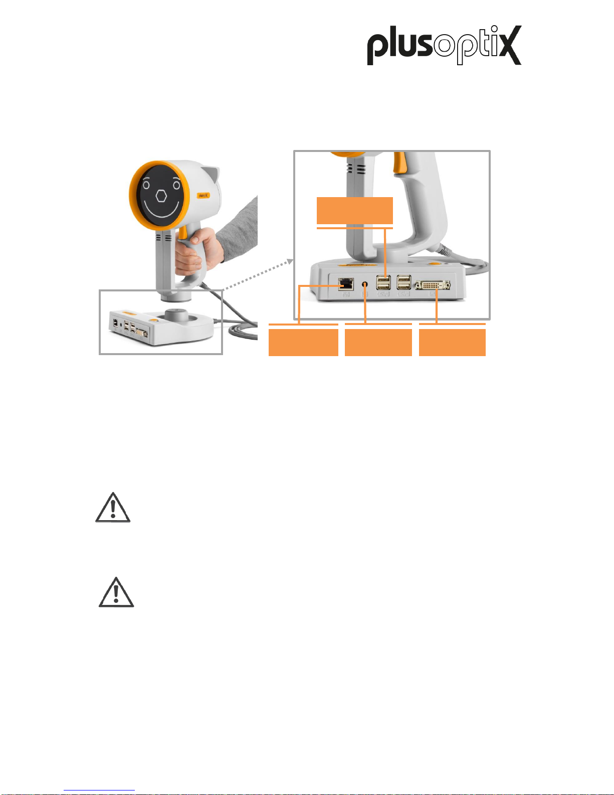
The “plusoptiX S16” is made up of the device with a smiley, which is connected to the cradle
with the device cable.
During a measurement, the “plusoptiX S16” records a series of images. To ensure children
look into the camera during the measurement, the “plusoptiX S16” plays a warble sound.
The speaker, the camera lens and the LEDS needed to light the images are located behind
the black protective screen with the smiley. This smiley helps to keep the child’s attention.
Attention:
If a child is not looking at the camera lens in the middle behind the hexagon
during the measurement, this can lead to a cancellation of the measurement or
incorrect measured values of the visual symmetry. Therefore do not use any
other external fixation aids!
Note:
So that the protective screen does not get dirty, we recommend you do not touch
it. Should the protective screen get dirty, please heed the care instructions in
Chapter 8.
LAN (RJ-45)
DVI
4 x USB
12V
Figure 2: View of the device’s cradle
Page 8
Page 8/22
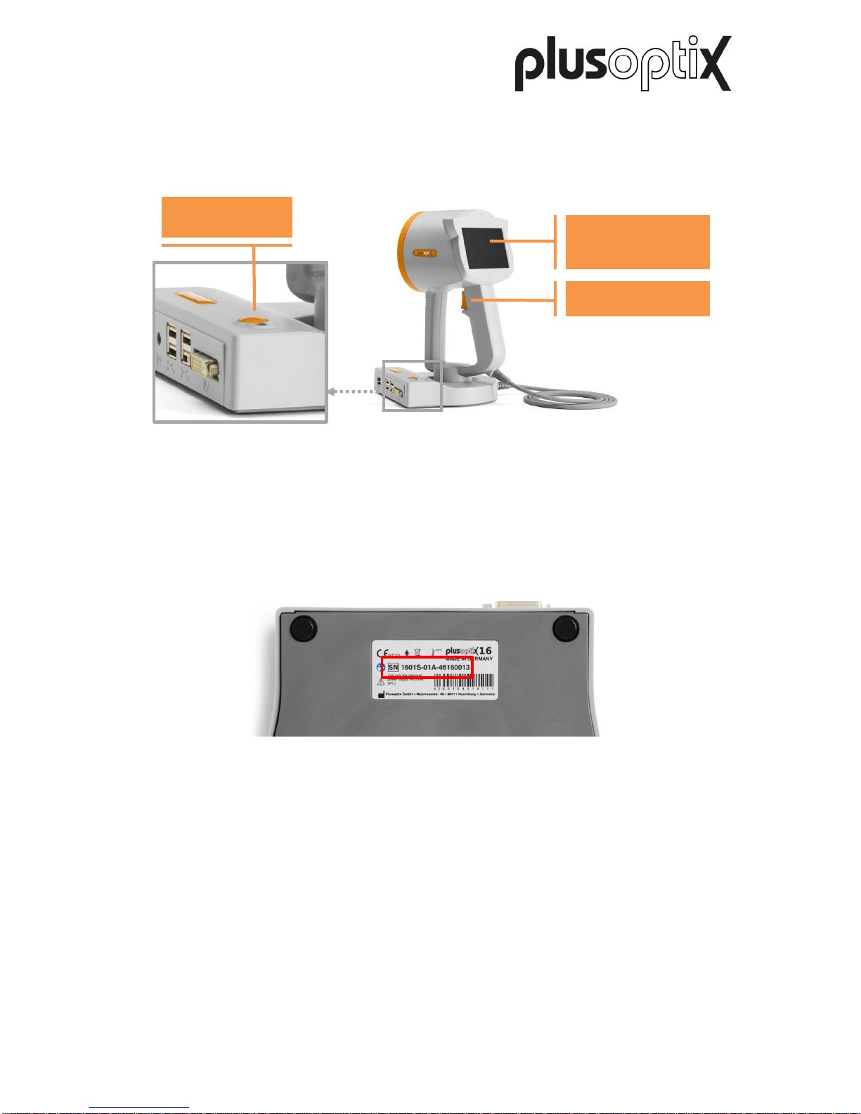
There is a 4.3” screen (resistive touchscreen) on the back of the “plusoptiX S16”. To access
a function displayed on the screen, simply tap the screen with your fingernail. The screen
and contact sensor are protected behind a thin plastic cover.
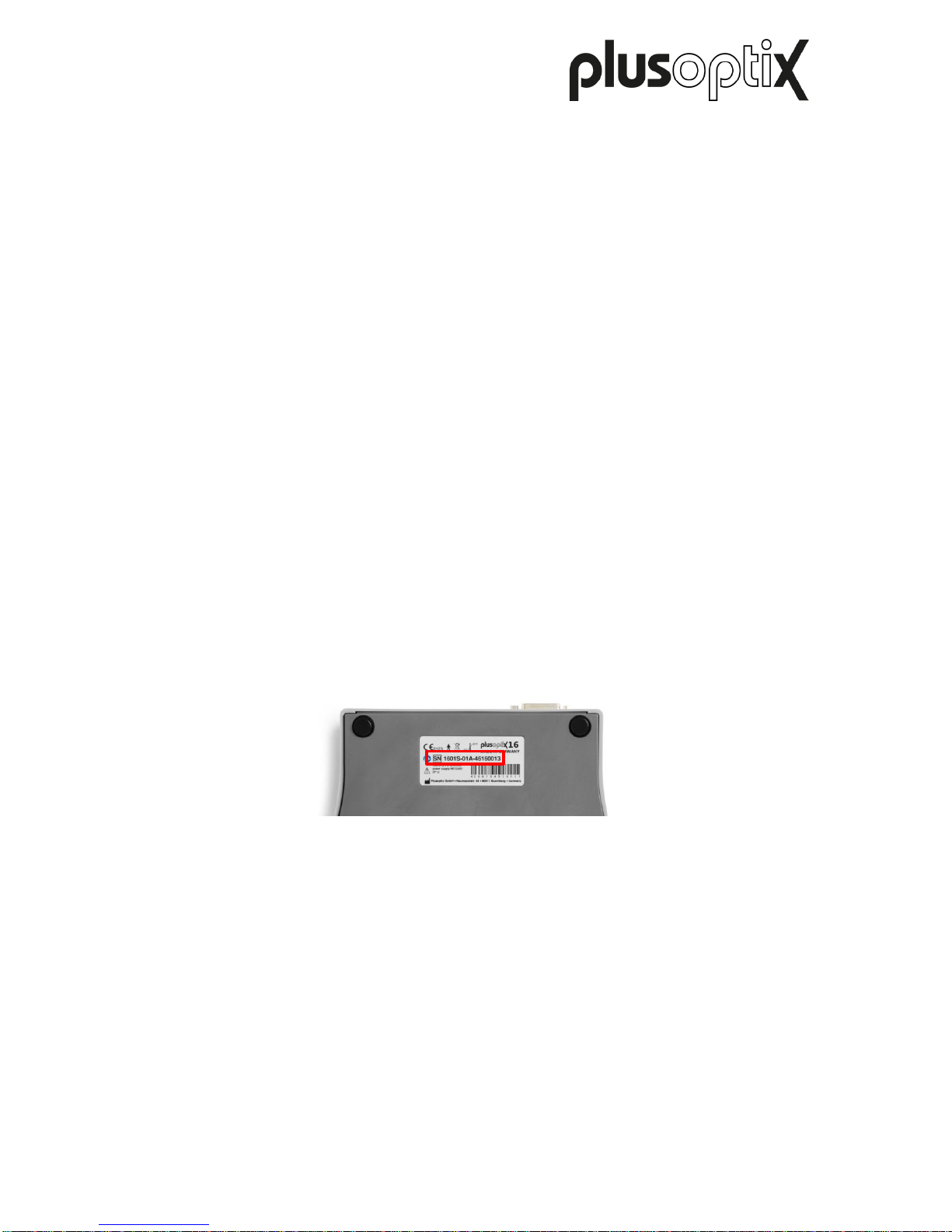
The type plate with serial number (S/N 1601A-xxx-xxxx xxxx) can be found on the bottom of
the cradle. If you contact us regarding ongoing service or guarantee issues, please make
sure you always have the serial number of your “plusoptiX S16”. The serial number helps us
to answer your question quickly.
3.1 Connecting the „plusoptiX S16“
Connect the medical power supply to the power cord and then plug this in. The LED on the
power supply lights up green for confirmation. Then connect the medical power supply to the
“plusoptiX S16”.
Trigger
4.3”‘ screen
(touchscreen)
On / off button
Figure 3: View of reverse side
Figure 4: Underside of the cradle with type plate
Page 9

Page 9/22
3.2 Integrated interfaces
The cradle has 4 connections:
- LAN connection (RJ45) for incorporation into the practice network
- 12V connection for the medical power supply
- 4 x USB interfaces
- DVI connection for optional connection of a monitor
The four USB interfaces can be used as follows:
- To save the screening reports and import an infographic
- To import patient data
- To export data
- Optional connection of a USB keyboard and USB mouse
3.3 Connecting an external monitor (optional)
The “plusoptiX S16” has a DVI interface to connect an external monitor. This enlarges the
display of the results pages. This allows the results pages to be discussed easily with the
patient.
Connect your monitor with the DVI interface in the cradle of the “plusoptiX S16”. When the
device is mounted on the cradle, the image is shown on the external monitor and the screen
of the “plusoptiX S16” is turned off.
Remove the device from the cradle before the measurement. The screen of the
“plusoptiX S16” is now active and the external monitor is switched off. This avoids the child
being distracted by the picture on the external monitor during the measurement.
After the measurement, replace the device on the cradle. The screen of the “plusoptiX S16”
is now turned off again and the screen of the monitor shows an enlarged view of the results
pages.
3.4 Connecting the USB keyboard and mouse (optional)
To enter data on the “plusoptiX S16”, it is necessary to connect a conventional USB
keyboard. Connect your input device with the USB interface of the “plusoptiX S16”. You can
also connect wireless input devices instead of cabled ones.
A USB keyboard is necessary for:
- inputting and selection of patient data
- entering the password in the WLAN settings
- configuring network settings to connect to the practice network
If a connected mouse or keyboard is not working, please check whether the USB keyboard
or mouse is switched on, connected with the “plusoptiX S16” and whether the batteries are
inserted. If your input device still doesn’t work, this means it is not supported by the drivers
installed in the “plusoptiX S16”. Use input devices from another manufacturer instead in this
case.
Note:
Non-functioning external input devices do not constitute a service or warranty
case!
Page 10
Page 10/22
4 Switching the “plusoptiX S16” on and off and adjusting settings
Press the On / Off button briefly to turn the device on. The screen will come on immediately
and the “plusoptiX S16” will start up. After approx. 30 seconds, the “plusoptiX S16” is ready
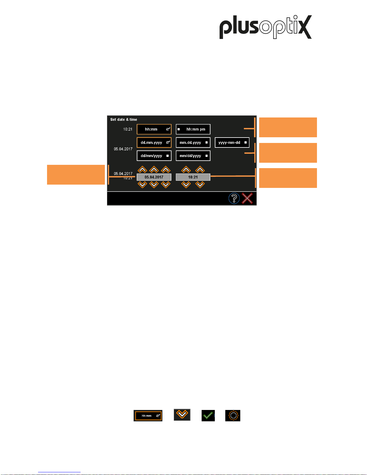
to operate. The first time you start the device up, you will see the data and time settings
page.
The selected time and date format is highlighted (1). Using the orange arrows (2), set the
right date and current time. Confirm your entries with the green checkmark (3). The date,
time and display format can be changed at a later date in the settings (4).
Zum Ausschalten drücken Sie kurz den Ein-/Aus-Taster. Der „plusoptiX S16“ fährt dann
herunter.
More information about adjusting the settings and implementing a WLAN connection can be
found in short manual 1 on our homepage (www.plusoptix.com), under support.
1) 2) 3) 4)
Time format
buttons
Date format
buttons
Setting the date
button
Setting the time
button
Figure 5: Setting the date and time
Page 11
Page 11/22
5 Screen displays and training videos
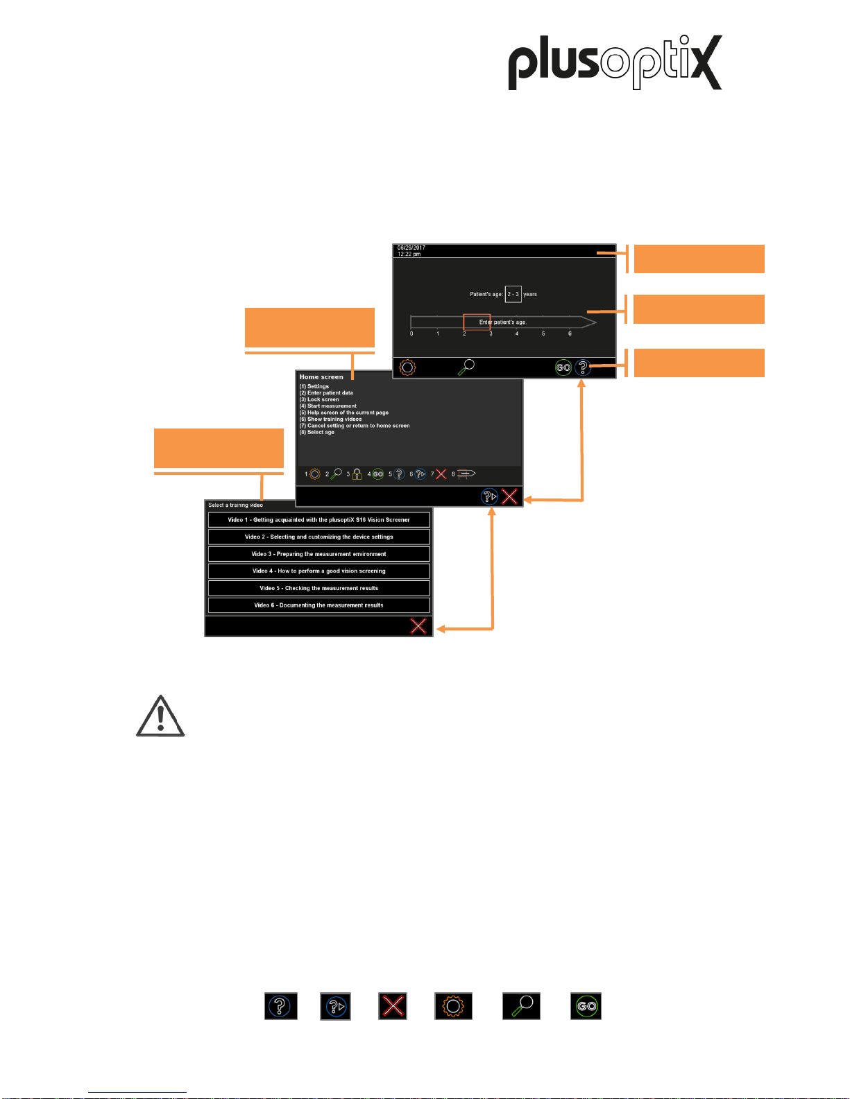
All the screen displays of the “plusoptiX S16” are the same. The header is above, the
information part in the middle and the navigation bar below. The button with the blue "?" (1)
takes you to the help page, which explains the displayed buttons. The button with the blue "?
►" (2) takes you to the overview of available training videos. The red "X" (3) takes you back
to the previous home page.
Note:
Watching training videos does not replace the need to read the user manual.
They serve only to aid visualisation of what is written in the user manual.
The header shows the status. This includes, among other things:
- Date and time on the left side
The navigation bar operates the device. Among other things, you can select:
- the gear wheel (4) to access the settings
- the magnifier (5) to call up the database
- the “GO” button (6) to start a measurement
(If the “GO” button is flashing, a measurement can be started by touching it)
- the blue “?” (1) to access the available training videos
- the red “X” (3) which interrupts without saving and returns you to the previous page.
1) 2) 3) 4) 5) 6)
Training videos
Information part
Navigation bar
Header
Help page
Figure 6: Switching between the home page, help page and training videos
Page 12
Page 12/22
6 Preparing the measurement area
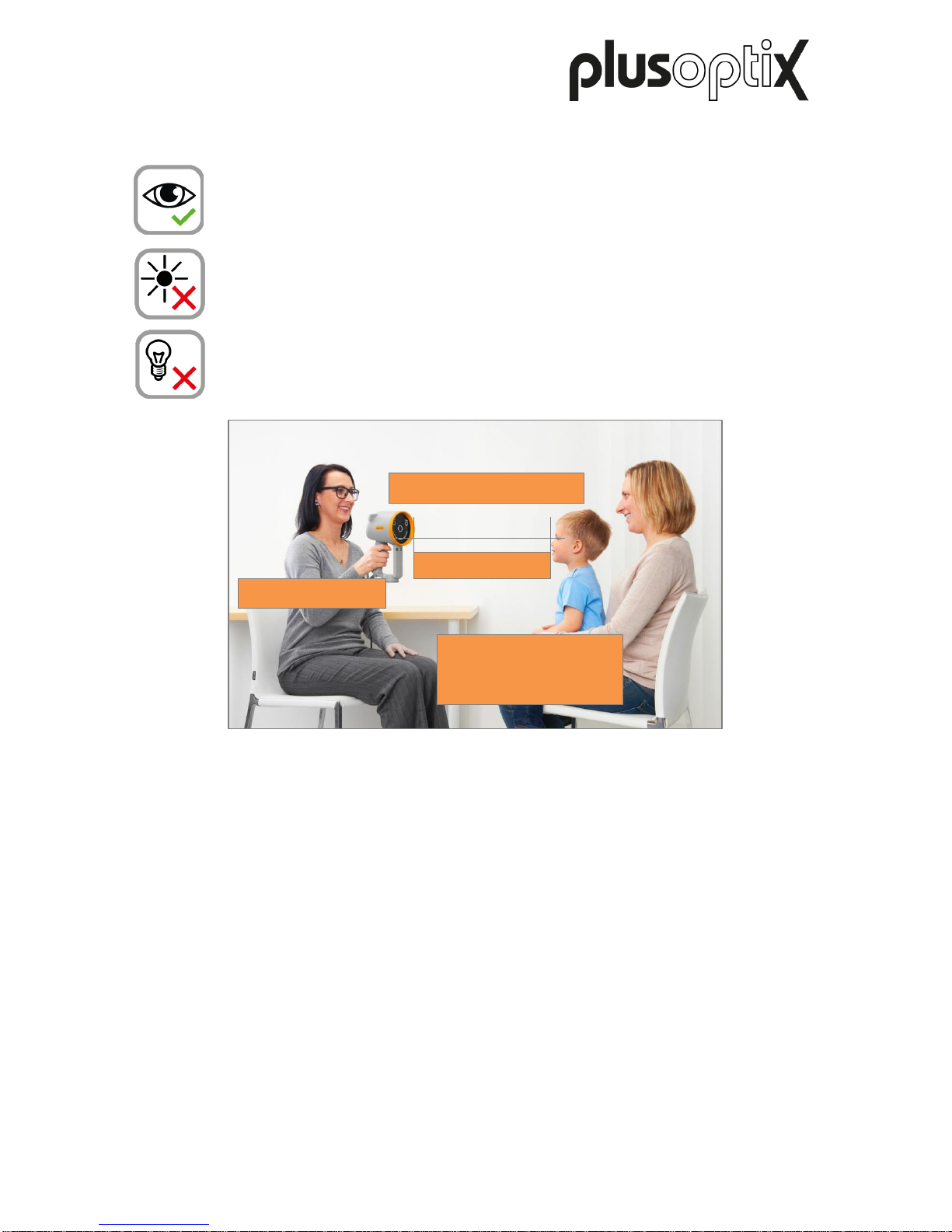
The measurement is carried out using infrared light, which is also contained in
sunlight and in the light of bulbs and halogen spotlights, for example. This infrared
light is invisible to the human eye and completely safe.
To obtain correct measurement values, it is important to avoid disruptive sources
of infrared light in the examination room. Close curtains, roller blinds and shutters
to block out the sun’s rays.
Turn off all light sources that produce heat. This does not mean that the
examination room should be dark. Cold light sources, such as energy saving bulbs
and neon lights, do not affect the measurement values.
More information about preparing the measurement area can be found in short manual 2 on
our homepage (www.plusoptix.com), under support.
7 Performing measurements
The “plusoptiX S16” measures both eyes at the same time (binocular) in 0.5 seconds from a
distance of one meter. This means that even infants with a short attention span can be
measured from the age of 5 months. The simultaneous measurement of both eyes also
facilitates a reliable comparison of both eyes’ measurement values. More information about
performing a measurement can be found in short manual 2 on our homepage
(www.plusoptix.com), under support.
A measurement can be performed anonymously or by indicating patient data. More
information about entering or retrieving patient data can be found in short manual 4 on our
homepage (www.plusoptix.com), under support.
1 meter
At eye level
No direct sunlight
Pupil diameter
Minimum of 4mm
Maximum of 8mm
Figure 7: Measuring environment
Page 13
Page 13/22
7.1 Preconditions for a successful measurement
a) The measuring distance is correct
The measuring distance must be between 95 cm and 105 cm. Check whether the
camera image on the screen is in focus. You must be able to see the individual hairs on
the eyelids or the eyelashes clearly on the camera image.
b) The patient is looking at the camera lens
The “plusoptiX S16” and the eyes of the patient must be aligned with one another. The
patient must look at the nose of the smiley face. For this reason, an attention grabbing
warble sound is emitted at the beginning of the measurement.
Note:
The attention span of toddlers is very short. Take advantage of the fact that the
examination room is unknown to the toddler. The attention-grabbing "Warble"
sound in this unknown environment always arouses interest. Avoid lengthy
conversation with parents before the measurement.
Note:
If a child is not looking at the nose of the smiley face during the measurements,
this can cause a termination of the measurement or inaccurate measurement
values of the gaze symmetry. For this reason, do not use any other external
fixation aids!
c) Both of the patient’s pupils should be completely visible
The pupils must not be covered by eyelids, eyelashes or hair, for example. Check
whether both pupils can be seen completely on the screen and whether they are
encircled in green.
d) Both pupil diameters must be between 4 and 8 mm
Note:
If a red error message is displayed, an action recommendation is also displayed
below it. Please read short manual 9 on our homepage (www.plusoptix.com),
under support.
Page 14
Page 14/22
7.2 Selecting the referral criteria
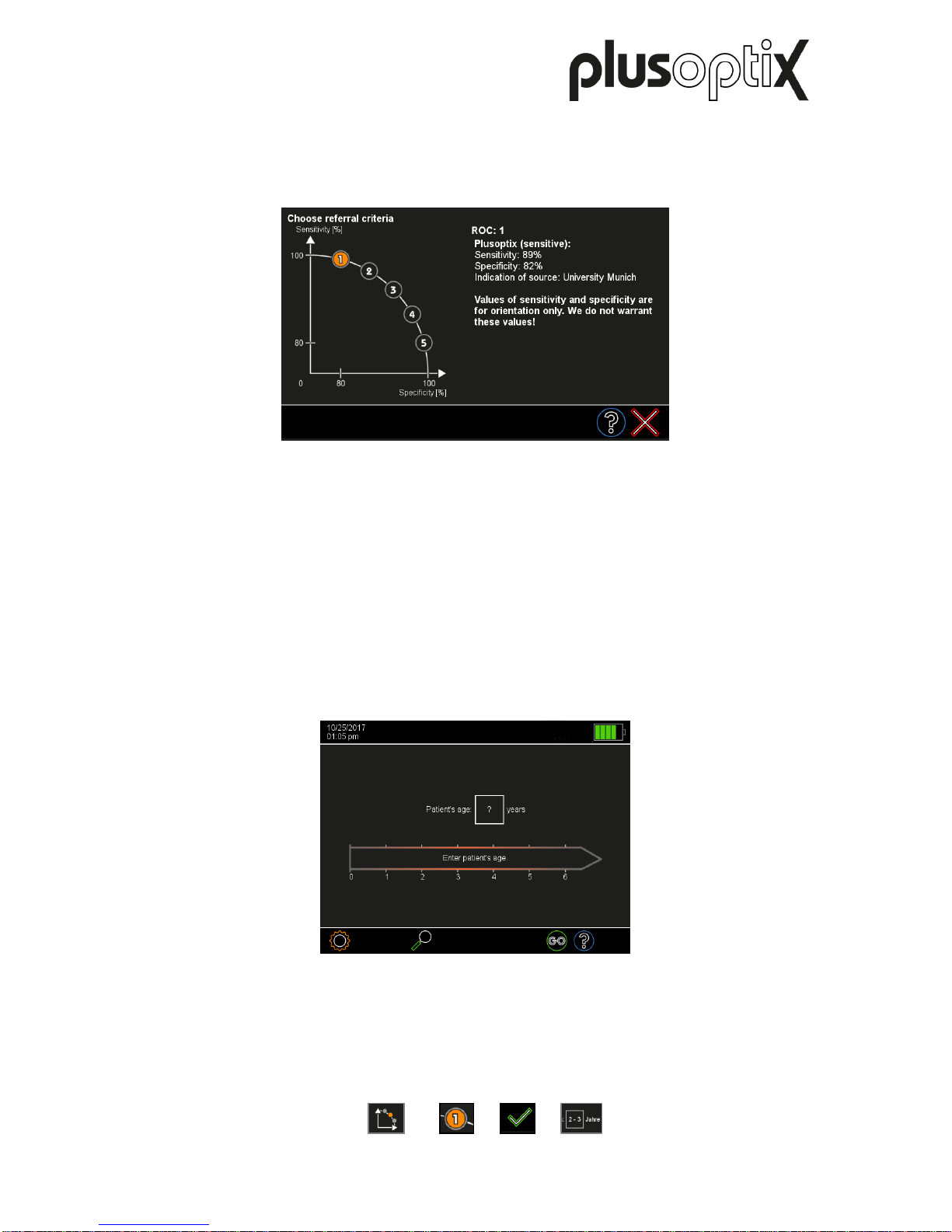
Touch the button to choose the referral criteria (1) in the settings. There are five validated
groups of referral criteria to choose from (see figure 23).
These five groups are called ROC 1, ROC 2, ROC 3, ROC 4 and ROC 5. Each of these
groups defines different, age-dependent thresholds, which lead to a “Refer” preventive test
result. These five groups are shown along a schematic ROC (Receiver Operating
Characteristic) curve. Select a group by touching the relevant button (2) and confirm by
touching the green checkmark (3).
7.3 Starting the measurement and adjusting the “plusoptiX S16”
After you have set the time and date, the home page will be displayed every time you turn
the “plusoptiX S16” on again.
Figure 9: Home screen
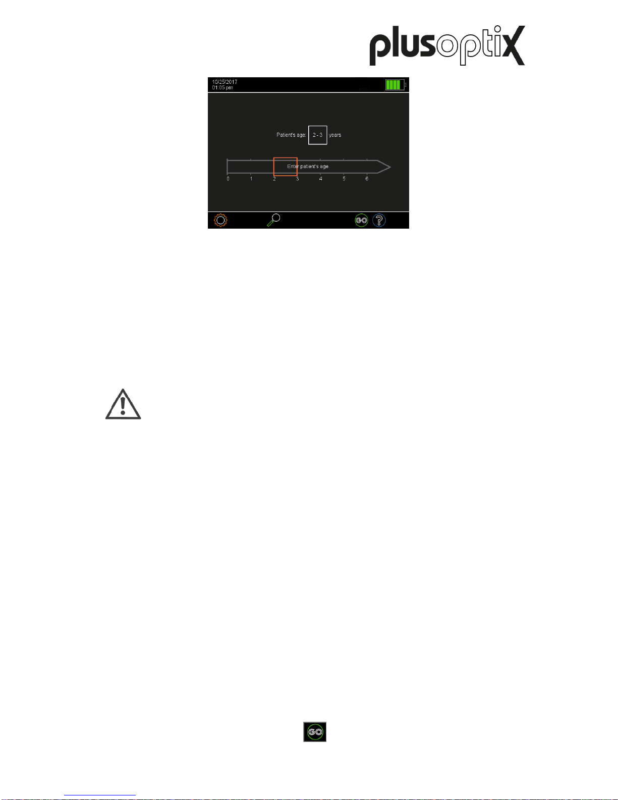
Select an age group by touching the appropriate age range (see Figure 4). You must select
the age group (4) in order to ensure the measurement values of the patient are compared
with the correct age-specific referral criteria (see Chapter 7.2 “Selecting the referral criteria”).
1) 2) 3) 4)
Figure 8: Selecting the referral criteria
Page 15
Page 15/22
Figure 10: Selection of the age group
- Hold the “plusoptiX S16” at eye level to the child, about 1.2 meters away. The measuring
distance is one meter, but it requires practice to correctly estimate this measuring distance
in one go. It is easier to hold the “plusoptiX S16” somewhat further away at the start of the
measurement and then slowly move it towards the child.
- By touching the flashing “GO” button (1) or pressing the trigger, you will start the camera
and a warble sound will be heard. You can now see the camera image on the screen.
Note:
A started measurement can be aborted by touching the screen.
- Adjust the “plusoptiX S16” so that both eyes can be seen on the screen and then slowly
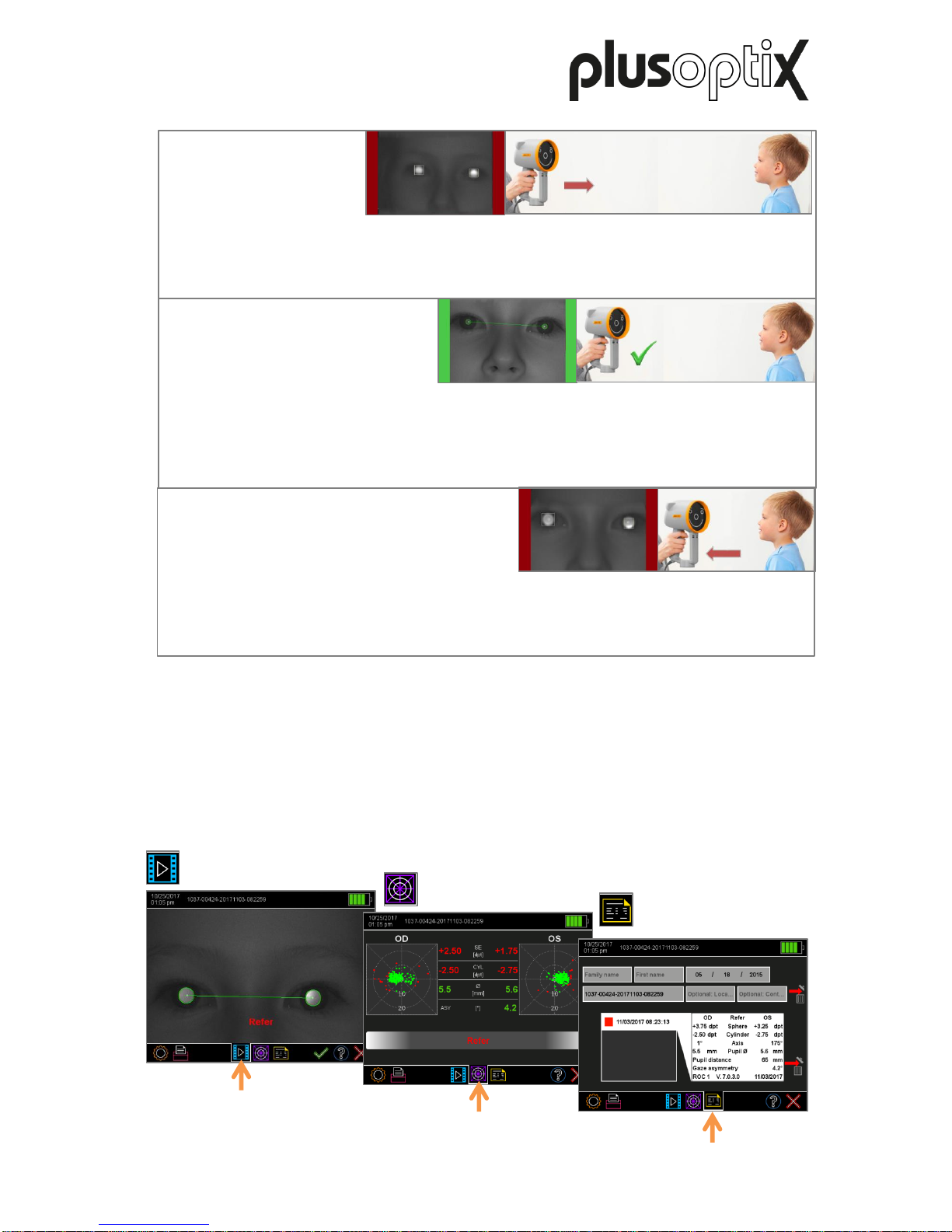
move the “plusoptiX S16” towards the patient until the camera image can be seen in highdefinition on the screen. Firstly, the pupils will be surrounded by white squares (the image
is still very blurred), then with red and finally with green circles (see Figure 11).
1)
Page 16
Page 16/22
The image is blurry and two red bars will be displayed next to the camera image. As the
measuring distance is too great, you can see the head of the patient virtually in its entirety.
Move the “plusoptiX S16” towards the patient until the camera image can be seen in high-
definition on the screen and both pupils are encircled in green.
The image is blurry and two red bars will be displayed next to the camera image. As the
measuring distance is too small, the eyes can be seen on the screen. Move the “plusoptiX
S16” away from the patient until the camera image can be seen in high-definition on the
screen and both pupils are encircled in green.
The image can be seen in high-definition on the screen, the bars are green and both pupils
are encircled in green. As soon as both pupils are surrounded by a green circle, the line
between the pupils turns green and another warble sound can be heard. The
“plusoptiX S16” is now a metre away from the child and the measurement begins
automatically. A “ping” sound signalises the end of the measurement.
Results page
“camera image”
Results page
“measurement values”
Results page “database”
(only plusoptiX S16)
7.4 Checking and documenting the measurement results
As space on the screen is limited, the measurement results are spread across a total of three
results pages. After the measurement, you will first see the “camera image” results page. By
touching the appropriate symbol in the middle of the navigation bar, you can access each of
the three results pages. More information about checking and documenting the
measurement results can be found in short manual 3, 5 and 6 on our homepage
(www.plusoptix.com), under support.
Figure 12: Overview of the results pages
Figure 11: Detecting the correct measuring distance
Page 17
Page 17/22
8 Maintenance, calibration, service and guarantee
The “plusoptiX S16” is an opto-electronic measuring device. The mechanical structure and
functional principle is comparable to a video camera. If you handle the “plusoptiX S16” as
carefully as you handle your own video camera, your “plusoptiX S16” will provide you with
many years of problem-free, good service.
Maintenance and calibration
The “plusoptiX S16” is maintenance-free and does not need calibrating. If it is not being
used, store it in the box for safekeeping. Only use a slightly damp microfibre cloth to clean
the device.
Service
If the “plusoptiX S16” is not working perfectly, please read chapter Fehler! Verweisquelle
konnte nicht gefunden werden. “Fehler! Verweisquelle konnte nicht gefunden werden.”
or short manual 9 on our homepage (www.plusoptix.com), under support. Only contact
Plusoptix if this is subsequently necessary.
Garantie
Es besteht eine 12-monatige Garantie ab der Inbetriebnahme. Sie können eine Verlängerung
der Garantiezeit erwerben. Kontaktieren Sie dazu bitte Plusoptix. Die Garantie erlischt bei
äußeren Beschädigungen, unsachgemäßem Betrieb, falschem Reinigen oder Transport
ohne Gerätekarton. Die Garantie erlischt auch, wenn der „plusoptiX S16“ geöffnet worden ist.
Externe Geräte wie USB-Speicher, USB-Tastatur und -Maus sind nicht im Garantieumfang
enthalten.
Serial number of the “plusoptiX S16”
The type plate with serial number (S/N 1601S-xxx-xxxx xxxx) can be found on the bottom of
the cradle. If you contact us regarding ongoing service or guarantee issues, please make
sure you always have the serial number of your “plusoptiX S16”. The serial number helps us
to answer your question quickly.
Posting the “plusoptiX S16”
If case of a guarantee claim or service, please send to “plusoptiX S16” to us in its box at your
expense. We will then return it to you at our expense after we have repaired it. If patient data
is stored on the device, it must be removed from the device for data protection reasons. For
this purpose, a copy of the database can be exported before shipping, and imported again
after the receipt of the repaired device. For more information, refer to short manual 7 on our
homepage (www.plusoptix.com), under support.
Our address is:
In Europe:
Plusoptix GmbH
Neumeyerstrasse 46
90411 Nuremberg
Germany
Tel: +49-911-59 83 99-20
in North- and South America:
Plusoptix Service & Warranty
Attn: Richard Christensen
8736 SE 165th Mulberry Lane
Suite 220
Lady Lake, Fl 32162
Figure 13: Type plate with serial number
Page 18
Seite 18/22
9 Technical details about the “plusoptiX S16”
Measurement values
Metered value
Measurement range and tolerance
Sphere
-7 to +5 dpt in 0.25 dpt steps ± 0.25 dpt
Cylinder
-7 to +5 dpt in 0.25 dpt steps ± 0.25 dpt
Axis
1 to 180° in 1° steps ± 15°
Spherical equivalent
-7 to +5 dpt in 0,25 dpt increments ± 0,25 dpt
Pupil diameter
3 to 8 mm in 0.1 mm steps ± 5%
Gaze asymmetry
0 to 25° in 0.1° steps ± 5%
Interpupillary distance
25 to 85 mm in 0.1 mm steps ± 5%
Interfaces and standards
Interfaces
USB, DVI, IR
WLAN, LAN (RJ-45)
“plusoptiX S16” screen
Diagonal 4.3‘‘, aspect ratio 5:3 (800 x 480 pixels)
Resistive contact sensor
Standards
IEC 60601-1
IR
Plusoptix devices use infrared light with a wavelength of
870nm and a maximum intensity of 135mW/sr.
WLAN interface standards:
Physical layer
Supports 802.11 b and g standards
Network architecture types
Communication with cabled networks via access points
Security
WPA and WPA2
Transmit power
802.11b/g: 50 mW (+17 dBm) typically
Frequency range
2,400 - 2,4897 GHz
Operating channels
1-11 for North America and other,
1-13 for Europe and other
Channels
Supports all channels of 802.11d-APs.
RX sensitivity
-86 dBm typically @ 11 Mbps,
-82 dBm @ 6 Mbps,
-69 dBm @ 54 Mbps
Data rates
802.11g: 6, 9, 12, 18, 24, 36, 48, 54 Mbps
802.11b: 1, 2, 5.5, 11 Mbps
Power supply
Only use the GSM36P12-P1J power supply provided.
Medical power adapter
(GSM36P12-P1J power supply)
Input
100 - 240 VAC, 50/60 Hz, 0,9 - 0,45 A
Output
12 VDC, 3A, 36 W max.
Page 19
Page 19/22
Environmental conditions for operation and storage
The plusoptiX 16 has been designed for the environment category "Environment in areas of
domestic health care, except for vehicles and planes”. “plusoptiX 12” can be stored in its box.
Do not put the box near heat sources (radiators, fan heaters, etc.). When you remove the
“plusoptiX 12” from its box for use, do not place it in the sunlight.
Storage
Temperature
0 to +50°C
Humidity
10 to 80% non-condensing
Operation
Temperature
+10 to +40°C
Humidity
20 to 80% non-condensing
Max. Height
Max. storage height
<2000m (78,740’’)
Max. operational height
<2000m (78,740’’)
Dimensions and weight with and without the box
plusoptiX S16
without cradle
without box
Dimensions (HBD)
165 x 140 x 248 mm (6½ x 5½ x 9¾ in)
Weight
0,7 kg (24.7 oz)
plusoptiX S16
without box
Dimensions (HBD)
190 x 155 x 265 mm (7½ x 6⅛ x 10¾ in)
Weight
1,8 kg (52.9 oz)
plusoptiX S16
in the box
Dimensions (HBD)
270 x 420 x 210 mm (10⅝ x 16½ x 8¼ in)
Weight
2,7 kg (93.5 oz)
Manufacturer’s declaration about electromagnetic compatibility (EMC)
The “plusoptiX 16” is intended for use in the electromagnetic environments listed below.
Owners and holders of the “plusoptiX 16” are responsible for guaranteeing this environment.
This product conforms to the EMC standard (IEC 60601 -1 -2).
Note:
This equipment has been tested and found to comply with the limits for a Class B
digital device, pursuant to part 15 of the FCC Rules. These limits are designed to
provide reasonable protection against harmful interference in a residential
installation. This equipment generates, uses and can radiate radio frequency
energy and, if not installed and used in accordance with the instructions, may
cause harmful interference to radio communications. However, there is no
guarantee that interference will not occur in a particular installation. If this
equipment does cause harmful interference to radio or television reception, which
can be determined by turning the equipment off and on, the user is encouraged to
try to correct the interference by one or more of the following measures:
Reorient or relocate the receiving antenna
Increase the separation between the equipment and receiver
Connect the equipment into an outlet on a circuit different from that to which the
receiver is connected
Consult the dealer or an experienced radio/TV technician for help
Page 20

Page 20/22
Emissions Test
Conformity
Electromagnetic environment - Instructions
RF Emission CISPR 11
Group 1
The radiation is low and causes no interferences with
electronic devices found nearby.
RF Emission CISPR 11
Category B
The “plusoptiX S16” can be used in all areas which
are connected to the public mains supply.
Harmonic Emissions
IEC 61000-3-2
Category A
Voltage fluctuations /
Flicker IEC 61000-3-3
Complies
Immunity Test
IEC 60601 test values
Conformity values
Electromagnetic
environment Instructions
ESD IEC 61000-4-2
± 8 kV contact
± 2, 4, 8, 15 kV air
± 8 kV contact
± 2, 4, 8, 15 kV air
The floor should be
made of wood, ceramic
or stone. If the floor is
covered with a
synthetic material, the
relative air humidity
should not be less than
30%.
Electrical fast
transient / burst
IEC 61000-4-4
± 2 kV
± 2 kV
Only plugs that are
usually available in
domestic or clinical
areas should be used.
Surge
IEC 61000-4-5
± 0.5 kV
± 1 kV
± 2 kV
± 0.5 kV
± 1 kV
± 2 kV
Only plugs that are
usually available in
domestic or clinical
areas should be used.
Voltage dips, short
interruptions on
power supply input
lines IEC 61000-411
0% 0.5 cycles
@ 0°, 45°, 90°, 135°,
180°, 225°, 270°, 315°
0% 1 cycle
70% 25 cycles
0% 250 cycles
0% 0.5 cycles
@ 0°, 45°, 90°, 135°,
180°, 225°, 270°, 315°
0% 1 cycle
70% 25 cycles
0% 250 cycles
Only plugs that are
usually available in
domestic or clinical
areas should be used.
Power frequencies
and magnetic fields
IEC 61000-4-8
30 A/m, 50/60Hz
30 A/m, 50/60Hz
Magnetic fields should
not exceed the usual
areas.
Page 21
Page 21/22
Immunity test
Testing level acc. to
IEC 60601
Conformity results
Electromagnetic environment –
Instructions
Conducted RF disturbances
IEC 61000-4-6
3 V
0.15 MHz – 80 MHz
6 V
in ISM and amateur
radio bands between
0.15 MHz and 80 MHz
80 % AM at 1 kHz
3 V
0.15 MHz – 80 MHz
6 V
in ISM and amateur
radio bands between
0.15 MHz and 80 MHz
80 % AM at 1 kHz
120V / 60 Hz
230V / 50 Hz
3 V
0.15 MHz – 80 MHz
6 V
in ISM and amateur
radio bands between
0.15 MHz and 80 MHz
80 % AM at 1 kHz
3 V
0.15 MHz – 80 MHz
6 V
in ISM and amateur
radio bands between
0.15 MHz and 80 MHz
80 % AM at 1 kHz
120V / 60 Hz
230V / 50 Hz
Portable and mobile radio equipment
must not be operated in a distance
to „plusoptiX 16“ (including the electrical
lines) less than the recommenced safe
distance calculated using the
appropriate equation for the
transmission frequency.
Recommended safe distance:
d=(3.5/10) x √ P
d=(3.5/10) x √ P 80MHz - 800MHz
d=(7/10) x √ P 800MHz – 2.7GHz
where P is the maximum output power
rating of the transmitter in watts (W) as
indicated by the transmitter
manufacturer and “d” is the
recommended safe distance in metres
(m).
The field strength of fixed RF
transmitters
as determined by a site survey should
be less than the compliance level in
each frequency range.
Interference may occur in the vicinity of
equipment marked by the
symbol shown.
Radio-frequency electromagn.
fields
IEC 61000-4-3
10 V/m
80 MHz - 2.7GHz
80% AM, 1KHz
27 V/m
385 MHz
PM 50%, 18 Hz
28 V/m
450 MHz
PM 50%, 18 Hz
9 V/m
710,745,780 MHz
PM 50%, 217 Hz
28 V/m
810, 870, 930 MHz
PM 50%, 18 Hz
28 V/m
1720, 1845, 1970 MHz
PM 50%, 217 Hz
28 V/m
2450 MHz
PM 50%, 217 Hz
9 V/m
5240, 5500, 5785 MHz
PM 50%, 217 Hz
10 V/m
80 MHz - 2.7GHz
80% AM, 1KHz
27 V/m
385 MHz
PM 50%, 18 Hz
28 V/m
450 MHz
PM 50%, 18 Hz
9 V/m
710,745,780 MHz
PM 50%, 217 Hz
28 V/m
810, 870, 930 MHz
PM 50%, 18 Hz
28 V/m
1720, 1845, 1970 MHz
PM 50%, 217 Hz
28 V/m
2450 MHz
PM 50%, 217 Hz
9 V/m
5240, 5500, 5785 MHz
PM 50%, 217 Hz
COMMENT 1 At 80 MHz and 800 MHz, the higher frequency range applies.
COMMENT 2 These guidelines may not apply in all situations. Electromagnetic propagation is affected by absorption and
reflection from structures, objects and people.
Page 22
Page 22/22
Attention:
Portable RF communications equipment (including peripherals such as antenna
cables and external antennas) should be used no closer than 30 cm (12 inches)
to any part of the “plusoptiX 16”, including cables specified by the manufacturer.
Otherwise, degradation of the performance of this equipment could result. The
“plusoptiX 16” is not compatible to HF SURGICAL EQUIPMENT.
Recommended safety distances between portable and mobile HF telecommunication devices and the “plusoptix 16”
The “plusoptiX S16” is intended for use in an electromagnetic environment with controlled HF disturbance variables. The
customer or user of the “plusoptiX S16” can contribute to avoiding electromagnetic disturbances, by complying with the minimum
distance between portable and mobile HF telecommunication devices (transmitters) and the “plusoptiX S16” – depending on the
output power of the communication device, as stated below.
Maximum output power of the
transmitter in W
Safety distance depending on the transmission frequency (in meters)
150 kHz - 80MHz
d = 0.35 √ P
80 MHz - 800MHz
d = 0.35 √ P
800 MHz - 2,7GHz
d = 0.7 √ P
0.01
0.035
0.035
0.07
0.1
0.11
0.11
0.22
1
0.35
0.35
0.7
10
1.11
1.11
2.21
100
3.5
3.5
7
For transmitters, whose maximum nominal output is not stated in the above table, the recommended safety distance in meters
(m) can be calculated using the equation from the relevant column, wherein P equals the maximum nominal output of the
transmitter in watts (W) as per information by the transmitter’s manufacturer.
COMMENT 1 At 80 MHz and 800 MHz, the higher frequency range applies.
COMMENT 2 These guidelines may not be applicable in all cases. The distribution of electromagnetic quantities is influenced by
absorption and reflections from buildings, objects and people.
 Loading...