

Page 1
Page 1 of 43
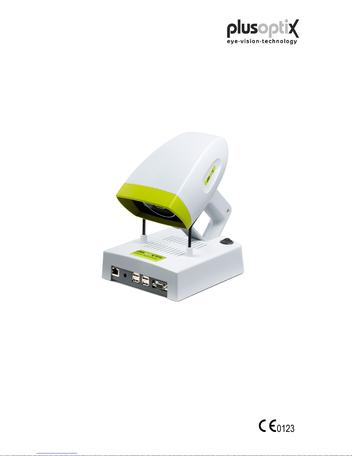
Pediatric Autorefractor
plusoptiX A09
INSTRUCTION MANUAL
(Version 5.0.20.0)
Plusoptix GmbH
Neumeyerstr. 48
90411 Nuernberg
Germany
www.plusoptix.eu
Englisch
Page 2

Page 2 of 43
Table of contents
1. Safety instructions ........................................................................................ 4
1.1 Warning and Symbols ................................................................................................. 4
1.2 Handling of the plusoptiX A09 ................................................................................... 5
1.3 Exclusive use of the plusoptiX A09 ............................................................................ 5
1.4 Operation of the plusoptiX A09 .................................................................................. 5
1.5 Duties of the operator .................................................................................................. 5
2. Delivery ....................................................................................................... 6
2.1 Storage ......................................................................................................................... 7
2.2 Unpacking .................................................................................................................... 7
2.3 Setting up ..................................................................................................................... 7
3. Connecting and switching on the system .................................................... 8
3.1 Connection ................................................................................................................... 8
3.2 Switching on the system .............................................................................................. 9
4. Settings ...................................................................................................... 10
4.1 General (Basic settings) ............................................................................................ 10
4.2 Installing a printer ..................................................................................................... 11
4.3 Practice network ....................................................................................................... 12
4.4 My Address (License Z, optional) ............................................................................ 13
4.5 System ...................................................................................................................... 14
5. Binocular measurement ............................................................................ 15
5.1 Measurement procedure ........................................................................................... 15
5.2 Documentation .......................................................................................................... 19
5.3 Viewing the video of the last measurement .............................................................. 22
5.4 Storing a video .......................................................................................................... 23
5.5 Loading a video ........................................................................................................ 25
6. Monocular measurement ............................................................................ 26
7. Switching off the system ............................................................................ 27
8. Printing the measurement report (License Z, optional) ............................. 28
8.1 Adding an info column ............................................................................................. 29
8.2 Creating text modules ............................................................................................... 30
8.3 Printing the measurement report ............................................................................... 31
Page 3

Page 3 of 43
9. Patient database (License D, optional) ...................................................... 32
9.1 Entering patient data ................................................................................................. 32
9.2 Measurement data ..................................................................................................... 33
9.3 Deleting or modifying patient data ........................................................................... 34
9.4 Backing up measurement results .............................................................................. 35
10. Warranty..................................................................................................... 36
11. Service and maintenance ........................................................................... 37
11.1 Service ....................................................................................................................... 37
11.2 Maintenance ............................................................................................................... 37
12. Practical tips ............................................................................................... 38
12.1 Measurement results .................................................................................................. 38
12.2 Troubleshooting ......................................................................................................... 41
13. Specifications ............................................................................................. 42
Page 4
Page 4 of 43
0123
1. Safety instructions
Please read all of the instructions in this manual by all means in order to avoid any
danger to life and health, to achieve reliable measurement results and to obtain the
device in good working conditions.
1.1 Warning and Symbols
ATTENTION: This symbol is intended to advise the user of the presence of
important operating or maintenance requirements.
Service or repair to be performed by qualified authorized personnel only.
There are no user serviceable parts inside the instrument. Opening this
device can expose the user to harmful invisible electrical shock.
Note: Disassembly of plusoptiX A09 device will void the warranty. Refer
all servicing to Plusoptix authorized service representatives listed in
the section Service and Maintenance (Chapter 11).
Do not sterilize the plusoptiX A09 device or any of the components.
CAUTION: Use of controls or adjustments or performance of procedures
other than those specified herein may result in wrong
measurements.
Use only with IEC 60601-1 approved printers or keep printer out of patient
vicinity.
Double insulated power supply.
The CE mark on this device indicates that it has been tested and conforms
to the provisions noted within the 2007/47/EG Medical Device Directive.
At the end of life time (electronic waste): Please ship your device back to
the company you have purchased it from. The company will refund the
shipping cost.
ESD sensitive device: Discharge human body by touching a grounded plane
or use ground strips before installation or touching the connectors.
This symbol shows that this product keeps the requirements for an
application part type B of EN 60601-1.
Page 5
Page 5 of 43
1.2 Handling of the plusoptiX A09
The plusoptiX A09 is an optical electronic measuring device. The construction and
functionality of the plusoptiX A09 is very similar of a video camera / camcorder. So,
please handle the device as carefully as you would use your own camcorder. If you
follow this advice, the plusoptiX A09 will last you for many years without any trouble.
1.3 Exclusive use of the plusoptiX A09
The exclusive use the plusoptiX A09 device is to measure refractive data, asymmetry of
the corneal reflexes, pupil size and pupil distance in real time. Both eyes are measured
at the same time (binocular) from one meter (3.3 ft) away from the child.
Note: Detecting anisometropia in miosis is only possible with a binocular
measurement of refractive data in real time, like with the plusoptiX A09. And in
this case it is not important whether the children are accommodating during the
measurement, because the refractive difference between both eyes is always the
same. The measurement is from one meter distance to the patient and so +1.00
dpt accommodation is included into the measurement result.
The measurement results can only be translated into a prescription for
glasses/contact lenses by a licensed eye care professional and are not to be
taken directly for a prescription.
1.4 Operation of the plusoptiX A09
Check all cable connections from the mains as well as the VGA cable
between the plusoptiX A09 device and the monitor and, if present, the
connection between keyboard, mouse and network are in good conditions
every time before switching on the system.
Make sure that any cables or connectors which show any damage are
replaced before switching on the plusoptiX A09 system.
Use only the delivered medical power adapter MES30B-3P1J and the
delivered cables.
The plusoptiX A09 complies with the requirements of the directive of medical devices
2007/47/EG.
1.5 Duties of the operator
The operator must ensure that only personnel who have been trained in handling of the
plusoptiX A09 are permitted to operate the system. All users must read the operating
manual and take note of the safety instructions and provisions.
Note: Training courses on the operation of the plusoptiX A09 subject to safety notes
and provisions for medical products are available on request.
Where the operator connects systems other than those supplied by Plusoptix,
he should ensure that these comply with norms EN 60601-1 and EN 606011-1 in conjunction with the plusoptiX A09.
Page 6
Page 6 of 43
2. Delivery
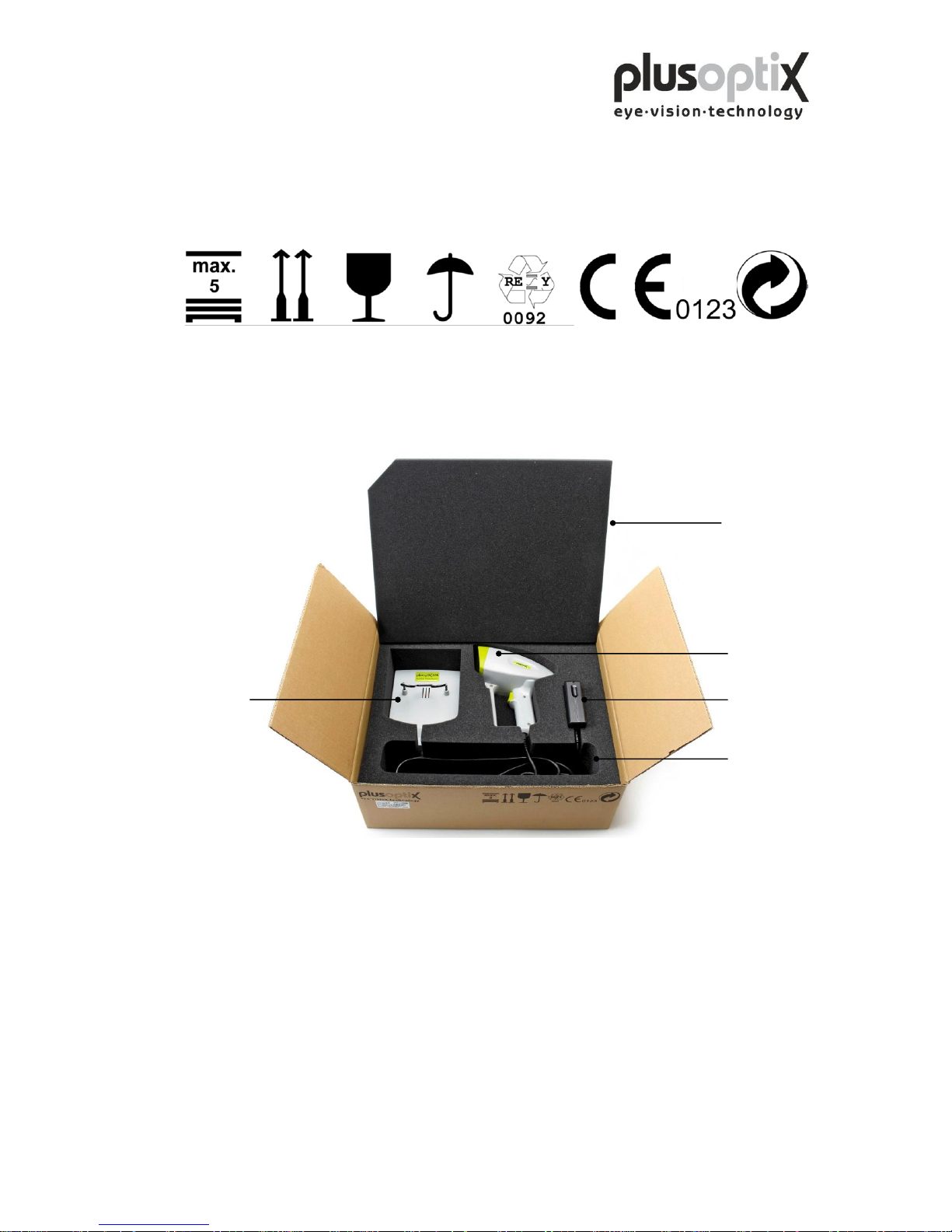
The plusoptiX A09 device is delivered in a paper carton. The following information is
printed on the carton:
Only 5
cartons on
each other
This side
up
Fragile
Keep dry
Carton
manufactorer
CE conform
Recycleable
Inside the paper carton the measuring device is placed in a preformed inset to avoid
damages to the plusoptiX A09 device during transportation.
Paper carton size: 51 cm x 41 cm x 20 cm (20 inches x 16 inches x 8 inches)
Preformed insert: Polyurethane foam (volume weight 28 kg / CBM)
Weight: 3.5 kg (7.7LB) carton including plusoptiX A09 device
In case the paper carton shows any damages which may be caused by external force
during transportation, e.g. careless loading or unloading, please do not accept the
delivery and inform the company you have purchased the device from.
Cradle
Cover
Camera
Medical power
unit
Cables
Page 7
Page 7 of 43
2.1 Storage
The plusoptiX A09 device can be stored in the original package when the storage room
fulfils the following requirements:
Temperature: 0°C to +50°C (32°F to 122°F)
Humidity: 10% to 85% (no condensation)
Keep the plusoptiX A09 device away from any heat source.
2.2 Unpacking
Open the carton only in position „This side up“.
After unpacking the plusoptiX A09 please check that all items are delivered which are
listed on the delivery note. Missing items can only be replaced when a claim has been
forwarded to the company you have purchased the device from within one week after
accepting the delivery.
Note: Please keep the original packing material in case later transportation may be
required.
Do not store the packing material in a room with an open fire place.
2.3 Setting up
When you set up the plusoptiX A09 make sure that no cable can be reached by children.
Protect the plusoptiX A09 from direct sunlight.
Page 8
Page 8 of 43
3. Connecting and switching on the system
3.1 Connection
For operation, the plusoptiX A09 must be connected to a monitor and keyboard with a
mouse. The monitor must fulfill the following system requirements:
Resolution: 1024 x 768 pixels
Interface: VGA
Four (4) USB ports of type A are available on the plusoptiX A09 for connecting e.g.
keyboard, mouse, printer or USB-sticks.
Where a monitor is already available at a workstation, a switch (monitor switch TK 207
by “Trendnet”) can be used to connect this monitor to the plusoptiX A09. This allows
you to save space by using the monitor for your practice network and for the plusoptiX
A09.
The plusoptiX A09 can also be attached to your practice network using an RJ-45
connection (network cable) via a GDT interface. Plusoptix supplies the software
required for operation via a GDT interface at no charge, should you wish to connect the
plusoptiX A09 to your network. In this case please consult your practice network
support personnel.
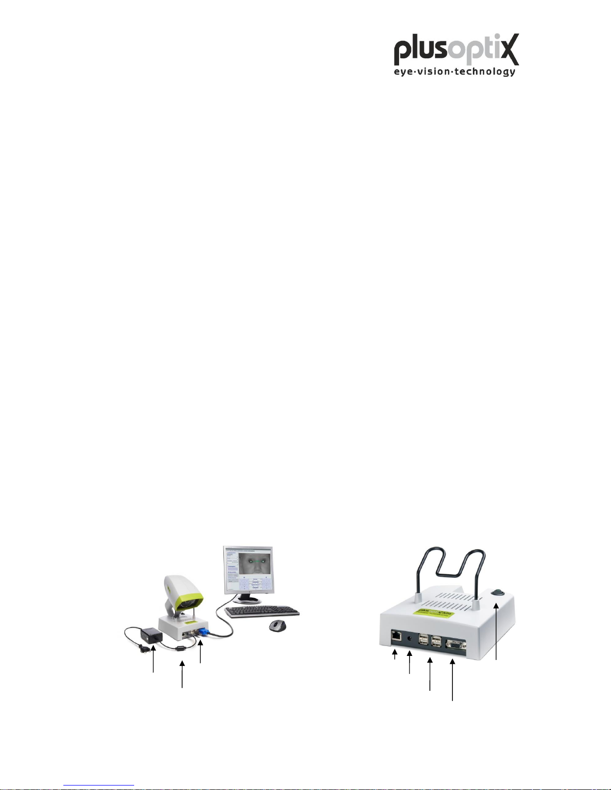
Fig. 1: Connect the VGA cable from the monitor to the plusoptiX A09. The keyboard
and mouse can be connected to the plusoptiX A09 by means of a USB cable or a
wireless USB adapter. Attach the 12V DC connector to the plusoptiX A09 and
the medical power unit to a 110 – 220 V AC (50 – 60 Hz) power plug. Ensure
that the power plug is switched off after close of business. This is a precaution in
case a short-circuit occurs during night-time which may cause a fire.
Fig. 2: Location of the connectors on the plusoptiX A09
plusoptiX A09
Fig. 1
Fig. 2
12VDC cable
medical power unit
MES 30B - 3P1J
VGA cable for
monitor
USB wireless adapter
for mouse and keyboard
on/off switch
4 x USB
VGA
RJ-45
12VDC
Page 9
Page 9 of 43
3.2 Switching on the system
Switch on the monitor before you switch on the plusoptiX A09 (see Fig. 2 on page 8 for
the on/off switch).
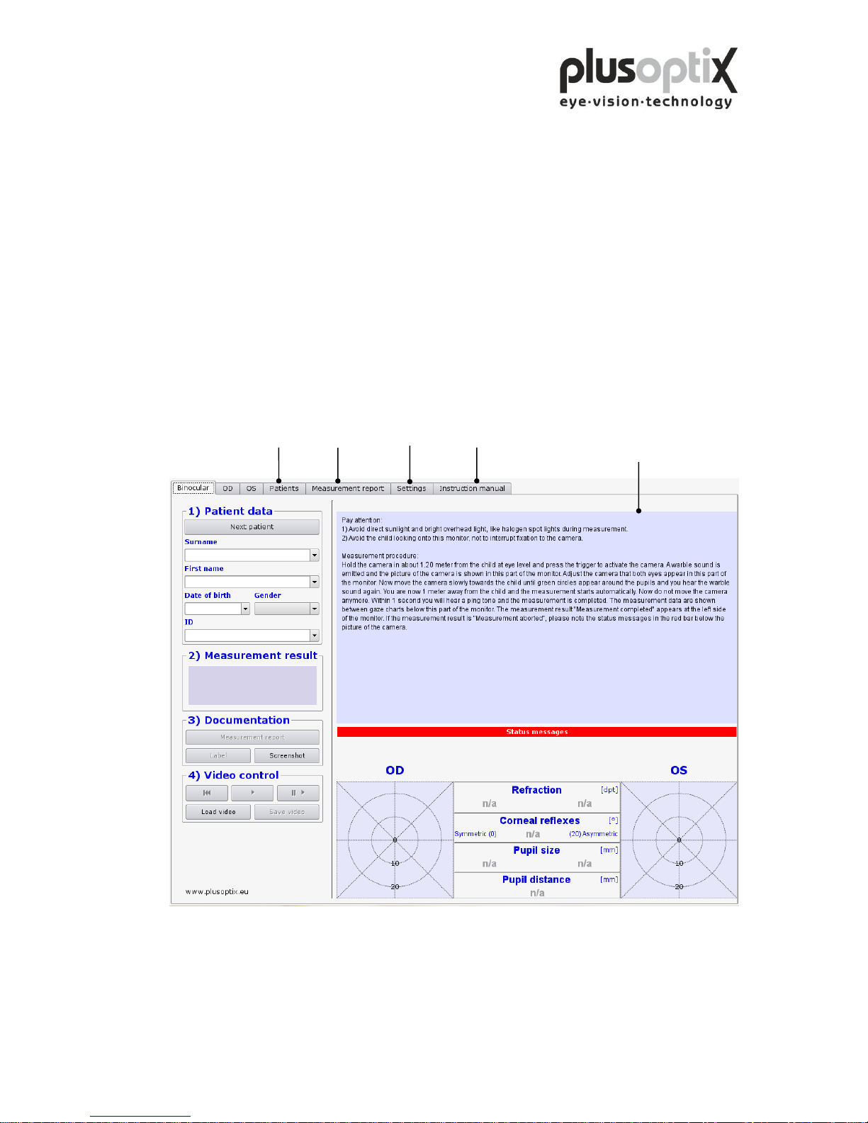
After loading the software (approx. 1.5 minutes) the “Plusoptix Start Page” appears.
You can now start measurements.
Note: When using the system for the first time, first click on “Settings” to adjust the
settings as required for operation.
Plusoptix Start Page
This brief description only
appears after the system has
been switched on.
Please make sure that no USB-stick is inserted in the plusoptiX A09 during switching
on, because it can lead to problems during booting. The USB adapters from keyboard
and mouse as well as probably connected printers are excluded from this.
Settings
Optional
License D License Z
Click here to open
Instruction manual
Page 10
Page 10 of 43
4. Settings
For the first start-up it is recommended to adapt settings e.g. general (basic settings),
printer, network (GDT), your address and system to the conditions of your practice.
With the exception of the general settings appears at each page a security query, where
you have to type in “YES”, to perform settings if you are authorized to do that. If you
are not authorized click on “Cancel”. Then you just can have a look at the existing
settings and not perform any settings.
4.1 General (Basic settings)
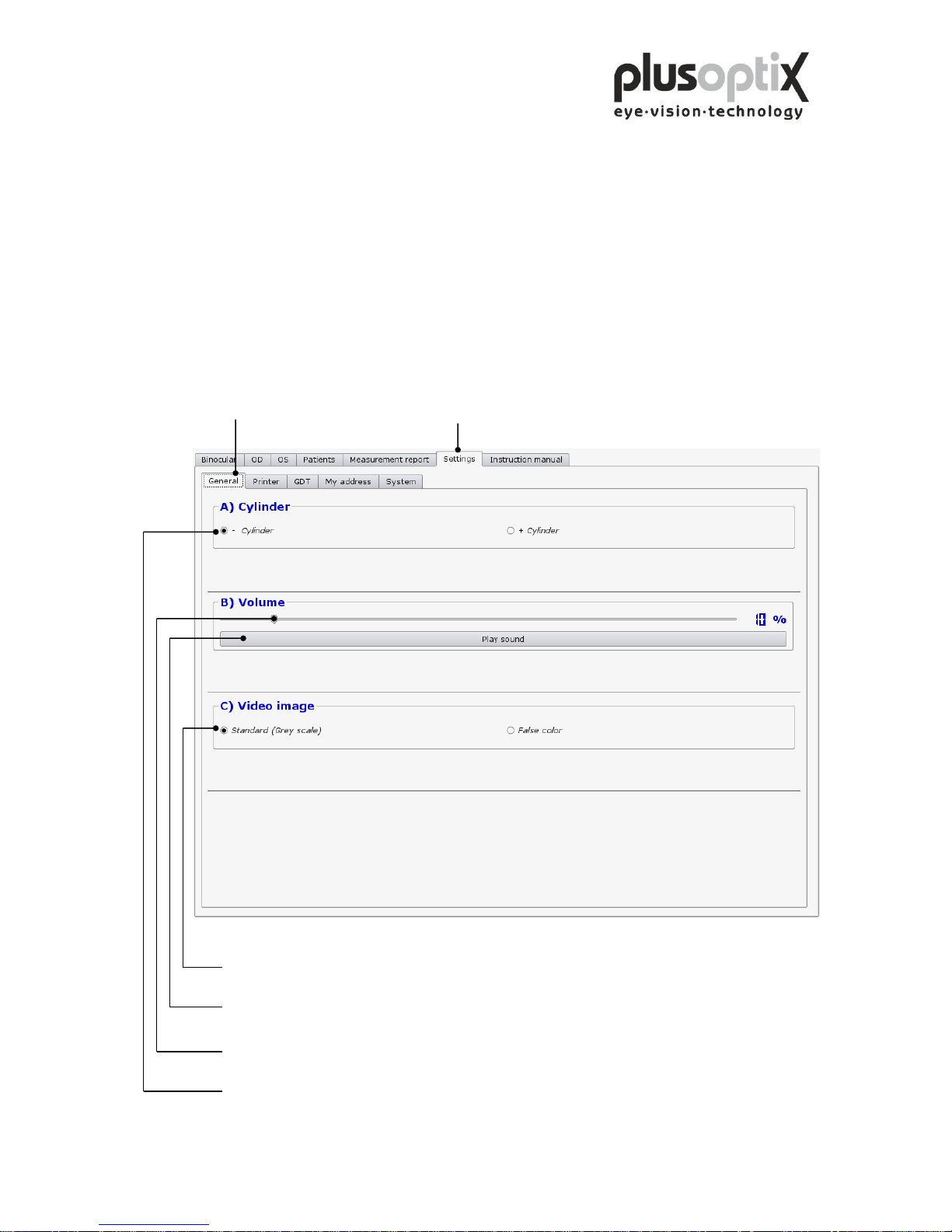
Click on “Settings” and then on
"General" to perform basic settings.
Click here to switch the video image on the monitor from black and white to false colours. You
can see the brightness profile of the pupils in colour (Brückner test).
Click here to test the volume of the warble sound.
Click here and move the slide to the left using the mouse to decrease the volume of the warble
sound, or to the right to increase the volume.
Click here to measure the astigmatism in minus cylinder or plus cylinder.
Page 11
Page 11 of 43
4.2 Installing a printer
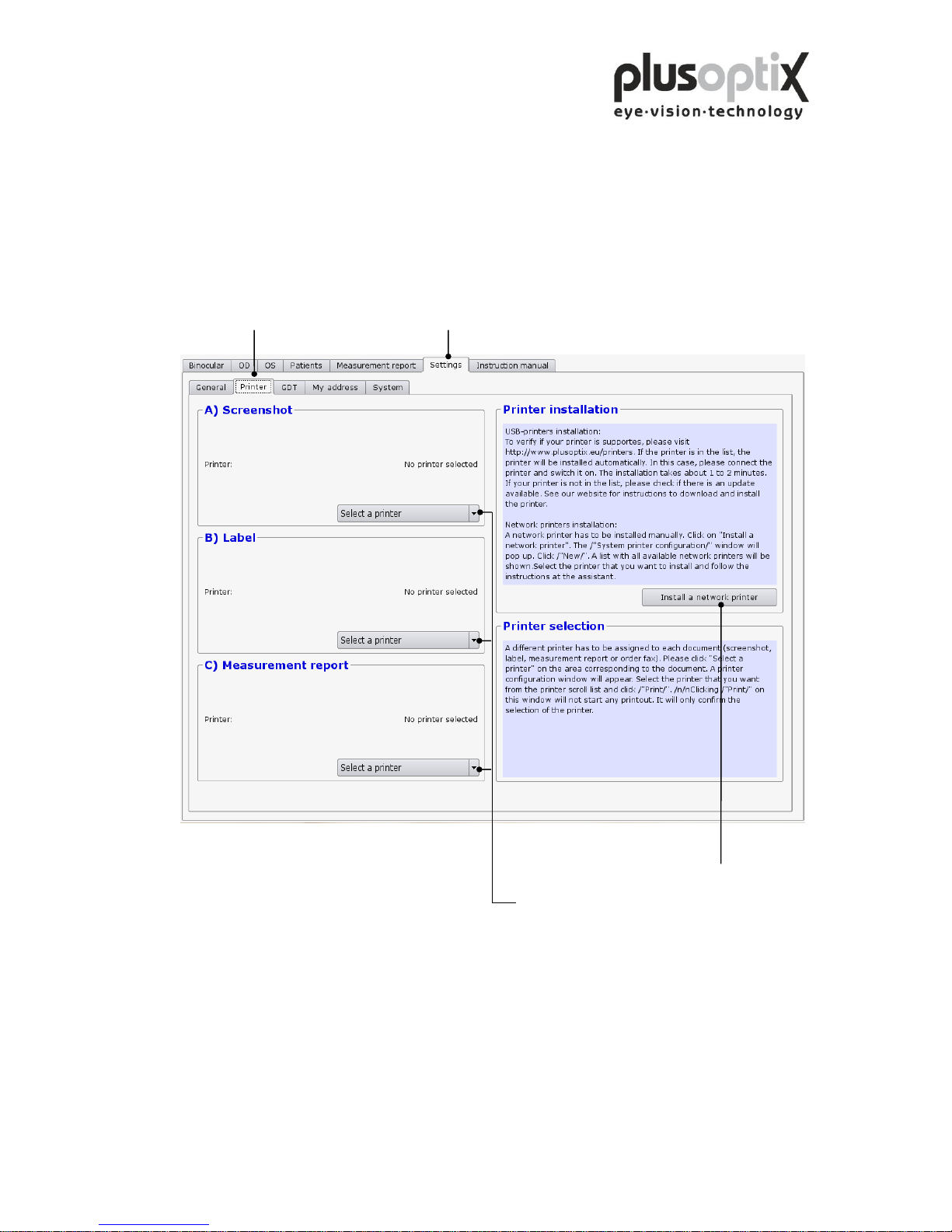
To be able to print a screenshot, a self-adhesive label for the patient paper record or a
measurement report (optional, License Z), suitable printer must be installed. You can
attach the printer to the plusoptiX A09 directly via the USB or via your practice
network.
Click on “Settings” and then on "Printer".
Click here to select the network printer.
Click here to select the printer to be used to
print the corresponding document.
A pdf-printer (“PDF”) is already installed on the plusoptiX A09.
If you select the pdf-printer, it is necessary to insert a USB stick into one of the free
USB ports on the plusoptiX A09. After a successful measurement and after clicking on
“Measurement report” or “Screenshot” the document will be saved automatically on the
stick. After about 10 seconds you can remove the stick from the device and print the
document at a computer connected to a printer.
Page 12
Page 12 of 43
4.3 Practice network
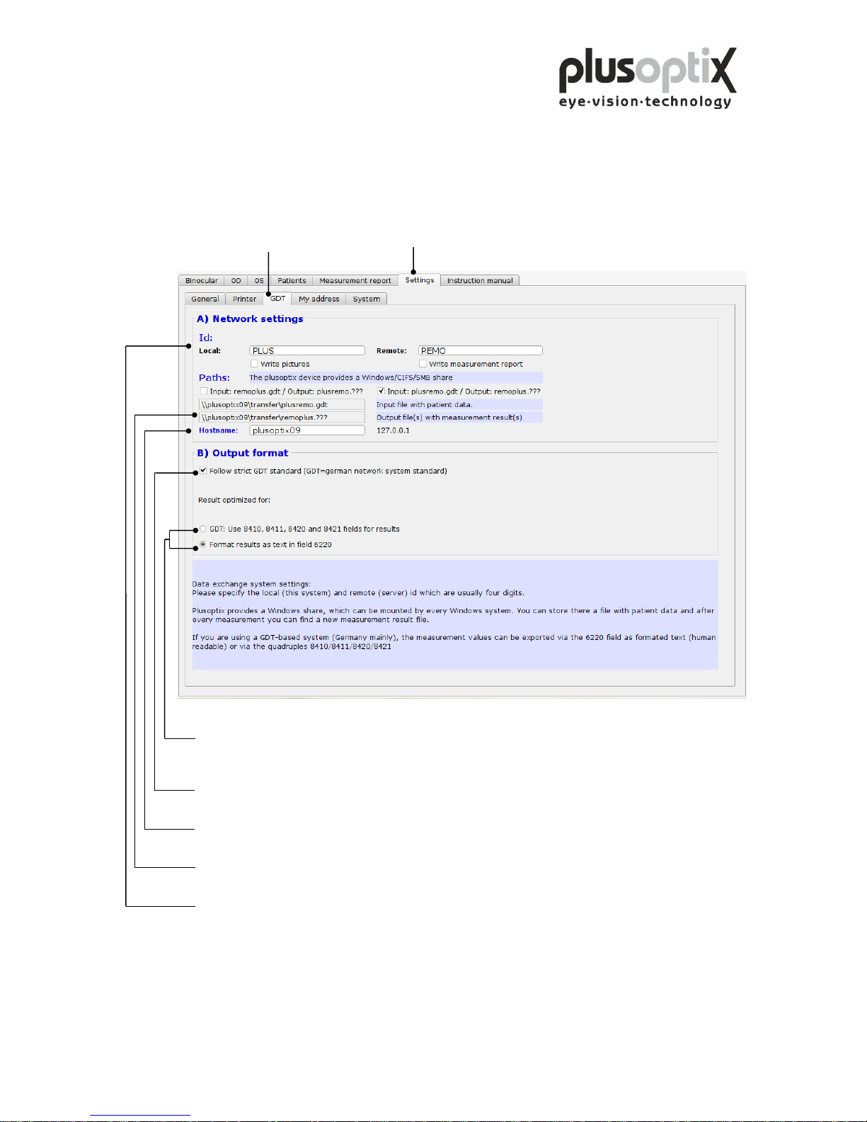
To connect the plusoptiX A09 to an existing practice network, proceed as follows:
Click on “Settings” and then on "GDT".
Output format of the measurement results in the network - Parser: output in field identifiers
- Human readable: formatted text output
Adherence to GDT standard when transmitting measurement values. A selection can be made
between formatted text and field identifiers 8410 to 8421.
Enter the name of the plusoptiX A09 in the network here.
The paths for data input to the plusoptiX A09 and for data export to the network are extracted from
this value.
Identifiers for data exchange in the practice software.
Specifications for the GDT-standard is available at: http://www.plusoptix.eu/gdt
Page 13
Page 13 of 43
4.4 My Address (License Z, optional)
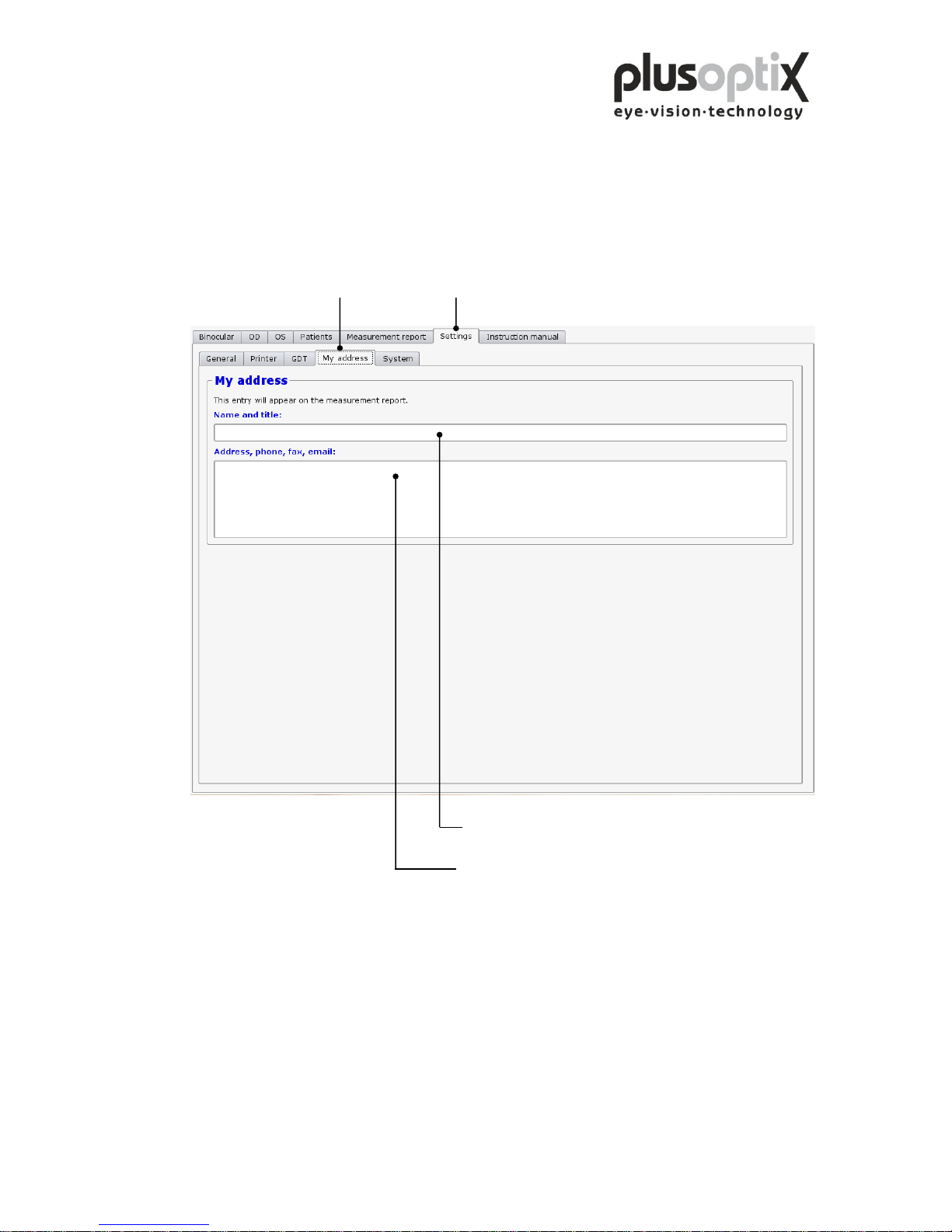
Enter the name, address, telephone, fax and email address of your practice here, to
enable the details to appear on the measurement report.
Click on “Settings” and then on "My address".
Click here to enter the name of your practice.
Click here to enter the address, telephone, fax and email
address of your practice.
Page 14
Page 14 of 43
4.5 System
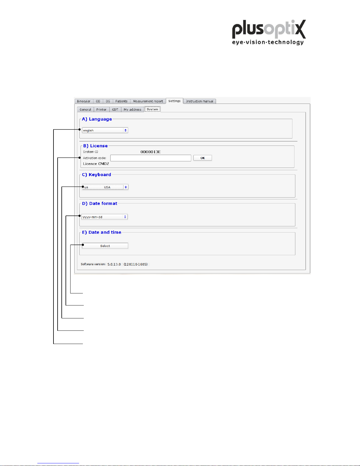
The system settings have been carried out by the company you have bought the device
from. In case you would like to change some system settings, please proceed as follows:
Click here to set the current data and time of day.
Click here to select the date format for entering the date of birth.
Click here to set the keyboard layout.
Click here to activate additional licenses.
Click here to select the language for the operator interface.
Once you have performed all system settings, click on “Binocular” to return to the start
page. You can then begin measurements.
Page 15
Page 15 of 43
5. Binocular measurement
5.1 Measurement procedure
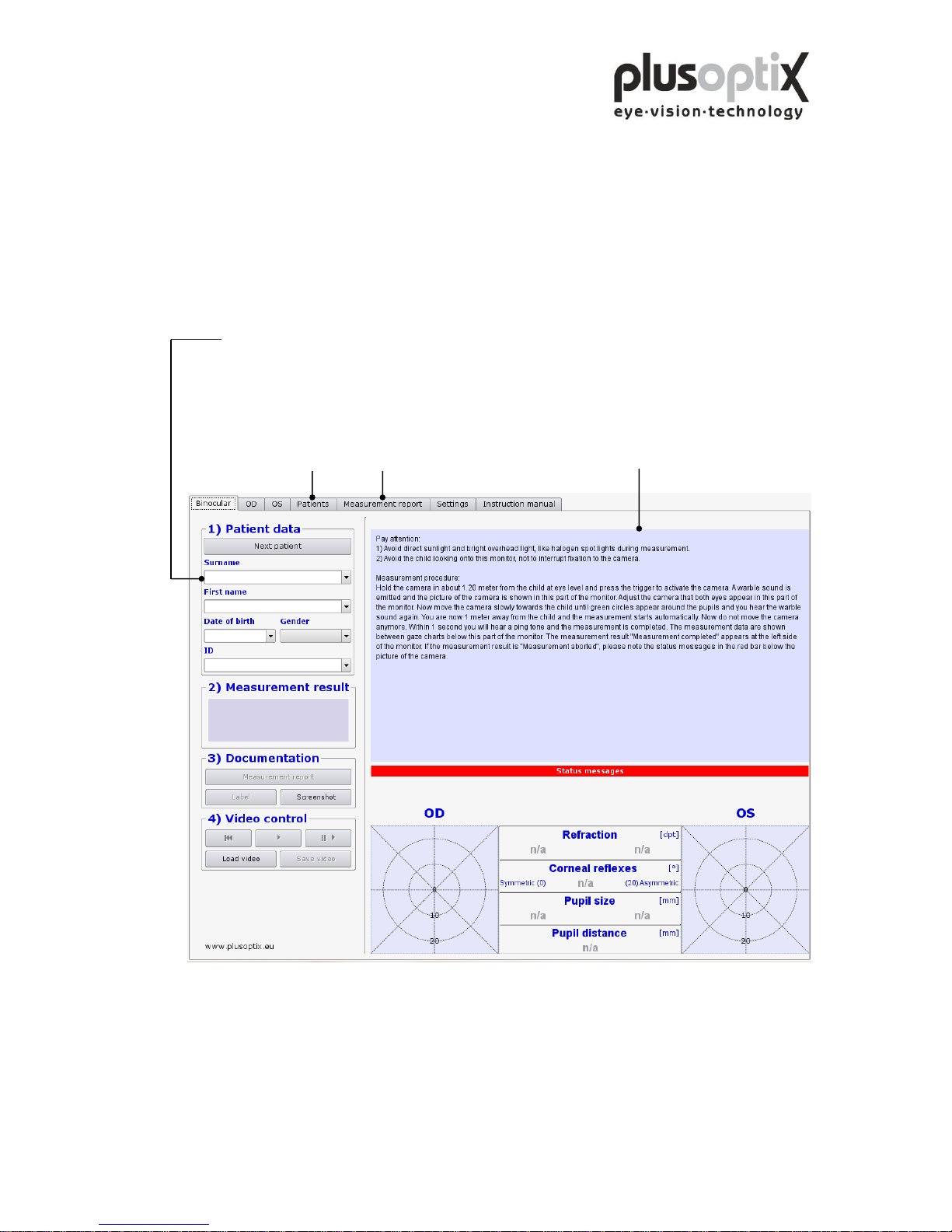
Step 1: If the plusoptiX A09 is not connected to a practice network and the
measurement results are to be documented, please enter the patient data. This
data should be entered before the child is seated for measurement.
Enter patient data. The following data are valid:
a) Patient data (Surname, first name, date of birth and gender) or
b) Patient data and ID or
c) ID and date of birth
This brief description only appears after
the system has been switched on.
Optional
License D License Z
Page 16
Page 16 of 43
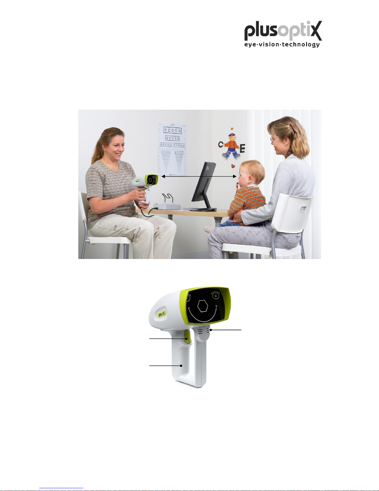
Step 2: Hold the camera approximately 1.20 metres (3.3 feet) away from the child at
eye level and start the camera by pressing once on the trigger in the handle. A
warble sound can be heard to draw the child’s attention to the camera. Avoid
the child observing the monitor. The attention span of young children is
extremely short. Consequently, distractions during measurement such as the
monitor image or other persons in the room should be avoided.
Camera
Note: You can repeat the warble sound as often as required during measurement to
attract the attention of the child to the camera once again.
1 m
(3.3 feet)
Handle
Loudspeaker
Trigger
Page 17
Page 17 of 43
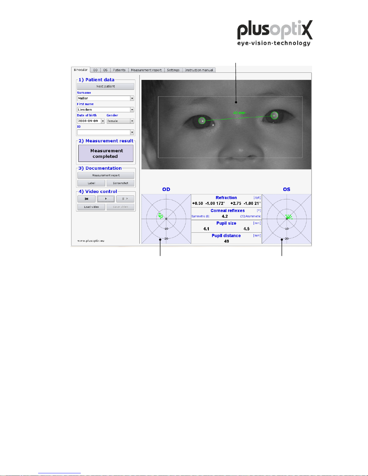
Step 3: Align the child’s eyes in the white box on the monitor.
Now move the camera slowly forwards until you can see green circles around both
pupils and you hear another warble sound. You are now 1 m from the child; the
measurement will start automatically. Do not change the distance after this point.
Within one second, a ping tone will signal the end of measurement. The measurement
values will be displayed between the gaze charts, and the measurement result
"measurement completed" appears at the left side of the screen.
Note: If the measurement result "Measurement aborted” appears, the following could be
the cause:
1. A white square around the pupil is a sign that the measurement distance of 1m ± 5cm
was not adhered to. Use a tape measure to check the distance to the child and then
start measurement again.
2. A red edge around the pupil is a sign that the pupil is too small. Reduce the light in
the room to allow the pupils to dilate and repeat the measurement.
3. If the plusoptiX A09 does not find the pupils within 20 seconds, the measurement
procedure is automatically terminated. The most common reasons for this are:
Gaze chart
right eye
Gaze chart
left eye
Page 18
Page 18 of 43
a) One or both pupils are not completely displayed on the screen, e.g. eyelashes
or the eyelid is partially occluding the pupil. The mother should lift the child’s
eyelid gently. Repeat the measurement.
b) If the corneal reflexes appear on one gaze chart as red point clouds and on the
other as green point clouds, the asymmetry of the corneal reflexes is ≥ 10
degrees. In this case, it is not possible to perform a binocular measurement.
You can however measure the eyes individually (see 6. Monocular
measurement).
c) One or both pupils show different brightness patterns. This indicates media
blurring, corneal damage, a foreign particle or other reasons.
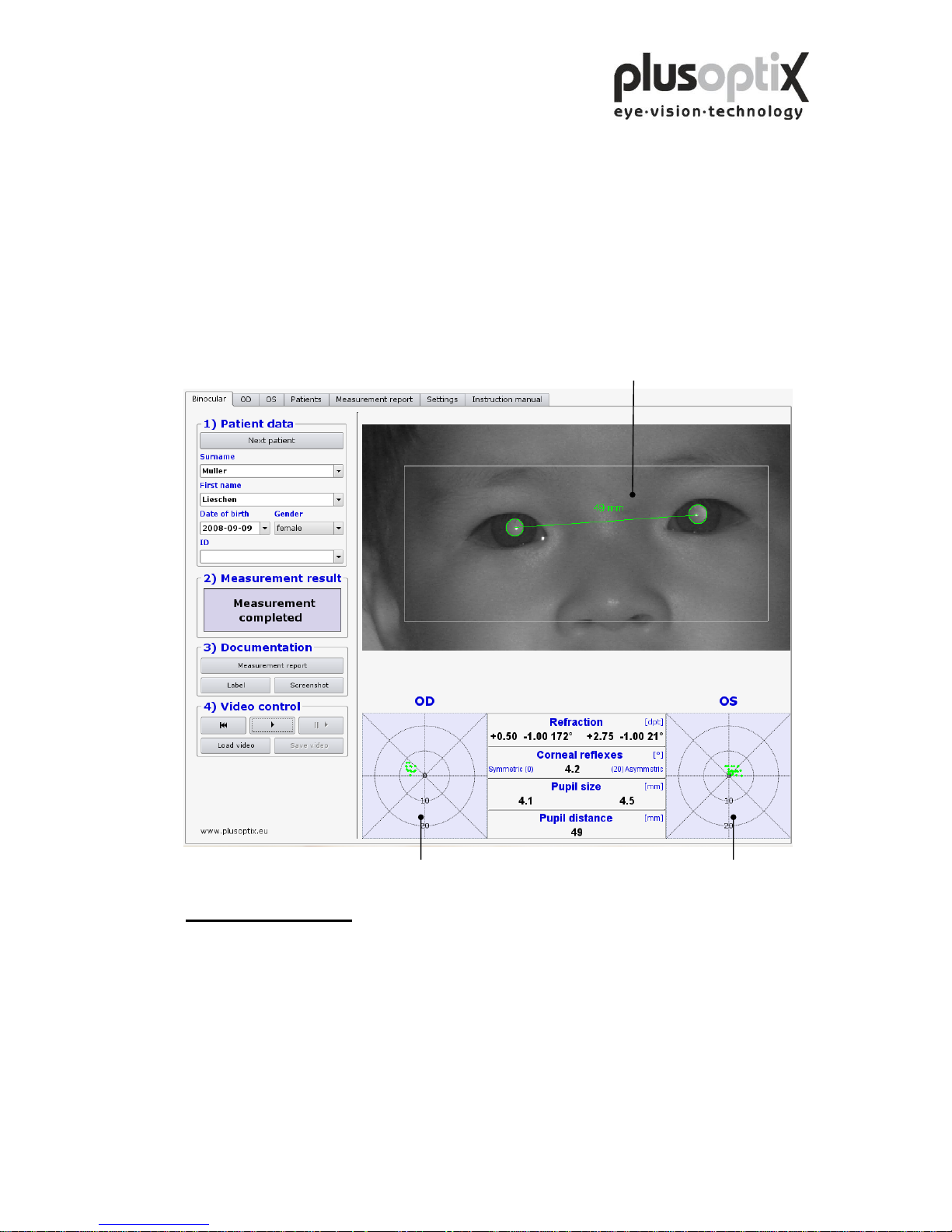
Step 4: Measurement results
Measurement results:
Refraction: - Sphere [dpt]
- Cylinder [dpt]
- Axis [º]
Corneal reflexes: Symmetry of corneal reflexes [º]
Pupil diameter: Average [mm]
Pupil distance: PD [mm]
Gaze chart: Position of corneal reflexes in relation to pupil centre [º]
Pupil distance
Gaze chart
right eye
Gaze chart
left eye
Page 19
Page 19 of 43
5.2 Documentation
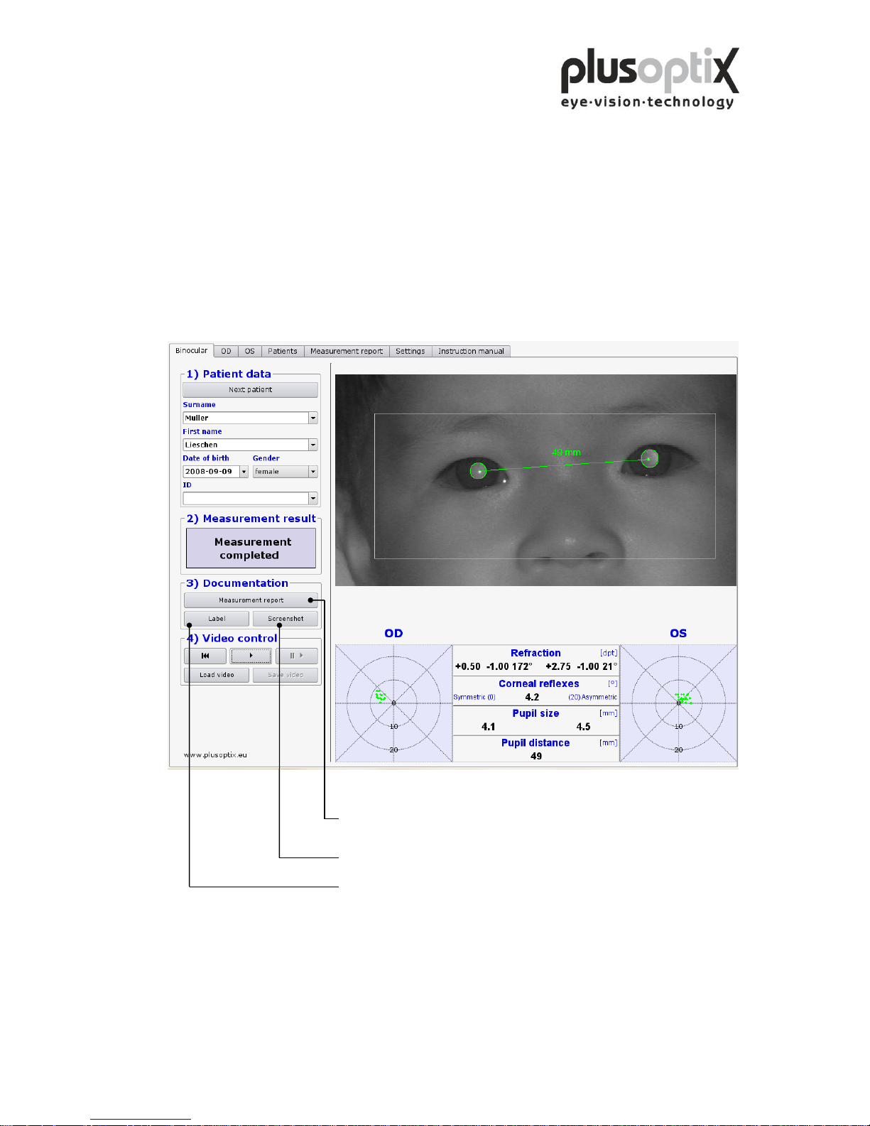
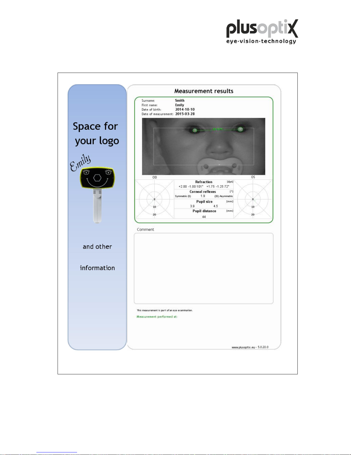
The following documents can be printed:
- Measurement report (measurement results with comments)
- Measurement results on self-adhesive label
- Screenshot
To print one of these documents later, videos must be saved to archive the data. To do
so, see chapter 5.4 Storing a video and 5.5 Loading a video.
Click here to print the measurement report with the measurement results
and your comments (optional, License Z).
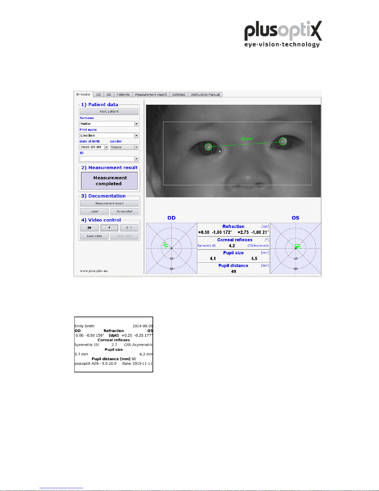
Click here to print a screenshot.
Click here to print a self-adhesive label for the patient record.
Examples of a measurement report, a screenshot and a self-adhesive label can be found
on the following pages.
Page 20
Page 20 of 43
Measurement report (A4 and letter format)
Page 21
Page 21 of 43
Screenshot
Self-adhesive label
Printer: Dymo Label Printer
Label Size 54 x 25 mm, Order no. 11352 (Europe), order no. 30336 (America)
Note: The order no. can differ in your country.
Check it on: http://sites.dymo.com/pages/CountrySelector.aspx
Page 22
Page 22 of 43
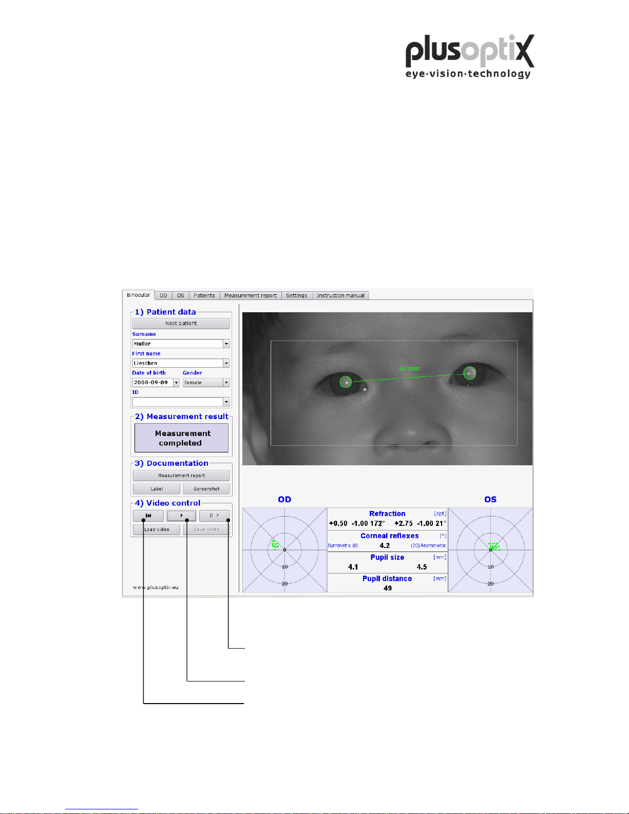
5.3 Viewing the video of the last measurement
You can view the video in individual images directly after measurement
to:
a) Detect media blurring
b) Detect strabismus in false colours
c) Trace eye movements
d) Test the infrared component in the room
To redisplay the measurements, the video must be replayed in real time again.
Click here to play back the video of the measurements in individual
images. The available measurement values from each image are
displayed on the screen.
Click here to play back the video of the measurement in real time.
Click here to rewind the video to the beginning.
Page 23
Page 23 of 43
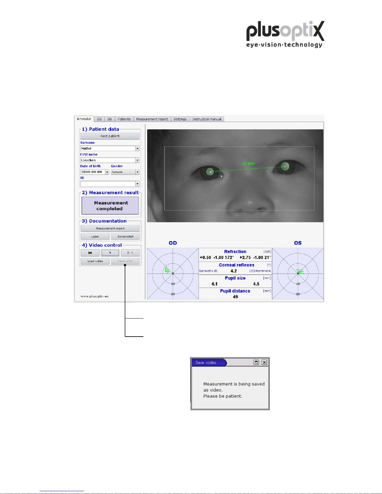
5.4 Storing a video
Videos are not stored in the plusoptiX A09, but are rather overwritten by the next
measurement. If a measurement indicates particular issues such as media blurring, the
video can be stored directly after the measurement on a USB stick or an external hard
drive with a maximum current consumption of 0.5 A. To do so, insert a USB stick into
one of the free USB ports on the plusoptiX A09 and proceed as follows:
1. Wait after insertion of the USB stick approx. 5 seconds until the
“Save video” button becomes active.
2. Now click on “Save video”. The “Save video” window appears on
the monitor. The video is automatically stored on the USB stick and
afterwards the window disappears again.
3. The “Save video” button will become active again after you perform
the next measurement.
Page 24

Page 24 of 43
Replaying of the saved videos is only possible with the plusoptiX A09 (see 5.5 Loading
a video).
Is there not enough storage space on the inserted USB-stick, following window appears:
Click on “OK” and remove this USB-stick.
Take a new, empty USB-Sick and insert it into the plusoptiX A09 and click again on
“Save video”, to save the video.
Keep the USB-stick to save the data, in case you would like to print out a document,
like a measurement report, again.
Page 25
Page 25 of 43
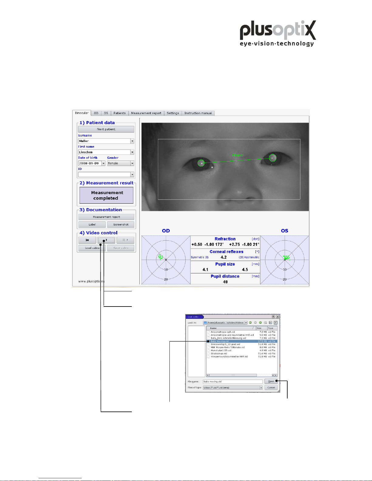
5.5 Loading video
The plusoptiX A09 allows you to load videos directly from a USB stick and to view
them. You can only play back videos that have been recorded and stored using the
plusoptiX A09. To do so, insert a USB stick or an external hard drive with a maximum
current consumption of 0.5 A into one of the free USB ports on the plusoptiX A09 and
proceed as follows:
1. Wait after insertion of the USB stick approx. 5 seconds until the “Load
video” button becomes active.
2. Now click on “Load video”. The window containing the available videos
opens.
3. Select the video that you wish to play back and click on “Open”.
4. Click here to play the loaded video.
Do you replay a stored video, documents like a measurement report or a screenshot can
be printed again.
Page 26
Page 26 of 43
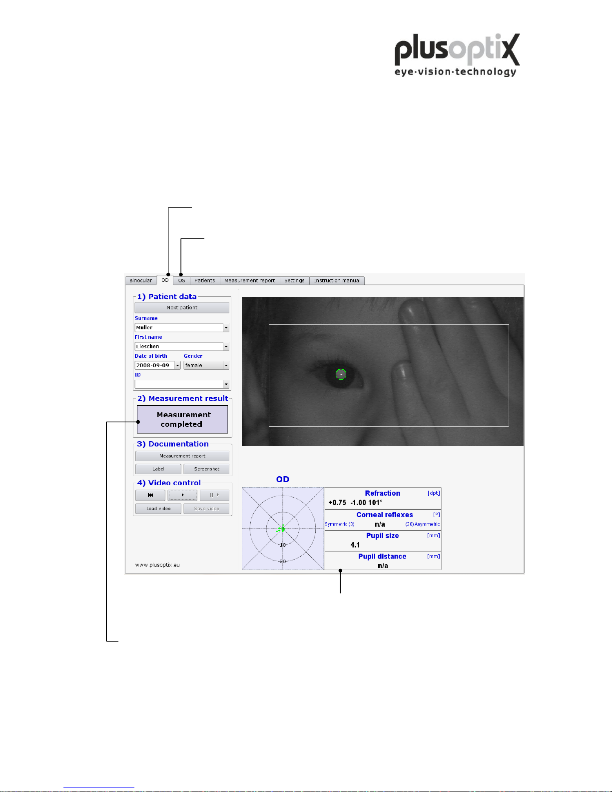
6. Monocular measurement
Patients displaying asymmetric corneal reflexes ≥ 10º cannot be measured binocularly.
The monocular measurement function “OD” and “OS” allow you to measure each eye
individually. The measurement is performed as for binocular measurement (see 5.1
Measurement).
Click here to measure the right eye.
Cover the left eye.
Click here to measure the left eye.
Cover the right eye.
Measurement results for the right eye.
Where the measurement system finds two pupils, the measurement is cancelled and
“Measurement aborted” is displayed as the measurement result. In addition, the status
message “Monocular: cover OD or OS” appears below the video image.
Page 27
Page 27 of 43
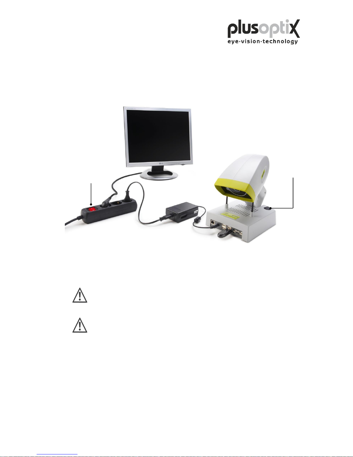
7. Switching off the system
First switch off the plusoptiX A09 using the on/off switch, followed by the monitor.
The on/off switch on the plusoptiX A09 flashes after switch-off until the program has
been shut down completely.
If you are using a multiple socket outlet make sure that it is child-proof.
At the end of business day the monitor and the medical power unit must be
separated from the power supply or you have to switch off the on/off switch
at the multiple socket outlet. This is a precaution in case a short-circuit
occurs during night-time which may cause a fire.
on/off switch
plusoptiX A09
on/off switch
multiple socket outlet
Page 28
Page 28 of 43
8. Printing the measurement report (License Z, optional)
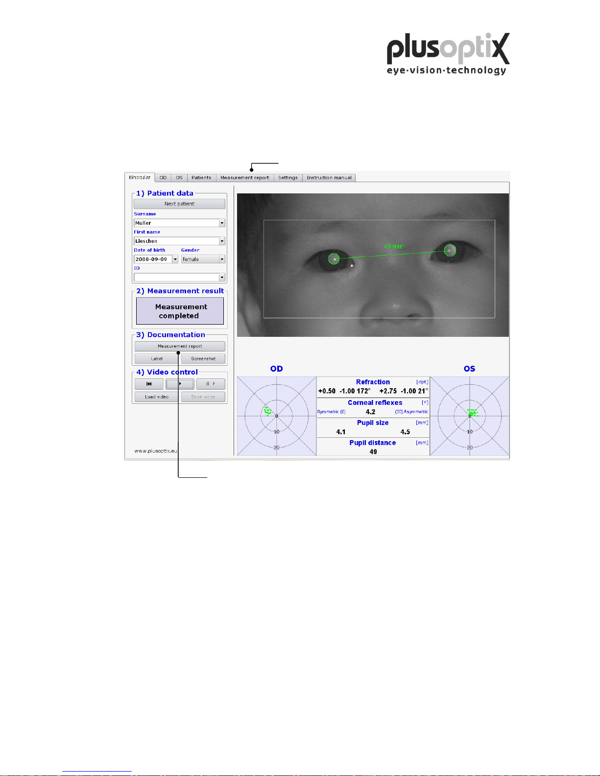
Is a printer installed and connected, the measurement results can be printed together
with your comments. The comments can be stored as freely editable text modules.
Click here to create a measurement report.
Click here to create text modules (see chapter 8.2)
Page 29
Page 29 of 43
8.1 Adding an info column
You can add a personal info column on the left side of the measurement report. To
create the info column you need a computer and a graphic software or you authorize an
illustrator to do this.
Note:
1. Create your information (text and images) with any graphic program in an exact
dimension of 3.300 x 583 pixels.
2. Store this information as an image on the supplied USB stick. The name of the image
may not contain any diacritical marks and must have a suffix of .png.
3. Switch on the plusoptiX A09 and wait until the start page appears.
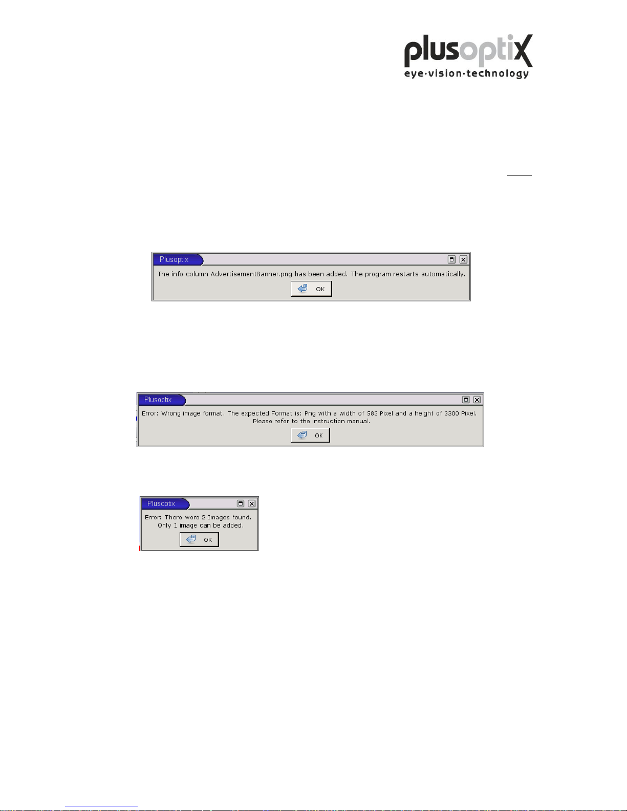
4. Insert the USB stick into the plusoptiX A09. Following window appears.
Click on “OK”. The program restarts automatically.
5. Remove the USB stick.
Following error messages can occur inserting the info column:
1.
The size of the inserted picture is not 3.300 x 583 pixels. Click on “OK” and change
the size of your picture into the requested one.
2.
Two pictures are stored on the USB stick. Click on “OK” and remove one.
Page 30
Page 30 of 43
8.2 Creating text modules
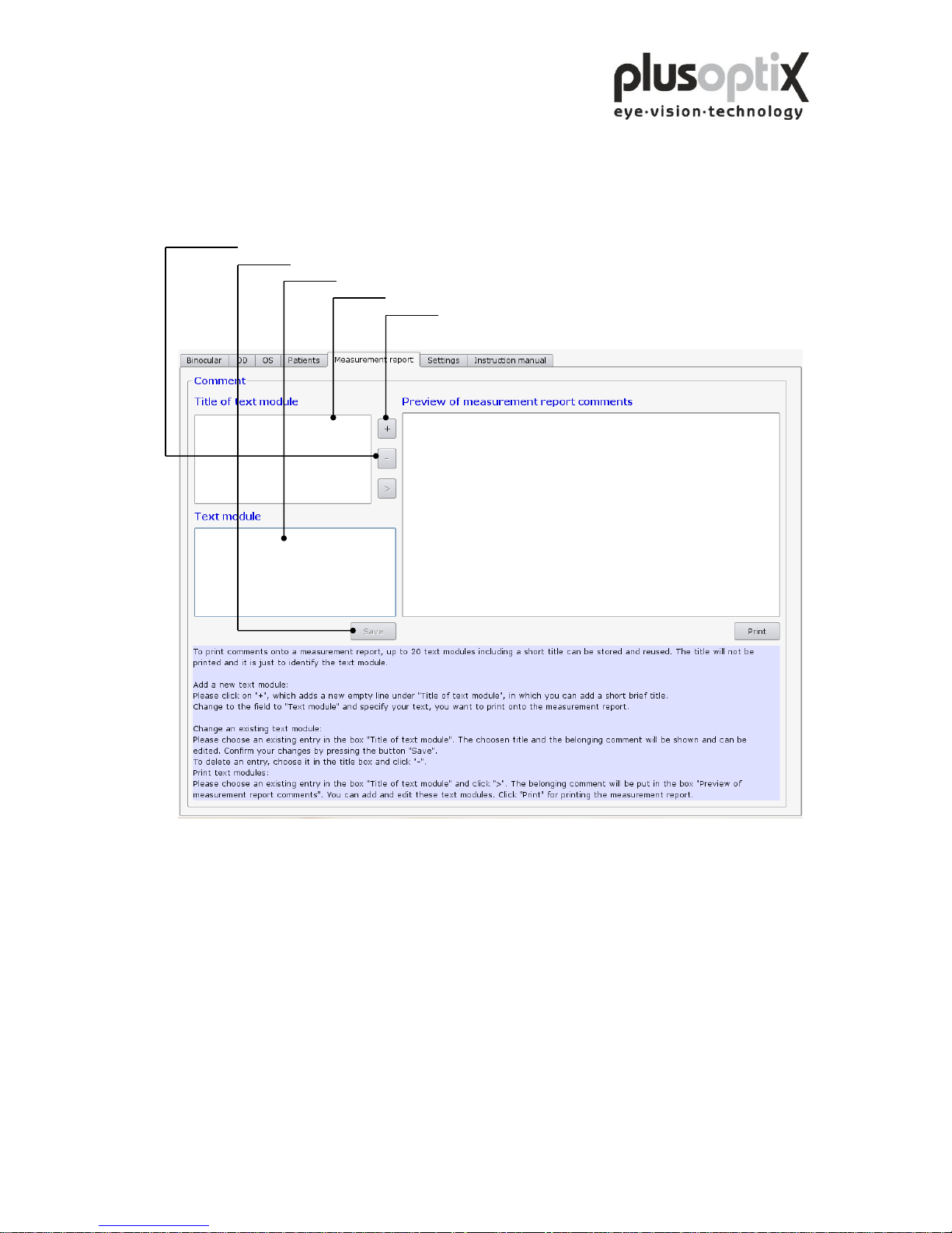
You can enter a maximum of 20 different text modules. To do so, proceed as follows:
5. Click here to delete a selected text module and the title.
4. Click here to store the text module.
3. Click here to enter the text module.
2. Click here to enter the title of a text module.
1. Click here to create a title for a new text module.
The title of the text modules is used only to call up the corresponding text module, and
is not printed with the measurement report.
Page 31
Page 31 of 43
8.3 Printing the measurement report
You can add different text modules to the measurement report as comments and edit
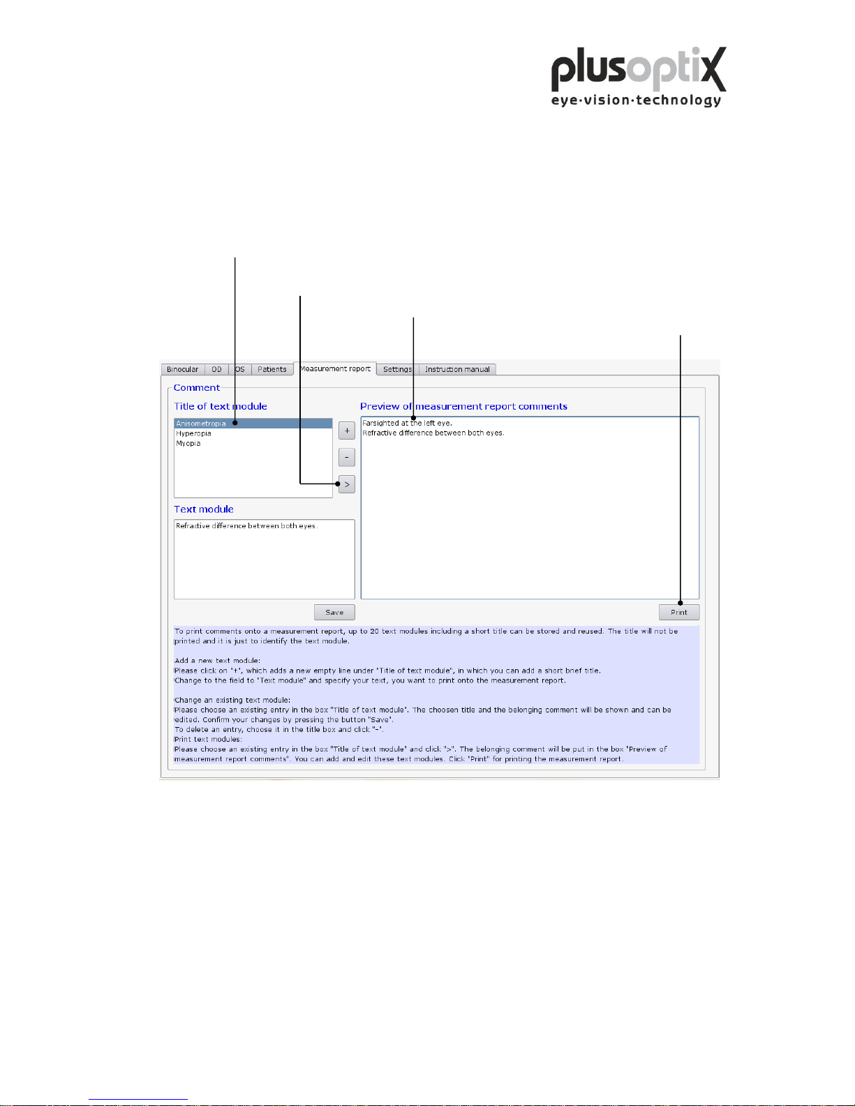
these before printing. To do so, proceed as follows:
1. Click here to select a text module to be printed on the
measurement report.
2. Click here to transfer the selected text module to the
field “Preview of measurement report comments”.
3. Click here to change the text.
4. Click here to print the measurement report with
the comments.
Page 32
Page 32 of 43
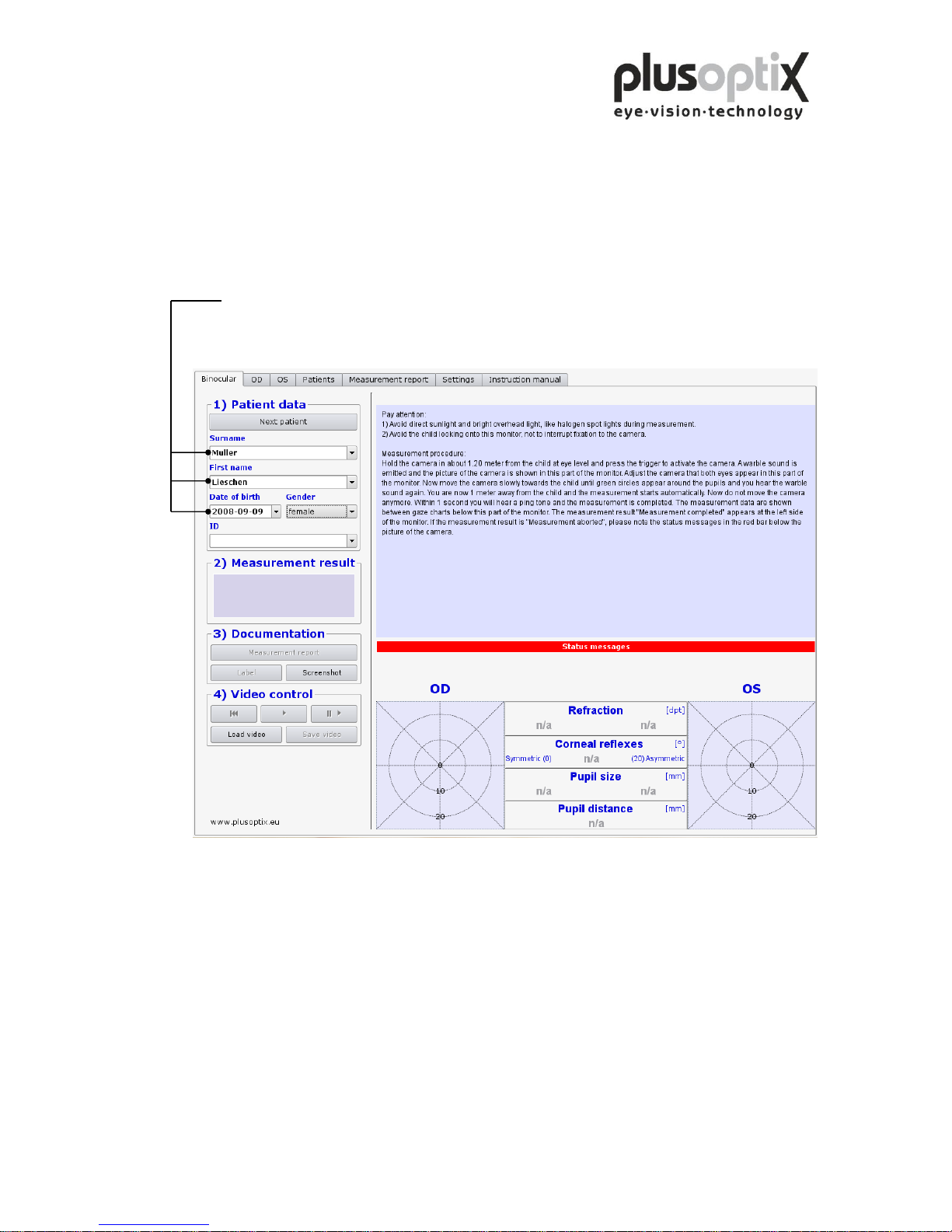
9. Patient database (License D, optional)
The patient database is an alternative to a practice network. You can use the database to
store patient data and measurement results, and to compare measurement results with
previous ones.
9.1 Entering patient data
Enter patient data. The following data are valid:
a) Patient data (Surname, first name, date of birth and gender) or
b) Patient data and ID or
c) ID and date of birth
To add a new patient to the database, enter the patient data in its entirety and then
perform the measurement. The measurement values will be automatically stored
together with the patient data.
If you enter two “John Smith” records with the same date of birth, the ID (patient
number or medical insurance number) must also be entered to allow for differentiation.
Note:
- Before measuring a new patient, please do not omit to delete the patient data entered
using the key “Next patient” and to enter the data for the new patient or to search the
date with the scroll key.
- To select an existing patient, enter the first letter of the patients’ name in the surname
box (e.g. “S” for Smith). All patients’ names beginning with this letter will appear
and you can scroll for your patient. The more letters you enter, the faster your
search will be (e.g. “Smi”).
Page 33
Page 33 of 43
9.2 Measurement data
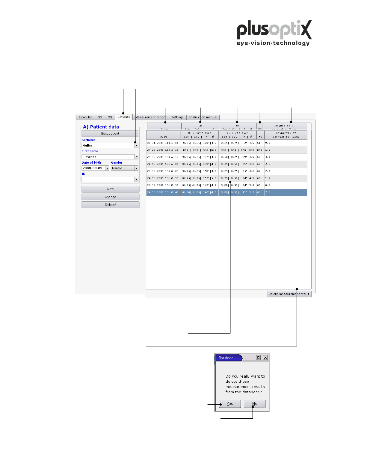
Click on “Patients” and enter the entire patient data or scroll down to the patient to have
a look at these existing measurement data. The data are listed chronologically.
Date of Measurement data Measurement data Asymmetry of
measurement right eye left eye corneal reflexes
If you would like to delete measurement data,
proceed as follows:
1. Click on the line you would like to delete.
The line will be marked blue.
2. Then click on “Delete!”.
Afterwards a window with a
security query will appear.
3. Click on “Yes” and the marked line will be deleted.
If you would like to cancel this procedure, click on “No”.
Pupil distance
Page 34
Page 34 of 43
9.3 Deleting or modifying patient data
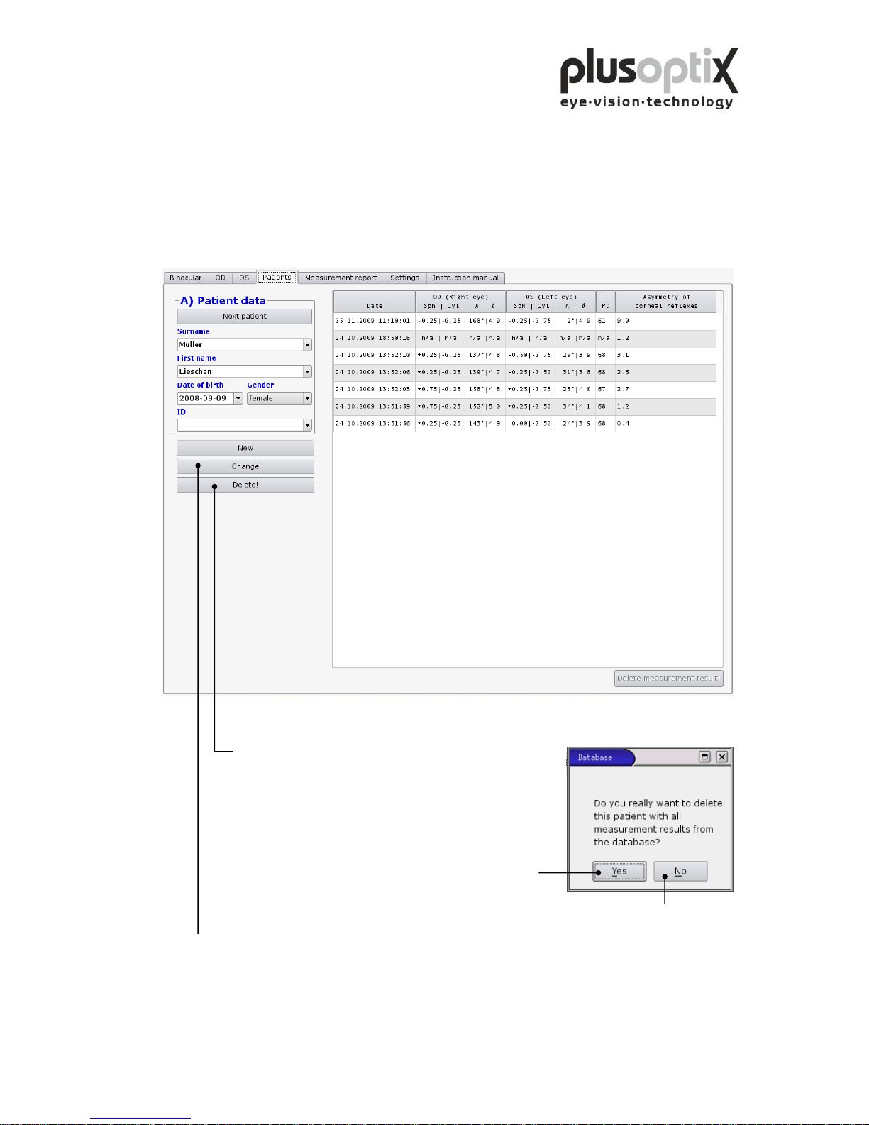
To delete a patient record from the database, i.e. this patient data including
measurement results, proceed as follows:
1. Call up the patient to be modified.
2. Click here to delete the selected patient data record.
Afterwards a window with a
security query will appear.
3. Click on “Yes” and the patient data will be deleted.
4. If you would like to cancel this procedure, click on “No”.
5. To modify the patient data record, click on “Change” and a new window will appear
“B) Edit patient data”.
Page 35
Page 35 of 43
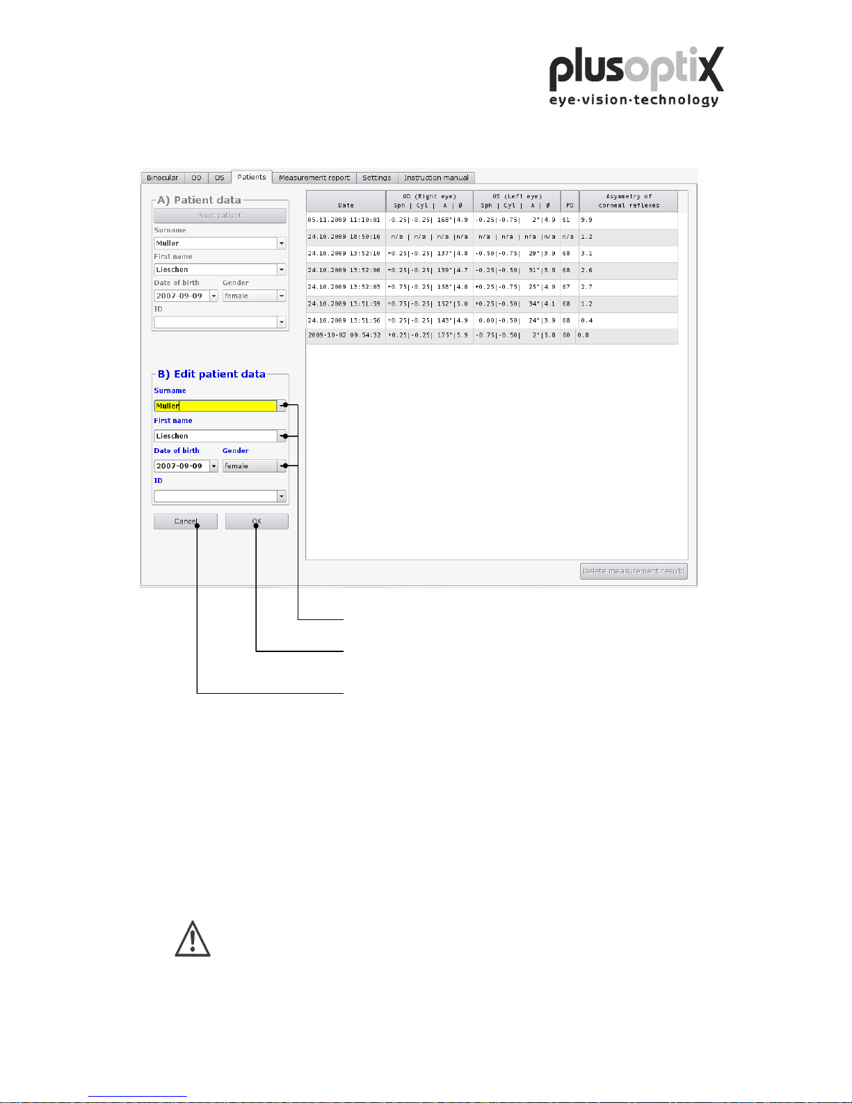
The following page describes how you can modify the patient data record.
1. Click here to perform changes.
2. Click here to store changes.
Click here to cancel the procedure.
9.4 Backing up measurement results
The system provides an option to back up the measurements on a regular basis. To do
so, insert the supplied USB stick into a free USB port on the plusoptiX A09. The data is
automatically saved on the stick. The space available on the stick is sufficient to store
about 10 years’ worth of data.
Please ensure that you remove the USB stick from the plusoptiX A09 after
the back up, as this could lead to problems at boot time.
Page 36

Page 36 of 43
10. Warranty
The plusoptiX A09 is supplied with a 12-month guarantee, starting from the data of the
delivery note.
All work processes at Plusoptix are included in a quality management system, thus
providing the highest degree of assurance of error-free materials and workmanship.
Should the plusoptiX A09 fail during the guarantee period or the method of operation
not be in accordance with the operating instructions, Plusoptix will repair or exchange
the system at no charge.
The guarantee is only supplied on new systems that have been sold by Plusoptix or an
authorized sales partner of Plusoptix. Systems requiring repair can be returned to the
authorized sales partner from whom the system was purchased. Before you return the
device, please consider the advices in chapter 12.2 Trouble shooting. The customer is
responsible for the transport costs of the system.
Note: A copy of the system delivery note must be included in the transport to ensure the
validity of the guarantee claim.
The guarantee will not be provided on systems that have been damaged externally, and
will be void in its entirety in the event of improper use, cleaning and transport as well as
changes or intervention to the software and usage of the plusoptiX A09 contrary to the
instructions. Claims under guarantee will also be void if the system is opened by
persons not authorized by Plusoptix.
Note: Software updates during the guarantee period are supplied at no charge.
Page 37

Page 37 of 43
11. Service and maintenance
11.1 Service
For repairs or guarantee services, please send the plusoptiX A09 system in its original
packaging to the company you have bought the device from or to:
Plusoptix GmbH
Service
Neumeyerstr. 46
90411 Nuernberg
Germany
Tel.: +49 - 911 - 598 399 - 20
Fax: +49 - 911 - 598 399 - 90
Plusoptix Inc.
2850 Paces Ferry Road
Suite 440
Atlanta, GA 30339
USA
Tel.: +1 – 800 – 488 - 6436
Note:
- The customer has to bare the transport cost for returning for repair to the company the
device was purchased from or to Plusoptix.
- A copy of the delivery note must be attached to the transport for repair in order to
prove the validity of the guarantee claim.
11.2 Maintenance
The plusoptiX A09 is maintenance-free. It is recommended that the system be covered
with a cloth when not being used. Use only a lightly moist microfibre cloth to clean the
system.
1. Do not use sprays, alcohol or other liquids to clean the plusoptiX A09.
2. Please use only a lightly moist microfibre cloth with a little cleaning
liquid to clean the front panel of the system.
Page 38
Page 38 of 43
12. Practical tips
12.1 Measurement results
The major benefit of the plusoptiX A09 is that binocular measurements in miosis in
children can be performed from a distance of one meter. Device accommodation is
therefore unnecessary, and the measurement is non-stressful for the child, the parent and
the examiner. A value of 1.00 dpt is taken into consideration for accommodation in the
measurement, at a distance of 1 meter.
1. Myopia and astigmatism
Neither myopia nor astigmatism is influenced by accommodation. Consequently,
these measurement values have a tolerance of ± 0.50 dpt in 80% of cases and a
tolerance of max. ± 1.00 dpt in the remaining 20% of cases, in comparison to
retinoscopy in mydriasis.
2. Anisometropia
Regardless of the accommodation status, an anisometropia can be detected with
certainty, as both eyes are measured simultaneously (binocular).
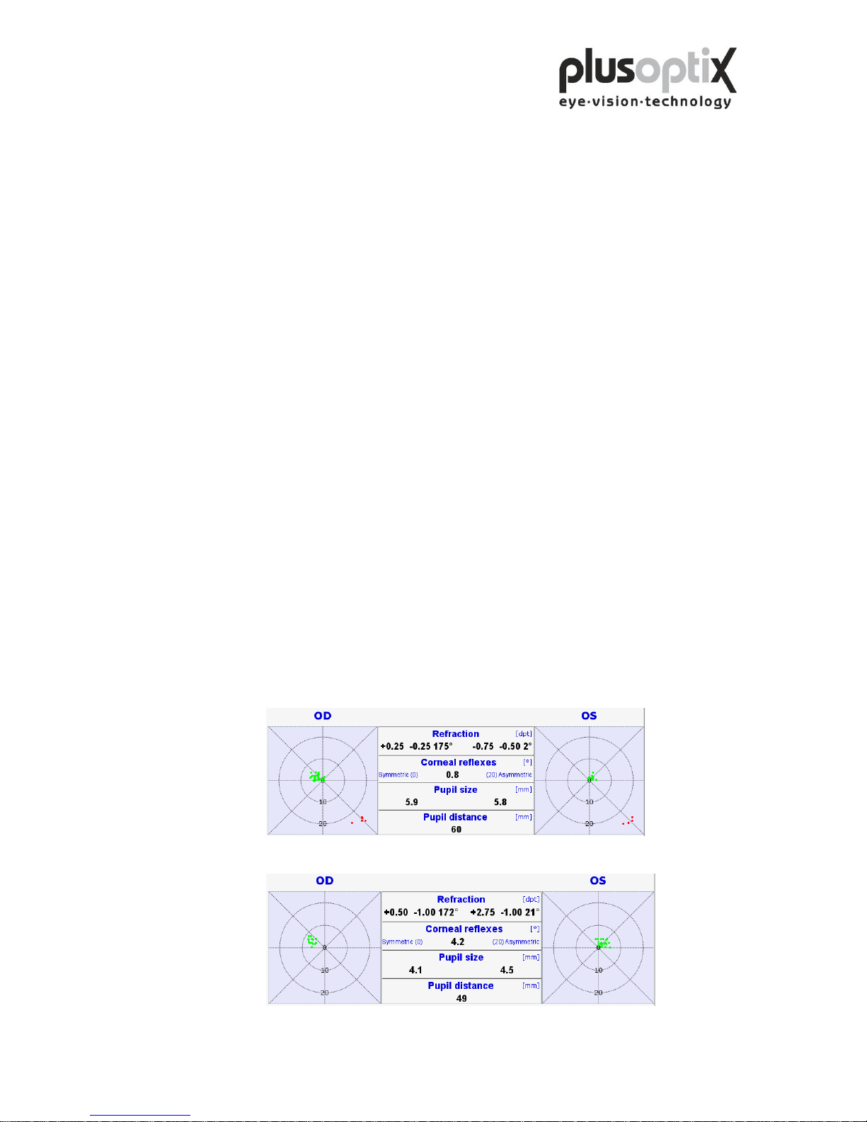
3. Small-angle squint
During every measurement, the corneal reflex for both eyes is displayed
simultaneously. Where the corneal reflexes are asymmetric, the possibility exists that
the child has a squint (Fig. 2). In the case of infants however, asymmetric corneal
reflexes can also be measured by a fixation that is not yet fully developed. Due to the
camera resolution and the measurement distance, asymmetries of less than 2 degrees
cannot be reliably detected.
Fig. 2: Asymmetric corneal reflexes
Fig. 1: Symmetric corneal reflexes
Page 39
Page 39 of 43
4. Hyperopia
A hyperopia can be either totally or partially compensated for by means of
accommodation. As a result, a measurement in miosis does not provide exact values,
respectively an existing hyperopia can be considerably underestimated. Regardless of
this, a higher hyperopia can however possibly be detected in children older than 2
years by means of a measurement using +3.00 dpt lenses.
Examples:
1st measurement value
without lenses
2nd measurement
value
with +3.00 dpt lenses
Explanation
+0.75 dpt
+0.75 dpt
Accommodation of 3.00 dpt or more during the
first measurement; the child has a hyperopia of
+3.75 dpt or more.
0.00 dpt
-1.00 dpt
Accommodation of at least 2.00 dpt during the
first measurement; the child has a hyperopia of at
least +2.00 dpt.
Measurement using +3.00 dpt lenses is not possible in children under two years of
age These children can also be measured in cycloplegia with the plusoptiX A09, as
the pupils are generally not larger than 8 mm. Note that 1.00 dpt must be subtracted
from the spherical measurement values, as a value of 1.00 dpt is included in the
measurement values for accommodation in miosis, at a distance of 1 metre.
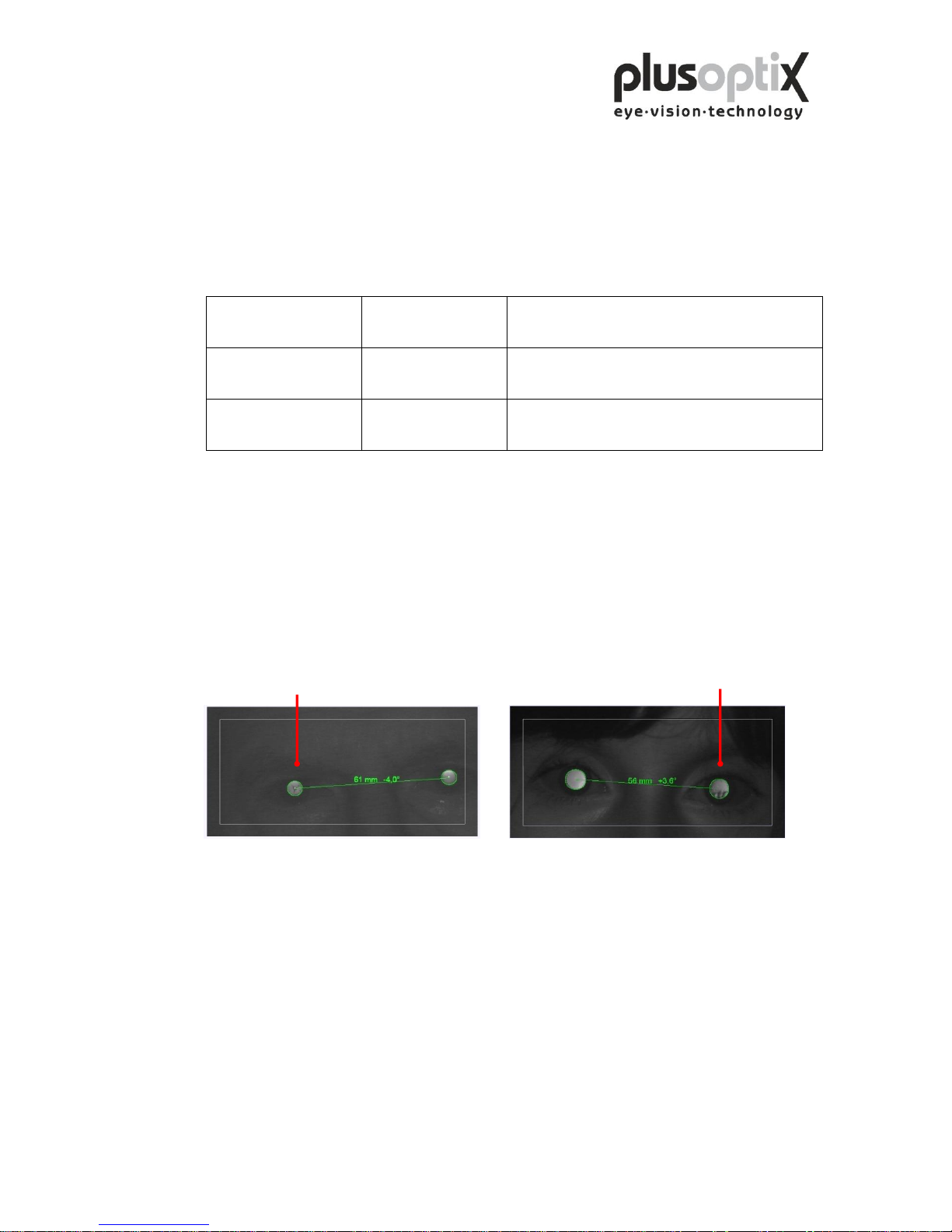
5. Media blurring
Where different brightness structures or black dots are detected in the pupils, media
blurring, a foreign particle or corneal damage is indicated. The following images
show clear cataract-like structures.
6. Nystagmus
The plusoptiX A09 can be used to measure nystagmus in children in most cases, as
the determination of refraction is performed at 50 Hz, i.e. every measurement is
performed at 20 ms.
7. Anisocoria
An anisocoria can be detected, as the plusoptiX A09 also indicates the pupil diameter
of both eyes.
Page 40
Page 40 of 43
8. Measurement range
The measurement range of the plusoptiX A09 is between -7.00 dpt and +5.00 dpt and
is based on the spherical equivalent of the measurement result. This measurement
range can be extended by a max. ± 3.00 dpt by using flippers with plus or minus
lenses.
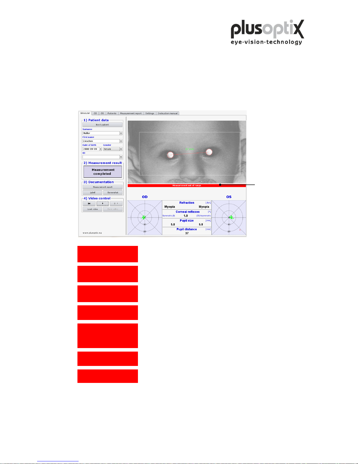
9. Status messages
Pupils not found
The plusoptiX A09 was unable to find pupils within 20 seconds. Restart the
measurement procedure and ensure the correct distance to patient.
Pupil too large
One or both pupils are larger than 8.00 mm. Increase the lighting in the room to
contract the pupils.
Pupil too small
One or both pupils are smaller than 4.00 mm. Decrease the lighting in the room to
dilate the pupils.
Infrared noise
Infrared component in ambient light is too strong. Avoid direct sunlight and
switch off “warm” light sources such as halogen or incandescent lamps.
Measurement out of range
If the spherical equivalent is ≥ +5.00 dpt the measurement value shows
“Hyperopia”. The child is very far-sighted. If the spherical equivalent is ≥ -7.00
dpt the measurement value shows “Myopia”. The child is very short-sighted. In
both cases please refer the child to an eye specialist.
Monocular:Cover OS!
In monocular mode, only one eye can be measured. Cover the patient’s left eye.
Monocular: Cover OD!
In monocular mode, only one eye can be measured. Cover the patient’s right eye.
Status messages
Page 41

Page 41 of 43
12.2 Troubleshooting
1. The monitor does not work
Check whether the power cable is connected to the power socket and whether it is
switched on. Check also whether the monitor is connected and is switched on.
2. The plusoptiX A09 does not work.
If the green control lamp on the on/off switch on the plusoptiX A09 casing does not
illuminate, check that the medical power unit is connected to the power socket and
the 12 V outlet with the plusoptiX A09, and that the on/off switch is in the “on”
position.
3. The program no longer responds
If the program no longer responds to commands, switch off the plusoptiX A09 at the
on/off switch. Wait for 10 seconds until the switch is no longer flashing and then
switch on the system again. The software is then rebooted, and the plusoptiX A09
will be ready for operation within approx. 1.5 minutes.
4. The monitor is switched on after the plusoptiX A09
The plusoptiX A09 does not boot completely. Switch off again the plusoptiX A09 at
the on/off switch. Wait for approx. 10 seconds until the switch is no longer flashing.
Afterwards switch on the monitor and then the plusoptiX A09.
5. The message “Boot error” appears on the monitor after switching on the plusoptiX A09
The plusoptiX A09 does not boot completely. Switch off again the plusoptiX A09 at
the on/off switch. Check whether there is a flash drive or a printer with a card reader
inserted into one of the 4 USB connectors. A connected USB flash drive and these
types of printers are likely to disturb booting the device properly.
Page 42

Page 42 of 43
13. Specifications
Measurements
Refraction
binocular and monocular
Spherical range
+5.00/-7.00 dpt in 0.25 dpt steps ± 0.25dpt
Cylindrical range
+5.00/-7.00 dpt in 0.25 dpt steps ± 0.25dpt
Axis
1-180° in 1° steps ± 15°
Pupil size
4.0 – 8.0 mm in 0.1 mm steps ± 10%
Pupil distance
mm in 1.0 mm steps ± 10 %
Time per measurement
0.02 s
Measuring distance
1 m ( ± 5 cm)
Fixation target
Warble sound
Measurement principal
binocular, dynamic photosciascopy
Interfaces and standards
Interfaces
1 x VGA, 4 x USB and 1 x RJ-45
Printers
Linux compatible
Standards
EN 60601-1
Power
Medical Power Adapter
MES30B-3P1J
in 110-240VAC (50 - 60Hz), 0.8A
out 12VDC 2.5A
plusoptiX A09 power
consumption:
12VDC, 1A max.
Environmental requirements
Temperature
operating
10 to 35 °C (50 to 92 °F)
storage
0 to 50 °C (32 to 122 °F)
Humidity
operating
20 - 80 % not condensing
storage
10 - 85 % not condensing
Packaging
Size of carton
51 x 41 x 20 cm (20 x 16 x 8 inches)
Weight
A09 device
2.2 Kg (4.9 LB)
Carton
1.3 Kg (2.6 LB)
Total
3.5 Kg (7.7 LB)
Page 43

Page 43 of 43
Guidance and manufacturer´s declaration – electromagnetic emissions/
immunity
The plusoptiX A09 is intended for use in the electromagnetic environment specified below.
The customer or the user of the equipment should assure that it is in such an environment.
Emissions Test
Compliance
Electromagnetic environment - guidance
RF Emission CISPR 11
Group 1
The plusoptiX A09 uses RF Energy only for its internal function. Therefore,
its RF emissions are very low and are not likely to cause any interference in
nearby electronic equipment.
RF Emission CISPR 11
Class B
The plusoptiX A09 system is suitable for use in all establishments, including
domestic establishments and those directly connected to the public low
Voltage power supply network that supplies buildings used for domestic
purposes.
Harmonic emissions
IEC 61000-3-2
Class B
Voltage fluctuations/ flicker emissions IEC
61000-3-3
Class B
Immunity test
IEC 60601 test level
Compliance level
Electromagnetic environment –
Guidance
ESD IEC 61000-4-2
± 6 kV contact
± 8 kV air
± 6 kV contact
± 8 kV air
Floors should be wood, concrete or ceramic
tile. If floors are covered with synthetic
material the relative humidity should be at
least 30 %
Electric fast transient/burst
IEC 61000-4-4
± 2 kV for power supply
lines
± 2 kV for power supply
lines
Mains power supply should be that of a
typical commercial or hospital environment
Surge
IEC 61000-4-5
± 1 kV differential mode
± 2 kV common mode
± 1 kV differential mode
± 2 kV common mode
Mains power supply should be that of a
typical commercial or hospital environment
Voltage Dips, short interruptions and
voltage variations on power supply
input lines IEC 61000-4-11
0% 0.5 periods 0°
40% 5 periods 0°
70% 25 periods 0°
0% 250 periods 0°
0% 0.5 periods 0°
40% 5 periods 0°
70% 25 periods 0°
0% 250 periods 0°
Mains power supply should be that of a
typical commercial or hospital environment
Power Frequency (50/60 Hz) magnetic
field IEC 61000-4-8
3 A/m
3 A/m
Power frequency magnetic fields should be
at levels characteristic of a typical location
in a typical commercial or hospital
environment.
 Loading...