

Page 1

USER’S MANUAL
UP-880
English
PLUS
Page 2
IMPORTANT SAFETY INFORMATION
Precautions
Please read this manual carefully before using your PLUS UP-880 Data Projector and keep the manual handy for future
reference.
Your serial number is located next to the main power switch on the back of your UP-880. Record it here:
CAUTION
TO PREVENT SHOCK, DO NOT OPEN THE CABINET. NO USER-SERVICEABLE PARTS INSIDE.
REFER SERVICING TO QUALIFIED PLUS SERVICE PERSONNEL.
WARNING
TO PREVENT FIRE OR SHOCK, DO NOT EXPOSE THIS UNIT TO RAIN OR MOISTURE. DO
NOT USE THIS UNIT’S GROUNDED PLUG
WITH AN EXTENSION CORD OR IN AN OUTLET UNLESS ALL THREE PRONGS CAN BE
FULLY INSERTED. DO NOT OPEN THE CABINET. THERE ARE HIGH-VOLTAGE COMPONENTS INSIDE. ALL SERVICING MUST BE
DONE BY QUALIFIED PLUS SERVICE PERSONNEL.
DOC Compliance Notice
This Class A digital apparatus meets all requirements of the Canadian Interference-Causing Equipment Regulations.
Important Safeguards
RF Interference
WARNING
The Federal Communications Commission does not allow
any modifications or changes to the unit EXCEPT those
specified by PLUS Technologies in this manual. Failure to
comply with this government regulation could void your
right to operate this equipment.
This equipment has been tested and found to comply with
the limits for a Class A digital device, pursuant to Part 15 of
the FCC Rules. These limits are designed to provide reasonable protection against harmful interference in a commercial installation. This equipment generates, uses and
can radiate radio frequency energy and, if not installed and
used in accordance with the instructions, may cause harmful interference to radio communications. Operation of this
equipment in a residential area is likely to cause harmful
interference in which case the user will be required to
correct the interference at their own expense.
These safety instructions are to ensure the long life of your Data projector and to prevent fire and shock. Please read them carefully and heed
all warnings.
Installation
• For best results, use your Data projector in a darkened room.
• Place the projector on a flat, level surface in a dry area away from
dust and moisture.
• Do not place your Data projector in direct sunlight, near heaters
or heat radiating appliances.
• Exposure to direct sunlight, smoke or steam can harm internal
components.
• Handle your Data projector carefully. Dropping or jarring can
damage internal components.
• Do not place heavy objects on top of the Data projector.
• If installing the Data projector in the ceiling:
– The ceiling must be strong enough to support the Data projec-
tor and the installation must be in accordance with any local
building codes.
– The Data projector must be installed by qualified PLUS ser-
vice personnel.
Power Supply
• The Data projector is designed to operate on a power supply of
100 to 120 or 220 to 240 V 50/60 Hz AC. Ensure that your power
supply fits this requirement before attempting to use your Data
projector.
• Handle the power cable carefully and avoid excessive bending. A
damaged cord can cause electric shock or fire.
• If the Data projector is not to be used for an extended period of
time, disconnect the plug from the power outlet.
Cleaning
• Unplug the Data projector before cleaning.
• Clean the cabinet periodically with a damp cloth. If heavily
soiled, use a mild detergent. Never use strong detergents or
solvents such as alcohol or thinner.
• Use a blower or lens paper to clean the lens, and be careful not to
scratch or mar the lens.
E – 2
Page 3

Table of contents
Lamp Replacement
• Be sure to replace the lamp when the Status light comes on. If you
continue to use the lamp after 1000 hours of use, the lamp will
turn off.
• Allow
a minimum of one minute to elapse between turning the
lamp off and on. High voltage is applied to the lamp immediately
when the power is turned on. Therefore turning the power of f and
quickly back on may shorten the life of your lamp and result in
damage to your Data projector.
Fire and Shock Precautions
• Ensure that there is sufficient ventilation and that vents are
unobstructed to prevent the buildup of heat inside your Data
projector. Allow at least 10cm (3 inches) of space between your
Data projector and a wall.
• Prevent foreign objects such as paper clips and bits of paper from
falling into your Data projector. Do not attempt to retrieve any
objects that might fall into your projector. Do not insert an y metal
objects such as a wire or screwdriver into your Data pr ojector. If
something should fall into your projector, disconnect it immediately and have the object removed by a qualified PLUS service
person.
• Do not place any liquids on top of your Data projector.
• Do not look into the lens while the projector is on. Serious
damage to your eyes could result.
Carrying around
When carrying this device around, please use the carrying case that
comes with it and to protect the lens from scratches, always attach
the lens cap. Also, do not subject the pr ojector main unit to strong
mechanical shock.
IMPORTANT SAFETY INFORMATION ................................... 2
Table of contents ........................................................................... 3
Basic information and preparations........ 4
About your UP-880....................................................................... 4
Checking the supplied accessories ............................................... 4
Preparing the remote control ........................................................ 5
Parts and controls .......................................................................... 6
Installation..................................................................................... 9
Connections ............................................ 11
Connecting video equipment ...................................................... 11
Connecting a PC or Macintosh................................................... 12
Using the remote control as a computer mouse
–Wireless mouse function........................................................... 14
Additional connections ............................................................... 15
Operation ................................................. 16
Using the Data Projector............................................................. 16
Various functions while using the Data Projector...................... 19
Menu operation....................................... 21
Basic operation (Selecting the input source).............................. 21
Menu structure ............................................................................ 22
Selecting the projection type ...................................................... 24
Selecting a display language....................................................... 24
Adjusting the volume .................................................................. 24
Selecting the background............................................................ 24
Setting “INPUT MODE” to “YCbCr” ....................................... 24
Adjusting the image from the source connected to the RGB IN
connector ..................................................................................... 25
Adjusting the picture elements ................................................... 27
Selecting the picture type ........................................................... 28
Selecting the wide screen display............................................... 28
Activating the power saving function......................................... 28
Quick starting the unit ................................................................ 28
Activating the on-screen function ............................................... 29
Checking hours of lamp use ....................................................... 29
Resetting all to the factory settings ............................................ 29
Others ....................................................... 30
Troubleshooting .......................................................................... 30
When the STATUS indicator lights or blinks............................. 31
Replacing the lamp housing ....................................................... 32
Specifications .............................................................................. 33
E – 3
Page 4
Basic information and preparations
About your UP-880 Checking the supplied
Congratulations On Your Purchase Of The UP-880
Data Projector
The UP-880 is one of the very best Data projectors available today .
The UP-880 enables you to project precise images up to 300 inches
across (measured diagonally) from your PC or Macintosh computer
(desktop or notebook), VCR, document camera, laser disc player,
DVD player, etc.
The Data Projector can be placed on a tabletop or cart, or permanently mounted on the ceiling*. You may use the Data Projector to
project images from behind the screen. The supplied remote control
can be used as wireless control and with the supplied mouse
receiver to operate the mouse functions on your PC or Macintosh.
* Installing the UP-880 Data Projector on the ceiling must be done by
authorized PLUS technicians. Consult your dealer for more information.
The features you’ll enjoy
• Compatible with following various color systems:
– NTSC (U.S. and Canada standard)
– PAL (Western Europe standard)
– SECAM (France and Eastern Europe standard)
– NTSC4.43 (Middle East country standard)
• Superior brightness of 800 ANSI lumens with A4 siz e and 4.5
kilograms
The DMD and our own optical design interact in a geometric
effect to increase the light usage efficiency. Now y ou can reproduce the 3 basic colors (RGB) required for color reproduction on
a single DMD. That means superior brightness, smaller size and
lighter weight.
• Sharp, clear images
There is no RGB color separation, and the spaces between the
individual pixels are not noticeable. That means sharp and clear
reproduction of small characters and figures. Take a closer look
and notice the difference in quality!
• Outstanding beauty when reproducing DVDs and other high
picture-quality information sources
Faithful gray scale reproduction makes for more natural image
displays. DVD and other high quality image sources bring out the
true display capacity of the Data Projector.
• Screen not distorted to a trapezoid (keystoning) when projecting to the height of the line of vision
Because the projection position is already set to the height of the
line of vision, there is no distortion of the screen to a trapezoid.
• Fully compatible with true SVGA; support for XGA using
advanced intelligent compression technology
The advanced intelligent compression technology of the UP-880
enables it to present clear compression XGA images without any
line omission.
• The remote control can be used to operate your PC or
Macintosh when the supplied remote mouse receiver is connected
• The compact and easy to carry cabinet with its contemporary
design complements any office, board room, or auditorium.
Make sure your box contains everything listed below. If any pieces
and packing materials if you ever need to ship your UP-880 Data
The number of accessories is indicated in brackets.
For remote control
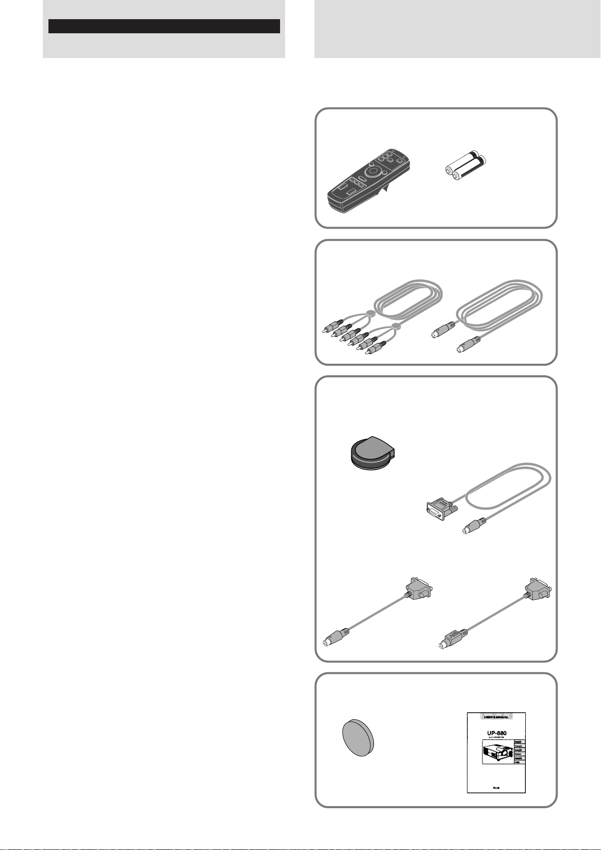
Remote control [1] Batteries (size AA/R6) [2]
For video equipment connection
Audio video cable (2m) [1]
S-video cable (2m) [1]
When using the remote control as computer
mouse
Remote mouse receiver [1]
Serial mouse cable [1]
Mouse adapter
(for IBM PS/2) [1]
Lens cap (attached to
the lens of the unit) [1]
Mouse adapter
(for Macintosh) [1]
USER’S MANUAL (this
manual) [1]
E – 4
Page 5
Preparing the
accessories
are missing, contact your dealer. Please sa ve the orig inal box
Projector.
For computer connection
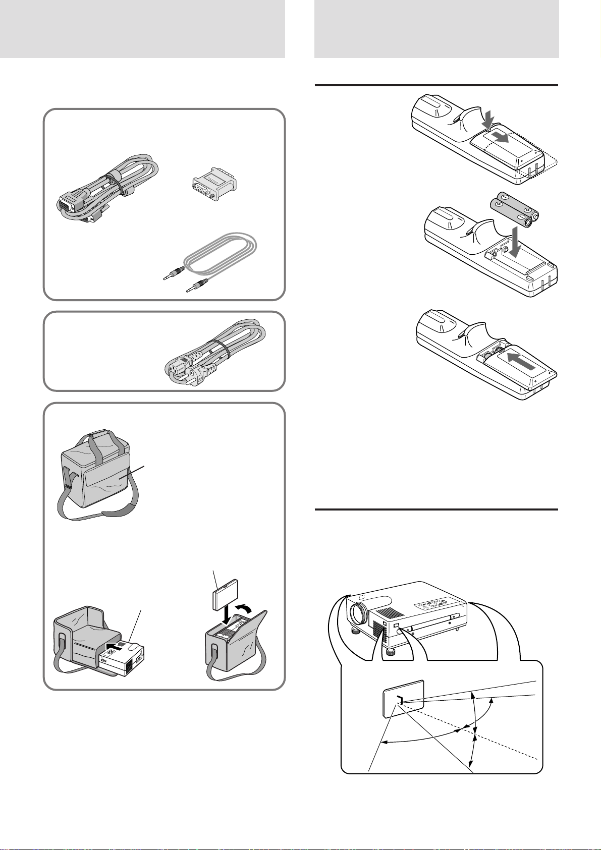
PC/Macintosh multicable
(2m) [1]
Power cable (mains lead)
(4m) [1]
Monitor adapter
(for Macintosh) [1]
PC audio cable (2m) [1]
remote control
Inserting the batteries
1 Press firmly
and slide the
battery cover
off.
2 Insert the sup-
plied two batteries (size AA/R6).
Ensure that the
polarities (+ and
–) of the batteries
are aligned correctly.
3 Slip the cover
back over the
batteries until it
snaps into
place.
Carrying case [1]
Accessory pocket
How to use the carrying case
The top of the unit
should face this side.
Notebook computer
and accessories
Notes
• If the remote control gets wet, wipe it dry immediately.
• Avoid excessive heat and humidity.
• If you will not be using the remote control for a long time, remove the
batteries.
• Do not mix new and old or different types of batteries.
• There are operations that can only be carried out by remote control.
Handle the remote control carefully.
Remote control effective range
Each side of the unit has a remote sensor as illustrated below.
The controllable range is 50 degrees horizontally and 30 degrees
vertically relative to a line that is at a right angle to the remote
sensor. And the distance between the point of the remote control
and remote sensor must be shorter than four meters.
E – 5
50˚
30˚
30˚
50˚
Page 6
Parts and controls
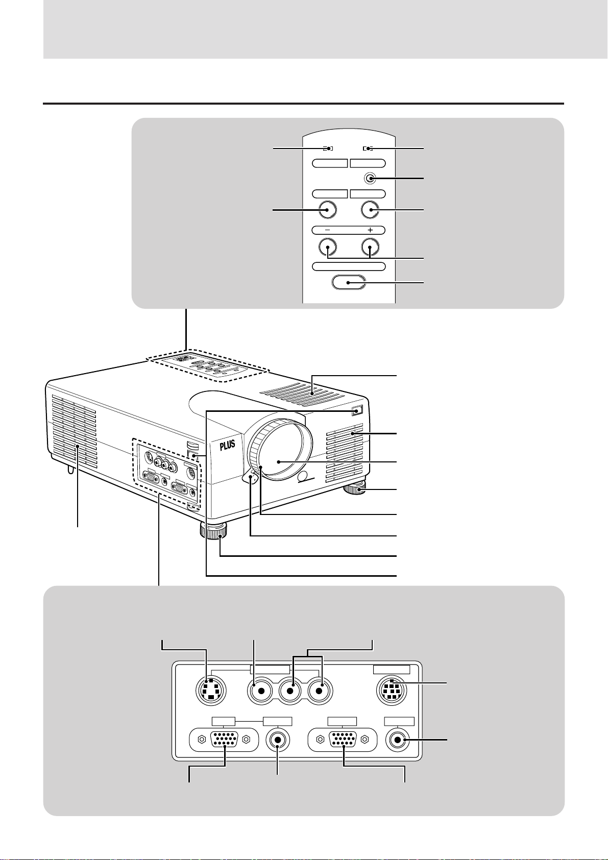
For operational instructions, refer to the page indicated in brackets.
Front and side panel view
Control panel
STATUS indicator [31]
SELECT button [21]
POWER indicator [16, 17]
STATUS POWER
POWER button [16, 17]
SELECT MENU
MENU button [21]
ADJUST
Cooling fan
S-VIDEO
RGB IN
VIDEO
VIDEO IN
L/MONO•AUDIO-R
AUDIO IN
RGB OUT
PC CONTROL
AUDIO OUT
DLP
ENTER
ADJUST +/– button [21]
ENTER button [17, 21]
Monaural speaker (1.0 W)
Ventilation
Lens and Lens cap [16, 17]
Adjuster (right) [17]
Focus ring [17]
Zoom ring lever [17]
Terminal Panel
VIDEO-IN
S-VIDEO jack [11]
RGB IN connector
[11, 12, 15]
VIDEO-IN
VIDEO jack [11]
VIDEO IN
VIDEOS-VIDEO L/MONO·AUDIO·R
RGB IN
AUDIO IN jack [11, 15]
E – 6
Adjuster (left) [17]
Remote sensor [5]
VIDEO-IN
L/MONO•AUDIO•R jacks [11]
PC CONTROL
RGB OUTRGB IN AUDIO IN
AUDIO OUT
RGB OUT connector
[15]
PC CONTROL port
(Connecting your PC to
this port enables you to
use the PC and serial
communication protocol to control the Data
Projector.)
AUDIO OUT jack
[15]
Page 7
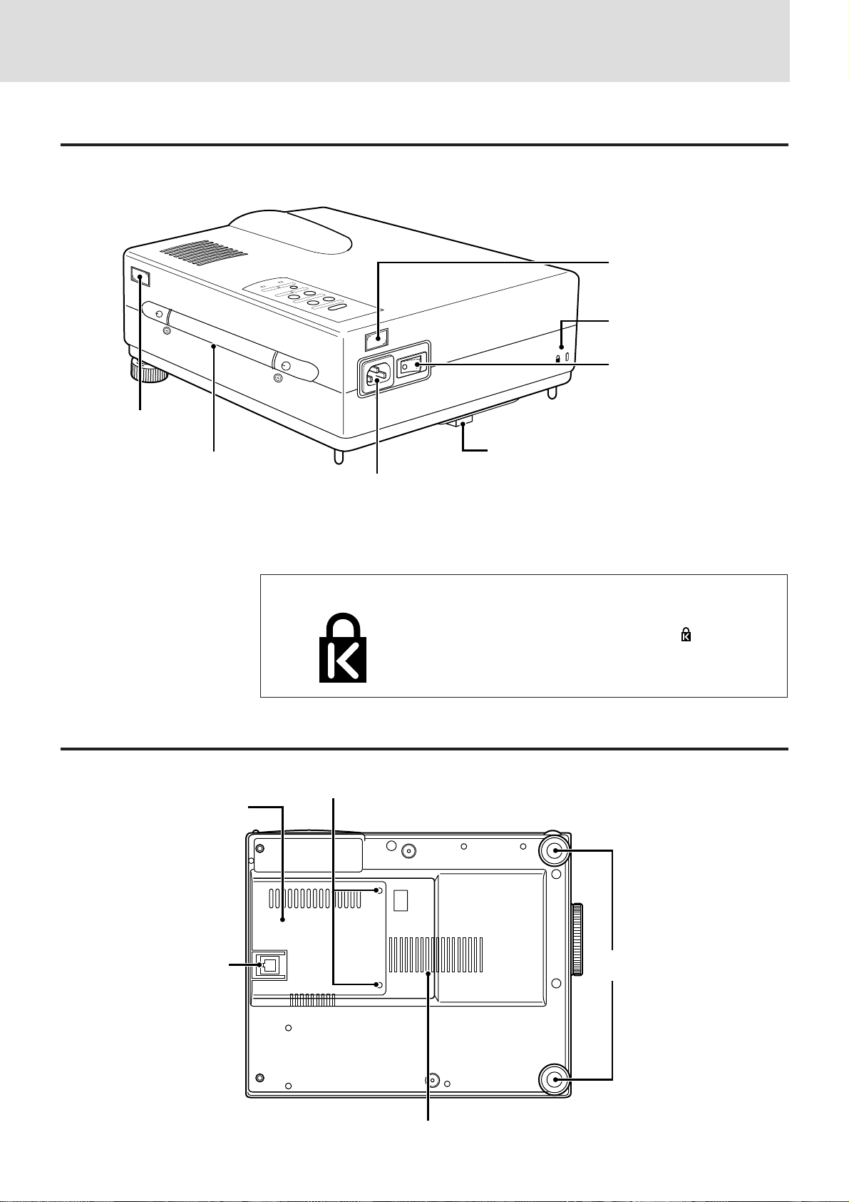
Rear and side panel view
Remote sensor [5]
AC IN
Remote sensor [5]
Built-in security slot
[see below]
POWER switch [16, 17]
POWER
Bottom
Handle
Lamp cover [32]
AC IN terminal [16]
Built-in Security Slot
Lamp cover securing screw [32]
Rear adjuster [17]
This security slot supports the MicroSaver® Security
System. MicroSaver® is a registered trademark of
Kensington Microware Inc. The logo is trademarked and owned by Kensington Microware Inc.
Rear adjuster [17]
Front adjusters [17]
Ventilation
E – 7
Page 8
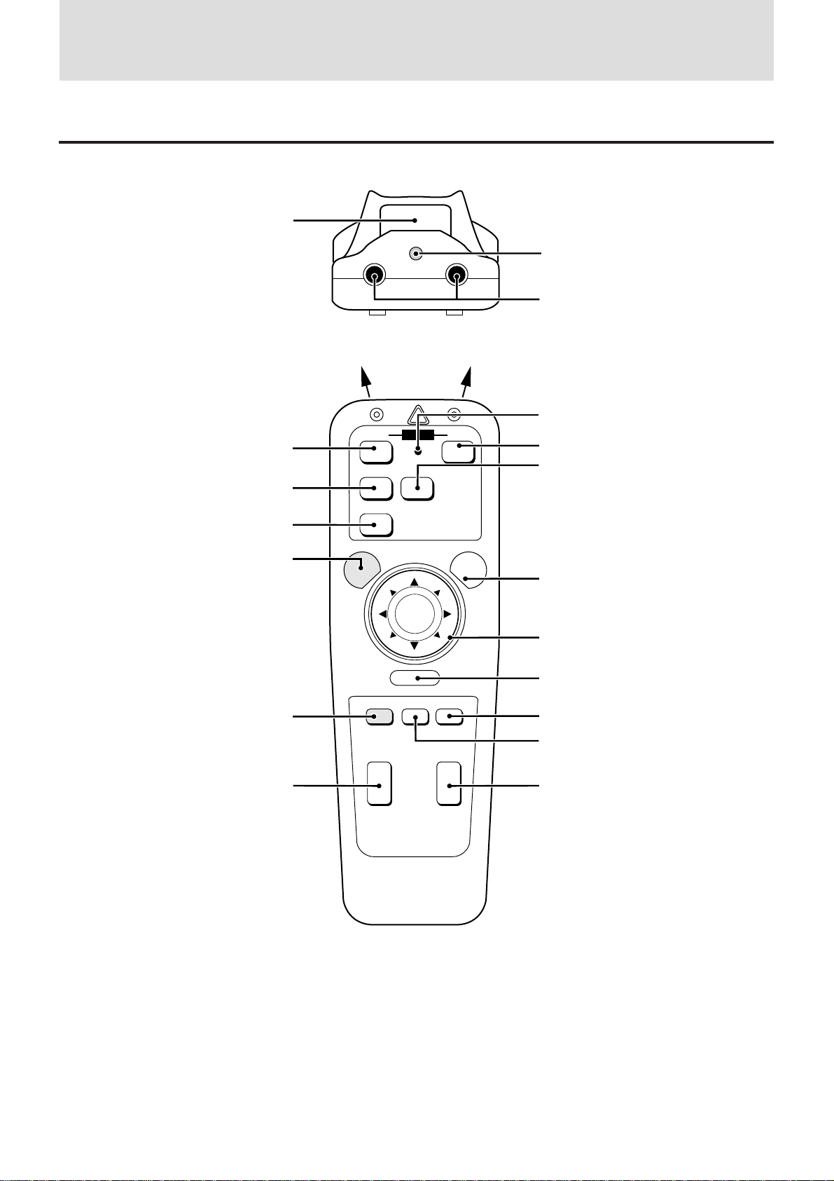
Parts and controls (continued)
Remote control
L-CLICK button [14, 21]
Laser pointer [19]
Infrared transmitter [5]
LED
Lights when any button is pressed.
OFF ON
POWER OFF button [17, 29]
VIDEO button [16]
RGB button [16]
MENU button [21]
VIDEO
MENU
POWER
S-VIDEO
RGB
LASER
POWER ON button [16, 29]
S-VIDEO button [16]
LASER button [19]
POSITION button [20]
MAGNIFY +/– button [17, 20, 29]
–
R-CLICK
POSITION MUTE FREEZE
MAGNIFY
+
–
PLUS
VOLUME
+
–
+
Cursor key [14, 20, 21]
R-CLICK button [14, 21]
FREEZE button [19]
MUTE button [19]
VOLUME +/– button [19]
E – 8
Page 9
Installation
The distance from the unit lens to the screen determines to the size of the projected image, therefore, you need to consider the place where you
set up the unit and screen before making connections. You also need to consider the screen size and height of the unit and screen as other
important factors.
Tip
A non-glossy wall may be used as a substitute for a screen.
WARNING
• Carrying The Data Projector
Always carry your Data projector in the carrying case. Ensure that the power cord and any other cables connecting to video sources are
disconnected before moving the projector. When moving the projector or when it is not in use, cover the lens with the lens cap.
• Only use your Data projector on a solid flat level surface. If the projector falls to the gr ound, you can be injured and the projector severely
damage.
• Do not use the Data projector where temperatures vary greatly. The projector must be used at temperatures between 5°C (41°F) and 35°C
(95°F).
• Do not expose the Data projector to moisture, dust, or smoke. This will harm the screen image.
• Ensure that you have adequate ventilation around your Data projector to allow hea t dissipation. Do not cover the vents on the bottom or the
side of the projector.
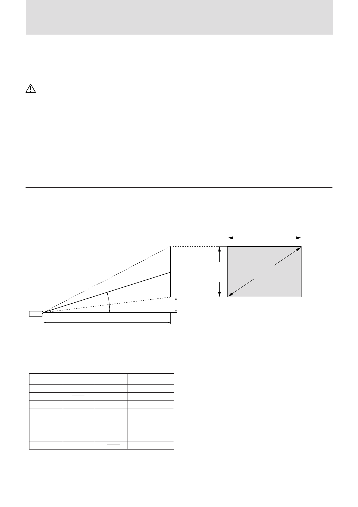
Positioning the unit
The projected image becomes larger as the distance between the unit and screen increases. The minimum image size is about 24 inches (0.61
m) diagonally at a distance of about 1.2 m (3 feet) and the maximum size is about 300 inches (7.6 m) at a distance of 12.0 m (39.37 feet) from
the screen. Use the following information when you fix the position of the unit.
Projecting distance and image size
Screen
11 to 15 degrees
(represented as “L” in the table and chart below)
• Horizontal projection position Lens centered left to right
• Vertical projection position
Screen size Projection distance (L) mDimension (H) mm
Inches Wide (W)
24 1.2 70
40 1.6 2.1 122
60 2.4 3.1 176
80 3.2 4.2 238
100 4.0 5.3 291
200 8.2 10.6 599
300 12.3 891
Projecting distance
Telephoto (T)
Both W & T
Screen
width
Screen
Height
Distance from center of lens to lower edge of screen
(represented as “H” in the table and chart below)
Screen size
(diagonal)
E – 9
Page 10
Installation (continued)
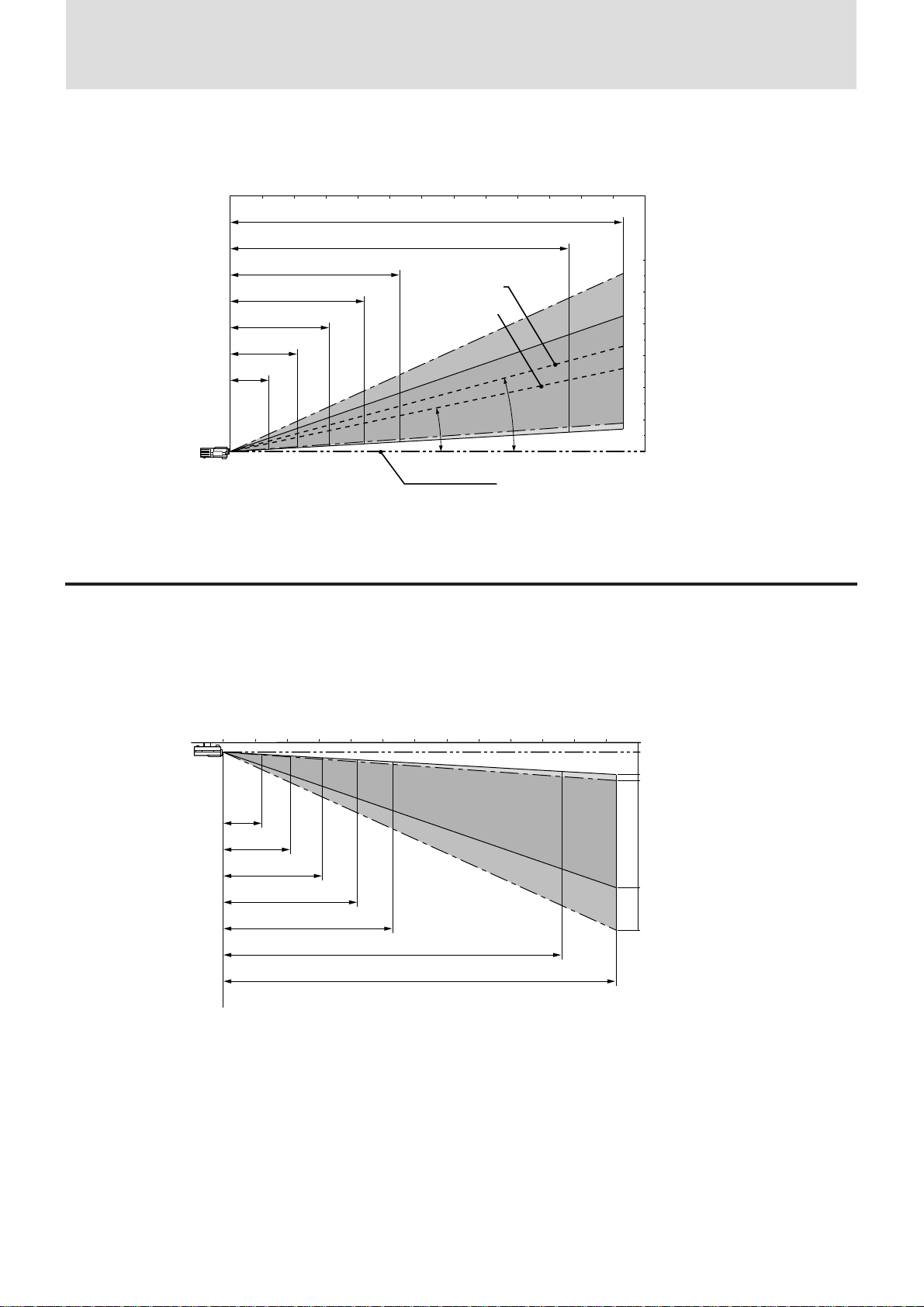
• Projecting distance and image size
Projection distance
Tele. Wide
233"~300"
Diagonal image size (inch)
200"
~
261"
100"~131"
80"~104"
60"~78"
40"~53"
24"~31"
4.2m
3.1m
2.1m
1.2m
5.3m
12.3m
10.6m
Image center in
wide mode
Image center
in telephoto
mode
15.3˚ ~ 14.6˚
11.9˚ ~ 11.3˚
Center of lens
)
12(m
11109876543210
)
6(m
5
4
3
2
1
0
Using the ceiling mounting fixtures
When using the ceiling hanging fixtures, select “FRONT/CEILING” in “PROJECTION” in “SETTING MENU” (see pages 17 and 24).
Note
Installing the Data Projector on the ceiling must be performed by qualified PLUS service personnel. Contact your PLUS dealer for more information.
Never attempt to install the Data Projector yourself.
Projection distance
)
12(m
Diagonal image size (inch)
Tele. Wide
24"~31"
40"~53"
60"
80"~104"
~
100"
200"
~
~
131"
261"
78"
1.2m
2.1m
3.1m
4.2m
233"~300"
11109876543210
5.3m
10.6m
12.3m
0mm (Ceiling)
184mm (Center of lens)
875mm
1,082mm
4,424mm
(In tele mode)
(In wide mode)
5,697mm
E – 10
Page 11
Connections
Connecting video equipment
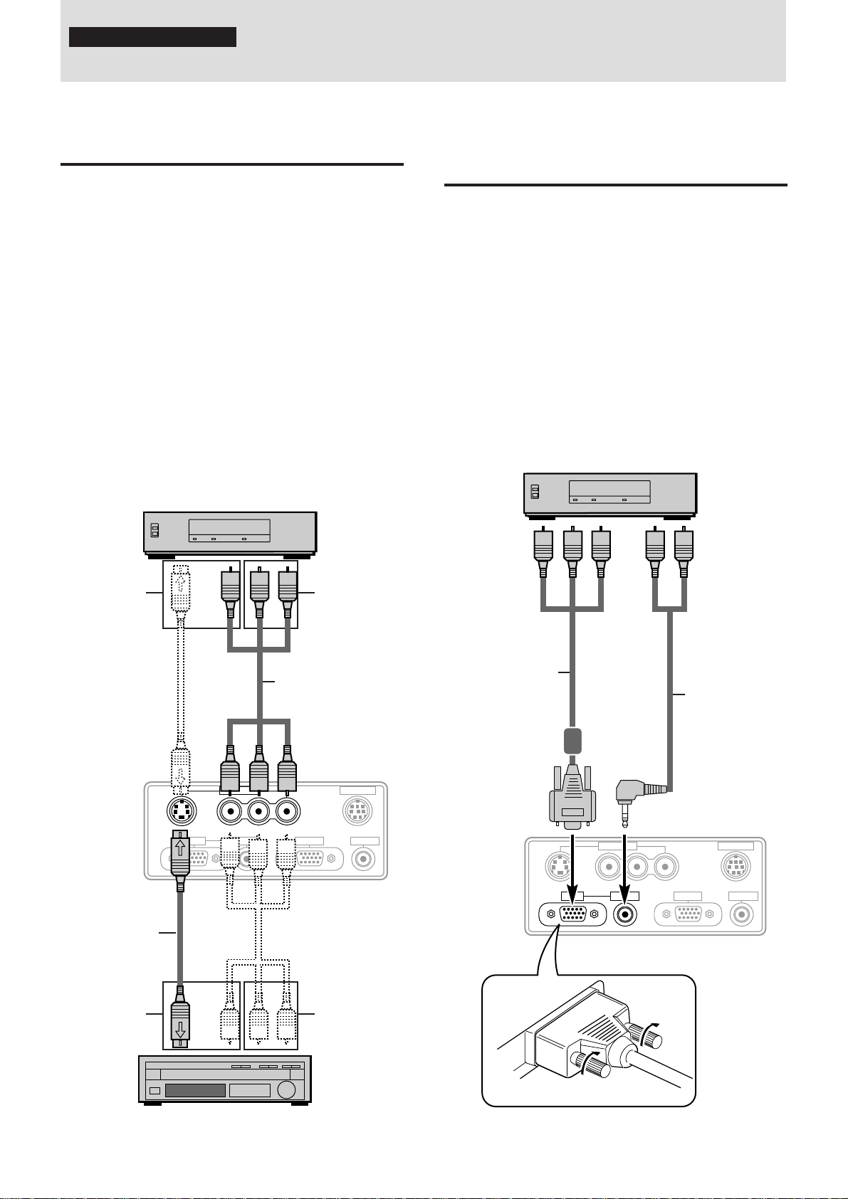
You can connect a document camera, VCR, laser disc player, and DVD player, etc.
Connecting to the VIDEO IN VIDEO/SVIDEO jacks
Y ou can connect up to tw o pieces of video equipment to the VIDEO
IN jacks following the illustration below. Two types of connections
can be made. Connect either using the cables indicated in dotted
lines or those in gray as shown in the drawing below.
• Y ou can switch the input source (picture) to VIDEO or S-VIDEO
even if you connect more than one piece of equipment. S-VIDEO
connection provides more vivid color and higher resolution
compared to VIDEO connection.
• You can output the sound of one component through the unit
speaker even when two components are connected.
Before connecting
• Turn off the components that are to be connected.
• The unit and computer will be turned on in “Using the Data
Projector” on page 16. Do not turn on either the computer or unit
until you read this section.
• Please also refer to the manual of the video component to be
connected.
VCR, document camera, etc.
To video
output jack
To audio
output Left/
Right jacks
Connecting video equipment that has
the component video signal (YCbCr)
output jacks to the RGB IN connector
You can also connect the video component to the RGB IN connector, if the video component has the component video (YCbCr)
signal jacks. This connection provides better picture quality than
the connections on the left column.
• You can switch the input source to VIDEO, S-VIDEO, or RGB.
• The AUDIO IN jack is for equipment connected to the RGB IN
connector.
Before connecting
• Turn off the components that are to be connected.
• The unit and computer will be turned on in “Using the Data
Projector” on page 16. Do not turn on either the computer or unit
until you read this section.
• Please also refer to the manual of the video component to be
connected.
DVD player, laser disc player,
document camera, etc.
T o YCbCr
signal output
jacks
To audio
output jacks
The unit
terminal panel
S-video cable
(supplied)
To video
output jack
Audio video cable
(supplied)
VIDEO IN
VIDEOS-VIDEO L/MONO·AUDIO·R
RGB OUTRGB IN AUDIO IN
To audio
output Left/
Right jacks
PC CONTROL
AUDIO OUT
YCbCr signal jacks/
RGB connector
adapter cable
(optional)
The unit
terminal panel
VIDEO IN
VIDEOS-VIDEO L/MONO·AUDIO·R
Mini-plug/pin-plug
adapter cable (not
supplied)
PC CONTROL
RGB OUTRGB IN AUDIO IN
AUDIO OUT
Laser disc player, DVD player,
document camera, etc.
Plug the cable terminal into the RGB
connector securely then tighten the screws.
E – 11
Page 12
Connecting a PC or Macintosh
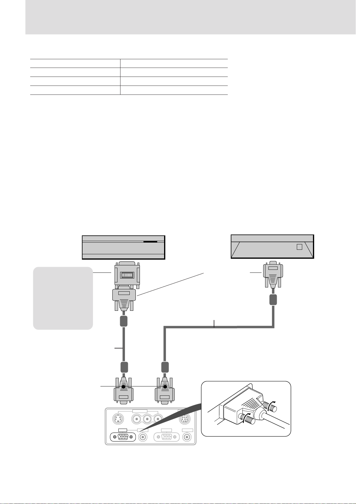
Connecting a PC or Macintosh to the Data Projector will enable you to project your computer screen images for impressive presentations.
• The following display standards are supported:
VGA 640×480 for graphics VGA 640×400 for graphics
VGA 640×350 for graphics VGA 720×400 for text
VGA 720×350 for text SuperVGA 800×600
Macintosh at 640×480 Macintosh at 832×624
• A PC, Macintosh, or computer equipped with a XGA adapter or compatible graphics adapter can easily be connected.
• If your PC does not support XGA you will need to install a XGA graphics board. Consult your computer's owner's manual for your XGA
configuration. If you need to install a new board, refer to the manual supplied with your new graphics board for installation instructions.
Notes
• Refer to the owner's manual supplied with your computer for more information about the video output requirements of the computer and any special
identification or configuring required by the projector image and monitor.
• Some Macintosh PowerBooks may need to set the mirroring to off to output 800×600 dot signals. Please consult your PowerBook manual or
computer dealer for details.
Before connecting
• Turn off the computer that is to be connected.
• The unit and computer will be turned on in “Using the Data Projector” on page 16. Do not turn on either the computer or unit until you read
this section.
• Please also refer to the manual of the computer to be connected.
Monitor adapter for
Macintosh
You may need to
change the DIP
switch setting
depending on the
machine to be
connected. See next
page.
PC/Macintosh
multicable
(supplied)
Mini D-Sub 15-pin
connector
Macintosh desktop computer
IBM PC/AT compatible machine or
Macintosh with Mini D-sub 15-pin
connector
Mini D-Sub 15-pin
connector
PC/Macintosh
multicable
(supplied)
The unit
terminal panel
VIDEO IN
VIDEOS-VIDEO L/MONO·AUDIO·R
RGB OUTRGB IN AUDIO IN
PC CONTROL
AUDIO OUT
Plug the cable connector into the
RGB connector securely and tighten
the screws.
E – 12
Page 13
Note on the PowerBook connection
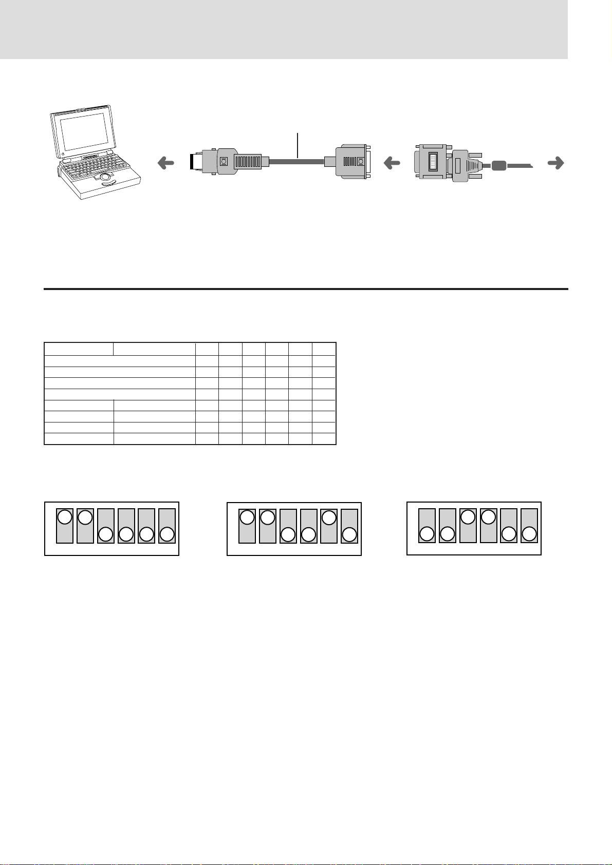
Depending on the model of your PowerBook, the additional Apple video cable adaptor may be required with the above connection.
Video cable adaptor
To the Data Projector
Modifying the DIP switch (for Macintosh) setting
Modify the DIP switch setting checking the DIP switch setting table below.
DIP switch setting (● = ON)
MONITOR RESOLUTION 1 2 3 4 5 6
MULTIPLE SCAN 21 ●● ●
MULTIPLE SCAN 17 ●● ●
MULTIPLE SCAN 16 ●● ●●
VGA/SVGA ●●
21 COLOR 1152×870 ●●●●
19 COLOR 1024×768 ●●
16 COLOR 832×624 ●●
13 COLOR 640×480 ●●
Inch 13
ON
123456
MULTIPLE SCAN 17 VGA/SVGA
ON
123456
ON
123456
E – 13
Page 14
Using the remote control as a computer
IBM/Mac EXT.IR
mouse – Wireless mouse function
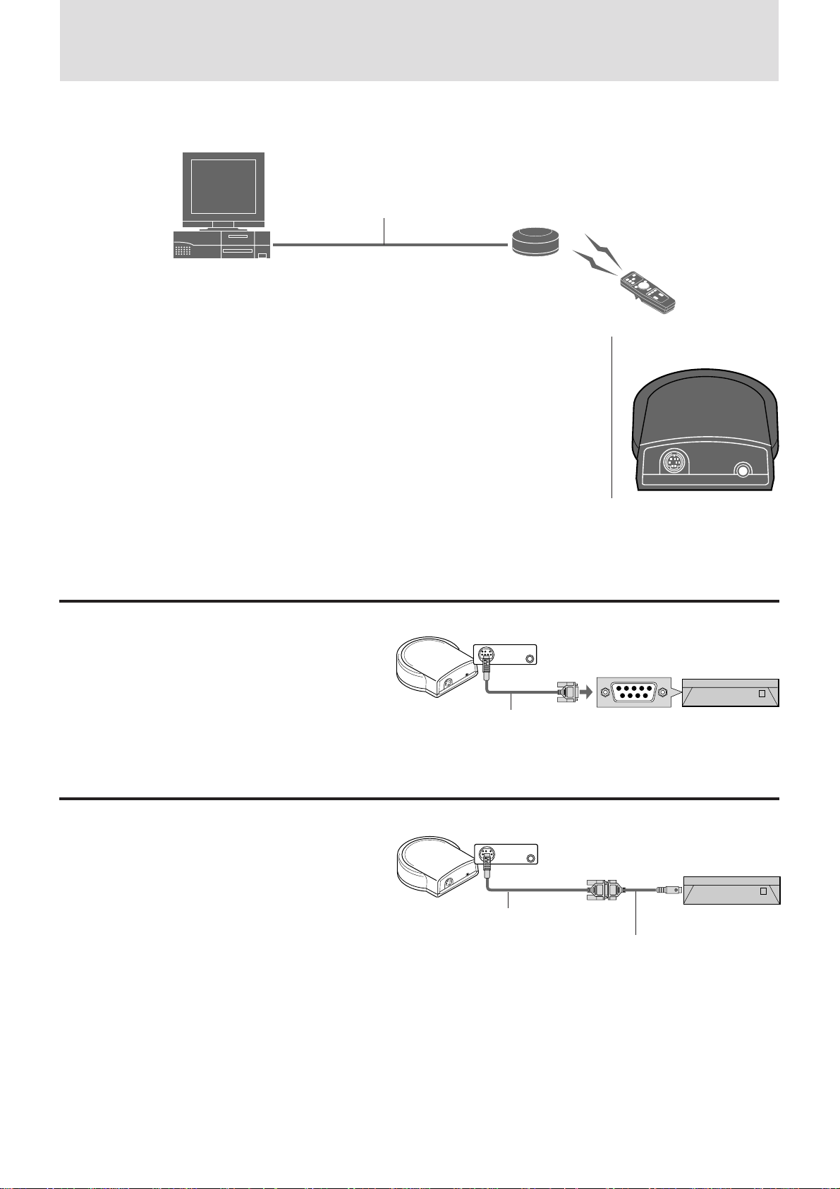
The supplied remote mouse receiver enables you to operate your computer's mouse functions from the remote control. It is a
great way to control your computer-generated presentations.
Serial mouse
cable (supplied)
Connect to
the IBM/Mac
connector
(see below)
• The cursor key on the remote control operates the computer mouse functions.
• If a Windows computer is connected, the L-CLICK button on the remote control operates as the
computer mouse left click button and the R-CLICK button as the computer mouse right click button.
• If the Macintosh computer is connected, the L-CLICK and R-CLICK buttons operate in the same way
as the computer mouse click button.
• While the menu is displayed on the screen (see page 21), the cursor key, L-CLICK and R-CLICK
buttons will operate to control the menu.
Connectors of the remote
mouse receiver
Before connecting
• Turn off the computer, then remove the current mouse.
• Connect the computer and remote mouse receiver with the supplied serial mouse cable as shown in the above illustration.
• The unit and computer will be turned on as described in “Using the Data Projector” on page 16. Do not turn on either the computer or unit
until you read this section.
• Please also refer to the manual of the computer to be connected.
Connecting the remote mouse receiver to an IBM PC/AT computer
Connect the IBM/Mac connector on the remote mouse
receiver and PC’s mouse port with the supplied serial
cable.
Remote mouse receiver
To the IBM/Mac connector
Serial mouse cable
(supplied)
IBM PC/AT
Connecting the remote mouse receiver to an IBM PS/2 or Macintosh computer
Connect the supplied serial cable to the IBM/Mac connector on the remote mouse receiver.
Connect the supplied mouse adapter to the other end of
the serial cable and the computer mouse port. Note that
two types of mouse adapters are supplied; one is for
IBM PS/2 and the other is for Macintosh.
Remote mouse receiver
To the IBM/Mac connector
Serial mouse cable
(supplied)
Mouse adapter for IBM PS/2 (supplied) or
Mouse adapter for Macintosh (supplied)
E – 14
IBM PS/2 or
Macintosh
Page 15
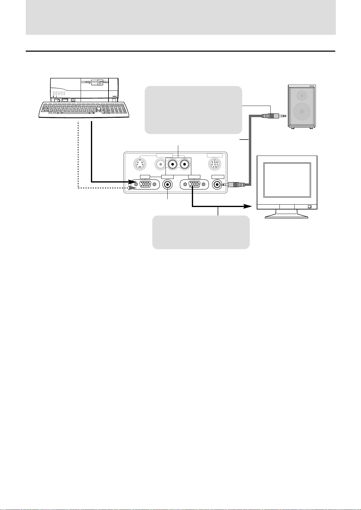
Additional connections
Outputting video/sound signals to another monitor/speaker via an amplifier
Computer or video equipment
Speaker with an amplifier
When VIDEO or S-VIDEO is selected
as the input source, the sound from
the VIDEO IN L/MONO•AUDIO•R
jacks (A) will be output.
When RGB is selected as the input
source, the sound from the AUDIO IN
(B) jack will be output.
The unit terminal panel
Note
Additional adapters may be required to connect to
another monitor depending on the type of the monitor .
A
VIDEO IN
VIDEOS-VIDEO L/MONO·AUDIO·R
PC audio calbe
PC CONTROL
RGB OUTRGB IN AUDIO IN
(supplied)
AUDIO OUT
B
The video signal from the RGB IN
connector will always be output
when the unit is projecting even if
VIDEO or S-VIDEO is selected as the
input source.
Monitor
E – 15
Page 16
Operation
STATUS
MENUSELECT
ADJUST
ENTER
POWER
Using the Data Projector
Before starting
• Remove the lens cap from the lens. Please retain it because it
must be replaced after use.
• Don’t use the Data Projector in a bright room and don’t expose
the screen to direct sunlight or other strong light sources.
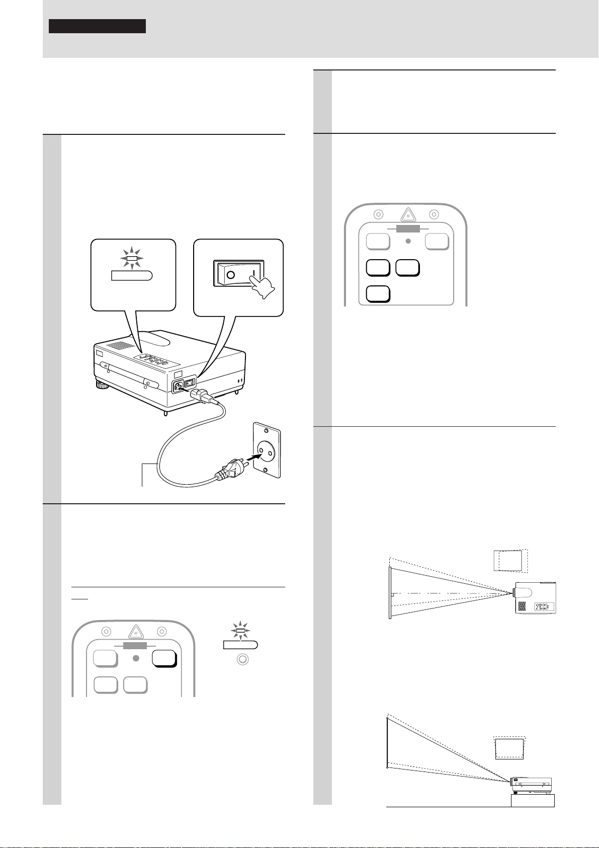
1 1 Connect the supplied power cable to
the unit, then to the wall outlet (the
mains).
2 Press the “I” side of the POWER switch
(main power) on the back of the unit.
The POWER indicator on top of the unit lights
in amber.
2
POWER
Lights in amber
(Standby)
AC IN POWER
Press “I” side
3 T urn on the connected sour ce (computer,
VCR, DVD player, etc.).
If you use a video component, start playback for
screen/image adjustment.
4 Press either VIDEO, S-VIDEO, or RGB to
select the input source.
You can also select the input source with the
menu operation (see page 21).
OFF ONPOWER
VIDEO
S-VIDEO
RGB
Notes
• If the blue, black, or focus pattern screen (the background
type differs depending on the “BACKGROUND” setting.
See page 24.) is projected, check the following:
– Is the source properly connected to the unit?
– Is the source component or computer turned on?
– Are the video signals coming to the unit?
• The video resolution of the connected computer can be
changed. See page 18.
1
Power cable (supplied)
2 Press the POWER ON button on the re-
mote control or the PO WER button on top
of the unit to turn on the unit.
The POWER indicator on top of the unit turns to
green and start blinking.
It will take one minute for the unit to be ready to
use. Wait until the indicator stops blinking and
lights steadily in green.
OFF ONPOWERPOWER
VIDEO S-VIDEO
Note
While the POWER indicator is blinking, the unit doesn’t turn
off even if you press the POWER OFF button on the remote
control or the POWER button on the unit.
Tip
If you set “ AUTO STAR T” to “ON” in the menu (see page 28),
the unit will turn on automatically after setting the POWER
switch to on in step 1.
POWER
Green light blinks
↓
Then lights steadily
in green
5 Adjust the position and height of the unit.
Move the unit to the position where the projected
image is horizontally centered to the screen.
• When the projected image is offset
horizontally
Adjust the position of the unit so that the unit is
square to the screen.
View from the top
• When the pr ojected image is offset ver -
tically
Adjust the height balance of the unit with the
adjusters.
View from the side
Screen
Screen
E – 16
Page 17
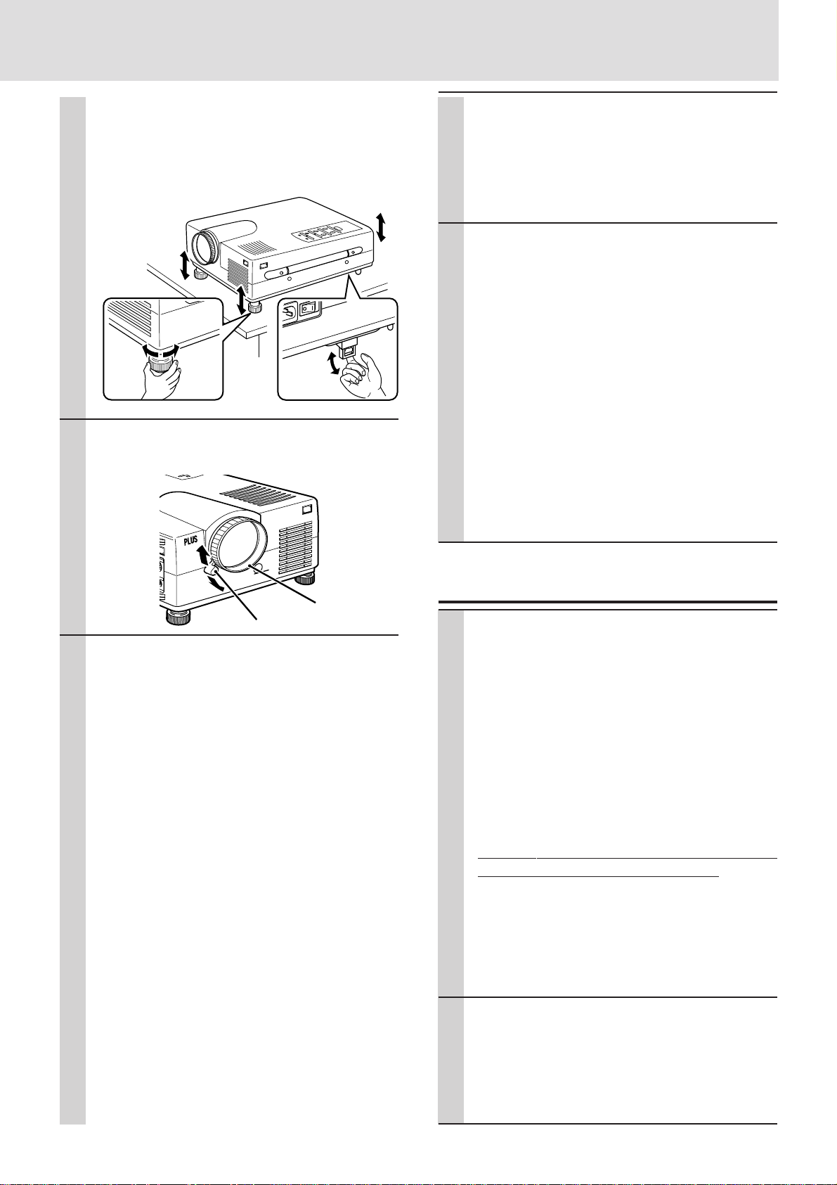
Using the adjusters to adjust the height balance
T
There are two front adjusters and a rear adjuster.
T o lo wer the position of the screen, pull out the folded leg of the
rear adjuster.
For the front adjusters, rotate each adjuster until the unit is
vertically parallel to the screen.
Up Down
Pull out
6 Adjust the image size with the zoom ring
lever , then adjust the f ocus with the focus
ring.
8 Adjust the picture elements and select
the picture type.
You can adjust the picture elements (see page
27), select the picture type according to the video
contents (see page 28) and wide screen (see
page 28).
9 Start using the Data Projector.
The following functions are available while using
the Data Projector:
• Adjusting the volume of the unit speaker
(see pages 19 and 24),
• Using the laser pointer (see page 19),
• T urning off the image and m uting the sound
temporarily (see page 19),
• Freezing a moving picture (see page 19), and
• Enlarging the picture (see page 20).
Note
If “POWER OFF” is set to “ON” (see page 28), the image will
be turned off if the unit has been left unoperated for five
minutes with an RGB input source.
If the image is suddenly turned off while projecting a computer
image, the computer’s screen sav er or the unit’s POWER OFF
function may be activated.
ROL
OUT
DLP
After using the Data Projector
Focus ring
Zoom ring lever
7 Change the unit setting to suit to the
projecting method and selected source
as described in step 4.
• Select the type of projection
If the projected image is horizontally reversed
or upside down, change the projection type.
See page 24.
• If the component video signal output
jacks of the video component are connected to the RGB IN connector (see
page 11), set “INPUT MODE” to “YCbCr”
in the menu.
This setting provides a better picture image.
See page 24.
• Adjust the projected image from the
source connected to the RGB IN connector.
The resolutions most suitable to the incoming
signals will automatically be selected. However , if an y vertical banding, noise, dot interference, or crosstalk appears on the screen, adjust “PICTURE ADJ,” then “FINE PICTURE”
using the menus. You can also adjust the horizontal and vertical position of the image. See
pages 25 to 27.
1 • Operating with the remote control
Press the POWER OFF button a little bit
longer.
• Operating with the unit
1 Press the POWER button.
“POWER OFF/ENTER” appears on the
screen.
2 Press ENTER.
When you have turned off the unit, the POWER
indicator will star t blinking then turn to amber in
one minute.
Never turn off the POWER switch (main power)
while the POWER indicator is blinking.
To cancel turning off the unit when “POWER OFF/
ENTER” is appearing on the screen
See “Canceling turning off the unit when ‘POWER OFF/
ENTER’ is appearing on the screen” on page 29.
Please also read
“Activating the on-screen function” on page 29.
2 If the POWER indicator is lit in amber,
press the “O” side of the POWER switch
(main power) on the back of the unit.
The POWER indicator goes out.
Disconnect the power cord if it is not to be used
for an extended period.
E – 17
Page 18

Using the Data Projector (continued)
Changing computer’s video resolutions
Depending on your computer's graphic capability, you may be able
to select one of several resolutions. Generally a computer- either a
PC or Macintosh- with 1 MB VRAM will run:
640 × 480 at 16.7 million colors (24 bit Truecolor)
800 × 600 at 65,000 colors.
1024 × 768 at 256 colors.
As the resolution increases, the number of colors you can run
decreases. With 2 MB VRAM a computer will run:
640 × 480 at 16.7 million colors (24 bit Truecolor).
800 × 600 at 16.7 million colors (24 bit Truecolor).
1024 × 768 at 65,000 colors.
1280 × 1024 at 256 colors.
Windows 95
There are two methods you can use to change your resolution.
Method 1
1 Move your cursor to the background image and click.
2 In the "Properties" menu, select "Settings."
3 Change your resolution and click "OK."
4 You may be asked to reboot for the changes to take ef fect,
or a message saying that "Windows is about to r esize your
display" may appear. You' ll be asked if you want to keep
your settings. Select "Yes."
Notebook computers and resolution
standards
This Data Projector is designed to project industry standardized
video such as VESA (Video Electronics Standards Association) or
VGA (Video Graphics Array). Notebook computers do not use
industry standards. They use whatev er timing is necessary to match
their local LCD display. The end result is typicall y not standard. By
turning off your notebook's display, the timing parameters are a bit
more like the real VESA or VGA signal.
Method 2
1 Click on your "My Computer" icon.
2 Open "Control Panel" and select "Display."
3 Change your resolution and click "OK." after the new
resolution is selected.
4 You may be asked to reboot for the changes to take ef fect,
or a message saying that "Windows is about to r esize your
display" may appear. You' ll be asked if you want to keep
your settings. Select "Yes."
Windows 3.1
1 Click on the "Main" icon and open "Control Panel."
2 Select "Change System Settings" and click on "Option."
3 Choose "Change Display Settings."
4 Select the resolution you want.
5 Choose the current or desired drive.
6 Restart Windows for the changes to take effect.
Macintosh
1 Under the Apple menu, select "Control Panels" and open
"Monitors."
2 Click and open "Options."
3 Select your new resolution and click "OK."
E – 18
Page 19
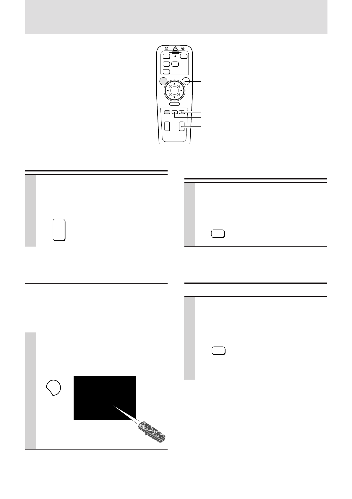
Various functions while using the Data
Projector
OFF ONPOWER
VIDEO
S-VIDEO
RGB
MENU
–
POSITION MUTE FREEZE
MAGNIFY
R-CLICK
+
–
PLUS
VOLUME
LASER
LASER button
+
FREEZE button
+
–
MUTE button
VOLUME +/– button
Adjusting the volume of the unit speaker
Press VOLUME + to increase the volume
or – to decrease.
The volume can also be adjusted with the menu
operation (see page 24).
VOLUME
+
–
Using the laser pointer
You can highlight the desired point on the screen with the beamed
red light.
Caution
Do not look into the laser pointer while it is on, nor point the laser beam
at any other persons. This could result in serious eye damage or
blindness.
Turning off the image and muting the
sound temporarily
Press MUTE.
The image will turn off and the sound will be
muted at the same time. To restore the picture
and sound, press the button again.
MUTE
Freezing a moving picture
You can capture the desired frame of the moving picture.
Press FREEZE.
A still image of the current frame will be displayed. To restore the present picture, press the
button again.
Press LASER.
The red light will be beamed while pressing the
button. The light goes out when you release the
button.
LASER
FREEZE
Tip
The still picture can also be enlarged (see next page).
E – 19
Page 20
Various functions while using the Data
Projector (continued)
OFF ONPOWER
VIDEO
S-VIDEO
RGB
POSITION button
MAGNIFY button
MENU
–
POSITION MUTE FREEZE
MAGNIFY
+
–
PLUS
R-CLICK
VOLUME
LASER
+
Cursor key
+
–
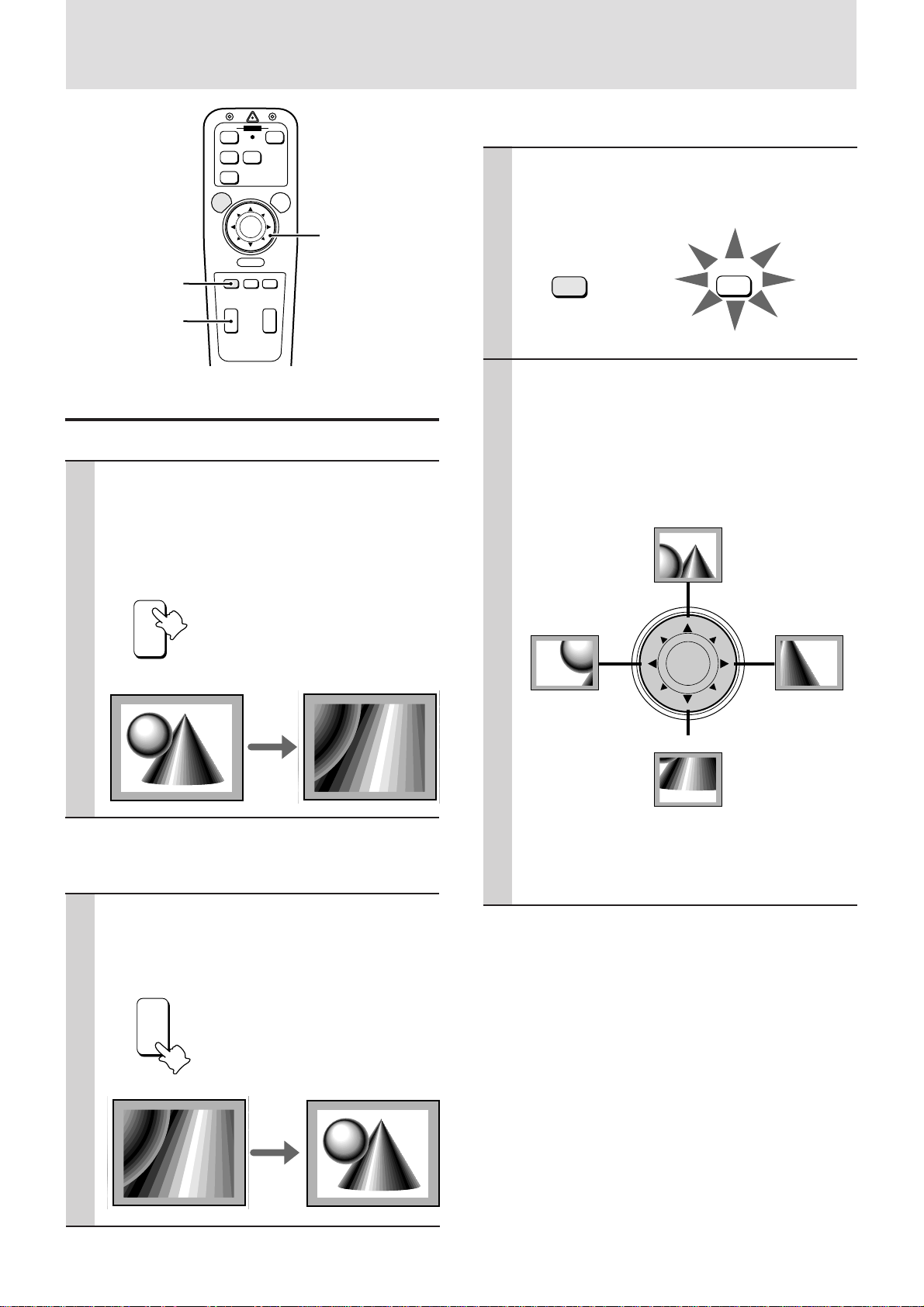
Enlarging the picture
You can enlarge the picture up to four times the normal size.
Press MAGNIFY +.
While the button is pressed the picture is enlarged until it becomes four times the normal
size.
Release the button at the desired size.
To move to the desired portion of the enlarged
picture
1 Press POSITION.
The button lights in red. If you don’t proceed to
step 2 within ten seconds, the button goes off.
POSITION
POSITION
2 Press the desired portion of the cursor
key while POSITION lights.
The moving directions are indicated by the eights
triangle marks on the cursor key. The picture will
move in the direction pointed by the mark where
you are pressing.
Move upward
MAGNIFY
+
–
Four times as large
Normal size
as the normal size
To reduce the size of the enlarged picture
Press MAGNIFY –.
While the button is pressed the picture is reduced
until it becomes the normal size.
MAGNIFY
+
Move leftward
–
Move rightward
+
Move downward
Note
The normal size of the picture cannot be moved because the
whole image is fully displayed.
–
Enlarged size
Normal size
E – 20
Page 21
Menu operation
+–+
–
R-CLICK
STATUS
MENUSELECT
ADJUST
ENTER
POWER
Basic operation (Selecting the input source)
OFF ONPOWER
VIDEO
S-VIDEO
MENU button
RGB
MENU
–
R-CLICK
POSITION MUTE FREEZE
MAGNIFY
+
–
PLUS
VOLUME
LASER
+
–
+
L-CLICK button
(At the back of
the remote
control)
Cursor key
R-CLICK button
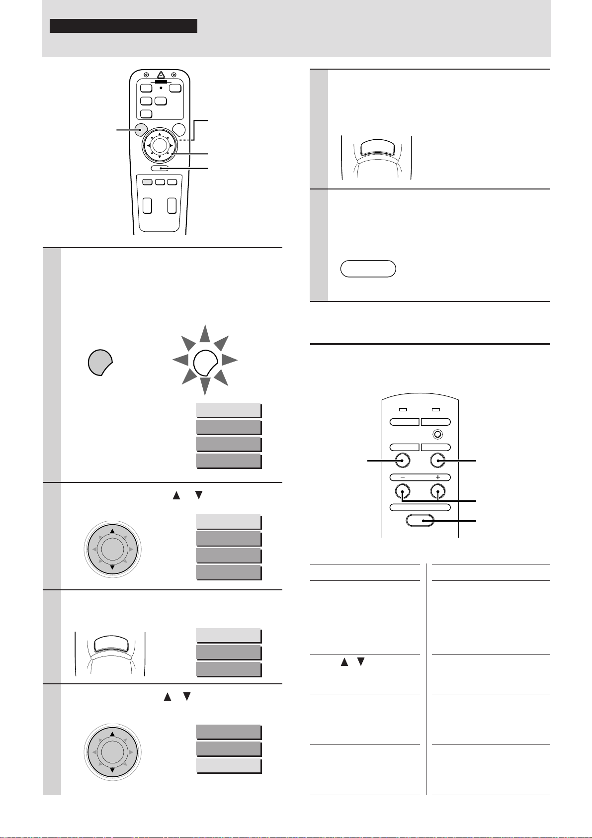
1 Press MENU.
The button lights in red and the main menu
appears on the screen.
If you don’t proceed to step 2 within ten seconds,
the button goes off.
MENU
Note
The menu will not be displayed if the picture is enlarged even slightly. In
such a case, reduce the picture size to normal before
starting the menu operation.
MENU
SOURCE MENU
IMAGE ADJ MENU
POWER MENU
SETTING MENU
5 Press L-CLICK.
The source you’ve selected in step 4 will be
confirmed, then the picture from the selected
source will be projected on the screen.
6 Press R-CLICK to turn off the menu dis-
play.
Whenever you wish to turn off the menu display,
press R-CLICK button.
Operating with the unit
The menu operation is explained using the remote control, however, it can also be controlled with the unit operation buttons.
To operate with the unit, refer to the comparison table below.
SELECT
button
MENU
button
2 Press the cursor / key to select
“SOURCE MENU.”
SOURCE MENU
IMAGE ADJ MENU
POWER MENU
SETTING MENU
3 Press L-CLICK.
The source menu appears on the screen.
VIDEO
S-VIDEO
RGB
STANDARD
4 Press the cursor / key to select the
desired input source.
VIDEO
S-VIDEO
RGB
STANDARD
ADJUST +/–
buttons
ENTER button
The remote control and unit button comparison table
Remote control buttons
MENU
The main menu appears on
the screen when you press
this button.
To turn off any menu, press
R-CLICK.
Cursor / key
Press either key to select the
menu item.
L-CLICK
Press this button whenever
confirming operation is required.
Cursor + / – key
Press either key to choose
the setting or value of the
selected menu item.
Unit operation buttons
MENU
The main menu appears on the
screen when you press this
button.
To turn off an y menu, press R-
CLICK on the remote control.
SELECT
Each press change the menu
item to the next.
ENTER
Press this button whenever
confirming operation is required.
ADJUST + / –
Press either button to choose
the setting or value of the selected menu item.
E – 21
Page 22
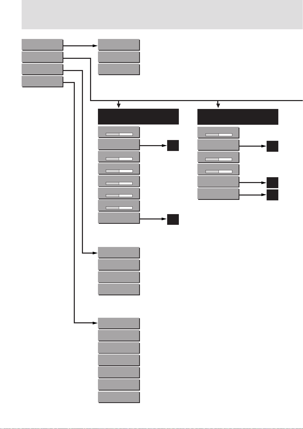
Menu structure
SOURCE MENU (21)
IMAGE ADJ MENU (24)
POWER MENU (28)
SETTING MENU (24)
VIDEO (21)
S-VIDEO (21)
RGB (21, 26)
STANDARD
When the input source is
VIDEO or S-VIDEO
VOLUME (24)
–+
IMAGE MODE (28)
BRIGHTNESS (27)
–+
CONTRAST (27)
–+
COLOR (27)
–+
TINT (27)
–+
SHARPNESS (27)
–+
WHITE BALANCE (27)
A
B
When the input source is RGB
and “INPUT MODE” is “RGB”
VOLUME (24)
–+
IMAGE MODE (24)
A
BRIGHTNESS (27)
–+
CONTRAST (27)
–+
WHITE BALANCE (27)
B
ALIGNMENT (26)
C
LAMP USAGE (29)
0HOURS
AUTO START (28)
OFF
POWER OFF (28)
OFF
DISPLAY (29)
ON
CUSTOM MEMORY (26)
CUSTOM 1
BACKGROUND (24)
BLUEBACK
PROJECTION (24)
FRONT / FLOOR
LANGUAGE (24)
ENGLISH
RESET (27)
48KHz / 60Hz
ALL RESET (27, 29)
COMPLETED
STARTING RGB (27)
STANDARD
E – 22
Page 23
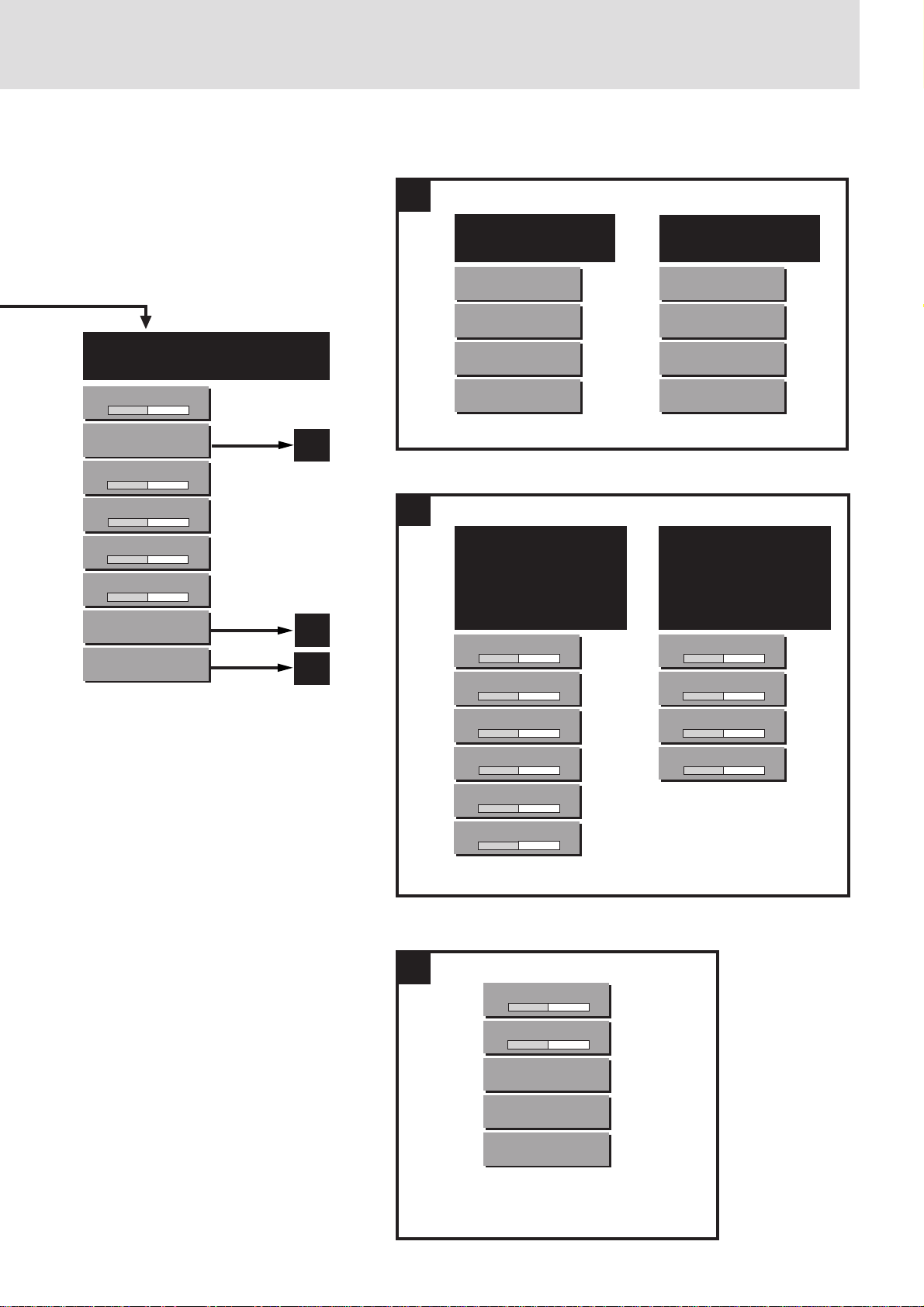
A
When the input source is RGB
and “INPUT MODE” is “YCbCr”
VOLUME (24)
–+
IMAGE MODE (24)
BRIGHTNESS (27)
–+
CONTRAST (27)
–+
COLOR (27)
–+
TINT (27)
–+
WHITE BALANCE (27)
ALIGNMENT (26)
A
B
C
B
When the input source
is VIDEO or S-VIDEO
GAMMA (28)
NORMAL
INPUT MODE (28)
GRAPHICS
DISPLAY MODE (28)
NORMAL
WHITE PICTURE (28)
NORMAL
• When the input source
is VIDEO or S-VIDEO
• When the input source
is RGB and “INPUT
MODE” is “RGB”
BRIGHTNESS R (27)
–+
BRIGHTNESS G (27)
–+
BRIGHTNESS B (27)
–+
CONTRAST R (27)
–+
CONTRAST G (27)
–+
CONTRAST B (27)
–+
When the input source
is RGB
GAMMA (28)
NORMAL
INPUT MODE (24)
RGB
DISPLAY MODE (28)
NORMAL
WHITE PICTURE (28)
NORMAL
When the input source
is RGB and “INPUT
MODE” is “YCbCr”
COLOR Cr (27)
–+
COLOR Cb (27)
–+
HUE Cr (27)
–+
HUE Cb (27)
–+
C
E – 23
H POSITION (26)
–+
V POSITION (26)
–+
AUTO PICTURE (26)
OFF
*
PICTURE ADJ (26)
1160
FINE PICTURE (26)
*
64
* Displayed only when “AUTO
PICTURE” is “OFF.”
Page 24
Selecting the
Selecting the
projection type
This reorients your image for your type of projection.
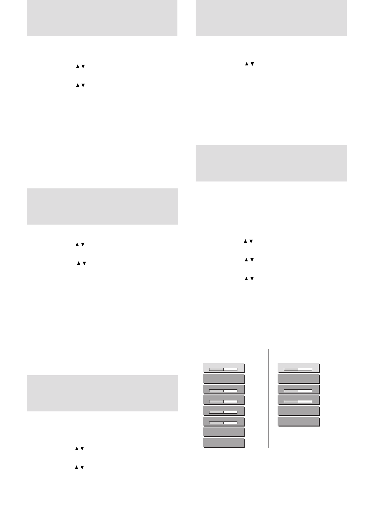
1 Press MENU to display the main menu.
2 Press the cursor / key to select “SETTING MENU.”
3 Press L-CLICK to display the SETTING MENU.
4 Press the cursor / key to select “PROJECTION.”
5 Pr ess the cursor + / – key to select the projection type
which suits the Data Projector setup conditions.
The following four projection types can be selected:
• FRONT FLOOR (Normal),
• REAR CEILING (Upside do wn and horizontally reversed),
• REAR FLOOR (Horizontally reversed), or
• FRONT CEILING (Upside down).
6 Press L-CLICK.
Selecting a
display language
1 Press MENU to display the main menu.
2 Press the cursor / key to select “SETTING MENU.”
3 Press L-CLICK to display the SETTING MENU.
4 Press the cursor / key to select “LANGUAGE,” then
press the cursor + / – to select one of the following
languages:
• ENGLISH (English),
• DEUTSCH (German),
• FRANÇAIS (French),
• ITALIANO (Italiano),
• ESPAÑOL (Spanish),
• SVENSKA (Swedish), or
• œ{Œ (Japanese).
5 Press L-CLICK.
Adjusting the
volume
The volume can also be adjusted with VOLUME +/– on the remote
control (see page 19).
1 Press MENU to display the main menu.
2 Press the cursor / key to select “IMA GE ADJ MENU .”
3 Press L-CLICK to display the IMAGE ADJ MENU.
4 Press the cursor / key to select “VOLUME,” then press
the cursor + / – key to adjust the volume.
background
1 Carry out steps 1 to 3 in “Selecting the projection type”
on the left column.
2 Press the cursor / key to select “BACKGROUND.”
3 Press the cursor + / – key to select one of the following
background types:
• BLUEBACK,
• BLACKBACK, or
• FOCUS PATTERN.
4 Press L-CLICK.
Setting “INPUT
MODE” to “YCbCr”
When you have connected the component video (YCbCr) signal
output jacks of the video component to the RGB IN connector on
the unit (see page 11), set “IMAGE MODE” to “YCbCr” to obtain
better picture quality.
1 Select the input source RGB (see page 16 or 21).
2 Press MENU to display the main menu.
3 Press the cursor / key to select “IMAGE ADJ MENU .”
4 Press L-CLICK to display the IMAGE ADJ MENU.
5 Press the cursor / key to select “IMAGE MODE.”
6 Press L-CLICK to display the IMAGE MODE menu.
7 Press the cursor / key to select “INPUT MODE.”
8 Press the cursor + / – key to select “YCbCr.”
Each press changes the setting to “RGB” or “YCbCr.”
9 Press L-CLICK.
The change of settings will be confirmed.
When you display the IMAGE MODE menu next, the
following IMAGE MODE menu for YCbCr will be dis-
played.
IMAGE ADJ MENU for
YCbCr (video component)
VOLUME
–+
IMAGE MODE
BRIGHTNESS
–+
CONTRAST
–+
COLOR
–+
TINT
–+
WHITE BALANCE
ALIGNMENT
When you have disconnected the present video
component from the RGB IN connector and
reconnected a computer
Set “INPUT MODE” to “RGB” in step 8 above.
IMAGE ADJ MENU for RGB
(computer)
VOLUME
–+
IMAGE MODE
BRIGHTNESS
–+
CONTRAST
–+
WHITE BALANCE
ALIGNMENT
E – 24
Page 25

Adjusting the image from the source
connected to the RGB IN connector
The Data Projector selects the most suitable resolutions as shown in the “Timing Chart” belo w according to the incoming signals from the RGB
IN connector (When “RGB” is set to “STANDARD.” See page 26). However, you may need manual adjustment depending on the computer
or video component connected to the RGB IN connector (see pages 11 and 12). If you have any of vertical banding, noise, dot interference,
or crosstalk on the projected picture, adjust clock frequency with “PICTURE ADJ” then c loc k phase with “FINE PICTURE” (see next pa ge).
You can also adjust the horizontal and vertical position of the image (see page 26).
Timing Chart
Signal Resolution H. Sync. V. Sync. Dot Clock
(kHz) (Hz) (MHz)
1 NTSC 640 × 480 15.734 59.94 2 PAL 768 × 576 15.625 50 3 SECAM 768 × 576 15.625 50 4 VESA 640 × 350 37.86 85.08 31.5
5 Mac 640 × 400 35 66 30.24
6 IBM 640 × 400 31.47 70 25.175
7 VESA 640 × 400 37.86 85.08 31.5
8 VESA 640 × 480 31.47 59.94 25.175
9 IBM 640 × 480 31.47 60 25.175
10 Mac 640 × 480 31.47 60 25.175
11 Mac 640 × 480 34.97 66.67 31.334
12 Mac 640 × 480 35 66.67 30.24
13 VESA 640 × 480 37.86 72.81 31.5
14 VESA 640 × 480 37.5 75 31.5
15 IBM 640 × 480 39.375 75 31.49
16 VESA 640 × 480 43.269 85.01 36
Signal Resolution V. Sync. H. Sync. Dot Clock
(Hz) (kHz) (MHz)
17 IBM 720 × 350 39.44 87.85 35.5
18 IBM 720 × 350 31.469 70.09 28.322
19 IBM 720 × 400 31.469 70.09 28.322
20 VESA 720 × 400 37.927 85.04 35.5
21 IBM 720 × 400 39.375 87.7 35.5
22 VESA 800 × 600 35.16 56.25 36
23 VESA 800 × 600 37.879 60.32 40
24 VESA 800 × 600 48.077 72.19 50
25 VESA 800 × 600 46.88 75 49.5
26 VESA 800 × 600 53.674 85.06 56.25
27 Mac 832 × 624 49.725 74.55 57.283 *
28 VESA 1024 × 768 48.363 60 65 *
29 VESA 1024 × 768 57.476 70.07 75
30 IBM 1024 × 768 58.131 72.03 79
31 Mac 1024 × 768 60.241 74.93 80 *
32 VESA 1024 × 768 60.023 75.03 78.75 *
*AccuBlend
The resolution of the Data Projector is 800 × 600. Other resolution images (e.g. 1024 × 768) are compressed into 800 × 600. In such a case, projected
letters and lines on the screen might appear unevenly.
TM
E – 25
Page 26

Adjusting the image from the source
connected to the RGB IN connector (continued)
Adjusting the clock frequency (PICTURE
ADJ) and clock phase (FINE PICTURE)
manually
When “AUTO PICTURE” is set to “ON,” the clock frequency and
clock phase will be adjusted automatically. However, if you need
any manual adjustment for these two items, you first need to set
“AUTO PICTURE” to “OFF” as indicated in the following steps.
Adjust the clock frequency to eliminate any vertical banding, then
clock phase to reduce any video noise, dot interference, or cross
talk. (When clock phase is not matched evidently, the image appears to be shimmering.)
1 Setting the input source to “RGB”
Select the input source RGB (see page 16 or 21).
2 Setting “AUTO PICTURE” to “OFF” for manual
adjustment
1 Press MENU to display the main menu.
2 Pr ess the cursor / ke y to select “IMAGE ADJ
MENU.”
3 Press L-CLICK to display the IMAGE ADJ MENU.
4 Press the cursor / key to select “ALIGNMENT.”
5 Press L-CLICK to display the ALIGNMENT menu.
6 Press the cursor / key to select “AUT O PICTURE.”
7 Press the cursor – key to select “OFF,” then press L-
CLICK.
“PICTURE ADJ” and “FINE PICTURE” appear be-
low “AUTO PICTURE. ”
3 Adjusting the clock frequency
1 Press the cursor / key to select “PICTURE ADJ.”
2 Press the cursor – key until the vertical banding disap-
pears.
Press + to increase the frequency and – to decrease.
4 Adjusting the clock phase
1 Press the cursor / key to select “FINE PICTURE.”
2 Press the cursor +/– key until the video noise, dot
interference, and cross talk are reduced.
Press + to increase the number and – to decrease the
number.
If the image (and the menu) has disappeared while
setting the clock frequency or clock phase
Carry out the following steps.
1 Turn off the source connected to the RGB IN connector.
The incoming signals from the source go down and blue, black, or
focus pattern screen (the background type differs depending on the
“BACKGROUND” setting. See page 24.) will be displayed.
2 Carry out “Resetting the present settings to factory settings” on the
next page.
3 Turn on the source, then carry out “Adjusting the c lock frequency and
clock phase manually” from the beginning.
When you have connected another computer or
video component
Set “A UT O PICTURE” to “ON” by pressing the cursor + key in step 2-
7 above.
Adjusting the horizontal (H POSITION) and
vertical (V POSITION) position of the
image
1 Carry out steps 1 to 2-5 on the left column.
2 Press the cursor / key to select “H POSITION.”
3 Press the cursor +/– key to adjust the horizontal position.
Press + to move the image right and – to move it left.
4 Press the cursor / key to select “V POSITION.”
5 Press the cursor +/– key to adjust the vertical position.
Press + to move the image up and – to move it down.
Storing the most recent “PICTURE ADJ,”
“FINE PICTURE,” “H POSITION,” and “V
POSITION” settings
You can store the above present settings in the memory, CUSTOM
1 to 5.
1 Select the input source RGB (see page 16 or 21).
2 Press MENU to display the main menu.
3 Press the cursor / key to select “SETTING MENU.”
4 Press L-CLICK to display the SETTING MENU.
5 Press the cursor / key to select “CUSTOM
MEMORY.”
6 Press the cursor +/– key to select the memory CUSTOM
1 to 5.
7 Press L-CLICK to store the settings.
The menu will be turned off after storing the settings.
Retrieving data from the custom
memory/Setting “RGB” to “STANDARD”
The stored settings in the CUSTOM 1 to 5 memory can be retriev ed.
according to the following steps.
1 Select “RGB” as the input source (see page 21).
2 Press the cursor +/– key to select the memory CUSTOM
1 to 5 or “STANDARD.”
If you select “STANDARD,” the unit will select the most
suitable resolution automatically.
3 Press L-CLICK to retrieve the settings.
If the image (and the menu) has disappeared
because the wrong custom memory is selected
Carry out the following steps.
1 Turn off the source connected to the RGB IN connector.
The incoming signals from the source go down and blue, black, or
focus pattern screen (the background type differs depending on the
“BACKGROUND” setting. See page 24.) will be displayed.
2 Select the r ight custom memory starting “Retrieving data from the
custom memory” from the beginning.
E – 26
Page 27
Adjusting the
picture elements
Selecting the starting mode for the next
use of the unit
Set “STARTING RGB” to “LATEST” to use the most recent
settings (RGB STANDARD or CUSTOM 1 to 5) when y ou turn on
the unit next. If you set “STARTING RGB” to “STANDARD,” the
unit will select the most suitable resolution every time you turn on
the unit.
1 Carry out steps 1 to 4 in “Storing the most recent settings”
on the previous page..
2 Press the cursor / key to select “STARTING RGB.”
3 Press the cursor +/– key to select either “LATEST” or
“STANDARD.”
4 Press L-CLICK.
The change of settings will be confirmed.
Resetting the present settings to factory
settings
To reset the changed “PICTURE ADJ,” “FINE PICTURE,” “H
POSITION,” and “V POSITION” to the factory settings, carry out
the following steps.
1 Carry out steps 1 to 4 in “Storing the most recent settings”
on the previous page.
2 Press the cursor / key to select “RESET.”
The horizontal frequency of the present incoming signal
appears under the title “RESET.”
3 Press and hold down the cursor + key for more than three
seconds until “COMPLETE” appears instead of the hori-
zontal frequency.
Resetting the present settings and all the
custom memories to factory settings
Note
If you carry out this procedure, not only the custom memories but also
all the menu items except for “LAMP USAGE,” and “LANGUAGE”
will be reset.
1 Carry out steps 1 to 4 in “Storing the most recent settings”
on the previous page.
2 Press the cursor / key to select “ALL RESET.”
3 Press and hold down the cursor + key for more than three
seconds until “COMPLETE” appears under the title
“ALL RESET.”
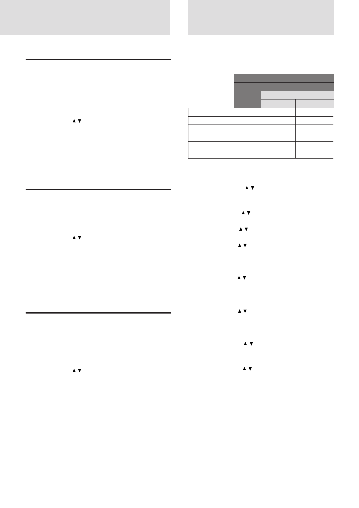
The picture elements such as brightness, contrast, white balance,
and so on can be adjusted individually for each input source. The
adjustable items vary depending on the input source and “INPUT
MODE” setting (see page 24).
Input source
(The elements
marked with “•” are
adjustable.)
BRIGHTNESS • • •
CONTRAST • • •
COLOR • – •
TINT • – •
SHARPNESS • – –
WHITE BALANCE • • •
VIDEO
S-VIDEO
INPUT MODE (See page 24.)
RGB
RGB
YCbCr
1 Select the input source (see page 16 or 21).
2 Press MENU to display the main menu.
3 Press the cursor / key to select “IMAGE ADJ
MENU.”
4 Press L-CLICK to display the IMAGE ADJ MENU.
5 Press the cursor / key to select “BRIGHTNESS,”
then press the cursor +/– key to adjust the brightness.
6 Press the cursor / key to select “CONTRAST,” then
press the cursor +/– key to adjust the contrast.
7 Press the cursor / key to select “COLOR,” then press
the cursor +/– key to adjust the color.
If the input source is RGB and “INPUT MODE” is
“RGB,” skip this step and go to step 10.
8 Press the cursor / key to select “TINT,” then press the
cursor +/– key to adjust the tint.
Note
The tint control doesn’t operate with a PAL or SECAM source.
9 Press the cursor / key to select “SHARPNESS,” then
press the cursor +/– key to adjust the sharpness.
If the input source is RGB, skip this step and go to the
next step.
10 Press the cursor / key to select “WHITE BAL-
ANCE,” then press L-CLICK.
The WHITE BALANCE menu appears.
11 Press the cursor / key to select each item in the
WHITE BALANCE menu, then press the cur sor +/– key
to adjust the item for the white color balance.
E – 27
Page 28

Selecting the
picture type
Activating the power
saving function
The picture types can be selected individually for each input source
according to the video content and your preferences.
1 Select the input source (see page 16 or 21).
2 Press MENU to display the main menu.
3 Press the cursor / k ey to select “IMAGE ADJ MENU.”
4 Press L-CLICK to display the IMAGE ADJ MENU.
5 Press the cursor / key to select “IMAGE MODE.”
6 Press L-CLICK to display the IMAGE MODE menu.
7 Press the cursor / key to select “GAMMA, ” then press
the cursor +/– key to select the gamma mode.
The following three types of gamma modes can be se-
lected according to your preferences:
• NORMAL,
• NATURAL 1, or
• NATURAL 2.
8 Press L-CLICK.
9 Press the cursor / key to select “INPUT MODE,” then
press the cursor +/– key to select the input mode.
If the input source is RGB, refer to “Setting INPUT
MODE to YCbCr” on page 24.
If the input source is VIDEO or S-VIDEO, the following
two types can be selected:
• GRAPHICS for displaying a graphic image, or
• TEXT for displaying a text image such as the image
from the document camera.
10Press L-CLICK.
11Press the cursor / key to select “WHITE PICTURE,”
then press the cursor +/– key to select the white picture
mode.
The following two types can be selected:
• NORMAL, or
• QUIET to reduce brightness for better color e xpression,
12 Press L-CLICK.
This function operates only with an RGB input source.
If the input signals from the RGB IN connector go down for more
than five minutes, the unit will automaticall y turn off and enter the
standby mode.
1 Press MENU to display the main menu.
2 Press the cursor / key to select “POWER MENU.”
3 Press L-CLICK to display the POWER MENU.
4 Press the cursor / key to select “POWER OFF,” then
press the cursor + key to select “ON” to activate the
power saving function.
To deactivate the function, set “POWER OFF” to “OFF”
by pressing the cursor – key.
Quick starting
the unit
The unit can be turned on just by only switching on the main power
on the unit (see step 1 on page 16). There is no need to press the
POWER ON button on the r emote control or the POWER button on
the unit.
1 Press MENU to display the main menu.
2 Press the cursor / key to select “POWER MENU.”
3 Press L-CLICK to display the POWER MENU.
4 Press the cursor / key to select “AUTO START,” then
press the cursor + key to select “ON” to activate the
function.
To deactivate the function, set “AUTO START” to “OFF”
by pressing the cursor – key.
Selecting the wide
screen display
1 Carry out the steps 1 to 6 above.
2 Press the cursor / key to select “DISPLAY MODE,”
then press the cursor +/– key to select “WIDE” for wide
screen display or “NORMAL” for normal screen display .
E – 28
Page 29
Activating the on–
Checking hours
screen function
If you activate the on-screen function,
• The input source “VIDEO,” “S-VIDEO,” or “RGB” will be
displayed for three seconds when you have selected the input
source with the remote control (see page 16), and
• The message “POWER OFF/ENTER” will be displayed on the
screen when you press the POWER button on the unit, if “DISPLAY” is set to “ON” for preventing the unit from being turned
off accidentally.
1 Press MENU to display the main menu.
2 Press the cursor / key to select “SETTING MENU.”
3 Press L-CLICK to display the SETTING MENU.
4 Press the cursor / key to select “DISPLA Y,” then press
the cursor + key to select “ON” to activate the on-screen
function.
To deactivate the function, set “DISPLAY” to “OFF” by
pressing the cursor – key.
Turning off the unit
• Operating with the remote control
Press the POWER OFF button a little bit longer.
The unit will go off regardless of the “POWER OFF” setting.
• Operating with the unit
When “DISPLAY” is set to “ON”
1 Press the POWER button.
“POWER OFF/ENTER” appears on the screen.
2 Press ENTER.
The unit will go off.
When “DISPLAY” is set to “OFF”
Press the POWER button a little bit longer.
The unit will go off.
of lamp use
The lamp housing must be replaced after 1000 hours of use. When
1000 hours have elapsed the STATUS indica tor will light in red (see
page 31). Periodically check hours of lamp use in the menu so that
you will have time to purchase a new lamp housing before the old
one is burnt out.
1 Press MENU to display the main menu.
2 Press the cursor / key to select “POWER MENU.”
3 Press L-CLICK to display the POWER MENU.
4 Press the cursor / key to select “LAMP USAGE.”
The lamp use hours will be displayed.
Resetting the lamp use hours to zero
Y ou need to r eset the lamp use hours to zero after replacing the lamp
housing (see page 32).
1 Carry out the steps above.
2 Pr ess the POWER ON button on the remote control for
more than ten seconds.
“LAMP USAGE” will be set to zero.
If the unit doesn’t go on because lamp
use exceeds 1100 hours.
The unit is designed not to turn on after the lamp use has exceeded
1100 hours. (If the unit is in use, it will go off.) If this happened you
must replace the lamp housing with a new one immediately. After
replacing the lamp housing, you need to reset the lamp use hours to
zero to enable you to turn on the unit.
1 Switch on the main power (see step 1 on page 16).
2 Press the POWER OFF button on the remote control for
more ten seconds.
“LAMP USAGE” will be reset to zero and the STATUS
indicator will go off (see page 31).
Canceling turing off the unit when
“POWER OFF/ENTER” is appearing on the
screen
• Operating with the remote control
– Press MAGNIFY – to turn off the message, or
– Press MENU to display the main menu.
• Operating with the unit
– Press ADJUST + to change the message on the screen to
“POWER OFF/CANCEL,” then press ENTER, or
– Press MENU to display the main menu.
Resetting all to the
factory settings
All the menu items and CUSTOM 1 to 5 memory can be reset to the
factory settings except for the followings:
• LANGUAGE
• LAMP USAGE
1 Press MENU to display the main menu.
2 Press the cursor / key to select “SETTING MENU.”
3 Press L-CLICK to display the SETTING MENU.
4 Press the cursor / key to select “ALL RESET.”
5 Press the cursor + key for more than three seconds.
“COMPLETE” appears under the title “ALL RESET”
after the reset has completed.
E – 29
Page 30
Others
Troubleshooting
This section helps you resolve problems you may encounter while setting up or using your UP-880 Data Projector.
Common Problems & Solutions
Problem
Does not turn on
No picture
Image isn’t square to the screen
Picture is blurred
Check These Items
• Check that the cord is plugged in and that the power switch on the back panel is
on. (See page 16.)
• Check the status light to see if the projector has overheated or the lamp usage
exceeds 1100 hours. (See pages 31, 29, and 32.)
• Use the menu icons to select your source (Video, S-Video, or RGB). (See page
21.)
• Ensure your cables are connected properly. (See pages 11 to 15.)
• Adjust the brightness and contrast. (See page 27.)
• Remove the lens cap. (See page 16.)
• Is the STATUS indicator blinking? (See page 31.)
• Reposition the projector to improve its angle to the screen. (See page 16.)
• Adjust the focus. (See page 17.)
• Reposition the projector to improve its angle to the screen. (See page 16.)
• Ensure that the distance between the projector and screen is within the adjustment
range of the lens. (See pages 9 and 10.)
Remote control does not work
The STATUS indicator is lit or
blinking
Cross color in RGB mode
• Install new batteries. (See page 5.)
• Make sure there are no obstacles between you and the projector.
• Stand within 13 feet (4m) of the projector. (See page 5.)
See the Status Light message chart on the next page.
If “Auto Picture” is off, turn it on. If “Auto Picture” is on, turn it off and balance
the image with the Picture Adjustment icon and Fine Picture Adjustment icon.
(See page 26.)
E – 30
Page 31
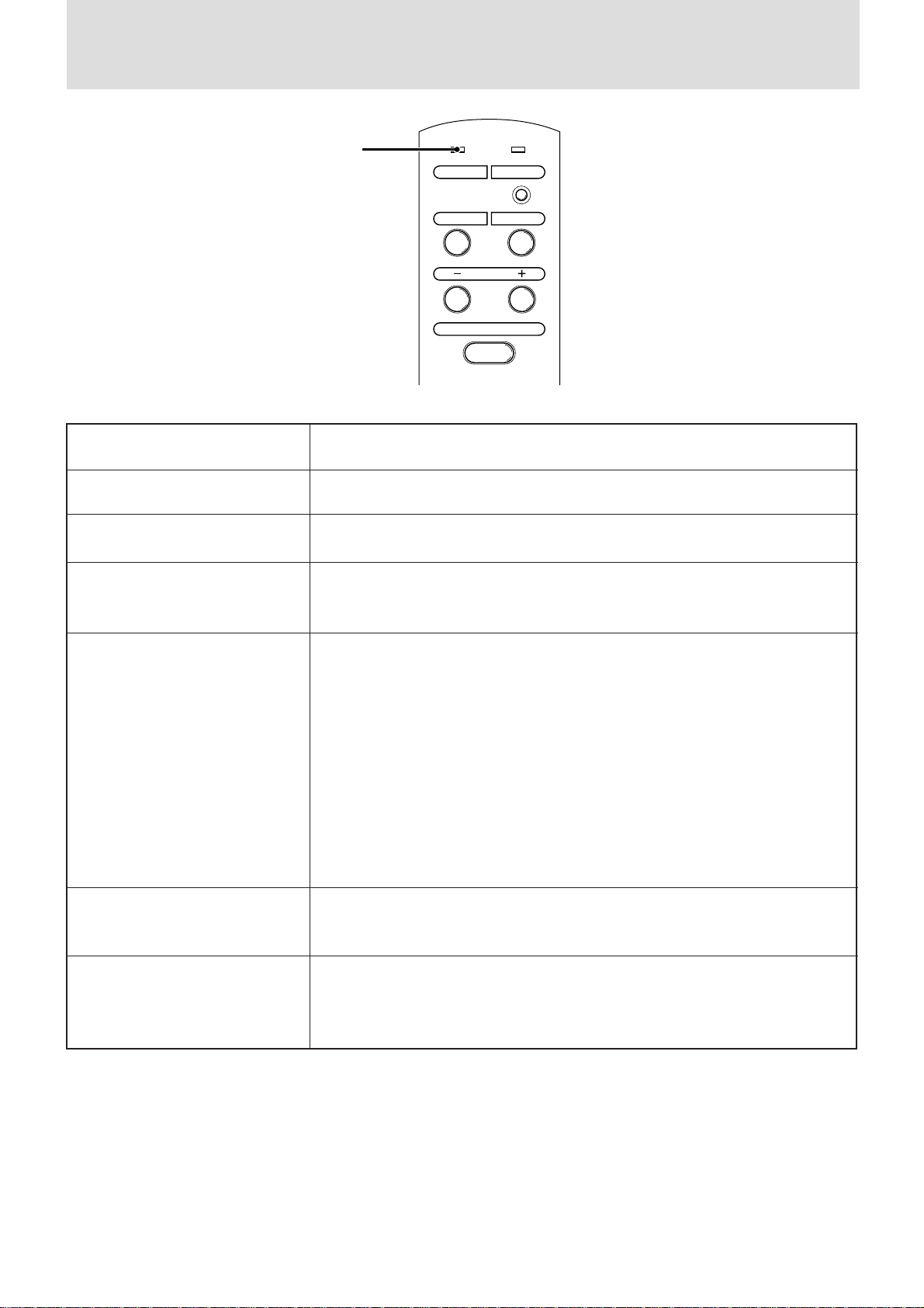
When the STATUS indicator lights or blinks
STATUS indicator
STATUS
Status Light Messages
POWER
MENUSELECT
ADJUST
ENTER
Condition
OFF
On Continually
Blinking Very Rapidly (On and off
in a cycle of 1 sec.)
Blinking Rapidly
(On and off in a cycle of 4 sec.)
Status
Normal
The projector lamp has exceeded 1000 hours of operation and should be replaced.
• The lamp housing is not correctly installed. Install it correctly.
• The temperature protector has been triggered. If the room temperature is high,
move the projector to a cool location. If the temperature within the projector is
high, check the cooling fan ventilation hole and the ventilation hole on the bottom
of the projector. If any of the holes are blocked, remove whatever is blocking them.
• The temperature protector has been triggered. If you switch the main Power switch
Off, then immediately switch it On a gain, sometimes the power does not come on. If
this happens, wait one minute, then switch the power On again.
• The lamp lighting voltage error detection protector has been triggered. Wait at
least one minute before switching it on again. If this does not solve the problem,
please contact your dealer.
Blinking Slowly (On and off in a
cycle of 8 sec.)
Blinking Very Slowly (On and off in
a cycle of 12 sec.)
The cooling fan has stopped. Contact your PLUS dealer for service.
The lamp is not turned on.
• The projector was turned off and back on too quickly. Turn off the projector, wait
one minute, then turn the projector back on. Or the lamp is burnt out.
E – 31
Page 32
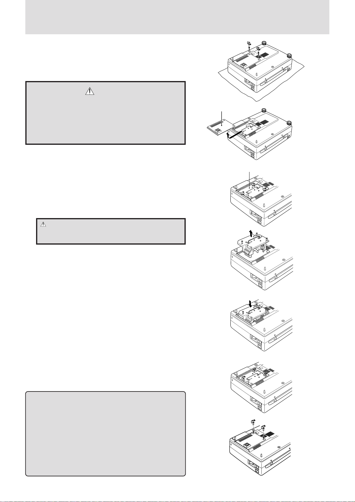
Replacing the lamp housing
After the lamp has been operating for 1000 hours or longer, the STATUS
indicator on the control panel will light and “LAMP USAGE” icon which
shows hours of total lamp use will be displayed on the screen. When this
happen, turn off the unit and replace the lamp housing with new one. The
unit will not be go on after 1100 hours. (It will go off if it is in use.)
CAUTION
• DO NOT TOUCH THE LAMP immediately after it has been
used. It will be extremely hot. Allow at least one hour for the
lamp to cool before handling.
• DO NOT LOOSEN ANY SCREWS except for those mentioned in the instructions below. There is danger of electric
shock.
Lamp Cover
Step 3
Lamp housing replacement procedure
1 Switch off the main power and unplug the power cord.
Wait at least one hour for the lamp to cool.
2 Turn the unit upside down carefully.
3 Loosen the lamp cover securing screw.
4 Slide the lamp cover in the direction of the arrow and remove it.
CAUTION: Do not use a lamp housing other than the PLUS
replacement lamp housing. Order this from your PLUS dealer
using your projector's model number (see “Notes” below).
5 Loosen the three lamp housing securing screws.
(This projector has a safety switch.)
6 Hold the handle then pull the lamp housing upwar d to remove
it.
7 Install the new lamp housing.
8 Secure the lamp housing with the three screws.
9 Replace the lamp cover and secure it with the securing screw.
10 Return the unit to the normal position, connect the power cord,
and turn on the unit.
11 Reset the lamp time.
Select the lamp usage time menu, then press the POWER ON
button on the remote control and hold it down for at least ten
seconds. (See page 29.)
Lamp housing
Step 4
Step 5
Step 6
Step 7
Notes
• When the lamp usage time reaches 1100 hours, it becomes
impossible to switch on the power and menus are not displayed.
In such a case, press the remote control POWER OFF button for
at least 10 seconds in the standby mode. It is possible to confirm
whether it has been reset or not by checking whether the STATUS
indicator is extinguished (See page 29).
• Obtain a replacement lamp at the store where the Data Projector
was purchased. When ordering a replacement lamp, specify the
UP-880 special replacement lamp - model name UP-280DC
(Product code 28-685).
E – 32
Step 8
Step 9
Page 33

Specifications
This section provides technical information about the UP-880 Data Projector's performance.
Optical
TM
DMD
Single Chip Digital Micro Device (DMDTM), 800×600 dots
Lens Manual zoom, manual focus
F 3.0 f =27.5 to 35.75 mm
Lamp Metal halide lamp 280 W
Image Size 610 to 7620 mm (24 to 300 inches) diagonal
Projection Distance 1.2 to 12.3m
Light Output 800 ANSI lumens ( normally white)
Contrast Ratio 500 : 1
Color Temperatur e 7000 Kelvin
Electrical
Inputs Video (NTSC / PAL / SECAM / NTSC4.43)
RGB (H:15 to 60 kHz, V: 50 to 85 Hz)
Video Bandwidth 60 MHz
Color Reproduction Full color, 16.7 million colors simultaneously.
Horizontal Resolution NTSC 500, PAL 500, SECAM 300, NTSC4.43 350 TV lines
RGB 800 dots horizontal, 600 dots vertical
Power Requirement 100 to 120/220 to 240 VAC, 50/60 Hz
Input Current 6 A/3A (400W)
Mechanical
Dimensions 23.5 cm (W) x 12.2 cm (H) x 32.5 cm (D)
Net Weight 4.5 kg/9.99 lbs
Operational Temperatures Data projector: 5° to 35°C (41° to 95°F), 30 to 85% humidity
Remote control: 0° to 60°C (32° to 140°F)
Remote mouse receiver: 0° to 60°C (32° to 140°F)
Regulations UL Approved (UL 1950, CSA 950)
Meets DOC Canada requirements
Meets FCC Class A requirements
Meets EMC Directive (EN55022, EN61000-3-2, EN61000-3-3, EN50082-1)
Meets Low Voltage Directive (EN60950, TÜV GS Approved)
E – 33
Page 34
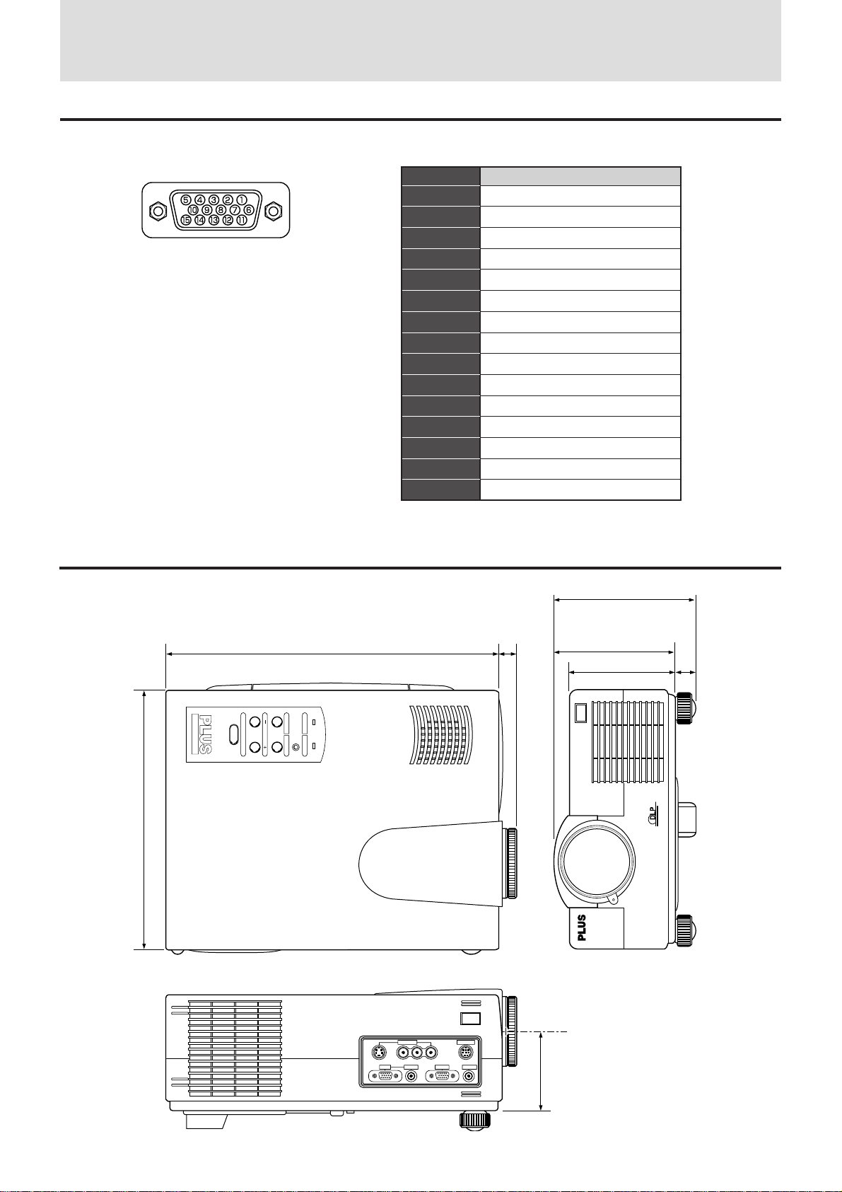
Specifications (continued)
D-Sub Pin Assignments
PC 15-Pin mini D-Sub
Dimensions
Pin No.
1
2
3
4
5
6
7
8
9
10
11
12
13
14
15
Signal to be connected
Red
Green
Blue
GND
GND
Red GND
Green GND
Blue GND
No Connection
Digital GND
GND
No Connection
Horizontal Sync
Vertical Sync
No Connection
235
UP-880
(122)
310
STATUS
ADJUST
ENTER
MENUSELECT
POWER
15
(105)
98 17
VIDEO IN
VIDEOS-VIDEO L/MONO·AUDIO·R
E – 34
PC CONTROL
AUDIO OUT
RGB OUTRGB IN AUDIO IN
85.5
 Loading...