

Page 1
U5-632h/U5-732h
U5-532h
/
U5-512h
(
U5-632h
)
(
U5-732h
)
(
U5-532h/U5-512h
)
R
G
B
STANDBY
V
ID
E
O
F
R
E
E
Z
E
M
U
T
E
E
C
O
A
U
T
O
A
S
P
E
C
T
T
IM
E
R
V
O
L
KS
T
N
Z
O
O
M
CA
NC
E
L
QU
IC
K
M
E
N
U
E
N
T
ER
Q
1234
F
R
E
E
Z
E
M
U
T
E
L
A
S
E
R
A
U
T
O
T
IM
E
R
R
G
B
V
ID
E
O
R
-C
L
IC
K
/
C
A
N
C
E
L
Q
U
IC
K
M
E
N
U
E
N
T
E
R
S
T
A
N
D
B
Y
Q
12
3
4
V
O
L
ZO
O
M
STAN
DBY
STA
TU
S
STA
N
D
B
Y
A
U
T
O
S
O
U
R
C
E
STANDBY
STATUS
STANDBY
A
UTO
SOU
RCE
F
R
E
E
Z
E
M
U
T
E
LA
S
E
R
A
U
T
O
TIM
E
R
R
G
B
V
ID
E
O
R-CLICK/
CANCEL
Q
U
IC
K
M
E
N
U
E
N
TE
R
S
TAN
D
B
Y
Q
12
3
4
V
O
L
Z
O
O
M
S
T
A
N
D
B
Y
S
T
A
T
U
S
STAN
DBY
AU
TO
SOU
RCE
IMPORTANT
* DLP™ (Digital Light Processing) and DLP™ chip are registered trademarks of Texas Instru-ments Incorporated (U.S.A.).
* DLP™ chip is an ultra-precise part developed by Texas Instruments (U.S.A.) which takes the place of liquid crystal (in
the projector).
* VGA and XGA are trademarks or registered trademarks of International Business Machines Corporation (U.S.A.).
* S-VGA is a registered trademark of Video Electronics Standards Association.
* Microsoft, Windows, and PowerPoint are registered trademarks of Microsoft Corporation (U.S.A. and other countries).
* Macintosh is a trademark of Apple Computer Inc. (U.S.A.).
Note that even in the absence of explanatory notes, serious attention is paid to the trademarks of the various companies
and to the product trademarks.
DATA PROJECTOR
U5-632h/U5-732h
U5-532h/U5-512h
User’s Manual
Page 2
E-2
Precautions
Please read this manual carefully before using your PLUS Data Projector and keep the manual handy for future reference.
This User’s Manual applies to the U5-632h, U5-732h, U5-532h and U5-512h Data Projectors. The resolution differs from model to
model, and not all models have the high brightness black/white mode or the PC mouse function. This User’s Manual describes the
U5-632h (the full-function model). Also note that the included remote control unit differs from model to model.
Please check the resolution, functions and type of remote control unit on the table below.
IMPORTANT SAFETY INFORMATION
U5-632h
U5-732h
U5-532h
U5-512h
1024⳯768 (XGA)
1024⳯768 (XGA)
1024⳯768 (XGA)
800⳯600 (S-VGA)
Model Resolution (Full Functions)
嘷: Function included ⳮ: Function not included
嘷
ⳮ
嘷
ⳮ
Black/White
mode
Wireless remote control unit with laser pointer (w/ PC
mouse function)
Wireless remote control unit (w/o laser pointer or PC
mouse function)
Type of included remote control unit
Applicable projectors will be indicated by Applicable Projector: U5-XXX placed at the description location.
CAUTION
TO PREVENT SHOCK, DO NOT OPEN THE CABINET. NO USER-SERVICEABLE PARTS INSIDE. REFER SERVICING
TO QUALIFIED PLUS SERVICE PERSONNEL.
This symbol warns the user that uninsulated voltage within the unit may have sufficient magnitude to cause electric
shock. Therefore, it is dangerous to make any kind of contact with any part inside of this unit.
This symbol alerts the user that important literature concerning the operation and maintenance of this unit has been
included. Therefore, it should be read carefully in order to avoid any problems.
The above cautions are given on the bottom of the product.
WARNING
TO PREVENT FIRE OR SHOCK, DO NOT EXPOSE THIS UNIT TO RAIN OR MOISTURE. DO NOT USE THIS UNIT’S
GROUNDED PLUG WITH AN EXTENSION CORD OR IN AN OUTLET UNLESS ALL THREE PRONGS CAN BE FULLY
INSERTED. DO NOT OPEN THE CABINET. THERE ARE HIGH-VOLTAGE COMPONENTS INSIDE. ALL SERVICING MUST
BE DONE BY QUALIFIED PLUS SERVICE PERSONNEL.
CAUTION
Do not look at the laser pointer’s light source.
Be sure to heed the following. Pointing the laser beam at
the eyes could lead to reduced vision or vision impairment.
• Never look at the laser pointer’s light source.
• Do not point the laser beam at people.
• Do not let children use the laser pointer.
This label is located on the side of the remote control.
Applicable Projector: U5-632h/U5-732h
Hg: Lamp in This Product Contains Mercury. Dispose of Lamp According to Local, State or Federal Law.
WARNING
This is a class A product. In a domestic environment this product may cause radio interference in which case the user may
be required to take adequate measures.
RF Interference
WARNING
The Federal Communications Commission does not allow any modifications or changes to the unit EXCEPT those specified by
PLUS Vision in this manual. Failure to comply with this government regulation could void your right to operate this equipment.
This equipment has been tested and found to comply with the limits for a Class A digital device, pursuant to Part 15 of the FCC
Rules. These limits are designed to provide reasonable protection against harmful interference when the equipment is operated
in a commercial environment. This equipment generates, uses, and can radiate radio frequency energy and, if not installed and
used in accordance with the instruction manual, may cause harmful interference to radio communications. Operation of this
equipment in a residential area is likely to cause harmful interference in which case the user will be required to correct the
interference at his own expense.
DOC Compliance Notice
This Class A digital apparatus meets all requirements of the Canadian Interference-Causing Equipment Regulations.
Page 3

E-3
Important Safeguards
These safety instructions are to ensure the long life of the unit and to prevent fire and shock. Please read them
carefully and heed all warnings.
Installation
• For best results, use the unit in a darkened room.
• Place the unit on a flat, level surface in a dry area away from dust and moisture.
• Do not place the unit in direct sunlight, near heaters or heat radiating appliances.
• Exposure to direct sunlight, smoke or steam can harm internal components.
• Handle the unit carefully. Dropping or jarring can damage internal components.
• Do not place heavy objects on top of the unit.
Power Supply
• The unit is designed to operate on a power supply of 100 – 120/220 – 240 V 50/60 Hz AC. Ensure that your
power supply fits these requirements before attempting to use the unit.
• Handle the power cable carefully and avoid excessive bending. A damaged cord can cause electric shock or
fire.
• Disconnect the power cable (mains lead) from the power outlet after using the unit.
Before disconnecting the power cable, make sure that the STANDBY indicator lights in amber (not blinking or
in green).
Cleaning
• Disconnect the power cable (mains lead) from the unit.
• Clean the cabinet of the unit periodically with a damp cloth. If heavily soiled, use a mild detergent. Never use
strong detergents or solvents such as alcohol or thinner.
• Use a blower or lens paper to clean the lens, and be careful not to scratch or mar the lens.
• Clean the ventilation slots and speaker grills on the unit periodically using a vacuum cleaner. If accumulated
dust blocks the ventilation slots, the unit will overheat, which may cause the unit to malfunction.
Use a soft brush attachment when using the vacuum cleaner. Do not use a hard attachment, such as a crevice
tool, to prevent the damage to the unit.
Lamp Replacement
• Be sure to replace the lamp when the Status indicator comes on. If you continue to use the lamp after 2000
hours of usage, the lamp will turn off.
Fire and Shock Precautions
• Ensure that there is sufficient ventilation and that vents are unobstructed to prevent the buildup of heat inside
the unit. Allow at least 10 cm (3 inches) of space between the unit and walls.
• Prevent foreign objects such as paper clips and bits of paper from falling into the unit. Do not attempt to retrieve
any objects that fell into the unit. Do not insert any metal objects such as a wire or screwdriver into the unit. If
something should fall into the unit, immediately disconnect the power cable from the unit and have the object
removed by a qualified PLUS service person.
• Do not place any liquids on top of the unit.
Cautions on Handling the Storage Case
• Do not put anything other than the unit or its accessories in the storage case. Paper clips, staples or other metal
or foreign objects getting inside could cause fire or electric shock.
• Do not swing the storage case around when the unit is inside. Also do not force objects that are too large to fit
into the storage case. Doing so could scratch or damage the unit.
When Moving the Unit
• When moving the unit to a different place, put it in the included storage case and place the storage case in an
insulating package to protect against falls and shocks.
• If there are paper clips, staples or other metal or foreign objects inside the storage case, the objects could get
inside the unit while the unit is being moved, causing fire or electric shock when the power is turned on.
CAUTION – HOT!
The area around the exhaust vents is hot during and immediately after image projection.
To avoid burns, keep your hands away from this area.
Wait until the exhaust vents area cools off before touching it.
Do not look into the lens while the unit is on. Serious damage to your eyes could result.
IMPORTANT SAFETY INFORMATION
Page 4

E-4
Major Features
䡵 Lightweight high-intensity projector
The synergy of the DLP™ (Digital Light Processing) display system and our own optical design serve to improve the optical
utilization efficiency. The three primary colors (RGB) required in color expression are reproduced with one DLP™ chip. These
factors have enabled a design that offers both high intensity and small size/lightweight features.
䡵 Sharp, clear picture
The DLP™ display system affords RGB color fidelity and inconspicuous gaps between the individual dots, thereby permitting
the display of small characters and diagrams with distinct clarity.
䡵
Industry’s first B/W mode for switching from the color mode to an image with a stronger brightness
Applicable Projector: U5-632h/U5-532h
When projecting documents, spreadsheets or other mostly black and white data, the image can be projected with stronger
brightness than in the color mode by switching to the “Color B/W Switching” in the menu settings. This function is a first for a
projector, and takes advantage of the features of high contrast rate DLP projectors.
䡵 Powerful functions for presentations
A wide variety of easy-to-set functions have been built into the projector, from a digital keystone correction function (used
when making settings) that corrects picture distortion, to an auto adjustment function that automatically identifies the PC
signal.
A presentation timer that supports presentations and a security lock function protecting against unauthorized projection have
also been added.
䡵 High contrast ration of 2000:1
Use of a new generation of DLP™ chip devices has given birth to an amazing 2000:1 high contrast ratio.
By widening the difference of brightness between black and white, you can see a degree of sharpness that is greater than just
the brightness based on specifications.
䡵 Beautiful reproduction of high-quality images from DVD
Faithful reproduction of color tones gives rise to the display of natural images. High-quality images such as those from DVD
and digital high-definition television broadcasts bring out the display capabilities that are an essential strength of the DLP™
display system projector.
䡵 Econo-mode switch function for the lamp output
Using the lamp Econo-mode will extend the life of the lamp and lower the power consumption.
By switching the lamp mode to suit your operating environment, you will save on lamp cost as well as contribute to energy
conservation and ecology.
Page 5

E-5
Table of Contents
IMPORTANT SAFETY INFORMATION ................................................................................... E-2
Major Features ....................................................................................................................... E-4
Table of Contents ................................................................................................................... E-5
Checking the Supplied Accessories .................................................................................... E-7
Names of the Main Unit Parts ............................................................................................... E-9
Names of the Remote Control Parts/Preparing the Remote Control .............................. E-11
Names of Parts/Preparing the Remote Control Unit
Included with the U5-632h and U5-732h ................................................................... E-11
Names of Parts/Preparing the Remote Control Unit
Included with the U5-532h and U5-512h ................................................................... E-12
Remote Control Range ............................................................................................. E-12
The Procedure Up to Projecting to the Screen ................................................................. E-13
Placement Guide .................................................................................................................. E-14
U5-632h Screen Size and Projection Distance ......................................................... E-14
U5-732h Screen Size and Projection Distance ......................................................... E-15
U5-532h/U5-512h Screen Size and Projection Distance .......................................... E-16
Connecting Personal Computers and Video Equipment .................................................. E-17
Connections with Personal Computer ....................................................................... E-17
Connect the projector’s RGB connector using the included RGB signal cable. .. E-17
To Output the External Output Signal of a Notebook Computer ......................... E-18
Connections with Composite Signals ........................................................................ E-19
Video Equipment with VIDEO Connectors .......................................................... E-19
Video Equipment with S-VIDEO Connectors ...................................................... E-19
Connections with Component Signals ....................................................................... E-20
When the Video Equipment Has a YCbCr Connector or YPbPr Connector ........ E-20
Connections with the AUDIO Jack ............................................................................ E-21
Connections with the RGB OUT Connector .............................................................. E-22
Power Cable Connections and Switching the Power On/Off ........................................... E-23
Operating ................................................................................................................... E-23
Finishing .................................................................................................................... E-25
Adjustment of the Projection Screen ................................................................................. E-26
Adjustment of the Projection Screen ......................................................................... E-26
Making Adjustments with the Adjusters .............................................................. E-27
General Operation ................................................................................................................ E-28
Input Selection .......................................................................................................... E-28
Automatic Adjustment ............................................................................................... E-28
Selection of Aspect Ratio .......................................................................................... E-29
Freezing a Moving Picture ......................................................................................... E-30
Cancelling Video and Audio Temporarily ................................................................... E-30
Lamp Mode ............................................................................................................... E-30
Keystone.................................................................................................................... E-31
Adjustment of the Volume .......................................................................................... E-31
Enlargement of the Image and Video Movement ...................................................... E-32
Using the Presentation Timer .................................................................................... E-33
Using the Laser Pointer ............................................................................................. E-34
Performing Mouse Operations on the Computer
with the Remote Control Unit .................................................................................... E-35
Controlling the Projector from a Computer ................................................................ E-36
Use as a High-Brightness Monochrome Projector .................................................... E-36
Protecting the Projector with the Security Lock ......................................................... E-37
Using the Quick Menu ............................................................................................... E-39
Menu Operation Method ...................................................................................................... E-40
Performing Menu Operations .................................................................................... E-42
List of Item Names Offering Input Selection and Adjustments/Settings .................... E-45
Image ..................................................................................................................................... E-47
Brightness / Contrast / Color / Tint / Sharpness ........................................................ E-47
Picture Adj. / Fine Picture / H Position / V Position .................................................... E-47
Reset ......................................................................................................................... E-48
Page 6

E-6
Table of Contents
Color ...................................................................................................................................... E-49
Quick Color Adj. ........................................................................................................ E-49
Gamma ..................................................................................................................... E-49
Color Temp. ............................................................................................................... E-50
White ......................................................................................................................... E-50
Color Space .............................................................................................................. E-50
White Balance ........................................................................................................... E-51
View ....................................................................................................................................... E-52
Aspect ....................................................................................................................... E-52
Filter .......................................................................................................................... E-52
Vertical Flip ................................................................................................................ E-53
Keystone.................................................................................................................... E-53
Keystone Save .......................................................................................................... E-53
Setup ..................................................................................................................................... E-54
Color B/W Switching ................................................................................................. E-54
Auto Source............................................................................................................... E-54
Auto Power Off .......................................................................................................... E-54
Menu Position............................................................................................................ E-55
Lamp Mode ............................................................................................................... E-55
Input Format .............................................................................................................. E-56
Presentation Timer .................................................................................................... E-56
Option ................................................................................................................................... E-57
Language .................................................................................................................. E-57
On Screen ................................................................................................................. E-57
Background ............................................................................................................... E-57
Startup Screen .......................................................................................................... E-58
Security Lock ............................................................................................................. E-58
Info......................................................................................................................................... E-59
Status ........................................................................................................................ E-59
Factory Default .......................................................................................................... E-59
Lamp Timer Reset ..................................................................................................... E-59
Resolution / Frequency ............................................................................................. E-60
Lamp Timer ............................................................................................................... E-60
When an Indicator is Lit or Flashing .................................................................................. E-61
Troubleshooting ................................................................................................................... E-62
Cleaning ................................................................................................................................ E-63
Replacing the Lamp Cartridge ............................................................................................ E-64
Specifications ....................................................................................................................... E-67
Table of Supported Frequency ........................................................................................... E-71
Cabinet Dimensions ............................................................................................................ E-72
Page 7

E-7
Checking the Supplied Accessories
Remove the main unit and the accessories from the box and check that the following items are included.
Wireless remote control unit with laser pointer [1] /
Size AAA batteries [2]
Applicable Projector: U5-632h/U5-732h
This controls the projector. (See Page E-11.)
FREEZE
MUTE
LASER
AUTO
TIMER
VO
L
ZOO
M
RGB
VIDEO
R
-CLICK/
CAN
C
EL
QUICK
MENU
ENTER
STANDBY
Q
12
3
4
* The wireless remote control is sold separately for the U5-
532h and U5-512h.
VR-100 remote mouse set (sold separately)
(Ordering code: 28-052)
S-Video cable (Mini DIN 4-pin plug, 2 m / 6.6 feet) [1]
Applicable Projector: U5-632h/U5-732h/U5-532h
This cable is used in the connection of video equipment that
has an S-video connector. Connections are described on Page
E-19.
No. 777704000
Wireless remote control unit
(includes one button battery) [1]
Applicable Projector: U5-532h/U5-512h
This controls the projector. Please remove the transportation
insulation sheet at time of purchase. (See Page E-12.)
R
G
B
S
T
A
N
D
B
Y
V
ID
E
O
F
R
E
E
ZE
M
U
TE
E
C
O
A
U
TO
A
S
P
E
C
T
T
IM
E
R
V
O
LKS
TN ZO
O
M
C
A
N
C
E
L
Q
U
IC
K
M
EN
U
E
N
T
E
R
Q
1234
Video cable (RCA pin plug, 2 m / 6.6 feet) [1]
Applicable Projector: U5-632h/U5-732h/U5-532h
This cable is used in the connection of video equipment that
has a video connector. Connections are described on Page
E-19.
No. 777703000
RGB signal cable
(Mini D-sub 15-pin, 2 m / 6.6 feet) [1]
This is used in making connections with a personal computer.
See Page E-17 about connections.
No. 777709000
Audio cable (Mini plug, 2 m / 6.6 feet) [1]
Applicable Projector: U5-632h/U5-732h/U5-532h
This cable is used with equipment that has phono type audio
jacks. Connections are described on Page E-21.
No. 777705000
Power cable (1.8 m / 5.9 feet) [1]
This power cable supplies power to the unit. See Page E-23
about connections.
Audio conversion adapter (Mini-jack/ RCA pin plug, 15 cm
/ 0.5 feet) [1]
Applicable Projector: U5-632h/U5-732h/U5-532h
This cable is used with equipment whose audio connector is
of the phono pin type. Connections are described on Page
E-21.
No. 777706000
Page 8
E-8
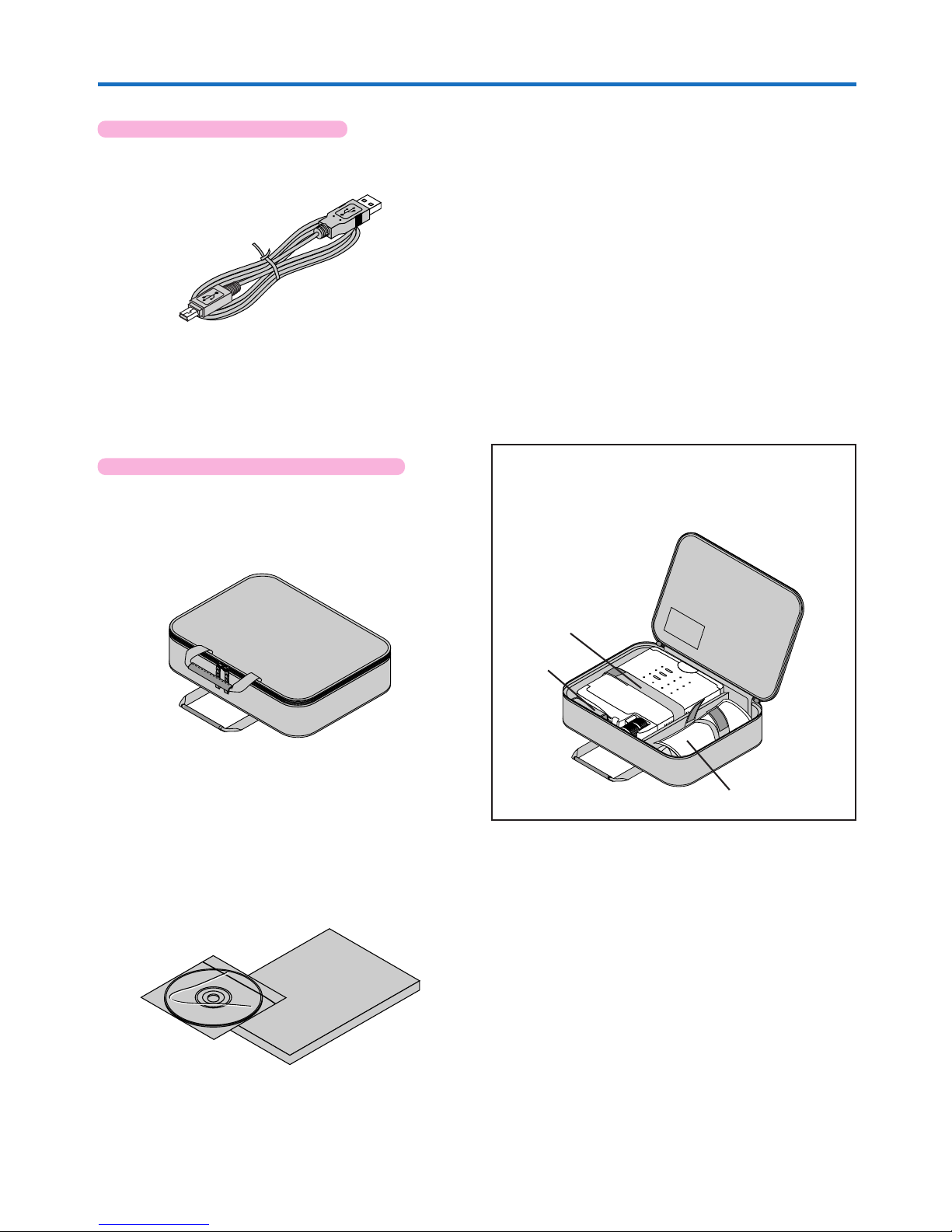
Storage case (for projector and accessories) [1]
Applicable Projector: U5-632h/U5-732h/U5-532h
This case is designed to hold the projector itself and its accessories.
Use it when storing the projector.
User’s Manual (CD-ROM edition) [1]
User’s Manual (Simplified Edition) [1]
Security Sheet [1]
Security Label [1]
HOW TO PUT THE PROJECTOR INTO THE STORAGE CASE
Close the lens shutter or lens cap before putting the projector in its case, then fasten the projector in place with the
Velcro belt. Place the accessories in the storage pocket.
Pocket
Velcro strap
Checking the Supplied Accessories
Cable storage pouch [1]
USB cable (type A, 2 m / 6.6 feet) [1]
Applicable Projector: U5-632h/U5-732h
Used to perform mouse operations on a computer using the
projector’s remote control unit. Connections are described on
Page E-35.
No. 777707000
* The wireless remote control is sold separately for the U5-
532h and U5-512h.
VR-100 remote mouse set (sold separately)
(Ordering code: 28-052)
Page 9
E-9
S
T
A
N
D
B
Y
S
T
A
T
U
S
S
T
A
N
D
B
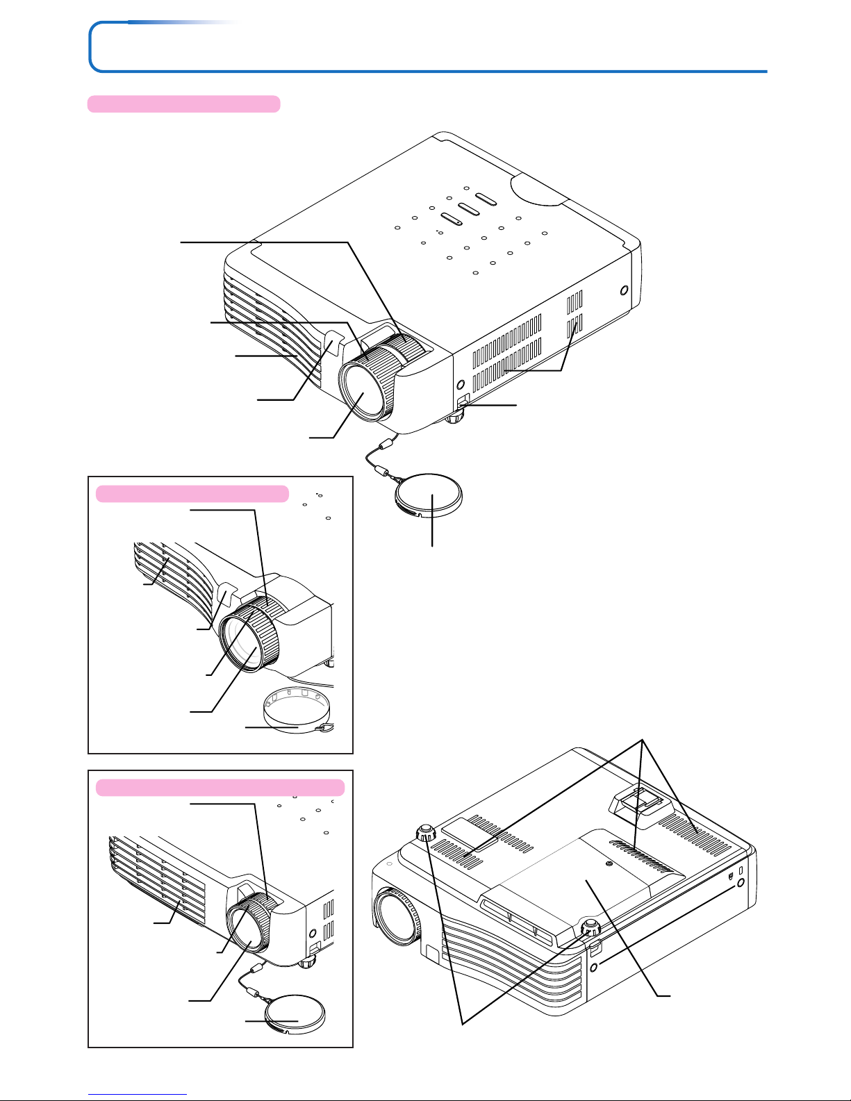
Names of the Main Unit Parts
STANDBY
STATUS
STANDBY
AUTO
SOURCE
Adjuster button [E-27]
(Also on opposite side)
Focus ring [E-27]
Lens
Exhaust vents
Adjusters [E-27]
Lamp cover [E-65]
Ventilation slots
Focus ring [E-27]
Lens cap
Remove before use. Attach
the lens cap after use to
protect the lens.
Remote control
sensor [E-12]
Lens
Zoom ring [E-26]
Applicable Projector: U5-632h
Applicable Projector: U5-532h/U5-512h
Ventilation slots
Zoom ring [E-26]
Exhaust
vents
Lens cap
S
T
A
N
D
B
S
T
A
T
U
S
Lens
Focus ring [E-27]
Zoom ring [E-26]
Exhaust
vents
Lens cap
Applicable Projector: U5-732h
Remote control
sensor [E-12]
Page 10
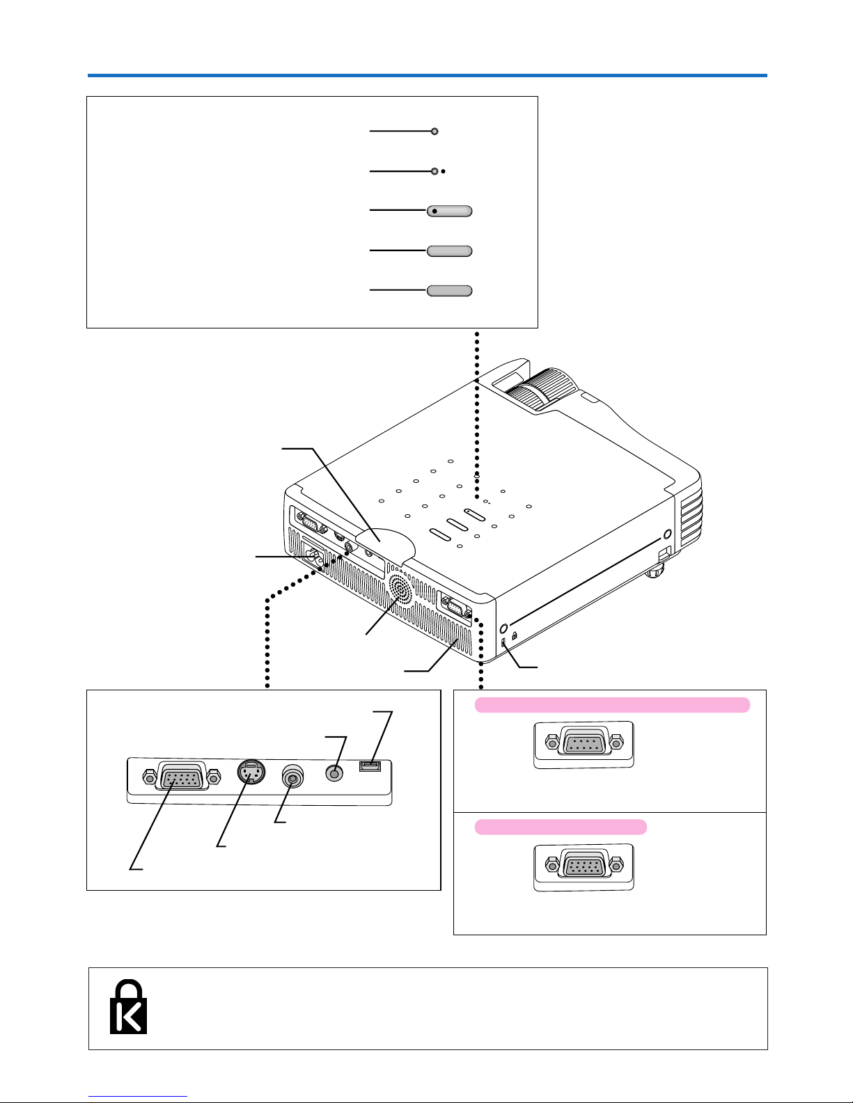
E-10
Names of the Main Unit Parts
RGB
S VIDEO
VIDEO
AUDIO
MOUSE
STANDBY
STATUS
STANDBY
AUTO
SOURCE
STANDBY
STATUS
STANDBY
AUTO
SOURCE
RGB
S VIDEO
VIDEO
AUDIO
MOUSE
P
C
C
O
N
T
R
O
L
PC CONTROL
RGB OUT
STANDBY indicator [E-23, 61]
STATUS indicator [E-23, 61]
AUTO button [E-28]
STANDBY button [E-23]
SOURCE button [E-28]
Built-in Security Slot
This security slot supports the MicroSaver Security System manufactured by
Kensington Microware Inc.
Ventilation slots
Speaker
Built-in security slot
(See description below.)
AC IN connector [E-23]
Remote control sensor [E-12]
RGB connector [E-17, 20]
S-VIDEO connector [E-19]
VIDEO connector [E-19]
AUDIO connector [E-21]
Applicable Projector: U5-632h/U5-732h/U5-532h
MOUSE connector [E-35]
PC CONTROL connector (D-Sub 9-pin) [E-36]
Applicable Projector: U5-512h
RGB OUT connector (Mini D-sub 15-pin) [E-22]
Page 11
E-11
Names of the Remote Control Parts/Preparing the Remote Control
There are two types of remote control units included with the U5 series of projectors. Both types are described below.
Refer to the description (and diagram) for the remote control unit included with your projector.
Note:
If a button on the remote control unit is held
in continuously for approximately 30 seconds,
signal transfer will be suspended. To resume
transferring signals, press the button again.
Also, to use the jog button after signal transfer has been suspended, first press any other
button, then press the jog button.
Names of Parts/Preparing the Remote Control Unit
Included with the U5-632h and U5-732h
Applicable Projector:
U5-632h/U5-732h
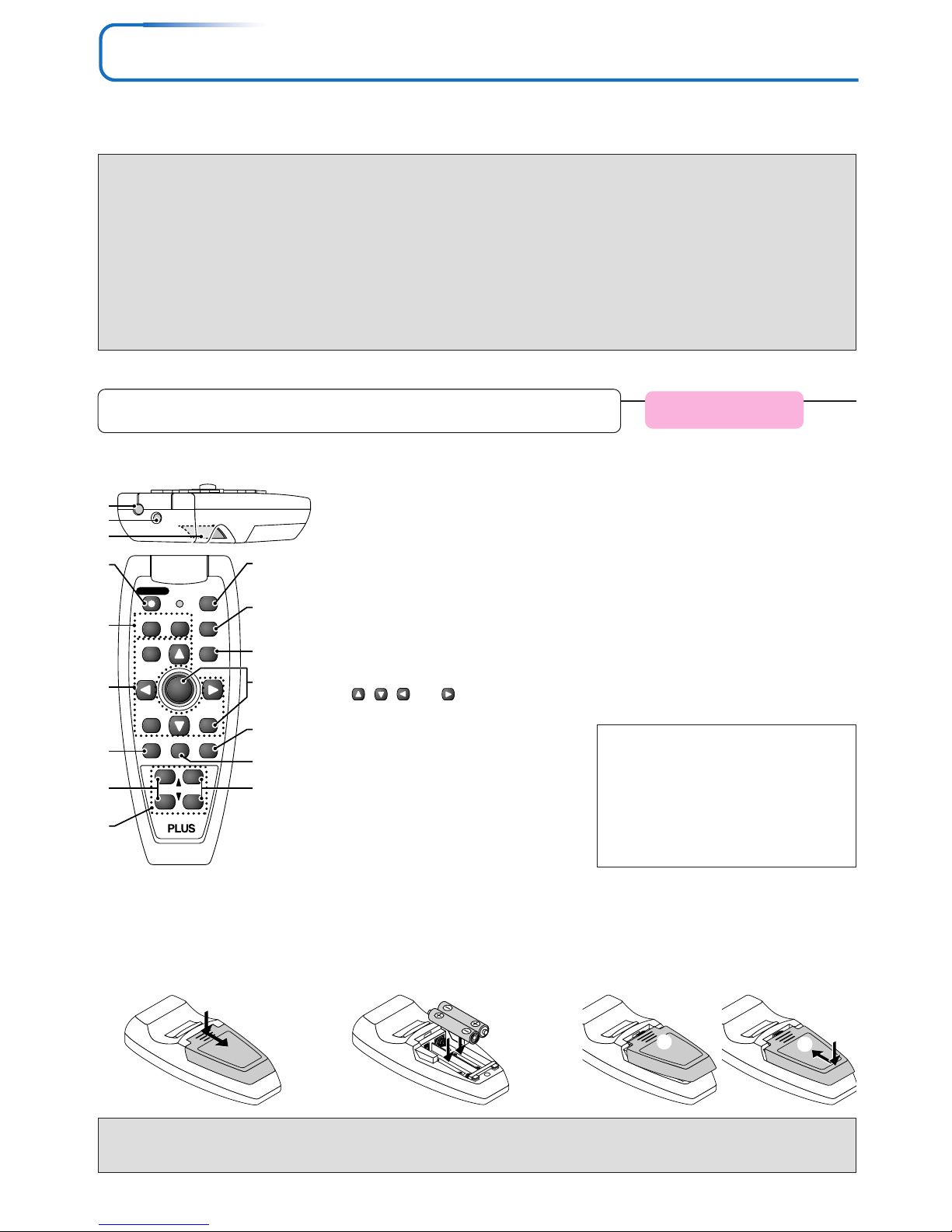
1. Infrared transmitter [E-12]
2. Laser transmitter [E-34]
3. L-CLICK button [E-35]
4. STANDBY button [E-23, 25]
This button is used to switch ON the power
and set the unit to the STANDBY mode.
5. Buttons used for input selection
[E-28]
RGB button and VIDEO button (VIDEO /
S-VIDEO)
6. Buttons used for menu operations
[E-40]
The , , and buttons are the
select (왖, 왔, 왗 and 왘) buttons.
7. FREEZE button [E-30]
(Freezes moving pictures)
8. VOL button [E-31]
(Volume adjustment)
9. Number buttons [E-37]
(Used for the security lock.)
10. LASER button [E-34]
(Turns the laser point on and off)
Names of the Remote Control Parts
FREEZE
MUTE
LASER
AUTO
TIMER
VOL
ZOOM
RGB
VIDEO
R-CLICK/
CANCEL
QUICKMENU
ENTER
STANDBY
Q
12
34
4
1
2
3
5
6
7
8
9
10
11
12
13
14
15
16
11. AUTO button [E-28]
(Automatic adjustment of the RGB moving
image)
12. QUICK button [E-39]
(Displays a simplified menu)
13. Buttons used for the PC mouse
function [E-35]
(JOG button and R-CLICK button)
14. TIMER button [E-33]
(Presentation timer time setting display)
15. MUTE button [E-30]
(Temporarily cancels the video and audio)
16. ZOOM button [E-32]
(Digital zoom adjustment)
Inserting the Batteries
When using the remote control for the first time, install the batteries that were supplied.
(B)
(C)
(A)
2
Insert the batteries to match
the “+” and “–” as indicated in-
side the compartment.
1
Slide the battery compartment
cover (located on the bottom
of the remote control) and pull
off.
3
(A) Leaving a little space in the front, close
the lid, (B) then with the back pressed tightly,
(C) press the lid towards the front.
CAUTION
When replacing batteries, purchase two of the same type of AAA battery.
Heed the regulations in effect in your region on the disposal of spent batteries.
Precautions
Handling of the Remote Control
* Do not drop the remote control or handle it inappropriately.
* Do not expose the remote control to water or other liquids. Should the remote control become wet, wipe it dry
immediately.
* Try to avoid use in hot and/or humid locations.
* Please keep button batteries out of the reach of children. If a battery is swallowed, promptly obtain the medical care
of a doctor.
* Remove the batteries from the remote control when it is not going to be used for a long period.
* Some operations (such as menu operations) are available only through the use of the remote control and attention
should be given to its careful handling.
Page 12
E-12
Names of the Remote Control Parts/Preparing the Remote Control
Names of the Remote Control Parts
Names of Parts/Preparing the Remote Control Unit
Included with the U5-532h and U5-512h
Applicable Projector:
U5-532h/U5-512h
Button Battery Replacement
Using the remote control for the first time
The battery compartment is fitted with a transportation insulation sheet at the time of shipping. Pull out
the sheet and remove it. The remote control is now ready for use.
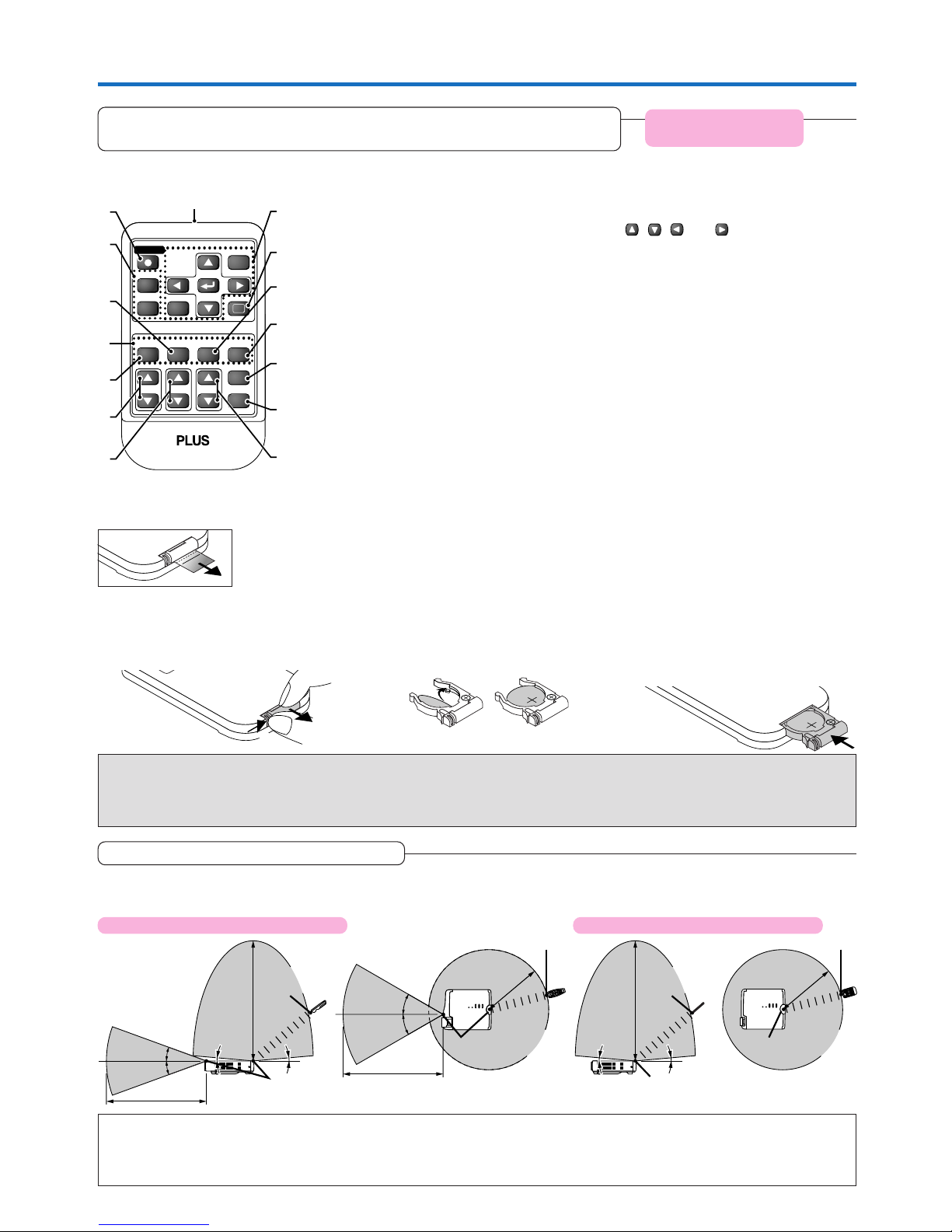
1. Infrared transmitter [E-12]
2. STANDBY button [E-23, 25]
This button is used to switch ON the power
and set the unit to the STANDBY mode.
3. Buttons used for input selection
[E-28]
RGB button and VIDEO button (VIDEO /
S-VIDEO)
4. MUTE button [E-30]
(Temporarily cancels the video and audio)
5. Number buttons [E-37]
(Used for the security lock.)
6. FREEZE button [E-30]
(Freezes moving pictures)
7. VOL button [E-31]
(Volume adjustment)
8. KSTN button [E-31]
(Keystone correction adjustment)
RGB
VIDEO
FREEZE
MUTE
ECO AUTO
ASPECT
TIMER
VOL KSTN ZOOM
CANCEL QUICK
MENU
ENTER
Q
STANDBY
1234
1
2
9
10
11
12
13
14
15
3
4
5
6
7
8
9. Buttons used for menu operations
[E-40]
The
, , and buttons are the
select (왖, 왔, 왗 and 왘) buttons.
10. QUICK button [E-39]
(Displays a simplified menu)
11. ECO button [E-30]
(Selection of lamp mode)
12. AUTO button [E-28]
(Automatic adjustment of the RGB moving
image)
13. ASPECT button [E-29]
(Selects the vertical and horizontal ratio of
the screen)
14. TIMER button [E-33]
(Presentation timer time setting display)
15. ZOOM button [E-32]
(Digital zoom adjustment)
Replacement Method
(B)
(A)
CR2025
CR2025
CR2025
Purchase a CR2025 type battery for replacement.
3
Insert the battery holder into the
remote control and push in until
the battery holder closes with a
“click” sound.
2
Remove the old battery and install
a new button battery with (+) side
facing upward in the battery
holder.
1
(A) With the knob pressed to the
right side, (B) draw out the battery
case.
CAUTION
Danger of explosion if battery is incorrectly replaced.
Replace only with the same or equivalent type (CR2025) recommended by the manufacturer.
Dispose of used batteries according to your local regulations.
Remote Control Range
Point the infrared transmitter of the remote control toward the remote control sensor located at the front or rear of the main unit
and operate. Reception of the remote control signal should generally be possible within the range illustrated below.
Note
* Exposure of the main unit’s remote control sensor or the remote control infrared transmitter to bright light or the obstruction of the signal
by an obstacle located in the pathway may prevent operation.
* The remote control will not function when the battery is exhausted.
Applicable Projector: U5-532h/U5-512hApplicable Projector: U5-632h/U5-732h
5m/16.4feet
5° 5°
6m/19.7 feet
20°
20°
3m/9.8 feet
5m/16.4feet
30°
30°
3m/9.8 feet
5° 5°
6m/19.7 feet
Side View Top View
Remote control
infrared transmitter
Remote control sensor Remote control sensor
Side View Top View
Remote control sensor
Remote control
infrared transmitter
Remote control infrared transmitter Remote control infrared transmitter
Remote control sensor
Page 13

E-13
The Procedure Up to Projecting to the Screen
Perform setup adjustments in the following order.
1 Position the projector
Determine the locations to set up the screen and the projector.
See “Placement Guide” on Page E-14.
2 Connect the video equipment and personal computer
Connect your equipment to the projector.
When making connections with the personal computer’s RGB connector, see “Connections with
Personal Computer” on Page E-17.
When making connections with the video equipment’s video connector or an S-video connector,
see “Connections with Composite Signals” on Page E-19.
When making connections with the video equipment’s YCbCr connector or YPbPr connector,
see “Connections with Component Signals” on Page E-20.
When playing the audio through the built-in speaker of the projector, see “Connections with the
AUDIO Jack” on Page E-21.
Monitoring the analog RGB input signal, see “Connections with the RGB OUT Connector” on
Page E-22.
4 Connecting the power cable and switching on the power
See “Operating” on Page E-23.
See “Finishing” on Page E-25.
5 When selecting the language of menu displays, etc.
(Only when the power is first switched on following purchase)
See “When [Menu Language Select] Is Displayed Upon Switching On the Power” on Page E-24.
6 Switching on the power of the personal computer and video equipment
7 Properly adjust the projection image to the screen
See “Adjustment of the Projection Screen” on Page E-26.
8 Selecting input equipment
See “Input Selection” on Page E-28.
9 Adjust the screen or video image
Adjust the image to the optimum condition as required.
See the Table of Contents for the adjustment items.
About DLP projectors
Though careful attention is paid to providing optimum quality, please note that with DLP type projectors, in rare cases there may
be black spots or bright spots among the picture elements.
Note:
* Please purchase a screen.
* A component cable (order code 28-690), which is available separately, is required to connect a DVD player or other equipment with YCbCr
connectors.
* A component cable (order code 28-690), which is available separately, is required to connect high definition (HD) video equipment or other
equipment with YPbPr connectors.
3 Opening the lens cap
Applicable Projector: U5-512h
Page 14
E-14
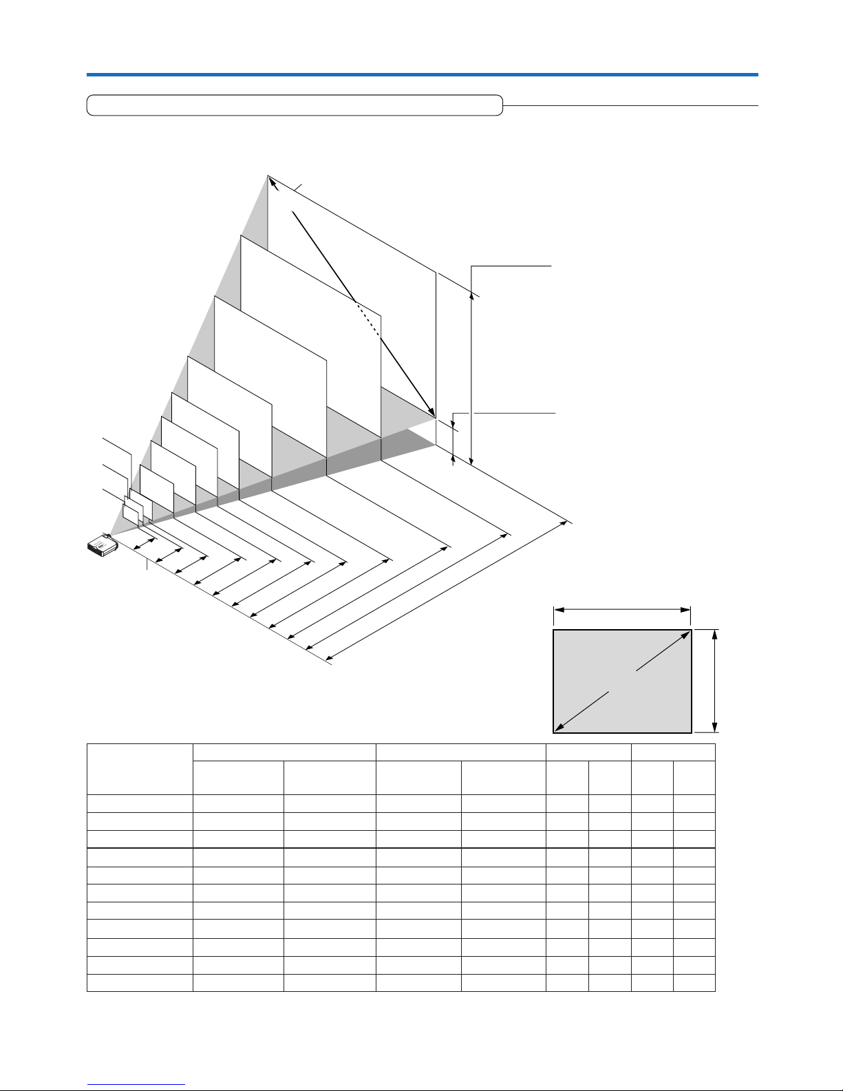
250"
200"
180"
150"
120"
100"
80"
60"
38.4"
1.20
(3.94)
1.57–1.90(5.15–6.23)
2.10
–2.54(6.89
–8.33)
2.64
–3.18(8.66
–10.43)
3.17
–3.81(10.40
–12.50)
3.97
–4.78(13.02
–15.68)
4.77
–5.73(15.65
–18.80)
5.30
–6.38(17.39
–20.93)
7.97
–9.59(26.15
–31.46)
6.64
–7.98(21.78
–26.18)
h1
h2
300"
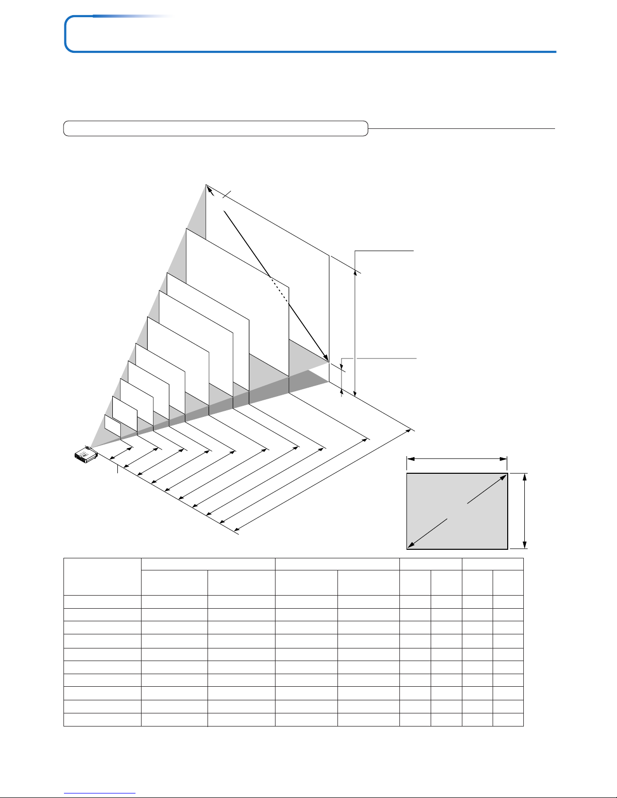
Placement Guide
• The projection distance over which focussing is adjustable is 1.20 m (3.94 feet) to 9.59 m (31.46 feet). The projector
should be placed within this range.
Height from center of
lens to bottom edge
of the projection
Height from center of
lens to top edge of
the projection
Unit: m (feet)
Lens surface of
the main unit
Screen Size Designation (Inches)
* There is a tolerance of ±5% due to design values.
* This table uses the lens apex and lens center as references and requires that the projector be in a horizontal condition
(with front and rear adjusters fully withdrawn).
38.4"
60"
80"
100"
120"
150"
180"
200"
250"
300"
0.78⳯0.59
1.22⳯0.91
1.63⳯1.22
2.03⳯1.52
2.44⳯1.83
3.05⳯2.29
3.66⳯2.74
4.06⳯3.05
5.08⳯3.81
6.10⳯4.57
—– 1.20
1.57 – 1.90
2.10 – 2.54
2.64 – 3.18
3.17 – 3.81
3.97 – 4.78
4.77 – 5.73
5.30 – 6.38
6.64 – 7.98
7.97 – 9.59
0.69
1.08
1.43
1.79
2.15
2.69
3.23
3.59
4.48
5.38
0.10
0.16
0.22
0.27
0.32
0.40
0.49
0.54
0.67
0.81
Screen Size
Designation (Inches)
Screen Size Width x Height Projection Distance Height h1 Height h2
2.56 ⳯ 1.92
4.00 ⳯ 3.00
5.33 ⳯ 4.00
6.67 ⳯ 5.00
8.00 ⳯ 6.00
10.00 ⳯ 7.50
12.00 ⳯ 9.00
13.33 ⳯10.00
16.67 ⳯12.50
20.00 ⳯15.00
(m) (feet)
—– 3.94
5.15 – 6.23
6.89 – 8.33
8.66 – 10.43
10.40 – 12.50
13.02 – 15.68
15.65 – 18.80
17.39 – 20.93
21.78 – 26.18
26.15 – 31.46
2.26
3.54
4.69
5.87
7.05
8.83
10.60
11.78
14.70
17.65
0.33
0.52
0.72
0.89
1.05
1.31
1.61
1.77
2.20
2.66
(m) (feet) (m) (feet) (m) (feet)
Wide – Tele Wide – Tele
Width
Height
Screen size (Diagonal)
• Use this information as a guide to find out about the screen size when the projector is placed at a certain location, or
to find out the approximate size of a screen that will be required.
• Refer to the projection distance table for your projector model.
• When suspending the projector from the ceiling, change the projection method. See “Vertical Flip” on E-53.
U5-632h Screen Size and Projection Distance
Page 15
E-15
Placement Guide
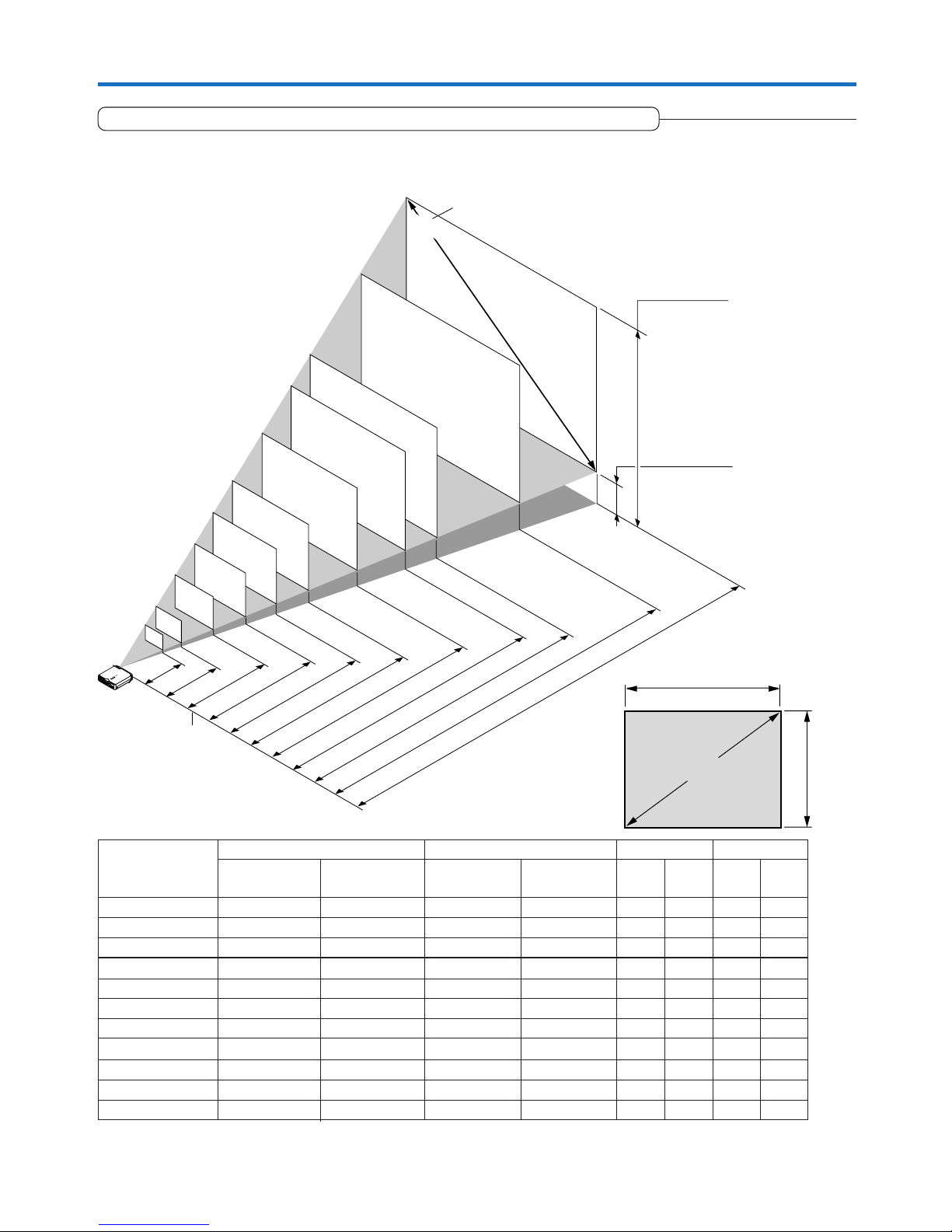
250"
200"
150"
120"
100"
80"
60"
1.49–1.80
(4.89–5.91)
1.23–1.48
(4.04–4.86)
2.26–2.73
(7.41–8.96)
3.03
–3.65(9.94
–11.98)
3.80–4.57(12.47
–14.99)
4.57–5.50(14.99
–18.04)
5.73–6.88(18.80
–22.57)
7.65–9.19(25.10
–30.15)
11.50–13.81(37.73
–45.31)
9.57–11.50(31.40
–37.73)
1.20
(3.94)
h1
h2
300"
33"
27"
40"
S
T
A
N
D
B
Y
ST
A
T
U
S
S
T
A
N
D
B
Y
A
U
T
O
S
O
U
R
C
E
R
G
B
S
V
I
D
E
O
V
I
D
E
O
A
U
D
I
O
M
O
U
S
E
P
C
C
O
N
T
R
O
L
Height from center of
lens to bottom edge
of the projection
Height from center of
lens to top edge of
the projection
Unit: m (feet)
Lens surface of
the main unit
Screen Size Designation (Inches)
• The projection distance over which focussing is adjustable is 1.20 m (3.94 feet) to 13.81 m (45.31 feet). The projector
should be placed within this range.
Width
Height
Screen size (Diagonal)
U5-732h Screen Size and Projection Distance
* There is a tolerance of ±5% due to design values.
* This table uses the lens apex and lens center as references and requires that the projector be in a horizontal condition
(with front and rear adjusters fully withdrawn).
27"
33"
40"
60"
80"
100"
120"
150"
200"
250"
300"
0.56⳯0.41
0.67⳯0.50
0.81⳯0.61
1.21⳯0.91
1.62⳯1.21
2.03⳯1.52
2.43⳯1.82
3.04⳯2.28
4.06⳯3.04
5.08⳯3.81
6.09⳯4.57
—– 1.20
1.23 – 1.48
1.49 – 1.80
2.26 – 2.73
3.03 – 3.65
3.80 – 4.57
4.57 – 5.50
5.73 – 6.88
7.65 – 9.19
9.57 – 11.50
11.50 – 13.81
0.48
0.59
0.72
1.07
1.43
1.79
2.14
2.68
3.58
4.48
5.38
0.07
0.09
0.11
0.16
0.22
0.27
0.32
0.40
0.54
0.67
0.81
Screen Size
Designation (Inches)
Screen Size Width x Height Projection Distance Height h1 Height h2
1.83 ⳯ 1.35
2.19 ⳯ 1.64
2.65 ⳯ 2.00
3.96 ⳯ 2.98
5.31 ⳯ 3.96
6.66 ⳯ 4.98
7.97 ⳯ 5.97
9.97 ⳯ 7.48
13.32 ⳯ 9.97
16.66 ⳯12.50
19.98 ⳯14.99
(m) (feet)
—– 3.94
4.04 – 4.86
4.89 – 5.91
7.41 – 8.96
9.94 – 11.98
12.47 – 14.99
14.99 – 18.04
18.80 – 22.57
25.10 – 30.15
31.40 – 37.73
37.73 – 45.31
1.57
1.94
2.36
3.51
4.69
5.87
7.02
8.79
11.75
14.70
17.65
0.23
0.30
0.36
0.52
0.72
0.89
1.05
1.31
1.77
2.20
2.66
(m) (feet) (m) (feet) (m) (feet)
Wide – Tele Wide – Tele
Page 16
E-16
Placement Guide
1.20
(3.94)
1.46–1.75(4.79
–5.74)
2.20
–2.65(7.22
–8.69)
2.94
–3.54(9.65
–11.61)
3.67
–4.43(12.04
–14.53)
4.43
–5.33(12.04
–14.53)
5.54
–6.67(18.18
–21.88)
6.67
–8.00(21.88
–26.25)
7.40
–8.90(24.28
–29.20)
9.62
–11.13(31.56
–36.52)
11.12
–13.36(36.48
–43.83)
h1
h2
250"
200"
180"
150"
120"
100"
80"
60"
40"
27.6"
300"
U5-532h/U5-512h Screen Size and Projection Distance
Height from center of
lens to bottom edge
of the projection
Height from center of
lens to top edge of
the projection
Unit: m (feet)
Lens surface of
the main unit
Screen Size Designation (Inches)
• The projection distance over which focussing is adjustable is 1.20 m (3.94 feet) to 13.36 m (43.83 feet). The projector
should be placed within this range.
* There is a tolerance of ±5% due to design values.
* This table uses the lens apex and lens center as references and requires that the projector be in a horizontal condition
(with front and rear adjusters fully withdrawn).
27.6"
40"
60"
80"
100"
120"
150"
180"
200"
250"
300"
0.56⳯0.42
0.81⳯0.61
1.22⳯0.91
1.63⳯1.22
2.03⳯1.52
2.44⳯1.83
3.05⳯2.29
3.66⳯2.74
4.06⳯3.05
5.08⳯3.81
6.10⳯4.57
—– 1.20
1.46 – 1.75
2.20 – 2.65
2.94 – 3.54
3.67 – 4.43
4.43 – 5.33
5.54 – 6.67
6.67 – 8.00
7.40 – 8.90
9.62 – 11.13
11.12 – 13.36
0.49
0.72
1.07
1.43
1.79
2.15
2.69
3.22
3.59
4.48
5.38
0.07
0.11
0.16
0.21
0.27
0.32
0.40
0.48
0.54
0.67
0.81
Screen Size
Designation (Inches)
Screen Size Width x Height Projection Distance Height h1 Height h2
1.84 ⳯ 1.38
2.67 ⳯ 2.00
4.00 ⳯ 3.00
5.33 ⳯ 4.00
6.67 ⳯ 5.00
8.00 ⳯ 6.00
10.00 ⳯ 7.50
12.00 ⳯ 9.00
13.33 ⳯10.00
16.67 ⳯12.50
20.00 ⳯15.00
(m) (feet)
—– 3.94
4.79 – 5.74
7.22 – 8.69
9.65 – 11.61
12.04 – 14.53
14.53 – 17.49
18.18 – 21.88
21.88 – 26.25
24.28 – 29.20
31.56 – 36.52
36.48 – 43.83
1.61
2.36
3.51
4.69
5.87
7.05
8.83
10.56
11.78
14.70
17.65
0.23
0.36
0.52
0.69
0.89
1.05
1.31
1.57
1.77
2.20
2.66
(m) (feet) (m) (feet) (m) (feet)
Width
Height
Screen size (Diagonal)
Wide – Tele Wide – Tele
Page 17
E-17
Connecting Personal Computers and Video Equipment
Connecting this unit with a personal computer permits presentation data to be projected as a large screen display at
conferences, lectures, and on other occasions. Furthermore, connecting this unit to a DVD player or other video equipment source in combination with an audio/video amplifier and speaker system will allow you to enjoy convincing home
theater.
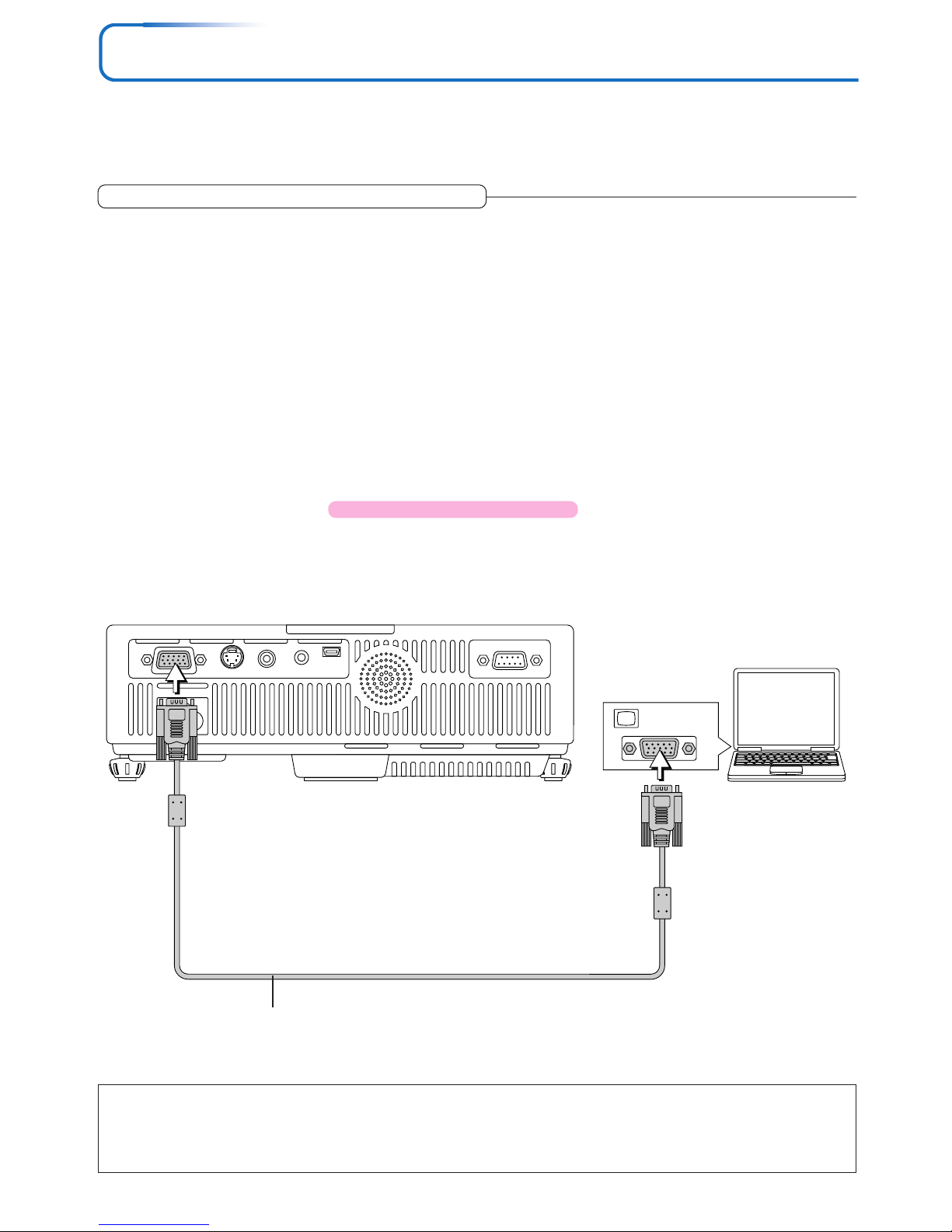
MONITOR OUT
Personal
computer
RGB signal cable (Supplied item)
Note:
* Before making connections, check the power of the projector and the equipment to be connected is switched off.
* When projection will be with a notebook computer connected, knowledge will be required for the cable connection and notebook computer
startup procedure as well as the operation that follows startup. Please consult the instruction manual of your notebook computer or the online help.
Connections with Personal Computer
Please check the following before making connections with the personal computer.
• A suitable resolution for the U5-512h is 800 ⳯ 600 dots (S-VGA) and the maximum displayable resolution is XGA (1024 ⳯ 768
dots).
• A suitable resolution for the U5-632h/U5-732h/U5-532h is 1024 ⳯ 768 dots (XGA) and the maximum displayable resolution is
S-XGA (1280 ⳯ 1024 dots).
Make changes to a displayable resolution at the personal computer side. Please check with “Table of Supported Frequency” on
Page E-71.
• The setting method for the personal computer will differ depending on the specific model. Please read the personal computer
instruction manual or the on-line help information, or contact the manufacturer of your personal computer.
Connect the projector’s RGB connector using the included RGB signal cable.
• When making connections with the RGB connector of the projector, please make the connection via the supplied RGB signal
cable.
• The projector has been set to “Auto” at the factory; however, if it does not project, please change the input setting to “RGB”
using the menu sequence of [Setup] → [Input Format] → [RGB].
See “Input Format” on Page E-56.
• If the USB cable is connected to the projector’s MOUSE connector, mouse operations can be performed on the computer from
the projector’s remote control unit. Applicable Projector: U5-632h/U5-732h
See “Performing Mouse Operations on the Computer with the Remote Control Unit” on Page E-35.
Page 18

E-18
Connecting Personal Computers and Video Equipment
To Output the External Output Signal of a Notebook Computer
When projection will be with a notebook computer connected, knowledge will be required for the cable connection and notebook
computer startup procedure as well as the operation that follows notebook startup. Please consult the instruction manual of your
notebook computer or the on-line help while performing the following procedure.
1
Check whether a signal is being sent from the notebook computer to the projector.
An indication appearing on the liquid crystal display of the notebook computer does not necessarily mean that an external
output signal is being output.
REFERENCE: When “Resolution” or “Frequency” is not displayed under “Info.” on the menu of the projector, this means that
the external output signal is not being output from the personal computer. See “Resolution/Frequency” on Page E-60.
2
Should a sign not be output from the notebook computer, please try the operation described below.
For an IBM PC/AT compatible computer, press the [Fn] key plus any one of the [F1] to [F10] keys. (See the table below.)
Note:
When the liquid crystal display of the notebook computer and the projector are displayed at the same time, the projected image might not be
correct even though the liquid crystal display shows a correct indication. Should this occur, stop the simultaneous display of the notebook
computer and try the mode with external output only. Try an operation such as that described in aforementioned Step 2 and try closing the
liquid crystal panel which might result in external output only.
Manufacturer Model Key
DELL All computers Fn + F8
EPSON All computers Fn + F8
FUJITSU All computers Fn + F10
iiyama All computers Fn + F3
IBM All computers Fn + F7
NEC All computers Fn + F3
Panasonic All computers Fn + F3
SHARP All computers Fn + F5
SONY All computers Fn + F7
SOTEC All computers Fn + F3–F5
TOSHIBA All computers Fn + F5
Victor All computers Fn + F10
Note: Table information is current to December 2003.
Page 19
E-19
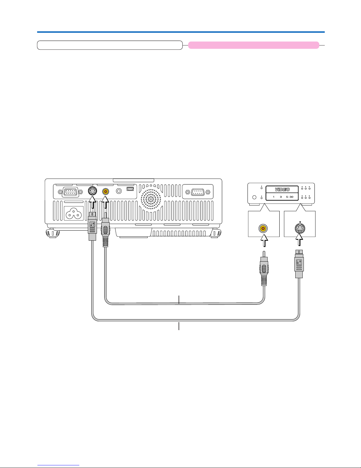
VIDEO
S-VIDEO
Connecting Personal Computers and Video Equipment
Connections with Composite Signals
Video Equipment with VIDEO Connectors
• The input setting of the VIDEO connector has been set to “Auto” at the factory; however, if the projector does not project, please
change the input setting to “Your Country’s Television Broadcast System” using the menu sequence of [Setup] → [Input Format]
→ [Video].
See “Input Format” on Page E-56.
Video Equipment with S-VIDEO Connectors
• Make the connection to the S-VIDEO connector of the projector using the supplied S-video cable.
• The input setting of the S-VIDEO connector has been set to “Auto” at the factory; however, if the projector does not project,
please change the input setting to “Your Country’s Television Broadcast System” using the menu sequence of [Setup] → [Input
format] → [S-Video].
See “Input Format” on Page E-56.
Video deck, DVD player, document
camera, etc.
Video cable (Supplied item)
S-Video cable (Suppled item)
Applicable Projector: U5-632h/U5-732h/U5-532h
Page 20
E-20
CrCbY
PrPbY
COMPONENT
COMPONENT
Connecting Personal Computers and Video Equipment
Connections with Component Signals
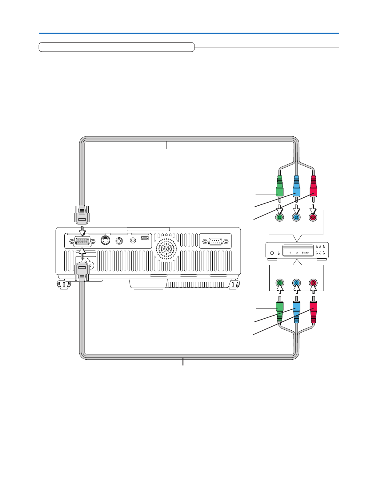
When the Video Equipment Has a YCbCr Connector or YPbPr Connector
• The projector has been set to “Auto” at the factory; however, if it does not project, please change the input setting to “Compo-
nent” using the menu sequence of [Setup] → [Input Format] → [RGB].
See “Input Format” on Page E-56.
• When projecting the YCbCr signal or YPbPr signal, if the color of the overall image strongly leans toward being greenish or
another color, change the setting under the menu of [Color] → [Color Space].
See “Color Space” on Page E-50.
Component cable (Available as an option)
Order code: 28-690
Component cable (Available as an option)
Order code: 28-690
Green
Blue
Red
Green
Blue
Red
Page 21

E-21
Connecting Personal Computers and Video Equipment
Connections with the AUDIO Jack
* Make the connection to the projector’s AUDIO jack using the supplied audio cable. When the audio jack of the equipment that
is to be connected is of the RCA phono type, make connection via the supplied audio conversion adapter.
* The built-in speaker of the projector provides monaural audio. To enjoy convincing audio reproduction, please connect the
audio output of the video equipment to your audio system.
* The built-in speaker outputs the audio of the equipment connected to the AUDIO jack.
R
L
AUDIO OUT
White
Red
Audio conversion adapter
(Supplied item)
Audio cable (Supplied item)
Audio cable (Supplied item)
Applicable Projector: U5-632h/U5-732h/U5-532h
Page 22
E-22
Connecting Personal Computers and Video Equipment
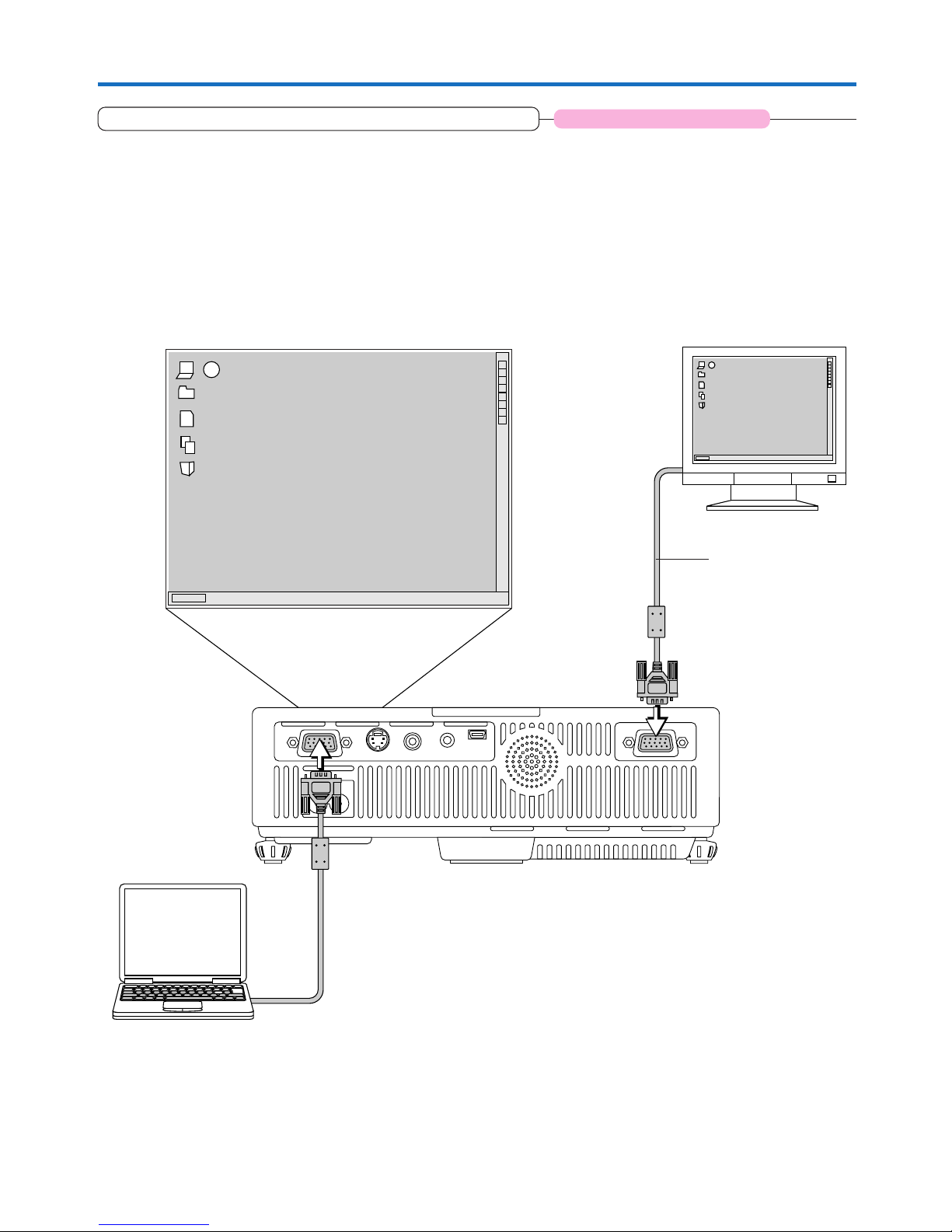
Connections with the RGB OUT Connector
• The image from the computer connected to the RGB connector is output.
• The image of the connector selected with the input selection function is output.
• If an input other than RGB is selected with the input selection function, the output does not switch.
• While controlling the personal computer in front of you, the same screen can be projected with the projector. This allows
personal computer control even from a position at which the projector image cannot be viewed.
RGB connector of
the monitor
(Mini D-Sub 15-pin)
Image projected to the screen
Applicable Projector: U5-512h
Page 23
E-23
Power Cable Connections and Switching the Power On/Off
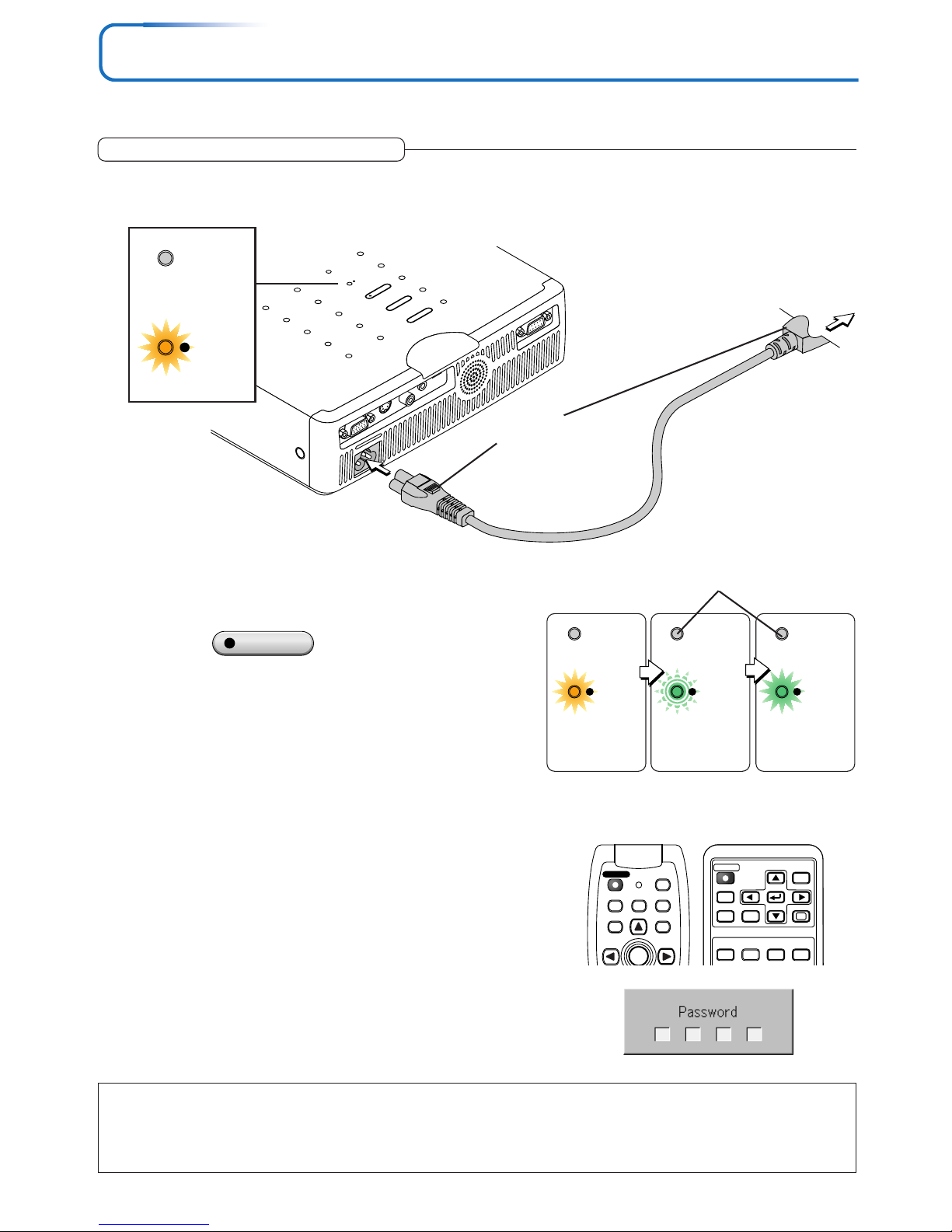
There is an order in which the power cable is connected and the power is switched on/off.
2
Switch on the projector power
Press the STANDBY button.
The first time the power is switched on after purchase, [Menu
Language Select] will be displayed. See Page E-24 for information about language selection.
• When the power is turned on, the STANDBY indicator starts
flashing green, then stops flashing after about 60 seconds. If
the STATUS indicator lights green at this time, the lamp mode
is set to “Eco”. See E-30 and 55 for instructions on selecting.
• If the power does not come on, see “When the STATUS Indicator is Lit or Flashing” on Page E-61.
If the “Password” input window is displayed: See E-38.
A password is set for this projector.
The projector cannot be used unless the correct password is input.
To turn off the power: See E-25.
The projector is now capable of regular projection.
3
Switch on the power of the connected equipment
Note:
• When the power plug will be unplugged from the power outlet, please place the projector near the power outlet so that it may be reached
easily.
• Press the STANDBY button after the STANDBY indicator is lit in amber.
• The included power cable is exclusively for use with the U5-632h/U5-732h/U5-532h/U5-512h. Never use it with other products.
STANDBY
STANDBY
STATUS
STANDBY
STATUS
STANDBY
STATUS
This indicator is also lit green in Eco-mode.
Flashing green
(Approximately 60
seconds)
Lit green
Power is on
Lit amber
(button on main unit)
RGB
STANDBY
VIDEO
FREEZE
MUTE
ECO AUTO
S
CANCEL QUICK
MENU
ENTER
Q
1234
LASER
AUTO
RGB
VIDEO
QUICKMENU
Q
STANDBY
Operating
S
TAN
D
B
Y
S
TA
TU
S
STANDBY
AUTO
SOURCE
RGB
S VIDEO
VIDEO
AUDIO
MOUSE
PC CONTROL
1
Connect the AC IN connector of the projector and the power outlet using the supplied power cable.
The STANDBY indicator will light in amber, and the unit will enter the standby mode.
Firmly plug in all the way.
To wall outlet
STANDBY
STATUS
Lit amber
Page 24
E-24
When [Menu Language Select] is Displayed Upon Switching On the Power
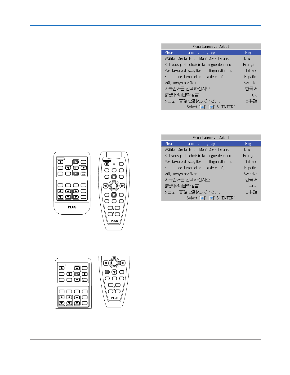
1
Press the SELECT (왖왔) buttons of the Remote control and align the deep blue cursor with [English].
Cursor
2
Press the ENTER button to set.
This will set the language and [Menu Language Select] will close.
This completes the selection of the display language.
Caution:
[Menu Language Select] will not appear the next time the power is switched on.
Should a change of language become necessary, see “Language” on Page E-57.
RGB
STANDBY
VIDEO
FREEZE
MUTE
ECO AUTO
ASPECT
TIMER
VOL KSTN ZOOM
CANCEL QUICK
MENU
ENTER
Q
1234
FREEZE
MUTE
LASER
AUTO
TIMER
VOL
ZOOM
RGB
VIDEO
R-CLICK/
CANCEL
QUICKMENU
ENTER
STANDBY
Q
12
34
RGB
STANDBY
VIDEO
FREEZE
MUTE
ECO AUTO
ASPECT
TIMER
VOL KSTN ZOOM
CANCEL QUICK
MENU
ENTER
Q
1234
FREEZE
MUTE
TIMER
VOL
ZOOM
R-CLICK/
CANCEL
ENTER
12
34
Power Cable Connections and Switching the Power On/Off
The first time the power is switched on after purchase, [Menu Language Select] will be displayed. Follow the procedure described below and select the display language of the projector.
If the image is blurred, turn the focus ring counterclockwise or clockwise to focus it. See Page E-27.
Page 25
E-25
Power Cable Connections and Switching the Power On/Off
Finishing
Warrning
Do not unplug the power cable while the STANDBY indicator is flashing amber. Doing so may shorten the life of the lamp
or damage the projector.
1
Switch off the power of the connected equipment
RGB
STANDBY
VIDEO
FREEZE
MUTE
ECO AUTO
S
CANCEL QUICK
MENU
ENTER
Q
1234
LASER
AUTO
RGB
VIDEO
QUICKMENU
Q
STANDBY
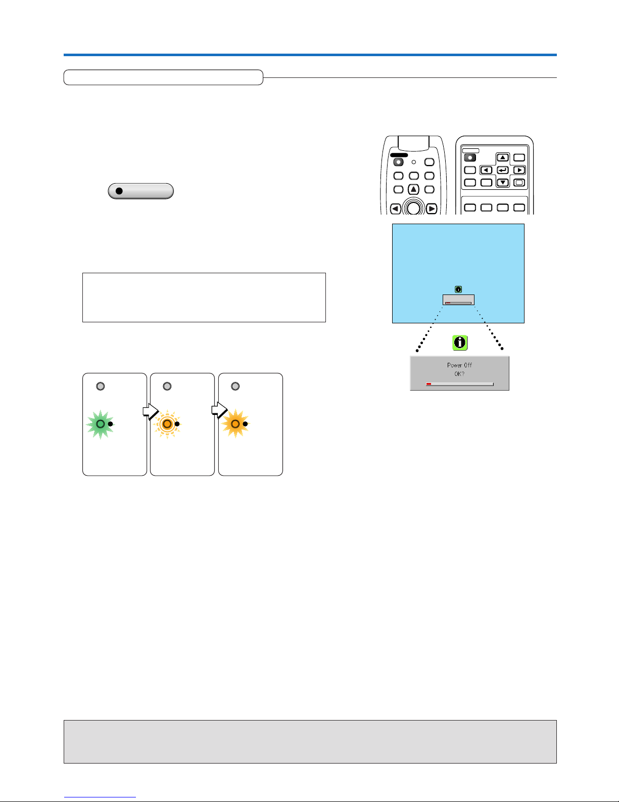
2
Switch off the power of the projector
Press the STANDBY button.
The [Power Off] display appears.
When the level gauge reaches maximum, the projection screen
will go off (in about 5 seconds) and the projector will enter the
power-off operation.
Note
* The operation can be cancelled by pressing a button other than
the STANDBY button.
* One more press of the STANDBY button will switch off the power.
The STANDBY indicator changes to flashing amber and lights a
steady amber after about 90 seconds (when the unit enters the
standby mode).
Flashing amber
(Approximately 90
seconds)
Lit amber
Standby mode
STANDBY
STATUS
STANDBY
STATUS
STANDBY
STATUS
Lit green
3
Unplug the power cable
Check that the STANDBY indicator is lit in amber and then unplug the power cable.
The STANDBY indicator will go off when the power cable is unplugged.
Power Off
OK
?
STANDBY
(button on main unit)
Page 26
E-26
Adjustment of the Projection Screen
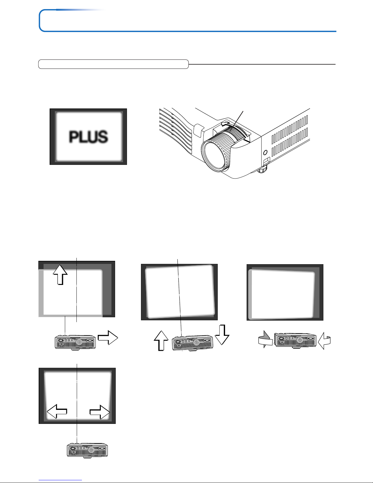
Switch on the power of the connected equipment and make the adjustments with the video signal being input to the
projector.
2
(2)
(1)
(3)
(4)
(5)
(3)
(4)
Adjust the projection image to the screen.
Check that the screen is set level and vertically.
(1) If the image is shifted to the left or right, move the main unit horizontally. (Align the center of the screen and the center of
the projector lens.)
(2) If the image is shifted vertically, move the image up or down with the adjuster. See “Making Adjustments with the Adjust-
ers” on Page E-27.
(3) If the image is slanted, adjust by turning the right or left adjuster. See “Making Adjustments with the Adjusters” on Page E-
27.
(4) A projection image such as that illustrated in the diagram is the result of the projector not being perpendicular to the
screen. Set the projector so that it is pointing straight toward the screen.
(5) If the image shows keystone distortion, adjust using remote control or menu operations. See “Keystone” on Page E-31, 53.
Turn the zoom ring to adjust the screen size of the projection image.
Adjust the image to match the desired screen size. When outside of the adjustment range, move the projector to the rear or
forward.
1
Zoom ring
Adjustment of the Projection Screen
Page 27
E-27
Adjustment of the Projection Screen
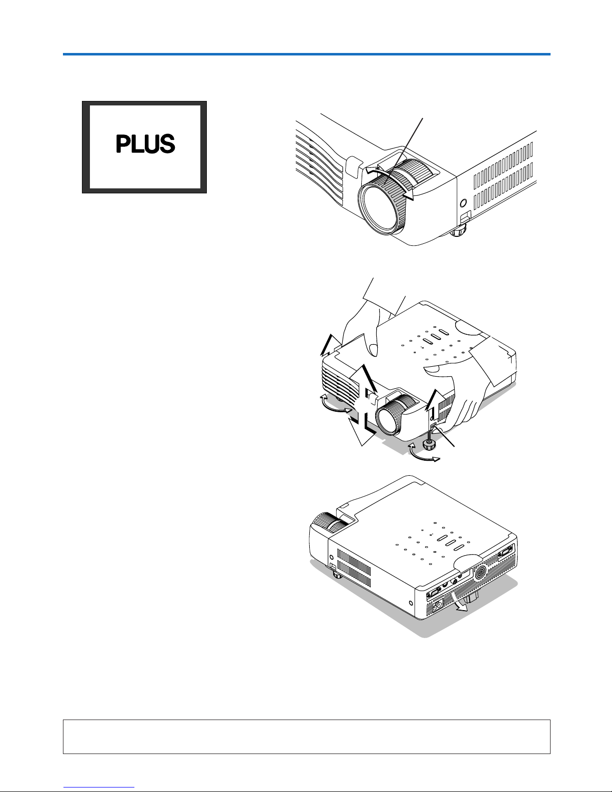
3
Turn the focus ring and adjust the focus of the screen
Focus ring
Note:
When the projector has a suspended or rear installation is used, the orientation of the projection will need to be changed.
Please see “Vertical Flip” on Page E-53.
S
T
A
N
D
B
Y
S
T
A
T
U
S
STANDBY
AUTO
SOURCE
R
G
B
S
V
I
D
E
O
V
I
D
E
O
A
U
D
I
O
M
O
U
S
E
P
C
C
O
N
T
R
O
L
Making Adjustments with the Adjusters
Raising the projection image
While viewing the projection image, (1) press and hold
the front adjuster buttons located at the left and right and,
(2) raise the projector to align the image with the screen,
then release your fingers.
Turn the left and right front adjusters for fine adjustment.
Adjust so that there is no shaking of the projector.
Lowering the projection image
Lower the front adjusters using the operation described
above.
To lower the projection screen further, raise the rear adjuster. Fine adjustments are made by turning the left and
right front adjusters. Make adjustments so that there is
no rattling.
(1)
STANDBY
STATUS
STANDBY
AUTO
SOURCE
(1)
(2)
Adjuster button
Page 28
E-28
General Operation
This section describes the use of direct operation with the main unit or remote control buttons.
For information about operation using the menu, see “Menu Operation Method” on Page E-40 and the various items on
Pages E-47 to E-60.
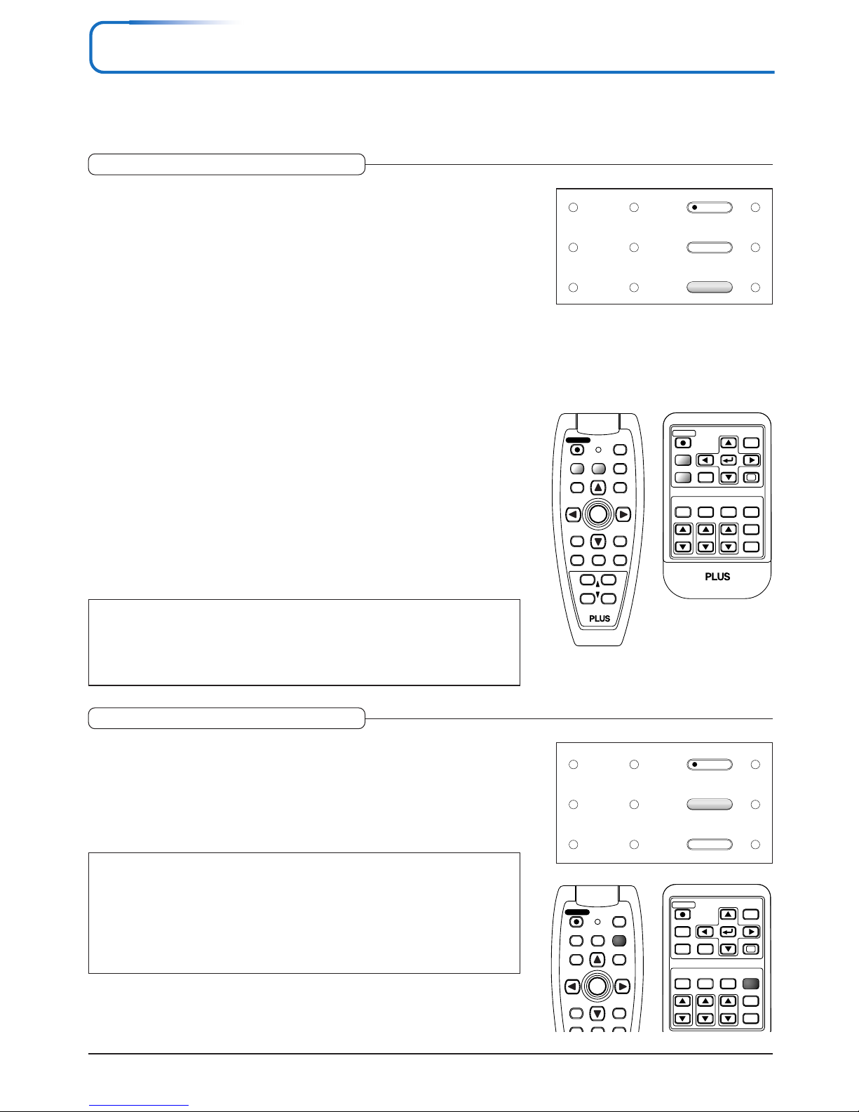
Input Selection
This operation selects the input signal to be projected.
Main unit operation: Press the SOURCE button.
(It will not function while the menu or the quick menu is displayed.)
When Auto Source is On
Whenever the SOURCE button is pressed, the projector automatically selects
another source that has the next input signal.
When Auto Source is Off
The input selection condition used last time will be set.
Each press of the button moves the selection one step in the sequence of RGB →
VIDEO → S-VIDEO. Note that the various input signals will become the signal
type set with [Input Format] See“Input Format” on page E-56.
Remote control operation: Press the desired input selection button.
RGB button ........ Switches the RGB input.
VIDEO button ..... The input switches between VIDEO and S-VIDEO each time the button is
pressed.
When Auto Source is On
When an input signal is not present at the selected source, the projector automatically selects the next source that has an input signal.
When Auto Source is Off
The projector switches to the selected source regardless of whether an input signal is present.
Note:
* When you do not operate source selection, the projector will assume the input selec-
tion condition that was previously used.
* See “Auto Source” on Page E-54 for information about the Auto Source on and off
conditions.
STANDBY
FREEZE
MUTE
ECO AUTO
ASPECT
TIMER
VOL KSTN ZOOM
CANCEL QUICK
MENU
ENTER
Q
1234
FREEZE
MUTE
LASER
AUTO
TIMER
VOL
ZOOM
R-CLICK/
CANCEL
QUICKMENU
ENTER
STANDBY
Q
12
34
RGB
VIDEO
RGB
VIDEO
STANDBY
AUTO
SOURCE
Automatic Adjustment
This function automatically adjusts the position shift, screen size, vertical stripes,
and color infidelity of the projected analog RGB input signal.
Normally automatic adjustment is performed at the time of signal selection.
Main unit operation/Remote control operation: Press the AUTO button.
(This will not function while the menu or the quick menu is displayed.)
A press of the AUTO button starts the automatic adjustment.
Note:
* If the display position is shifted, vertical lines appear on the picture, or the projection
is not good even after using automatic adjustment, please perform image adjustment
manually. See “Picture Adj. / Fine Picture / H Position / V Position” on Page E-47.
* When the image extends beyond the boundaries of the screen or is smaller than the
screen, set Aspect to “Auto”. See “Selection of Aspect Ratio” on Page E-29 and “As-
pect” on Page E-52.
RGB
STANDBY
VIDEO
FREEZE
MUTE
ECO
ASPECT
TIMER
VOL KSTN ZOOM
CANCEL QUICK
MENU
ENTER
Q
123
AUTO
4
FREEZE
MUTE
LASER
TIMER
RGB
VIDEO
R-CLICK/
CANCEL
QUICKMENU
ENTER
STANDBY
Q
AUTO
STANDBY
SOURCE
AUTO
Page 29
E-29
General Operation
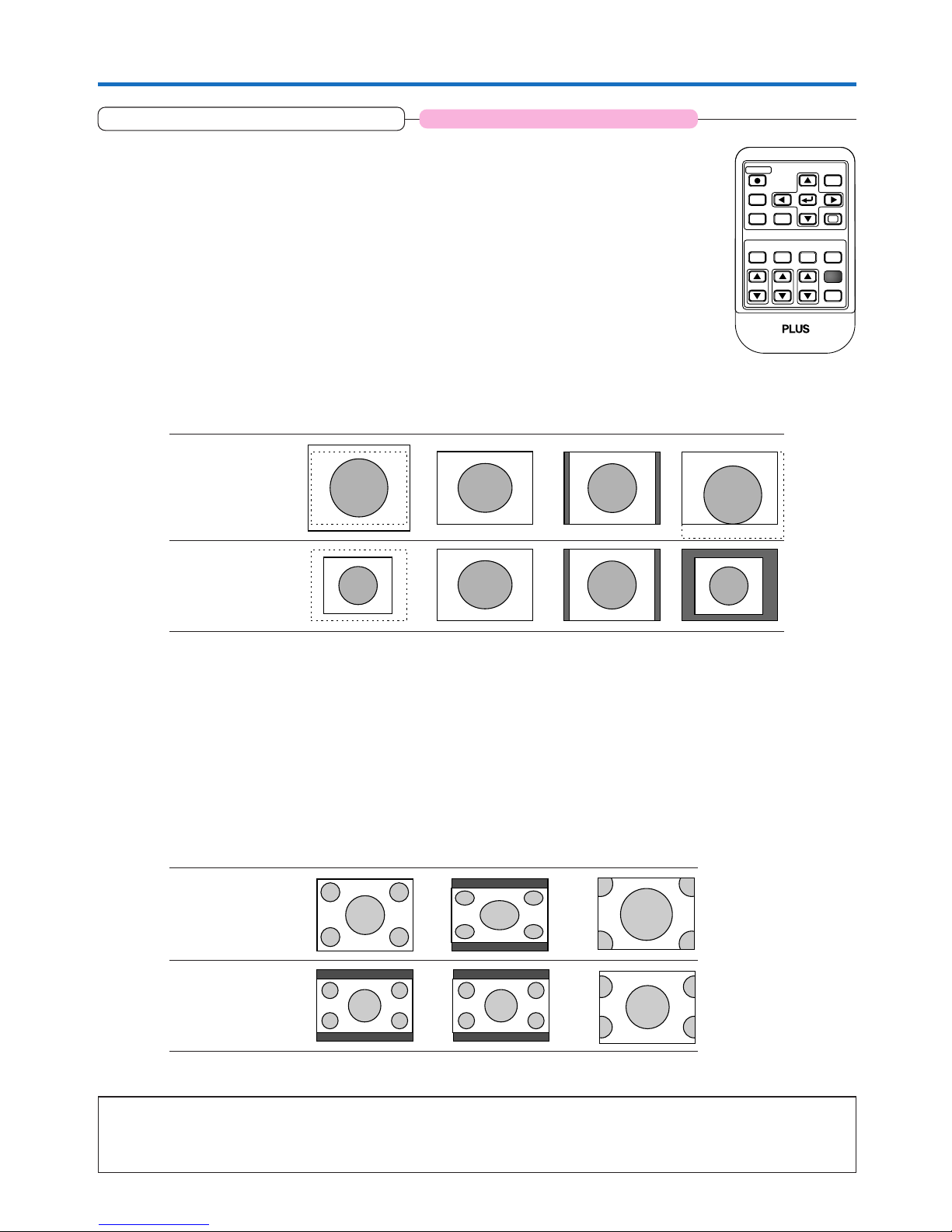
Selection of Aspect Ratio
Video Signals / Component Signals
Each press of the ASPECT button advances the selection one step in the sequence of Auto → Wide → Zoom, and then repeats.
Auto ............ While maintaining the aspect ratio, projects a full screen so that no portions extend beyond the boundaries of the screen. The top
and bottom of the 16:9 image becomes black.
Wide ........... Projects to fill the full width with the entire image at 16:9.
(This feature is used to project a squeezed image in a proper aspect ratio.)
Zoom .......... Projects only the 4:3 portion within 16:9 image to fill the screen.
(Portion that extend off screen is cut.)
Aspect ratio selection Auto Wide Zoom
4:3 screen
16:9 screen
Note:
When selection has been made for the “Real” setting of the personal computer signal (i.e., when the input signal and the projector display
resolution are high) and the “Zoom” setting of the video signal, pressing the SELECT (
왖왔왗왘
) buttons on the remote control will permit
movement of the display position. Note that there will not be any movement when the menu or the quick menu is displayed.
Applicable Projector: U5-532h/U5-512h
This function selects horizontal and vertical picture proportions of the input
signal.
Press the ASPECT button while viewing the projected image and select the
aspect ratio.
Personal Computer Signal
Each press of the ASPECT button advances the selection one step in the sequence of Auto → Direct → Real, and then repeats.
Auto ............ Automatically enlarges or reduces the image to project a full screen in a ratio
of 4:3
Direct .......... Maintains the aspect ratio and projects a picture of the maximum displayable
size
Real ............ Projects the input signal without pixel conversion.
RGB
STANDBY
VIDEO
FREEZE
MUTE
ECO AUTO
TIMER
VOL KSTN ZOOM
CANCEL QUICK
MENU
ENTER
Q
1234
ASPECT
For the U5-632h/
U5-732h projector,
these operations
are possible using
the menus. The
operations are the
same. See E-52
[Aspect].
Input Signal Auto Direct Real
The setting is higher
than the display resolution of the projector.
The setting is lower
than the display resolution of the projector.
Page 30
E-30
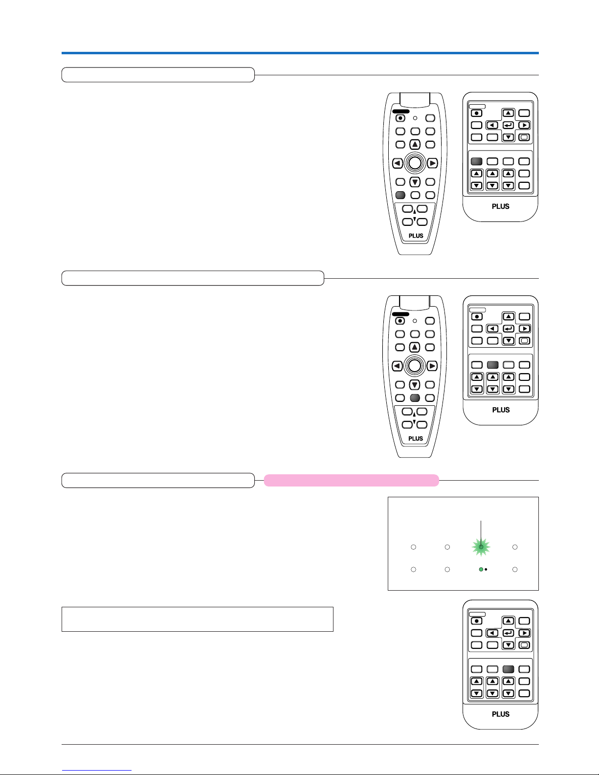
Freezing a Moving Picture
General Operation
This function is used to stop and view a moving picture. Note that the input
image continues to advance even though the picture there is a still picture
condition.
A press of the FREEZE button changes the screen to a still picture. A
further press returns the screen to a moving picture.
RGB
STANDBY
VIDEO
MUTE
ECO AUTO
ASPECT
TIMER
VOL KSTN ZOOM
CANCEL QUICK
MENU
ENTER
Q
234
FREEZE
1
MUTE
LASER
AUTO
TIMER
VOL
ZOOM
RGB
VIDEO
R-CLICK/
CANCEL
QUICKMENU
ENTER
STANDBY
Q
12
34
FREEZE
Lamp Mode
Applicable Projector: U5-532h/U5-512h
STANDBY
STATUS
STATUS indicator
RGB
STANDBY
VIDEO
FREEZE
MUTE
AUTO
ASPECT
TIMER
VOL KSTN ZOOM
CANCEL QUICK
MENU
ENTER
Q
12 4
ECO
3
For the U5-632h/
U5-732h projector,
these operations
are possible using
the menus. The
operations are the
same. See E-55
[Lamp Mode].
Use this if the picture is projected on a small screen and the picture
is too bright or when projecting images in dark rooms.
Pressing the ECO button will set the lamp mode.
Eco (STATUS indicator is lit green)
Lamp brightness is set to 80% and the lamp life is extended.
Normal (STATUS indicator is off)
Lamp brightness is set to 100% and the screen is bright.
Note:
Frequent switching this mode can degrade the lamp.
Cancelling Video and Audio Temporarily
This function is used to cancel the video and audio at the same time.
A press of the MUTE button will blank the picture and the sound, and
the screen will take on the background color that has been set.
Another press will cause a return to the original conditions.
RGB
STANDBY
VIDEO
FREEZE
ECO AUTO
ASPECT
TIMER
VOL KSTN ZOOM
CANCEL QUICK
MENU
ENTER
Q
134
MUTE
2
FREEZE
LASER
AUTO
TIMER
VOL
ZOOM
RGB
VIDEO
R-CLICK/
CANCEL
QUICKMENU
ENTER
STANDBY
Q
12
34
MUTE
Page 31
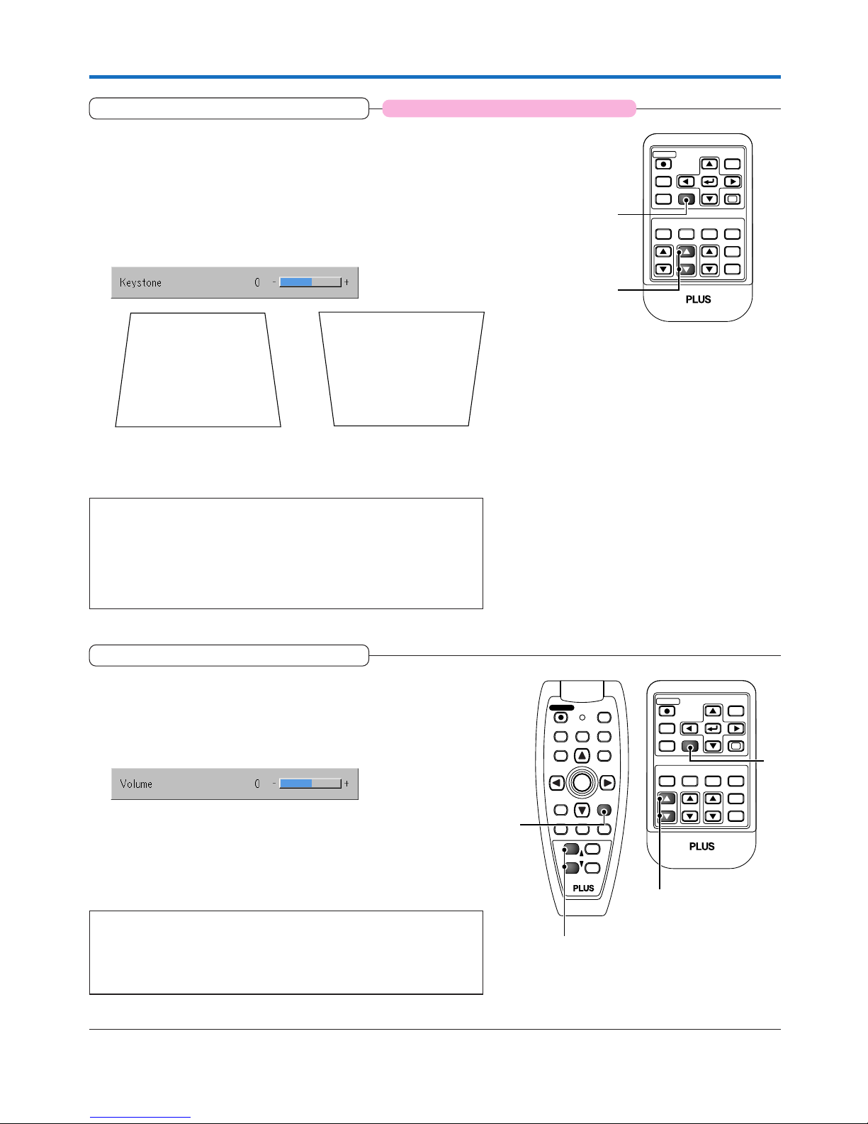
E-31
Keystone
General Operation
Use this to adjust for trapezoidal (keystone) distortion of the projected image.
Adjustment Method
(1) Press the 왖 or 왔 KSTN button to make the left and right sides
parallel.
The keystone adjustment display appears when one of the buttons is
pressed.
RGB
STANDBY
VIDEO
FREEZE
MUTE
ECO AUTO
ASPECT
TIMER
VOL ZOOM
QUICK
MENU
ENTER
Q
1234
KSTN
CANCEL
(1)
(2)
For the U5-632h/U5-732h
projector, these operations are possible using
the menu. The operations
are the same. See E-39,
53.
(2) Press the CANCEL button to immediately close the display.
The display will close when there has not been an operation in about
10 seconds.
Note:
* Keystone adjustment values can be saved. See “Keystone Save” on Page
E-53.
* Screen examples have been drawn in an exaggerated style for the purpose
of description.
* Please note that depending on the projected picture and the projection con-
ditions, it may not be possible to eliminate keystone distortion completely.
Press the 왔 button. Press the 왖 button.
Adjustment of the Volume
This function adjusts the volume of the built-in speaker.
(1) Press the 왖 or 왔 VOL button to adjust the volume.
The volume adjustment display appears when one of the buttons is
pressed.
The 왖 button increases the volume and the 왔 button decreases the
volume.
(2) Press the CANCEL button to immediately close the display.
The display will close when there has not been an operation in about
10 seconds.
Note:
* Adjustment of the volume will not produce any sound unless an image is
being projected.
* Please make connections to the AUDIO connectors of the projector with the
supplied audio cable.
RGB
STANDBY
VIDEO
FREEZE
MUTE
ECO AUTO
ASPECT
TIMER
KSTN ZOOM
QUICK
MENU
ENTER
Q
1234
VOL
CANCEL
FREEZE
MUTE
LASER
AUTO
TIMER
ZOOM
RGB
VIDEO
R-CLICK/
CANCEL
QUICKMENU
ENTER
STANDBY
Q
2
4
VOL
1
3
(1)
(2)
(1)
(2)
Applicable Projector: U5-532h/U5-512h
Page 32
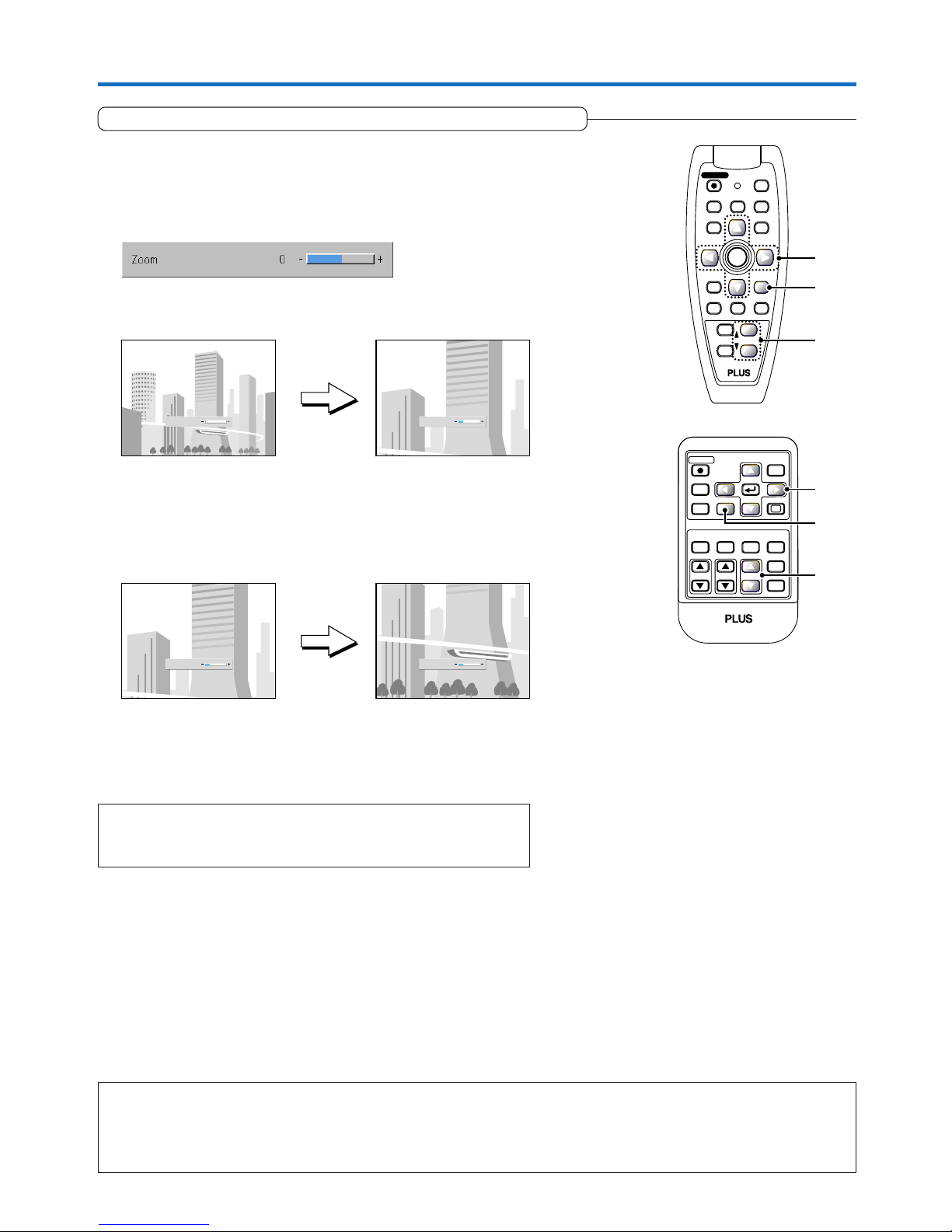
E-32
General Operation
Enlargement of the Image and Video Movement
Note:
* Zoom and image movement functions are cancelled when the input is switched.
* The greater the zoom enlargement, the less distinct the image will appear. The reason for this is that the dots are being digitally corrected
so that they are not conspicuous.
* Movement of the screen will not be possible when the menu screen is being displayed.
This function digitally enlarges the personal computer image and video
image.
(1) Press the ZOOM button to enlarge the image.
The zoom display appears when the ZOOM button is pressed.
Each press of the 왖 button enlarges the image and each press of the
왔 button makes the image smaller (returning it to 1:1).
The image can also be moved in the following circumstances.
• When “Aspect” is set to “Real” by the signal of the personal computer, and the input resolution is higher than the display
resolution of the projector.
• When “Aspect” is set to “Zoom” by the video signal.
(3) Press the CANCEL button to immediately close the display.
The display will close when there has not been an operation in about
10 seconds.
(2) Pressing the SELECT (왖왔왗왘) buttons on the remote control at
the time of the zoom operation will cause the display position to
move.
(There will not be any movement when zoom is at 0.)
(3)
(1)
(2)
(3)
(1)
(2)
RGB
STANDBY
VIDEO
FREEZE
MUTE
ECO AUTO
ASPECT
TIMER
VOL KSTN
CANCEL QUICK
MENU
ENTER
Q
1234
ZOOM
FREEZE
MUTE
LASER
AUTO
TIMER
VOL
RGB
VIDEO
R-CLICK/
CANCEL
QUICKMENU
ENTER
STANDBY
Q
1
3
ZOOM
2
4
(Approximately 2 times enlargement) (Movement)
Zoom
21
Zoom
21
(No enlargement) (Approximately 2 times enlargement)
Zoom
0
Zoom
21
Note:
After magnifying the image, be sure to use the ZOOM button to bring the gauge
value back to “0”.
Page 33
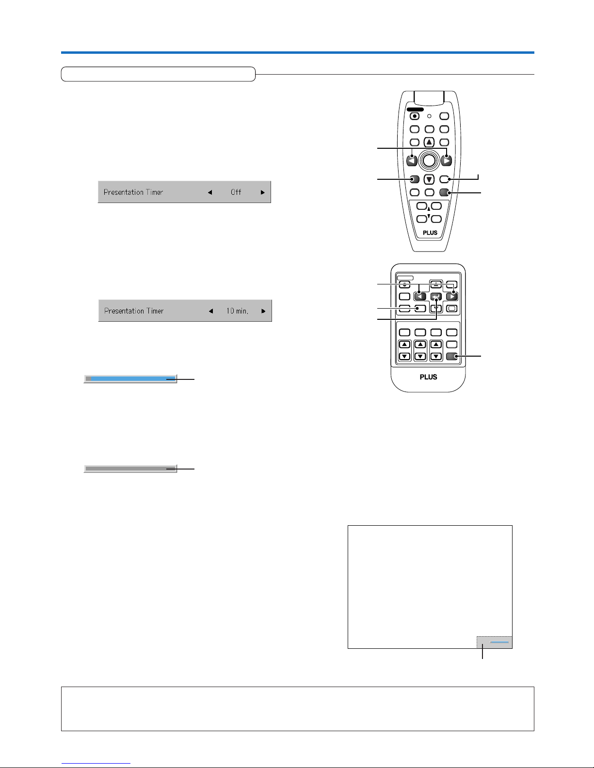
E-33
General Operation
Using the Presentation Timer
Note:
* The timer display will be closed while the menu or the quick menu is displayed, and while a message is displayed; however, the timer will
still be operating at such times. Also, the timer will not be displayed unless a signal is being input.
* While the presentation timer is being displayed, screen movement will not be possible in the zoom mode.
Movable Range of the Timer Display
[Timer settings display]
The presentation is given while checking the timer displayed
on the screen.
The gauge display allows the remaining time to be known at
a glance.
(1) Press the TIMER button to show the settings display.
The display will close when an operation has not been made
for about 10 seconds.
Press the CANCEL button to close the display immediately.
(2) Use the 왗 and 왘 SELECT buttons to set the time.
The setting contents are “Off” and from 10 to 60 minutes (in
10-minute intervals)
Settings can also be made with the SELECT (왗왘) buttons.
• Press the ENTER button to restart the timer. The timer will
start with the same time setting.
• Press the CANCEL button to close the timer display. The
timer setting will return to “Off”.
Moving the Position of the Timer Display
The SELECT (왖왔왗왘) buttons on the remote control permit movement within the movable range of the timer display.
RGB
STANDBY
VIDEO
FREEZE
MUTE
ECO AUTO
ASPECT
VOL KSTN ZOOM
CANCEL QUICK
MENU
Q
1234
FREEZE
MUTE
LASER
AUTO
VOL
ZOOM
RGB
VIDEO
R-CLICK/
CANCEL
QUICKMENU
STANDBY
Q
12
34
TIMER
ENTER
TIMER
ENTER
(1)
(2)
(3)
(1)
(2)
(3)
CANCEL button
CANCEL button
When the remaining time is
“0” (Gray)
(3) Press the ENTER button and start the timer.
• The display of the timer setting will close, the display of the
timer will appear and simultaneously the timer will start.
The blue gauge indicates the remaining time. When the
gauge disappears,the time is up.
The gauge continues to be displayed when the timer is
stopped.
[Timer Display]
Gauge (Blue)
Page 34
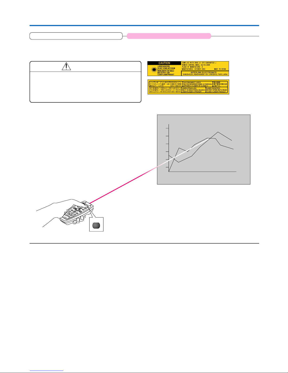
E-34
General Operation
Using the Laser Pointer
The remote control unit’s laser pointer can be used to point to the section currently being explained, making presenta-
tions more effective.
CAUTION
Do not look at the laser pointer’s light source.
Be sure to heed the following. Pointing the laser beam at
the eyes could lead to reduced vision or vision impairment.
• Never look at the laser pointer’s light source.
• Do not point the laser beam at people.
• Do not let children use the laser pointer.
This label is located on the side of the remote control.
Operation
The red laser beam is emitted from the tip of the remote control
unit while the LASER button is pressed in. Point the remote control unit’s transmitter in the direction you want to indicate.
The laser beam turns off when you release your finger from the
LASER button.
F
R
E
E
Z
E
M
U
T
E
L
A
S
E
R
A
U
T
O
T
IM
E
R
V
O
L
Z
O
O
M
R
G
B
V
ID
E
O
R-CLICK/
CANCEL
Q
U
IC
K
M
E
N
U
E
N
T
E
R
S
T
A
N
D
B
Y
Q
12
34
LASER
Applicable Projector: U5-632h/U5-732h
Page 35
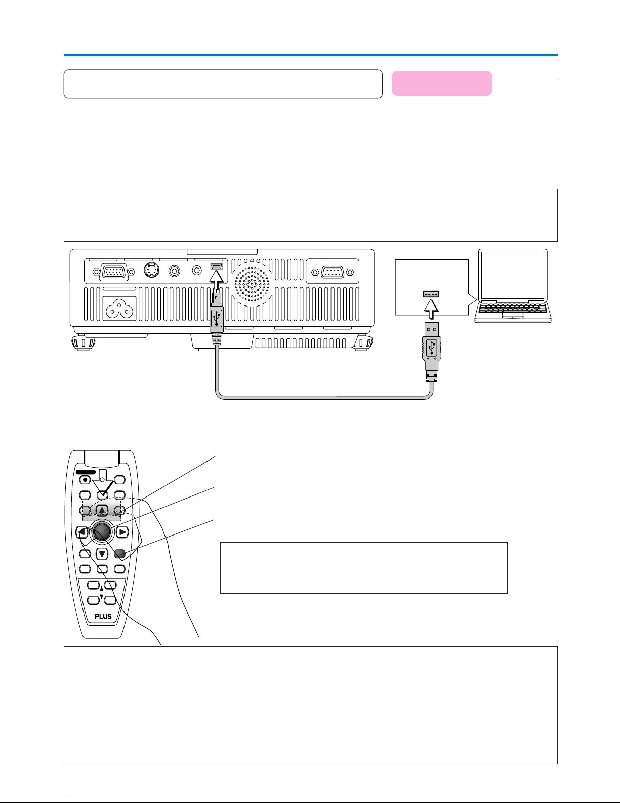
E-35
General Operation
Performing Mouse Operations on the Computer
with the Remote Control Unit
Functions of the mouse function buttons
When operating, point the remote control unit’s transmitter towards the remote control sensor on the projector.
Note:
Connections with USB Cables
* For PC/AT compatible computers, this function cannot be used with operating systems other than Windows 98SE, Me, 2000 and XP. For
Macintosh computers, this function cannot be used with operating systems other than OS 9 and later.
* When the cable is disconnected and then reconnected to the USB port of the personal computer or the MOUSE connector of the projector,
allow at least 5 seconds before reconnecting. Do not repeatedly disconnect and reconnect the cable in a momentary fashion. The personal
computer may not be able to correctly identify the projector as a result.
* The supplied USB cable is a dedicated cable for this projector. There is no guaranty that it will work in connections with other USB
equipment.
* This function may not work with some computers.
FREEZE
MUTE
LASER
AUTO
TIMER
VOL
ZOOM
RGB
VIDEO
QUICKMENU
ENTER
STANDBY
Q
12
34
R-CLICK/
CANCEL
L-CLICK button (on back)
Press this to perform the left-click operation.
JOG buttons
These move the computer’s pointer in the corresponding direction.
R-CLICK button
Press this to perform the right-click operation.
INFORMATION
The R-CLICK/CANCEL button is used for both the projector and mouse function. When the R-CLICK/CANCEL button is pressed while a menu is open, the
menu is closed.
USB cable (mini B to A type) (Supplied item)
When a computer and the projector are connected, mouse operations can be performed on the computer using the
projector’s remote control unit. When projecting images from the computer, the projector can be operated and mouse
operations on the computer performed with the same remote control unit, making for efficient presentations.
Connecting the computer and projector
Use the USB cable included with the projector to connect the computer’s USB (type A) connector to the projector’s MOUSE
connector.
Note:
* Be sure to plug the cable in securely.
* Depending on the type of connection, the computer’s operating system, etc., it may be necessary to change settings or restart the com-
puter after making the connections.
USB connector
Applicable Projector:
U5-632h/U5-732h
Page 36
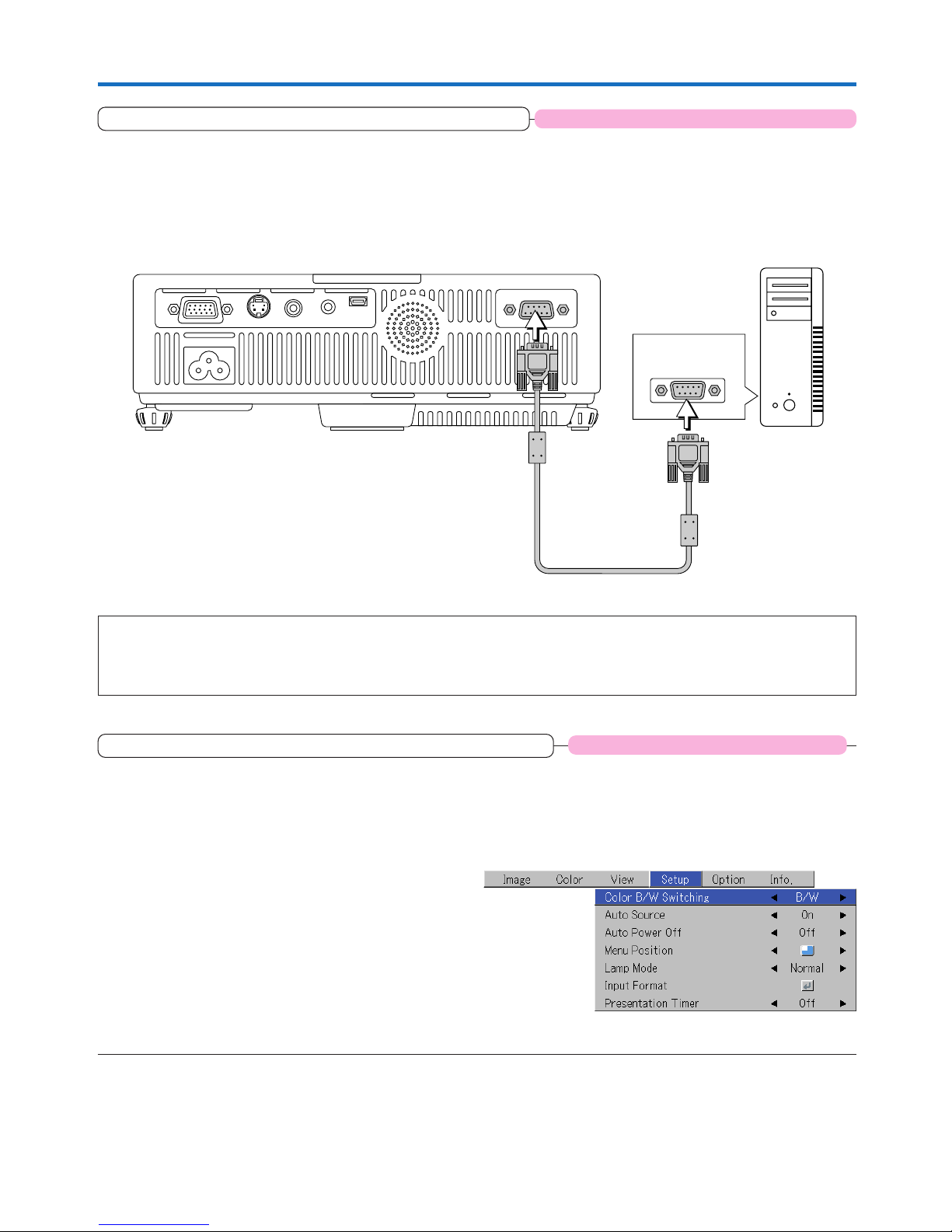
E-36
General Operation
Controlling the Projector from a Computer
Use the control connector if the projector cannot be operated with the remote control unit, for example when it is
suspended from the ceiling.
Connecting the computer and projector
Use a commercially available serial cable (D-Sub 9-pin, straight) to connect the computer’s RS-232C connector to the projector’s
control connector (PC CONTROL).
Serial cable (D-Sub 9-pin, straight) (commercially available)
RS-232C
connector
Note:
* This function may not work with some computers.
* Specialized knowledge is required to use the control connector. Consult a specialist, such as the person suspending the projector from the
ceiling.
Use as a High-Brightness Monochrome Projector
Data comprising a lot of black-and-white content such as documents and spreadsheets can be projected as a
highbrightness black-and-white image. While being projected, the image can be switched between black-and-white and
color.
Switching between color and black-and-white is done using the menus. For instructions on operating the menus, see “Menu
Operation Method” on E-40.
Select “Color B/W Switching” in the “Setup” menu, then
press one of the 왗 or 왘 SELECT buttons on the remote
control unit to select “B/W”.
When selected, the image switches to a high brightness blackand-white image.
Select “Color” to switch back to a color image.
Press the CANCEL button on the remote control unit to close
the menu display.
Applicable Projector: U5-632h/U5-532h
Applicable Projector: U5-632h/U5-732h/U5-532h
Page 37
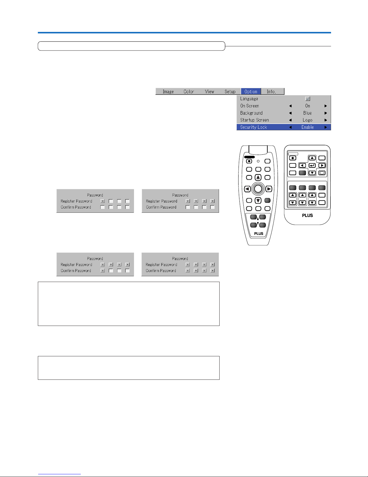
E-37
General Operation
Protecting the Projector with the Security Lock
A password can be registered and the security lock set in order to protect the projector from unauthorized use.
Registering the password
The password is registered using the menus. For instructions on operating the menus, see “Menu Operations” on E-40.
(1) Select “Security Lock” in the “Option” menu and set it to “Enable”.
The menu closes and the password registration display appears.
RGB
STANDBY
VIDEO
ASPECT
TIMER
VOL KSTN ZOOM
QUICK
MENU
ENTER
Q
FREEZE
MUTE
ECO AUTO
CANCEL
1234
FREEZE
MUTE
LASER
AUTO
TIMER
RGB
VIDEO
QUICKMENU
ENTER
STANDBY
Q
VOL
ZOOM
R-CLICK/
CANCEL
12
34
This completes password registration.
The “Password” input display appears the next time the power is turned
on.
(2) Use the number buttons (1 to 4) to register the password.
Be sure to input a 4-digit number.
Example: Registering the password “2441”
(1) Press number button “2”. An “*” (asterisk) appears at the first place.
Next press number buttons “4”, “4” and “1” in that order. Asterisks appear
in all four places.
(2) Input the password again. An “*” appears when the input number
matches. If there is a mistake, the asterisks turn off. Start over from step
(1) above.
If the password matches, the password registration display closes.
Note:
To cancel the number you have input, press the CANCEL button.
The asterisks disappear and the display returns to the input standby mode at the first
place.
To cancel the password registration mode, press the CANCEL button again. The “Pass-
word” display turns off.
Note:
The numbers you have input are not displayed. Be sure to write down the password
and store it in a safe place.
Page 38
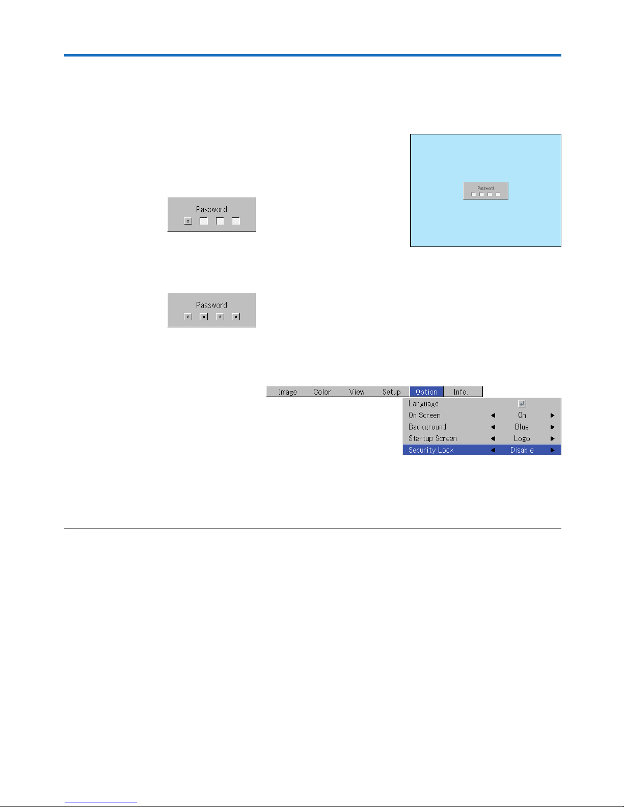
E-38
General Operation
If the password input display appears when the power is turned on
When a password has been registered, the “Password” input window appears on the projected image when the power is turned
on. The projector continues projecting this image until the correct password is input. At this time, only the STANDBY button (power
off) works. Use the procedure described below to input the registered password. For instructions on registering the password, see
E-37.
Input the password using the number buttons (1 to 4).
Be sure to input the registered 4-digit number.
Example: To input the password “2441”
Press number button “2”. An “*” (asterisk) appears at the first place.
Next press number buttons “4”, “4” and “1” in that order. Asterisks appear in all
four places.
If the password matches, the window turns off and the projector can be used
normally.
[Password input window]
Canceling the password/Changing the password
The password is canceled and changed using the menus. For instructions on operating the menus, see “Menu Operations” on
E-40.
Canceling the password
Select “Security Lock” in the “Option” menu and set it to “Disable”.
This clears the password and disables the security lock.
The password input display no longer appears when the power is turned on.
Changing the password
After setting “Security Lock” to “Disable” as described above, set it back to “En-
able”. The menu closes and the password registration display appears.
Register the new password. See “Registering the password” on E-37.
Page 39
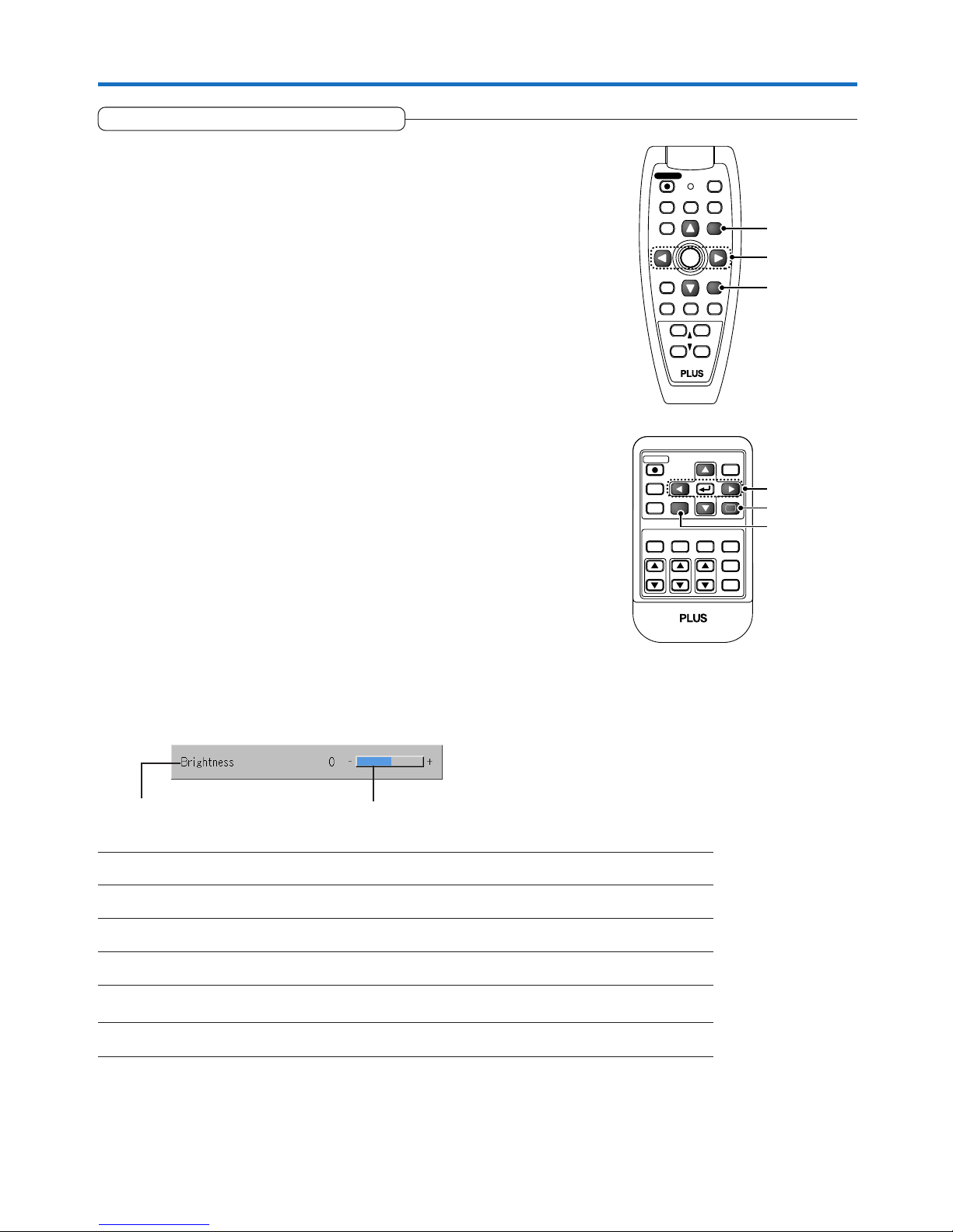
E-39
General Operation
Using the Quick Menu
RGB
STANDBY
VIDEO
FREEZE
MUTE
ECO AUTO
ASPECT
TIMER
VOL KSTN ZOOM
CANCEL
MENU
ENTER
1234
QUICK
Q
FREEZE
MUTE
LASER
AUTO
TIMER
VOL
ZOOM
RGB
VIDEO
R-CLICK/
CANCEL
MENU
ENTER
STANDBY
12
34
R-CLICK/
CANCEL
QUICK
Q
(1)
(2)
(3)
(2)
(1)
(3)
This function permits frequently used adjustments to be performed
quickly.
Note that the Quick Menu will not be displayed unless the signal of the connected equipment is input. Please select the input that you wish to adjust.
(1) A press of the QUICK MENU button brings up the quick adjustment
display.
Further presses cause the adjustment display to change in sequence.
The adjustment display can be selected with use of either the SELECT 왖 or
왔 button.
(2) Press the cursor 왗 or 왘 button to make the adjustment.
(3) To close the display immediately, press the CANCEL button.
In the absence of operations for a period of about 10 seconds, the display
will close automatically.
Brightness Adjusts the brightness of the image. See page E-47.
Contrast Adjusts the contrast of the image. See page E-47.
Keystone Corrects (vertical) keystone distortion of the screen. See page E-31.
Volume This function adjusts the volume of the built-in speaker. See page E-31.
Presentation timer Sets the time of the presentation timer. See page E-33.
Quick Color Adj. Select the preset color mode. See page E-49
Content of Adjustments and Settings
Example: Brightness adjustment display
Display Item Adjustment/Setting
Page 40
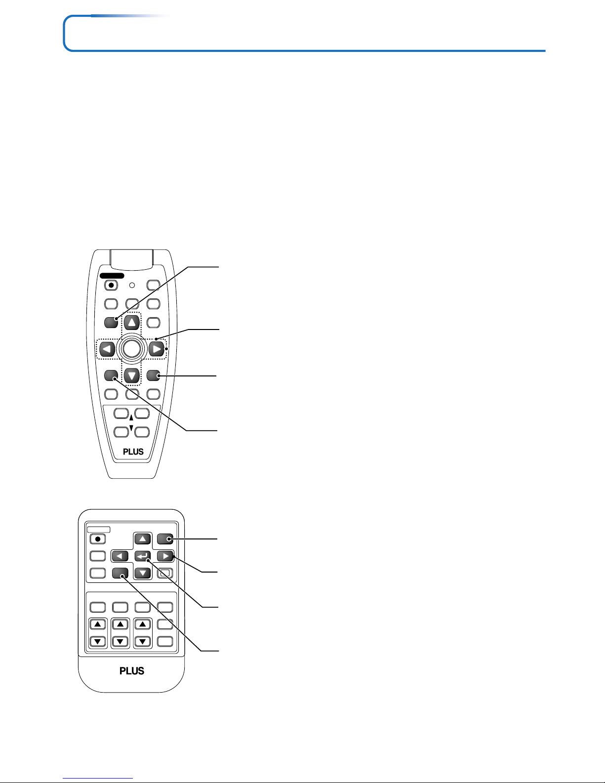
E-40
RGB
STANDBY
VIDEO
FREEZE
MUTE
ECO AUTO
ASPECT
TIMER
VOL KSTN ZOOM
QUICK
MENU
Q
1234
CANCEL
ENTER
FREEZE
MUTE
LASER
AUTO
TIMER
VOL
ZOOM
RGB
VIDEO
QUICK
STANDBY
Q
12
34
R-CLICK/
CANCEL
MENU
ENTER
Menu Operation Method
• This section describes only the menu operation method. Please see this item should you need information while
performing menu operations.
• For information about a menu function, adjustment, or setting, please see one of the pages containing such descriptions.
• Adjustments and settings are made by projecting an image and adjusting to an optimum condition.
• The remote control should be pointed toward the remote control sensor of the projector and operated.
• To return the various items that have been changed via the menu to their standard values (i.e., default values at time
of shipping from the factory), see “Factory Default” on Page E-59. (Some items will not return to their initial values.)
• The adjustment/setting items and contents will differ depending on the input selection and the adjustment/setting
items that can be used with the input signal are displayed on the menu.
MENU button
Used for menu display and menu closure.
SELECT (왖왔왗왘) buttons
Used in the selection of menu names and item names as
well as in setting and adjusting the item contents.
CANCEL button
Used to return to menu name selection as well as to close
the menu (and the sub menu display).
ENTER button
Used to set the verification display.
Names and functions of remote control unit buttons used for menu operations
MENU button
Used for menu display and menu closure.
SELECT (왖왔왗왘) buttons
Used in the selection of menu names and item names as
well as in setting and adjusting the item contents.
CANCEL button
Used to return to menu name selection as well as to close
the menu (and the sub menu display).
ENTER button
Used to set the verification display.
Page 41
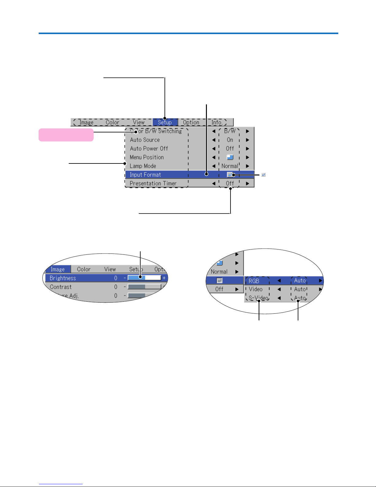
E-41
Menu Operation Method
Menu Screen Names and Functions
Menu Name
This is the title of the menu.
There is a change to the title screen
when the menu is selected.
The cursor moves to the selected
menu name.
Cursor (Deep Blue)
This permits setting/adjustment of the item
located at the cursor position.
Item Name
This is the name of
the adjustment or
setting.
Icon: Pressing the ENTER
button displays the sub menu
or setting contents.
Settings ContentsItem Name
Sub menu
Adjustment Bar
Adjustment Bar and Settings Contents
Adjustment Bar: The increases and decreases in bar length
express the adjustment condition.
Setting Contents: Displays the contents that have been set.
Applicable Projector:
U5-632h/U5-532h
Not selectable for other models.
Page 42
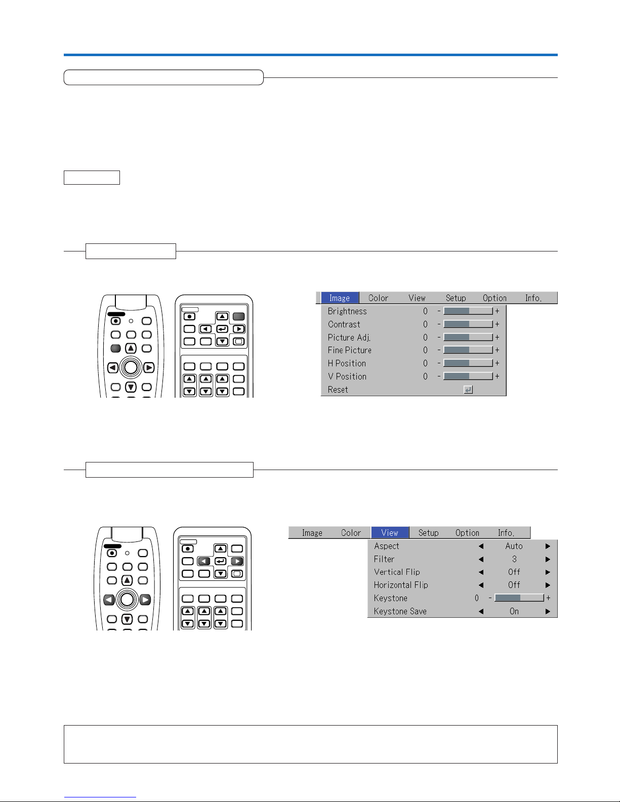
E-42
Menu Operation Method
Performing Menu Operations
• Only “Setup”, “Options” and “Info.” can be selected when no signal is being input.
• The menu display will close if, after pressing a button, the next button operation is not made within 30 seconds.
• The adjustment and the setting values are stored even when the power is switched off or the plug is disconnected
from the power outlet.
(Note that some items are not stored.)
Preparation Switch on the power of the connected equipment, start the play operation or another operation, and input
the signal to the projector.
Select the input that you wish to adjust.
The menu display of the description diagram depicts an example in which the “Keystone” item name is selected.
1
Press the MENU button to display the menu
Menu Display
The menu name that existed when the menu was closed previously will be displayed.
Note:
Please check that the cursor of the item name has disappeared at the time of menu name selection.
Press the CANCEL button to make the cursor disappear.
RGB
STANDBY
VIDEO
FREEZE
MUTE
ECO AUTO
ASPECT
TIMER
VOL KSTN ZOOM
CANCEL QUICK
ENTER
Q
1234
MENU
FREEZE
MUTE
LASER
AUTO
TIMER
RGB
VIDEO
R-CLICK/
CANCEL
QUICK
ENTER
STANDBY
Q
MENU
2
Press the SELECT (왗왘) button to select the menu name
Selection of the Menu Name
Each press of the SELECT 왘 button advances the selection one step in the sequence of “Color” → “View” → “Setup” →
“Option” → “Info.” → “Image”. Each press of the SELECT 왗 button causes a return of one step.
The cursor moves to the selected menu name.
RGB
STANDBY
VIDEO
FREEZE
MUTE
ECO AUTO
ASPECT
TIMER
VOL KSTN ZOOM
CANCEL QUICK
MENU
ENTER
Q
1234
FREEZE
MUTE
LASER
AUTO
TIMER
RGB
VIDEO
R-CLICK/
CANCEL
QUICKMENU
ENTER
STANDBY
Q
Page 43
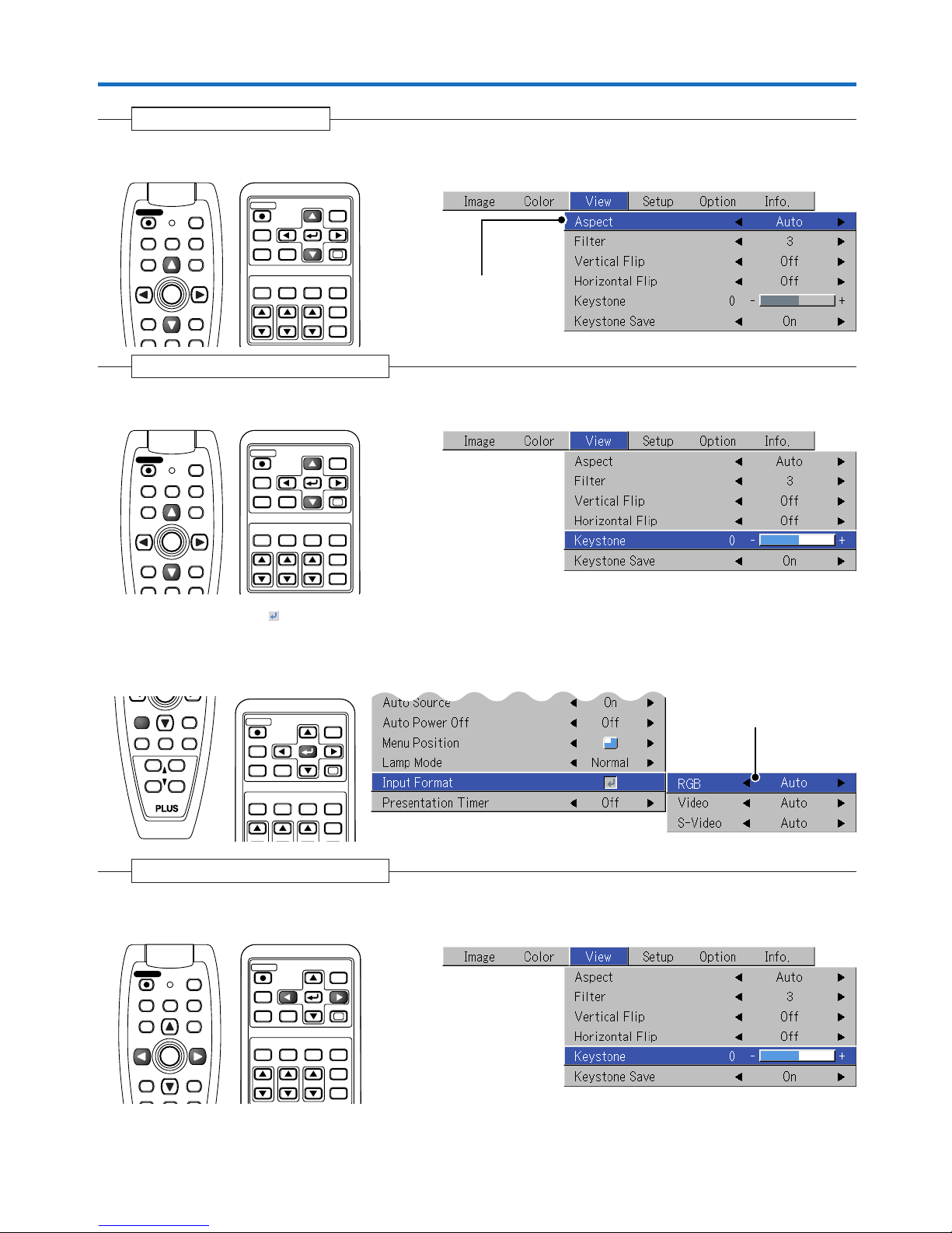
E-43
3 Press the 왔 SELECT button to display the item name selection cursor.
Displaying the Cursor
This condition allows selection of the
item name.
RGB
STANDBY
VIDEO
FREEZE
MUTE
ECO AUTO
ASPECT
TIMER
VOL KSTN ZOOM
CANCEL QUICK
MENU
ENTER
Q
1234
FREEZE
MUTE
LASER
AUTO
TIMER
RGB
VIDEO
R-CLICK/
CANCEL
QUICKMENU
ENTER
STANDBY
Q
Menu Operation Method
4
Press the SELECT (왖왔) button to align the cursor with the item name
Selection of the Item Name
RGB
STANDBY
VIDEO
FREEZE
MUTE
ECO AUTO
ASPECT
TIMER
VOL KSTN ZOOM
CANCEL QUICK
MENU
ENTER
Q
1234
FREEZE
MUTE
LASER
AUTO
TIMER
RGB
VIDEO
R-CLICK/
CANCEL
QUICKMENU
ENTER
STANDBY
Q
Items for which the Icon Is Displayed
Press the ENTER button to display the submenu.
Press the SELECT (왖왔) button and align the cursor with the desired item name.
There are also some items for which the setting display or the verification display will appear. Please see the various item
descriptions.
RGB
STANDBY
VIDEO
FREEZE
MUTE
ECO AUTO
ASPECT
TIMER
VOL KSTN ZOOM
CANCEL QUICK
MENU
ENTER
Q
1234
FREEZE
MUTE
TIMER
VOL
ZOOM
R-CLICK/
CANCEL
12
34
ENTER
Sub menu
5
Press the SELECT (왗왘) button and make the adjustment (or setting) while viewing the image
When a button is pressed, the image will also change.
Making Adjustments/Settings
Adjustment display: Each press of the button results in a change of 1 point and continued presses cause changes to
proceed in order.
Setting display: The setting contents display changes with each press of the button.
RGB
STANDBY
VIDEO
FREEZE
MUTE
ECO AUTO
ASPECT
TIMER
VOL KSTN ZOOM
CANCEL QUICK
MENU
ENTER
Q
1234
FREEZE
MUTE
LASER
AUTO
TIMER
RGB
VIDEO
R-CLICK/
CANCEL
QUICKMENU
ENTER
STANDBY
Q
Page 44
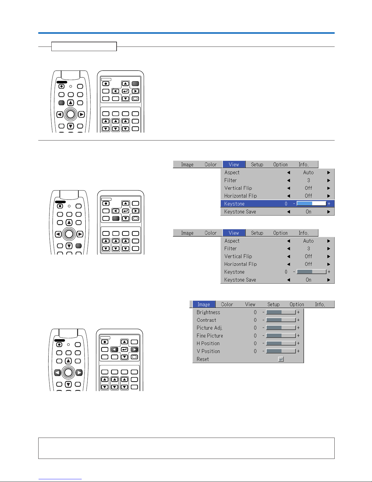
E-44
Menu Operation Method
6
Press the MENU button and close the menu display
Closing the Menu
RGB
STANDBY
VIDEO
FREEZE
MUTE
ECO AUTO
ASPECT
TIMER
VOL KSTN ZOOM
CANCEL QUICK
ENTER
Q
1234
MENU
FREEZE
MUTE
LASER
AUTO
TIMER
RGB
VIDEO
R-CLICK/
CANCEL
QUICK
ENTER
STANDBY
Q
MENU
Selecting Another Menu Name with Remote Control Operation
When a sub menu is displayed, press the CANCEL button and close the sub menu.
Press the CANCEL button again to turn off the item name
cursor.
Press the SELECT (왗왘) button and select the menu
name.
(Menu names cannot be selected when the item name
cursor is displayed.)
Note:
A press of the QUICK button while the menu is displayed will close the menu and display the quick menu. A press of the MENU button while
the quick menu is displayed will close the quick menu and display the menu.
RGB
STANDBY
VIDEO
FREEZE
MUTE
ECO AUTO
ASPECT
TIMER
VOL KSTN ZOOM
CANCEL QUICK
MENU
ENTER
Q
1234
FREEZE
MUTE
LASER
AUTO
TIMER
RGB
VIDEO
QUICKMENU
ENTER
STANDBY
Q
R-CLICK/
CANCEL
RGB
STANDBY
VIDEO
FREEZE
MUTE
ECO AUTO
ASPECT
TIMER
VOL KSTN ZOOM
CANCEL QUICK
MENU
ENTER
Q
1234
FREEZE
MUTE
LASER
AUTO
TIMER
RGB
VIDEO
R-CLICK/
CANCEL
QUICKMENU
ENTER
STANDBY
Q
Page 45
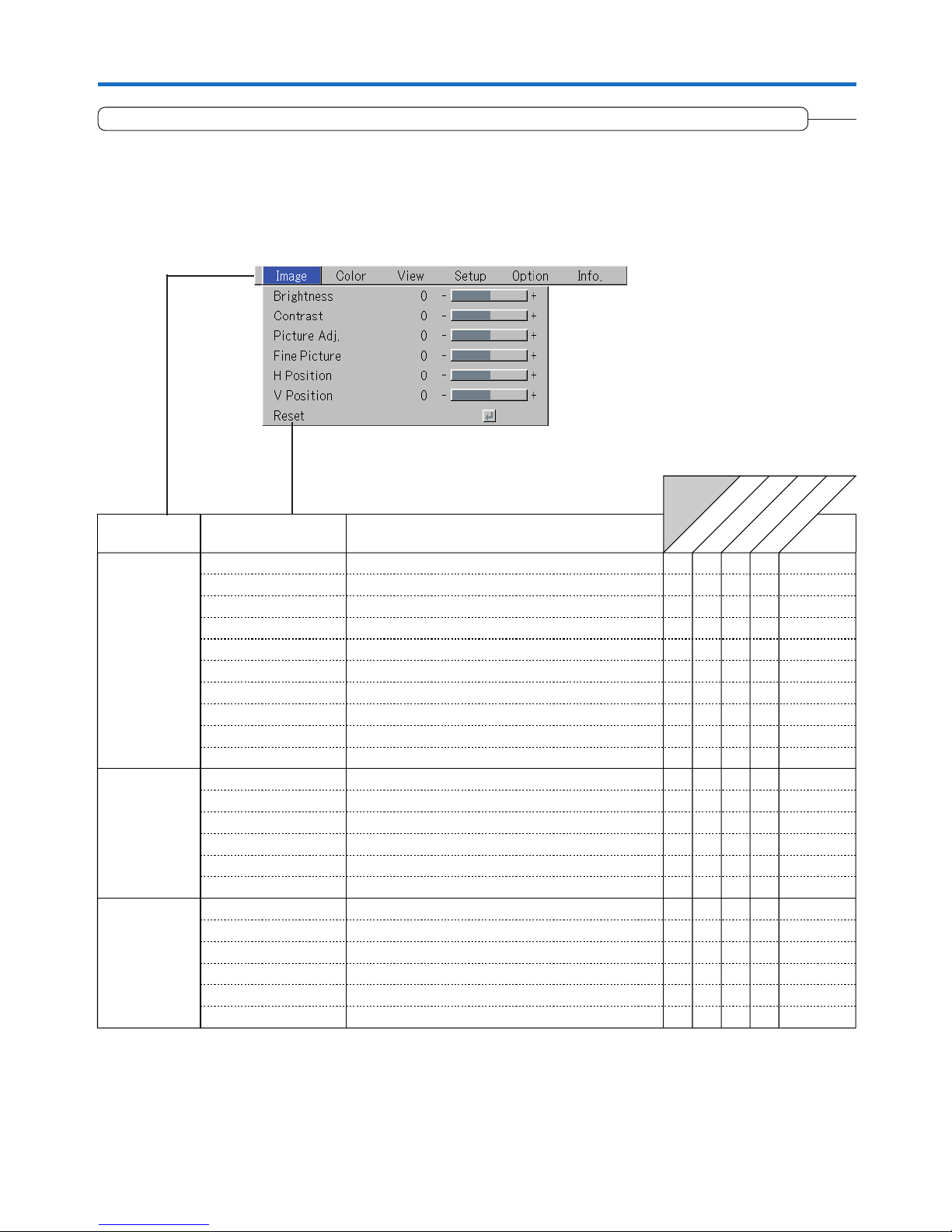
E-45
List of Item Names Offering Input Selection and Adjustments/Settings
The item names that can be adjusted/set will differ depending on the input signal.
“Tint” can be adjusted only at the time of NTSC composite/S signal input.
Menu Operation Method
[Example of Menu Display Items at the Time of Input Signal RGB Selection]
RGB
Component
VIDEO
S-VIDEO
Menu name
Image
Color
View
Brightness E-47
嘷嘷嘷嘷
Item Name
Sub Menu
Item Name
Contrast E-47
嘷嘷嘷嘷嘷
Picture Adj.
Fine Picture
E-47
H Position
E-48
V Position
E-48
嘷
嘷
嘷
嘷
E-48
Reset E-48
嘷嘷嘷嘷
Gamma E-49
嘷嘷嘷嘷
Quick Color Adj. E-49
嘷
Color Temp. E-50
嘷嘷嘷嘷
White E-50
嘷嘷嘷嘷
Color Space
E-50
嘷
White Balance E-51
嘷
Aspect E-52
嘷嘷嘷嘷
Filter E-52
嘷嘷嘷嘷
Vertical Flip E-53
嘷嘷嘷嘷
Horizontal Flip E-53
嘷嘷嘷嘷
Keystone E-53
嘷嘷嘷嘷
Keystone Save E-53
嘷嘷嘷嘷
Reference
Page
Input Signal
Color
Tint
E-47
嘷嘷
Sharpness
E-47
嘷嘷
E-47
嘷嘷
Page 46
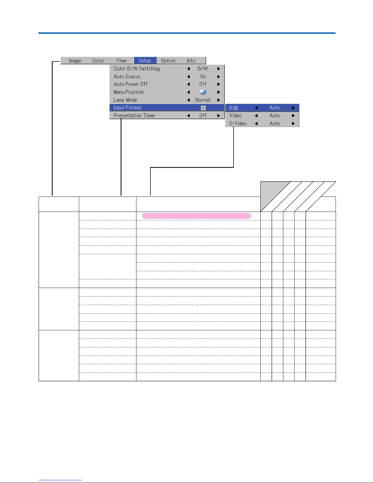
E-46
RGB
Component
VIDEO
S-VIDEO
Menu name
Setup
Info.
Auto Source
E-54
嘷嘷嘷嘷
Color B/W Switching
E-54
嘷嘷嘷嘷
Item Name
Reference
Page
Sub Menu
Item Name
Auto Power Off
E-54
嘷嘷嘷嘷
嘷嘷嘷
嘷嘷嘷
Memu Position
Lamp Mode
E-55
Input Format
E-55
RGB
嘷
嘷
嘷嘷嘷嘷
嘷嘷嘷嘷
嘷嘷嘷嘷
嘷嘷
Video
E-56
S-Video
E-56
Presentation Timer
E-56
E-56
嘷嘷
Language
On Screen
Background
Startup Screen
Option E-57
嘷嘷嘷嘷
E-57
嘷嘷嘷嘷
E-57
嘷嘷嘷嘷
E-58
嘷嘷嘷嘷
Security Lock
E-58
嘷嘷嘷嘷
Status
E-59
嘷嘷嘷嘷
Factory Default
E-59
嘷嘷嘷嘷
Lamp Timer Reset
E-59
嘷嘷嘷嘷
嘷嘷嘷
嘷嘷嘷
Resolution
E-60
嘷
Frequency
E-60
嘷
Lamp Timer
E-60
嘷嘷嘷嘷
Input Signal
Menu Operation Method
Applicable Projector: U5-632h/U5-532h
Page 47
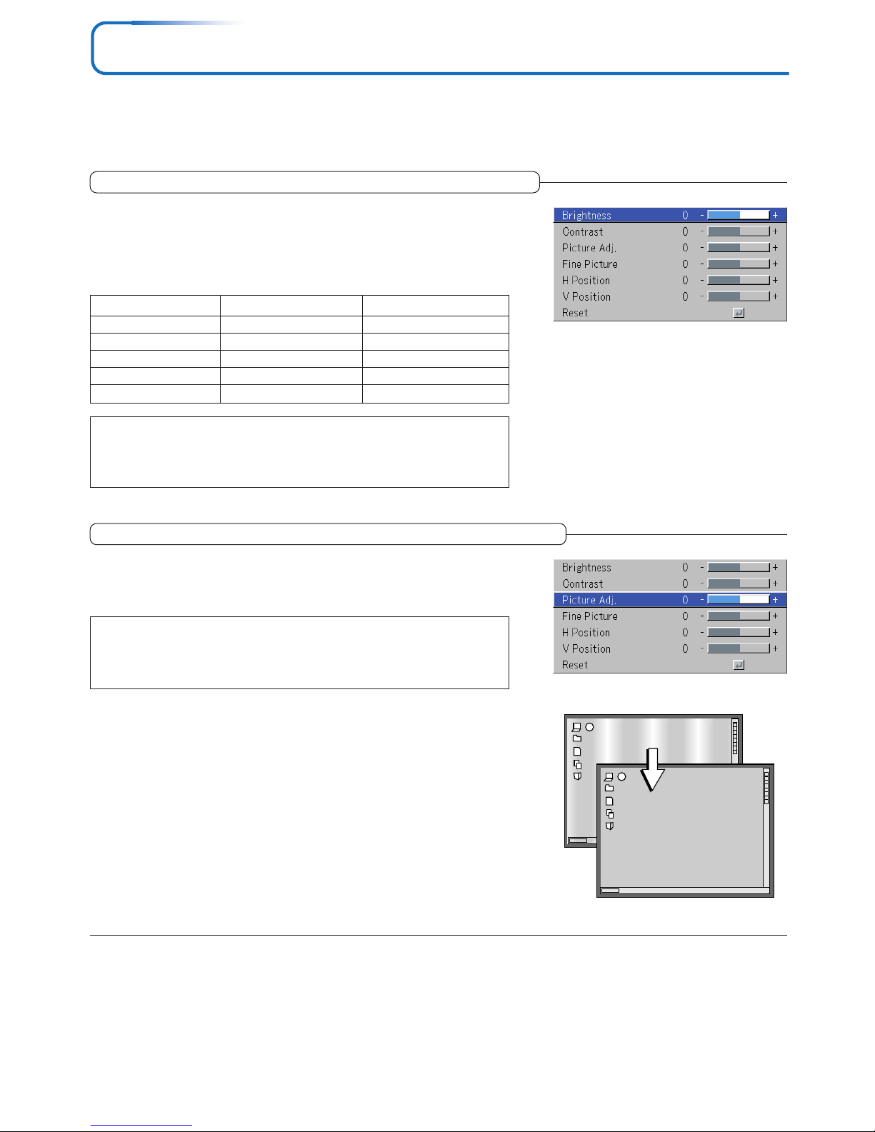
E-47
Image
• Perform this operation while projecting the picture for which the adjustment/setting will be made.
• Select the menu name “Image”.
See “Menu Operation Method” on Page E-40 for information about performing menu operations. The item name display will
differ depending on the input signal. See “List of Item Names Offering Input Selection and Adjustments/Settings” on Page E-45.
Brightness / Contrast / Color / Tint / Sharpness
Picture qualities such as brightness and contrast will change depending on the whether the room is bright or dark. Please adjust to suit your
preference.
Select the desired item name and then adjust with the SELECT (왗왘) buttons.
Item Name
Brightness
Contrast
Color
Tint
Sharpness
SELECT 䊴 Button
SELECT
䊳
Button
Darker
Less contrast
Less dense color
More red
Softer image
Brighter
More contrast
Denser color
More green
Sharper image
Note:
* The adjustment values of the adjustable items are stored according to input source.
* “Tint” can only be adjusted when inputting NTSC composite/S-Video signals or
component signals.
Picture Adj. / Fine Picture / H Position / V Position
Usually, automatic adjustment is performed at the time of signal selection, but when automatic adjustment is not effective, these adjustments
can be performed.
Note:
When the image extends beyond the boundaries of the screen or is smaller than the
screen, check that the “View” → “Aspect” setting is set to “Auto”. See “Aspect” on
Page E-52.
Picture Adj. (Picture Adjustment)
Adjust this when bright and dark vertical bands appear on the screen.
Select the “Picture Adj.” item name and adjust with the SELECT (왗왘) buttons
so that the vertical bands disappear and brightness becomes uniform across
the screen.
Page 48
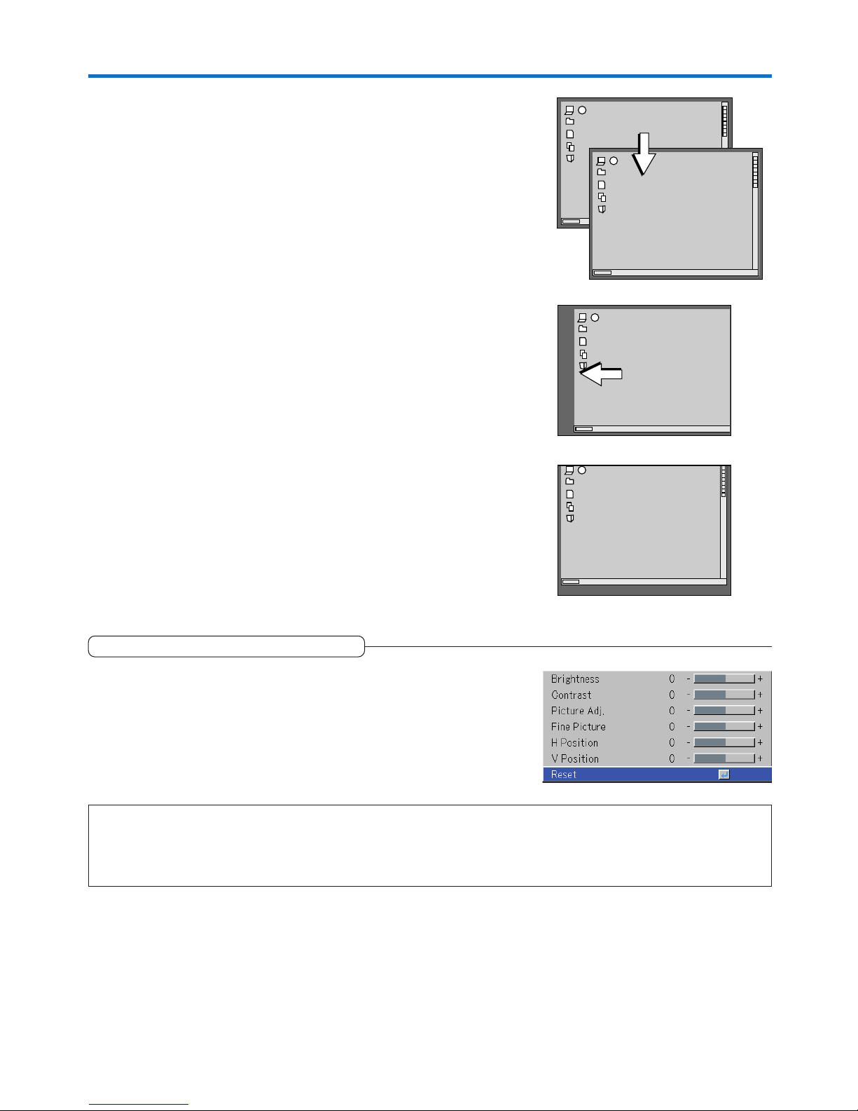
E-48
Fine Picture
Adjust this when the picture shows a lack of color fidelity or flickering.
Select the “Fine Picture” item name and adjust with the SELECT (왗왘) but-
tons so that the lack of color fidelity or the flickering disappears.
Image
V Position
Adjust this when the picture is shifted up or down.
Select the “V Position” item name and adjust with the SELECT (왗왘) buttons.
H Position
Adjust this when the picture is shifted to the left or right.
Select the “H Position” item name and adjust with the SELECT (왗왘) buttons.
Reset
This function resets (i.e., returns to the standard settings) the adjustment/setting value of the “Image” menu name.
A press of the ENTER button forces the reset.
Note:
* The item name “Fine Picture” at the time of RGB input will not be reset.
* “Reset” of the menu name “Image” can be reset for each input source.
* To reset the adjustments/settings of all the menu items (while noting that there are some items that cannot be reset), see “Factory Default”
on Page E-59.
Page 49
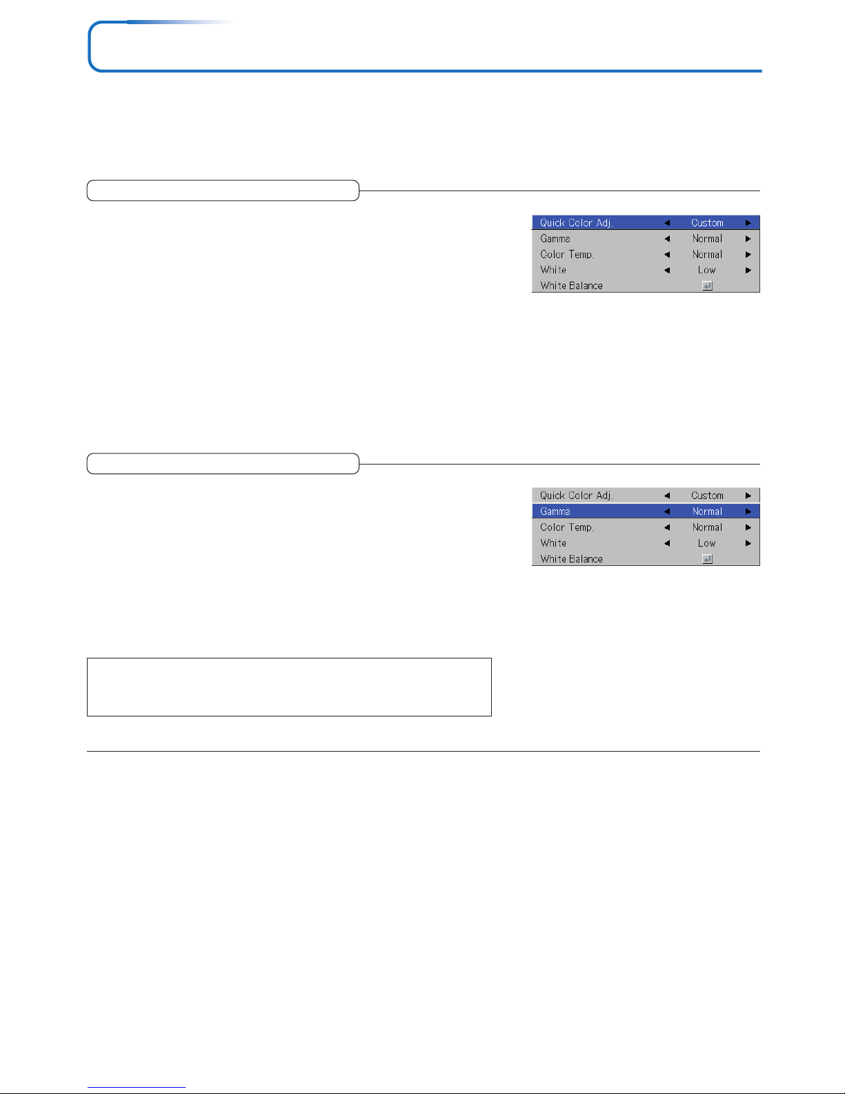
E-49
Color
• Do the following operation while displaying the image you want to adjust or set.
• Select the menu name “Color”.
See “Menu Operation Method” on Page E-40 for information about performing menu operations. The item name display will
differ depending on the input signal. See “List of Item Names Offering Input Selection and Adjustments/Settings” on Pages
E-45.
Quick Color Adj.
Select the preset color mode.
Select the “Quick Color Adj.” item name and select the setting contents with
the SELECT (왗왘) buttons.
Picture ........ Select this to prioritize color.
Standard ..... This is the standard selection. (Default setting)
Dynamic ..... Select this for prioritizing brightness.
* When “Picture”, “Standard” or “Dynamic” is selected, the “Gamma”, “Color Temp.” and “White”
adjustment items are displayed in gray and cannot be selected or adjusted.
Custom ....... “Gamma”, “Color Temp.” and “White” adjustment items can be selected
and adjusted
* The selected values for the different adjustment items are stored in the memory so the desired
color adjustments can be set.
Gamma
Gamma corrects the proportion of change of the dark portions from the
bright portions of the input signal.
Set this to reproduce natural color tone or to distinctly project a personal computer picture in a bright conference room.
Select the “Gamma” item name and select the setting contents with the SELECT
(왗왘) buttons.
Normal ....... Correction with standard settings
Natural ........ Corrects for natural color tones
Real ............ Corrects with emphasis on brightness
Note:
When “Picture”, “Standard” or “Dynamic” is selected for “Quick Color Adj.”, the
“Gamma” adjustment item is displayed in gray and cannot be selected or adjusted.
Page 50
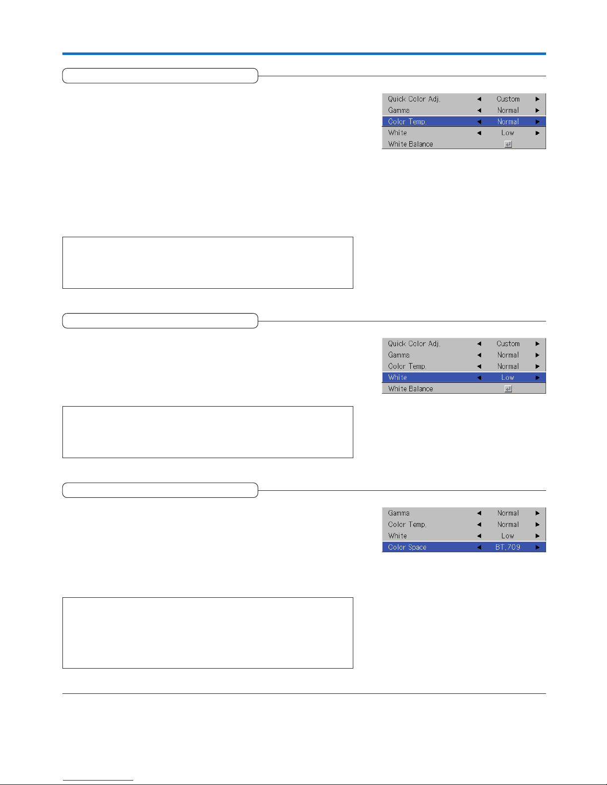
E-50
Color
Color Temp.
The screen color is affected by the color of the illumination and other
extraneous light.
This function adjusts the white, which is the reference color for video
equipment, and improves the quality of color reproduction. Adjustment
can also be used to enhance skin colors.
Select the item name “Color Temp.” and select the setting contents with the
SELECT (왗왘) buttons.
Low ............ Produces warm whites (reddish)
Medium ...... Produces warm whites (yellowish)
Normal ....... Produces the white of sunlight
High ............ Produces cool whites (bluish)
Note:
When “Picture”, “Standard” or “Dynamic” is selected for “Quick Color Adj.”, the
“Color Temp.” adjustment item is displayed in gray and cannot be selected or ad-
justed. See “Quick Color Adj.” on E-49.
White
When projecting, this function is used to emphasize the whites of text or
diagrams on the personal computer.
Select the item name “White” and use the SELECT (왗왘) buttons to select the
setting contents.
Select the desired degree of white from among “Low”, “Medium”, and “High”.
Note:
When “Picture”, “Standard” or “Dynamic” is selected for “Quick Color Adj.”, the
“White” adjustment item is displayed in gray and cannot be selected or adjusted.
See “Quick Color Adj.” on E-49.
Color Space
Set this function when a component signal (YPbPr) is projected and the
image is extremely red or extremely green.
Select the item name “Color Space” and use the SELECT (왗왘) buttons to
select a color space setting that provides a normal image.
Selection contents at the time of YPbPr input
BT.709, SMPTE240
Note:
* When the component signal undergoes conversion processing to red, green,
and blue which express the image of the projector, the correct color cannot be
reproduced unless a system compliant with the color difference conversion system of the input signal is used. Color Space serves to make this selection.
* The color space can only be adjusted with high definition TVs.
Page 51
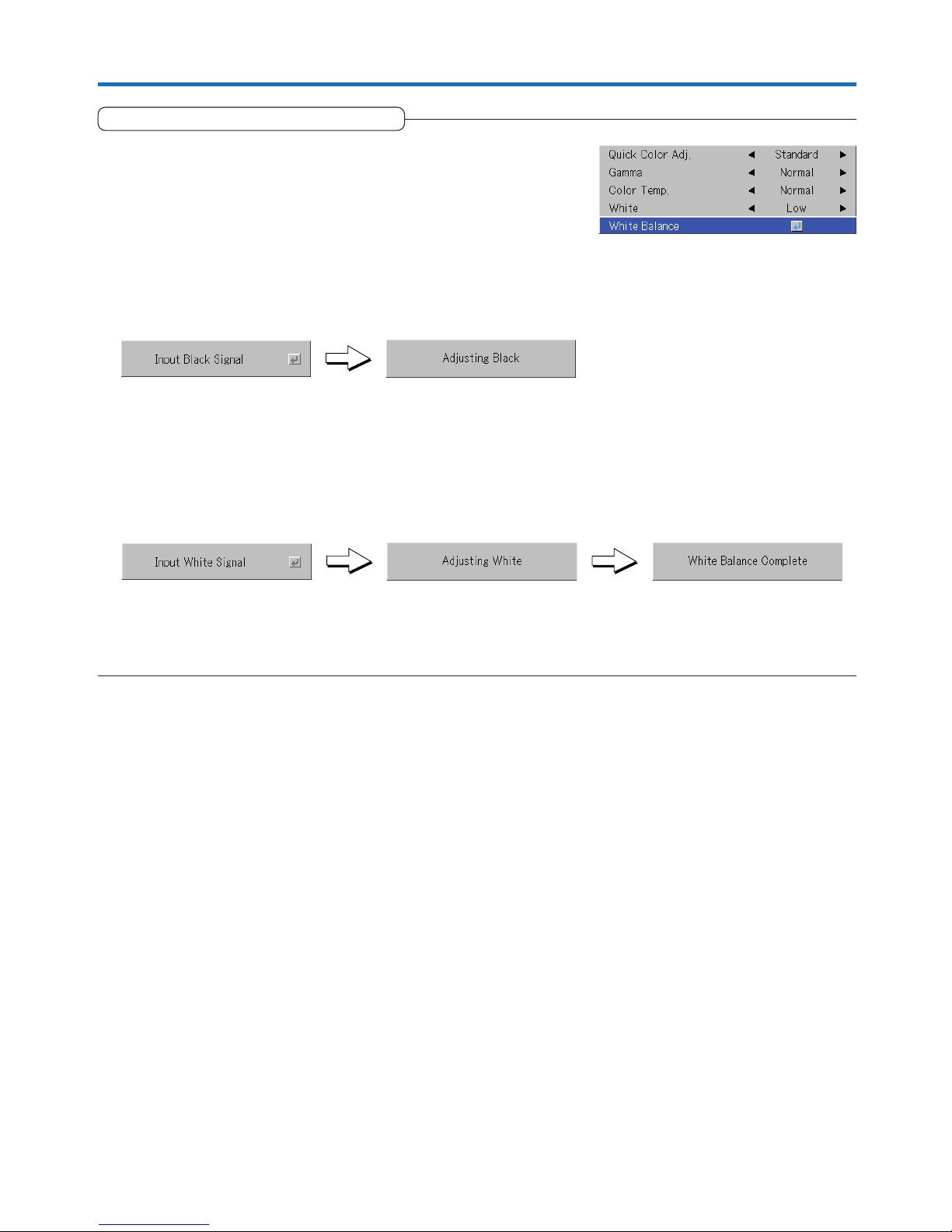
E-51
White Balance
Color
This function automatically adjusts the black level and the white level of
the analog RGB input signal to suit the personal computer.
1 Select the item name [White Balance] and press the ENTER button.
The display will change to [Input Black Signal].
2 The screen background color of the connected personal computer
will be set to black.
3. Press the ENTER button. The display will change to [Adjusting Black]
and the black level will be adjusted.
4 The adjustment of the black level is completed and the display
changes to [Input White Signal].
5 The screen background color of the connected personal computer
will be set to white.
6 Press the ENTER button. The display will change to [Adjusting White]
and the white level will be adjusted.
[White balance complete] is displayed for a while and the adjustment is
completed.
Page 52
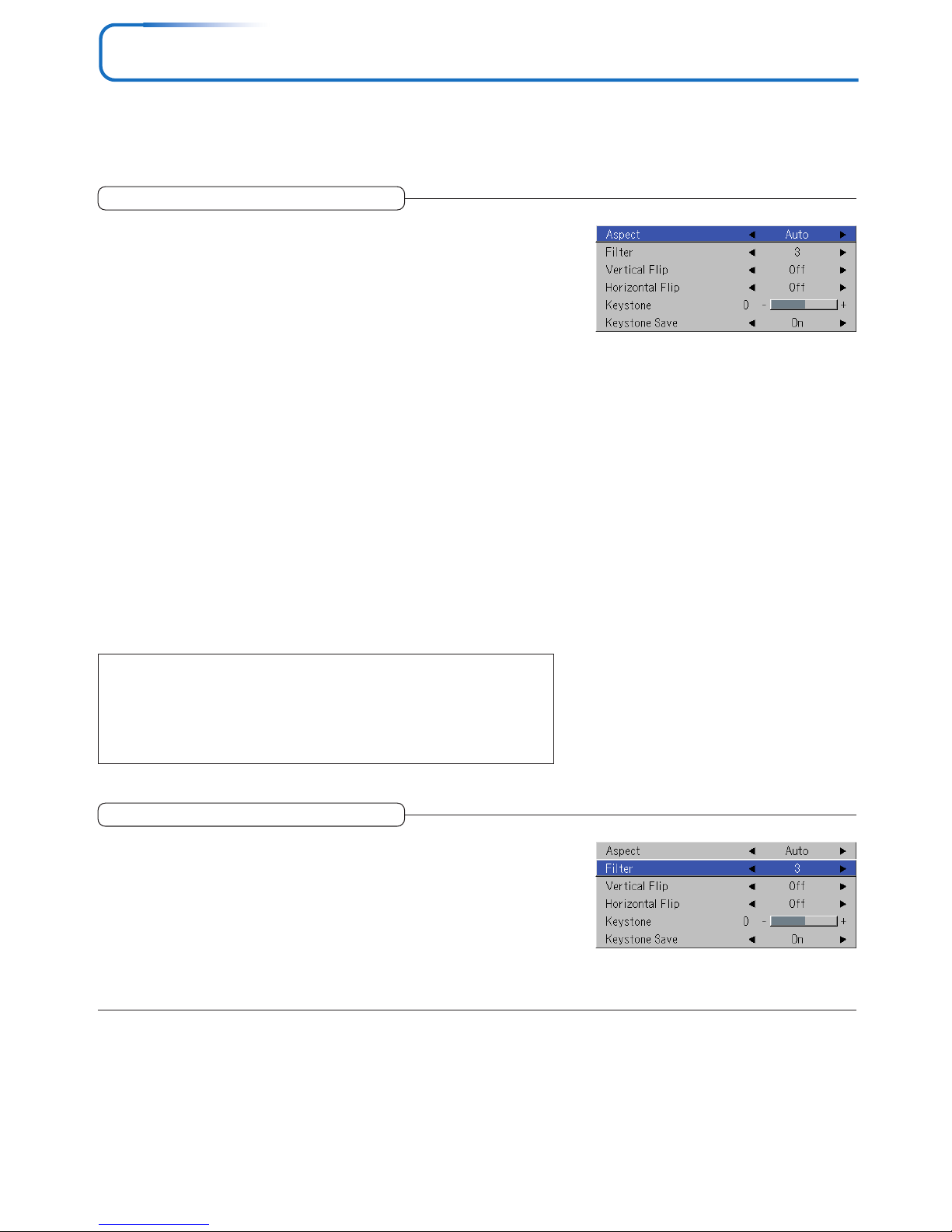
E-52
View
• Perform this operation while projecting the picture for which the adjustment/setting will be made.
• Select the menu name “View”.
See “Menu Operation Method” on Page E-40 for information about performing menu operations. The item name display will
differ depending on the input signal. See “List of Item Names Offering Input Selection and Adjustments/Settings” on Page E-45.
Filter
This function sets the sharpness when the input signal is adjusted to
the resolution of the projector and enlarged or reduced.
Select the item name “Filter” and select the setting contents with the SELECT
(왗왘) buttons.
Smaller numerical values result in a sharper picture and larger values result in
a softer picture. Please select your desired setting value.
Aspect
This function sets the horizontal and vertical picture proportions of the
input signal.
Select the item name “Aspect” and select the setting contents with the SELECT
(왗왘) buttons.
Personal Computer Signal
Auto ............ Automatically enlarges or reduces the image to project a full screen in a
ratio of 4:3
Direct .......... Maintains the aspect ratio and projects a picture of the maximum
displayable size
Real ............ Projects the input signal without pixel conversion
Video Signals
Auto ............ While maintaining the aspect ratio, projects a full screen so that no por-
tions extend beyond the boundaries of the screen. The top and bottom of
the 16:9 image becomes black.
Wide ........... Projects to fill the full width with the entire image at 16:9.
(This feature is used to project a squeezed image in a proper aspect ratio.)
Zoom .......... Projects only the 4:3 portion within 16:9 image to fill the screen.
(Portion that extend off screen is cut.)
See “Selection of Aspect Ratio” on Page E-29 for diagrams of projection screen
images that correspond to the input signals.
Note:
Please note that using this monitor for the purpose of commercial gain or the attraction of public attention in a venue such as a coffee shop or hotel and projecting
a 4:3 screen in wide mode or leaving a squeezed screen as a compressed image
raises concern about the infringement of the copyright holder’s rights which are
protected by copyright law.
Page 53
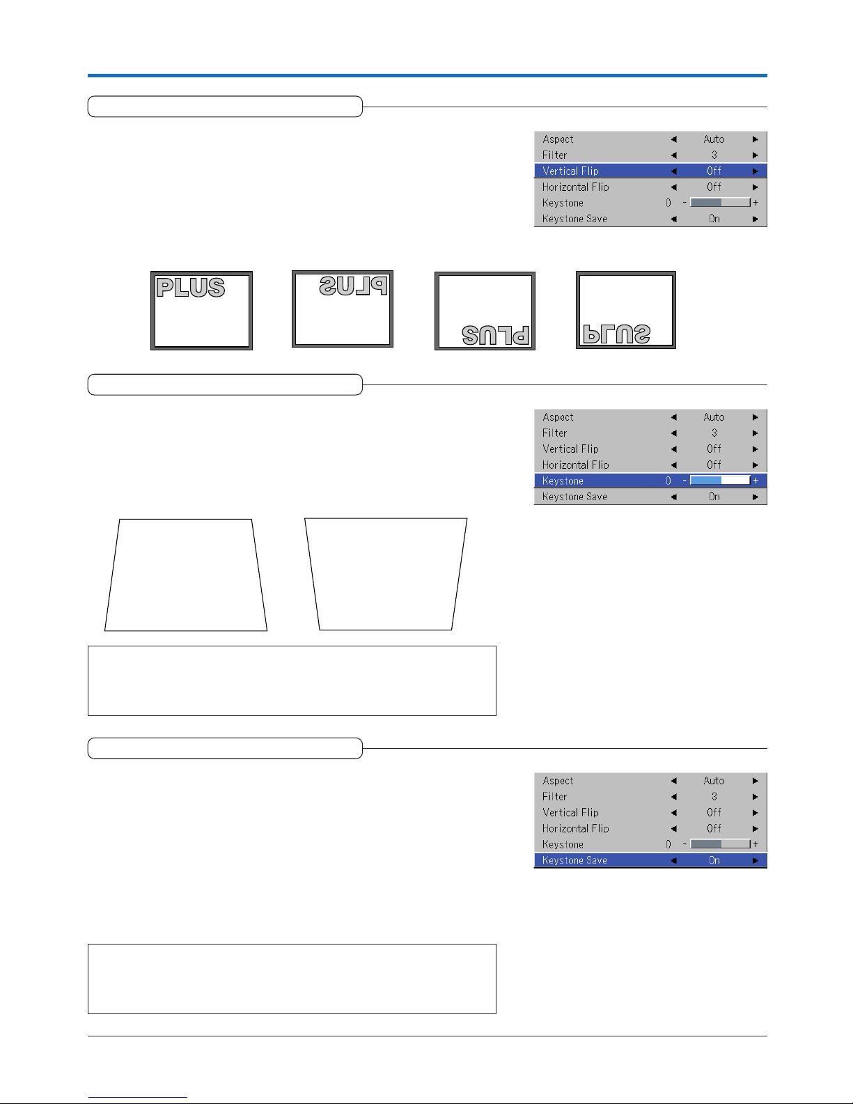
E-53
View
“Vertical Flip” Off
“Horizontal Flip” Off
“Vertical Flip” Off
“Horizontal Flip” On
“Vertical Flip” On
“Horizontal Flip” On
“Vertical Flip” On
“Horizontal Flip” Off
Vertical Flip
In selecting the method of projecting to the screen, these functions are
set when the projector is in a suspended or a rear screen installation.
Select the item name “Vertical Flip” or “Horizontal Flip” and select the setting
contents with the SELECT (왗왘) buttons.
Keystone Save
This function is used to save the keystone adjustment values.
Setting Keystone Save to on will set the previous keystone adjustment values
when projecting after the power cable has been disconnected and then reconnected.
Select the item name “Keystone Save” and set with the SELECT (왗왘) buttons.
Off .............. The keystone adjustment values return to the initial values when the power
cable is unplugged.
On ............... The keystone adjustment values are retained in storage even when the
power cable has been unplugged.
Note:
Regardless of whether Keystone Save is set to “On” or “Off”, when projection is
from the standby condition, the picture is projected using the previous keystone
adjustment values.
Note:
* The menus and other on-screen displays cannot be adjusted.
* Please note that depending on the projected picture and the projection condi-
tions, it may not be possible to eliminate keystone distortion completely.
Press the 왗 button. Press the 왘 button.
Keystone
Keystone distortion will occur when the projector and screen are on an
angle (in the vertical orientation). This function is used to correct this
distortion.
Select the item name “Keystone” and correct the keystone distortion using the
SELECT (왗왘) buttons.
Page 54
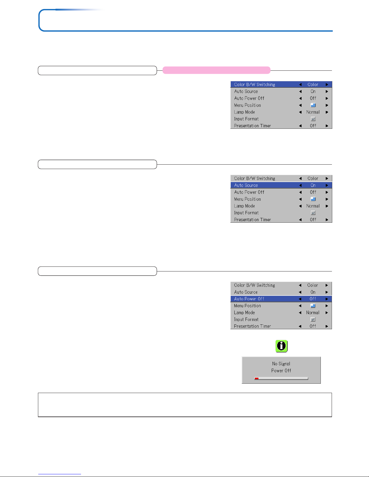
E-54
Setup
• Select menu name “Setup”.
See “Menu Operation Method” on Page E-40 for information about performing menu operations. The item name display will
differ depending on the input signal. See “List of Item Names Offering Input Selection and Adjustments/Settings” on Page E-45.
Auto Power Off
This function switches off the projector power automatically when the
input of the projector enters a no-signal condition.
Select item name “Auto Power Off” and select the setting contents with the
SELECT (왗왘) buttons.
On ............... The power is switched off when there is no signal.
Off .............. The power is not switch off even when there is no signal.
Operation when Function is On
• The “No Signal Power Off” display appears when a no-signal condition con-
tinues for approximately 10 seconds. The power is switched off about 5
minutes after this.
• If a signal is input during the appearance of the display and an operation
button other than the STANDBY button is pressed, the display is closed and
the function is cancelled.
Note:
Some video decks and other equipment output a blue background or other video when playback ends. When this happens, a signal is being
input to the projector and Auto Power Off is not activated.
Auto Source
The Auto Source function automatically detects the input signal when
the power supply is switched on and when the input is switched.
Select the item name “Auto Source” and select the setting contents with the
SELECT (왗왘) buttons.
On ............... Switches on the automatic detection function
Off .............. Switches off the automatic detection function
Signal Detection Order When On
The sequence of RGB → VIDEO → S-VIDEO is searched repeatedly.
When a signal is detected, the search is stopped and the image is projected.
Color B/W Switching
Documents, spreadsheets or other mostly black and white data can be
projected with stronger brightness.
It is possible to switch between the black/white and color mode while an
image is being projected.
Select the “Color B/W Switching” item name, then use the 왗 and 왘 SELECT
buttons to select the desired setting.
Color ........... The color image projection mode is set.
B/W ............ The high brightness black/white image projection mode is set.
Applicable Projector: U5-632h/U5-532h
Page 55
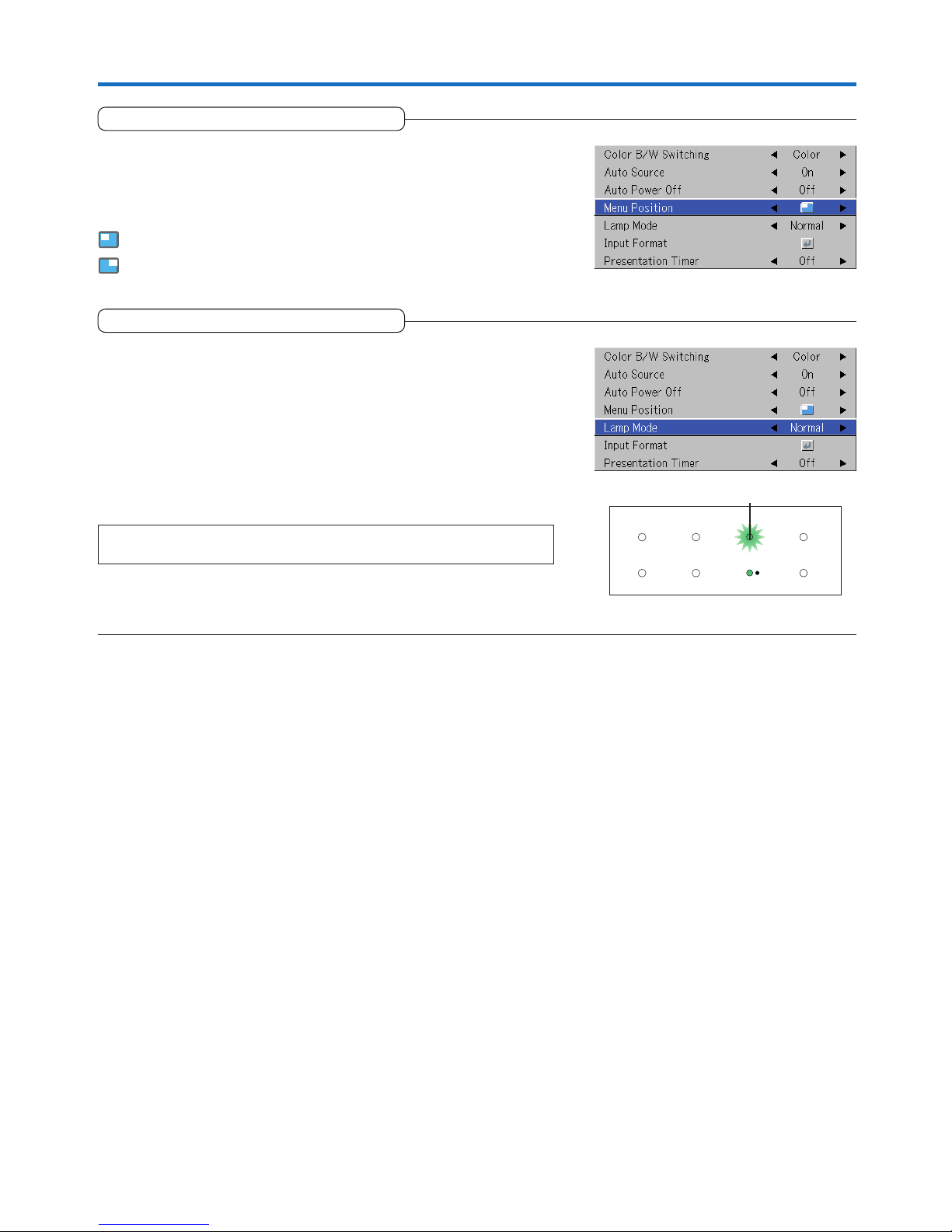
E-55
Setup
Menu Position
This function sets the display position of the menu.
Select item name “Menu Position” and select the setting contents with the
SELECT (왗왘) buttons.
............. Displays on the left side
............. Displays on the right side
Lamp Mode
Use this if the picture is projected on a small screen and the picture is
too bright or when projecting images in dark rooms.
Select the item name “Lamp Mode” and select the setting contents with the
SELECT (왗왘) buttons.
Eco ............. The lamp brightness is set to 80% and the lamp life is extended.
(STATUS indicator is green)
Normal ....... The lamp brightness is set to 100% and the screen is bright.
(STATUS indicator is off)
Note:
Frequent switching this mode can degrade the lamp.
STANDBY
STATUS
STATUS Indicator
Page 56
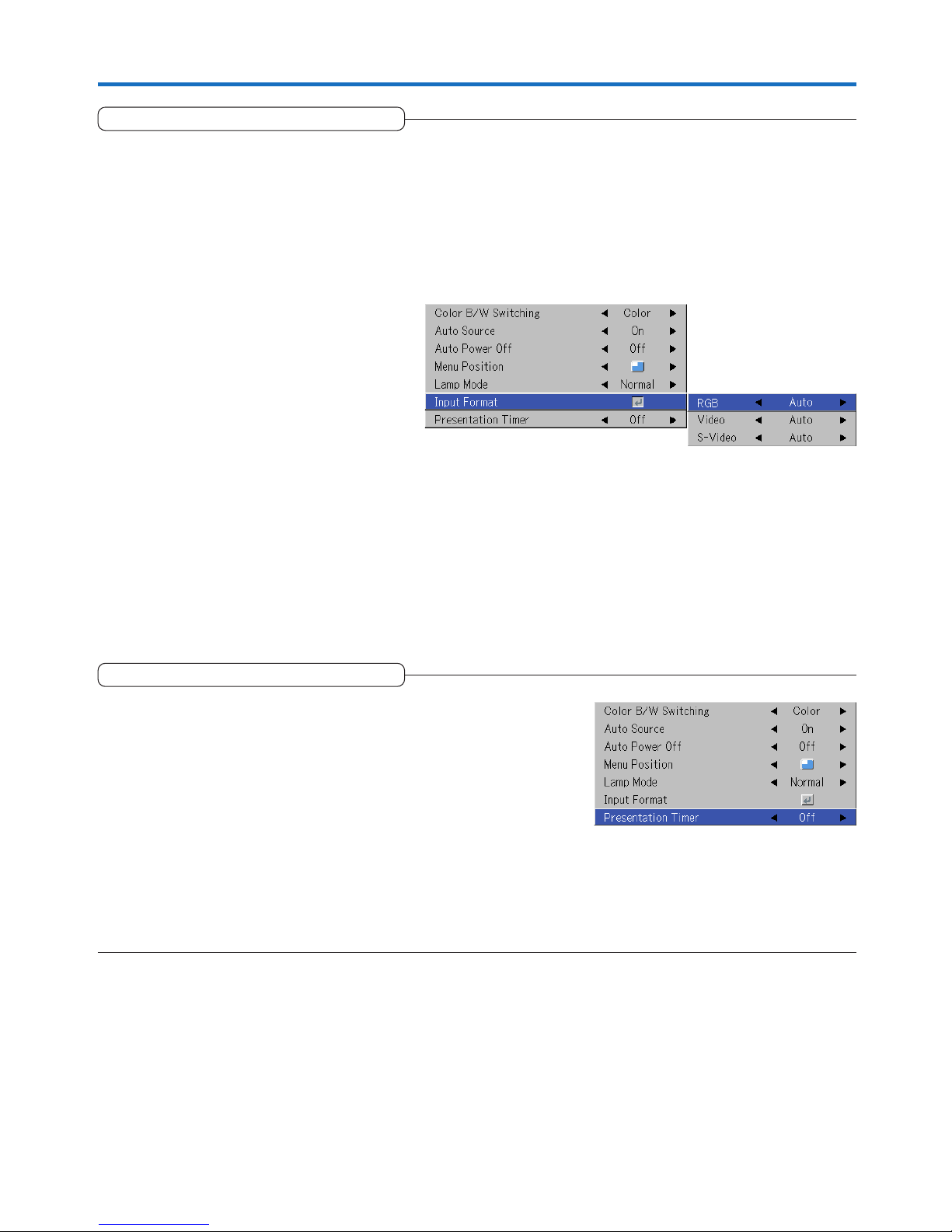
E-56
Setup
Input Format
This function is used in setting the input signals of the input connectors.
Normally, this should be set to Auto. When identification is not possible
with Auto, make the setting.
Select the item name “Input Format”, press the ENTER button, and the sub
menu will open.
Select the connector that is to be changed, and select the setting contents
with the SELECT (왗왘) buttons.
[RGB]
This is the signal setting for the RGB connector.
Auto ............ Automatically identifies the signal.
RGB ............ Analog RGB signal is set.
Component . Component signal is set.
[Video] and [S-Video]
[Video] is the color system setting for the VIDEO connector and [S-Video] is
the color system setting for the S-VIDEO connector.
Auto ............ Automatic identification.
NTSC .......... Fixed to the NTSC system.
NTSC 4.43 .. Fixed to the NTSC 4.43 system.
PAL ............. Fixed to the PAL system.
PAL M......... Fixed to the PAL M system.
PAL N ......... Fixed to the PAL N system.
PAL 60 ........ Fixed to the PAL 60 system.
SECAM ....... Fixed to the SECAM system.
Presentation Timer
The presentation is given while checking the timer displayed on the
screen.
The gauge display allows the remaining time to be known at a glance.
Select the item name “Presentation Timer” and select the setting contents
with the SELECT (왗왘) buttons.
Setting contents: Off, 10 min., 20 min. , 30 min., 40 min., 50 min., 60 min.
To start the timer...
Press the MENU button and open the menu.
The timer display will appear at the lower right and the timer will start.
See “Using the Presentation Timer” on Page E-33 for details.
Page 57
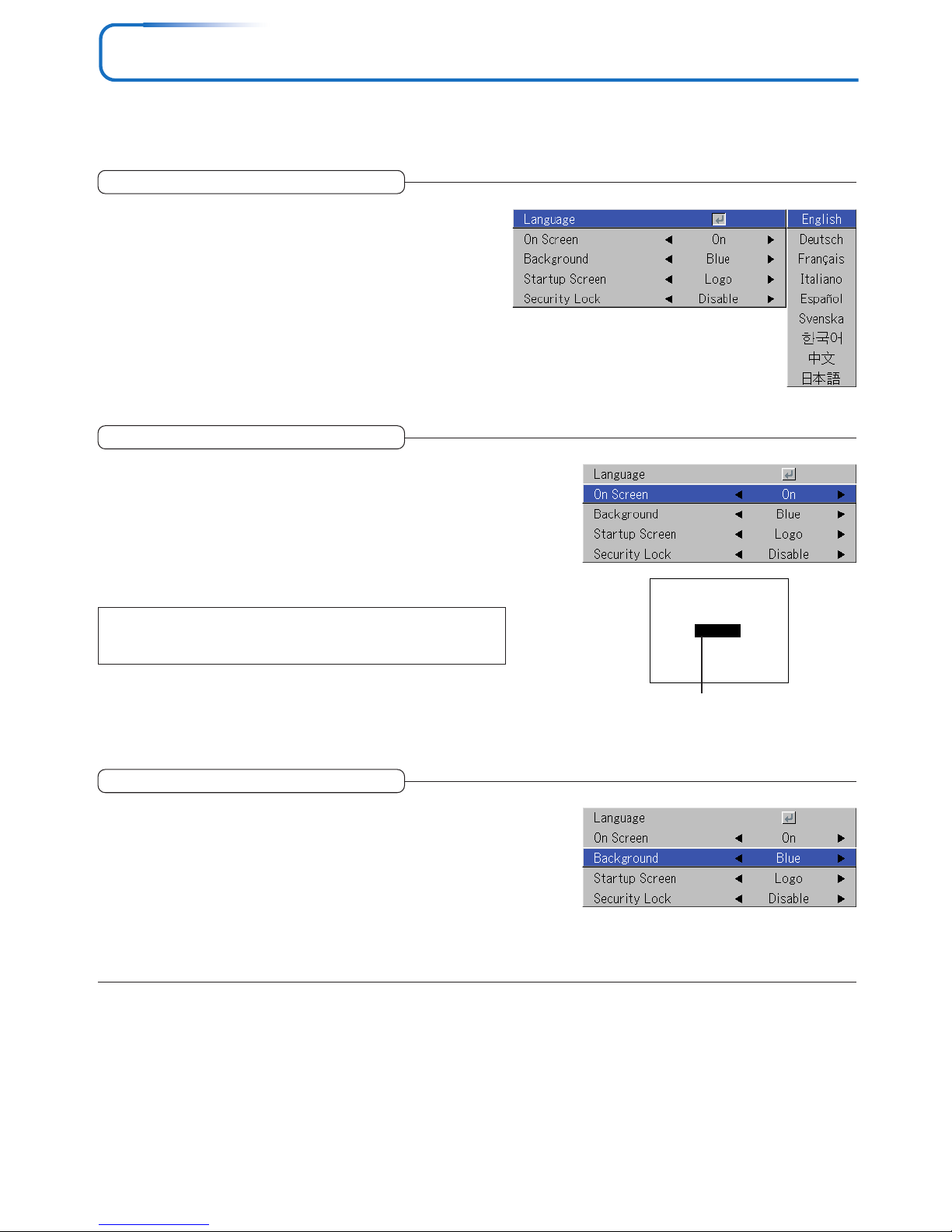
E-57
Option
• Select menu name “Option”.
See “Menu Operation Method” on Page E-40 for information about performing menu operations. The item name display will
differ depending on the input signal. See “List of Item Names Offering Input Selection and Adjustments/Settings” on Page E-45.
Language
This function sets the language that is displayed on screen in
the messages and menu displays.
Select item name “Language” and press the ENTER button to open
the Language sub menu.
Select the language with the SELECT (왖왔) buttons.
On Screen
Example of a display when the
FREEZE button is pressed
Freeze
This function switches on/off the messages displayed with a black
frame such as the input signal information and the aspect ratio.
Select item name “On Screen” and select the setting contents with the
SELECT (왗왘) buttons.
On ............... The message is displayed.
Off .............. The message is not displayed.
Note:
Even when set to off, messages that are not in a black frame will be displayed.
Background
This function sets the screen color when the input source is nosignal.
Select item name “Background” and select the setting contents with
the SELECT (왗왘) buttons.
Blue ............ Sets a blue screen when there is no signal
Black ........... Sets a black screen when there is no signal
Page 58
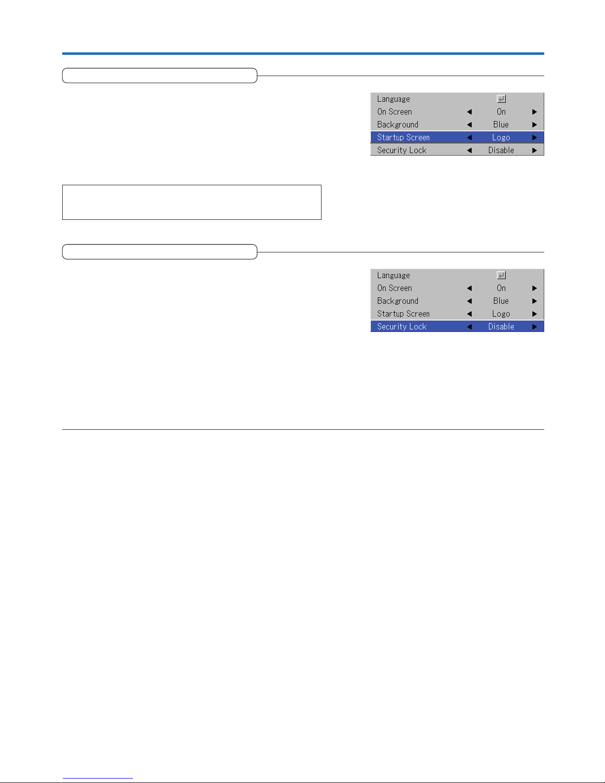
E-58
Startup Screen
Option
This is the selection of whether or not to display the logo screen
at startup time.
Select item name “On Screen” and select the setting contents with the
SELECT (왗왘) buttons.
Logo ........... Displays the logo.
Blank .......... Does not display the logo.
Note:
When “Logo” is selected at the startup screen, the “PLUS” logo is displayed.
Security Lock
A password can be registered and the security lock set in order
to prevent unauthorized use of the projector.
For instructions on using the security function, see “Protecting the
Projector with the Security Lock” on E-37.
Select item name “Security Lock” and select the setting contents with
the SELECT (왗왘) buttons.
Disable ....... The security lock is disabled.
The projector can be operated without inputting the password.
Enable ......... The security lock is enabled.
The security lock is activated when the power is turned on, and
the password must be input in order to operate the projector.
Page 59
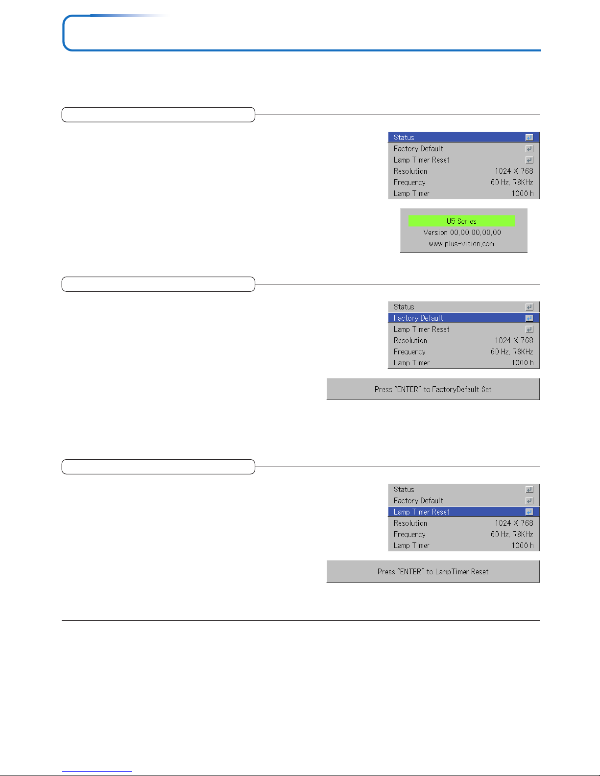
E-59
Info.
• Select menu name “Info.”.
See “Menu Operation Method” on Page E-40 for information about performing menu operations. The item name display will
differ depending on the input signal. See “List of Item Names Offering Input Selection and Adjustments/Settings” on Page E-45.
This displays information about the equipment.
Select item name “Status” and press the ENTER button.
There is a change to the status display.
Press the CANCEL button to return to the menu.
Display Contents:
Projector model, firmware version, and the internet home page address of PLUS Vision Corp.
Status
This function returns the adjustments and settings of all the input sources to the standard factory default values.
Select item name “Factory Default” and press the ENTER button.
There is a change to the display [Press “ENTER” to Factory Default
Set].
Press the ENTER button to initialize.
To cancel, press the CANCEL button and there will be a return to the
menu.
Items that are not set to the factory default:
Projection method, Language and Lamp Timer and Security.
Factory Default
This function resets the lamp timer. Be sure to perform the reset
operation when the lamp cartridge has been replaced.
Select item name “Lamp Timer Reset” and press the ENTER button.
There is a change to the display “Press “ENTER” to Lamp Timer Re-
set”.
Press the ENTER button to initialize.
To cancel, press the CANCEL button and there will be a return to the
menu.
Lamp Timer Reset
Page 60
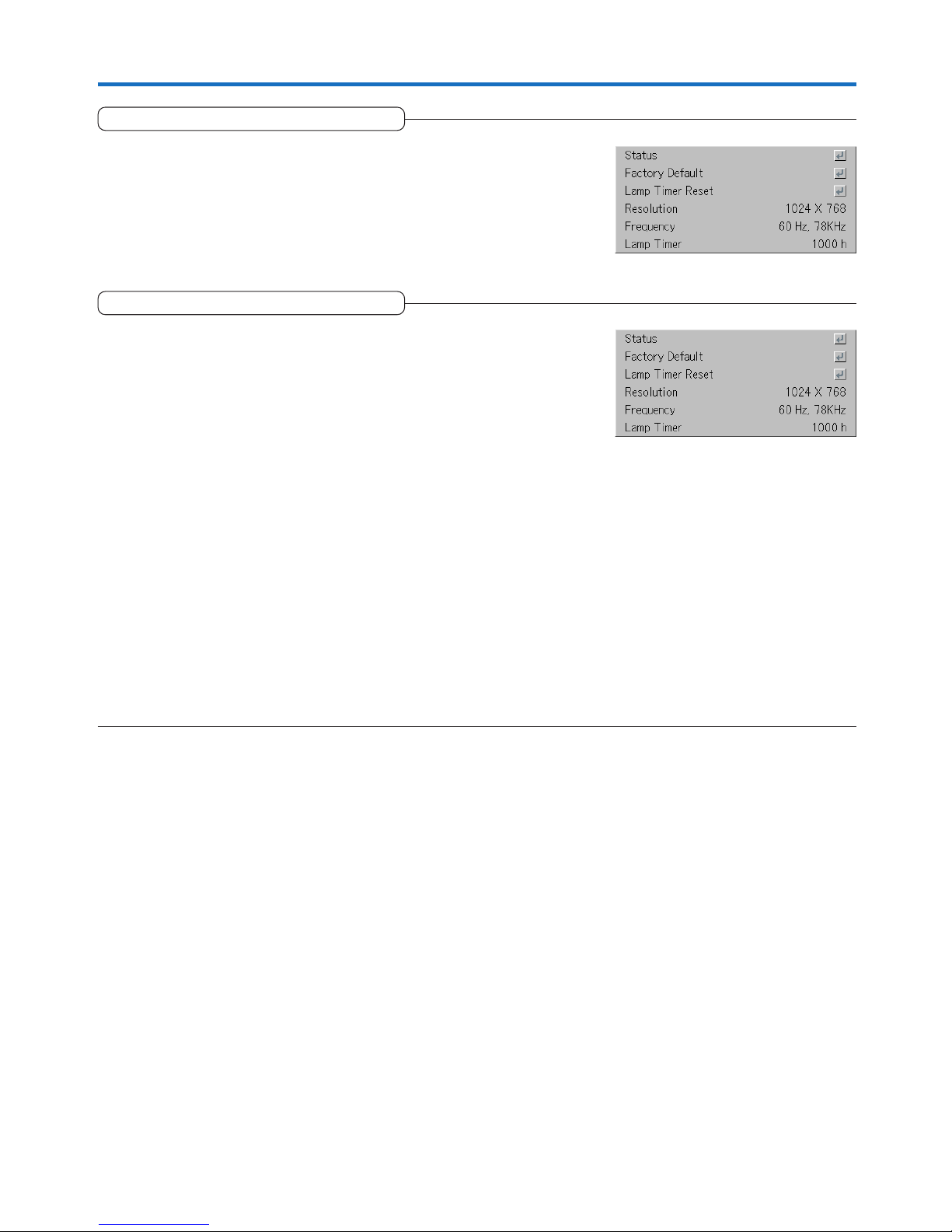
E-60
Info.
This function displays the resolution and frequency of the detected input signal.
Resolution / Frequency
This displays the lamp timer.
This projector has an Eco mode function. The lamp life will differ between
Normal mode and Eco mode.
Lamp Life
Use only in Normal mode: approx.2000 hours
Use only in Eco mode: approx.3000 hours
* Lamp life will differ when there has been switching between the modes.
• When Lamp Life Has Been Reached
“Replace the Lamp Cartridge” is displayed on the screen for 10 seconds in
a 1-minute interval.
Please replace the lamp with a new one.
See “Replacing the Lamp Cartridge” on Page E-64 for information about
lamp cartridge replacement.
• When Over 100 Hours Have Elapsed Since Reaching Lamp Life
(Including Eco Mode)
[Warning!! System Shutdown] is displayed for 10 seconds and the power is
switched off. Pressing the STANDBY button under this condition will not
switch on the power. Please replace the lamp cartridge.
Lamp Timer
Page 61
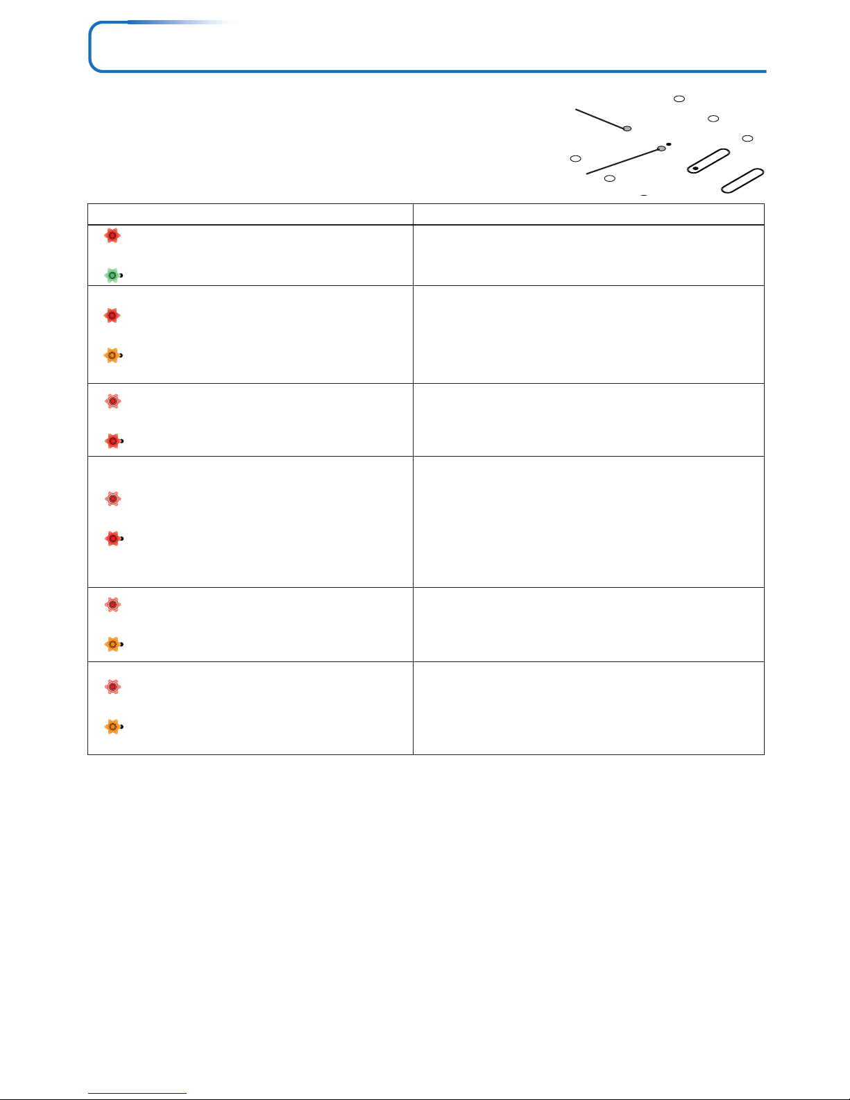
E-61
When an Indicator is Lit or Flashing
STANDBY
STATUS
STANDBY
AUTO
STATUS
STANDBY
STATUS
STANDBY
STATUS
STANDBY
STATUS
STANDBY
STATUS
STANDBY
The indicators on the projector’s control panel light or flash to
notify of problems, as described below.
An indicator is also used to notify you of the currently set power
mode (under normal circumstances). See “Power Cable Con-
nections and Switching the Power On/Off” on page E-23.
STATUS indicator
Indicator status What you should do
Lit red
When the power is on (Lit green)
Standby (Lit amber)
Lit red
Flashing amber for 60 seconds, then lit amber
Flashing red
(lit for 1 seconds/off for 1 seconds)
Lit red
Flashing red
(lit for 0.5 seconds/off for 0.5 seconds)
Lit red
Flashing red
(lit for 0.5 seconds/off for 0.5 seconds)
Lit amber
Flashing red
(lit for 1 seconds/off for 1 seconds)
When the lamp has burned out during use
Flashing amber for 90 seconds, then lit amber
When the lamp does not come on from the start
Lit amber
It is time to replace the lamp.
Replace with a new lamp cartridge.
The lamp has reached the end of its service life. The power
will no longer turn on.
The projector can be used for 100 hours after the lamp has
reached the end of its service life.
Replace with a new lamp cartridge.
The lamp cover is open.
The lamp cover is not properly mounted. Mount it properly.
The temperature is abnormally high.
• The temperature protector has been activated. If the room
temperature is high, move the projector to a cool place. If
the projector’s internal temperature is high, check the cooling fan’s ventilation slots and clean them if they are clogged.
• When the temperature protector is activated, the power turns
off and in some cases will not turn back on immediately. In
this case wait about 90 seconds, then try again.
The fan has stopped.
Unplug the power cable and contact a store that sells the U5632h/U5-732h/U5-532h/U5-512h for repairs.
The lamp will not light.
Wait at least 90 seconds, then turn the power back on. If the
problem persists, unplug the power cord and contact a store
that sells the U5-632h/U5-732h/U5-532h/U5-512h for repairs.
STATUS
STANDBY
STANDBY indicator
Should an indicator be in a condition other than normal or flash at a rate other than the aforementioned, disconnect the power
cable and contact your store of purchase.
Thermal Protector
When the temperature inside the projector becomes abnormally high, the STATUS indicator flashes red (0.5 seconds on/0.5
seconds off), the STANDBY indicator is a steady red, and at the same time the temperature protector operates and switches off
the power of the projector.
Should this happen, please take the following actions.
1. Switch off the power and disconnect the power plug from the wall outlet.
2. Check the following matters and take the required measures.
When the projector is being used in a location that has a high ambient temperature, set it up again in a cool location. Check the
outflow and intake holes and clean them if they are obstructed.
3. Wait about 60 minutes until the temperature of the projector drops.
If after having performed the above matters, the problem still has not been solved, please contact your store of purchase.
Page 62
E-62
Troubleshooting
Check the following matters before requesting servicing.
• Is the power cord plugged into a power outlet?
• Is the lamp cover properly mounted?
• Is the projector’s temperature high? To protect the projector, the power can-
not be turned on when the projector’s temperature is abnormally high.
• Has the lamp reached the end of its service life?
• Depending on the timing with which the power cord is plugged in (the power
is turned on), it may happen that the STANDBY indicator (LED) does not
light and the power does not turn on. This is not a malfunction. If this happens, unplug the power cord then plug it back in.
• Is a connected input selected?
• Is the cable properly connected to the input terminal?
• When a computer is connected, are signals being output from the computer?
• Does the signal being input have a frequency usable with this projector?
• Are the brightness and contrast adjusted to the minimum?
• Is the STATUS indicator lit a steady red or flashing red?
• When the component signal of the DVD player is connected with the RGB
connector and the image is not output, is [Input Settings] of the RGB connector properly selected?
• For a RGB input, has the picture been properly adjusted?
• Is the projector properly installed?
• For trapezoidal (keystone) distortion, perform keystone adjustment.
Please note that depending on the projected picture and the projection conditions, it may not be possible to eliminate keystone distortion completely.
• Is the lens properly focused?
• Are the screen and projector installed at the proper distance?
• Does the projection distance exceed the focusing range?
• Is there condensation on the lens, etc.?
If the projector is moved from a cool storage area to a warm place and the
power is turned on, condensation may form on the lens or internal optical
parts. If this happens, wait until the condensation has evaporated before
using the projector.
• For a computer input, are the horizontal and vertical positions properly adjusted?
• Does the input signal have a compatible resolution and frequency? Check
the computer’s resolution.
• If the image is crushed in the horizontal or vertical direction or if it is not
displayed over the entire screen, select a different aspect ratio.
• When inputting component signals, is “Color Space” setting correct?
• For a composite input, is “Tint” properly adjusted?
• From the menu, select “Image” and adjust the “Picture Adj.” and “Fine Picture”.
• Other than [Settings], [Option] and [Information], selection will not be pos-
sible unless a signal is being input to the projector and the image/picture is
projected.
• Are the remote control unit’s batteries worn? Replace with new batteries.
• Is there an obstacle between the remote control unit and the projector’s
remote control signal sensor?
• Is the remote control unit outside of range?
• Are you pointing the remote control unit’s transmitter towards the projector’s
remote control signal sensor?
• See “When an indicator is lit or flashing”.
Power does not turn on
No image is produced
Image is distorted
Image is out of focus
Image is not in proper
position and is not
displayed properly
Video image is crushed
Colors of the overall image
are strange
Characters flicker or colors
are offset for RGB inputs
Cannot select the menu
name
Remote control unit does
not operate
STATUS indicator is lit red
or flashing red
Problem
Check
Reference
Page
E-23
E-66
E-61
E-61
—
E-28
E-18–20
E-60
E-71
E-47
E-61
E-56
E-47, 48
E-26
E-31, 53
E-27
E-14–16
E-14–16
—
E-48
E-71
E-29
E-50
E-47
E-47, 48
—
E-11, 12
E-12
E-12
E-12
E-61
Page 63
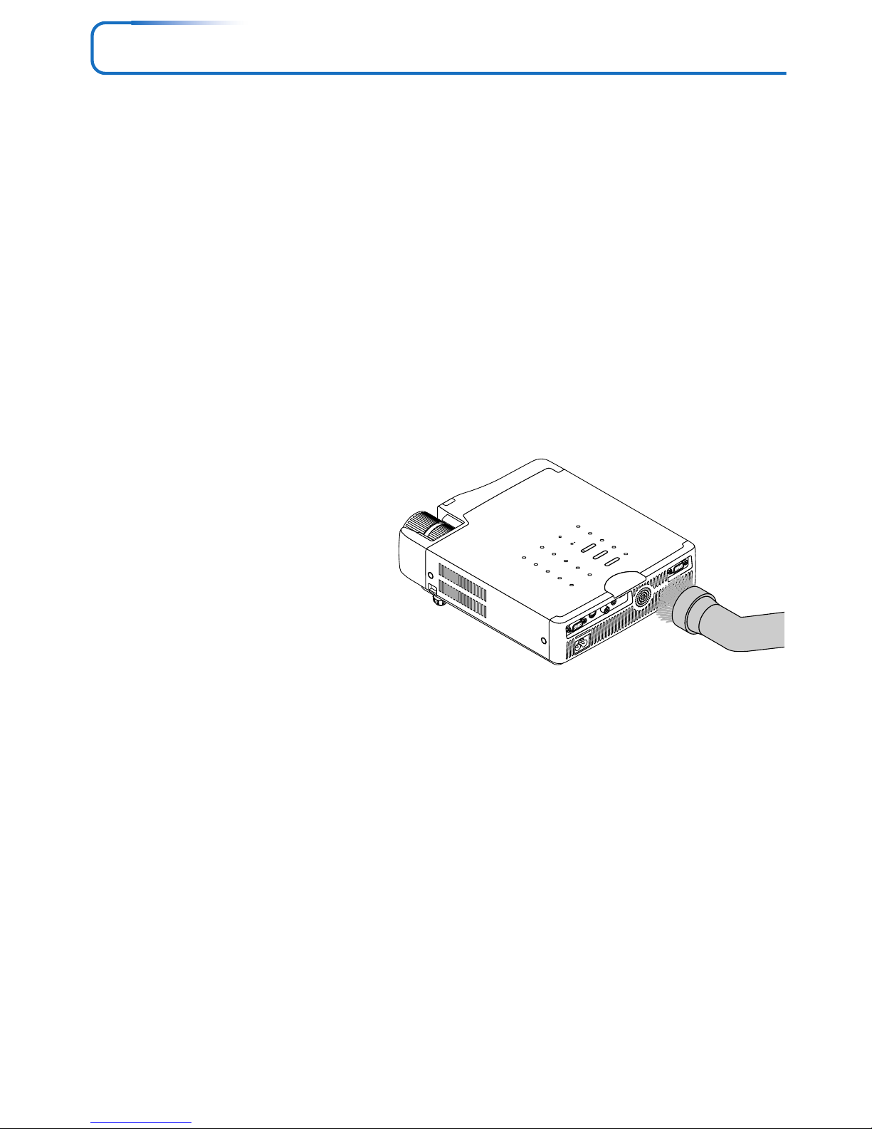
E-63
Cleaning
• Be certain to disconnect the power plug from the power outlet before cleaning.
• Do not spray or otherwise expose the projector, lens, or screen to volatile substances such as insecticides. Do not leave rubber
or vinyl products in contact with the projector for long periods. Doing so could cause them to undergo qualitative changes or the
coatings may peel, etc.
Cleaning a Soiled Projector Main Unit
• Wipe with a lint-free, soft, dry cloth.
When very dirty, wipe with a cloth that has been moistened with a diluted neutral detergent, then finish with a dry cloth. If a
chemically-treated cloth is going to be used, please follow any written warnings.
• Do not wipe with thinner, benzene, or other solvents. Doing so could cause them to undergo qualitative changes or the coatings
may peel, etc.
• When removing the dust of the outflow and intake holes, use the brush attachment on a vacuum cleaner to clean out the dust.
Avoid using the vacuum directly without attaching the adapter as well as the use of a nozzle adapter.
• Do not scratch or otherwise hit the projector body with your nails or other hard object, since this will cause scratches.
Dirty Lens
• Clean using the same method you would use to clean a camera lens: Use a commercial blower for camera use or cleaning
paper for eye glasses. Be careful not to scratch the lens at this time.
Dust of the Intake and Outflow Holes
Dust that collects in the intake and outflow holes will obstruct the ventilation and cause the internal temperature to rise which
could cause damage. Clean this area carefully. As a guideline, clean at least every 100 hours of usage.
• Switch off the power, check that the STANDBY indicator has changed to a steadily lit amber, then
unplug the power cable.
• Clean out the holes from the outside using a
vacuum cleaner. Use the brush adapter of the
vacuum cleaner to do this. Avoid using the vacuum
directly without attaching the adapter as well as the
use of a nozzle adapter.
Cleaning the Inside of the Projector
Cleaning of the inside of the projector is required about once a year. Failure to clean over a long period while dust has collected
inside the projector could cause a fire or breakdown. Do not clean the inside of the projector by yourself. Please be sure to contact
your dealer.
STANDBY
STATUS
S
T
A
N
D
B
Y
A
U
T
O
S
O
U
R
C
E
RGB
S VIDEO
VIDEO
AUDIO
MOUSE
PC CONTROL
Page 64
E-64
Replacing the Lamp Cartridge
• The lamp that is used as a light source in the projector has a limited service life. The rated service life of the lamp is
about 2000 hours (when used in normal mode only). This could be shortened depending on conditions of use and
other factors.
Note that lamp life will be extended when the projector is often used in Eco mode. (The rated service life of the lamp
means the average value of lamp life for lamps that have been manufactured over a long period, and it is derived from
test conditions at this company.)
• When the life of the lamp is exceeded, the STATUS indicator lights a steady red and the message [Replace the Lamp
Cartridge] is displayed on the screen. When this occurs, it is time to replace the lamp cartridge. Please make the
replacement following the procedure below.
• If the projector is used another 100 hours after the lamp’s service life is reached, the power is set to the standby mode
and no longer turns on.
• Contact a store that sells the U5-632h/U5-732h/U5-532h/U5-512h for a replacement lamp. Indicate you need a U5-201
replacement lamp for the U5-632h/U5-732h/U5-532h/U5-512h (order code 28-030).
CAUTION
• Replacement of the lamp cartridge is performed after switching off the power, waiting for the cooling fan to stop,
disconnecting the power plug from the power outlet, and then leaving the projector for about 60 minutes before
replacement is started. Replacement of the lamp cartridge during operation or immediately after operation stops will
cause burns because of the high temperature.
• Do not remove any screws other than those specified.
• Do not touch the lamp with bare hands. Doing so could shorten the life of the lamp.
• If lamp has reached the end of its usable life, the lamp bulb may shatter. When this happens, an explosive sound can
be heard and pieces of glass may be scattered in the lamp cartridge. Do not touch them as the pieces of glass may
cause injury. If this happens, contact your dealer or the store the projector was purchased.
Page 65
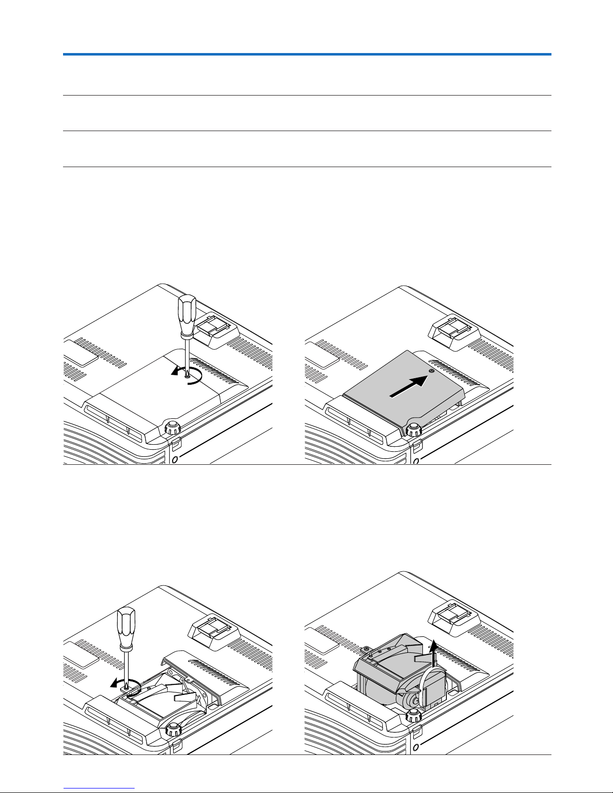
E-65
Replacing the Lamp Cartridge
Preparations: Turning the projector upside-down on top of a soft cloth, etc., so that it does not get scratched makes it easier to
replace the lamp cartridge. Turn the projector right-side up after replacing the lamp cartridge.
1
Unplug the power cord.
2
Turn the projector upside-down.
3
Remove the lamp cover.
(1) Turn the lamp cover’s set screw counterclockwise and
loosen until the screw turns freely. (The screw does
not come off.)
(2) Open the lamp cover a little, then pull it in the direc-
tion of the arrow and remove it.
4
Remove the lamp cartridge.
(1) Turn the lamp cartridge’s screw counterclockwise and
loosen them until the screw turn freely. (The screw
do not come off.)
(2) Grasp the lamp cartridge’s handle and pull upward
to remove the lamp cartridge.
Page 66
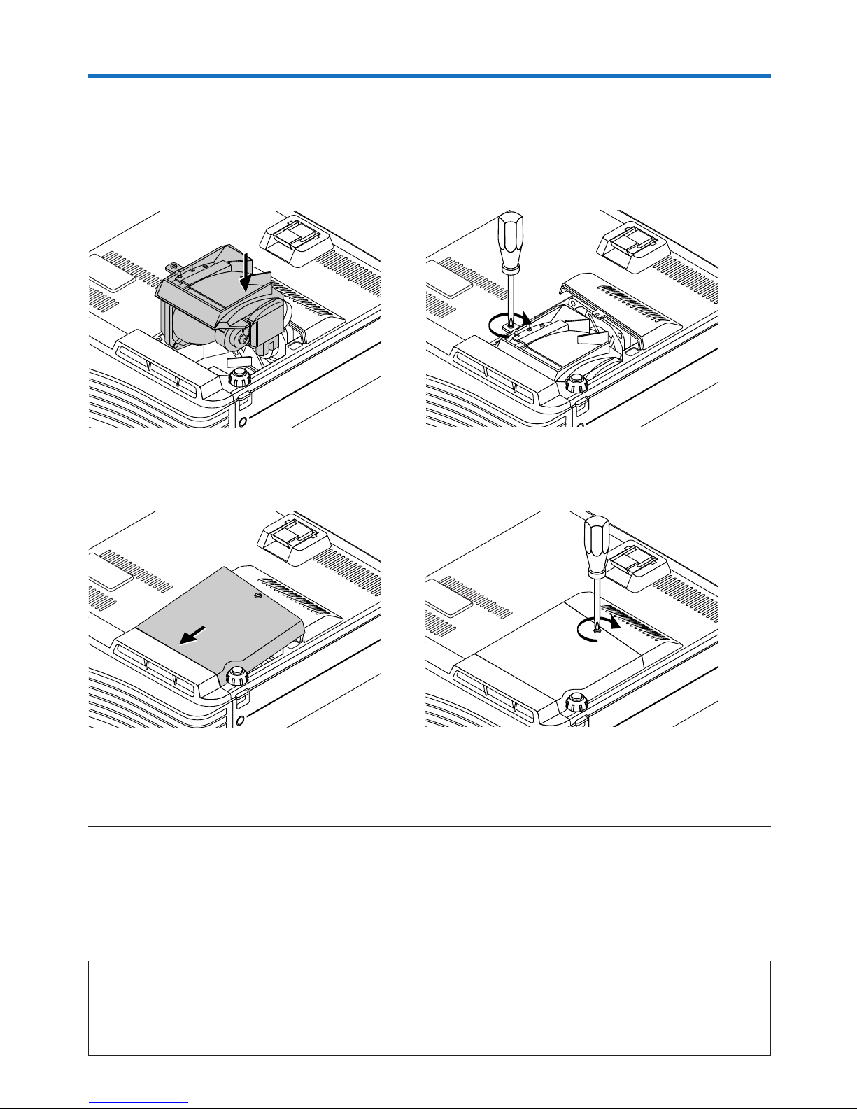
E-66
Replacing the Lamp Cartridge
5
Mount the new lamp cartridge.
(1) Push the lamp cartridge in slowly.
(Line it up with the screw holes in the projector.)
6
Mount the lamp cover.
(1) Set the tip of the lamp cover in place, then close the
lamp cover.
7
Reset the Lamp Timer.
Connect the power cable, switch on the power, and then reset.
Select [Info.] → [Lamp Timer Reset] on the menu and press the ENTER button. There is a change to the initialization
verification display. Press the ENTER button again. See “Lamp Timer Reset” on Page E-59.
Note:
After reaching the lamp service life, if the lamp is used for more than another 100 hours, it will not be possible to switch on the power. Should
this happen, while the projector is in the standby mode, simultaneously holding down the projector’s SOURCE button and AUTO button for
more than 5 seconds will clear the lamp timer. Checking that the STATUS indicator is out will show that the lamp timer has been cleared.
Contact a store that sells the U5-632h/U5-732h/U5-532h/U5-512h for a replacement lamp. Indicate you need a U5-201 replacement lamp for
the U5-632h/U5-732h/U5-532h/U5-512h (order code 28-030).
(2) Turn the lamp cartridge screw clockwise to tighten
them.
(2) Turn the lamp cover’s screw clockwise to tighten it.
Page 67

E-67
Specifications
Model U5-632h
Optical
Method of projection : DLP™ (single DLP™ chip)
DLP™ chip 0.7 inches 1024⳯768 dots
Lamp 200 W high pressure mercury lamp
Projection lens : Manual zoom (⳯1.2), Manual focus F = 2.6 – 2.9, f = 18.4 – 22.1 mm (f = 0.72 – 0.87 inch)
Image size Minimum: 38.4 inch (at projection distance of 1.2m(3.9 feet) telephoto)
Maximum: 300 inch (at projection distance of 8.0m(26.2 feet) wide)
Light Output Standard mode: 2300 lumens (in the “Dynamic” mode)
B/W mode: 3000 lumens (in the “Dynamic” mode)
Contrast Ratio 2000:1 (Full on/off)
Electrical
Inputs Video (NTSC3.58/NTSC4.43/PAL/PAL-N/PAL-M/PAL60/SECAM/YCbCr(NTSC, PAL)/
YPbPr(480p, 576p, 1080i, 720p)): (automatic or manual switching)
RGB (Horizontal: 15 to 80 kHz, Vertical: 50 to 85 Hz)
Color Reproduction Full color (16,770,000 colors)
Resolution VGA (640⳯480) expansion/true, S-VGA (800⳯600) expansion/true
XGA (1024⳯768) true, S-XGA (1280⳯1024) compression
Input Current 2.8/1.4 A
Power Requirement 100 – 120/220 – 240 V AC, 50/60 Hz
Power Consumption 280 watts (250 watts in eco mode)
Mechanical
Dimensions Excluding Stand 216 mm (W)⳯60 mm (H)⳯252 mm (D) (not including protrusion)
8.5 in.(W)⳯2.4 in.(H)⳯10.3 in.(D) (not including protrusion)
Weight Approximately 2.0 kg / 4.4 lbs
Operational Temperatures Data projector: 5° to 35°C (41° to 95°F), 30 to 85% humidity
• Specifications and design are subject to change without notice.
Page 68

E-68
Model U5-732h
Optical
Method of projection : DLP™ (single DLP™ chip)
DLP™ chip 0.7 inches 1024⳯768 dots
Lamp 200 W high pressure mercury lamp
Projection lens : Manual zoom (⳯1.2), Manual focus F = 2.4 – 2.6, f = 26.5 – 31.8 mm (f = 1.04 – 1.25 inch)
Image size Minimum: 27 inch (at projection distance of 1.2 m (3.9 feet) telephoto)
Maximum: 300 inch (at projection distance of 11.5 m (37.7 feet) wide)
Light Output 2500 lumens (in the “Dynamic” mode)
Contrast Ratio 2000:1 (Full on/off)
Electrical
Inputs Video (NTSC3.58/NTSC4.43/PAL/PAL-N/PAL-M/PAL60/SECAM/YCbCr(NTSC, PAL)/
YPbPr(480p, 576p, 1080i, 720p)): (automatic or manual switching)
RGB (Horizontal: 15 to 80 kHz, Vertical: 50 to 85 Hz)
Color Reproduction Full color (16,770,000 colors)
Resolution VGA (640⳯480) expansion/true, S-VGA (800⳯600) expansion/true
XGA (1024⳯768) true, S-XGA (1280⳯1024) compression
Input Current 2.8/1.4 A
Power Requirement 100 – 120/220 – 240 V AC, 50/60 Hz
Power Consumption 280 watts (250 watts in eco mode)
Mechanical
Dimensions Excluding Stand 216 mm (W)⳯60 mm (H)⳯260 mm (D) (not including protrusion)
8.5 in.(W)⳯2.4 in.(H)⳯10.2 in.(D) (not including protrusion)
Weight Approximately 2.1 kg / 4.6 lbs
Operational Temperatures Data projector: 5° to 35°C (41° to 95°F), 30 to 85% humidity
• Specifications and design are subject to change without notice.
Specifications
Page 69

E-69
Model U5-532h
Optical
Method of projection : DLP™ (single DLP™ chip)
DLP™ chip 0.55 inches 1024⳯768 dots
Lamp 200 W high pressure mercury lamp
Projection lens : Manual zoom (⳯1.2), Manual focus F = 2.6 – 2.9, f = 20.0 – 24.0 mm (f = 0.79 – 0.94 inch)
Image size Minimum: 27.6 inch (at projection distance of 1.2m(3.9 feet) telephoto)
Maximum: 300 inch (at projection distance of 11.1m(36.4 feet) wide)
Light Output Standard mode: 2000 lumens (in the “Dynamic” mode)
B/W mode: 3000 lumens (in the “Dynamic” mode)
Contrast Ratio 2000:1 (Full on/off)
Electrical
Inputs Video (NTSC3.58/NTSC4.43/PAL/PAL-N/PAL-M/PAL60/SECAM/YCbCr(NTSC, PAL)/
YPbPr(480p, 576p, 1080i, 720p)): (automatic or manual switching)
RGB (Horizontal: 15 to 80 kHz, Vertical: 50 to 85 Hz)
Color Reproduction Full color (16,770,000 colors)
Resolution VGA (640⳯480) expansion/true, S-VGA (800⳯600) expansion/true
XGA (1024⳯768) true, S-XGA (1280⳯1024) compression
Input Current 2.8/1.4 A
Power Requirement 100 – 120/220 – 240 V AC, 50/60 Hz
Power Consumption 280 watts (250 watts in eco mode)
Mechanical
Dimensions Excluding Stand 216 mm (W)⳯60 mm (H)⳯240 mm (D) (not including protrusion)
8.5 in.(W)⳯2.4 in.(H)⳯10.3 in.(D) (not including protrusion)
Weight Approximately 2.0 kg / 4.4 lbs
Operational Temperatures Data projector: 5° to 35°C (41° to 95°F), 30 to 85% humidity
• Specifications and design are subject to change without notice.
Specifications
Page 70

E-70
Model U5-512h
Optical
Method of projection : DLP™ (single DLP™ chip)
DLP™ chip 0.55 inches 800⳯600 dots
Lamp 200 W high pressure mercury lamp
Projection lens : Manual zoom (⳯1.2), Manual focus F = 2.6 – 2.9, f = 20.0 – 24.0 mm (f = 0.79 – 0.94 inch)
Image size Minimum: 27.6 inch (at projection distance of 1.2m(3.9 feet) telephoto)
Maximum: 300 inch (at projection distance of 11.1m(36.4 feet) wide)
Light Output Standard mode: 2000 lumens (in the “Dynamic” mode)
Contrast Ratio 2000:1 (Full on/off)
Electrical
Inputs Video (NTSC3.58/NTSC4.43/PAL/PAL-N/PAL-M/PAL60/SECAM/YCbCr(NTSC, PAL)/
YPbPr(480p, 576p, 1080i, 720p)): (automatic or manual switching)
RGB (Horizontal: 15 to 80 kHz, Vertical: 50 to 85 Hz)
Color Reproduction Full color (16,770,000 colors)
Resolution VGA (640⳯480) expansion/true, S-VGA (800⳯600) true
XGA (1024⳯768) compression
Input Current 2.8/1.4 A
Power Requirement 100 – 120/220 – 240 V AC, 50/60 Hz
Power Consumption 280 watts (250 watts in eco mode)
Mechanical
Dimensions Excluding Stand 216 mm (W)⳯60 mm (H)⳯240 mm (D) (not including protrusion)
8.5 in.(W)⳯2.4 in.(H)⳯10.3 in.(D) (not including protrusion)
Weight Approximately 1.9 kg / 4.2 lbs
Operational Temperatures Data projector: 5° to 35°C (41° to 95°F), 30 to 85% humidity
• Specifications and design are subject to change without notice.
Specifications
Page 71
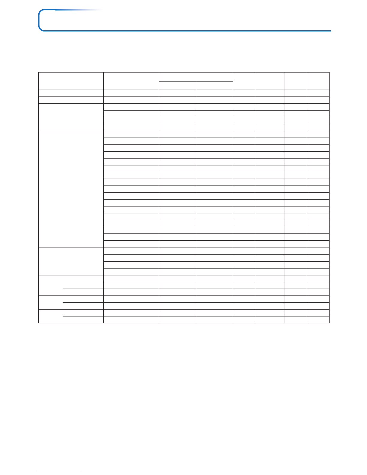
E-71
Table of Supported Frequency
The projector automatically identifies the signal input from the computer and selects the optimum resolution as shown on the table
below.
Manual adjustments may be required for some input signals. See “Picture Adj. / Fine Picture / H Position / V Position” on page
E-47, 48.
VIDEO(NTSC)
VIDEO(PAL/SECAM)
PC/AT
VESA
Apple Macintosh
HDTV (1080i)
(720p)
EDTV (576p)
(480p)
SDTV (576i)
(480i)
ⳮ
ⳮ
640 ⳯ 350
640 ⳯ 400
720 ⳯ 350
720 ⳯ 400
640 ⳯ 350
640 ⳯ 400
720 ⳯ 400
640 ⳯ 480
640 ⳯ 480
640 ⳯ 480
640 ⳯ 480
800 ⳯ 600
800 ⳯ 600
800 ⳯ 600
800 ⳯ 600
800 ⳯ 600
1024 ⳯ 768
1024 ⳯ 768
1024 ⳯ 768
1024 ⳯ 768
1280 ⳯ 1024
640 ⳯ 480
823 ⳯ 624
1024 ⳯ 768
1152 ⳯ 870
1920 ⳯ 1080
1920 ⳯ 1080
1280 ⳯ 720
720 ⳯ 576
720 ⳯ 480
720 ⳯ 576
720 ⳯ 480
15.734
15.625
31.5
31.5
31.5
31.5
37.9
37.9
37.9
31.5
37.9
37.5
43.3
35.2
37.9
46.9
48.1
53.7
48.4
56.5
60.0
68.7
64.0
35.0
49.7
60.2
68.7
33.8
28.1
45.0
31.3
31.5
31.3
31.5
60.0
50.0
70.1
70.1
70.0
70.0
85.1
85.1
85.0
60.0
72.8
75.0
85.0
56.3
60.3
75.0
72.2
85.1
60.0
70.1
75.0
85.0
60.0
66.7
74.5
74.9
75.1
60.0
50.0
60.0
50.0
60.0
50.0
60.0
嘷
嘷
ⳮ
ⳮ
ⳮ
ⳮ
ⳮ
ⳮ
ⳮ
ⳮ
ⳮ
ⳮ
ⳮ
ⳮ
ⳮ
ⳮ
ⳮ
ⳮ
ⳮ
ⳮ
ⳮ
ⳮ
ⳮ
ⳮ
ⳮ
ⳮ
ⳮ
ⳮ
ⳮ
ⳮ
ⳮ
ⳮ
ⳮ
ⳮ
嘷
嘷
ⳮ
ⳮ
ⳮ
ⳮ
ⳮ
ⳮ
ⳮ
ⳮ
ⳮ
ⳮ
ⳮ
ⳮ
ⳮ
ⳮ
ⳮ
ⳮ
ⳮ
ⳮ
ⳮ
ⳮ
ⳮ
ⳮ
ⳮ
ⳮ
ⳮ
嘷
嘷
嘷
嘷
嘷
嘷
嘷
ⳮ
ⳮ
ⳮ
ⳮ
ⳮ
ⳮ
ⳮ
ⳮ
ⳮ
ⳮ
ⳮ
ⳮ
ⳮ
ⳮ
ⳮ
ⳮ
ⳮ
ⳮ
ⳮ
ⳮ
ⳮ
ⳮ
ⳮ
ⳮ
ⳮ
ⳮ
ⳮ
ⳮ
ⳮ
ⳮ
ⳮ
ⳮ
ⳮ
ⳮ
ⳮ
ⳮ
嘷
嘷
嘷
嘷
嘷
嘷
嘷
嘷
嘷
嘷
嘷
嘷
嘷
嘷
嘷
嘷
嘷
嘷
嘷
嘷
嘷
嘷
嘷
嘷
嘷
ⳮ
ⳮ
ⳮ
ⳮ
ⳮ
ⳮ
ⳮ
Signal
Resolution Video
Frequency
Horizonral (kHz)
Vertical (Hz)
Component
Digital Analog
嘷 : Supported frequency
ⳮ : Not supported frequency
* The model name for XGA is U5-632h/U5-732h/U5-532h and SVGA U5-512h.
* The projector does not support the ADC connector on Apple Macintosh.
U5-632h/U5-732h/U5-532h
The display resolution is 1024⳯768 dots. When displaying a signal with resolutions other than 1024⳯768 dots such as 1280⳯1024,
sizes of characters or lines may be uneven.
U5-512h
The display resolution is 800⳯600 dots. When displaying a signal with resolutions other than 800⳯600 dots such as 1024⳯768,
sizes of characters or lines may be uneven.
Page 72
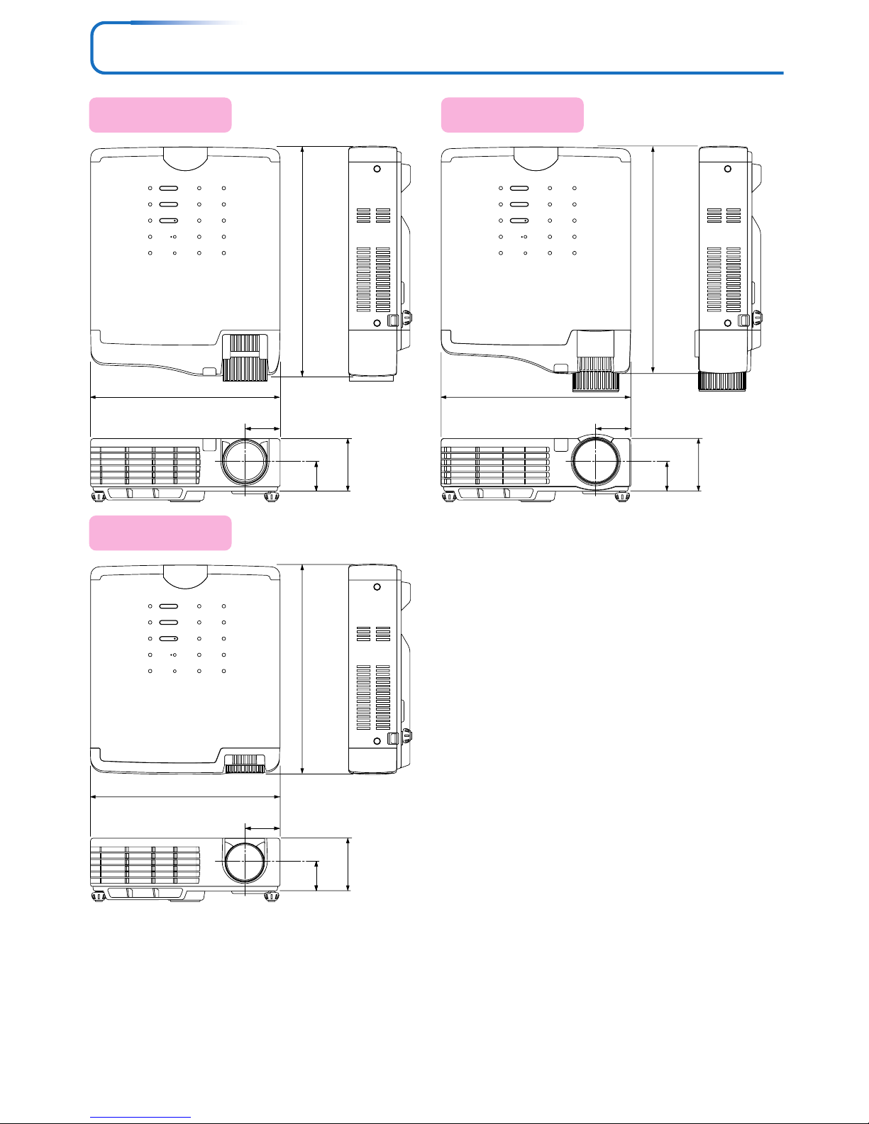
E-72
STANDBY
STATUS
STANDBY
AUTO
SOURCE
216 (8.5)
60 (2.4)
252 (9.9)
STANDBY
STATUS
STANDBY
AUTO
SOURCE
216 (8.5)
60 (2.4)
240 (9.5)
STANDBY
STATUS
STANDBY
AUTO
SOURCE
216 (8.5)
60 (2.4)
260 (10.2)
32.5
(1.3)
34
(1.3)
40
(1.6)
40
(1.6)
40
(1.6)
34
(1.3)
Cabinet Dimensions
Applicable Projector:
U5-532h/U5-512h
Applicable Projector:
U5-632h
Applicable Projector:
U5-732h
Unit: mm (inch)
Page 73
2005
 Loading...