

Plus U3W User Manual
DATA PROJECTOR
U3-1100/U3-810
USER’S MANUAL
English
Applicable Models: U3-1100WZ, U3-1100W, U3-1100SF
U3-810WZ, U3-810W, U3-810SF
P
O
P
W
O
W
E
E
R
R
O
U
R
C
S
E
T
A
T
U
S
A
U
T
OS
PLUS
B / W
COLOR
O
P
EN
Digital Light Processing, DLP, Digital Micromirror Device and DMD are all trademarks of
IMPORTANT
Te xas Instruments.
Windows 98, Windows 95, and Windows 3.1 are registered trademarks in the United States
and other countries of Microsoft Corporation.
IBM is a registered trademark of International Business Machines Corporation.
Macintosh and MAC are trademarks of Apple Computer Inc.
Other names of companies and products mentioned are trademarks and registered trademarks of the respective companies.
TM
, ® and © marks are not used in this document.
PLUS Industrial Corporation is certified to ISO 9001.
Certificate No. Q1001219118017.
Otowa Head Office and PLUSLAND of PLUS Corporation
and PLUS Industrial Corporation are certified to ISO 14001.
Certificate No. NQE-9809008A.
* PLUS Vision Corp. is certified to ISO 14001 as a member of the
PLUS group.
IMPORTANT SAFETY INFORMATION
Precautions
Please read this manual carefully before using your PLUS U3-1100WZ, U3-1100W, U3-1100SF, U3-810WZ, U3-810W, U3-810SF
Data Projector and keep the manual handy for future reference.
CAUTION
TO PREVENT SHOCK, DO NOT OPEN THE CABINET. NO USER-SERVICEABLE PARTS INSIDE.
REFER SERVICING TO QUALIFIED PLUS SERVICE PERSONNEL.
This symbol warns the user that uninsulated voltage within the unit may have sufficient
magnitude to cause electric shock. Therefore, it is dangerous to make any kind of contact with
any part inside of this unit.
This symbol alerts the user that important literature concerning the operation and maintenance of this unit has been included. Therefore, it should be read carefully in order to avoid
any problems.
The above cautions are given on the bottom of the product.
WARNING
TO PREVENT FIRE OR SHOCK, DO NOT EXPOSE THIS UNIT TO RAIN OR MOISTURE. DO
NOT USE THIS UNIT’S GROUNDED PLUG
WITH AN EXTENSION CORD OR IN AN OUTLET UNLESS ALL THREE PRONGS CAN BE
FULLY INSERTED. DO NOT OPEN THE CABINET. THERE ARE HIGH-VOLTAGE COMPONENTS INSIDE. ALL SERVICING MUST BE
DONE BY QUALIFIED PLUS SERVICE PERSONNEL.
WARNING
This is a class A product. In a domestic environment this
product may cause radio interference in which case the user
may be required to take adequate measures.
RF Interference
WARNING
The Federal Communications Commission does not allow
any modifications or changes to the unit EXCEPT those
specified by PLUS Technologies in this manual. Failure to
comply with this government regulation could void your
right to operate this equipment.
This equipment has been tested and found to comply with
the limits for a Class A digital device, pursuant to Part 15 of
the FCC Rules. These limits are designed to provide
reasonable protection against harmful interference when
the equipment is operated in a commercial environment.
This equipment generates, uses, and can radiate radio
frequency energy and, if not installed and used in
accordance with the instruction manual, may cause
harmful interference to radio communications. Operation
of this equipment in a residential area is likely to cause
harmful interference in which case the user will be required
to correct the interference at his own expense.
Important Safeguards
These safety instructions are to ensure the long life of the unit and to prevent fire and shock. Please read them carefully and heed all warnings.
Installation
•For best results, use the unit in a darkened room.
• Place the unit on a flat, level surface in a dry area away from dust
and moisture.
• Do not place the unit in direct sunlight, near heaters or heat
radiating appliances.
• Exposure to direct sunlight, smoke or steam can harm internal
components.
• Handle the unit carefully. Dropping or jarring can damage internal components.
•Do not place heavy objects on top of the unit.
Power Supply
• The unit is designed to operate on a power supply of 100 to 120
and 220 to 240 V 50/60 Hz AC. Ensure that your power supply
fits these requirements before attempting to use the unit.
•For PLUGGABLE EQUIPMENT, the socket-outlet shall be
installed near the equipment and shall be accessible.
• Handle the power cable carefully and avoid excessive bending. A
damaged cord can cause electric shock or fire.
•Disconnect the power cable (mains lead) from the power outlet
after using the unit.
Before disconnecting the power cable, make sure that the
POWER indicator lights in amber (not blinking or in green).
E – 2

Table of contents
Cleaning
• Disconnect the power cable (mains lead) from the unit.
• Clean the cabinet of the unit periodically with a damp cloth. If
heavily soiled, use a mild detergent. Never use strong detergents
or solvents such as alcohol or thinner.
• Use a blower or lens paper to clean the lens, and be careful not to
scratch or mar the lens.
• Clean the ventilation slots and speaker grills on the unit
periodically using a vacuum cleaner. If accumulated dust blocks
the ventilation slots, the unit will overheat, which may cause the
unit to malfunction.
Use a soft brush attachment when using the vacuum cleaner. Do
not use a hard attachment, such as a crevice tool, to prevent the
damage to the unit.
Lamp Replacement
• Be sure to replace the lamp when the Status indicator comes on.
If you continue to use the lamp after 1000 hours of usage, the
lamp will turn off.
Fire and Shock Precautions
• Ensure that there is sufficient ventilation and that vents are
unobstructed to prevent the buildup of heat inside the unit. Allow
at least 10 cm (3 inches) of space between the unit and walls.
•Prevent foreign objects such as paper clips and bits of paper from
falling into the unit. Do not attempt to retrieve any objects that
fell into the unit. Do not insert any metal objects such as a wire or
screwdriver into the unit. If something should fall into the unit,
immediately disconnect the power cable from the unit and have
the object removed by a qualified PLUS service person.
• Do not place any liquids on top of the unit.
• Do not look into the lens while the unit is on. Serious damage
to your eyes could result.
Carrying around
When carrying the unit around, please use the carrying case that
comes with it and, to protect the lens from scratches, always shut
the sliding lens cap. Also, do not subject the unit to strong
mechanical shock.
IMPORTANT SAFETY INFORMATION ................................... 2
Table of contents ........................................................................ 3A
Basic information and preparations ........ 4
Features ......................................................................................... 4
Checking the supplied accessories ............................................... 4
Preparing the remote control ........................................................ 5
Parts and controls .......................................................................... 6
Installation ..................................................................................... 9
Connections ............................................ 10
Connecting video equipment ...................................................... 10
Connecting Video Equipment With Component Video Signal
(YCbCr) Output .......................................................................... 11
Connecting a PC or Macintosh ................................................... 12
Operation ................................................. 14
Using the unit .............................................................................. 14
Using the Remote Control (Input Selection) .............................. 16
Using the Remote Control as the PC Mouse .............................. 17
Various functions while using the unit ....................................... 18
Use as a High-Brightness Monochrome Projector .................. 19B
Menu operation....................................... 20
Menu Structure ............................................................................ 20
Adjusting the picture elements ................................................... 22
Adjusting the projected image from the computer .................... 23
Manual Adjustment of Personal Computer Images ................... 24
Resetting ...................................................................................... 25
Resetting the Lamp Hours of Usage ........................................... 25
Setting Narrow Images (Advanced Menu) ................................. 26
Setting in Accordance With Image Contents.............................. 27
Initial Settings ............................................................................. 28
Setting the Menu ......................................................................... 30
Others ....................................................... 31
Troubleshooting .......................................................................... 31
When the STATUS indicator lights or flashes ........................... 32
Replacing the lamp cartridge ...................................................... 33
Specifications .............................................................................. 34
E – 3A
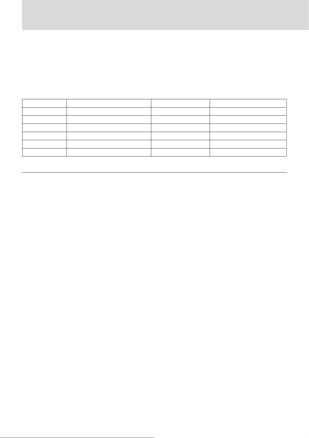
This User's Manual covers the following models: U3-1100WZ, U3-1100W, U3-1100SF,
U3-810WZ, U3-810W, and U3-810SF.
Depending on the projector that you purchased, the resolution may differ from another projector and some models
may not have an optical zoom function nor a high-brightness monochrome function. This manual provides a description of the U3-1100WZ (with a full complement of functions).
Please check the table below regarding the resolution and availability of functions for your projector.
Model Resolution (Full screen display)
U3-1100WZ 1024⳯768 (XGA) 嘷嘷
U3-1100W 1024⳯768 (XGA) ⳯嘷
U3-1100SF 1024⳯768 (XGA) ⳯⳯
U3-810WZ 800⳯600 (S-VGA) 嘷嘷
U3-810W 800⳯600 (S-VGA) ⳯嘷
U3-810SF 800⳯600 (S-VGA) ⳯⳯
Optical Zoom Function
High-Brightness Monochrome Function
嘷: With function ⳯: Without function
E – 3B
Basic information and preparations
Checking the
Features
Congratulations On Your Purchase Of The U31100WZ, U3-1100W, U3-1100SF, U3-810WZ, U3810W, U3-810SF Data Projector
The U3-1100WZ, U3-1100W, U3-1100SF, U3-810WZ, U3-810W, U3810SF is one of the most spectacular data projectors available today. The
unit enables you to project precise images up to 200 inches across (measured diagonally) from your PC or Macintosh computer (desktop or notebook), VCR, document camera, laser disc player, DVD player, etc.
The unit can be placed on a tabletop or cart. The unit can also be used to
project images from behind the screen.*
* Consult your dealer for more information.
The other main features you’ll enjoy
• Compatible with following various color systems:
– NTSC (U.S. and Canada standard)
–PAL (Western Europe standard)
– SECAM (France and Eastern Europe standard)
– NTSC4.43 (Middle East standard)
• (U3-1100WZ, U3-1100W, U3-1100SF)
Superior brightness of 1000 ANSI lumens (In color mode) /2200
ANSI lumens (In B/W mode), small size, and weighing only about 1.5
kilograms/3.3 lbs.
(U3-810WZ, U3-810W, U3-810SF)
Superior brightness of 1000 ANSI lumens: In color mode/2200 ANSI
lumens: In monochrome mode, small size, and weighing only about
1.5 kilograms/3.3 lbs.
Using TI’s Digital Mirror Device (DMD) and our own optical design we
have developed a geometric effect that increases the light usage efficiency. By increasing the light usage efficiency we can better reproduce
the three basic colors (RGB) required for color reproduction on a single
DMD. This means superior brightness, smaller size, and lighter weight.
• Sharp, clear images
There is no RGB color separation, and the spaces between the individual
pixels are not noticeable. That means sharp and clear reproduction of
small characters and figures. Take a closer look and notice the difference
in quality!
• Outstanding sharp, clear, 3D like images with vivid colors when
reproducing DVD video and other high picture-quality data/video
sources
Accurate gray scale reproduction makes for more natural image displays.
DVD and other high quality image sources bring out the true image
display quality of the unit.
• Screen not distorted to a trapezoid (keystoning) when projecting to
the height of the line of vision
Because the projection position is already set to the height of the line of
vision, there is no keystoning effect.
Even when projecting above or under the height of the line of vision,
image distortion (if any) can be adjusted using the keystone correction
function.
• (U3-1100WZ, U3-1100W, U3-1100SF)
Fully compatible with true XGA; support for SXGA using advanced
intelligent compression technology
The advanced intelligent compression technology enables these projectors
to present clear compression SXGA images without any line omission.
(U3-810WZ, U3-810W, U3-810SF)
Fully compatible with true S-VGA; support for XGA using advanced intelligent compression technology
The advanced intelligent compression technology enables it to present clear
compression XGA images without any line omission.
•A remote control that can operate the PC or Macintosh
The supplied remote control both operates the unit and acts as a wireless
mouse control to operate the PC or Macintosh connected to the unit.
• The compact and easy to carry cabinet with its contemporary design
complements any office, board room, or auditorium.
• The Industry's First B/W Mode that Can Be Switched to Double
Brightness
When projecting data that is largely black and white such as documents
and spreadsheets, setting the top panel switch to B/W Mode will allow
double the brightness as compared to the color setting. Never before has
this function been incorporated in a projector, making the most of the
features of the high contrast ratio DLP system projector.
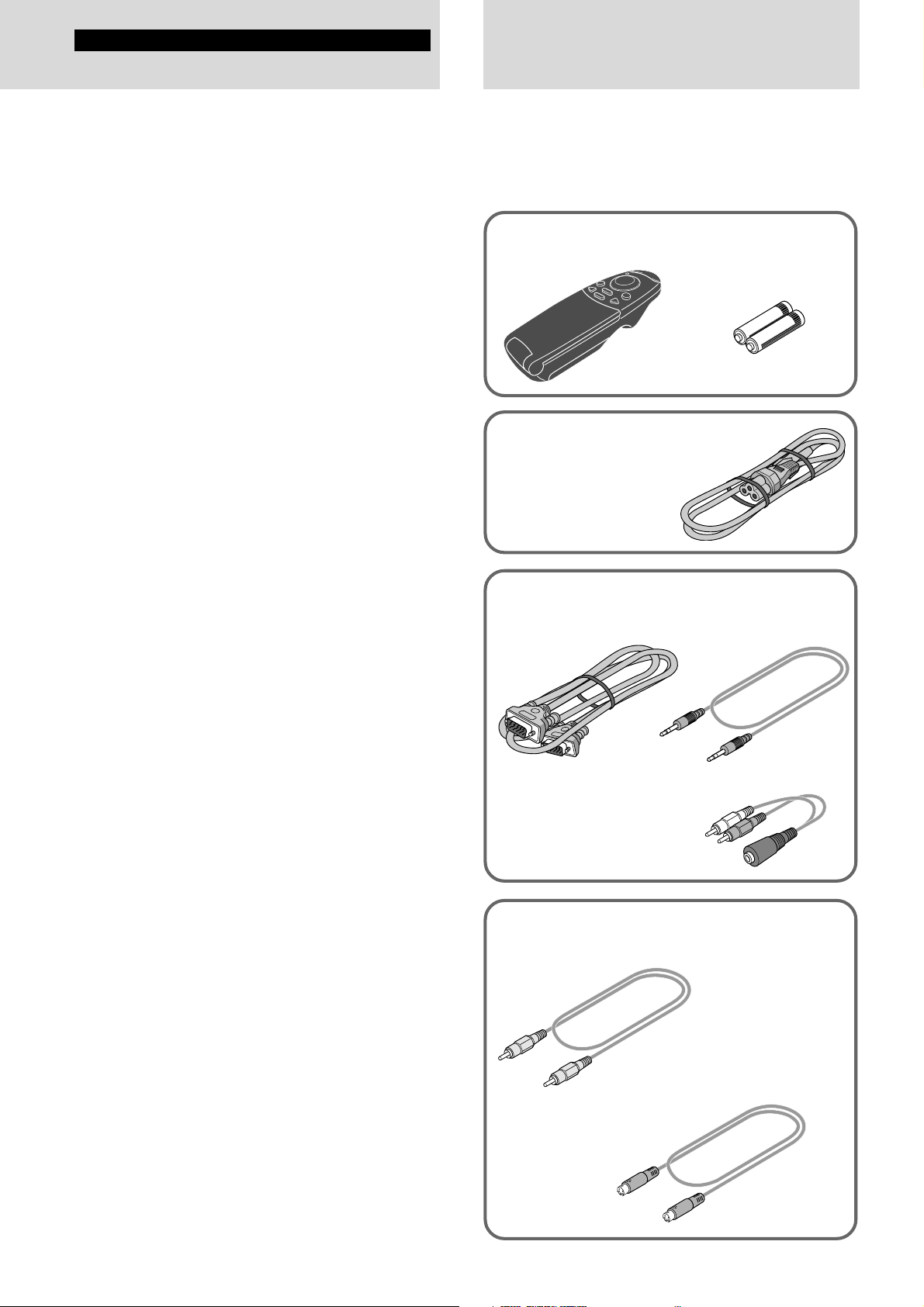
supplied accessories
Make sure your box contains everything listed below. If any
pieces are missing, contact your dealer.
Please save the original box and packing materials in case
you ever need to ship the unit.
The number of accessories is indicated in brackets.
For remote control
Remote control [1] Batteries (size AAA) [2]
Power cable (mains lead)
(1.8 m/5.9 ft.) [1]
The shape of the plug varies
depending on the region where
the unit is purchased.
For computer connection
RGB cable
(1 m/3.3 ft.) [1]
No. 770708000
Audio adaptor
(mini-jack pin conversion,
0.15 m/0.5 ft) [1]
No. 770704000
For video equipment connection
Video cable
(1 m/3.3 ft.) [1]
No. 770703000
S-video cable
(1 m/3.3 ft.) [1]
No. 770709000
Audio cable
(1 m/3.3 ft.) [1]
No. 770710000
E – 4
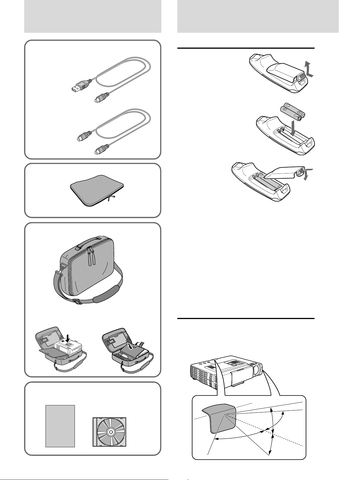
When using the remote control as computer
mouse
USB mouse cable (1 m/3.3 ft.) [1]
[for IBM / Macintosh]
No. 770707000
PS/2 mouse cable (1 m/3.3 ft.) [1]
[for IBM PS/2]
No. 770706000
Soft pouch [1]
Preparing the remote control
Inserting the batteries
1 Press firmly and slide
the battery cover off.
2 Insert the two supplied
batteries (size AAA).
Ensure that the
polarities (+ and –) of
the batteries are aligned
correctly.
3 Slide the cover
back until it
snaps into
place.
Carrying case [1]
How to use the carrying case
Packing the unit
Packing the accessories
CAUTION
Danger of explosion if battery is incorrectly replaced. Replace only
with the same or equivalent type recommended by the manufacturer.
Dispose of used batteries according to the manufacturer’s instructions.
Notes
• If the remote control gets wet, wipe it dry immediately.
•Avoid excessive heat and humidity.
• If you will not be using the remote control for a long time, remove the
batteries.
• Do not mix new and old or different types of batteries.
• There are operations that can only be carried out by remote control.
Handle the remote control carefully.
Remote control effective range
The remote sensors are located on the front and back of the unit.
The controllable range is 50 degrees horizontally and 30 degrees
vertically relative to a line that is at a right angle to the remote
sensor. And the distance between the point of the remote control
and remote sensor must be shorter than four meters (13 feet).
USER’S MANUAL
(Simplified Edition) [1]
USER’S MANUAL
(CD-ROM Edition) [1]
E – 5
50˚
30˚
30˚
50˚
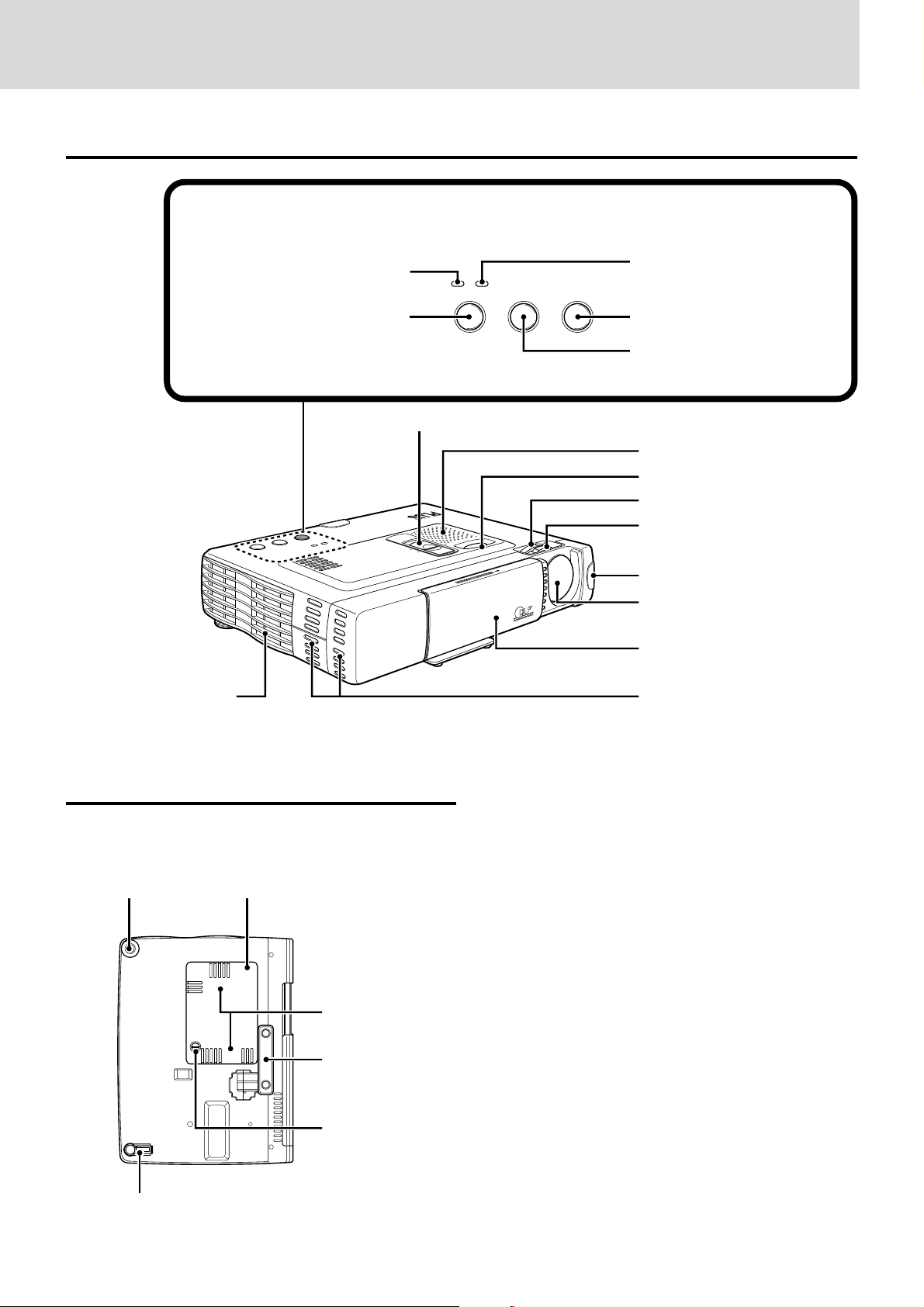
Parts and controls
For operational instructions, refer to the page indicated in brackets.
Top, front and side panel view
Control panel
Exhaust vents [3]
POWER indicator [14,16]
POWER button [14,16]
POWER
P
O
W
E
R
SOURCE
S
TA
T
U
S
AUTO
PLUS
POWER STATUS
POWER SOURCE AUTO
“COLOR” “B/W” switch*1 [19B]
B / W
COLOR
OPEN
STATUS indicator [32]
AUTO button [18]
SOURCE button [14, 16]
Speaker [10, 18]
Adjuster button [15]
Zoom ring*2 [15]
Focus ring [15]
Remote Sensor [5]
Lens [3, 9]
Sliding lens cap [3, 14]
Ventilation slots [3]
Bottom
Rear adjuster [15]
Lamp cover [33]
Ventilation slots [3]
Front adjuster [15]
Lamp cover screw [33]
*1Applicable models: U3-1100WZ, U3-1100W, U3-810WZ,
and U3-810W
2
U3-1100WZ and U3-810WZ
*
Adjustment foot [15]
E – 6
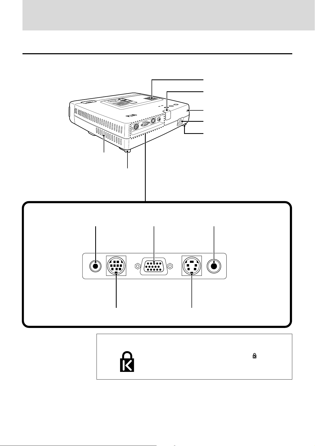
Rear and side panel view
Ventilation slots [3]
Terminal Panel
COLOR
B / W
R
E
W
O
P
TO
U
A
S
U
E
AT
C
R
ST
OU
S
ER
W
O
P
Built-in security slot [see below]
Remote sensor [5]
EO
ID
V
O
E
VID
S
bCr
B / YC
RG
USE
O
M
IO
UD
A
AC IN terminal [14]
Rear adjuster [15]
Ventilation slots [3]
Adjustment foot [15]
AUDIO jack [10, 11, 12] VIDEO jack [10]
RGB/YCbCr connector [11, 12]
AUDIO MOUSE RGB
MOUSE connector [17]
Built-in Security Slot
/
YCbCr
E – 7
VIDEOS-VIDEO
S-VIDEO jack [10]
This security slot supports the MicroSaver® Security
System. MicroSaver® is a registered trademark of
Kensington Microware Inc. The logo is trademarked and owned by Kensington Microware Inc.
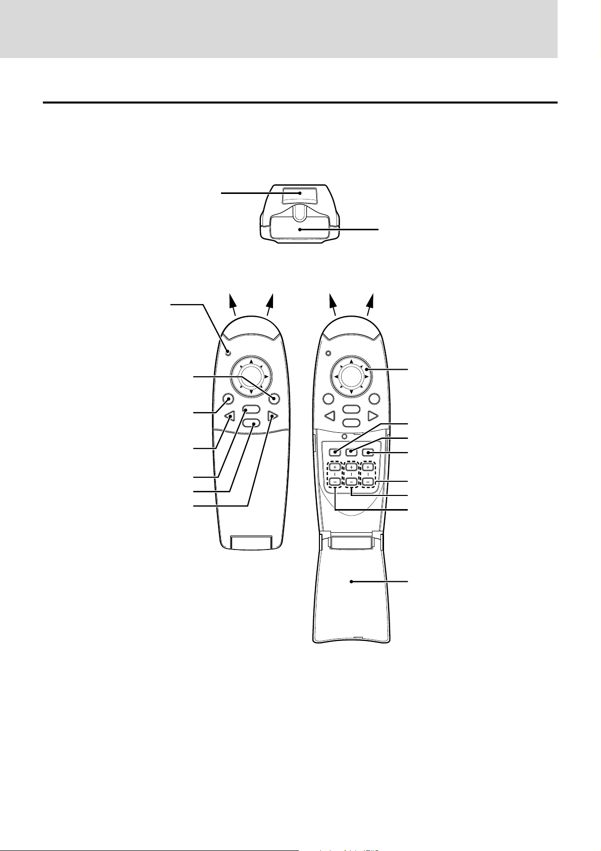
Parts and controls (continued)
Wireless Remote Control
ENTER button [17, 25]
LED
The red LED lights during
infrared sending.
Infrared transmitter [5]
POWER button [14, 16]
MOUSE button [17]
VIDEO button [16]
MENU button [20]
CANCEL button [17, 22]
RGB button [16]
MOUSE POWER
MENU
VIDEO
CANCEL
RGB
PLUS
MOUSE POWER
MENU
VIDEO
AUTO FREEZE MUTE
ZOOM VOLUMEKEYSTONE
CANCEL
RGB
Cursor key [17, 19A, 22]
AUTO button [18]
FREEZE button [18]
MUTE button [18]
VOLUME +/– button [18]
KEYSTONE +/– button [18]
ZOOM +/– button [19A]
FLIP COVER [18, 20]
Note
The remote controller supplied with this unit is a Class 1 LED
product.
E – 8
Installation
The distance from the unit lens to the screen determines to the size of the projected image, therefore, you need to consider the place where you set
up the unit and screen before making connections. You also need to consider the screen size and height of the unit and screen as other important factors.
Tip
A non-glossy wall may be used as a substitute for a screen.
WARNING
• Carrying the unit
Always carry the unit in the carrying case. Ensure that the power cable and any other cables connecting to video sources are disconnected
before moving the unit. When moving the unit or when it is not in use, cover the lens with the sliding lens cap.
• Only use the unit on a solid flat level surface. If the unit falls to the ground, you may be injured and the unit may severely be damaged.
• Do not use the unit where temperatures vary greatly. The unit must be used at temperatures between 5°C (41°F) and 35°C (95°F).
• Do not expose the unit to moisture, dust, or smoke. This will harm the screen image.
•
Ensure that you have adequate ventilation around the unit to allow heat dissipation. Do not cover the vents on the bottom or the side of the unit.
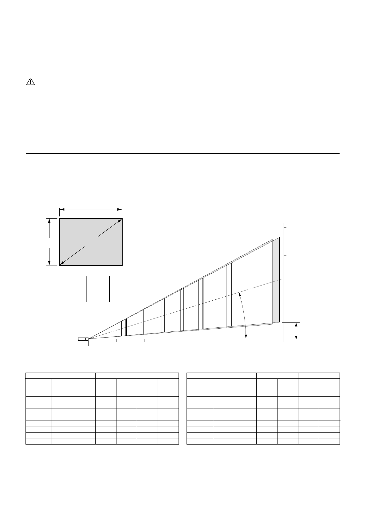
Installation Guidelines (normal installation)
This section explains how to determine the screen size you use. Use the following table and charts as a guide.
Optimum focal point from the lens surface is as follows:
3.9 feet - 22.3 feet / 1.2 m - 6.8 m (U3-810W, U3-810SF) 3.9 feet - 21.6 feet / 1.2 m - 6.6 m (U3-1100W, U3-1100SF)
3.9 feet - 32.2 feet / 1.2 m - 9.8 m (U3-810WZ) 3.9 feet - 30.8 feet / 1.2 m - 9.4 m (U3-1100WZ)
Distance and image size for U3-1100W, U3-1100SF, U3-810W and U3-810SF
Screen width
[Screen height]
4m (13.1 feet)
200"
Screen height
Screen size (diagonal)
150"
3m (9.8 feet)
[Screen size]
U3-810U3-1100
100"
80"
60"
U3-810 : 35"
U3-1100 : 36"
Lens surface
40"
1m
(3.3feet)2m(6.6 feet)3m(9.8 feet)4m(13.1 feet)5m(16.4 feet)6m(19.7 feet)7m(23.0 feet)
[Projection distance]
Screen
size (inch)
35”
36”
40”
60”
80”
100”
120”
150”
200”
Screen dimensions
width x height (cm)
71.1
X
73.2
81.3
121.9
162.6
203.2
243.8
304.8
406.4
53.3
X
54.9
X
61.0
X
91.4
X
121.9
X
152.4
X
182.9
X
228.6
X
304.8
Notes
• The range of error is +/- 5% because the distances are calculated values.
•Move the unit to the position where the projected image is horizontally centered to the screen.
• Do not use the unit where temperatures vary greatly. The unit must be used at temperatures between 5˚C (41˚F) and 35˚C (95˚F).
•To raise the projection position, place the unit on the stable table.
• If strong light falls on the remote sensor, the remote control may not function. Do not place the unit in direct lightning.
•For best results, do not expose the screen to direct sunlight or strong light.
U3-810W, U3-810SF U3-1100W, U3-1100SF
1.2
1.3
2.0
2.6
3.3
4.0
5.0
6.6
-
Height H
(cm)
-
9.8
10.4
15.7
20.9
26.1
31.3
39.2
52.2
Projection
distance (m)
1.2
1.2
1.4
2.1
2.7
3.4
4.1
5.1
6.8
Height H
(cm)
10.5
10.8
12.0
18.0
24.0
30.0
36.0
44.9
59.9
Projection
distance (m)
120"
Screen
size (inch)
35”
36”
40”
60”
80”
100”
120”
150”
200”
17.2˚
Distance from center of lens to lower edge of screen
Screen dimensions
width x height (inch)
28.0
X
X
X
X
X
X
X
X
X
21.0
21.6
24.0
36.0
48.0
60.0
72.0
90.0
120.0
28.8
32.0
48.0
64.0
80.0
96.0
120.0
160.0
2m (6.6 feet)
1m (3.3feet)
H
U3-810W, U3-810SF U3-1100W, U3-1100SF
Projection
distance (feet)
3.9
3.9
4.6
6.9
8.9
11.2
13.5
16.7
22.3
Height H
(inch)
4.1
4.3
4.7
7.1
9.4
11.8
14.2
17.7
23.6
distance (feet)
Center of lens
3.9
4.3
6.6
8.5
Height H
(inch)
-
3.9
4.1
6.2
8.2
10.3
12.3
15.4
20.6
Projection
10.8
13.1
16.4
21.6
-
E – 9A
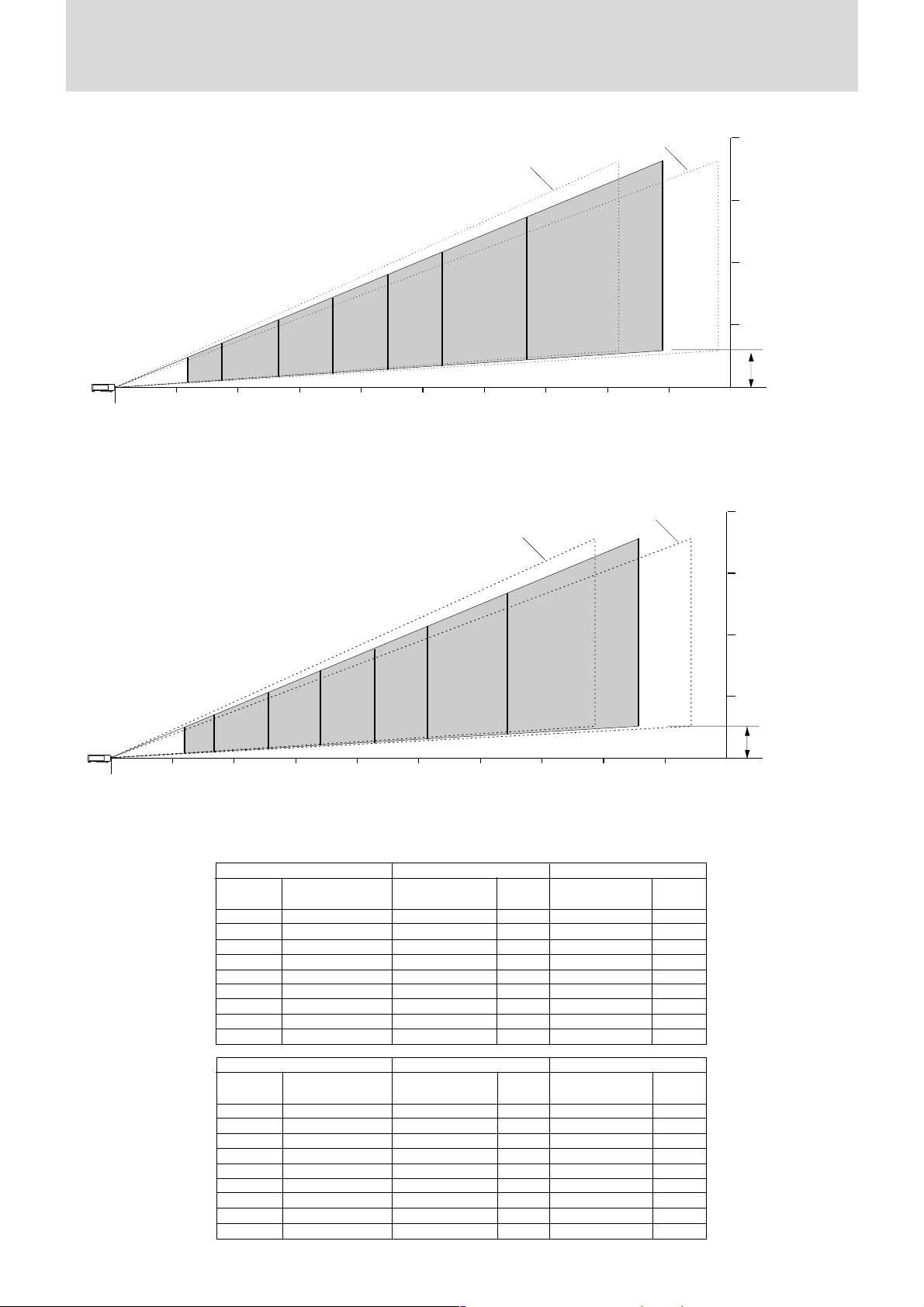
Distance and image size for U3- 810WZ and U3- 1100WZ
The drawings show the image sizes and distances for tele and wide.
Wide (max)
Tele (max)
200"
[Screen height]
4m (13.1 feet)
Lens surface
[Screen size]
120"
100"
80"
60"
40"
25"
1m
(3.3feet)2m(6.6 feet)3m(9.8 feet)4m(13.1 feet)5m(16.4 feet)6m(19.7 feet)7m(23.0 feet)8m(26.2 feet)9m(29.5 feet)
150"
[Projection distance]
Projection distance and screen height for U3-810WZ
Tele (max)
200"
26"
40"
60"
[Screen size]
100"
80"
Wide (max)
150"
120"
3m (9.8 feet)
2m (6.6 feet)
1m (3.3feet)
H
Center of lens
Distance from center of
lens to lower edge of
screen
[Screen height]
4m (13.1 feet)
3m (9.8 feet)
2m (6.6 feet)
1m (3.3feet)
Lens surface
1m
(3.3feet)2m(6.6 feet)3m(9.8 feet)4m(13.1 feet)5m(16.4 feet)6m(19.7 feet)7m(23.0 feet)8m(26.2 feet)9m(29.5 feet)
[Projection distance]
Projection distance and screen height for U3-1100WZ
U3-810WZ U3-1100WZ
Projection distance (m)
Wide - Tele
Height H
1.20
1.22
1.6 - 1.9
2.4 - 2.9
3.2 - 3.9
4.1 - 4.9
4.9 - 5.9
6.1 - 7.4
8.2 - 9.8
Projection distance (m)
(cm)
7.6
7.6
12.0
18.0
23.9
29.9
35.9
44.9
59.9
U3-810WZ U3-1100WZ
Projection distance (feet)
Wide - Tele
3.9
4.0
5.2 - 6.2
7.9 - 9.5
10.5 - 12.8
13.5 - 16.1
16.1 - 19.4
20.0 - 24.3
26.9 - 32.2
Projection distance (feet)
Height H
(inch)
3.0
3.0
4.7
7.1
9.4
11.8
14.1
17.7
23.6
Wide - Tele
–
1.2
1.5 - 1.9
2.3 - 2.8
3.1 - 3.7
3.9 - 4.7
4.7 - 5.6
5.9 - 7.1
7.9 - 9.4
Wide - Tele
–
3.9
4.9 - 6.2
7.5 - 9.2
10.2 - 12.1
12.8 - 15.4
15.4 - 18.4
19.4 - 23.3
25.9 - 30.8
Height H
(cm)
–
6.8
10.4
15.5
20.7
25.9
31.1
38.9
51.8
Height H
(inch)
–
2.7
4.1
6.1
8.1
10.2
12.2
15.3
20.4
Screen
size (inch)
25”
26”
40”
60”
80”
100”
120”
150”
200”
Screen
size (inch)
25”
26”
40”
60”
80”
100”
120”
150”
200”
Screen dimensions
width x height (cm)
50.8
52.8
81.3
121.9
162.6
203.2
243.8
304.8
406.4
Screen dimensions
width x height (inch)
20.0
20.8
32.0
48.0
64.0
80.0
96.0
120.0
160.0
38.1
X
39.6
X
61.0
X
91.4
X
121.9
X
152.4
X
182.9
X
228.6
X
304.8
X
15.0
X
15.6
X
24.0
X
36.0
X
48.0
X
60.0
X
72.0
X
90.0
X
120.0
X
H
Center of lens
Distance from center of
lens to lower edge of
screen
E – 9B
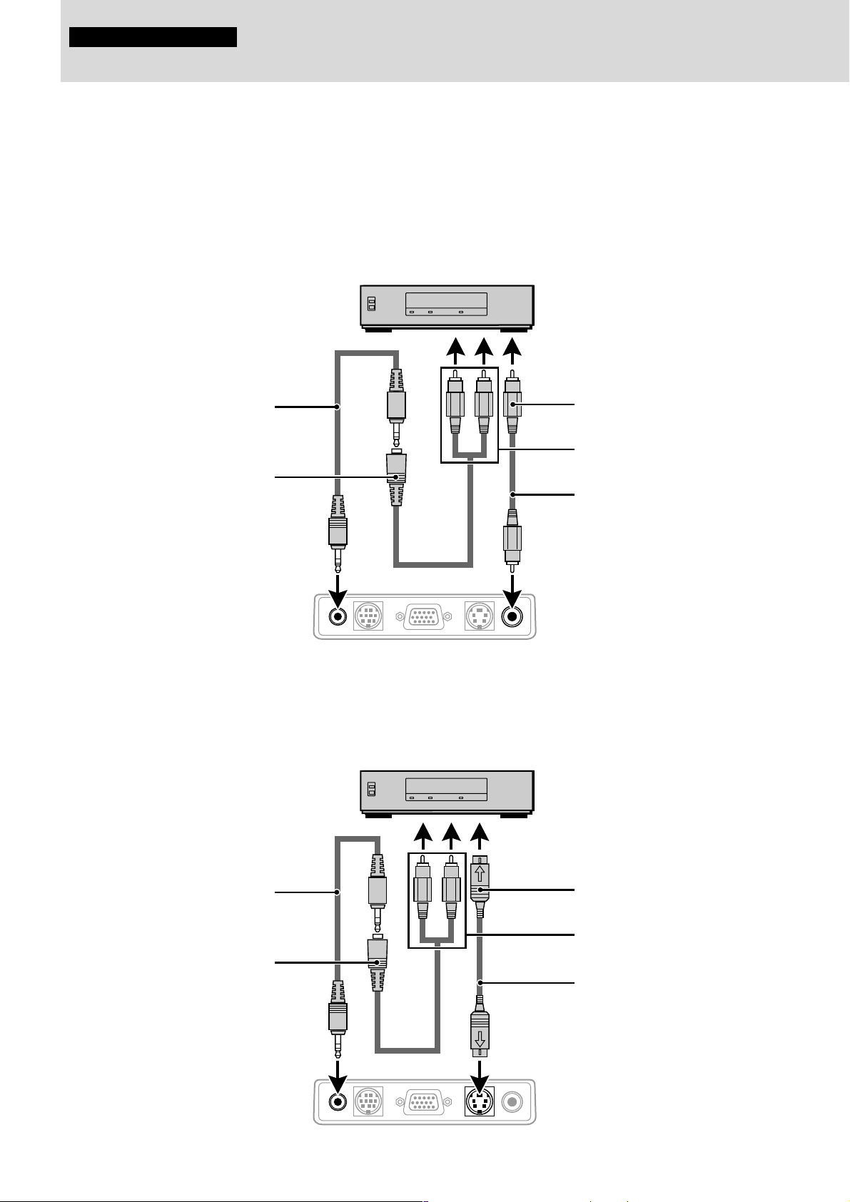
Connections
Connecting video equipment
You can connect up to two pieces of video equipment to the unit following the illustrations below.
•You can switch the input source (picture) to VIDEO or S-VIDEO when you connect two pieces of equipment.
(The S-VIDEO connection provides more vivid color and higher resolution compared to the VIDEO connection.)
•You can output the sound of only one component through the unit speaker even when two components are connected.
When connecting two external units, the audio from either one of these units can be output from the speaker of this device. Audio can be
turned on and off for video related input (video, S-video) from the menu or RGB (or YCbCr) input. (see page 28)
Connection to the VIDEO jack of the unit
VCR/DVD player/laser disc player, etc.
(L) (R)
White Red Yellow
Audio cable (accessory)
Audio adaptor (accessory)
Rear panel jacks of this device
AUDIO MOUSE RGB
Connection to the S-VIDEO jack of the unit
VCR/DVD player/laser disc player, etc.
/
YCbCr
To video out jack
To audio out jack
Video cable (accessory)
VIDEOS-VIDEO
Audio cable (accessory)
Audio adaptor (accessory)
Rear panel jacks of this device
(L)
White
AUDIO MOUSE RGB
E – 10
(R)
Red Yellow
/
YCbCr
To S-video out jack
To audio out jack
S-video cable (accessory)
VIDEOS-VIDEO
 Loading...