

Page 1
USER’S MANUAL
U3-1080/U3-880
DATA PROJECTOR
English
C
E
A
U
T
OS
Français
Deutsch
P
O
P
W
O
W
E
E
R
R
O
U
R
S
T
A
T
U
S
O
P
EN
Italiano
Español
PLUS
Page 2

Note:
This equipment has been tested and found to
comply with the limits for a Class A digital device,
pursuant to Part 15 of the FCC Rules. These limits
are designed to provide reasonable protection
against harmful interference when the equipment
is operated in a commercial environment. This
equipment generates, uses, and can radiate radio
frequency energy and, if not installed and used in
accordance with the instruction manual, may
cause harmful interference to radio
communications. Operation of this equipment in
a residential area is likely to cause harmful
interference in which case the user will be required
to correct the interference at his own expense.
PLUS CORPORATION
IMPORTANT
Digital Light Processing, DLP, Digital Micromirror Device and DMD are all
trademarks of Texas Instruments.
Windows 98, Windows 95, and Windows 3.1 are registered trademarks in the
United States and other countries of Microsoft Corporation.
IBM is a registered trademark of International Business Machines Corporation.
Macintosh and MAC are trademarks of Apple Computer Inc.
Other names of companies and products mentioned are trademarks and registered
trademarks of the respective companies.
TM
, ® and © marks are not used in this document.
Page 3
USER’S MANUAL
U3-1080/U3-880
English
Page 4
IMPORTANT SAFETY INFORMATION
Precautions
Please read this manual carefully before using your PLUS U3-1080/U3-880 Data Projector and keep the manual handy for future
reference.
Your serial number is located next to the main power switch on the back of the unit. Record it here:
CAUTION
TO PREVENT SHOCK, DO NOT OPEN THE CABINET. NO USER-SERVICEABLE PARTS INSIDE.
REFER SERVICING TO QUALIFIED PLUS SERV I CE P E R S O N N E L .
WARNING
TO PREVENT FIRE OR SHOCK, DO NOT EXPOSE THIS UNIT TO RAIN OR MOISTURE. DO
NOT USE THIS UNIT’S GROUNDED PLUG
WITH AN EXTENSION CORD OR IN AN OUTLET UNLESS ALL THREE PRONGS CAN BE
FULLY INSERTED. DO NOT OPEN THE CABINET. THERE ARE HIGH-VOLTAGE COMPONENTS INSIDE. ALL SERVICING MUST BE
DONE BY QUALIFIED PLUS SERVICE PERSONNEL.
WARNING
This is a class A product. In a domestic environment this
product may cause radio interference in which case the user
may be required to take adequate measures.
Important Safeguards
RF Interference
WARNING
The Federal Communications Commission does not allow
any modifications or changes to the unit EXCEPT those
specified by PLUS Technologies in this manual. Failure to
comply with this government regulation could void your
right to operate this equipment.
This equipment has been tested and found to comply with
the limits for a Class A digital de vice, pursuant to Part 15 of
the FCC Rules. These limits are designed to provide
reasonable protection against harmful interference when
the equipment is operated in a commercial environment.
This equipment generates, uses, and can radiate radio
frequency energy and, if not installed and used in
accordance with the instruction manual, may cause
harmful interference to radio communications. Operation
of this equipment in a residential area is likely to cause
harmful interference in which case the user will be required
to correct the interference at his own expense.
These safety instructions are to ensure the long life of the unit and to prevent fire and shock. Please read them carefully and heed all w arnings.
Installation
• For best results, use the unit in a darkened room.
• Place the unit on a flat, level surface in a dry area away from dust
and moisture.
• Do not place the unit in direct sunlight, near heaters or heat
radiating appliances.
• Exposure to direct sunlight, smoke or steam can harm internal
components.
• Handle the unit carefully. Dropping or jarring can damage inter nal components.
• Do not place heavy objects on top of the unit.
Power Supply
• The unit is designed to operate on a power supply of 100 to 120
and 220 to 240 V 50/60 Hz AC. Ensure that your power supply
fits these requirements before attempting to use the unit.
• For PLUGGABLE EQUIPMENT, the socket-outlet shall be
installed near the equipment and shall be accessible.
• Handle the power cable carefully and avoid e xcessive bending. A
damaged cord can cause electric shock or fire.
• Disconnect the power cable (mains lead) from the power outlet
after using the unit.
Before disconnecting the power cable, make sure that the
POWER indicator lights in amber (not blinking or in green).
E – 2
Page 5
Table of contents
Cleaning
• Disconnect the power cable (mains lead) from the unit.
• Clean the cabinet of the unit periodically with a damp cloth. If
heavily soiled, use a mild detergent. Nev er use strong detergents
or solvents such as alcohol or thinner.
• Use a blower or lens paper to clean the lens, and be careful not to
scratch or mar the lens.
• Clean the ventilation slots and speaker grills on the unit
periodically using a vacuum cleaner . If accumula ted dust blocks
the ventilation slots, the unit will overheat, which may cause the
unit to malfunction.
Use a soft brush attachment when using the vacuum cleaner. Do
not use a hard attachment, such as a crevice tool, to prevent the
damage to the unit.
Lamp Replacement
• Be sure to replace the lamp when the Status indicator comes on.
If you continue to use the lamp after 1000 hours of usage, the
lamp will turn off.
Fire and Shock Precautions
• Ensure that there is sufficient ventilation and that vents are
unobstructed to prevent the buildup of heat inside the unit. Allow
at least 10 cm (3 inches) of space between the unit and walls.
• Prevent foreign objects such as paper clips and bits of paper from
falling into the unit. Do not attempt to retrieve any objects that
fell into the unit. Do not insert any metal objects such as a wire or
screwdriver into the unit. If something should fall into the unit,
immediately disconnect the power cable from the unit and have
the object removed by a qualified PLUS service person.
• Do not place any liquids on top of the unit.
• Do not look into the lens while the unit is on. Serious damage
to your eyes could result.
Carrying around
When carrying the unit around, please use the carrying case that
comes with it and, to protect the lens from scratches, always shut
the sliding lens cap. Also, do not subject the unit to strong
mechanical shock.
IMPORTANT SAFETY INFORMATION................................... 2
Table of contents ........................................................................... 3
Basic information and preparations ........ 4
Features ......................................................................................... 4
Checking the supplied accessories ............................................... 4
Preparing the remote control ........................................................ 5
Parts and controls .......................................................................... 6
Installation..................................................................................... 9
Connections ............................................ 10
Connecting video equipment ...................................................... 10
Connecting Video Equipment With Component Video Signal
(YCbCr) Output .......................................................................... 11
Connecting a PC or Macintosh ................................................... 12
Operation ................................................. 14
Using the unit .............................................................................. 14
Using the Remote Control (Input Selection).............................. 16
Using the Remote Control as the PC Mouse.............................. 17
Various functions while using the unit ....................................... 18
Menu operation....................................... 20
Menu Structure............................................................................ 20
Adjusting the picture elements ................................................... 22
Adjusting the projected image from the computer .................... 23
Manual Adjustment of Personal Computer Images ................... 24
Resetting...................................................................................... 25
Resetting the Lamp Hours of Usage........................................... 25
Setting Narrow Images (Advanced Menu)................................. 26
Setting in Accordance With Image Contents.............................. 27
Initial Settings ............................................................................. 28
Setting the Menu ......................................................................... 30
CAUTION
Danger of explosion if battery is incorrectly replaced. Replace only with the same or equiv alent
type recommended by the manufacturer. Dispose of used batteries according to the
manufacturer’s instructions.
Others ....................................................... 31
Troubleshooting .......................................................................... 31
When the STATUS indicator lights or flashes ........................... 32
Replacing the lamp cartridge ...................................................... 33
Specifications .............................................................................. 34
E – 3
Page 6
Basic information and preparations
Checking the
Features
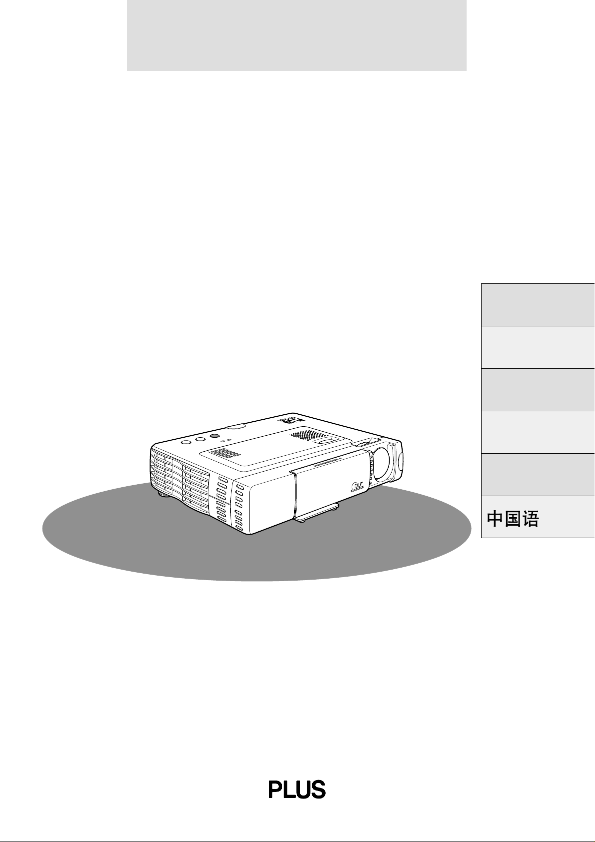
Congratulations On Your Purchase Of The U31080/U3-880 Data Projector
The U3-1080/U3-880 is one of the most spectacular data projectors
available today. The unit enables you to project precise images up
to 200 inches across (measured diagonally) from your PC or
Macintosh computer (desktop or notebook), VCR, document camera, laser disc player, DVD player, etc.
The unit can be placed on a tabletop or cart. The unit can also be
used to project images from behind the screen.*
* Consult your dealer for more information.
The other main features you’ll enjoy
• Compatible with following various color systems:
– NTSC (U.S. and Canada standard)
– PAL (Western Europe standard)
– SECAM (France and Eastern Europe standard)
– NTSC4.43 (Middle East standard)
• (U3-1080)
Superior brightness of 800 ANSI lumens, small size, and
weighing only about 1.3 kilograms/2.9 lbs.
(U3-880)
Superior brightness of 800 ANSI lumens, small size, and
weighing only about 1.3 kilograms/2.9 lbs.
Using TI’s Digital Mirror Device (DMD) and our own optical
design we have developed a geometric effect that increases the
light usage efficiency. By increasing the light usage efficiency we
can better reproduce the three basic colors (RGB) required for
color reproduction on a single DMD. This means superior brightness, smaller size, and lighter weight.
• Sharp, clear images
There is no RGB color separation, and the spaces between the
individual pixels are not noticeable. That means sharp and clear
reproduction of small characters and figures. Take a closer look
and notice the difference in quality!
• Outstanding sharp, clear, 3D like images with vivid colors
when reproducing D VD video and other high picture-quality
data/video sources
Accurate gray scale reproduction makes for more natural image
displays. DVD and other high quality image sources bring out the
true image display quality of the unit.
• Screen not distorted to a trapezoid (keystoning) when projecting to the height of the line of vision
Because the projection position is already set to the height of the
line of vision, there is no keystoning effect.
Even when projecting above or under the height of the line of
vision, image distortion (if any) can be adjusted using the keystone correction function.
• (U3-1080)
Fully compatible with true XGA; support for SXGA using
advanced intelligent compression technology
The advanced intelligent compression technology enables these
projectors to present clear compression SXGA images without any
line omission.
(U3-880)
Fully compatible with true S-VGA; support for XGA using
advanced intelligent compression technology
The advanced intelligent compression technology enables it to
present clear compression XGA images without any line omission.
• A remote control that can operate the PC or Macintosh
The supplied remote control both operates the unit and acts as a
wireless mouse control to operate the PC or Macintosh connected to the unit.
• The compact and easy to carry cabinet with its contemporary
design complements any office, board room, or auditorium.
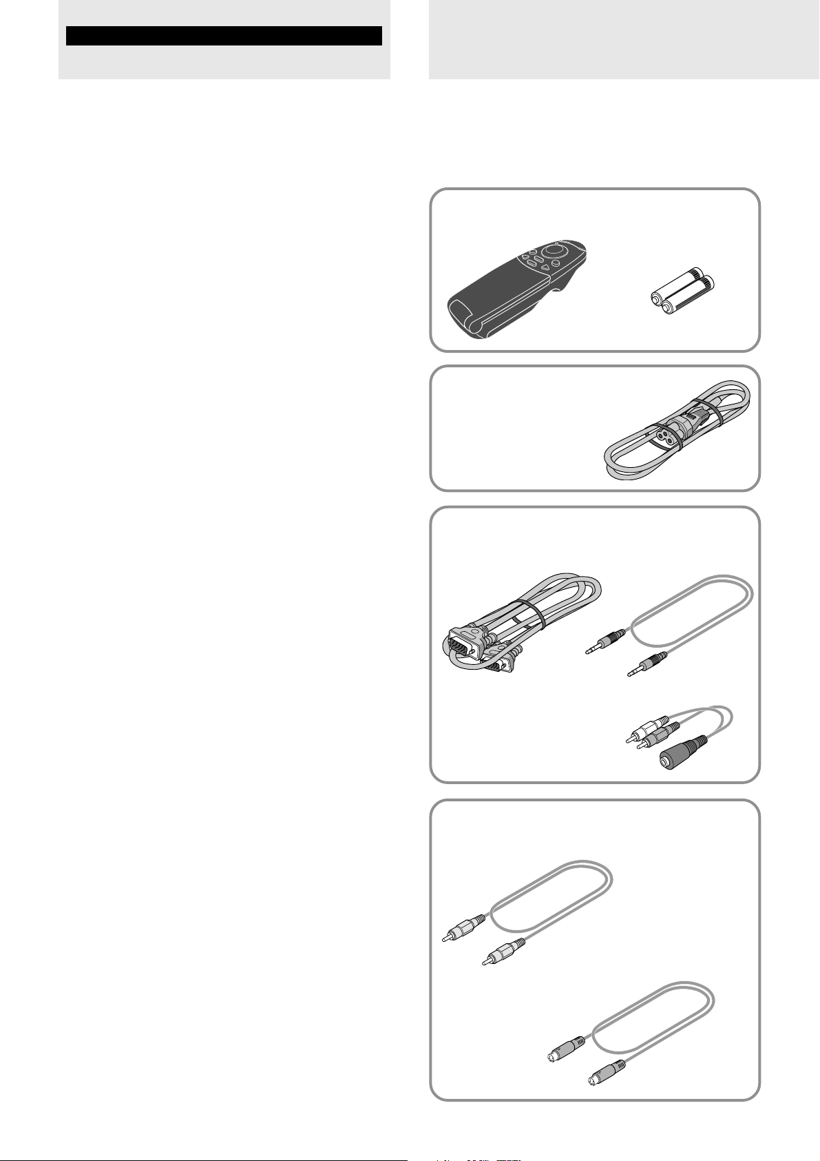
supplied accessories
Make sure your box contains everything listed below. If any
pieces are missing, contact your dealer.
Please save the original box and packing materials in case
you ever need to ship the unit.
The number of accessories is indicated in brackets.
For remote control
Remote control [1] Batteries (size AAA/R03) [2]
Power cable (mains lead)
(1.8 m/5.9 ft.) [1]
The shape of the plug varies
depending on the region where
the unit is purchased.
For computer connection
RGB cable
(1 m/3.3 ft.) [1]
No. 770708000
Audio adaptor
(mini-jack pin conversion,
0.15 m/0.5 ft) [1]
No. 770704000
For video equipment connection
Video cable
(1 m/3.3 ft.) [1]
No. 770703000
S-video cable
(1 m/3.3 ft.) [1]
No. 770709000
Audio cable
(1 m/3.3 ft.) [1]
No. 770710000
E – 4
Page 7
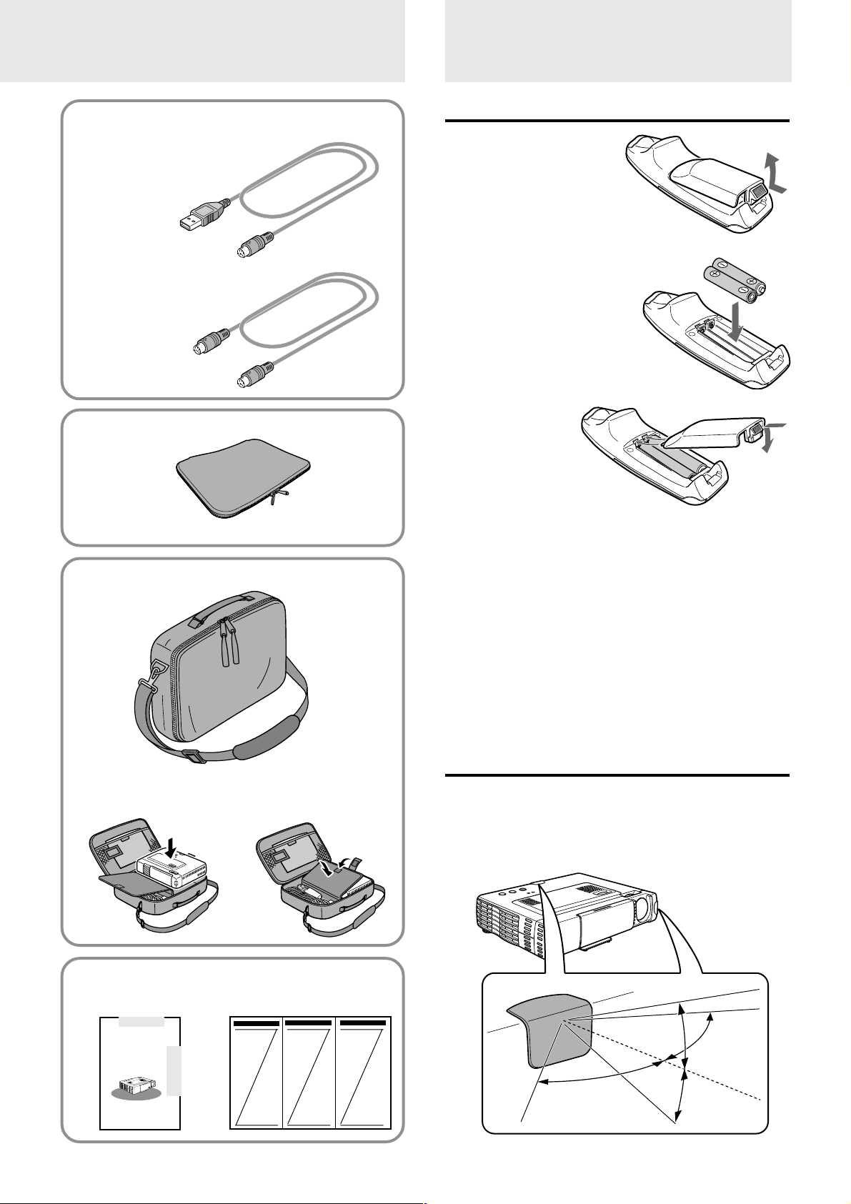
When using the remote control as computer
mouse
USB mouse cable (1 m/3.3 ft.) [1]
[for IBM / Macintosh]
No. 770707000
PS/2 mouse cable (1 m/3.3 ft.) [1]
[for IBM PS/2]
No. 770706000
Soft pouch [1]
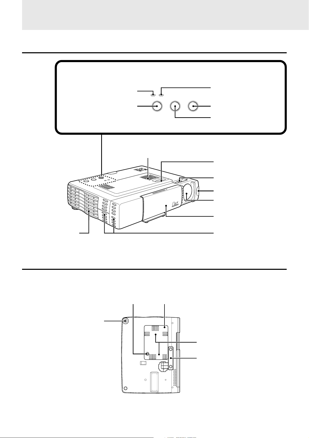
Preparing the
remote control
Inserting the batteries
1 Press firmly and slide
the battery cover off.
2 Insert the two supplied
batteries (size AAA/
R03). Ensure that the
polarities (+ and –) of
the batteries are aligned
correctly.
3 Slide the cover
back until it
snaps into
place.
Carrying case [1]
How to use the carrying case
Packing the unit
Packing the accessories
CAUTION
Danger of explosion if battery is incorrectly replaced. Replace only
with the same or equivalent type recommended by the manufacturer.
Dispose of used batteries according to the manufacturer’s instructions.
Notes
• If the remote control gets wet, wipe it dry immediately.
• Avoid excessive heat and humidity.
• If you will not be using the remote control for a long time, remove the
batteries.
• Do not mix new and old or different types of batteries.
• There are operations that can only be carried out by remote control.
Handle the remote control carefully.
Remote control effective range
The remote sensors are located on the front and back of the unit.
The controllable range is 50 degrees horizontally and 30 degrees
vertically relative to a line that is at a right angle to the remote
sensor. And the distance between the point of the remote control
and remote sensor must be shorter than four meters (13 feet).
USER’S MANUAL
(this manual) [1]
P
O
P
W
O
W
E
E
R
R
S
O
U
R
C
S
E
T
A
T
U
S
A
U
T
O
O
P
E
N
S
U
L
P
Quick Start Guide [1]
E – 5
50˚
30˚
30˚
50˚
Page 8
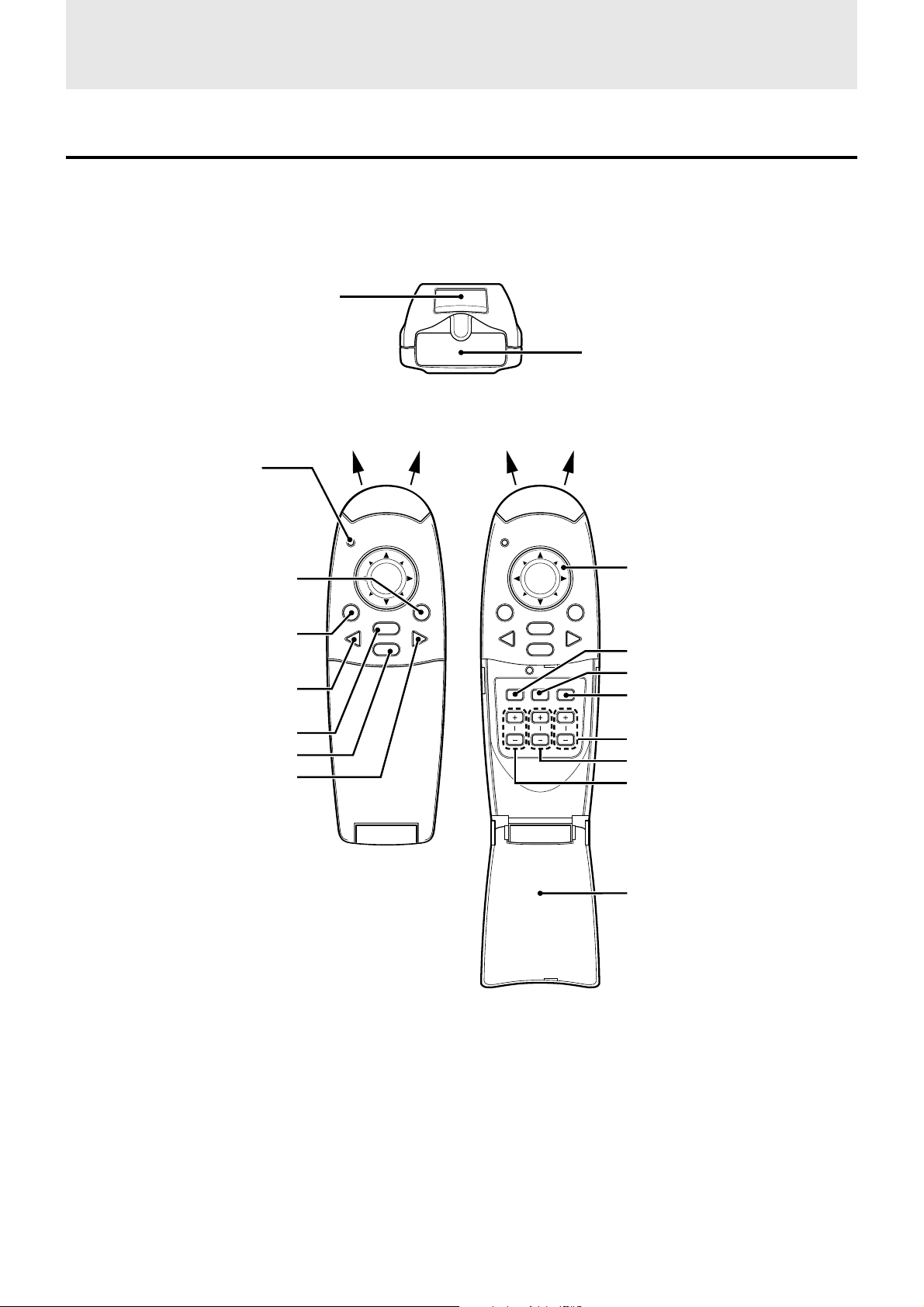
Parts and controls
For operational instructions, refer to the page indicated in brackets.
Top, front and side panel view
Control panel
Exhaust vents [3]
POWER indicator [14,16]
POWER button [14,16]
P
O
P
W
O
W
E
E
R
R
O
U
R
C
S
E
T
A
T
U
S
A
U
T
OS
PLUS
STATUS indicator [32]
POWER STATUS
POWER SOURCE AUTO
AUTO button [18]
SOURCE button [14, 16]
Speaker [10, 18]
Adjuster button [15]
Focus ring [15]
OPEN
Remote Sensor [5]
Lens [3, 9]
Sliding lens cap [3, 14]
Ventilation slots [3]
Bottom
Lamp cover screw [33]
Rear adjuster [15]
Lamp cover [33]
Ventilation slots [3]
Front adjuster [15]
E – 6
Page 9
Rear and side panel view
W
O
P
ER S
Ventilation slots [3]
Remote sensor [5]
O
T
U
A
US
T
E
C
TA
R
U
O
S
R
E
W
O
P
Built-in security slot [see below]
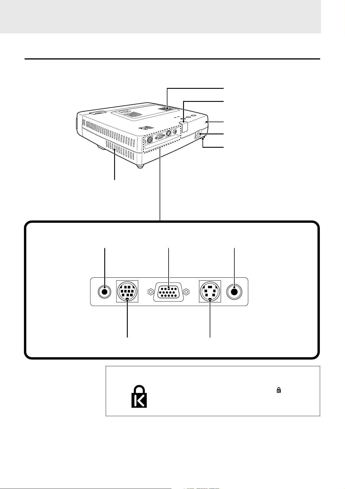
Terminal Panel
O
E
ID
V
O
E
ID
V
S
r
C
b
C
/ Y
B
G
R
E
S
U
O
M
IO
D
AU
AC IN terminal [14]
Rear adjuster [15]
Ventilation slots [3]
AUDIO jack [10, 11, 12] VIDEO jack [10]
RGB/YCbCr connector [11, 12]
AUDIO MOUSE RGB
MOUSE connector [17]
Built-in Security Slot
/
YCbCr
E – 7
VIDEOS-VIDEO
S-VIDEO jack [10]
This security slot supports the MicroSaver® Security
System. MicroSaver® is a registered trademark of
Kensington Microware Inc. The logo is trademarked and owned by Kensington Microware Inc.
Page 10
Parts and controls (continued)
Wireless Remote Control
ENTER button [17, 25]
LED
The red LED lights during
infrared sending.
Infrared transmitter [5]
POWER button [14, 16]
MOUSE button [17]
VIDEO button [16]
MENU button [20]
CANCEL button [17, 22]
RGB button [16]
MOUSE POWER
MENU
VIDEO
CANCEL
RGB
PLUS
MOUSE POWER
MENU
VIDEO
AUTO FREEZE MUTE
ZOOM VOLUMEKEYSTONE
CANCEL
RGB
Cursor key [17, 19, 22]
AUTO button [18]
FREEZE button [18]
MUTE button [18]
VOLUME +/– button [18]
KEYSTONE +/– button [18]
ZOOM +/– button [19]
FLIP COVER [18, 20]
E – 8
Page 11
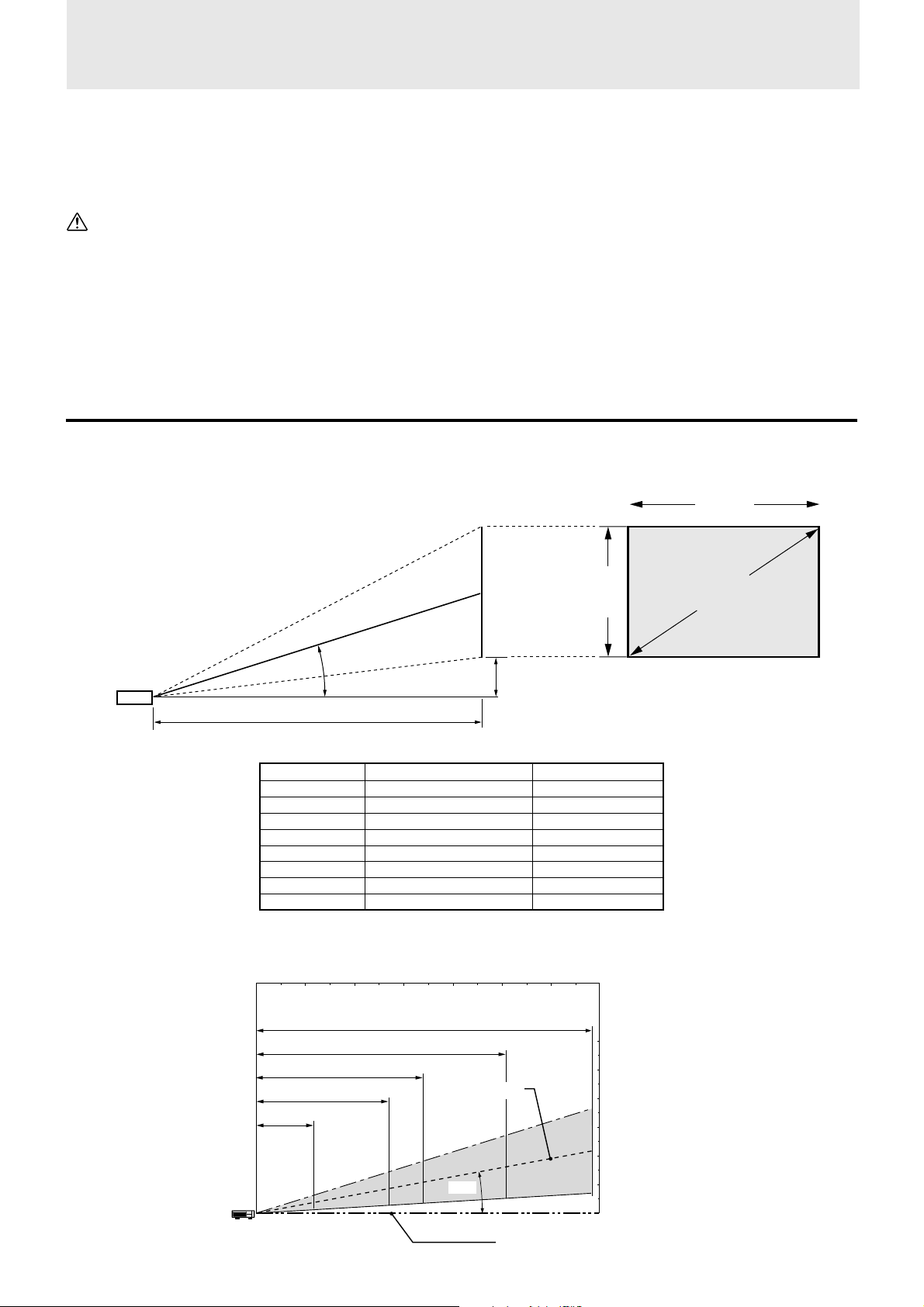
Installation
The distance from the unit lens to the screen determines to the size of the projected image, therefore, you need to consider the place where you
set up the unit and screen before making connections. You also need to consider the screen size and height of the unit and screen as other
important factors.
Tip
A non-glossy wall may be used as a substitute for a screen.
WARNING
• Carrying the unit
Always carry the unit in the carrying case. Ensure that the power cable and any other cables connecting to video sources are disconnected
before moving the unit. When moving the unit or when it is not in use, cover the lens with the sliding lens cap.
• Only use the unit on a solid flat level surface. If the unit falls to the ground, you may be injured and the unit may severely be damaged.
• Do not use the unit where temperatures vary greatly. The unit must be used at temperatures between 5°C (41°F) and 35°C (95°F).
• Do not expose the unit to moisture, dust, or smoke. This will harm the screen image.
• Ensure that you have adequate ventilation around the unit to allow heat dissipation. Do not co ver the vents on the bottom or the side of the
unit.
Positioning the unit
The projected image becomes larger as the distance between the unit and screen increases. The minimum image size is about 36 inches
diagonally at a distance of about 1.2 m (approx. 3.9 feet) and the maximum size is approx. 200 inches at a distance of 6.8 m (approx. 22.3 feet)
from the screen. Use the following information when you fix the position of the unit.
Projecting distance and image size
Projection distance
Screen size Projection distance Dimension (H)
inches m / feet cm / inch
36 1.2 /3.93 9.9 / 3.90
60 2.0 /6.56 16.9 /6.65
80 2.7 /8.85 22.5 /8.86
100 3.4 /11.15 28.1 /11.06
120 4.1 /13.45 33.7 /13.27
150 5.1 /16.73 42.2 /16.61
200 6.8 /22.30 56.2 /22.13
0123456 (m)
0 3.3 6.6 9.8 13.1 16.4 19.7 (feet)
17.3 degrees
Projection distance
Screen
Screen
width
Screen
Height
Distance from center of lens to lower edge of screen
(represented as “H” in the table below)
Screen size
(diagonal)
200″
150″
100″
80″
36″
2.7 m / 8.85 feet
1.2 m / 3.93 feet
5.1 m / 16.73 feet
3.4 m / 11.15 feet
Diagonal image size (inch)
6.8 m / 22.30 feet
Center of image
17.3˚
E – 9
Height of the
projecting image
5 m / 16.4 feet
4 m / 13.1 feet
3 m / 9.8feet
2 m / 6.6 feet
1 m / 3.3 feet
0 m / 0 feet
Center of lens
Page 12
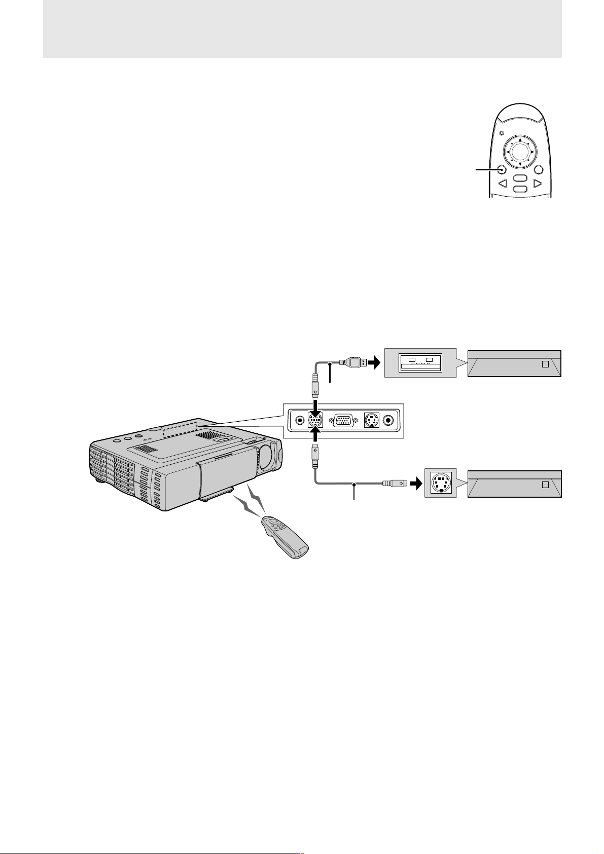
Connections
Connecting video equipment
You can connect up to two pieces of video equipment to the unit following the illustrations below.
• You can switch the input source (picture) to VIDEO or S-VIDEO when you connect two pieces of equipment.
(The S-VIDEO connection provides more vivid color and higher resolution compared to the VIDEO connection.)
• You can output the sound of only one component through the unit speaker even when two components are connected.
When connecting two external units, the audio from either one of these units can be output from the speaker of this device. Audio can be
turned on and off for video related input (video, S-video) from the menu or RGB (or YCbCr) input. (see page 28)
Connection to the VIDEO jack of the unit
VCR/DVD player/laser disc player, etc.
(L) (R)
White Red Yellow
Audio cable (accessory)
Audio adaptor (accessory)
Rear panel jacks of this device
AUDIO MOUSE RGB
Connection to the S-VIDEO jack of the unit
VCR/DVD player/laser disc player, etc.
/
YCbCr
To video out jack
To audio out jack
Video cable (accessory)
VIDEOS-VIDEO
Audio cable (accessory)
Audio adaptor (accessory)
Rear panel jacks of this device
(L)
White
AUDIO MOUSE RGB
E – 10
(R)
Red Yellow
/
YCbCr
To S-video out jack
To audio out jack
S-video cable (accessory)
VIDEOS-VIDEO
Page 13
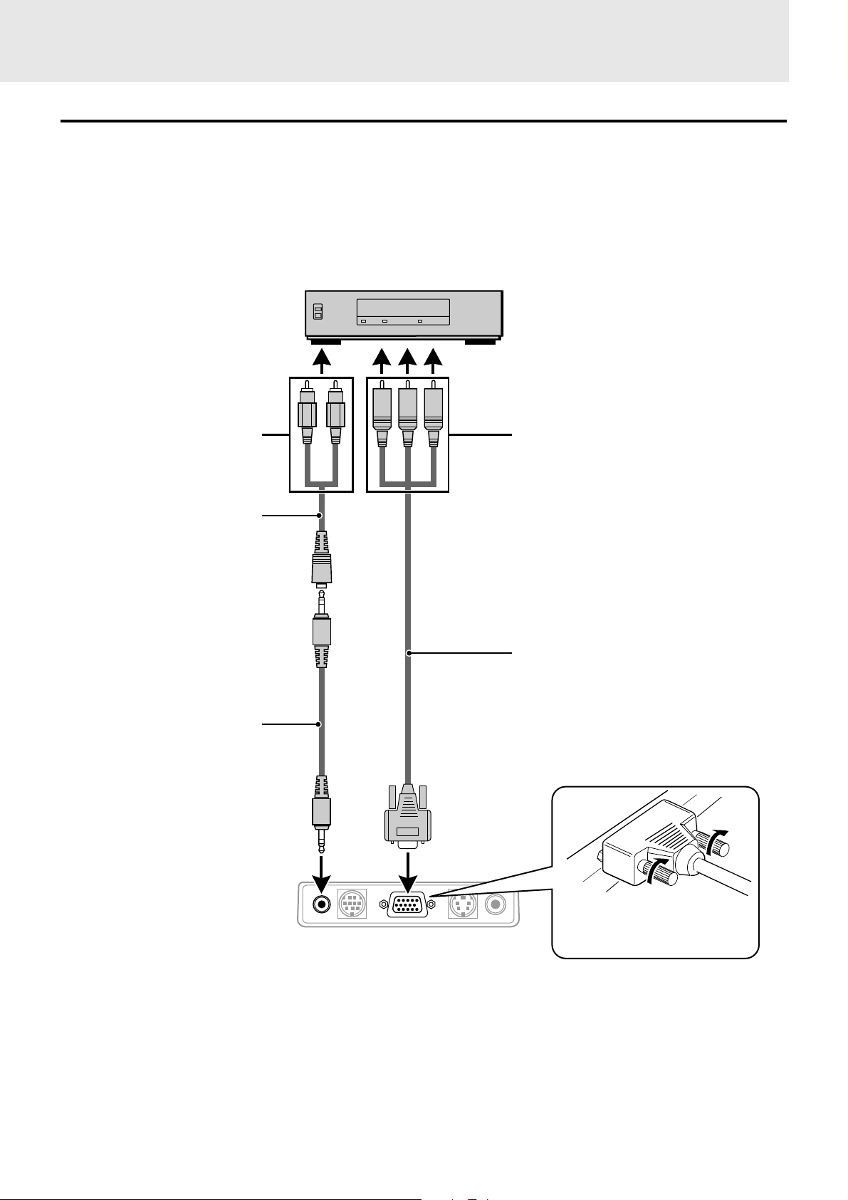
Connecting Video Equipment With Component Video Signal (YCbCr) Output
• Video equipment with component video signal (YCbCr) output can be connected to this projector by setting the RGB/YCbCr connector to
YCbCr (see page 27) from the menu.
Connection to the RGB/YCbCr connector
DVD player
(Cb)
(L)
White
(R)
(Y)
Red
Green Blue Red
(Cr)
To audio out jack
Audio adaptor (accessory)
Audio cable (accessory)
To component video (YCbCr) OUT jack
Component cable* (YCbCr cable: option)
* Model name: UP-106
Jacks: RCA × 3 mini D-Sub 15-pin
Rear panel jacks of this device
AUDIO MOUSE RGB
/
YCbCr
E – 11
VIDEOS-VIDEO
Plug in the connection cable
and tighten the screws.
Page 14
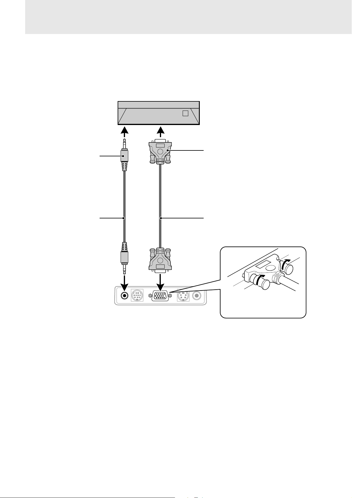
Connecting a PC or Macintosh
This projector can be used as a display for numerous applications by connecting the analog RGB output connector of a PC to the RGB/YCbCr
jack of this projector and setting the RGB/YCbCr connector to RGB (see page 27).
• Either read the instruction manual or contact the manufacturer concerning the method used to set your PC.
● IBM PC/AT compatible
● Macintosh mini D-sub 15-pin monitor output
connector.
To headphone jack
Audio cable (accessory)
Rear panel jacks of this device
AUDIO MOUSE RGB
/
YCbCr
Mini D-Sub 15-pin connector
RGB cable (accessory)
VIDEOS-VIDEO
Plug in the connection cable
and tighten the screws.
E – 12
Page 15

Changing the computer’s video
resolutions
Notebook computers and resolution
standards
Depending on your computer's graphics capability, you may be
able to select one of several resolutions. Generally a computereither a PC or Macintosh- with 1 MB VRAM will generally run:
640 × 480 at 16.7 million colors (24 bit true color)
800 × 600 at 65,000 colors.
1024 × 768 at 256 colors.
As the resolution increases, the number of colors you can run
decreases. With 2 MB VRAM a computer will generally run:
640 × 480 at 16.7 million colors (24 bit true color).
800 × 600 at 16.7 million colors (24 bit true color).
1024 × 768 at 65,000 colors.
1280 × 1024 at 256 colors.
Windows 98/Windows 95
There are two methods you can use to change your resolution.
Method 1
1 Move your cursor to the background image and R-click.
2 In the “Properties” menu, select “Settings.”
3 Change your resolution and click “OK.”
4 You may be asked to reboot for the changes to take effect,
or a message may appear saying that “Windows is about
to resize your display.” You’ll be asked if you want to
keep your settings. Select “Yes.”
Method 2
1 Click on your “My Computer” icon.
2 Open “Control Panel” and select “Display.”
3 Change your resolution and click “OK.” after the new
resolution is selected.
4 You may be asked to reboot for the changes to take effect,
or a message may appear saying that “Windows is about
to resize your display.” You’ll be asked if you want to
keep your settings. Select “Yes.”
Windows 3.1
1 Click on the “Main” icon and open “Control Panel.”
2 Select “Change System Settings” and click on “Option.”
3 Choose “Change Display Settings.”
4 Select the resolution you want.
5 Choose the current or desired drive.
6 Restart Windows for the changes to take effect.
Macintosh
1 Under the Apple menu, select “Control Panels” and open
“Monitors.”
2 Click and open “Options.”
3 Select your new resolution and click “OK.”
(U3-1080)
The unit is designed to project industry standardized video such as
VESA (Video Electronics Standards Association) or XGA
(eXtended Graphics Array). Notebook computers do not use industry standards. They use whatev er timing is necessary to match their
local LCD display. T he end result is typically not standard. By
turning off your notebook's display, the timing parameters are a bit
more like the real VESA or XGA signal.
(U3-880)
The unit is designed to project industry standardized video such as
VESA (Video Electronics Standards Association) or VGA (Video
Graphics Array). Notebook computers do not use industry standards. They use whatever timing is necessary to match their local
LCD display. The end result is typically not standard. By turning off
your notebook display, the timing parameters are a bit more like the
real VESA or VGA signal.
Outputting Notebook Type Personal
Computer External Output Signals
When a notebook type personal computer is connected for use in
projecting, a certain amount of knowledge is necessary for cable
connection, startup and the succeeding operations. Please refer to
the instruction manual of your notebook type personal computer
when performing the following operations.
1. Make sure that this device is receiving signals
from your notebook type personal computer.
The external signal may not be output even though the LCD
screen of the notebook type personal computer indicates such
output. Check by using the INFORMATION menu displayed
by this device (page 20, 21).
If 0kHz is displayed, there is no external output signal from the
personal computer.
2. If the notebook type personal computer is not
outputting the external signal, perform the following operation.
For IBM PC/AT machines, press either the [Fn] key or one of
the [F1] - [F12] keys.
Note
When displayed on the LCD screen of a notebook type personal
computer and this device at the same time, the projected video
may not be correct even the LCD screen display is normal. In
such case, turn off the notebook type personal computer display
and try using only the external output mode. (In some cases,
external output only can be set by performing step 2 above or by
closing the LCD panel.)
E – 13
Page 16
Operation
POWER STATU
POWER SO
T
Using the unit
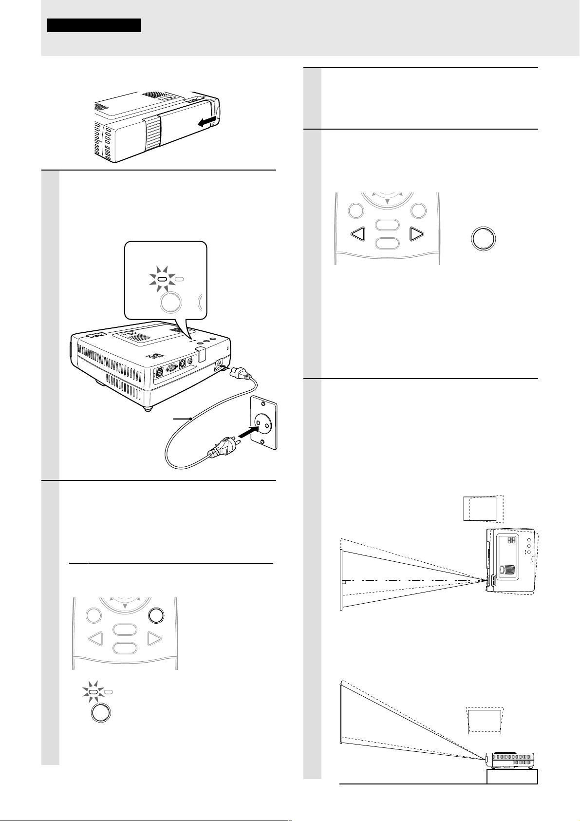
Before Using
Open the sliding lens cap.
1 Connect the power cord.
The POWER indicator will light amber, the exhaust fan will operate at slow speed and the
standby status will be activated.
Lights in amber
(Standby)
TO
AU
S
U
T
E
A
T
RC
S
U
SO
ER
W
R
O
E
P
W
O
P
O
E
ID
V
O
E
ID
V
S
r
bC
C
B / Y
G
R
E
S
U
O
M
AUDIO
1
3 Turn on the connected sour ce (computer ,
VCR, DVD player, etc.).
If you use a video component, start playback for
screen/image adjustment.
4 Select the input by pressing either the
VIDEO or RGB button of the remote control, or the SOURCE button of this device
(refer to page 16).
MOUSE POWER
VIDEO
MENU
RGB
CANCEL
Notes
• If the blue or black screen (the background type differs
depending on the “BACKGROUND” setting. See page 28.)
is projected, check the following:
– Is the source properly connected to the unit?
– Is the source component or computer turned on?
– Are the video signals coming to the unit?
• The video resolution of the connected computer can be
changed. See page 13.
SOURCE
5 Adjust the position and height of the unit.
Power cable
(supplied)
2
2 Press POWER on the remote control, or
POWER on top of the unit, to turn on the
unit.
The POWER indicator on top of the unit turns to
green and starts flashing.
It takes one minute f or the unit to be ready for use.
Wait until the indicator stops flashing and lights
steadily in green.
MOUSE POWER
VIDEO
POWER S
MENU
RGB
CANCEL
Green light flashes
(About one minute)
↓
Then lights steadily
in green
POWER
Move the unit to the position where the projected
image is horizontally centered to the screen.
• When the projected image is offset
horizontally
Adjust the position of the unit so that the unit is
square to the screen.
View from the top
Screen
• When the projected image is offset ver-
tically
Adjust the height balance of the unit with the
adjusters. See next page.
Side view
Screen
Note
While the POWER indicator is flashing, the unit doesn’t turn
off even if you press POWER on the remote control, or
POWER on the unit.
E – 14
(Continued on next page.)
Page 17
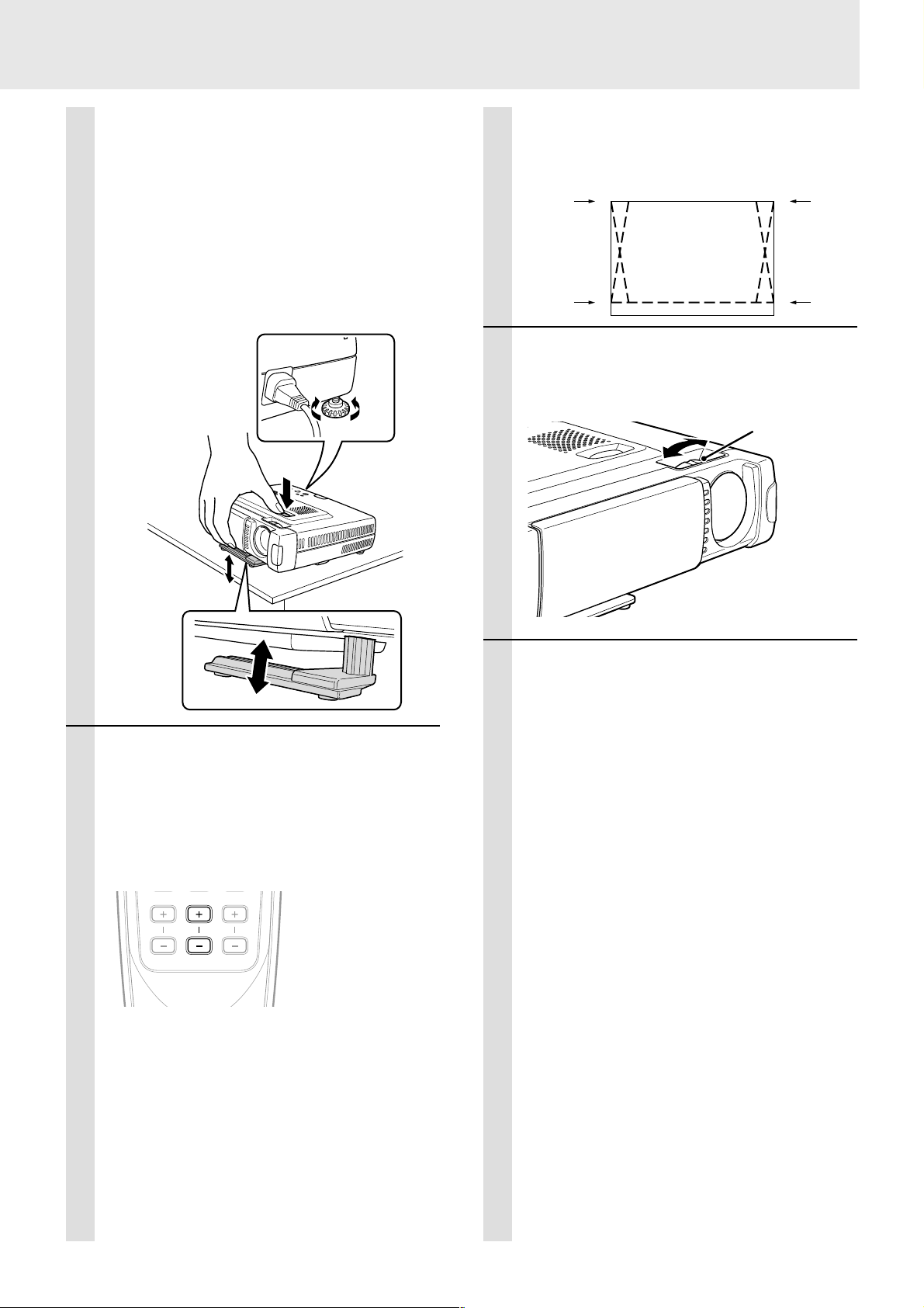
Adjuster Adjustment
There are two adjusters: one on the right side of the back panel
and another in the front center of the main unit.
1Use right hands to lift the front of the main unit to approxi-
mately the desired adjustment angle.
2Press the adjuster button on the front.
Loosen the adjuster legs and allow them to drop into position.
3Release the button.
The extended adjuster legs will be locked.
4Rotate the contact surfaces of the rear adjuster either clock-
wise or counterclockwise to accurately adjust the level.
4
The top and bottom of the projected image is
corrected, as shown below.
If a menu is being displayed, distortion of the
menu will not be corrected.
7 Adjust the image siz e to match the dis-
tance to the screen. Next, use the focus
ring to adjust the focus.
Down
1
Up
2
3
Up
Down
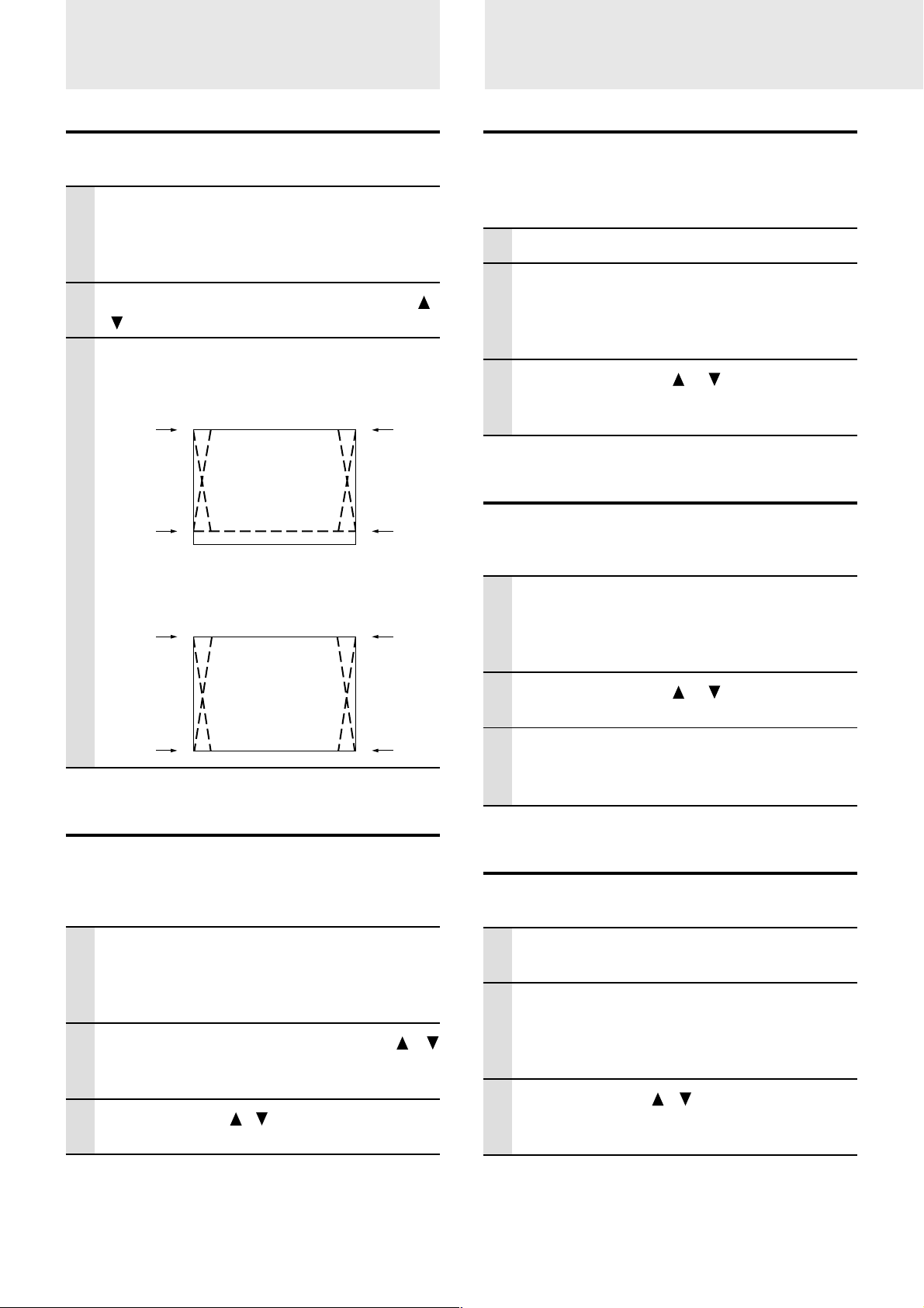
6 When distor tion of the projected image
cannot be corrected with the adjusters,
press the KEYSTONE +/– buttons of the
remote control to fine adjust (see page
18).
Using KEYSTONE to adjust projected image
distortion.
ZOOM VOLUMEKEYSTONE
Focus ring
8 Change the unit setting to suit the
method and source selected in step 4.
• Select the “PROJECTION” appropriate
for the type of projector installation.
(See page 29)
If the image is projected reversed, v ertically, or
horizontally, reset “PROJECTION”.
• In the case of video or S-video, select
the color system as necessary. (See
page 26)
Normally, it is not necessary to change the
factory settings. Also , set the RGB/YCbCr connector for component video (YCbCr). (See
page 27)
Note
Maximum correction is 14 degrees (including optical correction).
E – 15
• In the case of RGB input, adjust the
video of the connected PC.
This projector automatically identifies the input
signal and selects the most appropriate resolution.
However, manually adjust the “PICTURE ADJ”
and “FINE PICTURE” (see page 24) when there
is flicker, noise, color offset, etc., and manually
adjust the vertical and horizontal position (see
page 24) when the image is not centered.
You can also choose to project the image at the
original size of the incoming signal resolution.
(see page 27). (Normally, the resolution is automatically sensed and the display is enlarged
or reduced.)
(Continued on the next page.)
Page 18
T
Using the unit
Using the Remote Control
(continued)
9 Adjust the picture elements (see page
22), then select the picture type
according to the video content (see page
26).
10
Start using the unit.
The following functions are a vailable while using
the unit:
• Adjusting the volume of the unit's speaker
(see pages 18 and 28),
• Turning off the image and muting the sound
temporarily (see page 18),
• Freezing a moving picture (see page 18),
• Enlarging the picture (see page 19)
Note
• When there is no signal input for a period of 5 min. or more,
the power is automatically turned off and standby status is
activated. (see page 29)
After using the unit
(Input Selection)
MOUSE POWER
MENU
VIDEO button RGB button
VIDEO
CANCEL
RGB
Operating from the main unit
Inputs can be selected not only by operating the remote
control but also by using the main unit SOURCE button.
POWER STATUS
POWER SOURCE AUTO
SOURCE button
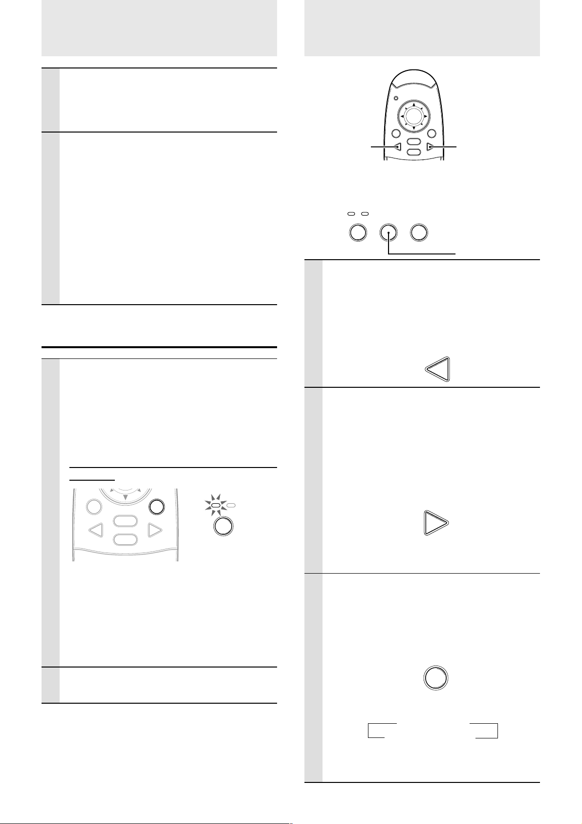
1 Press the VIDEO button.
The video signal (VIDEO, S-VIDEO) connected
to the input jack of this device will be detected
and projected automatically. If a video signal is
not detected, the message NO SIGNAL will be
displayed.
VIDEO
1 Press the POWER button of the remote
control or the PO WER button of the main
unit for a few seconds.
The power will turn off and the POWER indicator
will blink amber for 1 min., then the standby
status will be activated. (The exhaust fan will
continue to run for a while for cooling purposes.)
Do not unplug the power cord while the indicator
is blinking.
MOUSE POWER
VIDEO
Note
• The POWER switches of the remote control and main unit
will not operate until the blinking stops.
• After the standby status is activated, wait 1 min. or more
before turning the power on again. The power will not turn
on until the 1 min. interval has elapsed.
• The exhaust fan will continue to run even in standby status.
MENU
RGB
CANCEL
POWER S
POWER
Blinks amber
(1 min.)
↓
Lights amber
2 Press the RGB button.
The analog RGB signal connected to the input
connector of this device will be detected and
projected automatically.
(Component video will be detected if the RGB/
YCbCr connector is set (page 27) to YCbCr.) If a
video signal is not detected, the message NO
SIGNAL will be displayed.
RGB
Note
• All video signals input to this device will be detected if Auto
Source (page 29) is set.
3 Press the SOURCE button.
The video signal (RGB or YCbCr, VIDEO, SVIDEO) connected to the input jack of this device
will automatically be detected and projected. If a
video signal is not detected, the message NO
SIGNAL will be displayed.
SOURCE
2 Disconnect the power cord.
The POWER indicator will turn off.
The signals are sensed repeatedly in the sequence shown below.
→ RGB/YCbCr
S-VIDEO ← VIDEO
Note
• When Auto Source (see page 29) is set to ON, all signals
input to this projector will be sensed.
E – 16
Page 19
Using the Remote Control as the PC
Mouse
The remote control of this projector can be used as the PC mouse (wireless mouse function) by connecting the MOUSE connector of this
projector and the PC.
Remote control mouse functions
• The cursor key on the remote control operates the computer mouse functions.
• If a computer running Windows is connected, the ENTER button on the remote control operates
as the computer mouse left click button and the CANCEL button as the computer mouse right
click button.
• If a Macintosh computer is connected, the ENTER and CANCEL buttons operate in the same way
as the computer mouse click button.
Connecting a PC and the MOUSE connector of this projector
Before connecting a PC
• Before connecting, turn off the PC power. Turn off the power of this projector if it is on.
• When connection is completed, turn on the power of this projector and then start the PC.
USB Port Connection
Connect the supplied USB mouse cable directly to the USB
port (universal serial bus) of the personal computer, as
shown in the diagram.
Personal computer
USB port
MOUSE button
MOUSE POWER
MENU
VIDEO
CANCEL
IBM PC/AT or
Macintosh
RGB
MOUSE connector
IBM PS/2 Mouse Port Connection
Connect the supplied PS/2 mouse cable to the personal
computer, as shown in the diagram.
USB mouse cable (accessory)
AUDIO MOUSE RGB
/
YCbCr
VIDEOS-VIDEO
PS/2 mouse cable (accessory)
To PS/2 MOUSE
port
IBM PS/2 compatible
Note
• Depending on the personal computer, the mouse may not be recognized in some cases if not connected to the MOUSE connector before the personal
computer power is turned on.
• In the case of some notebook and laptop type personal computers, it may not be possible to use the standard pointing device (track ball, etc.) of the
personal computer when connected to the MOUSE connector. In such case, it will not be possible to use the pointing device until the personal
computer is rebooted, even if disconnected from the MOUSE connector.
E – 17
Page 20
Various functions while using the unit
The following operations can be performed by opening the FLIP COVER of the remote control.
FREEZE button
AUTO button
ZOOM +/– button
Automatic Screen Adjustment
Press the AUTO button.
AUTO
The position and size of the input image will be
adjusted automatically in accordance with the
resolution.
Note
Operation is the same as with the AUTO button of the main unit.
Freezing animated images
You can capture the desired frame of a moving picture.
Press FREEZE button.
A still image of the current frame is display ed. To
restore the present picture, press the button
again.
AUTO FREEZE MUTE
ZOOM VOLUMEKEYSTONE
MUTE button
VOLUME +/– button
KEYSTONE +/– button
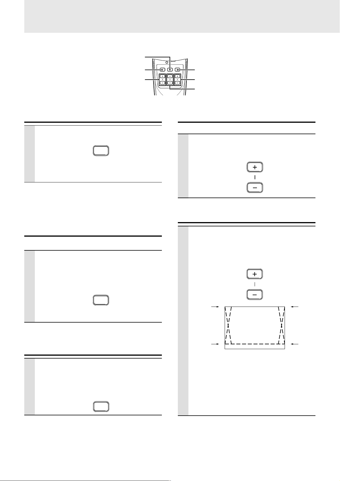
Adjusting the Volume
Adjusting the volume of the unit's speaker.
Press VOLUME + to increase the volume
or – to decrease.
VOLUME
KEYSTONE Adjustment
When distortion of the projected image
cannot be compensated with the adjusters, press the KEYSTONE +/– button to
adjust accurately.
KEYSTONE
FREEZE
Tip
The still picture can also be enlarged (see page 19).
Turning off the image and muting the
sound temporarily
Press MUTE button.
The image turns off and the sound is muted at the
same time. To restore the picture and sound,
press the button again.
MUTE
Using KEYSTONE button to adjust the top and
bottom of a projected image.
The top and bottom of the projected will be compensated, as
shown in the diagram. If the menu is displayed, distortion of
the menu itself will not be compensated.
Note
When keystone adjustment is used, whether or not the aspect
ratio of the image is to be maintained can be set from the menu
(see page 28).
E – 18
Page 21
To move to the desired portion of the
enlarged picture
Cursor key
ZOOM +/– button
MOUSE POWER
MENU
VIDEO
CANCEL
AUTO FREEZE MUTE
ZOOM VOLUMEKEYSTONE
RGB
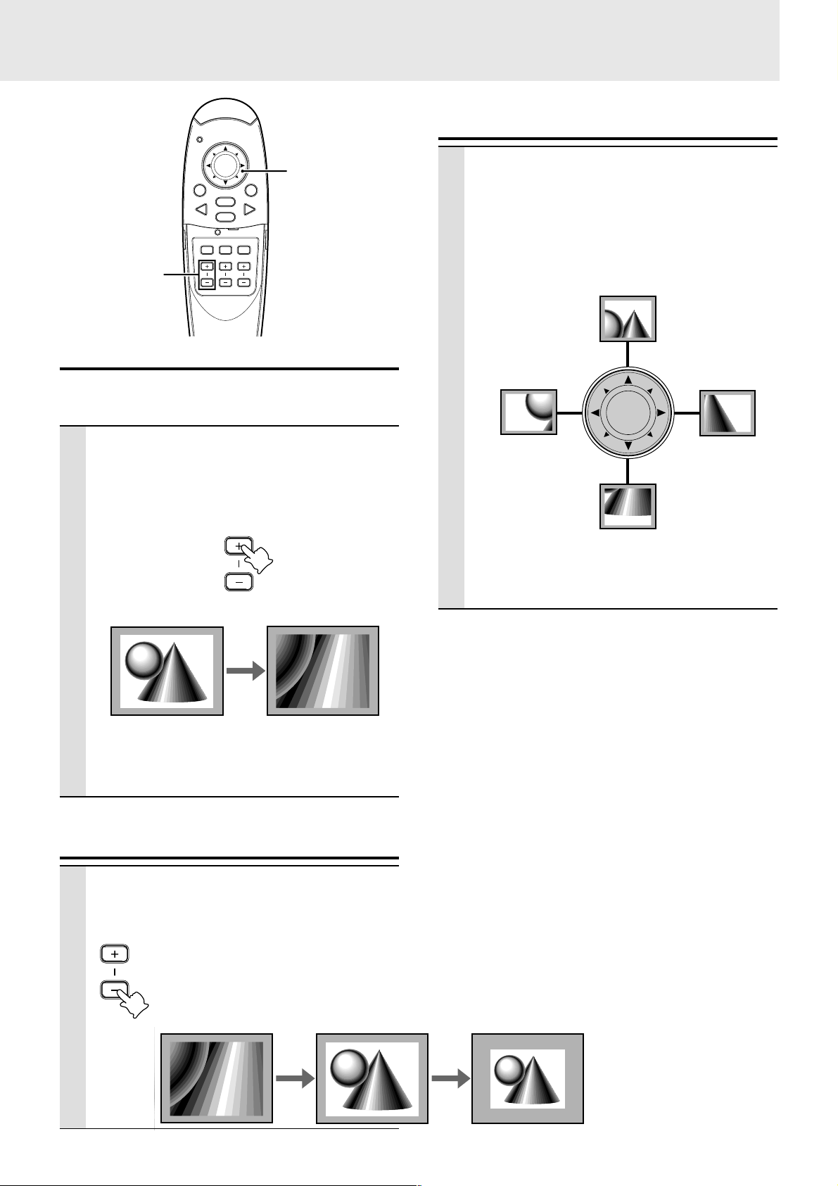
Enlarging the picture
You can enlarge the picture up to ten times the original
size.
Press ZOOM + button.
While the button is pressed the picture is enlarged until it becomes ten times the original size.
Release the button at the desired size.
ZOOM
Original size
Ten times as large as
the original size
Press the desired portion of the cursor
key.
The available directions are indicated b y the four
large triangle marks on the cursor key. The picture will move in the direction of the mark you are
pressing.
Move upward
Move leftward
Move downward
Note
Less than the original size of the picture cannot be moved
because the whole image is fully displayed.
Move rightward
Note
The quality of the enlarged picture deteriorates compared to
the original size picture.
Screen Reduction
Press ZOOM – button. When this button is
released, the screen will return to 90%
reduction.
ZOOM
Enlarged screen Standard screen
90% reduction
screen
E – 19
Page 22
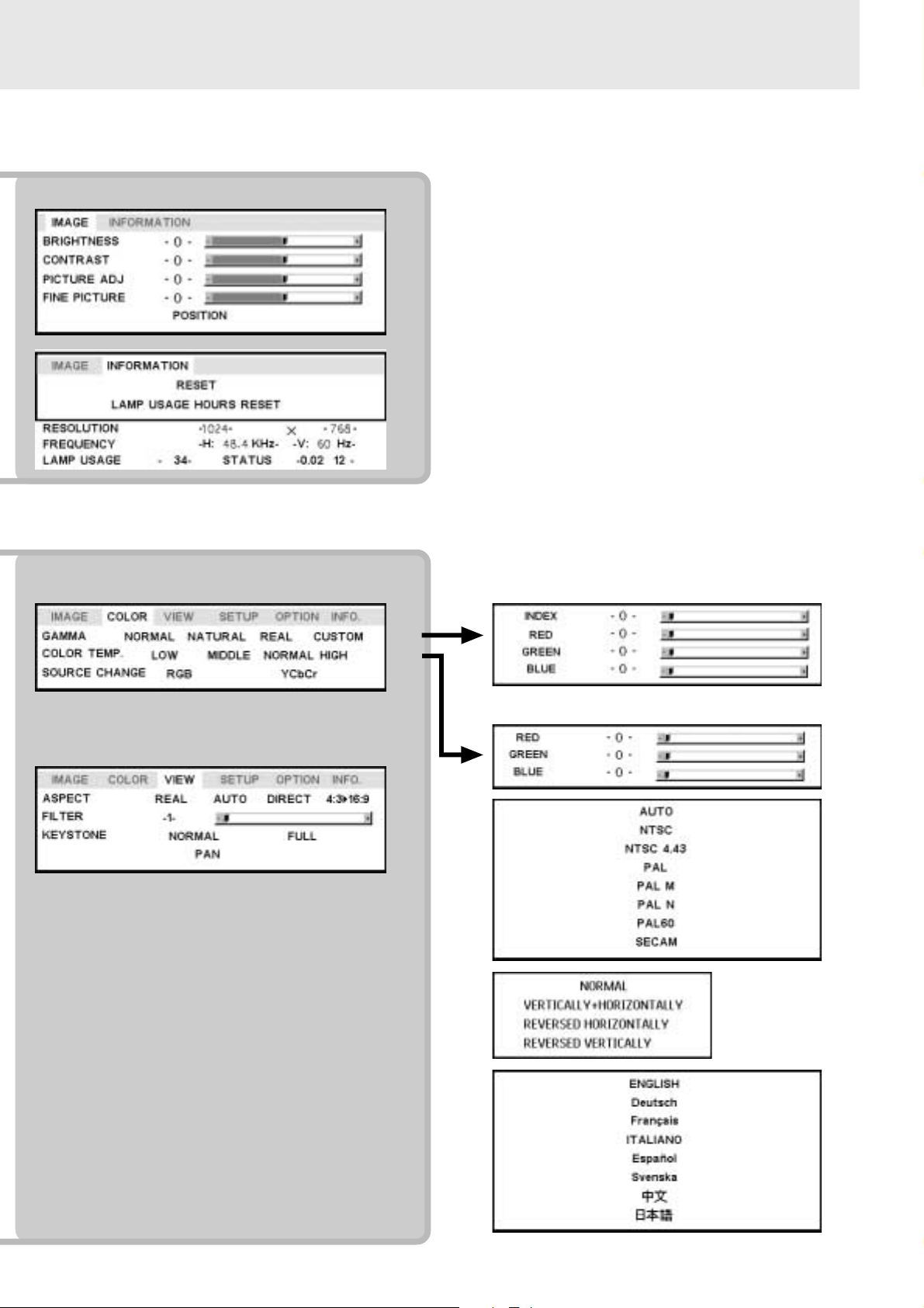
Menu operation
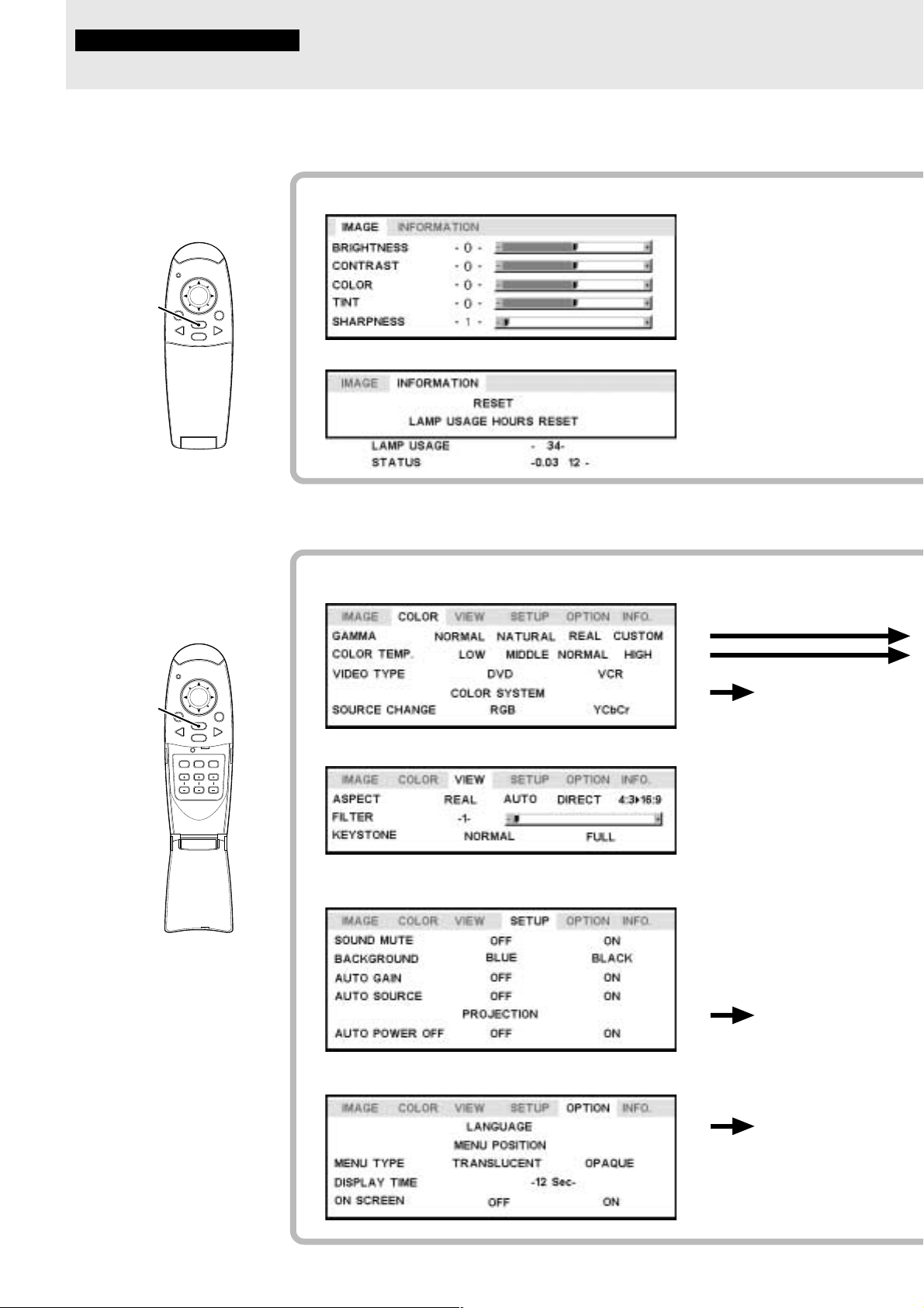
Menu Structure
The numerals in parentheses ( ) are reference page numbers.
The normal menu will be
displayed when the MENU
button is pressed with the
remote control FLIP COVER
closed.
MENU button
MOUSE POWER
MENU
VIDEO
RGB
CANCEL
PLUS
Normal menu
For VIDEO, S-VIDEO and component video (YCbCr) input
(22)
(22)
(22)
(22)
(22)
(25)
(25)
The advanced menu will be
displayed when the MENU
button is pressed with the
remote control FLIP COVER
open.
MENU button
MOUSE POWER
MENU
VIDEO
RGB
CANCEL
AUTO FREEZE MUTE
ZOOM VOLUMEKEYSTONE
Advanced menu
For VIDEO, S-VIDEO and component video (YCbCr) input
Common menu
(26)
(26)
(26)
(26)
(27)
(27)
(27)
(28)
(28)
(28)
(28)
(29)
(29)
(29)
Å
ı
Common menu
E – 20
(30)
(30)
(30)
(30)
(30)
Ç
Page 23
Normal menu
RGB input
(22)
(22)
(24)
(24)
(24)
(25)
(25)
Advanced menu
• The Advanced menu cannot be used unless the FLIP COVER of the supplied remote control is open.
RGB input
(26)
(26)
(27)
(27)
(27)
(28)
(28)
Å
ı
(26)
(26)
(26)
(29)
Ç
E – 21
(30)
Page 24
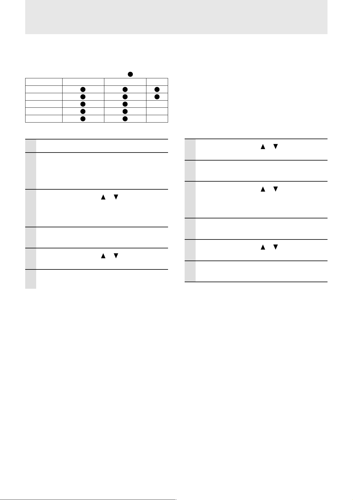
Adjusting the picture elements
The picture elements such as brightness, contrast, white
balance, and so on can be adjusted individually for each
input source. The adjustable items vary depending on the
input source.
(The elements marked with “ ” are adjustable.)
Input source
BRIGHTNESS
CONTRAST
COLOR –
TINT –
SHARPNESS
VIDEO/S-VIDEO CONPONENT VIDEO RGB
–
For VIDEO, S-VIDEO and component video
(YCbCr) input.
1 Select the input source (see page 16)
2 Press the MENU button to display the
menu, hold do wn the cursor 씱 / 씰 keys or
the MENU button and then select “IMAGE”.
3 Press the cursor / keys to select
“BRIGHTNESS”.
The items that appear in the menu will differ
depending on the input.
4 Press the cursor 씱 / 씰 keys to adjust the
brightness.
5 Press the cursor / keys to select
“CONTRAST”.
6 Press the cursor 씱 / 씰 keys to adjust the
contrast.
7 Press the cursor / keys to select
“COLOR”.
8 Press the cursor 씱 / 씰 keys to adjust the
color.
9 Press the cursor / keys to select
“TINT”.
Note
This adjustment is not possible with the SECAM color system.
10
Press the cursor 씱 / 씰 keys to adjust the
tint.
11
Press the cursor / keys to select
“SHARPNESS”.
12
Press the cursor 씱 / 씰 keys to adjust the
sharpness.
E – 22
To close the menu
Press the CANCEL button.
Page 25
Adjusting the projected image from
the computer
The unit selects the most suitable resolutions as shown in the “Timing Chart” belo w according to the incoming signals from the RGB/YCbCr
connector. However, you may need manual adjustment depending on the computer. If you have any vertical banding, noise, dot interference,
or crosstalk on the projected picture, adjust the clock frequency with “PICTURE ADJ” then the clock phase with “FINE PICTURE” (see page
24). You can also adjust the horizontal and vertical position of the image (see page 24).
When adjusting manually, you can choose to project the image at the or iginal size of the incoming signal resolution (see page 27). (Normally,
the image is enlarged or reduced to the most suitable size automatically.)
Timing Chart
Resolution H Sync. (kHz) V Sync. (Hz)
IBM PC/AT compatible machine 640 × 350 31.5 70.1
640 × 350 37.9 85.1
720 × 350 31.5 70.0
640 × 400 31.5 70.1
640 × 400 37.9 85.1
720 × 400 31.5 70.0
720 × 400 37.9 85.0
640 × 480 31.5 60.0
640 × 480 37.9 72.8
640 × 480 37.5 75.0
640 × 480 43.3 85.0
800 × 600 35.2 56.3
800 × 600 37.9 60.3
800 × 600 46.9 75.0
800 × 600 48.1 72.2
800 × 600 53.7 85.1
1024 × 768 48.4 60.0
1024 × 768 56.5 70.1
1024 × 768 58.1 72.0
1024 × 768 60.0 75.0
1024 × 768 68.7 85.0
1280 × 1024 64.0 60.0
1280 × 1024 80.0 75.0
1280 × 1024 91.1 85.0
Apple Macintosh 640 × 480 35.0 66.7
832 × 624 49.7 74.5
1024 × 768 60.2 74.9
1152 × 870 68.7 75.6
1280 × 1024 81.1 76.1
Sun 1152 × 900 61.8 66.0
1280 × 1024 74.9 69.9
1280 × 1024 81.1 76.1
SGI 1024 × 768 49.7 60.4
1280 × 1024 63.9 60.0
1152 × 900 71.7 76.1
HP 1280 × 1024 78.1 72.0
(U3-1080)
The resolution of the unit is 1024 × 768. Other resolution images (e.g. 1280 × 1024) are compressed into 1024 × 768. In such a case, projected letters
and lines might appear unevenly.
(U3-880)
The resolution of the unit is 800 × 600. Other resolution images (e.g. 1024 × 768) are compressed into 800 × 600. In such a case, projected letters
and lines might appear unevenly.
E – 23
Page 26
Manual Adjustment of Personal
Computer Images
Adjusting Clock Frequency and Phase
1 Select RGB as the input (page 16).
2 Press the MENU button to display the
main menu and then press the cursor 씱 /
씰 keys to select the “IMAGE”.
3 Press the cursor / keys to select the
“PICTURE ADJ”.
4 Press the cursor 씱 / 씰 keys and adjust
the image width in relation to the screen.
Adjustment is performed in dot units. Adjust to
the position where vertical flicker disappears.
5 Press the cursor / keys and select
“FINE PICTURE”.
6 Press the cursor 씱 / 씰 ke ys and adjust to
minimize image noise, flicker, color variations, etc.
Adjusting the position of the image
If the image is offset up, down, left or right, adjust the
vertical and horizontal position.
1 Perform steps 1 - 6 for Adjusting the
Clock Frequency and Phase on this page.
2 Press the cursor / keys and select
“POSITION”.
3 Press the cursor / , 씱 / 씰 keys and
adjust the horizontal and vertical position.
Reconnecting a separate personal computer or
other device to the RGB jack
Either press the AUTO button on the main unit or open the FLIP
COVER of the remote control and press the AUTO button there.
If no images appear during setting
Use the following procedure when no images appear during setting
because the clock frequency or phase is grossly inaccurate.
1 Turn off the power of all devices connected.
The input signal will stop and either a blue or black background
(This depends on the Background setting. page 28) will be
projected.
2 Perform a reset (page 25).
3 Readjust the picture ADJ and fine picture
E – 24
To close the menu
Press the CANCEL button.
Page 27
Resetting the Lamp
Resetting
Resetting
All items can be reset to the standard settings except as
follows.
• Lamp usage time
• KEYSTONE adjustment values (including the KEY-
STONE setting value: page 28).
1 Press the remote control MENU button to
display the normal menu and then press
the cursor 씱 / 씰 keys to select “INFOR-
MATION”.
2 When the INFORMATION menu appears,
press the cursor / keys select “RESET”, then press the ENTER button.
3 If the ENTER button is not used during
reset, press the CANCEL button.
Hours of Usage
Resetting the time the hours of lamp
usage
When the lamp is replaced (page 33), it is necessary to set
the lamp hours of usage from the menu.
1 Press the remote control MENU button,
use the cursor 씱 / 씰 keys to display the
“INFORMATION” menu and set the lamp
hours of usage.
2 Display the INFORMATION men u, use the
cursor / keys to select “LAMP USAGE
HOURS RESET” and then press the ENTER button.
3 If the ENTER button is not used during
reset, press the CANCEL button.
When the power will not turn on because
the lamp usage hours of has exceeded
1100 hours
The power will not turn on when the lamp hours of usage
has exceeded 1100 hours. The status light will be on
continually (page 32). Thus, the menu cannot be displayed.
In such case, replace the lamp housing, then use the
following procedure to reset.
1 Connect the power cord (page 14).
Standby status will be activated.
2 Press the SOURCE and AUTO buttons of
the main unit at the same time for 5 sec. or
more.
The lamp hours of usage will be reset. After
resetting, the Status indicator (page 32) that
turned on because 1100 hours had been exceeded will turn off.
E – 25
To close the menu
Press the CANCEL button.
Page 28
Setting Narrow Images (Advanced
Menu)
Set the colors as desired in accordance
with the image contents.
Subtle color settings are possible, as desired. Setting is
possible for each input.
1 Select the image to be input (page 16).
2 With the FLIP COVER of the remote con-
trol open, press the MENU button to display the Advanced menu, then use the
cursor 씱 / 씰 keys to select “COLOR”.
3 Use the cursor / keys to select
“GAMMA”.
4 Use the cursor 씱 / 씰 keys to set the
“GAMMA”.
The following can be selected.
● Normal ● Natural ● Real ● Custom
Normal is standard settings; Natural stresses
coloring; Real stresses (brightness). Custom is
used to adjust freely as desired.
5 Use the cursor 씱 / 씰 keys to select “CUS-
TOM”, press the ENTER button to displa y
the sub-menu and then set the gamma
value. There are 33 index values.
Setting the Video Type
1 With the FLIP COVER of the remote con-
trol open, press the MENU button to display the Advanced menu, then use the
cursor 씱 / 씰 keys to select “COLOR”.
2 Use the cursor / keys to select
“VIDEO TYPE”.
3 Use the cursor 씱 / 씰 keys to set the
“VIDEO TYPE”.
The following can be selected.
● DVD ● VCR
D VD is used for DVD players and VCR is used f or
normal video players.
Selecting the Color System
The following color systems can be used with this device.
● NTSC 3.58 ● NTSC 4.43
● PAL ● PAL-M ● PAL-N ● PAL60
● SECAM
Only NTSC 3.58 and PAL can be used for component
video.
Selection is automatic when AUTO is used.
Adjusting Color Balance
Color balance (white balance) can be set for each input.
1 Select the image to be input (page 16).
2 With the FLIP COVER of the remote con-
trol open, press the MENU button to display the Advanced menu, then use the
cursor 씱 / 씰 keys to select “COLOR”.
3 Use the cursor / keys to select
“COLOR TEMP”.
4 Use the cursor 씱 / 씰 keys to select the
“COLOR TEMP”.
Four different types of color balance can be set
beforehand: Low, Medium, Standard and High.
When the ENTER button is pressed, the
sub-menu will be displayed to enable fine
adjustment.
1 Select an input for the color system to be
selected (page 16).
2 With the FLIP COVER of the remote con-
trol open, press the MENU button to display the Advanced menu, then use the
cursor 씱 / 씰 keys to select “COLOR”.
3 Use the cursor / keys to select
“COLOR SYSTEM” and then press the
ENTER button.
4 Use the cursor / keys to select the
desired color system.
E – 26
To close the menu
Press the CANCEL button.
Page 29
Setting in Accordance
With Image Contents
Setting the RGB/YCbCr connector
The RGB/YCbCr connector can be switched and used as
the component video signal (YCbCr) input connector.
1 With the FLIP COVER of the remote con-
trol open, press the MENU button to display the Advanced menu, then use the
cursor 씱 / 씰 keys to select “COLOR”.
2 Use the cursor / keys to select
“SOURCE CHANGE”.
3 Use the cursor 씱 / 씰 keys to set the
“SOURCE CHANGE”.
The following can be selected.
● RGB ● YCbCr
When component video (YCbCr) input is used,
use the optional component video cable.
Setting the Display Frame
The display frame can be set individually for each input.
1 Select the input for image selection (page
16).
2 With the FLIP COVER of the remote con-
trol open, press the MENU button to display the Advanced menu, then use the
cursor 씱 / 씰 keys to select “VIEW”.
3 Display the frame, then use the cursor /
keys to select “ASPECT”.
4 Use the cursor 씱 / 씰 keys to set the
“ASPECT” ratio.
Any of the following four different settings can be
selected for images.
●REAL (input signal projection without pixel replacement)
●AUTO (projection after automatic input signal
zoom in/zoom out)
●DIRECT (the original aspect ratio of the image
is maintained at all times)
●4:3 → 16:9 (4:3 aspect ratio images are pro-
jected after conversion to 16:9 aspect ratio)
Setting Filter
This is used to set the sharpness during pixel conversion
(image compression/enlargement).
1 With the FLIP COVER of the remote con-
trol open, press the MENU button to display the Advanced menu, then use the
cursor 씱 / 씰 keys to select “VIEW”.
2 Display the frame, then use the cursor /
keys to select “FILTER”.
3 Use the cursor 씱 / 씰 keys to set the
sharpness.
E – 27
To close the menu
Press the CANCEL button.
Page 30
Setting in Accordance With
Image Contents (continued)
Setting Keystone
This is used to set the height for keystone adjustment.
Initial Settings
Audio Muting
Audio only can be muted for each input.
This function is convenient when multiple video units are
connected to this projector.
1 With the FLIP COVER of the remote con-
trol open, press the MENU button to display the Advanced menu, then use the
cursor 씱 / 씰 keys to select “VIEW”.
1 Select the input to be muted (page 16).
2 With the FLIP COVER of the remote con-
2 Display the frame, then use the cur sor /
keys to select “KEYSTONE”.
3 Use the cursor 씱 / 씰 keys to select “NOR-
MAL” or “FULL”.
●Normal: normal keystone correction
3 Use the cursor / keys to select
Selecting the Background
Two different backgrounds can be selected for projection
when there is no signal input.
trol open, press the MENU button to display the Advanced menu, then use the
cursor 씱 / 씰 keys to select “SETUP”.
“SOUND MUTE”, then use the cursor 씱 /
씰 keys to set muting to ON or OFF.
●Full: In this mode, the image is enlarged to fill
the screen vertically and then Keystone correction is performed.
Setting the partial display position
Input a signal that is rated SXGA (XGA for the U3-880) to
RGB/YCbCr connector and then set the partial display
position with ASPECT (described later) set to Real.
1 With the FLIP COVER of the remote con-
trol open, press the MENU button to display the Advanced menu, then use the
cursor 씱 / 씰 keys to select “VIEW”.
2 Display the frame, use the cursor /
keys to select “PAN” and then press the
ENTER button.
3 Use the cursor / , 씱 / 씰 keys to set the
display position.
1 With the FLIP COVER of the remote con-
trol open, press the MENU button to display the Advanced menu, then use the
cursor 씱 / 씰 keys to select “SETUP”.
2 Use the cursor / keys to select
“BACKGROUND”.
3 Use the cursor 씱 / 씰 keys to select one of
the following backgrounds.
● Blue ● Black
Auto Gain
Brightness and contrast are adjusted automatically.
1 Select the input to be set for auto gain
(page 16).
2 With the FLIP COVER of the remote con-
trol open, press the MENU button to display the Advanced menu, then use the
cursor 씱 / 씰 keys to select “SETUP”.
3 Use the cursor / key to select “AUTO
GAIN”, then use the cursor 씱 / 씰 ke ys to
set ON or OFF.
E – 28
To close the menu
Press the CANCEL button.
Page 31

Auto Source Settings
Using the Power Saving Function
Automatically Searching The Input Signal
1 With the FLIP COVER of the remote con-
trol open, press the MENU button to display the Advanced menu, then use the
cursor 씱 / 씰 keys to select “SETUP”.
2 Use the cursor / keys to select “AUTO
SOURCE”, then use the cursor 씱 / 씰
keys to set ON or OFF.
ON: All input signals are searched.
OFF: Remote control VIDEO button:
Video and S-video are searched.
Remote control RGB button:
RGB and YCbCr signals are searched.
Main unit SOURCE button:
All input signals are searched individually.
Selecting a Projection Type
If the projection type is not correctly set in accordance with the
installation conditions, images may be projected reversed, vertically, or horizontally.
When there is no signal input for a period of 5 min. or
more, the power is automatically turned off and standby
status is activated.
1 With the FLIP COVER of the remote con-
trol open, press the MENU button to display the Advanced menu, then use the
cursor 씱 / 씰 buttons to select “SETUP”.
2 When SETUP menu is displayed, use the
cursor / keys to select “AUTO
POWER OFF”.
3 Use the cursor 씱 / 씰 keys to set Power
Saving to ON or OFF.
1 With the FLIP COVER of the remote con-
trol open, press the MENU button to display the Advanced menu, then use the
cursor 씱 / 씰 keys to select “SETUP”.
2 When SETUP menu is displayed, use the
cursor
TION”, then press the ENTER button.
/ keys to select “PROJEC-
3 Use the cursor / keys to select a
projection type in accordance with the
set conditions.
The setting items will change as shown below
each time a key is pressed.
Normal ⇔
⇔
Reversed vertically ⇔ Reversed horizontally
Reversed vertically+horizontally
⇔
E – 29
To close the menu
Press the CANCEL button.
Page 32

Setting the Menu
Selecting a Menu Language
Any one of eight different languages can be selected for
menu displays.
1 With the FLIP COVER of the remote con-
trol open, press the MENU button to display the Advanced menu, then use the
cursor 씱 / 씰 keys to select “OPTION”.
2 When OPTION menu is display ed, use the
cursor / keys to select “LANGUAGE”,
then press the ENTER button.
3 Use the cursor / keys to select one of
the following languages.
●English
●German
●French
●Italian
●Swedish
●Spanish
●Chinese
●Japanese
Menu Viewing Settings
The menu viewing method can be set with this function.
1 With the FLIP COVER of the remote con-
trol open, press the MENU button to display the Advanced menu, then use the
cursor 씱 / 씰 keys to select “OPTION”.
2 When OPTION menu is displayed, use the
cursor / keys to select “MENU TYPE”.
3 Use the cursor 씱 / 씰 keys to select
“TRANSLUCENT” or “OPAQUE”.
Other Menu Settings
The time that the menu is displayed on the screen can be
set with this function.
1 With the FLIP COVER of the remote con-
trol open, press the MENU button to display the Advanced menu, then use the
cursor 씱 / 씰 keys to select “OPTION”.
Setting the Menu Display Position
The menu display position can be set with this function.
1 With the FLIP COVER of the remote con-
trol open, press the MENU button to display the Advanced menu, then use the
cursor 씱 / 씰 keys to select “OPTION”.
2 When OPTION menu is display ed, use the
cursor
TION” and then press the ENTER button.
/ keys to select “MENU POSI-
3 Use the cursor / , 씱 / 씰 keys to set the
display position.
2 When OPTION menu is displayed, use the
cursor / keys to select “DISPLAY
TIME”.
3 Use the cursor 씱 / 씰 keys to set a value
from 5 sec. to 30 sec.
On-screen Display
This function is set to ON at the factory. When set to ON,
input will be projected onto the screen when the input is
switched with the remote control button. Also, the Input
menu will be displayed when the power is turned on to
indicate the selected input. In addition, status is displayed
on the menu bar when FREEZE, MUTE, ZOOM, KEYSTONE or VOLUME is set.
1 With the FLIP COVER of the remote con-
trol open, press the MENU button to display the Advanced menu, then use the
cursor 씱 / 씰 keys to select “OPTION”.
2 When OPTION menu is displayed, use the
cursor
/ keys to select “ON SCREEN”.
3 Use the cursor 씱 / 씰 keys to set ON or
OFF.
To close the menu
E – 30
Press the CANCEL button.
Page 33

Others
Troubleshooting
Please check the following before requesting repairs.
Symptom
The power will not turn on.
No image
Procedure
• Is the power plug connected to the power outlet?
• Is the lamp cover correctly installed?
• Is the internal temperature too high? A protective feature prevents the
power turning on when the internal temperature is too high.
• Has the lamp usage time exceeded 1100 hours? The power will not turn
on when 1100 hours have elapsed.
• Any high-tension noise to the power line with extremely high pulse can
stop the projector. If it happens, unplug the power cord from the outlet
once and then plug it again.
• Has the connected input been selected?
• Is the cable correctly connected to the input jack?
• Are the brightness and contrast set to minimum?
• Is the sliding lens cap closed?
• Is the lamp blown?
• Has the lamp usage time exceeded 1100 hours?
• If a notebook type computer is being used, was the computer power turned
on after the projector was connected? Is the computer set to disable output to the external RGB jack?
In many cases, when a notebook type computer is connected to the projector, a signal will not be output to the RGB OUT jack unless the computer power is turned on.
• Does the STATUS indicator blink?
Reference page
14
33
32
25, 32, 33
16, 18
10, 11, 12
22
14
33
25, 32, 33
12, 13
32
Distorted images
Blurred images
Images are offset vertically or
horizontally and are not
correctly displayed
The remote control does not
work
The wireless mouse does not
work
The STATUS indicator blinks
• Is installation correct?
• Was the Keystone adjustment performed correctly?
• Is the lens properly focused?
• Are the screen and projector positioned at the correct angle?
• Does the projection distance place the screen outside the focus range?
• Is there condensation, dirt, etc., on the lens?
Condensation on the internal optical system is possible when the projector has been stored in a cool place and then is used in a warm place. In
such cases, wait several minutes for the condensation to evaporate.
• Correctly adjust the horizontal and vertical position of the screen.
• Is the clock frequency correctly adjusted?
• Are the resolution and frequency correct for the input signal? Check the
resolution of the personal computer.
• Does the send indicator (LED) light? If it does not light, the batteries are
exhausted. In such cases, replace with fresh batteries.
• Is there any obstacle between the remote control and the photoreceptor
of the main unit?
• Is the remote control being used outside its effective range?
• Is there a fluorescent light or other str ong light sour ce close to the photoreceptor?
• Is the MOUSE jack of the main unit and the personal computer correctly
connected?
• Was the personal computer started after being connected to the MOUSE
jack of the main unit?
• Check the STATUS indicator list.
14
18, 28
15
14
9
—
24
24
23
5, 8
5
5
—
17
17
32
Flickering text or offset colors
with RGB input
• Manually adjust the clock frequency and phase.
• Press the AUTO button.
E – 31
24
Page 34

When the STATUS indicator lights or flashes
STATUS indicator
POWER STATUS
POWER SOURCE AUTO
Status Light Messages
Condition
OFF
On Continually
Flashing Very Rapidly (On and off
in a cycle of 1 sec.)
Flashing Rapidly
(On and off in a cycle of 4 sec.)
Status
Normal
The lamp usage has exceeded 1000 hours of operation and should be replaced.
• The lamp cover is not correctly attached. Replace it correctly.
• The temperature protector has been triggered. If the room temperature is high,
move the unit to a cool location. If the temperature within the unit is high, chec k the
cooling fan ventilation slots and the ventilation slots on the bottom of the unit. If
any of the slots are blocked, remove whatever is blocking them.
• The temperature protector has been trigg er ed. If you try to turn on the unit immediately after turning off, sometimes the power does not come on. If this happens, wait
at least one minute, then turn on the unit again.
• The lamp lighting voltage error detection protector has been triggered. Wait at
least one minute before turning on the unit again. If this does not solve the problem,
please contact your dealer.
Flashing Slowly (On and off in a
cycle of 8 sec.)
Flashing Very Slowly (On and off in
a cycle of 12 sec.)
The cooling fan has stopped. Contact your PLUS dealer for service.
The lamp is not turned on.
• The unit was turned on immediately after being turned off. Turn off the unit, wait at
least one minute, then turn on the unit again.
• The lamp is dead. Replace the lamp cartridge. (See page 33.)
E – 32
Page 35

Replacing the lamp cartridge
The rated lamp life is about 1,000 hours. The rated lamp life is the average
life of the lamps produced and tested (under the test conditions of our
company) for a long term, however, it may become shorter depending on
the conditions of usage.
After the lamp has been operating for 1000 hours or longer, the STATUS
indicator on the control panel will light and the “LAMP USAGE” icon
which shows hours of total lamp usage will be displayed on the screen.
When this happens, turn off the unit and replace the lamp cartridge with a
new one. The unit will not turn on after 1100 hours. (It will go off if it is in
use.)
CAUTION
• DO NOT TOUCH THE LAMP immediately after it has been
used. It will be extremely hot. Allow at least one hour for the
lamp to cool before handling.
• DO NOT LOOSEN ANY SCREWS except for those mentioned in the instructions below. There is danger of electric
shock.
Lamp cartridge replacement procedure
1 Disconnect the power cable.
Wait at least one hour f or the lamp to cool.
2 Turn the unit upside down carefully.
3 Loosen the lamp cover securing screw.
4 Remove the lamp cover.
Step 3
Step 4
Step 5
Step 6
Lamp Cover
Lamp cartridge
CAUTION: Do not use a lamp cartridge other than the PLUS
replacement lamp cartridge. Order this from your PLUS dealer
using the unit model number (see “Notes” below).
5 Loosen the three lamp cartridge securing screws.
(This unit has a safety switch.)
6 Hold the handle then pull the lamp cartridge upward to remo v e
it.
7 Install the new lamp cartridge.
8 Secure the lamp cartridge with the three screws.
9 Replace the lamp cover and secure it with the securing screw.
10 Return the unit to the normal position, connect the po wer cable,
and turn on the unit.
11 Reset “LAMP USAGE.” (See page 25).
Notes
• When the lamp usage time reaches 1100 hours, it becomes impossible
to switch on the power and menus are not displayed. In such a case,
see “If the unit doesn’t go on because lamp usage exceeds 1100
hours” on page 25.
• Obtain a replacement lamp cartridge at the store where the unit was
purchased. Please specify the following information when ordering a
replacement lamp cartridge:
– Model name : U3-120
– Product code : 28-631
Step 7
Step 8
Step 9
E – 33
Page 36

Specifications
Optical
TM
DMD
Lens Manual focus fixed lens
Lamp High Performance Compact Lamp
Image Size 914 to 5080 mm (36 to 200 in.) diagonal
Projection Distance 1.2 to 6.8m (3.9 to 22.3 ft.)
Light Output 800 ANSI lumens (normally white)
Contrast Ratio 800 : 1
Electrical
Inputs Video (NTSC / PAL / PAL_M / PAL_N / PAL60 / SECAM / NTSC4.43)
Color Reproduction Full color, 16.7 million colors simultaneously.
Resolution (U3-1080)
Power Requirement 100 to 120/220 to 240 V AC, 50/60 Hz
Power Consumption 180 watts
Single Chip Digital Micro Device (DMDTM)
(U3-1080) (U3-880)
1024 × 768 dots 800 × 600 dots
F=3.0 f=23 mm
RGB (H:15 to 91 kHz, V: 50 to 85 Hz)
SXGA (Compression), XGA(True), SVGA/VGA (Expansion/True)
(U3-880)
XGA (Compression), SVGA (True), VGA (Expansion/True)
Mechanical
Dimensions Excluding Stand 23.0 cm (W) × 4.8 cm (H) × 17.7 cm (D) / 9.0 in.(W) × 1.9 in.(H) × 7.0 in.(D)
Net Weight 1.3 kg / 2.9 lbs
Operational Temperatures Data projector: 5° to 35°C (41° to 95°F), 30 to 85% humidity
Remote control: 0° to 60°C (32° to 140°F)
Regulations UL Approved (UL 1950, CSA 950)
Meets FCC Class A requirements
Meets EMC Directive (EN55022, EN55024)
Meets Low Voltage Directive (EN60950)
D-Sub Pin Assignments
PC 15-Pin mini D-Sub
Pin No.
1
2
3
4
5
6
7
8
9
10
11
12
13
14
15
Signal to be connected
Red
Green
Blue
GND
GND
Red GND
Green GND
Blue GND
No Connection
Digital GND
GND
SDA
Horizontal Sync
Vertical Sync
SCL
E – 34
Page 37

Dimensions
1.9″
11 mm/
0.4″
177 mm/7.0″
OPEN
POWER STATUS
230 mm/9.0″
POWER SOURCE AUTO
48 mm/
E – 35
1.1″
27 mm/
Page 38

MODE D’EMPLOI
U3-1080/U3-880
Français
Page 39

INFORMATIONS IMPORTANTES
RELATIVES À LA SÉCURITÉ
Précautions
Lisez attentivement ce manuel av ant d’utiliser le projecteur de données PLUS U3-1080/U3-880, et conservez-le à portée de main pour pouv oir
vous y reporter ultérieurement.
Le numéro de série se trouve près de l’interrupteur d’alimentation principal, sur le panneau arrière de l’appareil.
Inscrivez-le ici :
ATTENTION
POUR ÉVITER TOUT RISQUE DE CHOC ÉLECTRIQUE, NE PAS OUVRIR LE COFFRET. L’APPAREIL NE
RENFERME AUCUNE PIÈCE QUI SOIT RÉPARABLE PAR L’UTILISATEUR. CONFIER TOUTE
RÉPARATION À UN PERSONNEL QUALIFIÉ DE LA SOCIÉTÉ PLUS.
AVERTISSEMENT
POUR ÉVITER TOUT RISQUE DE FEU OU DE
CHOC ÉLECTRIQUE, NE PAS EXPOSER
L’APPAREIL À LA PLUIE NI À L’HUMIDITÉ. NE
PAS UTILISER LA FICHE AVEC MISE À LA
TERRE DE L’APPAREIL AVEC UNE
RALLONGE OU UNE PRISE SECTEUR SI LES
Danger d’explosion si la pile n’est pas remplacée
correctement. Remplacer uniquement par une
pile du même type ou d’un type équivalent
recommandé par le fabricant. Mettre les piles
usées au rebut en suivant les instructions du
fabricant.
ATTENTION
TROIS BROCHES NE PEUVENT PAS ÊTRE
TOUTES INSÉRÉES À FOND. NE PAS OUVRIR
LE COFFRET, CAR IL RENFERME DES
COMPOSANTS SOUS HAUTE TENSION.
CONFIER TOUTE RÉPARATION À UN PERSONNEL QUALIFIÉ DE LA SOCIÉTÉ PLUS.
Avertissement
Cet appareil est un produit de classe A. Dans un
environnement domestique, il risque de provoquer un
brouillage radio, auquel cas l'utilisateur peut être requis de
prendre les mesures adéquates.
Consignes de sécurité importantes
Ces consignes de sécurité ont pour but de garantir une longue durée de service de l’appareil et d’éviter le feu et les chocs électriques. Veuillez
les lire attentivement et observer tous les avertissements.
Installation
• Pour obtenir les meilleurs résultats, utilisez l’appareil dans une
pièce sombre.
• Placez l’appareil sur une surface plane et de niveau, dans un
endroit sec et loin de toute poussière et humidité.
• N’installez pas l’appareil en plein soleil, près d’un appareil de
chauffage ou d’un appareil dégageant de la chaleur.
• Toute exposition aux rayons du soleil, à la fumée ou à la vapeur
risque d’endommager les composants internes.
• Manipulez l’appareil avec précaution. Une chute ou un choc
risquent d’endommager les composants internes.
• Ne posez pas d’objets lourds sur l’appareil.
Alimentation
• L ’appareil est conçu pour fonctionner sur un courant alternatif de
100 à 120 ou de 220 à 240 V, 50/60 Hz. Vérifiez que
l’alimentation respecte ces exigences avant d’utiliser l’appareil.
• Pour les APPAREILS ENFICHABLES, la prise secteur devra se
trouver à proximité de l’appareil et être facilement accessible.
• Manipulez le câble d’alimentation avec précaution et évitez de
trop le plier. Un câble endommagé risque de pro voquer un feu ou
un choc électrique.
• Débranchez le câble d’alimentation (secteur) de la prise secteur
après l’utilisation.
Avant de débrancher le cordon d’alimentation, vérifiez que le
témoin POWER est allumé en orange (et non qu’il clignote ou
qu’il est allumé en vert).
F – 2
Page 40

Table des matiè res
Nettoyage
• Débranchez le câble d’alimentation (secteur) de l’appareil.
• Nettoyez périodiquement le coffret de l’appareil avec un chif fon
humide. S’il est très sale, utilisez un détergent doux. N’utilisez
jamais de détergents puissants ni de solvants comme de l’alcool
ou du diluant.
• Nettoyez l’objectif avec une poire soufflante ou un papier pour
nettoyage d’objectif, et veillez à ne pas rayer ni abîmer l’objectif.
• Nettoyez périodiquement les ouïes de ventilation et la section du
haut-parleur avec un aspirateur. Si la poussière accumulée
bouche les ouïes de ventilation, il se produira une surchauffe et
l’appareil risque de ne pas fonctionner correctement.
Lorsque vous utilisez un aspirateur, utilisez la brosse souple
accessoire. N’utilisez pas d’accessoire dur, par exemple un
suceur, pour ne pas endommager l’appareil.
Remplacement de la lampe
• Remplacez la lampe quand le voyant d’état s’allume. Si vous
continuez à utiliser la lampe après 1000 heures d’utilisation, la
lampe ne fonctionnera plus.
Précautions relatives au feu et aux chocs
électriques
• Pour éviter toute accumulation de chaleur à l’intérieur de
l’appareil, vérifiez qu’il y a une ventilation suffisante et que les
évents ne sont pas obstrués. Laissez un espace d’au moins 10 cm
entre l’appareil et les murs.
• Veillez à ce qu’aucun corps étranger, par exemple des trombones
ou des morceaux de papier, ne pénètre à l’intérieur de l’appareil.
Ne tentez pas de retirer vous-même ces objets de l’appareil.
N’insérez pas d’objets métalliques, par exemple un fil électrique
ou un tournevis, dans l’appareil. Si un objet tombe dans
l’appareil, débranchez immédiatement le cordon d’alimentation
de l’appareil et faites enlever l’objet par un technicien PLUS
qualifié.
• Ne posez pas de liquides sur l’appareil.
• Ne regardez pas dans l’objectif lorsque l’appareil est allumé.
Cela pourrait gravement vous abîmer les yeux.
Transport
Pour transporter l’appareil, utilisez la mallette de transport qui est
livrée avec, et pour protéger l’objectif contre les rayures,
recouvrez-le toujours du capuchon d’objectif. Par ailleurs, ne
soumettez pas l’appareil proprement dit à un choc mécanique
puissant.
Etiquettes de précaution au dos de la
télécommande
INFORMATIONS IMPORTANTES RELATIVES À LA
SÉCURITÉ.................................................................................... 2
Table des matières ......................................................................... 3
Notions de base et préparation .............. 4
Caractéristiques ............................................................................. 4
Contrôle des accessoires fournis ................................................. 4
Préparation de la télécommande................................................... 5
Pièces principales et commandes ................................................. 6
Installation..................................................................................... 9
Branchements ......................................... 10
Raccordement d’une source vidéo.............................................. 10
Raccordement d’une source vidéo avec sortie de signal vidéo à
composantes (YCbCr)................................................................. 11
Raccordement d’un PC ou d’un Macintosh ............................... 12
Utilisation .................................................. 14
Utilisation de l’appareil .............................................................. 14
Utilisation de la télécommande (Sélection de l’entrée) ............. 16
Utilisation de la télécommande comme souris du PC ............... 17
Les diverses fonctions dont vous disposez sur l’appareil .......... 18
Utilisation des menu ................................ 20
Arborescence des menus............................................................. 20
Réglage des attributs de l’image................................................. 22
Réglage de l’image projetée depuis l’ordinateur ....................... 23
Réglage manuel des images de l’ordinateur personnel.............. 24
Reprise des réglages usine .......................................................... 25
Réinitialisation du compteur horaire de la lampe ...................... 25
Réglage d’images étroites (Menu évolué) .................................. 26
Réglage en fonction du contenu vidéo ....................................... 27
Réglages initiaux......................................................................... 28
Réglage du menu......................................................................... 30
Divers ........................................................ 31
Dépannage ................................................................................... 31
Si l’indicateur STATUS est allumé ou qu’il clignote ................. 32
Remplacement de la cartouche de lampe .................................................
Fiche technique ........................................................................... 34
33
F – 3
Page 41

Notions de base et pré paration
Contrô le des
Caracté ristiques
Nous vous félicitons d’avoir acheté le projecteur
de données U3-1080/U3-880.
Le U3-1080/U3-880 est l’un des projecteurs de données les plus
spectaculaires actuellement disponible sur le marché.
L’appareil vous permet de projeter des images bien nettes pouvant
atteindre plus de 5,08 mètres de diagonale à partir de votre
ordinateur PC ou Macintosh (modèle de bureau ou portable), de
votre magnétoscope, d’une caméra vidéo, d’un lecteur de disques
laser, d’un lecteur de DVD, etc.
L’appareil de données peut être placé sur une table. Il peut aussi
servir à projeter des images de derrière l’écran.
* Pour les détails, consultez votre revendeur.
Autres caractéristiques principales que vous
apprécierez
• Compatible avec les systèmes de TV couleur suivants:
– NTSC (standard américain et canadien)
– PAL (standard d’Europe de l’ouest)
– SECAM (standard français et d’Europe de l’est)
– NTSC4.43 (standard du Moyen-Orient)
• (U3-1080)
Extraordinaire luminosité de 800 lumens ANSI, f ormat compact, et poids ne dépassant pas 1,3 kg.
(U3-880)
Extraordinaire luminosité de 800 lumens ANSI, f ormat compact, et poids ne dépassant pas 1,3 kg.
Grâce au DMD (dispositif à miroir numérique) et au design
optique conçus par nous-mêmes, nous avons mis au point un effet
géométrique permettant d’accroître le rendement de l’éclairage.
Ce rendement accru de la lumière vous permet de reproduire les
3 couleurs de base (RGB) nécessaires pour la reproduction
couleur sur un seul DMD. Cela se traduit par une luminosité
accrue, un format plus petit et un poids plus faible.
• Images nettes et claires
Il n’y a aucune séparation des couleurs RGB, et les espaces entre
les pixels individuels ne ressortent pas. Il s’ensuit une restitution
claire et nette des petits caractères et des chiffres. Approchezvous, et vous remarquerez la différence de qualité !
• Images de qualité 3D extraordinairement nettes et claires,
avec des couleurs éclatantes, lors de la reproduction de DVD
et autres sources vidéo/information à haute qualité d’image
La reproduction précise des niveaux de gris permet d’offrir des
images plus naturelles. Les DVD et autres sources d’images de
haute qualité permettent de juger des qualités d’affichage
d’image de l’appareil.
• Absence de distorsion trapézoïde lors de la projection à la
hauteur du champ de vision
La position de projection étant déjà réglée à la hauteur de la ligne
de vue, il n’y a pas de distorsion en trapèze de l’écran.
Même si vous projetez les images au-dessus ou en-dessous de la
ligne de vue, vous pourrez régler la distorsion en trapèze (le cas
échéant) avec la fonction de correction de distorsion en trapèze.
• (U3-1080)
Entièrement compatible avec True XGA; prise en charge de
SXGA utilisant la technologie évoluée de compression
intelligente
La technologie évoluée de compression intelligente permet à ces
projecteurs d’afficher des images compressées SXGA claires
sans aucune ligne perdue.
(U3-880)
Entièrement compatible avec le vrai S-VGA ; supporte le
XGA avec la technologie évoluée de compression intelligente
La technologie évoluée de compression intelligente lui permet
d’afficher des images compressées XGA claires sans aucune
ligne perdue.
• Télécommande capable de piloter le PC ou le Macintosh
Av ec la télécommande fournie, vous pouv ez à la fois commander
l’appareil et piloter le PC ou le Macintosh raccordé à l’appareil
en utilisant la télécommande comme souris.
L’appareil compact, de forme moderne et facile à transporter
•
s’intègre à tout bureau, toute salle de réunion, tout auditor ium.
*
accessoires fournis
Vérifiez que l’emballage contient tous les éléments
énumérés ci-dessous. Si des éléments manquent, contactez
votre revendeur. Conservez tous les matériaux d’emballage
au cas où vous auriez à expédier l’apparail. Pour chaque
accessoire, le nombre d’unités est indiqué entre crochets.
Pour la télécommande
Télécommande [1] Piles (taille AAA/R03) [2]
Câble d’alimentation
(cordon secteur) (1,8 m)
[1]
La forme de la fiche varie en
fonction de la région d’achat.
Pour le raccordement de l’ordinateur
Câble RVB (1 m) [1]
No. 770708000
Adaptateur audio
(conversion de prise mini jack,
0,15 m) [1]
No. 770704000
Pour le raccordement d’équipements vidéo
Câble vidéo
(1 m) [1]
No. 770703000
Câble S-vidéo
(1 m) [1]
No. 770709000
,
Câble audio (1 m) [1]
No. 770710000
F – 4
Page 42

Utilisation de la télécommande comme souris
d’ordinateur
Câble souris USB (1) [1 m]
[pour IBM/Macintosh]
No. 770707000
Câble souris PS/2 (1) [1 m]
[pour IBM PS/2]
No. 770706000
Poche souple [1]
Pré paration de
la té l é commande
Introduction des piles
1 Appuyez à fond sur le
couvercle des piles et
glissez-le.
2 Introduisez les deux
piles (AAA/R03)
fournies. V eillez à bien
orienter les piles selon
la polarité (+ et –)
indiquée.
3 Remettez le
couvercle des
piles en place
en le glissant
jusqu’au
déclic.
Sac de transport [1]
Utilisation du sac de transport
Rangement de l’appareil
Rangement des accessoires
ATTENTION
Danger d’explosion si la pile n’est pas remplacée correctement.
Remplacer uniquement par une pile du même type ou d’un type
équivalent recommandé par le fabricant. Mettre les piles usées au rebut
en suivant les instructions du fabricant.
Remarques
• Si la télécommande est mouillée, essuyez-la immédiatement.
• Evitez toute chaleur et humidité excessives.
• Si vous ne prévoyez pas d’utiliser la télécommande pendant un
certain temps, retirez les piles.
• Ne mélangez pas des piles neuves avec des piles usagées, ni des piles
de type différent.
• Il y a des opérations qui peuvent être uniquement effectuées avec la
télécommande. Manipulez la télécommande avec précaution.
Plage d’utilisation de la télécommande
Les détecteurs de télécommande se trouvent sur le devant et au dos
de l’appareil. La plage d’utilisation s’inscrit à l’intérieur d’un angle
de 50° horizontalement et de 30° verticalement de part et d’autre
d’une perpendiculaire à la cellule, à une distance maximale de
quatre mètres.
MODE D’EMPLOI
(le présent guide) [1]
P
O
P
W
O
W
E
E
R
R
S
O
U
R
C
S
E
T
A
T
U
S
A
U
T
O
O
P
E
N
PLUS
Guide de démarrage
rapide [1]
F – 5
50˚
30˚
30˚
50˚
Page 43

Piè ces principales et commandes
Pour savoir comment utiliser une pièce ou une commande, reportez-vous à la page indiquée entre crochets.
Panneau supérieur, face avant et côté droit
Panneau de commande
Events d’échappement [3]
Indicateur POWER
(Alimentation) [14, 16]
Touche POWER
(Alimentation) [14, 16]
P
O
P
W
O
W
E
E
R
R
O
U
R
C
S
E
T
A
T
U
S
A
U
T
OS
PLUS
POWER STATUS
POWER SOURCE AUTO
Haut-parleur [10, 18]
O
P
E
N
Indicateur STATUS (Etat)
[32]
Touche AUTO (automatique)
[18]
Touche SOURCE [14, 16]
Touche de pied ajusteur [15]
Bague de mise au point [15]
Capteur de télécommande [5]
Objectif [3, 9]
Capuchon d’objectif coulissant
[3, 14]
Events de ventilation [3]
Face inférieure
Pied ajusteur arrière
Vis du capot de la lampe [33]
[15]
Capot de la lampe [33]
Events de ventilation [3]
Pied ajusteur avant [15]
F – 6
Page 44

Face arrière et côté gauche
Events de ventilation [3]
Events de ventilation [3]
Capteur de télécommande [5]
P
Emplacement de sécurité intégré
O
T
U
A
S
U
T
E
A
C
T
R
S
U
O
S
R
E
W
R
O
E
P
W
O
[Voir ci-dessous.]
O
E
ID
V
O
E
D
I
V
S
r
C
b
C
Y
/
B
G
R
E
S
U
O
M
AUDIO
Prise d’entrée CA (AC IN) [14]
Pied ajusteur arrière [15]
Panneau de raccordement
Prise audio (AUDIO)
[10, 11, 12]
AUDIO MOUSE RGB
Connecteur RVB/YCbCr (RGB/
YCbCr) [11, 12]
Connecteur de souris
(MOUSE) [17]
Emplacement de
sécurité intégré
/
YCbCr
Prise vidéo (VIDEO)
[10]
VIDEOS-VIDEO
Prise S-vidéo
(S-VIDEO) [10]
Cet emplacement de sécurité suppor te le système
de sécur ité MicroSaver®. MicroSaver® est une
marque déposée de Kensington Microware Inc. Le
logo “ ” est une marque détenue par Kensington
Microware Inc.
F – 7
Page 45

Piè ces principales et commandes (suite)
Télécommande sans fil
Touche ENTER (Entrée)
[17, 25]
Emetteur à infrarouge [5]
Témoin lumineux
Le témoin lumineux rouge
s’allume pendant l’envoi de
rayons infrarouges.
Touche POWER
(Alimentation) [14, 16]
Touche MOUSE (Souris)
[17]
Touche VIDEO [16]
Touche MENU [20]
Touche CANCEL (Annulation) [17, 22]
Touche RGB (RVB) [16]
MOUSE POWER
MENU
VIDEO
CANCEL
RGB
PLUS
MOUSE POWER
MENU
VIDEO
AUTO FREEZE MUTE
ZOOM VOLUMEKEYSTONE
CANCEL
RGB
Touche de direction [17, 19, 22]
Touche AUTO (Automatique) [18]
Touche FREEZE (Geler l’image) [18]
Touche MUTE
(Silencieux) [18]
Touche VOLUME +/– [18]
Touche KEYSTONE (Trapèze) +/– [18]
Touche ZOOM +/– [19]
Volet rabattable [18, 20]
F – 8
Page 46

Installation
C’est la distance de l’objectif de l’appareil à l’écran qui détermine la taille de l’image projetée ; vous devez donc réfléchir à l’endroit où vous
allez disposer l’appareil et l’écran avant d’opérer les branchements. Vous devez également prendre en considération la taille de votre écran et
la hauteur à laquelle vous voulez installer l’appareil et l’écran.
A noter
Un mur mat et de couleur claire peut être utilisé comme écran.
AVERTISSEMENT
• Transport de l’appareil
Transportez toujours l’appareil dans le sac de transport. Vérif iez que le câble d’alimentation et les autres câbles de raccordement aux sources
vidéo sont débranchés avant de déplacer l’appareil. Quand vous transportez l ’appareil ou que vous ne l’utilisez pas, recouvrez l’objectif av ec
le capuchon d’objectif coulissant.
• Installez l’appareil exclusivement sur une surface solide et de niveau. Si l’appareil tombe par terre, vous risquez de vous blesser et de
gravement endommager l’appareil.
• N’utilisez pas l’appareil dans des endroits accusant de grandes variations de température. L’appareil doit être utilisé à des températures
comprises entre 5°C et 35°C.
• N’exposez pas l’appareil à l’humidité, la poussière ou la fumée. Cela nuira à l’image de l’écran.
• Vérifiez que la ventilation est suffisante tout autour de l’appareil pour assurer la dissipation thermique. Ne recouvrez pas les évents sur le
fond et sur le côté de l’appareil.
Positionnement de l’appareil
Plus la distance entre l’appareil et l’écran s’accroît, plus l’image projetée est grande. La taille minimale de l’image est d’environ 36 pouces
en diagonale pour une distance d’environ 1,2 m, et sa taille maximale est d’environ 200 pouces pour une distance d’environ 6,8 m. Pour
déterminer la position de l’appareil, référez-vous aux informations ci-dessous.
Distance de projection et taille de l’image
17,3°
Distance de projection
Taille d’écran Distance de projection Elévation (H) cm
Pouces m cm
36 1,2 9,9
60 2,0 16,9
80 2,7 22,5
100 3,4 28,1
120 4,1 33,7
150 5,1 42,2
200 6,8 56,2
Distance de projection
0123456 (m)
Ecran
Largeur
d’écran
Hauteur
d’écran
Distance entre le centre de l’objectif et le bord
inférieur de l’écran (notée “H” dans le tableau
ci-dessous)
Taille d’écran
(diagonale)
200″
150″
100″
80″
36″
1,2 m
3,4 m
2,7 m
Taille d’image en diagonale (pounce)
5,1 m
6,8 m
Centre de l’image
17,3˚
F – 9
Hauteur de
l’image projetée
5 m
4 m
3 m
2 m
1 m
0 m
Centre de l’objectif
Page 47

Branchements
Raccordement d’une source vidéo
Vous pouvez raccorder jusqu’à deux appareils vidéo à l’appareil, comme indiqué ci-dessous.
• Si vous raccordez deux appareils à l’appareil, vous pourrez à tout moment sélectionner la source d’entrée (image) VIDEO ou S-VIDEO.
(Le raccordement S-VIDEO permet des couleurs plus vives et une résolution plus élevée que le raccordement VIDEO.)
• Vous pourrez reproduire le son d’une entrée par le haut-parleur de l’appareil même si deux appareils sont raccordés.
Lorsque vous raccordez deux appareils externes, vous pouvez reproduire le son de l’un des appareils par le haut-parleur de l’appar eil. V ous
pouvez également reproduire ou couper le son de l’entrée vidéo correspondante (vidéo, S-vidéo) sur le menu ou sur l’entrée RVB (ou
YCbCr). (Voir page 28.)
Raccordement de l’appareil à la prise VIDEO
Magnétoscope/lecteur de DVD/lecteur
de disque laser, etc.
(L) (R)
Blanc
Rouge
Jaune
Câble audio (fourni)
Adaptateur audio (fourni)
Prises du panneau arrière de
l’appareil
AUDIO MOUSE RGB
Raccordement de l’appareil à la prise S-VIDEO
Magnétoscope/lecteur de DVD/lecteur
de disque laser, etc.
/
YCbCr
Vers la prise de sortie vidéo
Vers la prise de sortie audio
Câble vidéo (fourni)
VIDEOS-VIDEO
Câble audio (fourni)
Adaptateur audio (fourni)
Prises du panneau arrière de
l’appareil
(L)
Blanc
AUDIO MOUSE RGB
F – 10
/
YCbCr
(R)
Rouge
Jaune
Vers la prise de sortie S-vidéo
Vers la prise de sortie audio
Câble S-vidéo (fourni)
VIDEOS-VIDEO
Page 48

Raccordement d’une source vidéo avec sortie de signal vidéo à composantes (YCbCr)
• Vous pouvez raccorder un appareil vidéo avec sortie de signal vidéo à composantes (YCbCr) au projecteur en réglant le connecteur RGB/
YCbCr sur YCbCr (voir page 27) sur le menu.
Raccordement de l’appareil au connecteur RGB/YCbCr
Lecteur de DVD
Vers la prise de sortie audio
Adaptateur audio (fourni)
Câble audio (fourni)
(L)
Blanc
(R)
Rouge
(Cb)
(Y)
Vert Bleu
(Cr)
Rouge
Vers la prise de sortie vidéo à
composantes (YCbCr)
Câbles à composantes*
(câble YCbCr : option)
* Nom de modèle : UP-106
Prises : RCA × 3 mini D-Sub, 15 broches
Prises du panneau arrière de
l’appareil
AUDIO MOUSE RGB
/
YCbCr
F – 11
VIDEOS-VIDEO
Branchez le câble de
raccordement et serrez les vis.
Page 49

Raccordement d’ un PC ou d’ un
Macintosh
En raccordant le connecteur de sortie RGB analogique d’un PC à la prise RGB/YCbCr du projecteur et en réglant le connecteur RGB/YCbCr
sur RGB (voir page 27), vous vous donnez la possibilité de projeter tous les affichages de votre ordinateur sur ce projecteur.
• Pour la méthode de réglage du PC, lisez le mode d’emploi ou contactez le fabricant.
● Objectif compatible IBM PC/AT
● Connecteur de sortie de moniteur à mini D-Sub
15 broches Macintosh
Vers la prise de casque
Câble audio (fourni)
Prises du panneau arrière de
l’appareil
AUDIO MOUSE RGB
/
YCbCr
Connecteur à mini D-Sub 15 broches
Câble RGB (fourni)
VIDEOS-VIDEO
Branchez le câble de
raccordement et serrez les vis.
F – 12
Page 50

Fonctions spéciales disponibles lors de
l’utilisation de l’appareil
Ordinateurs portables et normes de
résolution
Selon les capacités graphiques de l’ordinateur, vous aurez peut-être
un choix de plusieurs résolutions. Généralement, un ordinateur
avec 1 MB VRAM vi ve vidéo, qu’il soit PC ou Macintosh, exécute:
640 × 480 à 16,7 millions de couleurs (vraie couleur 24 bits)
800 × 600 à 65000 couleurs
1024 × 768 à 256 couleurs.
A mesure que la résolution augmente, le nombre de couleurs que
vous pouvez exécuter diminue. Avec 2 Mo VRAM vive vidéo,
l’ordinateur exécutera :
640 × 480 à 16,7 millions de couleurs (vraie couleur 24 bits).
800 × 600 à 16,7 millions de couleurs (vraie couleur 24 bits).
1024 × 768 à 65000 couleurs
1280 × 1024 à 256 couleurs.
Windows 98/Windows 95
Il y a deux méthodes pour régler la résolution.
Méthode 1
1 Amenez le curseur sur l’image du fond et cliquez sur le
bouton droit.
2 Dans le menu “Propriétés”, sélectionnez “Paramètres”.
3 Modifiez la résolution et cliquez sur “OK”.
4L’ordinateur vous demandera peut-être de redémarrer
pour valider le nouveau paramètre ; ou bien le message
“Windows va maintenant redimensionner votre écran”
s’affiche. Puis il vous demandera si vous voulez con-
server les paramètres. Cliquez sur “Oui”.
Méthode 2
1 Cliquez sur l’icône “Poste de travail”.
2 Ouvrez le “Panneau de configuration” et sélectionnez
“Affichage”.
3 Modifiez la résolution et cliquez sur “OK” quand la
nouvelle résolution est sélectionnée.
4L’ordinateur vous demandera peut-être de redémarrer
pour valider le nouveau paramètre; ou bien le message
“Windows va maintenant redimensionner votre écran”
s’affiche. Puis il vous demandera si vous voulez con-
server les paramètres. Cliquez sur “Oui”.
Windows 3.1
1 Cliquez sur l’icône “Principal” et ouvrez le Panneau de
configuration.
2Sélectionnez “Modifier les paramètres système” et
cliquez sur “Options”
3 Choisissez “Modifier les paramètres système”.
4Sélectionnez la résolution.
5 Choisissez le lecteur courant ou un autre lecteur.
6 Redémarrez W indo ws pour v alider le nouv eau paramètre.
Macintosh
1 Dans le Menu Apple, sélectionnez “Tableaux de bord” et
ouvrez “Moniteurs”.
2 Cliquez sur “Options” et ouvrez.
3Sélectionnez la résolution et cliquez sur “OK”.
(U3-1080)
L’appareil est conçu pour projeter des signaux vidéo aux normes
industrielles telles que VESA (Video Electronics Standards Association) ou XGA (eXtended Graphics Array). Les ordinateurs portables n’utilisent pas les normes industrielles. Ils utilisent la
synchronisation, quelle qu’elle soit, qui convient pour leur écran à
cristaux liquides locaux. Il en résulte des résolutions généralement
non normalisées. Si vous éteignez l’écran de votre portable, les
paramètres de synchronisation seront un peu plus proches du vrai
signal VESA ou XGA.
(U3-880)
L’appareil est conçu pour projeter des images aux normes
industrielles comme VESA (Video Electronics Standards Association) ou VGA (Video Graphics Array). Les ordinateurs portables
n’utilisent pas les normes industrielles. Ils utilisent la
synchronisation, quelle qu’elle soit, qui convient à leur écran à
cristaux liquides locaux. Il en résulte des résolutions généralement
non normalisées. Si vous éteignez l’écran de votre portable, les
paramètres de synchronisation seront un peu plus proches du vrai
signal VESA ou VGA.
Envoi des signaux de sortie externes d’un
ordinateur personnel de type portable
Pour pouvoir raccorder un ordinateur personnel de type portable
pour effectuer une projection, vous devrez avoir certaines
connaissances de base pour le raccordement des câbles, le
démarrage et les opérations suivantes. Pour effectuer ces
opérations, référez-vous au manuel de l’utilisateur de votre portable.
1. Vérifiez que le projecteur reçoit bien les
signaux de votre portable.
Les signaux externes risquent de ne pas être envoyés même si
l’écran LCD de votre portable indique qu’ils sont envoyés.
Vérifiez la situation sur le menu INFORMATION affiché par le
projecteur (page 20, 21).
Si 0kHz est affiché, c’est qu’aucun signal externe n’est envoyé
par le portable.
2. Si l’ordinateur personnel de type portable
n’envoie pas de signaux, effectuez l’opération
suivante.
Avec un ordinateur IBM PC/AT , appuyez sur la touche [Fn] ou
sur l’une des touches [F1]-[F12].
Remarque
Lorsque vous affichez simultanément l’image sur l’écran LCD
d’un portable et celui du projecteur, l’image projetée risque de
ne pas être correcte même si l’image de l’écran du portable
l’est. Dans ce cas, éteignez l’écran du portable et essayez de
n’utiliser que le mode de sortie externe. (Dans certains cas, il
est possible que vous ne puissiez régler la sortie externe qu’à
l’opération 2 ci-dessus ou qu’en fermant l’écran LCD.)
F – 13
Page 51

Utilisation
POWER STATU
POWER SO
T
Utilisation de l’ appareil
Avant de commencer
Ouvrez le capuchon coulissant de l’objectif.
1 Raccordez le cordon d’alimentation.
L’indicateur POWER s’allume en orange, le
ventilateur d’échappement commence à tourner
à vitesse lente, et l’appareil se met en état de
veille.
S’allume en
orange (veille)
AUTO
S
U
T
A
T
S
SOURCE
R
E
POWER
W
O
P
O
E
D
I
V
O
E
D
I
V
S
r
C
b
C
/ Y
B
G
R
E
S
U
AUDIO
Cordon d’alimentation
(fourni)
O
M
1
2
2 Appuyez sur POWER de la
télécommande ou sur POWER sur le
dessus de l’appareil pour allumer
l’appareil.
L’indicateur POWER sur le dessus de l’appareil
s’allume en vert et il se met à clignoter.
Il faut patienter une minute pour que l’appareil
soit prêt à l’emploi. Attendez que l’indicateur
POWER cesse de clignoter et reste allumé en
vert.
MOUSE POWER
VIDEO
MENU
RGB
CANCEL
POWER S
POWER
3 Mettez la source raccordée (ordinateur,
magnétoscope, lecteur DVD, etc.) sous
tension.
Si c’est une source vidéo, lancez la lecture pour
pouvoir faire les réglages d’écran/image.
4 Appuyez sur la touche VIDEO ou RGB de
la télécommande, ou sur la touche
SOURCE de l’appareil pour sélectionner
l’entrée (voir page 16).
MOUSE POWER
VIDEO
MENU
RGB
CANCEL
Remarques
• Si l’écran bleu ou noir (le fond d’écran dépend de la sélection
de “Papier Peint”. Voir page 28.) est projeté, vérifiez les
points suivants :
– La source est-elle correctement raccordée à l’appareil ?
– L’appareil vidéo ou l’ordinateur sont-ils sous tension ?
– L’appareil reçoit-il des signaux vidéo ?
• Il est possible de modifier la résolution vidéo de l’ordinateur
raccordé. Voir page 13.
SOURCE
5 Ajustez la position et la hauteur de
l’appareil.
Placez l’appareil de sorte que l’image soit
centrée horizontalement à l’écran.
• Si l’image projetée est décalée
horizontalement
Ajustez la position de l’appareil de sorte que le
centre de son objectif soit dans le même plan
vertical que le centre de l’écran.
Vue de dessus
• Si l’image projetée est décalée
verticalement
Ajustez l’appareil en hauteur en agissant sur
ses pieds ajusteurs. Voyez page suivante.
Vue latérale
Ecran
Le voyant vert
clignote.
(Environ une minute)
↓
Puis il reste allumé
en vert.
Remarque
Lorsque l’indicateur POWER clignote, il n’est pas possible
d’éteindre l’appareil même en appuyant sur POWER de la
télécommande ou sur POWER de l’appareil.
F – 14
Ecran
(Suite page suivante)
Page 52

Réglage des pieds ajusteurs
Il y a deux pieds ajusteurs, l’un sur le côté droit du panneau
arrière, et l’autre au centre et à l’avant de l’appareil principal.
1Utilisez votre main droite pour soulever le devant de
l’appareil principal à environ l’angle de réglage voulu.
2Appuyez sur la touche de pied ajusteur de la face avant.
Desserrez les pieds ajusteurs et laissez-les prendre position.
3Relâchez la touche.
Les pieds ajusteurs se verrouillent en position sortie.
4Tournez les surf aces de contact du pied ajusteur ar rière vers
la droite ou vers la gauche pour régler le niveau avec
précision.
Le haut et le bas de l’image projetée se corrigent
comme indiqué ci-dessous.
Si un menu est affiché, vous ne pourrez pas
corriger la distorsion du menu.
7 Réglez la taille de l’image en fonction de
la distance de l’écran. Puis, réglez la mise
au point avec la bague de mise au point.
4
1
Haut
2
3
Haut
Bas
Bas
6 Si vous ne pouvez pas corriger la
distorsion de l’image projetée à l’aide des
pieds ajusteurs, appuy ez sur les touches
KEYSTONE +/– de la télécommande pour
effectuer un réglage fin (voir page 18).
Utilisation de la touche KEYSTONE pour régler la
distorsion de l’image projetée.
ZOOM VOLUMEKEYSTONE
Remarque
La plage de correction maximale est de 14° (y compris la
correction optique).
Bague de
mise au point
8 Modifiez les paramètres de l’appareil en
fonction de la méthode et de la source
sélectionnées à l’étape 4.
• Sélectionnez la “Projection” appropriée
pour le type d’installation du projecteur .
(Voir page 29.)
Si l’image projetée est inversée
horizontalement ou verticalement, modifiez le
réglage de “PROJECTION”.
• Dans le cas d’une entrée vidéo ou S-
vidéo, sélectionnez le système de
couleur. (Voir page 26.)
Normalement, il n’est pas nécessaire de
modifiez les réglages usine. Par ailleurs , réglez
le connecteur RGB/YCbCr de l’appareil vidéo
(YCbCr). (Voir page 27.)
• Dans le cas d’une entrée RGB, réglez
l’image du PC raccordé.
Le projecteur identifie automatiquement le
signal d’entrée et il sélectionne la résolution
optimale. Toutefois, si des interférences de
points, des parasites ou une diaphonie
apparaissent à l’écran, réglez manuellement
“Réglage image” et “Réglage fin” (voir page
24), et si l’image n’est pas centrée, réglez
manuellement la position verticale et
horizontale (voir page 24).
Vous pouvez également choisir de projeter
l’image à la taille originale de la résolution du
signal entrant (voir page 27). (Normalement, la
résolution est détectée, et l’affichage agrandi
ou réduit, automatiquement.)
F – 15
(Suite page suivante)
Page 53

T
Utilisation de l’ appareil
(suite)
9 Réglez les attributs de l’image (voir page
22), puis sélectionnez le type d’image en
fonction du contenu vidéo (v oir page 26).
Utilisation de la
t é l é commande
(Sé lection de l’ entré e)
10
Vous pouvez maintenant utiliser
l’appareil.
Les fonctions suivantes sont à v otre disposition :
• Réglage du volume du haut-parleur de
l’appareil (voir pages 18 et 28),
• Disparition temporaire de l’image et
coupure temporaire du son (voir page 18),
•
Gel d’image animée (voir page 18),
• Agrandissement de l’image (voir page 19).
Remarque
• Si l’appareil n’a reçu aucun signal pendant 5 minutes ou
plus, l’appareil s’éteint automatiquement et il commute en
mode veille. (Voir page 29.)
En fin d’utilisation de l’appareil
1 Appuyez sur la touche POWER de la
télécommande ou la touche POWER de
l’appareil principal pendant quelques
secondes.
L’appareil s’éteint, l’indicateur POWER clignote
en orange pendant une minute, puis l’appareil
passe en mode veille. (Le ventilateur
d’échappement continue à fonctionner quelque
temps pour assurer le refroidissement de
l’appareil.)
Ne débranchez pas le cordon d’alimentation
pendant que l’indicateur clignote.
MOUSE POWER
VIDEO
Remarques
• Les touches POWER de la télécommande et de l’appareil
principal ne fonctionnent pas tant que l’indicateur clignote.
• Lorsque l’appareil est en mode veille, attendez au moins une
minute avant de le rallumer. Il ne se rallumera pas tant
qu’une minute ne se sera pas écoulée.
• Le ventilateur d’échappement continue de fonctionner
même en état de veille.
MENU
RGB
CANCEL
POWER S
POWER
Clignote en orange
(1 minute)
↓
S’allume en orange
2 Débranchez le cordon d’alimentation.
l’indicateur POWER s’éteint.
MOUSE POWER
MENU
Touc he VIDEO T ouche RGB
VIDEO
CANCEL
RGB
Fonctionnement depuis l’appareil principal
Vous pouvez sélectionner l’entrée non seulement avec la
télécommande, mais également avec la touche SOURCE
de l’appareil principal.
POWER STATUS
POWER SOURCE AUTO
Touche SOURCE
1 Appuyez sur la touche VIDEO.
Le signal vidéo (VIDEO, S-VIDEO) raccordé à la
prise d’entrée de l’appareil est détecté et projeté
automatiquement. Si l’appareil ne détecte aucun
signal, le message NO SIGNAL (PAS DE
SIGNAL) s’affiche.
VIDEO
2 Appuyez sur la touche RGB.
Le signal RGB analogique raccordé au
connecteur d’entrée de l’appareil est détecté et
projeté automatiquement.
(Les images à composantes sont détectées si le
connecteur YCbCr est réglé (page 27) sur
YCbCr.) Si l’appareil ne détecte aucun signal, le
message NO SIGNAL (PAS DE SIGNAL)
s’affiche.
RGB
Remarque
• Tous les signaux vidéo env oyés à l’appareil seront détectés si
vous activez Source Auto (page 29).
3 Appuyez sur la touche SOURCE.
Le signal vidéo (RGB ou YCbCr, VIDEO, SVIDEO) raccordé à la prise d’entrée de l’appareil
est détecté et projeté automatiquement. Si
l’appareil ne détecte aucun signal, le message
NO SIGNAL (PAS DE SIGNAL) s’affiche.
SOURCE
Les signaux sont détectés de façon répétée dans
l’ordre ci-dessous.
→ RGB/YCbCr
S-VIDEO ← VIDEO
Remarque
• Si vous avez réglé Source Auto (voir page 29) sur ON, tous
les signaux envoyés au projecteur seront détectés.
F – 16
Page 54

Utilisation de la té l é commande
comme souris du PC
La télécommande du projecteur pourra faire office de souris pour le PC (fonction souris sans fil) si v ous raccor dez le connecteur MOUSE du
projecteur à celui du PC.
Fonctions souris sans fil
• La touche de direction de la télécommande fait office de souris pour le PC.
• Si votre ordinateur fonctionne sous W indows, la touche ENTER de la télécommande joue le rôle
de bouton gauche de la souris, et la touche CANCEL joue le rôle de bouton droit de la souris.
• Si votre ordinateur est un Macintosh, les touches ENTER et CANCEL fonctionnent de la même
façon que le bouton de la souris de l’ordinateur.
Touche MOUSE
Raccordement de l’ordinateur au connecteur MOUSE du projecteur
Avant le raccordement
• Avant de procéder aux raccordements, mettez l’ordinateur hors tension. Mettez le projecteur hors tension s’il est sous tension.
• Lorsque le raccordement est terminé, mettez le projecteur sous tension, puis démarrez le PC.
Raccordement au port USB
Raccordez le câble de souris fourni directement au port
USB (bus série universel) de l’ordinateur personnel, comme
indiqué sur le schéma.
Port USB de
l’ordinateur
personnel
MOUSE POWER
VIDEO
CANCEL
IBM PC/AT ou
Macintosh
MENU
RGB
Connecteur MOUSE
Raccordement au port souris IBM PS/2
Raccordez le câble de souris PS/2 fourni à l’ordinateur
personnel, comme indiqué sur le schéma.
Câble de souris USB (fourni)
AUDIO MOUSE RGB
/
YCbCr
VIDEOS-VIDEO
Câble de souris PS2/2 (fourni)
Vers le port
MOUSE PS/2 Compatible IBM PS/2
Remarques
• Selon l’ordinateur personnel, il est possible que l’ordinateur ne reconnaisse pas la souris si elle n’a pas été raccordée au connecteur MOUSE av ant
que l’ordinateur personnel ait été mis sous tension.
• Avec les ordinateurs portables, il est possible que vous ne puissiez utiliser le dispositif de pointage (boule de commande, etc.) de l’ordinateur
personnel s’il est raccordé au connecteur MOUSE. Dans ce cas, vous ne pourrez pas utiliser le dispositif de pointage sans redémarrer l’ordinateur,
même si vous le débranchez du connecteur MOUSE.
F – 17
Page 55

Les diverses fonctions dont vous
disposez sur l’ appareil
Vous pouvez effectuer les opérations suivantes en ouvrant le COUVERCLE RABATTABLE de la
télécommande.
Touche FREEZE
(Geler l’image)
Touche AUTO
(Automatique)
Touche ZOOM +/–
AUTO FREEZE MUTE
ZOOM VOLUMEKEYSTONE
Touche MUTE (Silencieux)
Touc he VOLUME +/–
Touche KEYSTONE
(Trapèze) +/–
Réglage automatique de l’écran
Appuyez sur la touche AUTO.
AUTO
La position et la taille de l’image envoyée se
règlent automatiquement en fonction de la
résolution.
Remarque
Le fonctionnement est le même que pour la touche AUTO de l’appareil
principal.
Gel d’une image animée
Vous pouvez interrompre le déroulement d’une séquence animée et
arrêter la projection sur l’image de votre choix.
Appuyez sur la touche FREEZE.
La projection s’arrête sur l’image affichée. Pour
reprendre la séquence animée, appuyez de
nouveau sur la touche.
Réglage du volume
Réglage du volume du haut-parleur de l’appareil
Appuyez sur VOLUME + pour augmenter
le volume, ou sur – pour le réduire.
VOLUME
Réglage de la distorsion en trapèze
(KEYSTONE)
Lorsque vous ne pouvez pas corriger
l’image projetée avec les pieds ajusteurs,
utilisez les touches KEYSTONE +/– pour
effectuer un réglage précis.
KEYSTONE
FREEZE
Conseil
Vous pouvez également agrandir l’image “gelée” (voir page
19).
Disparition temporaire de l’image et
coupure temporaire du son
Appuyez sur la touche MUTE.
L’image disparaît et le son est coupé. Pour
rétablir l’image et le son, appuyez de nouveau
sur la touche.
MUTE
Utilisation de la touche KEYSTONE pour régler le
haut et le bas de l’image projetée
Le haut et le bas de l’image projetée sont corrigés, comme
indiqué sur le schéma. Si le menu est affiché, vous ne pourrez
pas corriger la distorsion du menu.
Remarque
Lorsque vous utilisez la touche de réglage de la distorsion en
trapèze, réglez sur le menu si vous voulez conserver ou non le
rapport d’image (voir page 28).
F – 18
Page 56

Pour voir la partie voulue de l’image
agrandie
Touche de
direction
Touche ZOOM +/–
MOUSE POWER
MENU
VIDEO
CANCEL
AUTO FREEZE MUTE
ZOOM VOLUMEKEYSTONE
RGB
Agrandissement de l’image
Il est possible d’agrandir l’image jusqu’à dix fois sa taille
originale.
Appuyez sur la touche ZOOM +.
Pendant la pression sur la touche, l’image
s’agrandit jusqu’à atteindre dix fois sa taille
originale.
Relâchez la touche lorsque la taille voulue est
atteinte.
ZOOM
Taille originale
Dix fois la taille
originale
Appuyez sur la section voulue de la touche de direction.
Les directions disponibles sont indiquées par les
quatre gros triangles de la touche de direction.
L’image se déplace dans le sens du triangle sur
lequel vous appuyez.
Vers le haut
Vers la gauche Vers la droite
Vers le bas
Remarque
Lorsque l’image est à sa taille originale, il n’est pas possible de
déplacer l’image puisque l’image est déjà entièrement
affichée.
Remarque
La qualité d’une image agrandie n’est pas aussi bonne que
celle de l’image à la taille originale.
Réduction de l’écran
Appuyez sur la touche ZOOM –. Pendant
la pression sur la touche, l’écran revient à
une réduction de 90%.
ZOOM
Ecran agrandi Ecran normal
Ecran réduit à 90%
F – 19
Page 57

Utilisation des menu
Arborescence des menus
Les chiffres entre parenthèses ( ) indiquent le numéro des pages de référence.
Le menu normal s’affiche
quand vous appuyez sur la
touche MENU alors que le
VOLET RABATTABLE est
fermé.
Touche MENU
MOUSE POWER
MENU
VIDEO
RGB
CANCEL
PLUS
Menu normal
Pour l’entrée des signaux VIDEO, S-VIDEO et vidéo à composantes (YCbCr)
(22)
(22)
(22)
(22)
(22)
(25)
(25)
Le menu évolué s’affiche
quand vous appuyez sur la
touche MENU alors que le
VOLET RABATTABLE est
ouvert.
Touche MENU
MOUSE POWER
MENU
VIDEO
RGB
CANCEL
AUTO FREEZE MUTE
ZOOM VOLUMEKEYSTONE
Menu évolué
Pour l’entrée des signaux VIDEO, S-VIDEO et vidéo à composantes (YCbCr)
(26)
(26)
(26)
(26)
Å
(27)
(27)
(27)
(28)
Menu commun
(28)
(28)
(28)
(29)
(29)
(29)
ı
Menu commun
F – 20
(30)
(30)
(30)
(30)
(30)
Ç
Page 58

Menu normal
Entrée RVB
(22)
(22)
(24)
(24)
(24)
(25)
(25)
Menu évolué
• Vous ne pouvez pas utiliser le menu évolué si le VOLET RABATTABLE n’est pas ouvert.
Entrée RVB
(26)
(26)
(27)
(27)
(27)
(28)
(28)
Å
ı
(26)
(26)
(26)
(29)
Ç
F – 21
(30)
Page 59

R é glage des attributs de l’ image
Vous pouvez régler individuellement les attributs de
l’image, comme la luminosité, le contraste, la balance des
blancs, etc. pour chaque source d’entrée. Les attributs
réglables varient en fonction de la source d’entrée.
(Les attributs marqués d’un “ ” peuvent être réglés.)
Source d’entrée VIDEO/S-VIDEO
Luminosité
Contraste
Couleur –
Teinte –
Piqué d’image
VIDEO A COMPOSANTES
RVB
–
Pour l’entrée des signaux VIDEO, S-VIDEO et
vidéo à composantes (YCbCr)
1 Sélectionnez la source d’entrée (voir
page 16).
2 Appuyez sur la touche MENU pour
afficher le menu, maintenez les touches
de direction 씱 / 씰 ou la touche MENU
enfoncées, puis sélectionnez “Image”.
3 Appuyez sur les touches de direction
/ pour sélectionner “Luminosité”.
L’attribut qui s’affiche au menu varie en fonction
de l’entrée.
4 Appuyez sur les touches de direction
씱 / 씰 pour régler la luminosité.
5 Appuyez sur les touches de direction
/ pour sélectionner “Contraste”.
6 Appuyez sur les touches de direction
씱 / 씰 pour régler le contraste.
7 Appuyez sur les touches de direction
/ pour sélectionner “Couleur”.
8 Appuyez sur les touches de direction
씱 / 씰 pour régler la couleur.
9 Appuyez sur les touches de direction
/ pour sélectionner “Teinte”.
Remarque
Cet attribut n’est pas possible avec le système de couleur
SECAM.
10
Appuyez sur les touches de direction
씱 / 씰 pour régler la teinte.
11
Appuyez sur les touches de direction
/ pour sélectionner “Piqué d’image”.
12
Appuyez sur les touches de direction 씱 /
씰 pour régler le piqué d’image.
F – 22
Pour fermer le menu
Appuyez sur la touche CANCEL.
Page 60

R é glage de l’ image projeté e depuis
l ’ ordinateur
Comme indiqué dans le “Ta bleau de synchronisation” ci-dessous, l’appareil sélectionne automatiquement la résolution appropriée en fonction
des signaux arrivant du connecteur RGB/YCbCr. Mais selon l’ordinateur, il est possible que vous deviez modifier ce réglage manuellement.
Si des bandes verticales, des parasites, ou de la diaphonie des interférences ou de la diaphonie apparaissent sur l’image projetée, modifiez la
fréquence d’horloge via l’option “Réglage Image” et la phase d’horloge via l’option “Réglage Fin” (voir page 24). Vous pouvez aussi ajuster
la position horizontale et verticale de l’image (voir page 24).
Si vous effectuez le réglage manuellement, v ous pouvez choisir de projeter l’image à la taille originale de la résolution du signal d’entrée (voir
page 27). (Normalement, l’image est automatiquement agrandie ou réduite à la taille optimale.)
Tableau de synchronisation
Résolution Sync. V. (kHz) Sync. H (Hz)
Ordinateur compatible IBM PC/AT 640 × 350 31,5 70,1
640 × 350 37,9 85,1
720 × 350 31,5 70,0
640 × 400 31,5 70,1
640 × 400 37,9 85,1
720 × 400 31,5 70,0
720 × 400 37,9 85,0
640 × 480 31,5 60,0
640 × 480 37,9 72,8
640 × 480 37,5 75,0
640 × 480 43,3 85,0
800 × 600 35,2 56,3
800 × 600 37,9 60,3
800 × 600 46,9 75,0
800 × 600 48,1 72,2
800 × 600 53,7 85,1
1024 × 768 48,4 60,0
1024 × 768 56,5 70,1
1024 × 768 58,1 72,0
1024 × 768 60,0 75,0
1024 × 768 68,7 85,0
1280 × 1024 64,0 60,0
1280 × 1024 80,0 75,0
1280 × 1024 91,1 85,0
Apple Macintosh 640 × 480 35,0 66,7
832 × 624 49,7 74,5
1024 × 768 60,2 74,9
1152 × 870 68,7 75,6
1280 × 1024 81,1 76,1
Sun 1152 × 900 61,8 66,0
1280 × 1024 74,9 69,9
1280 × 1024 81,1 76,1
SGI 1024 × 768 49,7 60,4
1280 × 1024 63,9 60,0
1152 × 900 71,7 76,1
HP 1280 × 1024 78,1 72,0
(U3-1080)
La résolution de l’appareil est de 1024 × 768. Les autres résolutions d’image (par exemple 1280 × 1024) sont compressées pour être rendues en
1024 × 768. Dans ce cas, les lettres et lignes projetées peuvent être déformées.
(U3-880)
La résolution de l’appareil est de 800 × 600. Les autres résolutions d’image (par exemple 1024 × 768) sont compressées pour être rendues en 800
× 600. Dans ce cas, les lettres et lignes projetées peuvent être déformées.
F – 23
Page 61

R é glage manuel des images de
l ’ ordinateur personnel
Réglage de la fréquence d’horloge et de
la phase d’horloge
1 Sélectionnez l’entrée RGB (page 16).
2 Appuyez sur la touche MENU pour
afficher le menu principal, puis appuyez
sur les touches de direction 씱 / 씰 pour
sélectionner “Image”.
3 Appuyez sur les touches de direction
/ pour sélectionner “Réglage Image”.
4 Appuyez sur les touches de direction
씱 / 씰 et réglez la largeur de l’image par
rapport à l’écran.
Le réglage s’effectue par unités de point. Réglez
la position où les interférences de points
verticales doivent disparaître.
5 Appuyez sur les touches de direction
/ pour sélectionner “Réglage fin”.
Réglage de la position de l’image
Si l’image est décalée vers le haut, le bas, la gauche ou la
droite, réglez la position verticale et horizontale.
1 Effectuez les opérations 1 à 6 de
“Réglage de la fréquence d’horloge et de
la phase d’horloge” de cette page.
2 Appuyez sur les touches de direction
/ et sélectionnez “Position”.
3 Appuyez sur les touches de direction
/ , 씱 / 씰 et réglez la position verticale
et horizontale.
6 Appuyez sur les touches de direction
씱 / 씰 pour minimiser les parasites, les
interférences de points, les v ariations de
couleur, etc.
Nouveau raccordement à un ordinateur
personnel séparé ou un autre appareil à la prise
RGB
Vous pouvez soit appuyer sur la touche A UT O de l’appareil principal, soit ouvrir le VOLET RABATTABLE de la télécommande et
appuyer sur la touche AUTO qui s’y trouve.
Si aucune image n’apparaît pendant le réglage
Si aucune image n’apparaît pendant le réglage parce que la
fréquence d’horloge ou la phase d’horloge sont trop décalées,
procédez de la façon suivante.
1 Mettez tous les appareils raccordés hors tension.
Le signal d’entrée cesse et un fond d’écran bleu ou noir apparaît.
(La couleur du fond d’écran dépend du réglage de Papier Peint,
page 28.)
2 Ramenez les attributs à la configuration usine (page 25).
3 Recommencez le réglage image et le réglage fin.
F – 24
Pour fermer le menu
Appuyez sur la touche CANCEL.
Page 62

Reprise des
r é glages usine
R é initialisation du
compteur horaire
de la lampe
Reprise des réglages usine
Vous pouvez ramener tous les éléments à leur valeur
standard à l’exception de ce qui suit.
• Temps d’utilisation de la lampe
• Valeurs d’ajustement de la distorsion en trapèze (y
compris la valeur de réglage de la distorsion en trapèze :
page 28).
1 Appuyez sur la touche MENU de la
télécommande pour afficher le menu normal, puis appuyez sur les touches de
direction 씱 / 씰 pour sélectionner “Infor-
mation”.
2 Lorsque le menu Information est affiché,
appuyez sur les touches de direction
/ pour sélectionner “Conf.Usine”,
puis appuyez sur la touche ENTER.
3 Si vous n’utilisez pas la touche ENTER
pour reprendre les réglages usine,
appuyez sur la touche CANCEL.
Réinitialisation du compteur horaire de la
lampe
Lorsque vous remplacez la lampe (page 33), vous devez
également réinitialiser le compteur horaire de la lampe sur
le menu.
1 Appuyez sur la touche MENU de la
télécommande, affichez le menu “Infor-
mation” à l’aide des touches de direction
씱 / 씰, et réglez les heures d’utilisation de
la lampe.
2 Affichez le menu Information, affichez le
menu “Conf.Usine Heures d’utilisation
Lampe” à l’aide des touc hes de direction
/ , et appuyez sur la touche ENTER.
3 Si vous n’utilisez pas la touche ENTER
pour reprendre les réglages usine,
appuyez sur la touche CANCEL.
Si l’appareil ne se met pas sous tension
parce que les heures d’utilisation de la
lampe dépassent 1 100 heures
L’appareil ne se met pas sous tension si les heures
d’utilisation de la lampe dépassent 1 100 heures. Le voyant
d’état s’allume en continu (page 32). Il n’est plus possible
d’afficher le menu. Dans ce cas, remplacez le logement de
la lampe, puis validez les réglages usine en procédant de la
façon suivante.
1 Branchez le cordon d’alimentation (page
14).
L’appareil passe en mode veille.
2 Appuyez simultanément sur les touches
SOURCE et AUTO de l’appareil principal
pendant au moins 5 secondes.
Les heures d’utilisation de la lampe reviennent à
la configuration usine, puis l’indicateur d’état
(page 32) qui s’était allumé parce que les heures
d’utilisation dépassaient 1100 heures s’éteint.
F – 25
Pour fermer le menu
Appuyez sur la touche CANCEL.
Page 63

R é glage d’ images é troites (Menu
é volué )
Réglez les couleurs à votre choix en
fonction du contenu vidéo.
Vous pouvez obtenir des réglages de couleur subtils. Le
réglage est possible pour chaque entrée séparée.
1 Sélectionnez l’image à env oy er (page 16).
2 Ouvrez le VOLET RABATTABLE de la
télécommande, appuyez sur la touche
MENU pour afficher le Menu évolué, et
utilisez les touches de direction 씱 / 씰
pour sélectionner “Couleur”.
3 Utilisez les touches de direction /
pour sélectionner “Gamma”.
4 Utilisez les touches de direction 씱 / 씰
pour régler “Gamma”.
Vous avez le choix entre les attributs suivants :
●
Normal
“Normal” est le réglage standard ; “Naturel”
renforce les couleurs ; “Réel” renforce la
luminosité. “Personnalisé” vous donne une latitude de réglage totale.
● N
aturel● Réel
●
Personnalisé
5 Utilisez les touches de direction 씱 / 씰
pour sélectionner “Personnalisé”,
appuyez sur la touche ENTER pour
afficher le sous-menu, et régler la valeur
gamma. Il y a 33 valeurs d’index.
Réglage du type vidéo
1 Ouvrez le VOLET RABATTABLE de la
télécommande, appuyez sur la touche
MENU pour afficher le Menu évolué, et
utilisez les touches de direction 씱 / 씰
pour sélectionner “Couleur”.
2 Utilisez les touches de direction /
pour sélectionner “Type TV”.
3 Utilisez les touches de direction 씱 / 씰
pour régler le “Type TV”.
Vous avez le choix entre les éléments suivants :
● DVD ● VCR
Sélectionnez DVD pour un lecteur de DVD, et
VCR pour un lecteur vidéo normal.
Sélection du système de couleur
Vous pouvez utiliser les systèmes de couleur suivants avec
l’appareil.
● NTSC 3.58 ● NTSC 4.43
● PAL ● PAL-M ● PAL-N ● PAL60
● SECAM
Seuls les systèmes NTSC 3.58 et PAL peuvent être utilisés
avec des images à composantes.
La sélection est automatique si vous utilisez Auto.
Réglage de la balance couleur
Vous pouvez régler la balance couleur (balance des blancs)
pour chaque entrée.
1 Sélectionnez l’image à env oy er (page 16).
2 Ouvrez le VOLET RABATTABLE de la
télécommande, appuyez sur la touche
MENU pour afficher le Menu évolué, et
utilisez les touches de direction 씱 / 씰
pour sélectionner “Couleur”.
3 Utilisez les touches de direction /
pour sélectionner “Temp. Couleur”.
4 Utilisez les touches de direction 씱 / 씰
pour sélectionner la “Temp. Couleur”.
Il existe quatre balances des blancs au choix :
Basse, Moyenne, Normale et Elevée.
Quand vous appuyez sur la touche ENTER, le sous-menu s’affiche pour vous
permettre d’effectuer un réglage fin.
1 Sélectionnez l’entrée du système de
couleur que vous voulez choisir (page
16).
2 Ouvrez le VOLET RABATTABLE de la
télécommande, appuyez sur la touche
MENU pour afficher le Menu évolué, et
utilisez les touches de direction 씱 / 씰
pour sélectionner “Couleur”.
3 Utilisez les touches de direction /
pour sélectionner “Système Couleur”,
puis appuyez sur la touche ENTER.
4 Utilisez les touches de direction /
pour sélectionner le système de couleur .
Pour fermer le menu
Appuyez sur la touche CANCEL.
F – 26
Page 64

R é glage en
fonction du
contenu vidé o
Réglage du connecteur YCbCr
Vous pouvez régler le connecteur YCbCr de façon à
l’utiliser comme connecteur d’entrée de signal vidéo à
composantes (YCbCr).
1 Ouvrez le VOLET RABATTABLE de la
télécommande, appuyez sur la touche
MENU pour afficher le Menu évolué, et
utilisez les touches de direction 씱 / 씰
pour sélectionner “Couleur”.
2 Utilisez les touches de direction /
pour sélectionner “Changement
Source”.
3 Utilisez les touches de direction 씱 / 씰
pour régler le “Changement Source”.
Vous avez le choix entre les éléments suivants :
● RGB ● YCbCr
Si vous utilisez une entrée vidéo à composantes
(YCbCr), utilisez le câble vidéo en option.
Réglage de l’image à afficher
Vous pouvez régler l’image à afficher individuellement
pour chaque entrée.
1 Sélectionnez l’entrée de la sélection
d’image (page 16).
2 Ouvrez le VOLET RABATTABLE de la
télécommande, appuyez sur la touche
MENU pour afficher le Menu évolué, et
utilisez les touches de direction 씱 / 씰
pour sélectionner “Affichage”.
3 Affichez l’image, puis utilisez les touches
de direction
pect”.
/ pour sélectionner “As-
4 Utilisez les touches de direction 씱 / 씰
pour régler le rapport de “Aspect”.
Il existe quatre réglages au choix.
●Réel (projection du signal d’entrée sans
remplacement de pixel)
●Auto (projection après zoom avant/zoom
arrière automatique du signal d’entrée)
●Direct (le rapport d’image d’origine est
conservé à tout moment)
●4:3 → 16:9 (Les images au rapport 4:3 sont
projetées après conversion au rapport 16:9.)
Réglage du filtre
Cet élément permet de régler le piqué d’image lors d’une
conversion de pixels (compression/agrandissement
d’image).
1 Ouvrez le VOLET RABATTABLE de la
télécommande, appuyez sur la touche
MENU pour afficher le Menu évolué, et
utilisez les touches de direction 씱 / 씰
pour sélectionner “Affichage”.
2 Affichez l’image, puis utilisez les touches
de direction / pour sélectionner
“Filtre”.
3 Utilisez les touches de direction 씱 / 씰
pour régler le piqué d’image.
F – 27
Pour fermer le menu
Appuyez sur la touche CANCEL.
Page 65

R é glage en fonction du
R é glages
contenu vidé o (suite)
Correction de la distorsion en trapèze
Cet élément permet de régler la hauteur lors de la correction de la distorsion en trapèze.
1 Ouvrez le VOLET RABATTABLE de la
télécommande, appuyez sur la touche
MENU pour afficher le Menu évolué, et
utilisez les touches de direction 씱 / 씰
pour sélectionner “Affichage”.
2 Affichez l’image, puis utilisez les touches
de direction / pour sélectionner
“Trapèze”.
3 Utilisez les touches de direction 씱 / 씰
pour sélectionner “Normal” ou “Plein”.
●Normal : Correction normale de la distorsion en
trapèze
initiaux
Silencieux audio
Vous pouvez couper le son seulement pour chaque entrée.
Cette fonction est pratique lorsque vous raccordez
plusieurs appareils vidéo au projecteur.
1 Sélectionnez l’entrée dont vous voulez
couper le son (page 16).
2 Ouvrez le VOLET RABATTABLE de la
télécommande, appuyez sur la touche
MENU pour afficher le Menu évolué, et
utilisez les touches de direction 씱 / 씰
pour sélectionner “Réglages”.
3 Utilisez les touches de direction /
pour sélectionner “Coupure Son”, puis
utilisez les touches de direction 씱 / 씰
pour régler la coupure du son sur
“Activé” ou “Désactivé”.
Sélection du fond d’écran
●Plein : Dans ce mode, l’image est agrandie de
façon à remplir l’écran verticalement, puis la
correction de la distorsion en trapèze
s’effectue.
Réglage de la position d’affichage partiel
Envoyez un signal à la norme SXGA (XGA avec l’U3-880)
au connecteur RGB/YCbCr, puis réglez la position
d’affichage partiel avec “Aspect” (décrit plus loin) pour
régler “Réel”.
Vous avez le choix entre deux fonds d’écran pour la
projection en l’absence de signal d’entrée.
1 Ouvrez le VOLET RABATTABLE de la
télécommande, appuyez sur la touche
MENU pour afficher le Menu évolué, et
utilisez les touches de direction 씱 / 씰
pour sélectionner “Réglages”.
2 Utilisez les touches de direction /
pour sélectionner “Papier Peint”.
3 Utilisez les touches de direction 씱 / 씰
pour sélectionner l’un des deux fonds
d’écran.
● Bleu ● Noir
Gain automatique
Le réglage de la luminosité et du contraste s’effectue
automatiquement.
1 Sélectionnez l’entrée pour laquelle vous
voulez régler le gain automatique (page
16).
1 Ouvrez le VOLET RABATTABLE de la
télécommande, appuyez sur la touche
MENU pour afficher le Menu évolué, et
utilisez les touches de direction 씱 / 씰
pour sélectionner “Affichage”.
2 Affichez l’image, puis utilisez les touches
de direction / pour sélectionner “Pan-
orama” et appuyez sur la touche ENTER.
3 Utilisez les touches de direction 씱 / 씰,
/ pour régler la position d’affichage.
2 Ouvrez le VOLET RABATTABLE de la
télécommande, appuyez sur la touche
MENU pour afficher le Menu évolué, et
utilisez les touches de direction 씱 / 씰
pour sélectionner “Réglages”.
3 Utilisez les touches de direction /
pour sélectionner “Gain Auto”, puis
utilisez les touches de direction 씱 / 씰
pour régler “Activé” ou “Désactivé”.
Pour fermer le menu
Appuyez sur la touche CANCEL.
F – 28
Page 66

Réglages automatiques de la source
Recherche automatique du signal d’entrée
1 Ouvrez le VOLET RABATTABLE de la
télécommande, appuyez sur la touche
MENU pour afficher le Menu évolué, et
utilisez les touches de direction 씱 / 씰
pour sélectionner “Réglages”.
2 Utilisez les touches de direction /
pour sélectionner “Source Auto”, puis
utilisez les touches de direction 씱 / 씰
pour régler “Activé” ou “Désactivé”.
Activé : Tous les signaux d’entrée sont
recherchés.
Désactivé : T ouche VIDEO de la télécommande :
Les entrées vidéo et S-vidéo sont
recherchées.
Touche RGB de la télécommande :
Les signaux RGB et YCbCr sont
recherchés.
Touche SOURCE de l’appareil prin-
cipal :
Tous les signaux d’entrée sont
recherchés individuellement.
Utilisation de la fonction d’économie
d’énergie
Si l’appareil ne reçoit aucun signal pendant une durée de
cinq minutes ou plus, l’alimentation se coupe
automatiquement et l’appareil se met en veille.
1 Ouvrez le VOLET RABATTABLE de la
télécommande, appuyez sur la touche
MENU pour afficher le Menu évolué, et
utilisez les touches de direction 씱 / 씰
pour sélectionner “Réglages”.
2 Lorsque le menu Configuration est
affiché, utilisez les touches de direction
/ pour sélectionner “Arrêt Auto”.
3 Utilisez les touches de direction 씱 / 씰
pour régler l’économie d’énergie sur
“Activé” ou “Désactivé”.
Sélection du type de projection
Si le type de projection n’est pas réglé correctement en fonction des
conditions d’installation, l’image risque d’être inversée,
verticalement, ou horizontalement.
1 Ouvrez le VOLET RABATTABLE de la
télécommande, appuyez sur la touche
MENU pour afficher le Menu évolué, et
utilisez les touches de direction 씱 / 씰
pour sélectionner “Réglages”.
2 Lorsque le menu Configuration est
affiché, utilisez les touches de direction
/ pour sélectionner “Projection ”, et
appuyez sur la touche ENTER.
3 Utilisez les touches de direction /
pour sélectionner le type de projection en
fonction des conditions réglées.
Les éléments de réglage changent comme
indiqué ci-dessous chaque fois que vous
appuyez sur une touche.
Normal ⇔ Inversée verticalement+
horizontalement
⇔
Inversée verticalement⇔Inversée horizontalement
⇔
F – 29
Pour fermer le menu
Appuyez sur la touche CANCEL.
Page 67

R é glage du menu
Sélection de la langue du menu
Vous pouvez sélectionner l’une des huit langues suivantes
pour l’affichage du menu.
1 Ouvrez le VOLET RABATTABLE de la
télécommande, appuyez sur la touche
MENU pour afficher le Menu évolué, et
utilisez les touches de direction 씱 / 씰
pour sélectionner “Option”.
2 Lorsque le menu Option est affiché,
utilisez les touches de direction
pour sélectionner “Langage”, et appuyez
sur la touche ENTER.
/
3 Utilisez les touches de direction /
pour sélectionner l’une des huit langues
suivantes.
●Anglais
●Allemand
●Français
●Italien
●Suédois
●Espagnol
●Chinois
●Japonais
Réglages de visionnement du menu.
Cette fonction permet de régler la méthode de
visionnement du menu.
1 Ouvrez le VOLET RABATTABLE de la
télécommande, appuyez sur la touche
MENU pour afficher le Menu évolué, et
utilisez les touches de direction 씱 / 씰
pour sélectionner “Option”.
2 Lorsque le menu Option est affiché,
utilisez les touches de direction
pour sélectionner “Type Menu”.
/
3 Utilisez les touches de direction / ,
씱 / 씰 pour sélectionner “Translucide ou
“Opaque”.
Autres réglages du menu
Cette fonction permet de régler le temps d’affichage du
menu.
1 Ouvrez le VOLET RABATTABLE de la
télécommande, appuyez sur la touche
MENU pour afficher le Menu évolué, et
utilisez les touches de direction 씱 / 씰
pour sélectionner “Option”.
2 Lorsque le menu Option est affiché,
utilisez les touches de direction
pour sélectionner “Temps Affichage”.
/
Réglage de la position d’affichage du
menu
Cette fonction permet de régler la position d’affichage du
menu.
1 Ouvrez le VOLET RABATTABLE de la
télécommande, appuyez sur la touche
MENU pour afficher le Menu évolué, et
utilisez les touches de direction 씱 / 씰
pour sélectionner “Option”.
2 Lorsque le menu Option est affiché,
utilisez les touches de direction
pour sélectionner “Position Menu”, et
appuyez sur la touche ENTER.
/
3 Utilisez les touches de direction / ,
씱 / 씰 pour régler la position d’affichage.
3 Utilisez les touches de direction 씱 / 씰
pour régler une valeur entre 5 secondes
et 30 secondes.
Affichage à l’écran
Cette fonction a été activée en usine. Quand elle est
activée, l’entrée se projette sur l’écran lorsque vous
changez d’entrée avec la touche de la télécommande. Par
ailleurs, le menu Entrée s’affiche lorsque vous mettez
l’appareil sous tension pour indiquer l’entrée sélectionnée.
De plus, l’état s’affiche sur la barre de menus lorsque vous
réglez Geler l’image, Coupure Son, Zoom, Trapèze ou
Volume.
1 Ouvrez le VOLET RABATTABLE de la
télécommande, appuyez sur la touche
MENU pour afficher le Menu évolué, et
utilisez les touches de direction 씱 / 씰
pour sélectionner “Option”.
2 Lorsque le menu Option est affiché,
utilisez les touches de direction
pour sélectionner “Sur Ecran”.
/
3 Utilisez les touches de direction 씱 / 씰
pour régler “Activé” ou “Désactivé”.
F – 30
Pour fermer le menu
Appuyez sur la touche CANCEL.
Page 68

Divers
Dépannage
Veuillez vérifier les points suivants avant de faire appel à un réparateur.
Problème
Pas d’alimentation.
Pas d’image.
L’image est déformée.
L’image est floue.
L’image est décalée
verticalement ou
horizontalement et elle n’est
pas affichée correctement.
La télécommande ne
fonctionne pas.
La souris sans fil ne
fonctionne pas.
L’indicateur STATUS clignote.
Des interférences de points ou
un battement couleur
apparaissent avec une entrée
RVB.
Correction
• La fiche d’alimentation est-elle branchée dans la prise secteur ?
• Le capot de la lampe est-il installé correctement ?
• La température interne est-elle trop élevée ? Une fonction de protection
empêche l’appareil de se mettre sous tension si la température interne
est trop élevée.
• La lampe a-t-elle fonctionné pendant plus de 1 100 heures ? L’appareil
se ne met pas sous tension si la lampe a fonctionné pendant plus de 1 100
heures.
• Avez-vous bien sélectionné l’entrée raccordée ?
• Le câble est-il correctement branché dans la prise jack ?
• La luminosité et le contraste sont-ils réglés au minimum ?
• Le capuchon coulissant de l’objectif est-il fermé ?
• La lampe a-t-elle sauté ?
• La lampe a-t-elle fonctionné pendant plus de 1 100 heures ?
• Si vous utilisez un ordinateur portable, avez-vous mis l’ordinateur sous
tension après avoir raccordé le projecteur ? L’ordinateur est-il réglé de
façon à désactiver la sortie à la prise RGB externe ?
• L’indicateur STATUS clignote-t-il ?
• L’installation est-elle correcte ?
• Avez-vous effectué correctement la corr ection de la distorsion en tr apèze?
• Avez-vous effectué la mise au point ?
• L’écran et le projecteur sont-ils disposés à l’angle correct ?
• La distance de projection place-t-elle l’écran en dehors de la plage de
mise au point ?
• Y a-t-il de la condensation, saleté, etc. sur l’objectif ? Il est possible qu’il
se forme de la condensation sur le système optique interne si le projecteur
est utilisé dans un endroit chaud après avoir été rangé dans un endroit
frais. Dans ce cas, attendez quelques minutes que la condensation
s’évapore.
• Réglez correctement la position horizontale et verticale de l’écran.
• La fréquence d’horloge est-elle réglée correctement ?
• La résolution et la fréquence sont-elles correctes pour le signal d’entrée?
Vérifiez la résolution de l’ordinateur personnel.
• Le témoin lumineux de transmission est-il allumé ? S’il n’est pas allumé,
c’est que les piles sont épuisées. Dans ce cas, remplacez-les par des
neuves.
• Y a-t-il un obstacle entre la télécommande et le photorécepteur de
l’appareil principal ?
• Utilisez-vous la télécommande en dehors de la plage effective ?
• Y a-t-il un tube fluorescent ou une autre source de lumièr e vive à pr oximité
du photorécepteur ?
• La prise MOUSE de l’appareil principal est-elle correctement raccor dée
à l’ordinateur personnel ?
• Avez-vous démarré l’ordinateur personnel après l’avoir raccordé à la
prise MOUSE de l’appareil principal ?
• Vérifiez le tableau des messages de l’indicateur STATUS.
• Réglez manuellement la fréquence et la phase d’horloge.
• Appuyez sur la touche AUTO.
Page de référence
14
33
32
25, 32, 33
16, 18
10, 11, 12
22
14
33
25, 32, 33
12, 13
32
14
18, 28
15
14
9
—
24
24
23
5, 8
5
5
—
17
17
32
24
F – 31
Page 69

Si l’ indicateur STATUS est allumé ou
qu’ il clignote
Indicateur STATUS
POWER STATUS
POWER SOURCE AUTO
Signification de l’éclairage de l’indicateur
Situation
OFF
Constamment allumé
Clignotement très rapide (cycle
allumé/éteint d’une seconde.)
Clignotement rapide (cycle
allumé/éteint de 4 secondes.)
État
Normal
La lampe a fonctionné pendant plus de 1 000 heures et il faut la remplacer.
• Le couvercle de la lampe n’est pas fixé correctement. Fixez-le correctement.
• Le protecteur de température est entré en service. Si la température ambiante est
élevée, transportez l’appareil dans un lieu frais. Si la température interne de
l’appareil est élevée, vérifiez l’orifice de ventilation du ventilateur de refr oidissement
ainsi que l’orifice de ventilation sur le fond de l’appar eil. Si ces orifices sont obstrués,
retirez ce qui les obstrue.
• Le protecteur de température est entré en service. Si vous remettez l’appareil sous
tension tout de suite après avoir coupé l’interrupteur, il est possible que l’appareil
ne se mette pas sous tension. Dans ce cas, attendez au moins une minute, puis
remettez l’appareil sous tension.
• Le protecteur de détection d’erreur de tension d’éclairage de la lampe est entré en
service. Attendez au moins une minute, puis essayez de remettre sous tension,
Si cela ne résoud pas le problème, contactez le magasin où vous avez a acheté
l’appareil.
Clignotement lent (cycle allumé/
éteint de 8 secondes.)
Clignotement très lent (cycle allumé/
éteint de 12 secondes.)
Le ventilateur de refroidissement s’est arrêté. Contactez votre revendeur PLUS
pour les réparations.
La lampe n’est pas allumée.
• Vous avez mis l’appareil sous tension tout de suite après avoir coupé l’interrupteur.
Coupez l’interrupteur, attendez au moins une minute, puis remettez l’appareil sous
tension.
• La lampe est morte. Remplacez la cartouche de lampe. (Voir page 33.)
F – 32
Page 70

Remplacement de la cartouche de lampe
La durée de service nominale de la lampe est d’environ 1 000 heures. La
durée de service nominale de la lampe représente la durée de service
moyenne de lampes fabriquées et testées (dans les conditions d’essai de nos
laboratoires) pendant une très longue durée. Toutefois, il est possible
qu’elle soit plus courte en fonction des conditions d’utilisation.
Lorsque la lampe de l’appareil a fonctionné pendant 1 000 heures ou plus,
le témoin STATUS du panneau de commande s’allume et l’icône
“Utilisation Lampe”, indiquant le nombre d’heures d’utilisation de la
lampe, s’affiche à l’écran. Lorsque cela se produit, mettez hors tension
l’appareil et remplacez la cartouche de lampe par un bloc neuf. L’appareil
est programmé pour ne plus s’allumer après 1 100 heures d’utilisation de la
lampe. (Si ce seuil est dépassé en cours d’utilisation, l’appareil s’éteint
automatiquement.)
ATTENTION
• NE TOUCHEZ PAS LA LAMPE tout de suite après le
fonctionnement. Elle sera extrêmement chaude. Laissez-la
refroidir pendant au moins une heure avant de la manipuler.
• NE DÉVISSEZ PAS D’AUTRES VIS que celles
mentionnées dans les instructions ci-dessous. Vous risqueriez
de subir un choc électrique.
Procédure de remplacement de la cartouche de
lampe
1Débranchez le cordon d’alimentation.
Patientez au moins une heure afin que la lampe refroidisse.
2 Retournez délicatement l’appareil.
3Dévissez la vis de maintien du capot du bloc-lampe.
4 Retirez le capot de la lampe.
Étape 3
Étape 4
Capot de la lampe
Étape 5
Cartouche de lampe
Étape 6
ATTENTION: N’utilisez pas de cartouche de lampe d’une autre
marque que PLUS. Commandez la cartouche de lampe auprès
de votre revendeur PLUS, en lui indiquant le numéro de modèle
de l’appareil (voir “Remarques” ci-dessous).
5Dévissez les trois vis de maintien de la cartouche de lampe.
(Cet appareil est équipé d’un interrupteur de sécurité.)
6 Attrapez la poignée, puis tirez la cartouche de lampe vers le haut
pour la sortir de l’appareil.
7 Installez la nouvelle cartouche de lampe.
8 Fixez la cartouche de lampe en revissant ses trois vis de
maintien.
9Réinstallez le capot de la cartouche de lampe et fixez-le à l’aide
de sa vis de maintien.
10 Retournez l’appareil en position normale, raccordez le câble
d’alimentation, puis allumez l’appareil.
11 Réinitialisez “Utilisation Lampe”. (Voir page 25.)
Remarques:
• Quand le temps d’utilisation de la lampe a atteint 1 100 heures, il n’est
plus possible de mettre l’appareil sous tension ni d’afficher les
menus. Dans ce cas, voyez la section “Si l’appareil ne s’allume pas
parce que la lampe a été utilisée plus de 1 100 heures”, page 25.
• Pour la commande d’une cartouche de lampe de rechange, spécifiez
les informations suivantes :
– Nom de modèle : U3-120
– Code de produit : 28-631
Étape 7
Étape 8
Étape 9
F – 33
Page 71

Fiche technique
Spécifications optiques
TM
DMD
Objectif Zoom manuel, mise au point manuelle
Lampe Lampe compacte hautes performances
Taille d’image 914 à 5080 mm en diagonale
Distance de projection 1,2 à 6,8m
Sortie lumineuse 800 ANSI lumens (normalement blanc)
Taux de contraste 800 : 1
Spécifications électriques
Entrées Vidéo (NTSC / PAL / PAL_M / PAL_N / PAL60 / SECAM / NTSC4.43)
Reproduction des couleurs Pleine couleur, 16,7 millions de couleurs simultanément.
Résolution horizontale (U3-1080)
Alimentation 100 to 120/220 to 240 V AC, 50/60 Hz
Courant d’entrée 180 watts
Digital Micro Device (DMDTM) à puce simple
(U3-1080) (U3-880)
1024×768 points 800×600 points
F=3,0 f=23 mm
RGB (H:15 à 91 kHz, V: 50 à 85 Hz)
SXGA (Compression), XGA(True), SVGA/VGA (Expansion/True)
(U3-880)
XGA (Compression), SVGA (True), VGA (Expansion/True)
Spécifications mécaniques
Dimensions 23,0 cm (L) × 4,8 cm (H) × 17,7 cm (P)
Poids net 1,3 kg
Températures de fonctionnement Projecteur de données : 5° à 35°C, humidité 30 à 85%
Télécommande : 0° à 60°C
Réglementations Approbation UL (UL 1950, CSA 950)
Respecte les exigences FCC de la Classe A.
Respecte la directive EMC (EN55022, EN55024)
Respecte la directive sur les basses tensions (EN60950)
Brochage des connecteurs
Mini D-Sub 15 broches pour PC
No. de broche
1
2
3
4
5
6
7
8
9
10
11
12
13
14
15
Signal à raccorer
Rouge
Vert
Bleu
Terre
Terre
Terre du rouge
Terre du vert
Terre du bleu
Non raccordée
Terre numérique
Terre
SDA
Synchronisation horizontale
Synchronisation verticale
SCL
F – 34
Page 72

Dimensions
230 mm
POWER SOURCE AUTO
POWER STATUS
177 mm
OPEN
48 mm
11 mm
F – 35
27 mm
Page 73

BEDIENUNGSANLEITUNG
U3-1080/U3-880
Deutsch
Page 74

WICHTIGE INFORMATIONEN
Vorsichtsmaßregeln
Bitte lesen Sie diese Anleitung sorgfältig durch, bevor Sie den PLUS U3-1080/U3-870 Projektor in Betrieb nehmen, und bewahren Sie die
Anleitung für spätere Bezugnahme gut auf.
Die Seriennummer des Geräts befindet sich neben dem Netzschalter auf der Rückseite des Projektors.
Bitte notieren Sie sich diese Nummer hier:
VORSICHT
ZUM SCHUTZ VOR EINEM STROMSCHLAG DARF DAS GEHÄUSE NICHT GEÖFFNET WERDEN. DAS
GERÄT ENTHÄLT KEINE VOM BENUTZER ZU REPARIERENDEN TEILE. JEGLICHE
REPARATURARBEITEN SIND QUALIFIZIERTEM PLUS-FACHPERSONAL ZU ÜBERLASSEN.
WARNUNG
ZUR VERHÜTUNG VON BRÄNDEN UND
STROMSCHLAG DARF DAS GERÄT WEDER
REGEN NOCH FEUCHTIGKEIT AUSGESETZT
WERDEN. DER SCHUTZKONTAKTSTECKER
DIESES GERÄTS DARF NUR DANN MIT
EINEM VERLÄNGERUNGSKABEL ODER
EINER STECKDOSE VERBUNDEN WERDEN,
FALLS SICH ALLE DREI STECKERPOLE
VOLLSTÄNDIG IN DIE STECKDOSE
STECKEN LASSEN. ÖFFNEN SIE NIEMALS
DAS GEHÄUSE; GEWISSE KOMPONENTEN
DARIN STEHEN UNTER HOCHSPANNUNG.
JEGLICHE WARTUNGSARBEITEN DÜRFEN
NUR VON QUALIFIZIERTEM PLUSFACHPERSONAL AUSGEFÜHRT WERDEN.
WARNUNG
Dies ist ein Erzeugnis der Klasse A. In einer
Haushaltsumgebung kann es Radiointerferenz
verursachen, und in diesem Fall muß der Benutzer
angemessene Maßnahmen ergreifen.
Wichtige Schutzmaßnahmen
VORSICHT
Bei nicht korrektem Auswechseln der Batterie
besteht Explosionsgefahr. Nur durch den
gleichen Typ oder einen vom Hersteller
empfohlenen gleichwertigen Typ ersetzen.
Verbrauchte Batterien entsprechend den
Anweisungen des Herstellers entsorgen.
Die nachstehenden Hinweise zur Sicherheit sollen die Betriebslebensdauer des Projektors gewährleisten und die Gefahr von Bränden und
Stromschlag verhüten. Bitte lesen Sie sie sorgfältig durch, und beachten Sie alle Warnungen.
Aufstellung
• Für optimale Ergebnisse sollte der Projektor in einem
verdunkelten Raum betrieben werden.
• Stellen Sie den Projektor auf einer horizontalen Fläche in
trockener Umgebung auf, geschützt vor Staub und Feuchtigkeit.
• Setzen Sie den Projektor weder direkter Sonnenlichteinstrahlung
noch Heizungen oder wärmeabstrahlenden Geräten aus.
• Direkte Sonnenlichteinstrahlung, Rauch und Dampf können die
inneren Komponenten beschädigen.
• Handhaben Sie den Projektor vorsichtig. Wenn er herunterfällt
oder irgendwo anschlägt, kann er beschädigt werden.
• Legen Sie keine schweren Gegenstände auf dem Projektor ab.
Stromversorgung
• Der Projektor ist für den Betrieb mit 100 bis120 oder 220 bis 240
V 50/60Hz Wechselstrom vorgesehen. Das Gerät darf nur dann
eingesetzt werden, falls diese Spannungswerte vorliegen.
• Für an eine Steckdose anschließbare Ausrüstung muß die
Steckdose in der Nähe der Ausrüstung installiert und zugänglich
sein.
• Handhaben Sie das Netzkabel vorsichtig; es darf nicht
übermäßig gebogen werden. Ein beschädigtes Netzkabel kann
einen Stromschlag oder Brand auslösen.
• Ziehen Sie den Stecker des Netzkabels nach beendigter
Verwendung des Gerätes aus der Steckdose.
Stellen Sie vor dem Herausziehen des Steckers sicher, daß die
Anzeige POWER (Stromversorgung) gelb leuchtet (und nicht
blinkt oder grün leuchtet).
D – 2
Page 75

Inhaltsverzeichnis
Reinigung
• Ziehen Sie den Stecker des Netzkabels aus der Steckdose.
• Reinigen Sie das Gehäuse des Projektors ab und zu mit einem
Lappen. Verwenden Sie ein mildes Spülmittel, falls es einmal
stark verschmutzt ist. Verwenden Sie niemals starke
Reinigungsmittel, Alkohol, Verdünner oder andere
Lösungsmittel.
• Reinigen Sie das Objektiv mit einem Blasebalg oder
Objektivreinigungspapier, und achten Sie darauf, daß das
Objektiv nicht verkratzt wird.
• Reinigen Sie die Ventilationsschlitze und den Lautsprecherteil
des Projektors regelmäßig mit einem Staubsauger. Wenn die
Ventilationsschlitze durch angesammelten Staub blockiert
werden, wird der Projektor überhitzt und es kann zu
Fehlfunktionen des Projektors kommen.
Verwenden Sie eine weiche Bürste am Staubsauger. Verwenden
Sie keinen harten Vorsatz, um Beschädigung des Projektors zu
vermeiden.
Auswechseln der Lampe
• Wechseln Sie unbedingt die Lampe aus, wenn die Anzeige STATUS aufleuchtet. Wenn Sie die Projektorlampe länger als 1000
Stunden benutzen, wird die Lampe ausgeschaltet.
Vorsichtsmaßnahmen gegen Brand- und
Stromschlaggefahr
• Vergewissern Sie sich, daß das Gerät ausreichend Raum für
Belüftung hat, und daß die Luftschlitze nicht blockiert werden,
damit es im Projektor nicht zu Hitzestau kommt. Zwischen
Projektor und Wände müssen mindestens 10 cm Freiraum
bleiben.
• Achten Sie darauf, daß keine Fremdkörper, wie z.B.
Büroklemmen, in den Projektor fallen können. Versuchen Sie
keinesfalls, in den Projektor gefallene Gegenstände selbst zu
entfernen. Stecken Sie keine Metallobjekte hinein, wie z.B.
Draht oder Schraubendreher. Wenn etwas in den Projektor fällt,
so ziehen Sie sofort den Stecker des Netzkabels aus der
Steckdose und lassen Sie den Fremdkörper durch qualifiziertes
PLUS-Wartungspersonal entfernen.
• Stellen Sie niemals irgendwelche Behälter mit Flüssigkeit auf
dem Projektor ab.
• Schauen Sie bei eingeschaltetem Gerät nicht direkt in das
Objektiv . Sie könnten sich dabei die Augen schwer verletzen.
Transport des Geräts
Bitte verwenden Sie zum Tr ansport des Projektors die mitgelieferte
Tragetasche, und schließen Sie immer den gleitenden Schutzdeckel
des Objektivs, um das Objektiv vor Kratzern zu schützen. Der
Projektor darf keinen heftigen Stößen ausgesetzt werden.
WICHTIGE INFORMATIONEN ................................................. 2
Inhaltsverzeichnis ......................................................................... 3
Grundinformationen und
Vorbereitungen.......................................... 4
Eigenschaften ................................................................................ 4
Überprüfung des Zubehörs ........................................................... 4
Vorbereitung der Fernbedienung .................................................. 5
Teile und Bedienungselemente..................................................... 6
Installierung .................................................................................. 9
Anschlüsse ............................................... 10
Anschluß von Videoausrüstung .................................................. 10
Anschluß von Videoausrüstung mit Ausgabe eines
Komponentenvideosignals (YCbCr)........................................... 11
Anschluß an einen IBM-PC/AT-kompatiblen Computer oder einen
Macintosh .................................................................................... 12
Operation................................................. 14
Verwendung des Projektors ........................................................ 14
Verwendung der Fernbedienung (Wahl der Eingangsquelle) .... 16
Verwendung der Fernbedienung als Computermaus ................. 17
Verschiedene Funktionen während
Verwendung des Projektors ........................................................ 18
Menübetrieb ............................................ 20
Menüaufbau................................................................................. 20
Einstellen der Bildelemente........................................................ 22
Einstellen des projizierten Bildes vom Computer her ............... 23
Manuelle Einstellung von Computerbildern .............................. 24
Zurücksetzen ............................................................................... 25
Zurücksetzen der Lampennutzdauer ................................................
Bildfeineinstellungen .................................................................. 26
Einstellung entsprechend dem Bildinhalt................................... 27
Anfängliche Einstellungen.......................................................... 28
Menüeinstellungen ...................................................................... 30
25
Sonstiges .................................................. 31
Störungssuche ............................................................................. 31
Wenn die Anzeige STATUS leuchtet oder blinkt ....................... 32
Auswechseln des Lampenpatrone .............................................. 33
Technische Daten ........................................................................ 34
D – 3
Page 76

Grundinformationen und Vorbereitungen
Ü berprü fung des
Eigenschaften
Glückwunsch zu Ihrem neuen PLUS Projektor U31080/U3-880
Der Projektor U3-1080/U3-880 ist einer der spektakulärsten
Projektoren, die heutzutage erhältlich sind. Der Projektor
ermöglicht Ihnen die Projektion präziser Bilder mit einer
Bilddiagonalen von bis zu etwa 5,08 m von PC oder Macintosh
(Desktop oder Laptop), VCR, Dokumentationskamera, LaserdiscSpieler, DVD-Spieler usw.
Der Projektor kann sowohl auf einem Tisc h oder Wagen aufgestellt.
Der Projektor kann auch zur Projektion von der Rückseite des
Bildschirms her verwendet werden.
*Näheres erfahren Sie bei Ihrem Händler.
Andere angenehme Eigenschaften
• Kompatibilität mit den folgenden Farbsystemen:
– NTSC (Standard in den USA und Kanada)
– PAL (Standard in Westeuropa)
– SECAM (Standard in Frankreich und Osteuropa)
– NTSC4.43 (Standard im Mittleren Osten)
• (U3-1080)
Überlegene Helligkeit von 800 ANSI-Lumen, geringe Größe
und ein Gewicht von nur etwa 1,3 kg.
(U3-880)
Überlegene Helligkeit von 800 ANSI-Lumen, geringe Größe
und ein Gewicht von nur etwa 1,3 kg.
Durch Verwendung der Digitalspiegelvorrichtung (DMD) von TI
und unseres eigenen optischen Entwurfs haben wir einen
geometrischen Effekt entwickelt, der die Effizienz der
Lichtverwendung erhöht. Durch erhöhte Effizienz der
Lichtverwendung können wir die für Farbwiedergabe auf einer
einzelnen DMD erforderlichen drei Grundfarben (RGB) besser
wiedergeben. Dies bedeutet überlegene Helligkeit, geringere
Größe und geringeres Gewicht.
• Gestochen scharfes Bild
Es gibt keine Trennung der RGB-Grundf arben, und die Abstände
zwischen den Bildpunkten stehen nicht hervor. Dies
gewährleistet eine scharfe, klare Darstellung von kleinen
Schriftzeichen und Bildelementen. Schauen Sie ruhig näher hin:
der Qualitätsunterschied ist verblüffend.
• Außergewöhnlic h scharfe, klare, beinahe dreidimensionale
Bilder mit lebhaften Farben bei der Wiedergabe von DVDVideo und anderen Daten- bzw. Videoquellen mit hoher
Bildqualität.
Die originalgetreue Wiedergabe der Grauabstufung sorgt für
natürlichere Bildwiedergabe. DVD und sonstige Bildquellen
hoher Qualität zeigen die echte Bildanzeigequalität dieses
Projektors.
• Bei Projektion auf Höhe der Sichtlinie wird das Bild nicht
trapezförmig verzerrt.
Da die Projektionsposition schon auf die Höhe der Sichtlinie
eingestellt ist, tritt kein Trapezfehler auf.
Selbst bei Projektion über oder unter der Höhe der Sichtlinie
kann Bildverzerrung (falls vorhanden) durch Verwendung der
Trapezfehler-Korrekturfunktion eingestellt werden.
• (U3-1080)
Voll kompatibel mit echtem XGA; Unterstützung für SXGA
unter Verwendung von fortschrittlicher intelligenter
Kompressionstechnologie.
Die fortschrittliche, intelligente Kompressionstechnologie
ermöglicht diesen Projektoren die klare Wiedergabe von
komprimierten SXGA-Bildern ohne Auslassen von Zeilen.
(U3-880)
Voll kompatibel mit echter S-VGA; Unterstützung für XGA
unter Verwendung von fortschrittlicher, intelligenter
Kompressionstechnologie
Die fortschrittliche, intelligente Kompressionstechnologie
ermöglicht die klare Wiedergabe von komprimierten XGABildern ohne Auslassen von Zeilen.
• Eine Fernbedienung, mit der Personalcomputer und
Macintosh-Computer bedient werden können
Die mitgelieferte Fernbedienung bedient den Projektor und
funktioniert als drahtlose Maus für Steuerung des an den Projektor
angeschlossenen Personalcomputers oder Macintosh-Computers.
• Die kompakte und einfach zu tragende Tragetasche mit
ihrem modernen Entwurf paßt gut zu jedem Büro,
Konferenzraum oder Auditorium.
*
Zubehö rs
Stellen Sie sicher, daß der Karton die nachfolgenden Teile enthält.
Bitte wenden Sie sich an Ihren Händler, falls Teile
fehlen. Bewahren Sie die Originalverpackung und das
Verpackungsmaterial für den Fall auf, daß Sie den
Projektor einmal verschicken müssen.
Die Zubehöranzahl ist in Klammern gezeigt.
Für Fernbedienung
Fernbedienung [1] Batterien (Größe AAA/R03)
[2]
Netzkabel (1.8 m) [1]
Die Steckerform unterscheidet
sich je nach dem Gebiet, in
dem der Projektor gekauft
wurde.
Für Computeranschluß
RGB-Kabel (1 m) [1]
No. 770708000
Audioadapter (Ministecker zu
Stiftbuchsen, 0,15 m) [1]
No. 770704000
Für den Anschluß von Videoausrüstung
Videokabel
(1 m) [1]
No. 770703000
S-Video-Kabel
(1 m) [1]
No. 770709000
Audiokabel (1 m) [1]
No. 770710000
D – 4
Page 77

Für Verwendung der Fernbedienung als
Computer-Maus
USB-Mauskabel
(1 m, für IBM/Macintosh) [1]
No. 770707000
PS/2-Mauskabel
(1 m, für IBM PS/2)
No. 770706000
Weicher Beutel
[1]
Vorbereitung der
Fernbedienung
Einlegen der Batterien
1
Drücken Sie auf den
Batteriefachdeckel, und
schieben Sie ihn zur
Seite.
2
Die zwei mitgelieferten
Batterien (Größe AAA/R03)
einlegen. Beim Einlegen
auf korrekte Polarität (+
und –) der Batterien
achten.
3 Schieben Sie
den Batteriefachdeckel
wieder bis zum
Einrasten ein.
Tragetasche [1]
Verwendung der Tragetasche
Verpacken des Projektors
Verpacken des Zubehörs
VORSICHT
Bei nicht korrektem Auswechseln der Batterie besteht
Explosionsgefahr. Nur durch den gleichen Typ oder einen vom
Hersteller empfohlenen gleichwertigen Typ ersetzen. Verbrauchte
Batterien entsprechend den Anweisungen des Herstellers entsorgen.
Hinweise
• Falls die Fernbedienung naß wird, muß sie sofort trockengewischt
werden.
• Vermeiden Sie übermäßige Wärme und Feuchtigkeit.
• Falls Sie vorhaben, die Fernbedienung längere Zeit nicht zu
benutzen, sollten Sie die Batterien herausnehmen.
• Legen Sie nicht alte und neue Batterien zusammen ein.
• Einige Einstellungen können von der Fernbedienung aus
vorgenommen werden. Handhaben Sie die Fernbedienung
vorsichtig.
Wirksamer Bereich der Fernbedienung
Die Fernbedienungssensoren befinden sich an der Vorderseite und
an der Rückseite des Projektors.
Der wirksame Fernbedienungsbereich ist 50 Grad horizontal und
30 Grad vertikal relativ zu einer Linie rechtwinklig zum
Fernbedienungssensor. Die Entfernung zwischen der
Fernbedienung und dem Fernbedienungssensor muß kürzer als 4 m
sein.
BEDIENUNGSANLEITUNG
(dieses Handbuch) [1]
P
O
P
W
O
W
E
E
R
R
S
O
U
R
C
S
E
T
A
T
U
S
A
U
T
O
O
P
E
N
PLUS
Kurzanweisung [1]
D – 5
50˚
30˚
30˚
50˚
Page 78

Teile und Bedienungselemente
Beziehen Sie sich für Bedienungsanweisungen auf die in Klammern angegebene(n) Seite(n).
Ansicht von Oberseite, Vorderseite und Seitentafel
Bedienungsfeld
Luftaustritt [3]
Anzeige POWER
(Stromversorgung) [14, 16]
Taste POWER
(Stromversorgung) [14, 16]
P
O
P
W
O
W
E
E
R
R
O
U
R
C
S
E
T
A
T
U
S
A
U
T
OS
PLUS
POWER STATUS
POWER SOURCE AUTO
Lautsprecher [10, 18]
O
P
E
N
Anzeige STATUS (Status) [32]
Taste AUTO (Automatik) [18]
Taste SOURCE (Quelle)
[14, 16]
Einstellknopf [15]
Scharfeinstellring [15]
Fernbedienungssensor [5]
Objektiv [3, 9]
Gleitender Schutzdeckel [3, 14]
Ventilationsschlitze [3]
Unterseite
Schraube für
Lampenabdeckung [33]
Hintere
Höheneinstellung [15]
Lampenabdeckung
[33]
Ventilationsschlitze [3]
Vordere Höheneinstellung [15]
D – 6
Page 79

Rück- und Seitenansicht
Ventilationsschlitze [3]
Ventilationsschlitze [3]
Fernbedienungssensor [5]
P
Eingebauter Sicherheitsschlitz
TO
U
A
S
U
T
E
A
C
T
R
S
U
O
S
R
E
W
R
O
E
P
W
O
[siehe unten]
Buchse AC IN (Netzbuchse) [14]
O
E
ID
V
O
E
ID
V
S
r
C
b
C
Y
/
B
G
R
E
S
U
O
M
AUDIO
Hintere Höheneinstellung [15]
Anschlußtafel
Buchse AUDIO (Ton)
[10, 11, 12]
AUDIO MOUSE RGB
Anschluß MOUSE (Maus)
[17]
Eingebauter
Sicherheitsschlitz
Anschluß RGB/YCbCr
[11, 12]
/
YCbCr
Dieser Sicherheitsschlitz unterstützt das
Sicherheitssystem MicroServer
registriertes Warenzeichen der Kensington Microware
Inc. Das Symbol
ist Eigentum der Kensington Microware Inc.
Buchse VIDEO
(Video) [10]
VIDEOS-VIDEO
Buchse S-VIDEO
(S-Video) [10]
ist ein geschütztes Warenzeichen und
®
. MicroServer® ist ein
D – 7
Page 80

Namen und Bedienungselemente (fortgesetzt)
Drahtlose Fernbedienung
Taste ENTER (Eingabe)
[17, 25]
Infrarotsender [5]
Leuchtdiode
Leuchtet während ein
Infrarotsignal gesendet wird.
Taste POWER
(Stromversorgung) [14, 16]
Taste MOUSE (Maus)
[17]
Taste VIDEO (Video) [16]
Taste MENU (Menü) [20]
Taste CANCEL [17, 22]
Taste RGB (RGB) [16]
MOUSE POWER
MENU
VIDEO
CANCEL
RGB
PLUS
MOUSE POWER
MENU
VIDEO
AUTO FREEZE MUTE
ZOOM VOLUMEKEYSTONE
CANCEL
RGB
Cursortaste [17, 19, 22]
Taste AUTO (Automatik) [18]
Taste FREEZE (Standbild) [18]
Taste MUTE
(Stummschaltung) [18]
Tasten VOLUME +/– (Lautstärke +/–) [18]
Tasten KEYSTONE +/– (Trapezentzerrung +/–)
Tasten ZOOM +/– (Zoom +/–) [19]
Klappdeckel [18, 20]
D – 8
Page 81

Installierung
Der Abstand zwischen dem Objektiv des Projektors und dem Bildschirm bestimmt die Größe des projizierten Bildes, weshalb Sie vor der
Herstellung von Anschlüssen den Aufstellungsort für den Projektor und den Bildschirm berücksichtigen müssen. Als weitere wichtige
Faktoren müssen Sie auch die Bildschirmgröße und die Höhe des Projektors und des Bildschirms berücksichtigen.
Tip
Eine matte Wand kann als Ersatz für einen Bildschirm verwendet werden.
Warnung
Tragen des Projektors
Tragen Sie den Projektor immer in der T ragetasche. Achten Sie darauf, daß das Netzkabel und jegliche Signalkabel abgezogen wurden, be vor
Sie den Projektor anheben. Während des T ransports oder der Lagerung sollte das Objektiv durch den gleitenden Schutzdeckel geschützt sein.
• Achten Sie darauf, daß der Projektor immer auf einer ebenen, horizontalen Fläche steht. Wenn der Projektor herunterfällt, kann er jemanden
verletzen und außerdem beschädigt werden.
• Setzen Sie den Projektor nicht an Orten mit extrem variablen Temperaturen ein. Der zulässige Betriebstemperaturbereich liegt zwischen 5°C
und 35°C.
• Achten Sie darauf, daß der Projektor nicht dem Einfluß von Feuchtigkeit, Staub oder Rauch ausgesetzt wird, da sonst die Bildqualität
beeinträchtigt werden könnte.
• Achten Sie darauf, daß der Projektor rundum genügend Freiraum hat, um gute Belüftung zu gewährleisten. Die Belüftungsschlitze unten und
seitlich am Projektor dürfen nicht verdeckt werden.
Aufstellen des Projektors
Die projizierten Bilder werden mit zunehmendem Abstand zwischen dem Projektor und dem Bildschirm größer. Die minimale Bilddiagonale
ist etwa 36 Zoll in einem Abstand von 1,2 m, und die maximale Bilddiagonale ist etwa 200 Zoll in einem Abstand von 6,8 m vom Projektor.
Verwenden Sie die nachfolgende Information, wenn Sie die Position des Projektors bestimmen.
Projektionsabstand und Bildgröße
Bildschirm
Bildschirm-
breite
öße (Zoll)
Bildschirm-
höhe
17,3 Grad
Projektionsabstand
Abstand von der Mittellinie des Objektivs zur
Unterkante des Bildschirms (in der folgenden
Tabelle als “H” gezeigt)
Bildschirmgröße Projektionsabstand Dimension (H)
Zoll m cm
36 1,2 9,9
60 2,0 16,9
80 2,7 22,5
100 3,4 28,1
120 4,1 33,7
150 5,1 42,2
200 6,8 56,2
Projektionsabstand
0123456 (m)
200″
150″
100″
80″
36″
5,1m
3,4m
2,7m
1,2m
6,8m
Bildmitte
Bildschirmgröße
(Diagonale)
Höhe des
projizierten Bildes
5m
4m
3m
Diagonale Bildgr
17,3˚
D – 9
2m
1m
0m
Mittellinie des Objektivs
Page 82

Anschlü sse
Anschluß von Videoausrüstung
Sie können wie in der folgenden Abbildung gezeigt bis zu zwei Videogeräte an den Projektor anschließen.
• Wenn Sie zwei Geräte anschließen, können Sie die Eing angsquelle (Bild) auf VIDEO oder S-VIDEO umschalten. Der Anschluß S-VIDEO
(S-Video) bietet lebendigere Farben und höhere Auflösung im Vergleich zum Anschluß VIDEO (Video).)
• Auch wenn zwei Geräte angeschlossen sind, kann nur der Ton von einem Gerät durch den Projektorlautsprecher wiedergegeben werden.
Wenn Sie zwei externe Geräte anschließen, kann der Ton von einem dieser Geräte über den Lautsprecher dieses Projektors wiedergegeben
werden. T on für mit Video zusammenhängendem Eingang (V ideo, S-V ideo) kann v om Menü oder v om Eingang RGB (bzw. YCbCr) her einund ausgeschaltet werden. (Siehe Seite 28.)
Anschluß an den Anschluß VIDEO (Video) des
Projektors
Video-Bandgerät/DVD-Spieler/
Laserdisc-Spieler usw.
(L) (R)
Weiß Rot Gelb
Audiokabel (Zubehör)
Audioadapter (Zubehör)
Anschlußtafel an der Rückseite
des Projektors
AUDIO MOUSE RGB
Anschluß an den Anschluß S-VIDEO (S-Video)
des Projektors
Video-Bandgerät/DVD-Spieler/
Laserdisc-Spieler usw.
/
YCbCr
Zum Videoausgang
Zum Audioausgang
Videokabel (Zubehör)
VIDEOS-VIDEO
Audiokabel (Zubehör)
Audioadapter (Zubehör)
Anschlußtafel an der Rückseite
des Projektors
(L)
Weiß
AUDIO MOUSE RGB
D – 10
(R)
Rot Gelb
/
YCbCr
Zum S-Video-Ausgang
Zum Audioausgang
S-Video-Kabel (Zubehör)
VIDEOS-VIDEO
Page 83

Anschluß von Videoausrüstung mit Ausgabe eines Komponentenvideosignals (YCbCr)
• Videoausrüstung mit K omponentenvideosignal (YCbCr) kann durch Einstellen des RGB-/YCbCr-Anschlusses vom Menü her auf YCbCR
(siehe Seite 27) an diesen Projektor angeschlossen werden.
Anschluß an den RGB-/YCbCr-Anschluß
DVD-Spieler
(Cb)
(L)
Weiß
(R)
(Y)
Rot
Grün Blau Rot
(Cr)
Zum Audioausgang
Audioadapter (Zubehör)
Audiokabel (Zubehör)
Zum Komponentenvideoausgang (YCbCr)
Komponentenkabel * (YCbCr-Kabel: Option)
* Modellname: UP-106
Buchsen: RCA × 3 Mini-D-Sub, 15 Stifte
Anschlußtafel an der Rückseite
des Projektors
AUDIO MOUSE RGB
/
YCbCr
D – 11
Das Anschlußkabel
VIDEOS-VIDEO
einstecken und die Schrauben
anziehen.
Page 84

Anschluß an einen IBM-PC/ATkompatiblen Computer oder einen
Macintosh
Durch Anschluß des analogen RGB-Ausgangs eines Computers an den RGB-/YCbCr-Anschluß dieses Projektors und Einstellen des RGB-/
YCbCr-Anschlusses auf RGB (siehe Seite 27) kann dieser Projektor für beeindruckende Präsentationen verwendet werden.
• Beziehen Sie sich für die Methode zum Einstellen Ihres Computers auf die Bedienungsanleitung oder wenden Sie sich an den Hersteller.
● IBM-PC/AT-kompatibler Computer
● 15-stiftiger Macintosh-Mini-D-Sub-
Monitorausgang
Zum Kopfhöreranschluß
Audiokabel (Zubehör)
Anschlußtafel an der Rückseite
des Projektors
AUDIO MOUSE RGB
/
YCbCr
15-stiftiger Mini-D-Sub-Stecker
RGB-Kabel (Zubehör)
Das Anschlußkabel
VIDEOS-VIDEO
einstecken und die Schrauben
anziehen.
D – 12
Page 85

Ändern der Bildauflösung
Je nach Grafikfähigkeit des eingesetzten Computers können Sie
eine der nachstehenden Auflösungen wählen. Generell kann ein
Computer — PC oder Macintosh — mit 1 MB VRAM:
640 × 480 Pixel bei 16,7 Millionen Farben (24 Bit Truecolor).
800 × 600 Pixel bei 65000 Farben.
1024 × 768 bei 256 Farben.
Mit zunehmender Auflösung nimmt die Anzahl darstellbarer
Farben ab. Bei 2 MB VRAM:
640 × 480 Pixel bei 16,7 Millionen Farben (24 Bit Truecolor).
800 × 600 Pixel bei 16,7 Millionen Farben (24 Bit Truecolor).
1024 × 768 Pixel bei 65000 Farben.
1280 × 1024 bei 256 Farben.
Windows 98/Windows 95
Die Auflösung läßt sich auf zweierlei Weise ändern.
Methode 1
1 Verschieben Sie den Cursor auf einen freien Teil des
Desktops, und klicken Sie die rechte Maustaste.
2Wählen Sie “Eigenschaften”, dann darunter
“Einstellungen”.
3 Ändern Sie die Auflösung, und klicken Sie auf “OK”.
4 Sie werden eventuell aufgefordert, das System zur
Aktivierung der geänderten Einstellung neu zu starten;
oder Sie sehen eine Meldung “Windows ändert nun die
Größe des Bildschirms”. Sie werden dann gefragt, ob Sie
die neue Einstellung beibehalten wollen. Bestätigen Sie
mit “Ja”.
Methode 2
1 Klicken Sie auf den Ordner “Computer”.
2 Öffnen Sie “Einstellungen”, und wählen Sie “Display”.
3 Ändern Sie die Auflösung, und klicken Sie auf “OK”.
4 Sie werden eventuell aufgefordert, das System zur
Aktivierung der geänderten Einstellung neu zu starten;
oder Sie sehen eine Meldung “Windows ändert nun die
Größe des Bildschirms”. Sie werden dann gefragt, ob Sie
die neue Einstellung beibehalten wollen. Bestätigen Sie
mit “Ja”.
Windows 3.1
1 Öffnen Sie die “Hauptgruppe” und dort die
“Einstellungen”.
2Wählen Sie “Systemeinstellungen ändern”, und klicken
Sie auf “Optionen”.
3Wählen Sie “Display-Einstellungen ändern”.
4Wählen Sie die gewünschte Auflösung.
5Wählen Sie das gegenwärtige oder ein anderes Laufwerk.
6 Starten Sie Windows erneut, damit die geänderten
Einstellungen aktiviert werden.
Macintosh
1Wählen Sie unter dem Apple-Menü “Einstellungen”, und
öffnen Sie “Monitore”.
2 Öffnen Sie “Optionen” durch Anklicken.
3Wählen Sie die gewünschte Auflösung, und bestätigen
Sie mit “OK”.
Notebook-Computer und
Standardauflösungen
(U3-1080)
Das Projektor ist für die Projektion von industriellem
Standardvideo entworfen, z.B. VESA (Video Electronics Standards Association) oder XGA (eXtended Graphics Array). Notebook-Computer verwenden die Industrienormen nicht. Sie
verwenden den für ihren lokalen LCD-Display erforderlichen Takt.
Das Endergebnis ist typischerweise nicht Standard. Durch
Ausschalten Ihres Notebook-Displays werden die Taktparameter
dem wirklichen VESA- oder XGA-Signal ähnlicher.
(U3-880)
Das Projektor ist für die Projektion von industriellem
Standardvideo entworfen, z.B. VESA (Video Electronics Standards Association) oder VGA (Video Graphics Array). NotebookComputer verwenden die Industrienormen nicht. Sie verwenden
den für ihren lokalen LCD-Display erforderlichen Takt. Das
Endergebnis ist typischerweise nicht Standard. Durch Ausschalten
Ihres Notebook-Displays werden die Taktparameter dem
wirklichen VESA- oder VGA-Signal ähnlicher.
Ausgabe von externen Ausgangssignalen
eines Notebook-Computers
Wenn ein Notebook-Computer für Projektion angeschlossen wird,
ist ein bestimmtes Maß an Kenntnissen für Kabelanschluß, Start
und den nachfolgenden Betrieb erforderlich. Bitte beziehen Sie
sich für die folgende Bedienung auf die Bedienungsanleitung für
Ihren Notebook-Computer.
1. Stellen Sie sicher, daß der Pr ojektor Signale v on
Ihrem Notebook-Computer empfängt.
Das externe Signal wird möglicherweise nicht abgegeben,
obwohl der LCD-Bildschirm des Notebook-Computers eine
solche Abgabe anzeigt. Verwenden Sie das durch diesen
Projektor angezeigte Informationsmenü (INFORMATION)
(Seite 20, 21) zur Überprüfung.
Wenn 0 kHz angezeigt wird, so wird kein externes
Ausgangssignal vom Computer empfangen.
2. Wenn der Notebook-Computer das externe Signal nicht abgibt, so verfahren Sie wie folgt.
Drücken Sie für einen IBM-PC/AT-kompatiblen Computer die
Taste [Fn] oder eine der Tasten [F1] bis [F12].
Hinweis
Bei gleichzeitiger Anzeige auf dem LCD-Bildschirm des Notebook-Computers und mit diesem Projektor ist das projizierte
Bild möglicherweise nicht korrekt, selbst wenn die Anzeige auf
dem LCD-Bildschirm normal ist. Schalten Sie in einem solchen
Fall den Bildschirm des Notebook-Computers aus und
versuchen Sie, nur den externen A usgabemodus zu verwenden.
(In einigen Fällen kann Einstellung von nur externer Ausgabe
durch den obigen Schritt 2 oder durch Schließen des LCDBildschirms eingestellt werden.)
D – 13
Page 86

Bedienung
POWER STATU
POWER SO
T
Verwendung des Projektors
Vor der Verwendung
Öffnen Sie den gleitenden Schutzdeckel des Objektivs.
3 Schalten Sie die angeschlossene Quelle
(Computer, VCR, DVD-Spieler usw.) ein.
Wenn Sie ein Videogerät verwenden, so
beginnen Sie Wiedergabe für Bildschirm-/
Bildeinstellung.
4 Drücken Sie die Taste VIDEO oder RGB an
der Fernbedienung oder die T aste SOURCE
(Quelle) am Projektor, um die
1 Schließen Sie das mitgelieferte
Netzkabel an.
Die Anzeige POWER (Stromv ersorgung) auf der
Oberseite des Projektors leuchtet gelb auf und
der Projektor tritt in den Bereitschaftszustand
ein.
Eingangsquelle zu wählen (siehe Seite 16).
MOUSE POWER
MENU
VIDEO
CANCEL
RGB
SOURCE
2 Drücken Sie POWER (Stromversorgung)
Leuchtet gelb auf
(Bereitschaft)
TO
AU
S
U
T
A
CE
T
R
S
OU
S
ER
R
OW
E
P
W
O
P
O
E
ID
V
O
E
ID
V
S
r
bC
/ YC
B
G
R
E
S
U
M
AUDIO
Netzkabel
(mitgeliefert)
O
1
2
an der Fernbedienung oder POWER
(Stromversorgung) auf der Ober seite des
Projektors, um den Projektor
einzuschalten.
Die Anzeige POWER (Stromv ersorgung) auf der
Oberseite des Projektors wird grün und beginnt
zu blinken.
Es dauert eine Minute. bis der Projektor
betriebsbereit ist.
Warten Sie, bis die Anzeige nicht mehr blinkt,
sondern stetig grün leuchtet.
MOUSE POWER
VIDEO
MENU
RGB
CANCEL
Hinweis
Während die Lampe POWER (Stromversorgung) blinkt, kann
der Projektor auch nicht durch Druck auf die Taste POWER
(Stromversorgung) an der Fernbedienung oder die Taste
POWER (Stromversorgung) am Projektor ausgeschaltet
werden.
POWER S
POWER
Die grüne Lampe blinkt
(etwa eine Minute lang).
↓
Dann Wechsel zu
stetigem Grün.
Hinweise
• Wenn ein Bild mit blauem oder schwarzem Bildschirm
projiziert wird (der Hintergrundtyp ändert sich entsprechend
der Einstellung “Hintergrund”, siehe Seite 28), so
überprüfen Sie die folgenden Punkte:
– Ist die Quelle richtig an den Projektor angeschlossen?
– Ist das Quellengerät bzw. der Computer eingeschaltet?
– Werden die Videosignale zum Projektor geleitet?
• Die Videoauflösung des angeschlossenen Computers kann
geändert werden. Siehe Seite 13.
5 Stellen Sie die Position und die Höhe des
Projektors ein.
Bewegen Sie den Projektor zu der Position, an
der das projizierte Bild horizontal auf dem
Bildschirm zentrier t ist.
• Wenn das projizierte Bild horizontal
versetzt ist
Stellen Sie die Position des Projektors so ein, daß
D – 14
der Projektor rechtwinklig zum Bildschirm ist.
Ansicht von oben
• Wenn das projizierte Bild vertikal
versetzt ist
Stellen Sie die Höhenausrichtung des
Projektors mit den Einstellfüßen ein. Siehe
nächste Seite.
Ansicht von der Seite
(Auf der nächsten Seite fortgesetzt.)
Bildschirm
Bildschirm
Page 87

Höheneinstellung mit den Einstellfüßen
Der Projektor hat zwei Höheneinstellungen: eine an der
rechten Seite der Rückseite und eine andere vorne in der Mitte
des Projektors.
1Heben Sie die Vorderseite des Projektors mit der rechten
Hand auf den ungefähren gewünschten Einstellwinkel an.
2Drücken Sie den Einstellknopf an der Vorderseite.
Lösen Sie die Einstellfüße und lassen Sie sie in ihre Position
fallen.
3Lassen Sie den Knopf los.
Die Füße werden in ihrer Position fixiert.
4Drehen Sie die Kontaktfläche des hinteren Fußes nach
rechts oder links, um Feineinstellung durchzuführen.
4
Aufwärts Abwärts
1
2
Das projizierte Bild wird oben und unten wie
nachfolgend gezeigt korrigiert.
Wenn ein Menü angezeigt wird, so wird
Verzerrung des Menüs nicht korrigiert.
7 Stellen Sie die Bildgröße entsprechend
dem Abstand zum Bildschirm ein.
Verwenden Sie dann den
Scharfeinstellring, um scharf
einzustellen.
Scharfeinstellring
3
Aufwärts
Abwärts
6 Wenn die Verzerrung des projizierten
Bildes nicht mit den Einstellfüßen
korrigiert werden kann, so drücken Sie
die Tasten KEYSTONE +/–
(Trapezentzerrung +/–) an der
Fernbedienung für Feineinstellung
(siehe Seite 18).
Verwendung der Tasten KEYSTONE
(Trapezentzerrung) zur Korrektur der
Trapezverzerrung des projizierten Bildes.
ZOOM VOLUMEKEYSTONE
Hinweis
Die maximale Korrektur ist 14 Grad (einschließlich der
optischen Korrektur).
8 Ändern Sie die Einstellung des
Projektors entsprechend der in Schritt 4
gewählten Methode und Signalquelle.
• Wählen Sie “Projektion” angemessen
für den Typ der Projektorinstallation
(siehe Seite 29).
Stellen Sie “Projektion” neu ein, wenn das Bild
seitenverkehrt ist oder auf dem Kopf steht.
• Wählen Sie im Fall von Video oder S-
Video das Farbsystem wie erforderlich
(siehe Seite 26).
Normalerweise ist es nicht erforderlich, die
Werkseinstellungen zu ändern. Stellen Sie
weiterhin den RGB-/YCbCr-Anschluß für
Komponentenvideo (YCbCr) ein (siehe Seite 27).
• Stellen Sie im Fall von RGB-Eingang
den Videotyp des angeschlossenen
Computers ein.
Dieser Projektor identifiziert das
Eingangssignal automatisch und wählt die am
besten angemessene Auflösung. Stellen Sie
jedoch “Bildeinstellung” und FINE “Feinbild”
(siehe Seite 24) von Hand ein, wenn Flack ern,
Störungen, Farbversetzung usw. auftreten,
und stellen Sie die vertikale und die horizontale
Position von Hand ein (siehe Seite 24), wenn
das Bild nicht zentriert ist.
Sie können auch Projektion des Bildes in der
ursprünglichen Größe der eingehenden
Signalauflösung wählen (siehe Seite 27).
(Normalerweise wird die Auflösung
automatisch erfaßt und die Anzeige wird
vergrößert oder verkleinert.)
D – 15
(Auf der nächsten Seite fortgesetzt.)
Page 88

Verwendung des
T
Projektors (fortgesetzt)
9 Stellen Sie die Bildelemente ein (siehe
Seite 22), und wählen Sie dann den
Bildtyp entsprechend dem Videoinhalt
(siehe Seite 26).
10
Beginnen Sie mit der Verwendung des
Projektors.
Die folgenden Funktionen stehen bei der
Verwendung des Projektors zur Verfügung:
• Einstellen der Lautstä rke des
Projektorlautsprechers (siehe Seiten 18
und 28),
• Zeitweilige Unter drückung v on Bild und Ton
(siehe Seite 18),
•
Standbild von einem bewegten Bild (siehe
Seite 18),
• Vergrößern des Bildes (siehe Seite 19)
Hinweis
• Wenn mindestens 5 Minuten lang kein Signal eingegeben
wird, so wird die Stromversorgung automatisch
ausgeschaltet und der Bereitschaftszustand wird aktiviert
(siehe Seite 29).
Nach Verwendung des Projektors
Verwendung der
Fernbedienung (Wahl
der Eingangsquelle)
MOUSE POWER
MENU
T aste VIDEO
(Video)
VIDEO
CANCEL
RGB
Taste RGB
Bedienung vom Projektor
Die Eingangsquelle kann nicht nur an der Fernbedienung,
sondern auch mit der Taste SOURCE (Quelle) am
Projektor gewählt werden.
POWER STATUS
POWER SOURCE AUTO
Taste SOURCE
(Quelle)
1 Drücken Sie die Taste VIDEO (Video).
Das am Eingang des Projektors angeschlossene
Videosignal (VIDEO, S-VIDEO) wird
automatisch entdeckt und projiziert. Wenn kein
Videosignal entdeckt wird, wird die Meldung
“Kein Signal” angezeigt.
VIDEO
1 Drücken Sie die Taste POWER
(Stromversorgung) an der
Fernbedienung oder die Taste POWER
(Stromversorgung) am Projektor für
einige Sekunden.
Die Stromversorgung wird ausgeschaltet und die
Anzeige POWER (Stromversorgung) blinkt eine
Minute lang gelb. Dann wird der
Bereitschaftszustand aktiviert. (Der
Kühlventilator läuft noch einige Zeit weiter, um
den Projektor zu kühlen.)
Ziehen Sie niemals das Netzkabel ab, während
die Anzeige blinkt.
MOUSE POWER
VIDEO
Hinweise
• Die Tasten POWER (Stromversorgung) an der
Fernbedienung und am Projektor sind unwirksam, während
die Anzeige blinkt.
• Warten Sie mindestens eine Minute, bis Sie den Projektor
wieder einschalten. Vor Ablauf dieses Zeitraums von einer
Minute kann die Stromversorgung nicht wieder
eingeschaltet werden.
• Der Kühlventilator läuft auch im Bereitschaftszustand noch
einige Zeit weiter.
MENU
RGB
CANCEL
POWER S
POWER
Gelbes Blinken
(etwa eine Minute lang)
↓
Gelbes Leuchten
2 Ziehen Sie das Netzkabel ab.
Die Anzeige POWER (Stromversorgung) geht
aus.
2 Drücken Sie die Taste RGB.
Das am Eingang des Projektors angeschlossene
RGB-Signal wird automatisch entdeckt und
projiziert.
(Komponentenvideo wird entdeckt, wenn der
RGB-/YCbCr-Anschluß (Seite 27) auf YCbCR
eingestellt ist.) Wenn kein Videosignal entdeckt
wird, wird die Meldung “Kein Signal” angezeigt.
RGB
Hinweis
• Wenn automatische Quelle (Seite 29) eingestellt ist, werden
alle zum Projektor eingegebenen Videosignale entdeckt.
3 Drücken Sie die Taste SOURCE (Quelle).
Das am Eingang des Projektors angeschlossene
Videosignal (RGB oder YCbCr, VIDEO, SVIDEO) wird automatisch entdeckt und projiziert.
Wenn kein Videosignal entdeckt wird, wird die
Meldung “Kein Signal” angezeigt.
SOURCE
Die Signale werden wiederholt in der
nachfolgend gezeigten Reihenfolge abgefragt.
→ RGB/YCbCr
S-VIDEO ← VIDEO
Hinweis
• Wenn automatische Quelle (Seite 29) eingestellt ist, werden
alle zum Projektor eingegebenen Videosignale entdeckt.
D – 16
Page 89

Verwendung der Fernbedienung als
Computermaus
Durch Verbindung des Anschlusses MOUSE (Maus) des Projektors mit dem Computer kann die Fernbedienung dieses Projektors als
Computermaus (drahtlose Mausfunktion) verwendet werden.
Mausfunktionen der Fernbedienung
• Die Cursortaste an der Fernbedienung steuert die Computermaus-Funktionen.
• Wenn ein unter Windows laufender Computer angeschlossen ist, so funktioniert die Taste ENTER
(Eingabe) der Fernbedienung als die linke Maustaste des Computers, und die Taste CANCEL
(Abbrechen) funktioniert als die rechte Maustaste des Computers.
• Wenn ein Macintosh-Computer angeschlossen ist, funktionieren die Taste ENTER (Eingabe) und
die Taste CANCEL (Abbrechen) beide als die Maustaste des Computers.
Taste MOUSE
(Maus)
Anschluß eines Computers an den Anschluß MOUSE (Maus) dieses Projektors
Vor dem Anschluß des Computers
• Schalten Sie vor dem Anschluß den Computer aus. Schalten Sie auch den Projektor aus, falls er angeschlossen ist.
• Schalten Sie nach beendigtem Anschluß den Projektor ein, und starten Sie dann den Computer.
USB-Anschluß
Schließen Sie das mitgelieferte USB-Mauskabel wie in der
Abbildung gezeigt direkt an den USB-Anschluß (USB =
Universaler serieller Bus) des Computers an.
USB-Anschluß des
Computers
MOUSE POWER
MENU
VIDEO
CANCEL
IBM PC/AT oder
Macintosh
RGB
Anschluß MOUSE (Maus)
IBM-PS/2-Mausanschluß
Schließen Sie das mitgelieferte PS/2-Mauskabel wie in der
Abbildung gezeigt direkt an den Computer an.
USB-Mauskabel (Zubehör)
AUDIO MOUSE RGB
/
YCbCr
PS/2-Mauskabel (Zubehör)
VIDEOS-VIDEO
Zum PS/2Mausanschluß
IBM-PS/2-Kompatibel
Hinweise
• Abhängig vom Computer wird eine Maus in einigen Fällen möglicherweise nicht erkannt, wenn sie nicht vor dem Einschalten des Computers an den
Anschluß MOUSE (Maus) angeschlossen worden ist.
• Bei Notebook- und Laptop-Computern ist bei Anschluß an den Anschluß MOUSE (Maus) ev entuell die Verwendung des eingebauten Trackballs o.ä.
des Computers nicht möglich. In diesem Fall ist Verwendung des Trackballs usw. erst wieder möglich, nachdem der Computer neu gestartet worden
ist, auch wenn der Anschluß MOUSE (Maus) abgetrennt wird.
D – 17
Page 90

Verschiedene Funktionen wä hrend
Verwendung des Projektors
Die folgenden Bedienungen können nach Öffnen des Klappdeckels der Fernbedienung durchgeführt
werden.
Taste FREEZE (Standbild)
Taste AUTO (Automatik)
Tasten ZOOM +/– (Zoom +/–)
Automatische Bildschirmeinstellung
Drücken Sie die Taste AUTO (Automatik).
AUTO
Die Position und die Größe des Eingabebildes
werden automatisch entsprechend der
Auflösung eingestellt.
Hinweis
Der Betrieb ist der gleiche wie mit der Taste AUTO (Automatik) am
Projektor.
Standbild von einem bewegten Bild
AUTO FREEZE MUTE
ZOOM VOLUMEKEYSTONE
Taste MUTE (Stummschaltung)
Tasten V OLUME +/– (Lautstärke +/–)
Tasten KEYSTONE +/–
(Trapezentzerrung +/–)
Einstellen der Lautstärke
Einstellen der Lautstärke des Projektorlautsprechers.
Drücken Sie die Taste VOLUME +
(Lautstärke +), um die Lautstärke zu
erhöhen oder VOLUME – (Lautstärke –),
um sie zu verringern.
VOLUME
Einstellen der Trapezverzerrung
Sie können ein bewegtes Bild an der gewünschten Stelle anhalten.
Drücken Sie die Taste FREEZE
(Standbild).
Ein Standbild des gegenwärtigen Einzelbilds
wird angezeigt. Drück en Sie die Taste erneut, um
zur normalen Anzeige zurückzukehren.
FREEZE
Tip
Das Standbild kann auch vergrößert werden (siehe Seite 19).
Zeitweilige Unterdrückung von Bild und
Ton
Drücken Sie die Taste MUTE
(Stummschaltung).
Das Bild und der Ton werden gleichzeitig
unterdrückt. Drücken Sie die Taste erneut, um
Bild und Ton wiederherzustellen.
MUTE
Wenn die Verzerrung des projizierten
Bildes nicht mit den Einstellfüßen
korrigiert werden kann, so drücken Sie
die Tasten KEYSTONE +/–
(Trapezentzerrung), um genau
einzustellen.
KEYSTONE
Verwendung der Tasten KEYSTONE
(Trapezentzerrung) zum Einstellen der Oberseite
und der Unterseite eines projizierten Bildes.
Die Oberseite und die Unterseite des projizierten Bildes
werden wie in der Abbildung gezeigt ausgeglichen. Wenn ein
Menü angezeigt wird, so wird Verzerrung des Menüs selbst
nicht ausgeglichen.
Hinweis
Wenn Trapezentzerrung verwendet wird, so kann vom Menü
her eingestellt werden, ob das Bildseitenverhältnis eingehalten
werden soll oder nicht (siehe Seite 28).
D – 18
Page 91

Bewegung zum gewünschten Teil des
vergrößerten Bildes
Cursortaste
Tasten ZOOM +/–
(Zoom +/–)
MOUSE POWER
MENU
VIDEO
CANCEL
AUTO FREEZE MUTE
ZOOM VOLUMEKEYSTONE
RGB
Vergrößern des Bildes
Sie können das Bild bis zur 10-fachen Größe vergrößern.
Drücken Sie die Taste ZOOM + (Zoom +)
Während diese Taste gedrückt wird, wird das Bild
vergr ößert, bis es die 10-fache Größe des
Originalbildes erreicht.
Lassen Sie die Taste bei der gewünschten Größe
los.
ZOOM
Drücken Sie den entsprechenden T eil der
Cursortaste.
Die zur Verfügung stehenden Richtungen
werden durch die vier großen Dreiecke auf der
Cursortaste angezeigt. Das Bild bewegt sich in
der Richtung der gedrückten Taste.
Bewegung nach oben
Bewegung nach
links
Bewegung nach
unten
Bewegung
nach rechts
Originalgröße
10-fache Größe des
Originalbildes
Hinweis
Die Qualität des vergrößerten Bildes nimmt im Vergleich zur
Originalgröße ab.
Bildverkleinerung
Drücken Sie die Taste ZOOM – (Zoom –).
Wenn diese T aste losgelassen wird, kehrt
die Bildgröße zu 90% der Originalgröße
zurück.
ZOOM
Hinweis
Ein Bild mit verringerter Größe kann nicht bewegt werden, da
das gesamte Bild voll angezeigt wird.
Vergrößertes Bild Standardbild
Auf 90%
verkleinertes Bild
D – 19
Page 92

Menü betrieb
Menüaufbau
Die Zahlen in Klammern geben die Seitennummern zur Bezugnahme an.
Das normale Menü wird
angezeigt, wenn die Taste
MENU (Menü) bei
geschlossenem Klappdeckel
der Fernbedienung gedrückt
wird.
Taste MENU
(Menü)
MOUSE POWER
MENU
VIDEO
RGB
CANCEL
PLUS
Normales Menü
Für VIDEO-, S-VIDEO- und Komponentenvideoeingang (YCbCr)
(22)
(22)
(22)
(22)
(22)
(25)
(25)
Das fortgeschrittene Menü wird
angezeigt, wenn die Taste
MENU (Menü) bei geöffnetem
Klappdeckel der
Fernbedienung gedrückt wird.
Taste MENU
(Menü)
MOUSE POWER
MENU
VIDEO
RGB
CANCEL
AUTO FREEZE MUTE
ZOOM VOLUMEKEYSTONE
Fortgeschrittenes Menü
Für VIDEO-, S-VIDEO- und Komponentenvideoeingang (YCbCr)
(26)
(26)
(26)
(26)
(27)
(27)
(27)
(28)
Allgemeines Menü
(28)
(28)
(28)
(29)
(29)
(29)
Å
ı
Allgemeines Menü
D – 20
(30)
(30)
(30)
(30)
(30)
Ç
Page 93

Normales Menü
RGB-Eingang
(22)
(22)
(24)
(24)
(24)
(25)
(25)
Fortgeschrittenes Menü
• Das fortgeschrittene Menü kann nur verwendet werden, wenn der Klappdeckel der mitgelieferten Fernbedienung geöffnet ist.
RGB-Eingang
(26)
(26)
(27)
(27)
(27)
(28)
(28)
Å
ı
(26)
(26)
(26)
(29)
Ç
D – 21
(30)
Page 94

Einstellen der Bildelemente
Die Bildelemente wie Helligkeit, Kontrast, Weißabgleich
usw. können individuell für jede Eingangsquelle eingestellt
werden. Die einstellbaren Punkte unterscheiden sich
entsprechend der Eingangsquelle.
(Die mit “ ” markierten Elemente können eingestellt werden.)
Eingangsquelle VIDEO/S-VIDEO Komponentenvideo RGB
Helligkeit
Kontrast
Farbe –
Farbton –
Schärfe
–
Für Video-, S-Video- und
Komponentenvideoeingang (YCbCr)
1 Wählen Sie die Eingangsquelle (siehe
Seite 16).
2 Drücken Sie die Taste MENU (Menü), um
das Menü anzuzeigen, drücken Sie die
Cursortasten 씱 / 씰 oder die Taste MENU
(Menü), und wählen Sie dann “Bild”.
3 Drücken Sie die Cursortasten / , u m
“Helligkeit” zu wählen.
Die im Menü erscheinenden Punkte
unterscheiden sich in Abhängigkeit vom
Eingang.
4 Drücken Sie die Cursortasten 씱 / 씰, um
die Helligkeit einzustellen.
5 Drücken Sie die Cursortasten / , u m
“Kontrast” zu wählen.
6 Drücken Sie die Cursortasten 씱 / 씰, um
den Kontrast einzustellen.
7 Drücken Sie die Cursortasten / , u m
“Farbe” zu wählen.
8 Drücken Sie die Cursortasten 씱 / 씰, um
die Farbe einzustellen.
9 Drücken Sie die Cursortasten / , u m
“Farbton” zu wählen.
Hinweis
Diese Einstellung ist mit dem SECAM-Farbsystem nicht
möglich.
10
Drücken Sie die Cursortasten 씱 / 씰, um
dem Farbton einzustellen.
11
Drücken Sie die Cursortasten / , u m
“Schärfe” zu wählen.
12
Drücken Sie die Cursortasten 씱 / 씰, um
die Schärfe einzustellen.
D – 22
Zum Schließen des Menüs
Drücken Sie die Taste CANCEL (Abbrechen).
Page 95

Einstellen des projizierten Bildes
vom Computer her
Das Gerät wählt die am besten passende Auflösung aus der nachfolgenden “Impulsübersicht” entsprechend den Eingangssignalen vom
Anschluß RGB/YCbCr. Abhängig vom Computer kann jedoch manuelle Einstellung erforderlich sein. Wenn es zu vertikaler Bandbildung,
Bildrauschen, Punktinterferenz oder Übersprechen auf dem Bildschirm kommt, so stellen Sie die Taktfrequenz mit “Bild Einstellung” und
dann die Taktphase mit “Fein Einstellung” ein (siehe Seite 24). Sie können auch die horizontale und vertikale Position des Bildes einstellen
(siehe Seite 24).
Bei manueller Einstellung können Sie Projektion des Bildes in der Originalgröße des Eingangssignals wählen (siehe Seite 27). (Normalerweise
wird das Bild automatisch auf die am besten angemessene Größe vergrößert bzw. verkleinert.)
Impulsübersicht
Auflösung H.Sync. (kHz) V.Sync. (Hz)
IBM PC/AT-kompatibler Computer 640 × 350 31,5 70,1
640 × 350 37,9 85,1
720 × 350 31,5 70,0
640 × 400 31,5 70,1
640 × 400 37,9 85,1
720 × 400 31,5 70,0
720 × 400 37,9 85,0
640 × 480 31,5 60,0
640 × 480 37,9 72,8
640 × 480 37,5 75,0
640 × 480 43,3 85,0
800 × 600 35,2 56,3
800 × 600 37,9 60,3
800 × 600 46,9 75,0
800 × 600 48,1 72,2
800 × 600 53,7 85,1
1024 × 768 48,4 60,0
1024 × 768 56,5 70,1
1024 × 768 58,1 72,0
1024 × 768 60,0 75,0
1024 × 768 68,7 85,0
1280 × 1024 64,0 60,0
1280 × 1024 80,0 75,0
1280 × 1024 91,1 85,0
Apple Macintosh 640 × 480 35,0 66,7
832 × 624 49,7 74,5
1024 × 768 60,2 74,9
1152 × 870 68,7 75,6
1280 × 1024 81,1 76,1
Sun 1152 × 900 61,8 66,0
1280 × 1024 74,9 69,9
1280 × 1024 81,1 76,1
SGI 1024 × 768 49,7 60,4
1280 × 1024 63,9 60,0
1152 × 900 71,7 76,1
HP 1280 × 1024 78,1 72,0
(U3-1080)
Die Auflösung des Projektors ist 1024 × 768. Bilder mit einer anderer Auflösung (z.B. 1280 × 1024) werden auf 1024 × 768 komprimiert. In einem
solchen Fall können projizierte Buchstaben und Linien ungleichmäßig augezeigt werden.
(U3-880)
Die Auflösung des Projektors ist 800 × 600. Bilder mit einer anderen Auflösung (z.B. 1024 × 768) werden auf 800 × 600 komprimiert. In einem
solchen Fall können projizierte Buchstaben und Linien ungleichmäßig angezeigt werden.
D – 23
Page 96

Manuelle Einstellung von
Computerbildern
Einstellen von Taktfrequenz und Phase
1 Wählen Sie RGB als den Eingang (Seite
16).
2 Drücken Sie die Taste MENU (Menü), um
das Hauptmenü anzuzeigen, und
drücken Sie dann die Cursortasten 씱 / 씰,
um “Bild” zu wählen.
3 Drücken Sie die Cursortasten / , um
“Bildeinstellung” zu wählen.
4 Drücken Sie die Cursortasten 씱 / 씰 und
stellen Sie die Bildbreite in Bezug auf den
Bildschirm ein.
Einstellung erfolgt in Bildpunkteinheiten. Stellen
Sie die Position ein, an der vertikales Flackern
verschwindet.
5 Drücken Sie die Cursortasten / und
wählen Sie “Feinbild”.
Einstellen der Bildposition
Wenn das Bild nach oben, unten, r echts oder links versetzt
ist, so stellen Sie die vertikale und die horizontale Position
ein.
1 Führen Sie die Schritte 1 bis 6 von
Einstellen von Taktfrequenz und Phase
auf dieser Seite durch.
2 Drücken Sie die Cursortasten / und
wählen Sie “Position”.
3 Drücken Sie die Cursortasten / , 씱 / 씰
und stellen Sie die vertikale und die
horizontale Position ein.
6 Drücken Sie die Cursortasten 씱 / 씰 und
stellen Sie für minimales Bildrauschen,
Flackern, Farbvariationen usw. ein.
Neuanschluß an einen anderen Computer oder
ein anderes Gerät am RGB-Anschluß
Drücken Sie entweder die Taste AUTO (Automatik) am Projektor,
oder öffnen Sie den Klappdeckel der Fernbedienung und drücken
Sie die Taste AUTO (Automatik) an der Fernbedienung.
Wenn während der Einstellung kein Bild erscheint
Verfahren Sie wie folgt, wenn während der Einstellung kein Bild
erscheint, weil die Taktfr equenz oder die Phase sehr ungenau ist.
1 Schalten Sie alle angeschlossenen Geräte aus.
Das Eingangssignal hält an und ein schwarzer oder blauer
Hintergrund wird projiziert (abhängig von der
Hintergrundeinstellung, Seite 28).
2Führen Sie Zurücksetzen durch (Seite 25).
3 Stellen Sie Bildeinstellung und Feinbild neu ein.
D – 24
Zum Schließen des Menüs
Drücken Sie die Taste CANCEL (Abbrechen).
Page 97

Zurü cksetzen der
Zurü cksetzen
Zurücksetzen
Alle Punkte, ausgenommen die folgenden, können auf die
Standardeinstellung zurückgesetzt werden.
• Lampennutzdauer
• Einstellungswerte für KEYSTONE (Trapezentzerrung)
(einschließlich dem Grundeinstellwert für KEYSTONE
(Trapezentzerrung), Seite 28)
1 Drücken Sie die Taste MENU (Menü) an
der Fernbedienung, um das normale
Menü anzuzeigen, und drücken Sie dann
die Cursortasten 씱 / 씰, um “Inf ormation”
zu wählen.
2 Wenn das Menü “Information” erscheint,
so wählen Sie “Zurücksetzen” mit den
Cursortasten
die Taste ENTER (Eingabe).
/ , und drücken Sie dann
3 Wenn die Taste ENTER (Eingabe)
während des Zurücksetzens nicht
verwendet wird, so drücken Sie die Taste
CANCEL (Abbrechen).
Lampennutzdauer
Zurücksetzen der Lampennutzdauer
Wenn die Lampe ausgewechselt worden ist (Seite 33), muß
die Lampennutzdauer vom Menü her zurückgesetzt
werden.
1 Drücken Sie die Taste MENU (Menü) an
der Fernbedienung, um das normale
Menü anzuzeigen, drücken Sie die
Cursortasten 씱 / 씰, um “Information” zu
wählen, und stellen Sie dann auf die
Lampennutzdauer ein.
2 Wenn das Menü “Information” erscheint,
so wählen Sie “Zurücksetzen der
Lampennutzdauer” mit den Cursortasten
/ , und drücken Sie dann die Taste
ENTER (Eingabe).
3 Wenn die Taste ENTER (Eingabe)
während des Zurücksetzens nicht
verwendet wird, so drücken Sie die Taste
CANCEL (Abbrechen).
Wenn die Stromversorgung nicht
eingeschaltet werden kann, weil die
Lampennutzdauer 1100 Stunden
überschritten hat
Die Stromversorgung kann nicht eingeschaltet werden,
wenn die Lampennutzdauer 1100 Stunden überschritten
hat. Dann kann das Menü nicht angezeigt werden (Seite
32). Wechseln Sie in einem solchen Fall das
Lampengehäuse aus und verfahren Sie wie folgt, um
zurückzusetzen.
1 Schließen Sie das Netzkabel an (Seite
14).
Der Bereitschaftszustand wird aktiviert.
2 Drücken Sie die Tasten SOURCE (Quelle)
und AUTO (Automatik) am Projektor
gleichzeitig für mindestens 5 Sekunden.
Die Lampennutzdauer wird zurückgesetzt. Nach
dem Zurücksetzen wird die Statusanzeige (Seite
32), die wegen Überschreiten von 1100 Stunden
eingeschaltet wurde, ausgeschaltet.
D – 25
Zum Schließen des Menüs
Drücken Sie die Taste CANCEL (Abbrechen).
Page 98

Bildfeineinstellungen
Stellen Sie die Farben wie gewünscht
entsprechend dem Bildinhalt ein.
Subtile Farbeinstellungen sind wie gewünscht möglich.
Einstellung ist für jeden Eingang möglich.
1 Wählen Sie das einzugebende Bild (Seite
16).
2 Drücken Sie bei geöffnetem Klappdeckel
die Taste MENU (Menü) an der
Fernbedienung, um das fortgeschrittene
Menü anzuzeigen, und wählen Sie
“Farbe” mit den Cursortasten 씱 / 씰.
3 Wählen Sie “Gamma” mit den
Cursortasten
/ .
4 Verwenden Sie die Cursortasten 씱 / 씰,
um “Gamma” einzustellen.
Die folgenden Einstellungen können gewählt
werden.
● Normal ● Natürlich ● Real ● Anwender
“Normal” ist die Standardeinstellung, “Natürlich”
betont die Färbung, “Real” betont die Helligkeit,
und “Anwender” kann für freie Einstellung wie
gewünscht verwendet werden.
5 Wählen Sie “Anwender” mit den
Cursortasten 씱 / 씰, drücken Sie die T aste
ENTER (Eingabe), um das Untermenü
anzuzeigen, und stellen Sie dann den
Gammawert ein. Es gibt 33 Indexwerte.
Einstellen der Farbbalance
Einstellen des Videotyps
1 Drücken Sie bei geöffnetem Klappdeckel
die Taste MENU (Menü) an der
Fernbedienung, um das fortgeschrittene
Menü anzuzeigen, und wählen Sie
“Farbe” mit den Cursortasten 씱 / 씰.
2 Wählen Sie “Videotyp” mit den
Cursortasten / .
3 Stellen Sie “Videotyp” mit den
Cursortasten 씱 / 씰 ein.
Die folgenden Typen können gewählt werden.
● DVD ● VCR
DVD wird für DVD-Spieler und VCR wird für
normale Videospieler verw endet.
Wahl des Farbsystems
Dieser Projektor kann mit den folgenden Farbsystemen
verwendet werden.
● NTSC 3.58 ● NTSC 4.43
● PAL ● PAL-M ● PAL-N ● PAL60
● SECAM
Für Komponentenvideo können nur NTSC 3.58 und PAL
verwendet werden.
Bei Verwendung von AUTO (Automatik) erfolgt die Wahl
automatisch.
Die Farbbalance (der Weißabgleich) kann für jeden
Eingang eingestellt werden.
1 Wählen Sie das einzugebende Bild (Seite
16).
2 Drücken Sie bei geöffnetem Klappdeckel
die Taste MENU (Menü) an der
Fernbedienung, um das fortgeschrittene
Menü anzuzeigen, und wählen Sie
“Farbe” mit den Cursortasten 씱 / 씰.
3 Wählen Sie “Farbtemperatur” mit den
Cursortasten
/ .
4 Verwenden Sie die Cursortasten 씱 / 씰,
um “Farbtemperatur” einzustellen.
Die folgenden vier Farbbalancetypen können
gewählt werden: Niedrig, mittel, Standard und
hoch.
Wenn die Taste ENTER (Eingabe)
gedrückt wird, so wird das Untermenü für
die Feineinstellung angezeigt.
1 Wählen Sie einen Eingang für das zu
wählende Farbsystem (Seite 16).
2 Drücken Sie bei geöffnetem Klappdeckel
die Taste MENU (Menü) an der
Fernbedienung, um das fortgeschrittene
Menü anzuzeigen, und wählen Sie
“Farbe” mit den Cursortasten 씱 / 씰.
3 Wählen Sie “Farbsystem” mit den
Cursortasten / und drücken Sie die
Taste ENTER (Eingabe).
4 Wählen Sie das gewünschte Farbsystem
mit den Cursortasten / .
D – 26
Zum Schließen des Menüs
Drücken Sie die Taste CANCEL (Abbrechen).
Page 99

Einstellung entsprechend
dem Bildinhalt
Einstellen des RGB-/YCbCr-Anschlusses
Der RGB-/YCbCr-Anschluß kann umgeschaltet und als
Komponentenvideo-Signaleingang (YCbCr) verwendet
werden.
1 Drücken Sie bei geöffnetem Klappdeckel
die Taste MENU (Menü) an der
Fernbedienung, um das fortgeschrittene
Menü anzuzeigen, und wählen Sie
“Farbe” mit den Cursortasten 씱 / 씰.
2 Wählen Sie “Quellenwechsel” mit den
Cursortasten
/ .
3 Stellen Sie “Quellenwechsel” mit den
Cursortasten 씱 / 씰 ein.
Die folgenden Punkte können gewählt werden.
● RGB ● YCbCr
Verwenden Sie das optionale Komponentenvideokabel wenn Komponentenvideoeingang
(YCbCr) gewählt ist.
Einstellen des Displayrahmens
Der Displayrahmen kann individuell für jeden Eingang
eingestellt werden.
1 Wählen Sie den Eingang für die Bildwahl
(Seite 16).
2 Drücken Sie bei geöffnetem Klappdeckel
die Taste MENU (Menü) an der
Fernbedienung, um das fortgeschrittene
Menü anzuzeigen, und wählen Sie
“Ansicht” mit den Cursortasten 씱 / 씰.
3 Zeig en Sie den Rahmen an und wählen
Sie “Bildformat” mit den Cursortasten
/ .
4 Stellen Sie das Bildformat mit den
Cursortasten 씱 / 씰 ein.
Eine der folgenden vier Einstellungen kann
gewählt werden.
●“Real” (Eingangssignalprojektion ohne
Pixelersatz)
●“Automatik” (Projektion nach automatischen
Ein-/Auszoomen des Eingangssignals)
●“Direkt” (Das Originalbildformat des Bildes
bleibt immer erhalten.)
●4:3 → 16:9 (Bilder mit dem Bildfor mat 4:3
werden im Bildformat 16:9 projiziert.)
Filtereinstellung
Dies wird zum Einstellen der Schärfe während der
Pixelumwandlung (Bildkompression/-vergrößerung)
verwendet.
1 Drücken Sie bei geöffnetem Klappdeckel
die Taste MENU (Menü) an der
Fernbedienung, um das fortgeschrittene
Menü anzuzeigen, und wählen Sie
“Ansicht” mit den Cursortasten 씱 / 씰.
2 Zeig en Sie den Rahmen an und wählen
Sie “Filter” mit den Cursortasten / .
3 Stellen Sie die Schärfe mit den
Cursortasten 씱 / 씰 ein.
Zum Schließen des Menüs
Drücken Sie die Taste CANCEL (Abbrechen).
D – 27
Page 100

Einstellung entsprechend
Anfä ngliche
dem Bildinhalt (fortgesetzt)
Einstellen der Trapezentzerrung
(KEYSTONE)
Dies wird zur Einstellung der Trapezentzerrung verwendet.
1 Drücken Sie bei geöffnetem Klappdeckel
die Taste MENU (Menü) an der
Fernbedienung, um das fortgeschrittene
Menü anzuzeigen, und wählen Sie
“Ansicht” mit den Cursortasten 씱 / 씰.
Einstellungen
Tonstummschaltung
Nur der Ton kann für jeden Eingang stummgeschaltet
werden.
Diese Funktion ist angenehm, wenn mehrere Videogeräte
an diesen Projektor angeschlossen sind.
1 Wählen Sie den stummzuschaltenden
2 Drücken Sie bei geöffnetem Klappdeckel
2 Zeigen Sie den Rahmen an und wählen
Sie “Trapez” mit den Cursortasten
/ .
3 Wählen Sie “Normal” oder “Voll” mit den
Cursortasten 씱 / 씰.
●“Normal”: Normale Trapezentzerrung
●“Voll”: In diesem Modus wird das Bild
vergrößert, um den Bildschirm vertikal zu
füllen, und dann wird Trapezentzerrung
durchgeführt.
3 Wählen “Tonstummschaltung” mit den
Wahl des Hintergrunds
Für Projektion ohne Eingangssignal können zwei
verschiedene Hintergrundfarben gewählt werden.
1 Drücken Sie bei geöffnetem Klappdeckel
Eingang (Seite 16).
die Taste MENU (Menü) an der
Fernbedienung, um das fortgeschrittene
Menü anzuzeigen, und wählen Sie
“Einrichten” mit den Cursortasten 씱 / 씰.
Cursortasten
Tonstummschaltung mit den
Cursortasten 씱 / 씰 auf “An” oder “Aus”.
die Taste MENU (Menü) an der
Fernbedienung, um das fortgeschrittene
Menü anzuzeigen, und wählen Sie
“Einrichten” mit den Cursortasten 씱 / 씰.
/ und stellen Sie dann
Einstellen der teilweisen Anzeigeposition
Geben Sie ein Signal, daß als SXGA bewertet ist (XGA für
das Modell U3-880) zum RGB-/YCbCr-Anschluß ein, und
stellen Sie dann die teilweise Anzeigeposition ein, während
“Bildformat” (später beschrieben) auf “Real” gestellt ist.
1 Drücken Sie bei geöffnetem Klappdeckel
die Taste MENU (Menü) an der
Fernbedienung, um das fortgeschrittene
Menü anzuzeigen, und wählen Sie
“Ansicht” mit den Cursortasten 씱 / 씰.
2 Zeigen Sie den Rahmen an, wählen Sie
“Schwenken” mit den Cursortasten
und drücken Sie die Taste ENTER
(Eingabe).
/ ,
3 Stellen Sie die Anzeigeposition mit den
Cursortasten
/ , 씱 / 씰 ein.
2 Wählen Sie “Hintergrund” mit den
Cursortasten
/ .
3 W ä hlen Sie eine der zwei
Hintergrundfarben mit den Cursortasten
씱 / 씰.
● Blau ● Schwarz
Automatische Verstärkung
Die Helligkeit und der Kontrast werden automatisch
eingestellt.
1 W ä hlen Sie den Eingang fü r
automatische Ver stärkung (Seite 16).
2 Drücken Sie bei geöffnetem Klappdeckel
die Taste MENU (Menü) an der
Fernbedienung, um das fortgeschrittene
Menü anzuzeigen, und wählen Sie
“Einrichten” mit den Cursortasten 씱 / 씰.
3 Wählen Sie “Automatische V erstärkung”
mit den Cursortasten
Sie dann mit den Cursortasten 씱 / 씰 auf
“An” oder “Aus”.
/ und stellen
D – 28
Zum Schließen des Menüs
Drücken Sie die Taste CANCEL (Abbrechen).
 Loading...