

Page 1

DATA PROJECTOR
U2-X2000
User’s Manual
D
L
R
E
C
N
A
C
+
T
C
E
L
E
S
-
MENU
SOURCE
POWER
STATUS
AUTO
POWER
S
S
E
C
A
C
C
A
C
P
ENTER
RGB
DVI
T
LIS
E
T
LID
IS
S
L
R
E
D
L
O
F
.
L
E
T
O
U
V
E
ID
L
S
D
AR
-C
C
P
EL
R
C
TE
AN
IN
O
/C
K
PJ
AUTO
)
g
lo
a
n
A
(
DVI
S-VIDEO
)
l
ita
ON
ig
D
(
DVI
VIDEO
RGB
OFF
LIC
ENU
M
M
IC
P
ZE
E
E
FR
MAGNIFY
E
N
O
T
S
P
Y
E
K
LP
-C
E
R
H
IMPORTANT
* DLP™ (Digital Light Processing) and DMD™ (Digital Micromirror Device) are registered trademarks of Texas Instru-
ments Incorporated (U.S.A.).
* DMD™ is an ultra-precise part developed by Texas Instruments (U.S.A.) which takes the place of liquid crystal (in the
projector).
* AccuBlend is a trademark of NEC Viewtechnology, Ltd.
*VGA and XGA are trademarks or registered trademarks of International Business Machines Corporation (U.S.A.).
* S-VGA is a registered trademark of Video Electronics Standards Association.
* Microsoft, Windows, and PowerPoint are registered trademarks of Microsoft Corporation (U.S.A. and other countries).
* Macintosh is a trademark of Apple Computer Inc. (U.S.A.).
* TMDS is a trademark of Silicon Image, Inc.
Note that even in the absence of explanatory notes, serious attention is paid to the trademarks of the various companies
and to the product trademarks.
Page 2
IMPORTANT SAFETY INFORMATION
Precautions
Please read this manual carefully before using your PLUS U2-X2000 Data Projector and keep the manual handy
for future reference.
CAUTION
TO PREVENT SHOCK, DO NOT OPEN THE CABINET. NO USER-SERVICEABLE PARTS INSIDE. REFER
SERVICING TO QUALIFIED PLUS SERVICE PERSONNEL.
This symbol warns the user that uninsulated voltage within the unit may have sufficient magnitude
to cause electric shock. Therefore, it is dangerous to make any kind of contact with any part inside
of this unit.
This symbol alerts the user that important literature concerning the operation and maintenance of
this unit has been included. Therefore, it should be read carefully in order to avoid any problems.
The above cautions are given on the bottom of the product.
WARNING
TO PREVENT FIRE OR SHOCK, DO NOT EXPOSE THIS UNIT TO RAIN OR MOISTURE. DO NOT USE
THIS UNIT’S GROUNDED PLUG WITH AN EXTENSION CORD OR IN AN OUTLET UNLESS ALL THREE
PRONGS CAN BE FULLY INSERTED. DO NOT OPEN THE CABINET. THERE ARE HIGH-VOLTAGE COMPONENTS INSIDE. ALL SERVICING MUST BE DONE BY QUALIFIED PLUS SERVICE PERSONNEL.
WARNING
This is a class A product. In a domestic environment this product may cause radio interference in which case
the user may be required to take adequate measures.
RF Interference
WARNING
The Federal Communications Commission does not allow any modifications or changes to the unit EXCEPT
those specified by PLUS Technologies in this manual. Failure to comply with this government regulation could
void your right to operate this equipment.
This equipment has been tested and found to comply with the limits for a Class A digital device, pursuant to
Part 15 of the FCC Rules. These limits are designed to provide reasonable protection against harmful interference when the equipment is operated in a commercial environment. This equipment generates, uses, and can
radiate radio frequency energy and, if not installed and used in accordance with the instruction manual, may
cause harmful interference to radio communications. Operation of this equipment in a residential area is likely
to cause harmful interference in which case the user will be required to correct the interference at his own
expense.
E-2
Page 3

IMPORTANT SAFETY INFORMATION
Important Safeguards
These safety instructions are to ensure the long life of the unit and to prevent fire and shock. Please read them
carefully and heed all warnings.
Installation
•For best results, use the unit in a darkened room.
• Place the unit on a flat, level surface in a dry area away from dust and moisture.
• Do not place the unit in direct sunlight, near heaters or heat radiating appliances.
• Exposure to direct sunlight, smoke or steam can harm internal components.
• Handle the unit carefully. Dropping or jarring can damage internal components.
• Do not place heavy objects on top of the unit.
Power Supply
• The unit is designed to operate on a power supply of 100 - 240 V 50/60 Hz AC. Ensure that your power supply
fits these requirements before attempting to use the unit.
•For PLUGGABLE EQUIPMENT, the socket-outlet shall be installed near the equipment and shall be accessible.
• Handle the power cable carefully and avoid excessive bending. A damaged cord can cause electric shock or
fire.
• Disconnect the power cable (mains lead) from the power outlet after using the unit.
Before disconnecting the power cable, make sure that the POWER indicator lights in amber (not blinking or in
green).
Cleaning
• Disconnect the power cable (mains lead) from the unit.
• Clean the cabinet of the unit periodically with a damp cloth. If heavily soiled, use a mild detergent. Never use
strong detergents or solvents such as alcohol or thinner.
• Use a blower or lens paper to clean the lens, and be careful not to scratch or mar the lens.
• Clean the ventilation slots and speaker grills on the unit periodically using a vacuum cleaner. If accumulated
dust blocks the ventilation slots, the unit will overheat, which may cause the unit to malfunction.
Use a soft brush attachment when using the vacuum cleaner. Do not use a hard attachment, such as a crevice
tool, to prevent the damage to the unit.
Lamp Replacement
• Be sure to replace the lamp when the Status indicator comes on. If you continue to use the lamp after 1000
hours of usage, the lamp will turn off.
Fire and Shock Precautions
• Ensure that there is sufficient ventilation and that vents are unobstructed to prevent the buildup of heat inside
the unit. Allow at least 10 cm (3 inches) of space between the unit and walls.
• Prevent foreign objects such as paper clips and bits of paper from falling into the unit. Do not attempt to retrieve
any objects that fell into the unit. Do not insert any metal objects such as a wire or screwdriver into the unit. If
something should fall into the unit, immediately disconnect the power cable from the unit and have the object
removed by a qualified PLUS service person.
• Do not place any liquids on top of the unit.
• Do not look into the lens while the unit is on. Serious damage to your eyes could result.
Carrying around
When carrying the unit around, please use the carrying case that comes with it and, to protect the lens from
scratches, always shut the sliding lens cap. Also, do not subject the unit to strong mechanical shock.
E-3
Page 4

Major Features
Book-sized, lightweight (at about 2.5 kg/5.5 lb) high-intensity mobile projector
The synergy of DMD™ and our own optical design serve to improve the optical utilization efficiency. The three light sources
(RGB) required in color expression are reproduced with one DMD™. These factors have enabled a design that offers both
high intensity and small size/lightweight features.
Sharp, clear picture
The absence of RGB color infidelity and the inconspicuous gaps between the individual dots permit the display of small
characters and diagrams with distinct clarity. An up-close look reveals the difference even more.
Resolutions up to UXGA supported with Advanced AccuBlend function
Full support of XGA (1024764 dots), and coverage up to UXGA (16001200 dots) input signals with the Advanced AccuBlend
function.
Built-in viewer allows presentations to be made with the stand alone projector
The built-in viewer permits presentations to be made without a personal computer using presentation materials (created with
a personal computer) that have been recorded to a compact flash card, or memory card playback* of pictures taken with a
digital camera, etc.
(*Some memory cards cannot be played back.)
Powerful functions for presentations
The remote control with a remote mouse function allows projector operation and personal computer mouse operation, there
is a digital zoom function for enlargement of selected parts, there is a projector pointer function that has several types of arrow
cursors, and the projector is equipped with a connector that supports USB which when used with a commercial USB mouse*
allows menu operation of the projector as well as the drawing of simple diagrams on the screen. (*Some USB mouse products
cannot be used.)
Beautiful reproduction of high-quality images from DVD
Faithful reproduction of color tones gives rise to the display of natural images. High-quality images such as those from DVD
and other sources bring out the display capabilities that are an essential strength of the digital projector.
Inclusion of RGB and DVI connectors allows more kinds of personal computers to be
connected
(Some computers cannot be used, depending on the frequency of the personal computer. See the Table of Supported Frequencies on Page E-79.)
Econo-mode switch function for the lamp output
Econo-mode saves on maintenance costs by conserving power and extending lamp life.
Advanced AccuBlend
Advanced AccuBlend is a technology that uses digital interpolation technology to convert and display resolutions under conditions that are easier to view when using enlarged displays and when the number of dots of the personal computer output signal
differ from the number of dots of the projector DMD panel (e.g., the personal computer output is 12801024 dots and the
projector is 1024768 dots).
In the method that was in use up until now, a simple thinning out and rewriting process was all that was used. This resulted in
some problems which hampered readability such as when a number of ruled lines in a table would completely disappear and
diagonal lines would be notched. Advanced AccuBlend serves to resolve or reduce such problems.
E-4
Page 5

Table of Contents
Preparation and Background Knowledge
IMPORTANT SAFETY INFORMATION ............................................................................ E-2
Major Features ................................................................................................................. E-4
Tab le of Contents............................................................................................................. E-5
Checking the Supplied Accessories .............................................................................. E-7
Names of the Main Unit Parts ......................................................................................... E-9
Using CompactFlash Cards .......................................................................................... E-11
Names of the Remote Control Parts ............................................................................ E-12
Preparing the Remote Control...................................................................................... E-13
Inserting Batteries ..................................................................................................... E-13
Remote Control Range ............................................................................................. E-13
Operating a Personal Computer with the Remote Control ........................................ E-14
Connections with the Personal Computer ................................................................. E-14
Switching Between Projector Mode and Personal Computer Mode.......................... E-15
Setup and Projection
The Procedure Up to Projecting to the Screen ........................................................... E-16
Placement Guide ........................................................................................................... E-17
Screen Size and Projection Distance ........................................................................ E-17
Connecting Personal Computers and Video Equipment ........................................... E-18
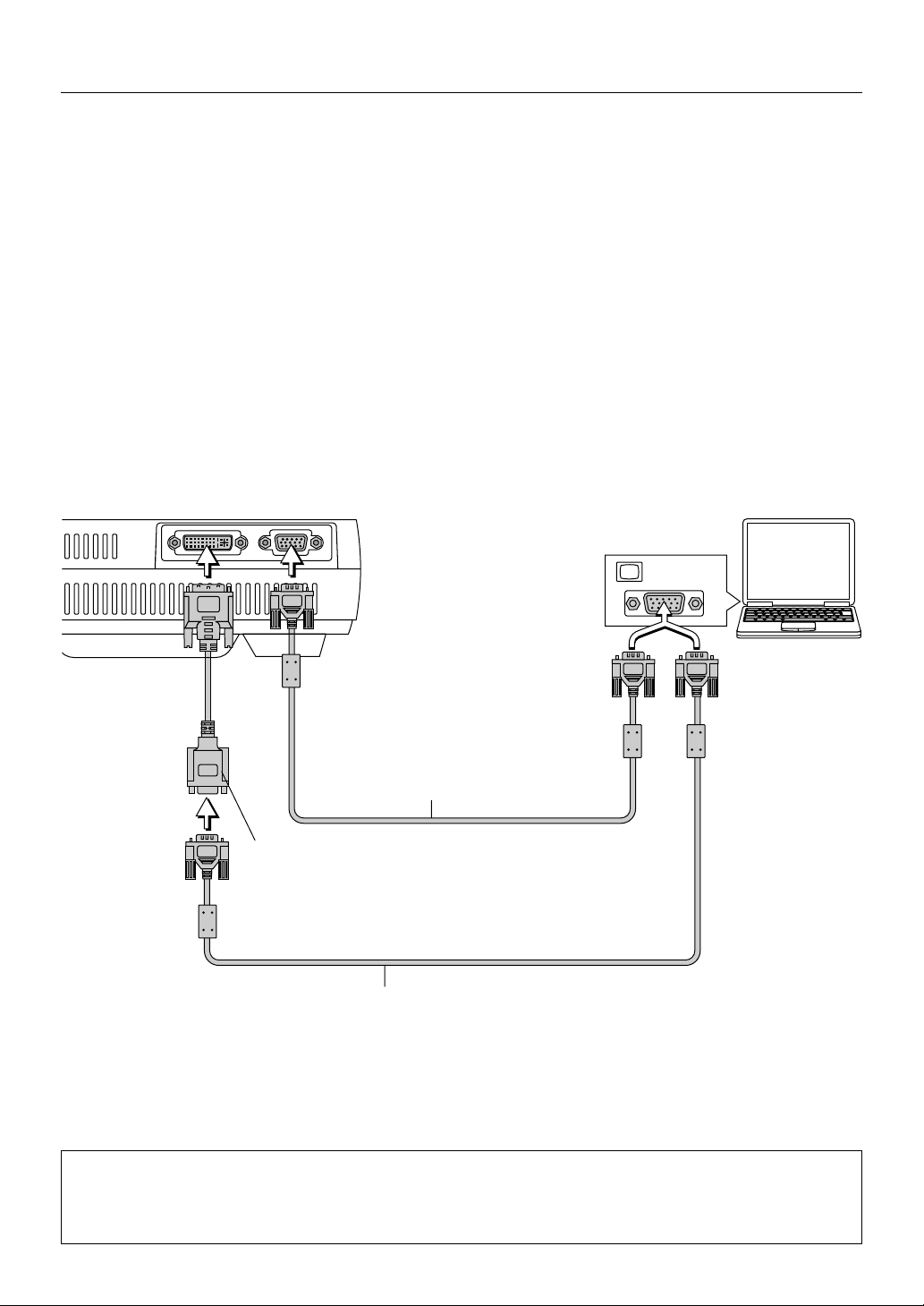
Connections with Personal Computers ..................................................................... E-18
Personal Computers with a DVI Connector ......................................................... E-18
Personal Computers with a Mini D-Sub 15-Pin Connector ................................. E-19
To Output the External Output Signal of a Notebook Computer ......................... E-20
Video Equipment with VIDEO Connectors.......................................................... E-21
Video Equipment with S-VIDEO Connectors ...................................................... E-21
Connections with Component Signals....................................................................... E-22
Connections with the AUDIO Jack ............................................................................ E-23
Power Cable Connections and Switching the Power On/Off ..................................... E-24
Operating................................................................................................................... E-24
Finishing .................................................................................................................... E-26
Adjustment of the Projection Screen........................................................................... E-27
Adjustment of the Projection Screen ......................................................................... E-27
General Operation
General Operation ......................................................................................................... E-29
Input Selection .......................................................................................................... E-29
Automatic Adjustment of Analog RGB ...................................................................... E-29
Viewing the Projector Operation Description............................................................. E-30
Using the Pointer ....................................................................................................... E-30
Enlarging the Image .................................................................................................. E-31
Adjustment of the Volume.......................................................................................... E-31
Correcting Keystone Distortion of the Projection Screen .......................................... E-32
Freezing a Moving Picture......................................................................................... E-32
Cancelling Video and Audio ...................................................................................... E-32
Menu Operations
Menu Operation Method................................................................................................ E-33
Operating Menus ....................................................................................................... E-34
Menu list .................................................................................................................... E-38
Adjustments and Settings
Source Select/Picture/Volume ...................................................................................... E-40
Source Select ............................................................................................................ E-40
Picture ....................................................................................................................... E-40
Volume ...................................................................................................................... E-40
Image Options ................................................................................................................ E-41
Keystone .................................................................................................................... E-41
Lamp Mode ............................................................................................................... E-41
Aspect Ratio .............................................................................................................. E-41
Noise Reduction ........................................................................................................ E-42
Position/Clock............................................................................................................ E-42
Resolution ................................................................................................................. E-43
Video Filter ................................................................................................................ E-43
Factory Default .......................................................................................................... E-44
E-5
Page 6

Table of Contents
Color Management ........................................................................................................ E-45
Gamma Correction .................................................................................................... E-45
Color Matrix ............................................................................................................... E-45
White Balance ........................................................................................................... E-45
Projector Options [Menu].............................................................................................. E-46
Menu Mode ............................................................................................................... E-46
Language .................................................................................................................. E-48
Projector Pointer........................................................................................................ E-48
Menu Display Time .................................................................................................... E-48
Source Display .......................................................................................................... E-49
No Input ..................................................................................................................... E-49
Volume Bar................................................................................................................ E-49
Keystone Bar ............................................................................................................. E-49
Projector Options [Setup] ............................................................................................. E-50
Orientation ................................................................................................................. E-50
Cinema Position ........................................................................................................ E-50
Background ............................................................................................................... E-50
Mouse ....................................................................................................................... E-51
PC Card Viewer Options ........................................................................................... E-52
Capture Option .......................................................................................................... E-52
Signal Select ............................................................................................................. E-53
Auto Adjust (RGB only) ............................................................................................. E-53
Auto Start .................................................................................................................. E-54
Power Management .................................................................................................. E-54
Power Off Confirmation ............................................................................................. E-54
Keystone Save .......................................................................................................... E-55
White Segment .......................................................................................................... E-55
Clear Lamp Hour Meter ............................................................................................. E-55
Communication Speed .............................................................................................. E-56
Default Source Select................................................................................................ E-56
Control Panel Key Lock ............................................................................................. E-56
Tools ............................................................................................................................... E-57
Capture function ........................................................................................................ E-57
PC card file function .................................................................................................. E-58
Chalkboard ................................................................................................................ E-60
Help ................................................................................................................................. E-62
Contents .................................................................................................................... E-62
Information ................................................................................................................ E-63
Using a USB Mouse ....................................................................................................... E-64
Connecting the USB Mouse ...................................................................................... E-64
Operating menus using the USB mouse ................................................................... E-64
Using the PC Card Viewer function .............................................................................. E-65
Miscellaneous
When the STATUS Indicator is Lit/Flashes .................................................................. E-72
Troubleshooting ............................................................................................................. E-73
Cleaning ......................................................................................................................... E-74
Replacing the Lamp Cartridge ..................................................................................... E-75
Specifications ................................................................................................................ E-78
Tab le of Supported Frequency ..................................................................................... E-79
Cabinet Dimensions ...................................................................................................... E-80
E-6
Page 7
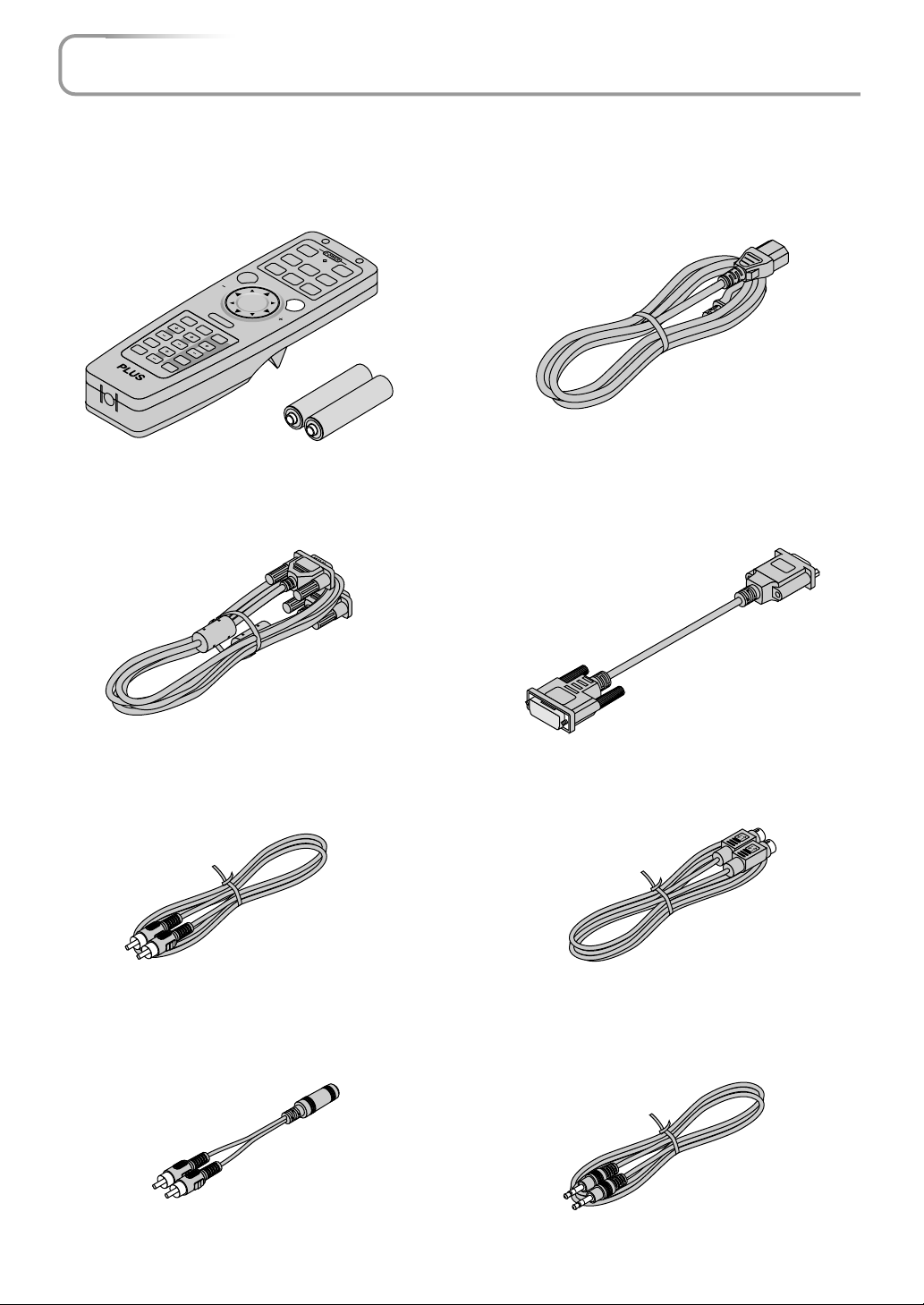
Checking the Supplied Accessories
Remove the main unit and the accessories from the box and check that the following items are included.
Wireless remote control [1] / Size AA batteries [2]
This controls the projector. Please insert the supplied batteries into the remote control prior to first use. (See Page E-13.)
OFF
RGB DVI
VIDEO
(
ON
Digital
S-VIDEO
)
DVI
(
Analog
)
AUTO
PIC MUTE
FREEZE
KEYSTO
VOL.
SLIDE LIST
HELP POINTER
NE
MAGNIFY
FOLDER LIST
MENU PJ
R
-C
L
IC
K
/C
A
N
C
E
L
PC-CARD
SLIDE
RGB signal cable
(Mini D-sub 15-pin, 2 m / 6.6 feet) [1]
This is used in making connections with a personal computer.
See Page E-19 about connections.
No. 772709000
Power cable (1.8 m / 5.9 feet) [1]
This power cable supplies power to the unit. See Page E-24
about connections.
DVI / Mini D-sub 15-pin conversion cable (18 cm / 0.6 feet)
[1]
This is used in making connections with a personal computer.
See Page E-20 about connections.
No. 772708000
Video cable (RCA pin plug, 2 m / 6.6 feet) [1]
This cable is used in the connection of video equipment that
has a video connector. Connections are described on Page E-
21.
No. 771703000
Audio conversion cable (Mini plug / RCA pin plug, 15 cm /
0.5 feet) [1]
This cable is used with equipment whose audio connector is
of the phono pin type. Connections are described on Page E-
23.
No. 770704000
S-Video cable (Mini DIN 4-pin plug, 2 m / 6.6 feet) [1]
This cable is used in the connection of video equipment that
has an S-video connector. Connections are described on Page
E-21.
No. 771709000
Audio cable (Mini plug, 2 m / 6.6 feet) [1]
This cable is used with equipment that has phono type audio
jacks. Connections are described on Page E-23.
No. 769710000
E-7
Page 8
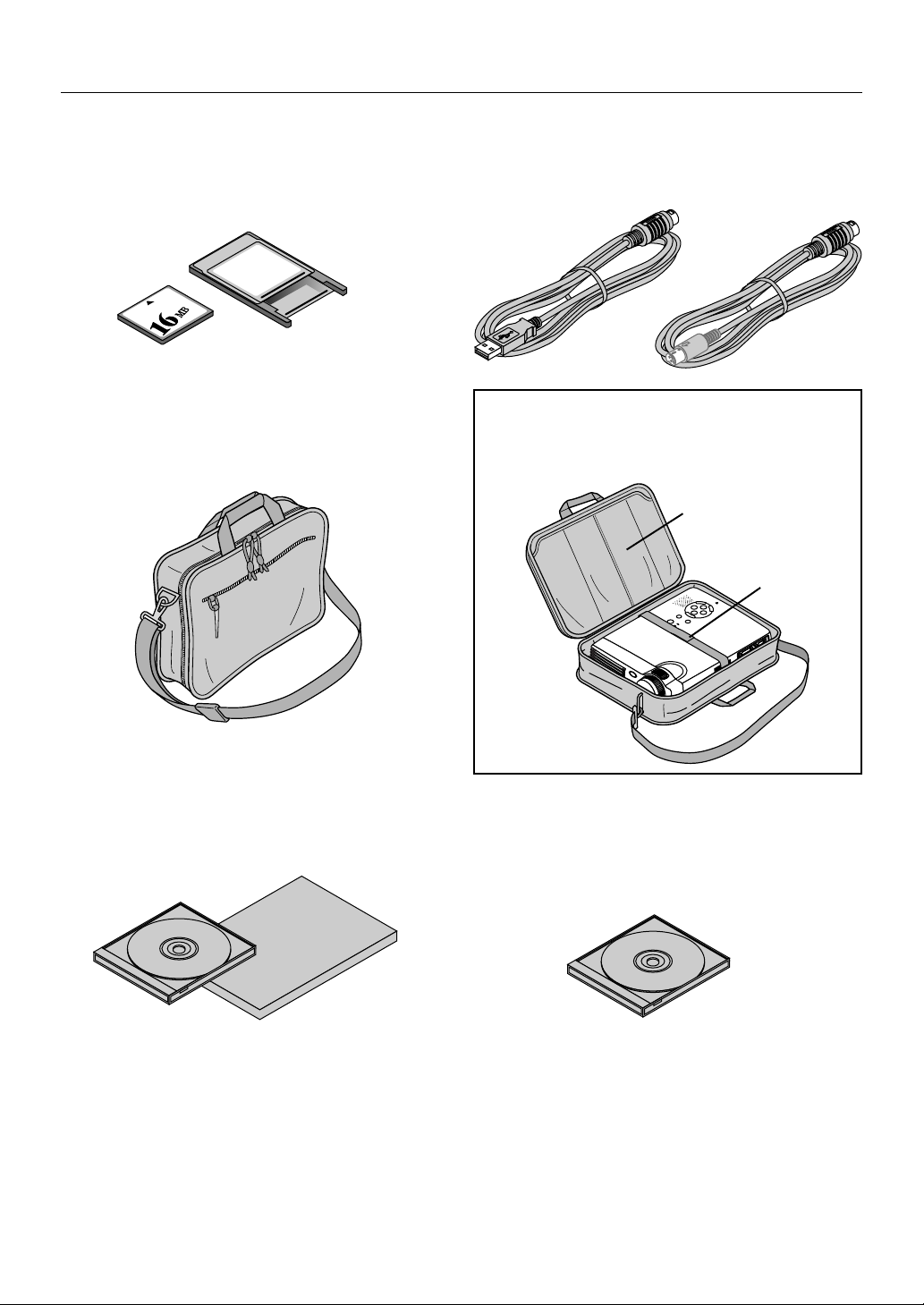
Checking the Supplied Accessories
CompactFlash Card (16 MB) [1] / PC Card Adapter [1]
This card and adapter are used for saving slides created on a
personal computer and for playback on a projector. Usage is
described on Page E-11.
PC Card
Adapter
Carrying case (for projector and accessories) [1]
This is a case designed for storing the projector and its
accessories.
Use this carrying case when storing or moving the projector.
USB mouse cable (2 m / 6.6 feet) [1] No. 769713000 /
PS/2 mouse cable (2 m / 6.6 feet) [1] No. 769712000
This is used when controlling personal computer mouse operation with a remote control. Connections are described on
Page E-14.
HOW TO PUT THE PROJECTOR INTO THE CARRYING CASE
Attach the lens cap to the projector before putting the projector into the carrying case, and then fasten the velcro
strap. Put accessories into the pocket.
Pocket
Velcro strap
User's Manual (CD-ROM edition) [1]
User's Manual (Simplified Edition) [1]
Software CD-ROM (1)
This CD-ROM includes:
PC Card Viewer Utility
PC Card Viewer PPT Converter
PC Control Utility
E-8
Page 9
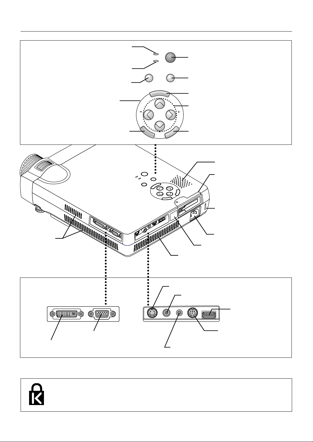
Names of the Main Unit Parts
ACCESS
E
N
T
E
R
PC CARD
CANCEL
Ventilation slots
Front adjuster button [E-28]
(There is also one on the right side.)
-
SELECT
+
M
E
N
A
U
U
T
S
O
T
A
T
U
P
S
O
W
E
S
R
O
UR
C
E
P
O
W
E
R
Remote control sensor [E-13]
Exhaust vents
Zoom ring [E-27]
Focus ring [E-28]
Lens
Lens cap
To protect the lens, attach
the lens cap when the projector is not being used.
Front adjusters [E-28]
Rear adjuster [E-28]
Ventilation slots
Ventilation slots
Lamp cover [E-76]
E-9
Page 10
Names of the Main Unit Parts
POWER indicator [E-24,72]
STATUS indicator [E-24,72]
AUTO button [E-29]
Buttons used in menu
and toolbar operations
ENTER button
POWER
STATUS
ENTER
POWER
AUTO
POWER
STATUS
AUTO
SOURCE
MENU
MENU
SELECT
-
POWER
SOURCE
SELECT
ENTER
CANCEL
+
POWER button [E-24]
SOURCE button [E-29]
MENU button
SELECT ▲▼ buttons
CANCEL button
Speaker
Used with CompactFlash Cards
[E-11]
CANCEL
PC CARD
ACCESS
D
R
A
C
C
P
Built-in security slot
(See description below.)
Ventilation slots
DVI connector [E-18]
D
V
I
R
G
B
USB MOUSE
MOUSE
AUDIOVIDEOS-VIDEO
AC IN connector [E-24]
Remote control sensor [E-13]
Ventilation slots
S-VIDEO connector [E-21]
VIDEO connector [E-21]
RGBDVI
RGB connector [E-19,22]
USB MOUSEMOUSEAUDIOVIDEOS-VIDEO
MOUSE connector [E-14]
AUDIO connector [E-23]
Built-in Security Slot
This security slot supports the MicroSaver Security System manufactured by
Kensington Microware Inc.
USB MOUSE connector
[E-64]
E-10
Page 11
N
D
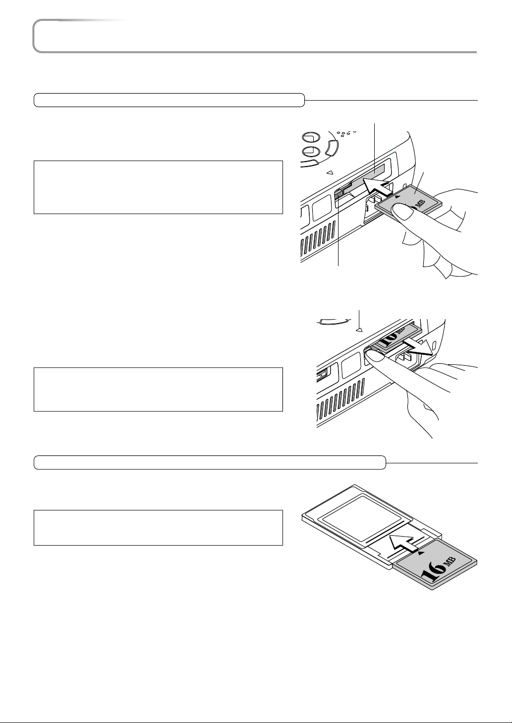
Using CompactFlash Cards
CompactFlash Cards are used in the data storage of presentation materials created by personal computer as well as in
the storage and playback of images that are projected by the projector (i.e., image capture).
Insertion to and Removal from PC Card Slots
Insertion
Keeping the card level and with the front side facing upward, slowly insert the card into the PC Card slot.
When fully inserted the PC Card eject button pops out.
Note: Insertion Orientation of CompactFlash Card
The card has a specific insertion orientation. The card cannot be inserted
backward even if attempted and excessive force will cause damage to the
equipment. If available, please see the instruction manual of your CompactFlash
Card for information about insertion direction.
T
TER
SE
PC Card Slot
CANCEL
PC CARD
ACCESS
PC CARD
PC Card eject button
PC CARD ACCESS indicator
CompactFlash
Card
ENTER
PC CAR
ACCESS
Removal
A press of the PC Card eject button will cause the card to pop out a little.
Hold the card by both edges and remove it.
Note:
Do not eject the card when the PC CARD ACCESS indicator is lit (i.e., when the
card is being accessed for data). Doing so will damage the CompactFlash
Card.
SB MOUSE
PC CARD
When Inserting to the PC Card Slot of a Personal Computer
Hold the CompactFlash Card in the proper orientation as illustrated in
the diagram and firmly insert it into the accessory PC Card adapter. Now
insert the adapter into the PC Card slot of the personal computer
Note:
Memory cards that can be used in this projector are CompactFlash Cards of
the CFA specification.
PCCard
Adapter
E-11
Page 12
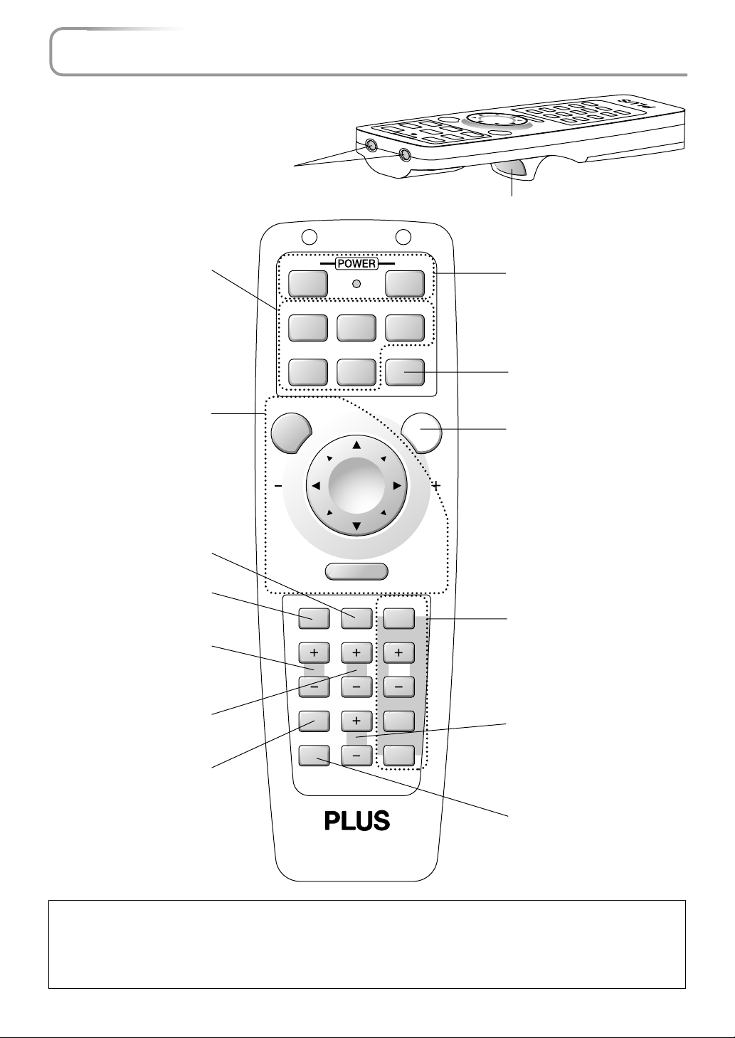
Names of the Remote Control Parts
Infrared transmitter [E-13]
Used in menu and mouse operations [E15,33]
Buttons used for input selection [E-29]
RGB button, DVI (Digital) button,
DVI (Analog) button, VIDEO button, S-VIDEO button
Buttons used in menu and
mouse operations [E-15,33]
POINTER button [E-30]
(Displays the pointer.)
HELP button [E-30]
(Displays Help.)
KEYSTONE button [E-32]
(Adjusts keystone distortion of
the projected picture.)
ONOFF
(
)
RGB DVI
VIDEO
MENU PJ
HELP POINTER PC-CARD
KEYSTONE
Digital
S-VIDEO AUTO
R-CLICK /CANCEL
MAGNIFY
DVI
SLIDE
(
Analog
POWER button [E-24]
ON button: Switches on the power
)
OFF button: Switches off the power
AUTO button [E-29]
(Adjusts the analog RGB image
automatically.)
PJ button [E-15]
(Changes the button used for
mouse operation to the button used
for projector operation.)
Viewer function control button
[E-68]
(Used in viewer switching and selection of slides.)
MAGNIFY button [E-31]
(Enlarges and reduces the
screen (back to original size).)
FREEZE
PIC MUTE
VOL.
FOLDER LIST
SLIDE LIST
VOL. button [E-31]
(Adjusts the volume.)
FREEZE button [E-32]
(Freezes moving pictures)
PIC MUTE button [E-32]
(Temporarily cancels the video and
audio)
Note: Handling of the Remote Control
* Do not drop the remote control or handle it inappropriately.
* Do not expose the remote control to water or other liquids. Should the remote control become wet, wipe it dry immediately.
* Try to avoid use in hot and/or humid locations.
* Remove the batteries from the remote control when it is not going to be used for a long period.
* Some operations are available only through the use of the remote control and attention should be given to its careful handling.
E-12
Page 13
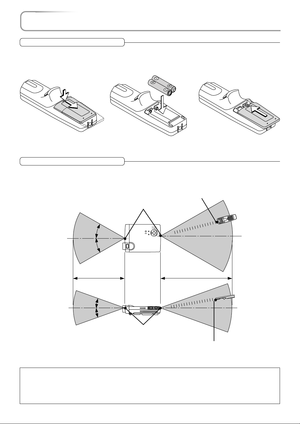
Preparing the Remote Control
Inserting Batteries
1
Slide the battery compartment
cover (located on the bottom
of the remote control) and pull
off.
* When replacing the batteries, replace both batteries at the same time with the same type of size AA battery.
2
Insert the batteries to match the
"+" and "-" as indicated inside
the compartment.
3
Return the cover to the original
condition.
Remote Control Range
Point the infrared transmitter of the remote control toward the remote control sensor located at the front or rear of the main unit
and operate.
Reception of the remote control signal should generally be possible within the range illustrated below.
Remote control infrared transmitter
Remote control sensor
Remote control
30˚
30˚
5 m / 16.4 feet
20˚
20˚
Remote control sensor
Note:
* Exposure of the main unit's remote control sensor or the remote control infrared transmitter to bright light or the obstruction of the signal
by an obstacle located in the pathway may prevent operation.
* The remote control will not function when the battery is exhausted.
* When the same button of the remote control is held down for one minute or longer, the energy saving function will be activated and the
remote control transmission will stop. This is not a fault of the unit.
7 m / 23.0 feet
Remote control
Remote control infrared transmitter
E-13
Page 14
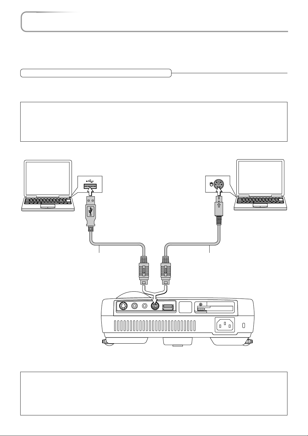
Operating a Personal Computer with the Remote Control
When the personal computer and projector are connected, a portion of the buttons of remote control assume the mouse
functions of the personal computer.
Aim the remote control in the direction of the projector's remote control sensor and operate it to control the personal
computer mouse operations.
Connections with the Personal Computer
Disconnect the mouse that is currently used with the personal computer and connect the appropriate cable to that
connector. The cable will differ depending on the port form of the personal computer's connector. Please see the instruction manual of the personal computer for information about the personal computer's connector for mouse connections.
Note
* Make sure that the power of the personal computer has been switched off before making connections.
* Connect cables securely.
* Depending on such factors as the type of connection and the operating system of the personal computer, a change of settings or restarting
of the computer may be necessary.
* Connection and use of a USB mouse cable to the USB MOUSE connector of this projector is not possible.
To USB connector of computer
supporting IBM PC/AT Compatible
or a Macintosh
USB mouse cable (Supplied item) PS/2 mouse cable (Supplied item)
To MOUSE connector
AUDIOVIDEOS-VIDEO
USB MOUSEMOUSE
To mouse (PS/2) connector of computer supporting
IBM PC/AT Compatible
PC CARD
Note: Connections with USB Cables
* Computers supporting IBM PC/AT Compatible require Windows 98/2000 operating system.
* When the cable is disconnected and then reconnected to the USB port of the personal computer or the MOUSE connector of the projector,
allow at least 5 seconds before reconnecting. Do not repeatedly disconnect and reconnect the cable in a momentary fashion. The personal
computer may not be able to correctly identify the projector as a result.
* The supplied USB cable is a dedicated cable for this projector. There is no guaranty that it will work in connections with other USB
equipment.
E-14
Page 15
Operating a Personal Computer with the Remote Control
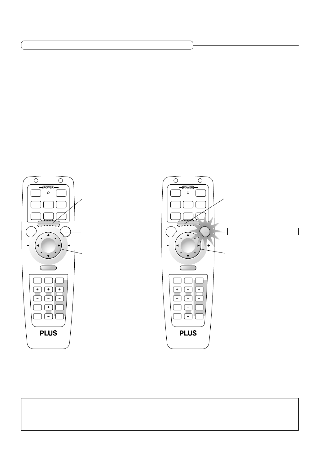
Switching Between Projector Mode and Personal Computer Mode
The SELECT, CANCEL, and ENTER buttons of the remote control assume the role of the mouse function buttons of the personal
computer.
Switching between the projector and personal computer modes selects whether the aforementioned 3 buttons are set as the
operation buttons of the projector or the mouse function buttons of the personal computer.
Projector Mode
Press the PJ button to light it in red and the buttons will be set to the functions of the SELECT, CANCEL, and ENTER buttons.
Personal Computer Mode
When the PJ button is unlit or has been pressed again and is no longer illuminated, the buttons return to the functions of the
mouse function buttons.
Buttons other than the mouse function buttons serve as the operation buttons of the projector regardless of the projector and
personal computer modes.
ONOFF
(
)
RGB DVI
VIDEO
MENU PJ
R-CLICK /CANCEL
HELP POINTER PC-CARD
KEYSTONE
FREEZE
PIC MUTE
(
Digital
DVI
Analog
S-VIDEO AUTO
SLIDE
MAGNIFY
VOL.
FOLDER LIST
SLIDE LIST
)
Function of the personal
computer left button
(Located on the bottom of
the remote control.)
When the PJ button is not lit
Mouse function
R-CLICK (Right button)
function
(
RGB DVI
VIDEO
S-VIDEO AUTO
MENU
R-CLICK /CANCEL
HELP POINTER PC-CARD
KEYSTONE
MAGNIFY
FREEZE
VOL.
PIC MUTE
Digital
ONOFF
)
(
DVI
Analog
SLIDE
FOLDER LIST
SLIDE LIST
)
Function of the projector
ENTER button
(Located on the bottom of
the remote control.)
PJ
When the PJ button is lit
SELECT button function
CANCEL button function
Note:
* When the PJ button has been pressed and a button operation is not executed within 10 seconds, the lamp will go out and the projector will
return to the personal computer mode.
* When the MENU button, POINTER button, HELP button, PC-CARD button, FOLDER LIST button, or SLIDE LIST button is pressed, the PJ
button lights automatically and the projector mode is set.
E-15
Page 16

The Procedure Up to Projecting to the Screen
Perform setup adjustments in the following order.
1 Position the projector
Determine the locations to set up the screen and the projector.
See "Screen Size and Projection Distance" on Page E-17
2 Connect the video equipment and personal computer
Connect your equipment to the projector.
When making connections with the personal computer's DVI connector or RGB connector, see
"Connections with Personal Computers" on Pages E-18 and E-19.
When making connections with the video equipment's video connector or an S-video connector,
see "Connections with Composite Signals" on Page E-21.
When making connections with the video equipment's YCbCr connector or YPbPr connector,
see "Connections with Component Signals" on Page E-22.
When playing the audio through the built-in speaker of the projector, see "Connections with the
AUDIO Jack" on Page E-23.
3 Connecting the power cable and switching on the power
See "Operating" on Page E-24.
See "Finishing" on Page E-26.
4 When selecting the language of menu displays, etc.
(Only when the power is first switched on following purchase)
See "When the Start Screen Appears Upon Switching On the Power" on Page E-25.
5 Switching on the power of the personal computer and video equipment
6 Properly adjust the projection image to the screen
See "Adjustment of the Projection Screen" on Page E-27.
7 Selecting input equipment
See "Input Selection" on Page E-29.
8 Adjust the screen or video image
Adjust the image to the optimum condition as required.
See the Table of Contents for the adjustment items.
Note:
* Please purchase a screen.
*A component cable (Order code 28-690), which is available separately, is required to connect a DVD player or other equipment with YCbCr
connectors.
*A component cable (Order code 28-690), which is available separately, is required to connect high definition (HD) video equipment or other
equipment with YPbPr connectors.
E-16
Page 17
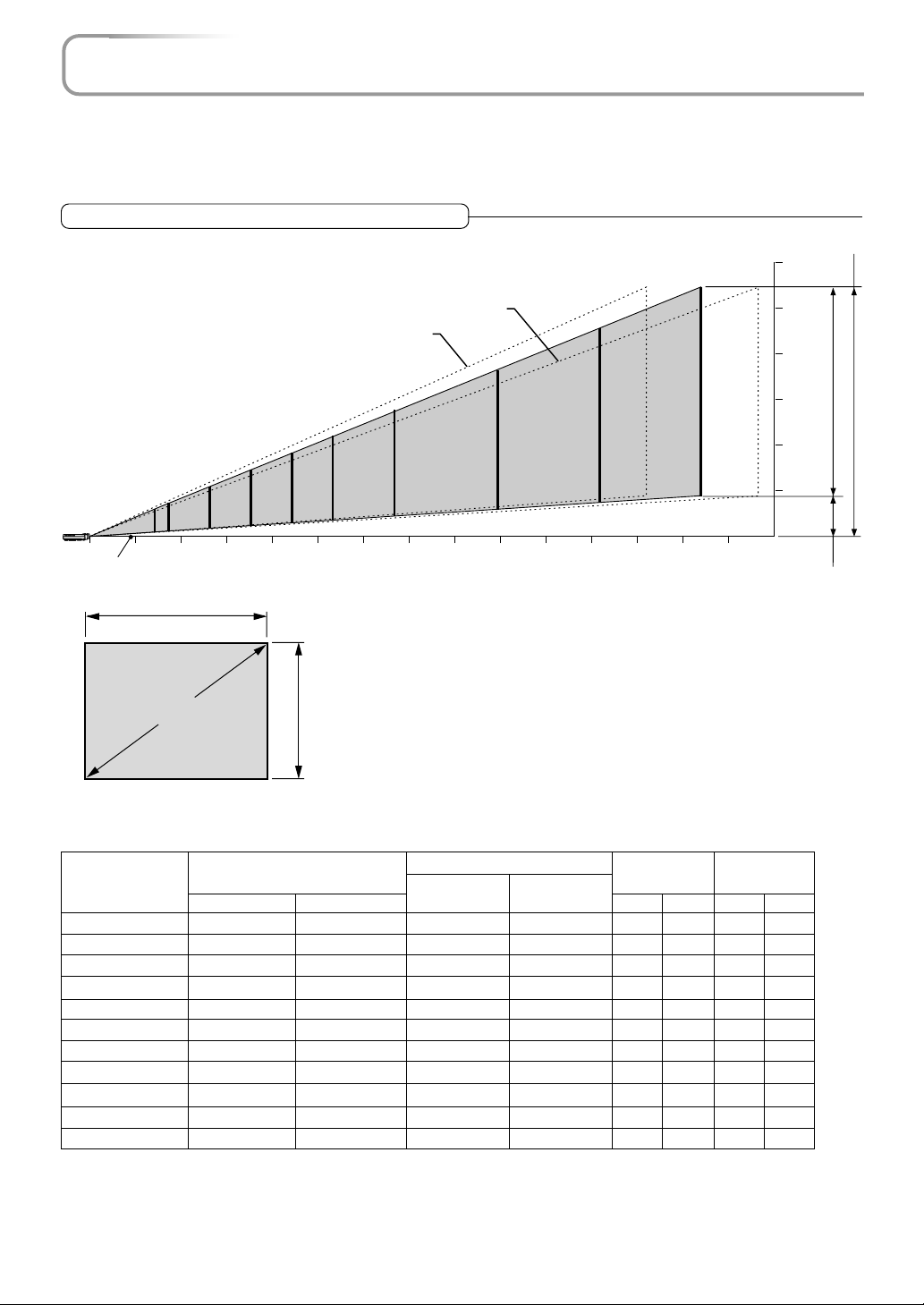
Placement Guide
* Use this information as a guide to find out about the screen size when the projector is placed at a certain location, or
to find out the approximate size of a screen that will be required.
* The projection distance over which focussing is adjustable is 1.3 m (4.2 feet) to 14.65 m (48 feet) from the front of the
projector lens. The projector should be placed within this range.
Screen Size and Projection Distance
Tele
Wide
Height from center of lens to top edge of the projection
250"
200"
150"
120"
100"
80"
60"
27-33"
01
Center of
lens
Screen size (Diagonal)
40"
(3.28)2(6.56)3(9.84)4(13.12)5(16.40)6(19.68)7(22.96)8(26.24)9(29.52)10(32.80)11(36.08)12(39.37)13(42.65)14(45.93)15(49.21)
Width
Height
Projection Distance
m (feet)
300"
Height from center of lens to
bottom edge of the projection
6 (19.68)
5 (16.40)
4 (13.12)
3 (9.84)
2 (6.56)
1 (3.28)
h2
0
(m)
(feet)
h1
Screen Height
Screen Size
Designation
(Inches)
27"
33"
40"
60"
80"
100"
120"
150"
200"
250"
300"
Screen Size
Width x Height
(m) (feet)
0.560.42
0.670.50
0.810.61
1.210.91
1.621.21
2.031.52
2.431.82
3.042.28
4.063.04
5.083.81
6.094.57
1.831.37
2.191.64
2.652.00
3.962.98
5.313.96
6.664.98
7.975.97
9.977.48
13.329.97
16.6612.50
19.9814.99
Projection Distance
(m) (feet)
Wide - Tele Wide - Tele
– - 1.30
1.30 - 1.57
1.58 - 1.91
2.40 - 2.89
3.21 - 3.87
4.03 - 4.85
4.85 - 5.83
6.07 - 7.30
8.12 - 9.75
10.16 - 12.20
12.20 - 14.65
– - 4.26
4.26 - 5.15
5.18 - 6.26
7.87 - 9.48
10.53 - 12.69
13.22 - 15.91
15.91 - 19.12
19.91 - 23.95
26.64 - 31.98
33.33 - 40.02
40.02 - 48.06
E-17
Height h1 Height h2
(m) (feet) (m) (feet)
0.50
0.59
0.72
1.09
1.45
1.81
2.18
2.73
3.64
4.55
5.46
1.64
1.93
2.36
3.57
4.75
5.93
7.15
8.95
11.94
14.92
17.91
0.08
0.09
0.11
0.17
0.23
0.29
0.35
0.44
0.59
0.74
0.89
0.26
0.29
0.36
0.55
0.75
0.95
1.14
1.44
1.93
2.42
2.91
Page 18
Connecting Personal Computers and Video Equipment
Connecting this unit with a personal computer permits presentation data to be projected as a large screen display at
conferences, lectures, and on other occasions. Furthermore, connecting this unit to a DVD player or other video equipment source in combination with an audio/video amplifier and speaker system will allow you to enjoy convincing home
theater.
Connections with Personal Computers
Please check the following matters before making connections to the personal computer.
* Suitable resolution for the projector is 1024768 dots (XGA), and the displayable resolution will differ depending on the
personal computer.
See "Table of Supported Frequency" on Page E-79.
* When making connections to a Macintosh, change to a displayable resolution at the personal computer side.
* The setting method of the personal computer will differ depending on the personal computer that you are using. For informa-
tion, read the instruction manual for your personal computer, read the on-line help, or contact the manufacturer of your per-
sonal computer.
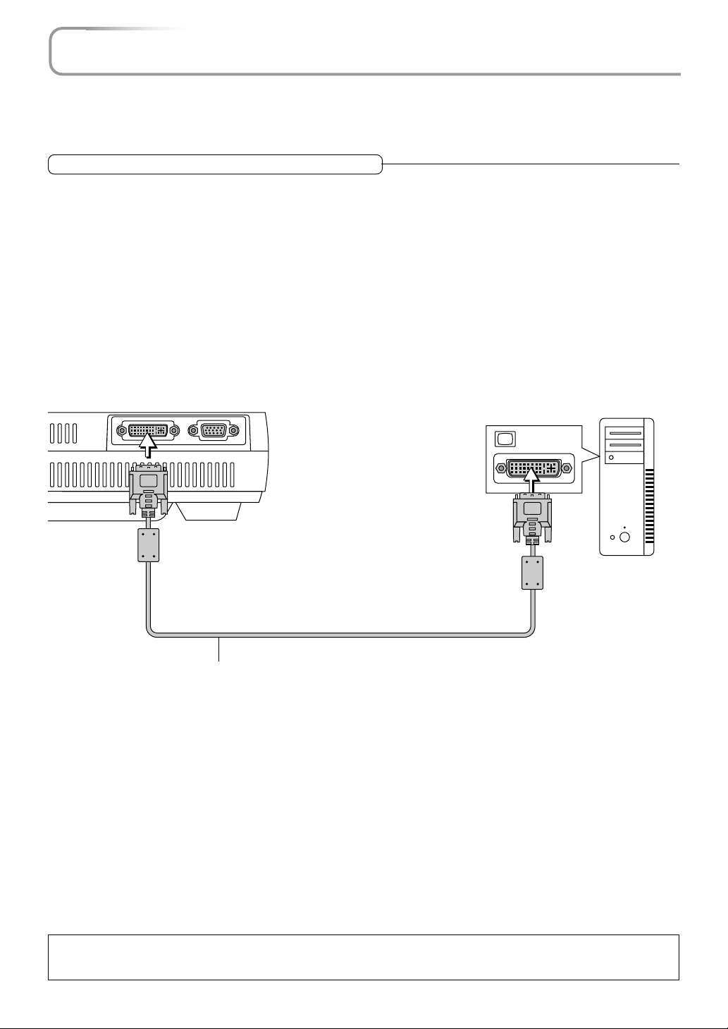
Personal Computers with a DVI Connector
* Make the connection to the DVI connector of the projector using a DVI-D cable (which is commercially available).
When connecting, arrange the connectors in the proper orientation and plug in. Turn the screw knobs and fasten to the
connector of the projector.
* Switch the input selection of the projector to "DVI (DIGITAL)".
RGBDVI
DVI-D cable
(Available as an option. Order code: 28-697)
Monitor output
Personal computer
Note:
This projector uses a 29-pin DVI-I connector that supports the digital interface. Digital signal TMDS (Transition Minimized Differential Signalling) of the DVI (Digital Visual Interface) standard is used.
E-18
Page 19
Connecting Personal Computers and Video Equipment
Personal Computers with a Mini D-Sub 15-Pin Connector
* When making connection with the RGB connector of the projector, use the supplied RGB signal cable.
When connecting, arrange the connectors in the proper orientation and plug in. Turn the screw knobs and fasten to the
connector of the projector.
Switch the input selection of the projector to "RGB".
* When making connection with the projector's DVI connector, make the connection via the supplied DVI/mini D-Sub 15-pin
conversion cable.
Switch the input selection of the projector to "DVI (ANALOG)".
RGBDVI
RGB signal cable (Supplied item)
DVI/mini D-Sub 15-pin conversion cable
(Supplied item)
RGB signal cable (Supplied item)
Monitor output
Personal computer
Note:
* Before making connections, check the power of the projector and the equipment to be connected is switched off.
* When projection will be with a notebook computer connected, knowledge will be required for the cable connection and notebook computer
startup procedure as well as the operation that follows startup. Please consult the instruction manual of your notebook computer or the online help.
E-19
Page 20

Connecting Personal Computers and Video Equipment
To Output the External Output Signal of a Notebook Computer
When projection will be with a notebook computer connected, knowledge will be required for the cable connection and notebook
computer startup procedure as well as the operation that follows notebook startup. Please consult the instruction manual of your
notebook computer or the on-line help while performing the following procedure.
Check whether a signal is being sent from the notebook computer to the projector.
1
An indication appearing on the liquid crystal display of the notebook computer does not necessarily mean that an external
output signal is being output.
REFERENCE: When the sync frequencies under [Help] → [Information] on the menu of the projector do not display, an
external output signal is not being output from the personal computer.
Should a sign not be output from the notebook computer, please try the operation described below.
2
For an IBM PC/AT compatible computer, press the [Fn] key plus any one of the [F1] to [F12] keys. (See the table below.)
Manufacturer Model Key
akia All computers Fn + F2
COMPAQ ARMADA Series Fn + F4
PRESARIO Series Fn + F3
DELL All computers Fn + F8
FUJITSU All computers Fn + F10
GATEWAY All computers Fn + F3
IBM All computers Fn + F7
NEC All computers Fn + F3
Panasonic All computers Fn + F3
SHARP All computers Fn + F5
SONY All computers Fn + F7
SOTEC All computers Fn + F3
TOSHIBA All computers Fn + F5
Note: Table information is current to June 2001.
Note:
When the liquid crystal display of the notebook computer and the projector are displayed at the same time, the projected image might not be
correct even though the liquid crystal display shows a correct indication. Should this occur, stop the simultaneous display of the notebook
computer and try the mode with external output only. Try an operation such as that described in aforementioned Step 2 and try closing the
liquid crystal panel which might result in external output only.
E-20
Page 21
Connecting Personal Computers and Video Equipment
Connections with Composite Signals
Video Equipment with VIDEO Connectors
* Make the connection to the VIDEO connector of the projector using the supplied video cable.
* Switch the input selection of the projector to "VIDEO".
Video Equipment with S-VIDEO Connectors
* Make the connection to the S-VIDEO connector of the projector using the supplied S-video cable.
* Switch the input selection of the projector to "S-VIDEO".
Video deck, DVD player, document
camera, etc.
AUDIOVIDEOS-VIDEO
USB MOUSEMOUSE
PC CARD
VIDEO
S-VIDEO
Video cable (Supplied item)
S-Video cable (Suppled item)
E-21
Page 22
Connecting Personal Computers and Video Equipment
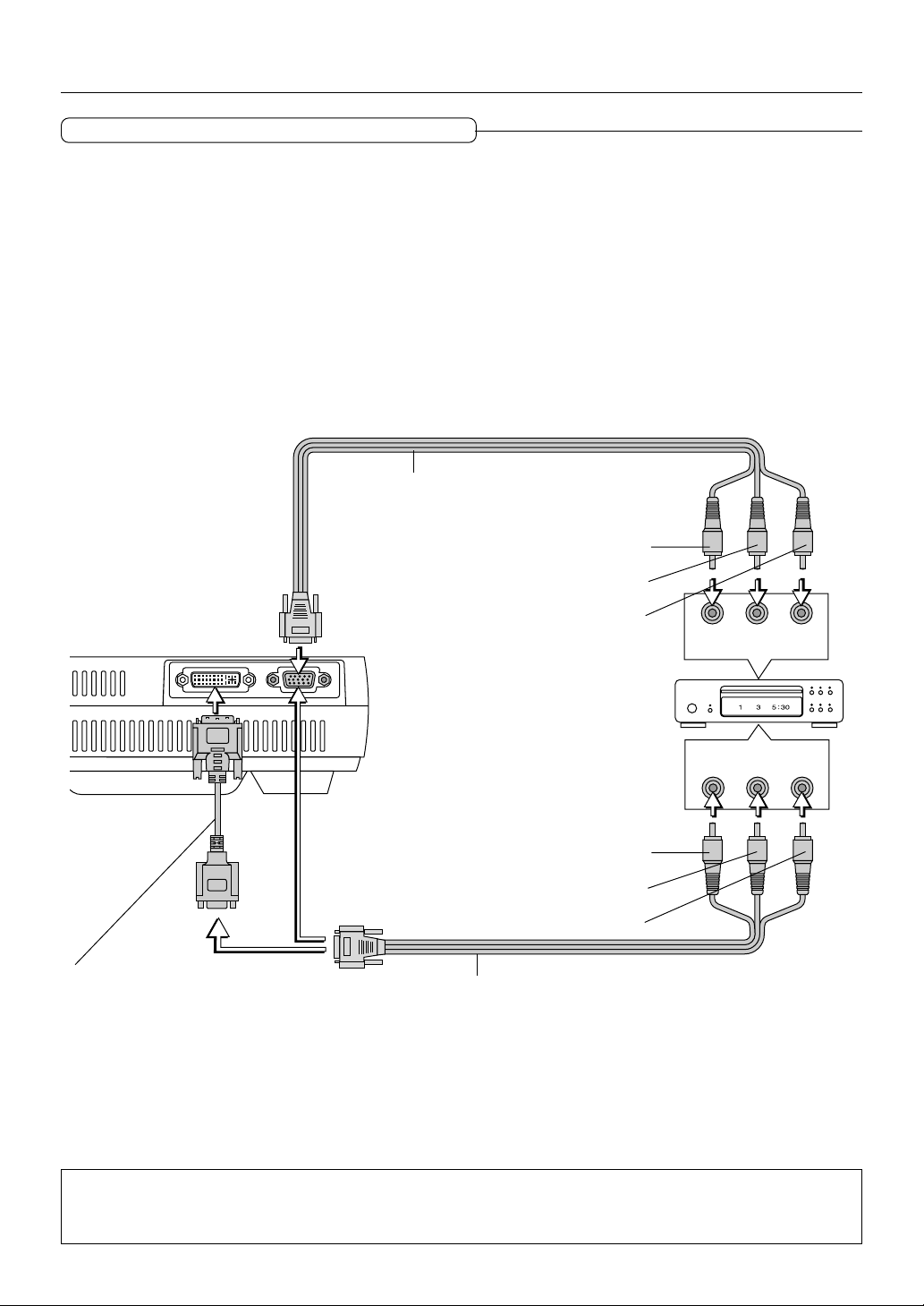
Connections with Component Signals
When the Video Connectors are Y, Cb, and Cr Connectors
* Make the connection to the projector's RGB connector using the supplied component cable.
* Switch the input selection of the projector to "RGB".
Usually, the projector identifies RGB and component automatically, but when identification cannot be made, set the RGB signal
to component from the projector's menu with the [Setup] → [Page 3] → [Signal Select] screens.
When the Video Connectors are Y, Pb, and Pr Connectors
* Make the connection to the projector's RGB connector using the supplied component cable.
* Switch the input selection of the projector to "RGB".
When making connection to a YPbPr output connector (i.e., a high definition video output) such as high definition video, use the
[Color Management] → [Color Matrix] screen of the menu to set [Select Color Matrix] to HDTV, and set [Select Color Matrix
Type] to Pb/Pr.
Component cable (Available as an option)
Order code: 28-690
Green
Blue
DVI / Mini D-sub 15-pin conversion
cable (Supplied item)
Red
CrCbY
COMPONENT
RGBDVI
COMPONENT
PrPbY
Green
Blue
Red
Component cable (Available as an option)
Order code: 28-690
Note:
When connecting a component signal to the DVI connector, connect a component cable via the supplied DVI/mini D-Sub 15-pin conversion
cable. The input selection at this time will be "DVI (ANALOG)", and the signal selection and color matrix settings will be the same as with
analog RGB.
E-22
Page 23
Connecting Personal Computers and Video Equipment
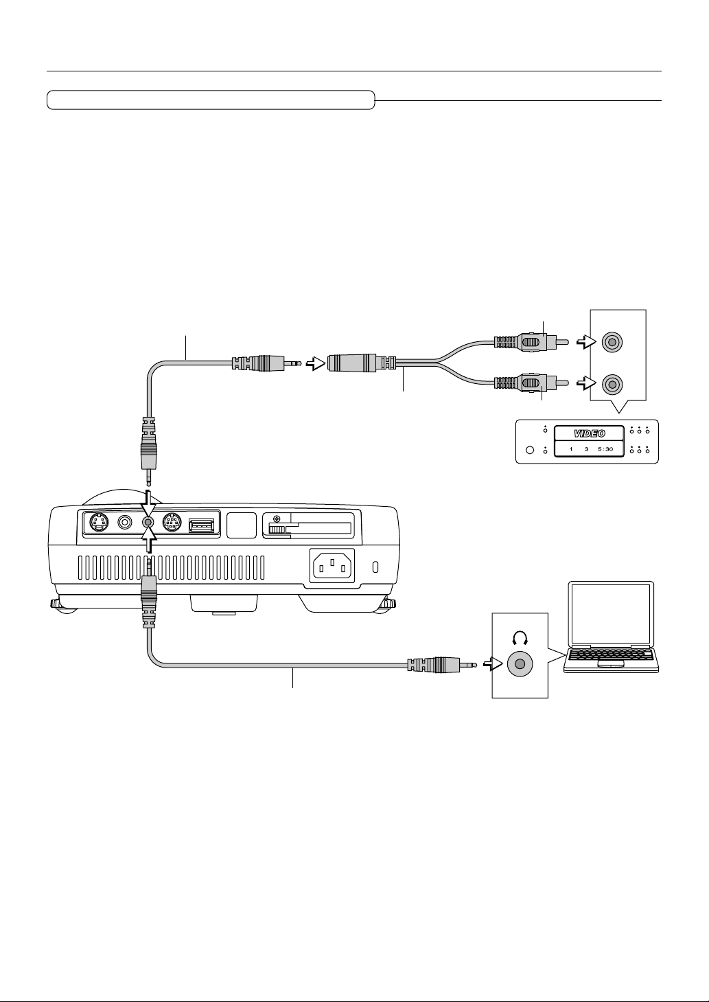
Connections with the AUDIO Jack
* Make the connection to the projector's AUDIO jack using the supplied audio cable. When the audio jack of the equipment that
is to be connected is of the RCA phono type, make connection via the supplied audio conversion cable.
* The built-in speaker of the projector provides monaural audio. To enjoy convincing audio reproduction, please connect the
audio output of the video equipment to your audio system.
* The built-in speaker outputs the audio of the equipment connected to the AUDIO jack.
Audio cable (Supplied item)
AUDIOVIDEOS-VIDEO
USB MOUSEMOUSE
Audio conversion cable
(Supplied item)
PC CARD
Audio cable (Supplied item)
White
Red
AUDIO
E-23
Page 24
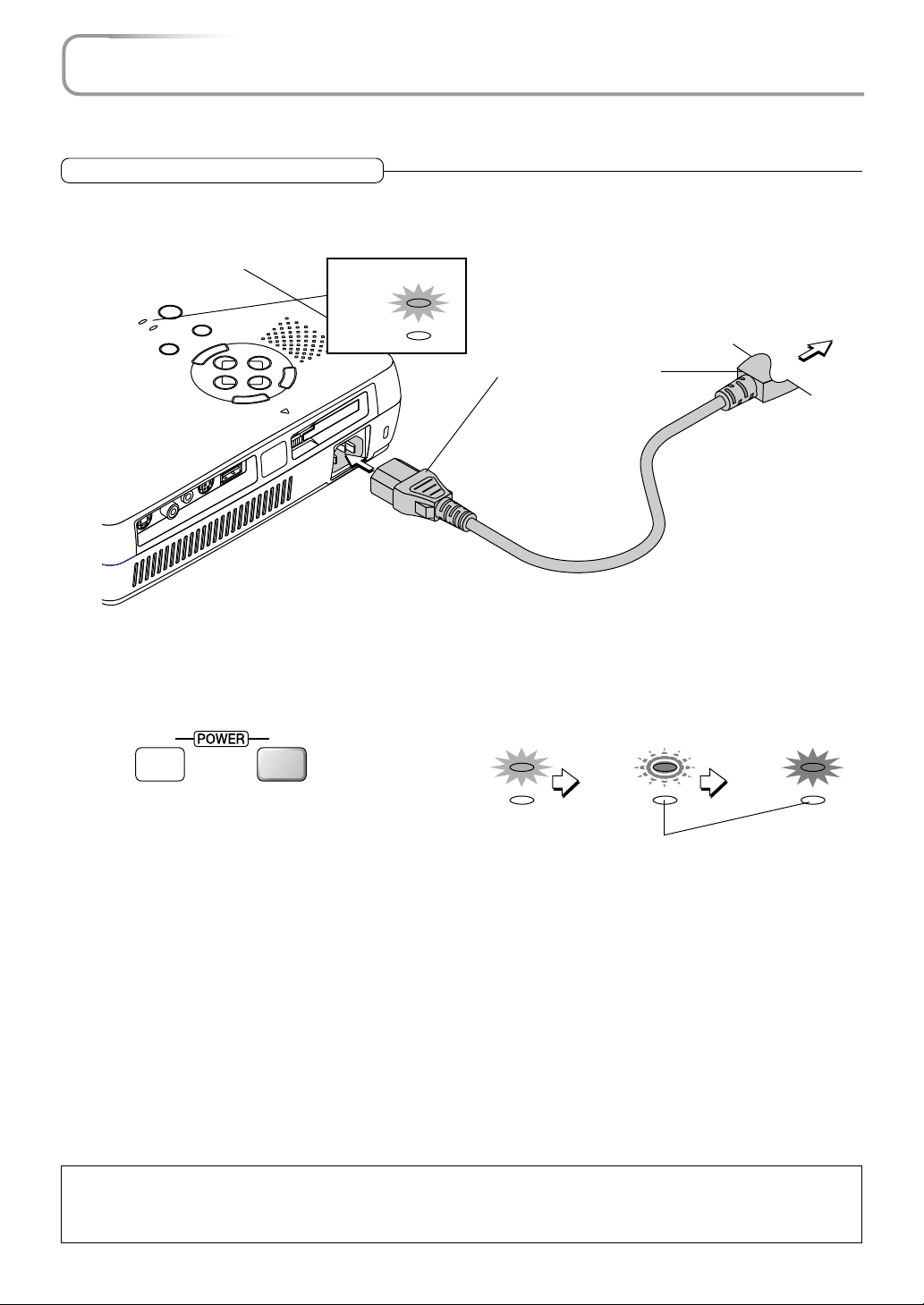
Power Cable Connections and Switching the Power On/Off
There is an order in which the power cable is connected and the power is switched on/off.
Operating
Connect the AC IN connector of the projector and the power outlet using the supplied power cable.
1
The POWER indicator will light in amber, and the unit will enter the standby mode.
Lit amber
CANCEL
ACCESS
PC CAR
D
POWER
STATUS
POWER
POWER
STATUS
Switch on the projector power
2
SOURCE
AUTO
MENU
SELECT
-
N
E
USB MOUSE
MOUSE
AUDIOVIDEOS-VIDEO
+
R
E
PC CARD
T
Projector operation: Press the POWER button.
Remote control operation: Press the POWER ON button.
ONOFF
Firmly plug in all the way.
Lit amber
POWER
STATUS
Flashes green
(Approximately
60 seconds)
POWER
STATUS
To wall outlet
Lit green
Power is on
POWER
STATUS
This indicator is also lit green in Eco-mode.
* The language selection screen will appear when the power is switched on for the first time following purchase. See Page
E-25 for information about language selection.
* The POWER indicator changes to a flashing green and lights steadily after about 60 seconds. The projection screen
reaches normal mode brightness.
* When [Auto Start] has been set to ON, the projector starts automatically upon connecting the power cable.
* The POWER indicator's steady green light and the STATUS indicator's flashing amber indicate that the projector is retrying
to turn on the lamp.
* At such times that the power does not come on, see "When the STATUS Indicator is Lit/Flashes" on Page E-72.
The projector is now capable of regular projection.
Switch on the power of the connected equipment
3
Note:
* When the power plug will be unplugged from the power outlet, please place the projector near the power outlet so that it may be reached
easily.
* Press the POWER button or the POWER ON button after the POWER indicator is lit in amber.
E-24
Page 25
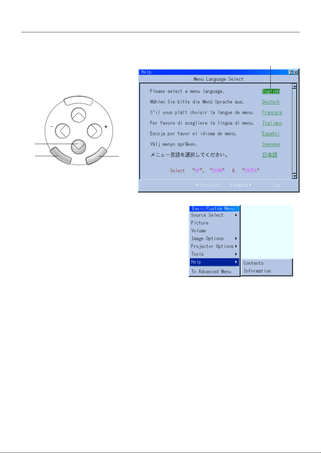
Power Cable Connections and Switching the Power On/Off
When the Start Screen Appears Upon Switching On the Power
The start screen will appear when the power is switched on for the first time following purchase. Follow the procedure
below to select the display language of the projector.
MENU
SELECT
(1)
Cursor
(2)
ENTER
CANCEL
(3)
(1) Press the SELECT ▼ button of the projector and align the green
cursor with [English].
When remote control operation is used, set the unit to projector mode
(in which the PJ button lights in red) before performing this procedure.
(2) Press the ENTER to finalize.
The menu will be displayed in the selected language.
(3) Press the CANCEL button to delete the menu.
This completes the selection of the display language.
E-25
Page 26

Power Cable Connections and Switching the Power On/Off
Finishing
1
Switch off the power of the connected equipment
Switch off the power of the projector
2
Projector operation: Press and hold the POWER button for 2 seconds or longer.
Remote control operation: Press and hold the POWER OFF button for 2 seconds or longer.
Lit green
ONOFF
When a check has been placed in the [Power Off Confirmation] box (as described on
Page E-54), the message screen will be displayed. When performing operations with
the remote control, press the PJ button (which will light in red), then press the SELECT button, select [Yes], and press the ENTER button.
A message to the effect of "Wait a little while" is displayed, the power is switched off
a little while later, the POWER indicator flashes green for 90 seconds and then turns
to amber with a steady light (indicating the standby condition).
Unplug the power cable
3
Check that the POWER indicator is lit in amber and then unplug the power cable.
The POWER indicator will go off when the power cable is unplugged.
POWER
STATUS
This indicator is also lit green in Eco-mode.
Flashes green
(Approximately
90 seconds)
POWER
STATUS
Lit amber
Standby condition
POWER
STATUS
CAUTION
Do not unplug the power cable when the POWER indicator is flashing green. Doing so may shorten the life of the lamp or
result in breakdown of the projector.
E-26
Page 27

Adjustment of the Projection Screen
Switch on the power of the connected equipment and make the adjustments with the video signal being input to the
projector.
Adjustment of the Projection Screen
Turn the zoom ring and adjust the size of the screen.
1
Adjust to the size to fill the screen. If the size of the screen is outside of the adjustment range, move the projector back or
forward.
Zoom ring
Smaller screen
Larger screen
Adjust the projection image to the screen.
2
Check that the screen is set level and vertically.
(1) If the image is shifted to the left or right, move the main unit horizontally. (Align the center of the screen and the center of
the projector lens.)
(2) If the image is shifted vertically, move the image up or down with the adjuster. See "Making Adjustments with the Adjust-
ers" on Page E-28.
(3) If the image is slanted, adjust by turning the right or left front adjuster. See "Making Adjustments with the Adjusters" on
Page E-28.
(4) A projection image such as that illustrated in the diagram is the result of the projector not being perpendicular to the
screen. Set the projector so that it is pointing straight toward the screen.
(5) If the image shows keystone distortion, adjust using remote control or menu operations. See "Correcting Keystone Distor-
tion of the Projection Screen" on Page E-32.
(2)
(5)
(1)
(3)
(4)
E-27
Page 28

Adjustment of the Projection Screen
Turn the focus ring and adjust the focus of the screen
3
Making Adjustments with the Adjusters
Raising the projection image
While viewing the projection image, (1) press and hold
the front adjuster buttons located at the left and right and,
(2) raise the projector to align the image with the screen,
then release your fingers.
Tu rn the left and right front adjusters for fine adjustment.
Adjust so that there is no shaking of the projector.
(1)
Focus ring
L
E
C
N
A
C
ACCESS
PC CARD
+
ER
T
N
E
SELECT
-
U
N
E
E
M
C
R
U
O
S
R
O
E
T
U
W
A
O
P
S
U
T
A
T
R
S
E
W
O
P
B
G
R
I
V
D
Lowering the projection image
Lower the front adjusters using the operation described
above.
Raise the rear adjuster. Turn the left and right front adjusters to make fine adjustments.
Adjust so that there is no shaking of the projector.
(2)
(1)
ER
W
PO
CE
UR
R
O
E
S
OW
S
P
TU
TA
S
UTO
A
U
EN
M
+
SELECT
CANCEL
-
R
E
PC CARD
T
N
E
ACCESS
D
R
A
C
C
P
E
S
U
O
M
B
S
U
E
DVI
RGB
S
U
O
M
IO
D
U
A
O
E
ID
V
O
E
ID
-V
S
Note:
When the projector has a suspended installation or rear projection is used, the orientation of the projection will need to be changed. Please
see "Orientation" on Page E-50.
E-28
Page 29

General Operation
POWER
POWER
STATUS
AUTO
SOURCE
POWER
POWER
STATUS
AUTO
SOURCE
This section describes the use of direct operation with the main unit or remote control buttons.
Input Selection
This operation selects the input signal to be projected.
Projector operation: Press the SOURCE button.
The selection changes one step in the following sequence with each press: RGB
→ DVI (DIGITAL) → DVI (ANALOG) → Video → S-video → PC Card Viewer.
Input connectors that do not have a signal present will be skipped.
Remote control operation: Press the RGB, DVI (Digital), DVI (Analog), VIDEO,
S-VIDEO, and PC-CARD buttons directly.
Note:
* The source input connector to be projected can be specified when the projector
power is switched on. See "Default Source Select" on Page E-56.
* The source input connector can be displayed when the input is switched. See "Source
Display" on Page E-49.
RGB DVI
VIDEO S-VIDEO AUTO
HELP POINTER PC-CARD
(
Digital
)
(
)
DVI
Analog
Automatic Adjustment of Analog RGB
This function automatically adjusts the position shift of the projected RGB
and DVI (analog) input signal, the size of the picture, vertical striping, and
color infidelity.
Projector operation/Remote control operation: Press the AUTO button.
A press of the AUTO button starts the automatic adjustment.
Note:
* If the display position is shifted, vertical lines appear on the picture, or the projec-
tion is not good even after using automatic adjustment, or if it takes appreciable
time until the display appears when source signals are switched, please perform
image adjustment manually. See "Position/Clock" on Page E-42.
* When the image extends beyond the boundaries of the screen or is smaller than the
screen, set the display resolution of the projector to "Full". See "Resolution" on Page
E-43.
* This function will not be available when a component signal is input to the RGB
connector or DVI connector.
KEYSTONE
RGB DVI
VIDEO S-VIDEO AUTO
MAGNIFY
(
)
Digital
DVI
SLIDE
ONOFF
(
Analog
)
E-29
Page 30

General Operation
Viewing the Projector Operation Description
The method of menu operation and the projector adjustment/
settings method is covered here.
(1) Press the HELP button display the table of contents.
Displaying the various adjustment and setting screens will show
the help contents of the selected item.
(2) Move the cursor with the SELECT ▲▼ button and press the
ENTER button to change to the page of the item that is at the
cursor position.
Use the SELECT
have been followed.
(3) Press the R-CLICK/CANCEL button exit the help display.
Note
Pressing the HELP button results in the mouse function button entering the projector mode.
See "Switching Between Projector Mode and Personal Computer Mode"
on Page E-15.
button to return or advance to pages that
MENU PJ
(2)
Using the Pointer
Use the pointer to indicate the place on the projected screen that you
wish to describe.
(1) Press the POINTER button to display the pointer.
(2) Use the SELECT ▲▼
position.
Pointer
(3) Press the POINTER button to delete the pointer.
buttons to move the pointer to the desired
(1)
R-CLICK /CANCEL
HELP POINTER PC-CARD
KEYSTONE
MAGNIFY
SLIDE
MENU PJ
R-CLICK /CANCEL
HELP POINTER PC-CARD
KEYSTONE
MAGNIFY
SLIDE
(3)
(2)
(1)
Note:
* Pressing the POINTER button results in the mouse function button entering the projector mode.
See "Switching Between Projector Mode and Personal Computer Mode" on Page E-15.
* The form of the pointer can be changed. See "Projector Pointer" on Page E-48.
E-30
Page 31

General Operation
Enlarging the Image
The target portion can be enlarged and displayed at up to 4 times magnification as well as moved.
(1) Press the POINTER button to display the pointer.
(2) Use the SELECT ▲▼
wish to enlarge.
(3) Press the MAGNIFY + button to enlarge the screen.
The pointer will change to the magnify pointer.
* The SELECT ▲▼
the magnify pointer is moved to a corner of the screen, the image will move in
that direction.
Magnify pointer
buttons to move the pointer to the location that you
buttons can be used to move the enlarged image. After
MENU PJ
R-CLICK /CANCEL
HELP POINTER PC-CARD
KEYSTONE
MAGNIFY
SLIDE
FREEZE
VOL.
FOLDER LIST
PIC MUTE
SLIDE LIST
(2)
(1)
(3)
(4)
(4) Press the MAGNIFY - button to reduce the size of the screen (to the original size).
Note
Pressing the POINTER button results in the mouse function button entering the projector mode.
See "Switching Between Projector Mode and Personal Computer Mode" on Page E-15.
Adjustment of the Volume
This is the volume adjustment of the projector's built-in speaker.
Pressing the VOL.+ button raises the volume and pressing the VOL.- button
lowers the volume.
Note:
* When the menu is not displayed, the SELECT ▲▼ buttons of the projector can be
used to control the volume.
* The volume display will be closed when there has not been a button operation in 3
seconds. Also note that the volume adjustment display will not appear when the
volume bar has been set to not display.
* The audio of the equipment that is connected to the AUDIO connector will continue
to be output even when the input selection is changed, but the volume adjustment
value will be stored.
FREEZE
VOL.
PIC MUTE
Volume Display
FOLDER LIST
SLIDE LIST
E-31
Page 32

General Operation
Correcting Keystone Distortion of the Projection Screen
When the face of the projector and screen are not parallel (in the vertical orientation), keystone distortion will result. This keystone correction function is used
to compensate for this.
Press the KEYSTONE +- button and adjust so that the left and right sides of the image
become parallel.
HELP POINTER PC-CARD
KEYSTONE
MAGNIFY
SLIDE
FREEZE
VOL.
FOLDER LIST
Keystone distortion Correct condition
Keystone correction display
Note
* The keystone distortion correction value can be saved. See "Keystone Save" on Page E-55.
* Keystone correction can be performed over a range of +/- 30˚ with reference to the projection angle.
Note that when displaying a signal of a resolution higher than the number of display pixels of the projector, the correctable range will be
narrower.
* In the absence of a button operation for 3 seconds, the keystone adjustment display will
* The keystone correction display will be closed when there has not been a button operation in 3 seconds. Also note that the keystone
correction display will not appear when the keystone bar has been set to not display.
Freezing a Moving Picture
This function is used to stop a moving picture such as a video image when you
wish to view it carefully.
Press the FREEZE button to provide a still picture, then press it again to return to a
moving picture.
Note
Pressing the FREEZE button projects the picture that is saved in the still picture memory so
that the moving picture continues to advance without interruption.
FREEZE
PIC MUTE
VOL.
FOLDER LIST
SLIDE LIST
Cancelling Video and Audio
This function is used to temporarily mute the video and audio.
(The menu display will not disappear.)
A press of the PIC MUTE button causes the picture and audio to disappear.
Another press results in the return of the picture and audio.
E-32
FREEZE
PIC MUTE
VOL.
FOLDER LIST
SLIDE LIST
Page 33

Menu Operation Method
ENTER
CANCEL
SELECT
MENU
This projector is equipped with two menu modes allowing you to select adjustment and setting items from menus for
quick operation.
• Advanced menu: All menu items are displayed.
• Basic menu: Menu items you have registered are displayed.
To change the registered items, see “Basic/Custom Menu Edit” on page E-46.
Note:
• This section only describes the procedure for operating menus. Refer to this page if you forget how to perform the procedure while
operating menus.
• For instructions on the menu functions and on the adjustments and settings, refer to the descriptions on the pages specific to the functions, adjustments and settings.
•To make adjustments and settings, select the desired input and project an image, then adjust to the optimum status.
•To restore the various items changed using the menus to their default values (the values set upon shipment from the factory), see “Factory
Default” on page E-44. (Note that some items are not restored to their default values.)
• The adjustment and setting items differ according to which input is selected. Menu names that cannot be adjusted or set with the selected
input signal are displayed in white characters.
• Menu display
If no operation is performed for 45 seconds (with the standard setting) while a menu is displayed, the display closes and the settings/
adjustments remain unchanged. If the MENU, ENTER, CANCEL or SELECT or button is pressed, the menu reappears as it was before
it closed. This reopen function is canceled if the input is switched or if the power is turned off.
The menu display automatically closes when the “Help” window is displayed.
Names and functions of remote control unit buttons used for menu operations
The buttons on the main unit operate in the same way.
(
RGB DVI
VIDEO S-VIDEO AUTO
MENU PJ
R-CLICK /CANCEL
HELP POINTER PC-CARD
KEYSTONE
Digital
MAGNIFY
)
DVI
SLIDE
ONOFF
(
Analog
)
MENU button
Press this to display the menu.
Main unit buttons
ENTER button (on back side)
Press this to switch to the adjustment/setting window of the
selected menu name.
When the adjustment/setting window is displayed, press the
ENTER button to enter the adjustment/setting value and return to the menu display.
SELECT ▲▼ buttons
Use these to select menu and item names and to set and
adjust item values.
CANCEL button
Press this when a menu name is displayed to close the menu.
When the adjustment/setting window is displayed, press this
to set the adjustment/setting values back to the values set
before the adjustment/setting was performed and return to
the menu name display.
E-33
Page 34

Menu Operation Method
Operating Menus
Displaying menus
1
Press the MENU button to display the menu.
MENU
Note:
When an interlace signal movie is being projected, the screen may be disturbed when the menu is displayed.
Selecting menu names
2
Use the SELECT ▲▼ buttons to select the menu name.
Cursor
Submenu
The [] mark at the right of menu names indicates that there is a
submenu. The submenu appears when the cursor is set to that menu
name.
When the cursor is set to menu names without the [] mark and the
ENTER button is pressed, the adjustment/setting window appears.
Press the SELECT button to move the cursor to the submenu, then
3
use the SELECT ▲▼ buttons to select the menu name.
The [] mark at the right of menu names on submenus indicates that
there is a second submenu.
This can be selected
when the display is
dark blue.
E-34
Page 35

Menu Operation Method
Entering menu names
4
Press the ENTER button to enter that menu name
and switch to the adjustment/setting display.
ONOFF
(
(
RGB DVI
DVI
Digital
VIDEO
S-VIDEO AUTO
MENU PJ
)
)
Analog
The same operation can be performed by pressing the SELECT
button.
For instructions on making adjustments/settings,
refer to the following page.
Ending
5
The menu display reappears once the setting/
adjustment has been completed.
The submenus and menus close one step at a
time each time the CANCEL button is pressed.
R-CLICK/CANCEL
Note: To switch the basic menu temporarily to the advanced menu ...
Use the SELECT ▲▼ buttons to select “To Advanced Menu”, then press the ENTER button.
The display switches temporarily to the advanced menu.
Press the MENU button again to return to the basic menu display.
To display the advanced menu permanently, see “Menu Mode” on page E-46.
E-35
Page 36

Menu Operation Method
Making settings/adjustments
Selecting items
Use the SELECT ▲▼ buttons to select items.
When an item is selected, the cursor moves to the setting value.
OK button
Use this to enter settings.
Set the cursor to “OK” and press the ENTER button to enter the setting value and
return to the menu display.
Page tabs
Page tabs are displayed when there are multiple pages of setting
items.
Use the SELECT ▲▼ buttons to move the cursor to the row of
page tabs.
Use the SELECT buttons to move the cursor to the desired
page tab and switch to that page.
Item name
Cancel button
Use this to cancel setting values.
Set the cursor to “Cancel” and press the ENTER button
to cancel the setting value and return to the menu display.
The same operation can be performed by pressing the
CANCEL operation button.
Setting value Cursor: Dark blue
Adjustments
Use the SELECT ▲▼ buttons to select the desired item.
The selected item is darker than the other items.
Use the SELECT buttons to adjust.
When a value is adjusted, the adjustment bar changes to indicate the
approximate adjustment value.
Press the SELECT button to display the adjustment bar.
For some items, part of the adjustment bar switches to green when the
item is set to the standard adjustment value.
E-36
Adjustment bar
Page 37

Menu Operation Method
Selecting items from pull-down lists
Use this procedure to select items from the pulldown list.
Press the SELECT button to display the pull-down
list.
Use the SELECT ▲▼ buttons to select the desired
setting, then press the ENTER button.
Selecting radio buttons
Radio buttons are used in cases in which only one setting can
be selected at a time.
Use the SELECT buttons to move the cursor to the desired
setting and put a dot in the radio button.
Pull-down list
Radio button
Check boxes
Check boxes are used for settings for which several settings
can be selected at the same time.
Press the ENTER button at the box you want to set to check that
box. (If the ENTER button is pressed at a box that is checked, the
check turns off.)
Check box
Setting buttons
When the ENTER button is pressed at setting buttons, a display
containing further settings or confirmation messages appears.
The operation of the setting window differs according to the setting. At confirmation messages, use the SELECT buttons to
select “OK” or “Cancel”.
Setting button
E-37
Page 38

Menu Operation Method
Menu list
The following tables show the menu and item names displayed when the advanced menu is selected.
If a menu and item name is displayed in white characters, that adjustment/setting cannot be performed with the currently selected input signal.
Menu Name Item Name Reference
Page
Source Select RGB/DVI(DIGITAL)/DVI(ANALOG)/
Video/S-Video/ E-40
PC Card Viewer E-65
Picture Brightness/Contrast/Color/Hue/
Sharpness E-40
Volume Volume E-40
Image Options Keystone Keystone E-41
Lamp Mode Lamp Mode E-41
Advanced Options Aspect Ratio Aspect Ratio E-41
Noise Reduction Noise Reduction E-42
Position/Clock Horizontale/Vertical/Clock/Phase E-42
Resolution Resolution E-43
Video Filter Video Filter E-43
Factory Default Factory Default E-44
Color Management Gamma Collection Gamma Collection E-45
Color Matrix Select Color Matrix E-45
Select Color Matrix Type E-45
White Balance Brightness R/Brightness G/Brightness B E-45
Contrast R/Contrast G/Contrast B
Menu Name Item Name Reference
Page
Projector Options Menu Page 1 Menu Mode E-46
Basic/Custom Menu Edit E-46
Language E-48
Pointer E-48
Menu Display Time E-48
Page 2 Message Source Display E-49
No Input E-49
Direct Button Volume Bar E-49
Keystone Bar E-49
Setup Page 1 Orientation E-50
Cinema Position E-50
Background E-51
Mouse Button E-51
Sensitivity E-51
Page 2 PC Card Viewer Option Show Folder List E-52
Auto Play/Manual Play E-52
Interval E-52
Capture Options E-52
E-38
Page 39

Menu Operation Method
Menu Name Item Name Reference
Page
Projector Options Setup Page 3 Signal Select RGB E-53
DVI(ANALOG) E-53
Video E-53
S-Video E-53
Page 4 Auto Adjust (RGB only) E-53
Auto Start E-54
Power Management E-54
Power Off Confirmation E-54
Keystone Save E-55
White Segment E-55
Clear Lamp Hour Meter E-55
Page 5 Communication Speed E-56
Default Source Select E-56
Control Key Lock E-56
Tools Capture E-57
PC Card Files E-58
Chalk Board E-60
Help Contents E-62
Information Page 1 Source Name/Input Terminal/Horizontal Frequency/
Ver tical Frequency/Sync Polarity E-63
Page 2 Signal Type/Video Type/Sync Type/
Interrace/Resolution E-63
Page 3 Aspect Ratio/Gamma Collection/Noise Reduction/
Color Matrix/Matrix Type E-63
Page 4 Remaining Lamp Time/Lamp Hour Meter/Projector Usage E-63
E-39
Page 40

Source Select/Picture/Volume
Source Select
Use the following procedure to select the viewer or signal being input to the projector.
The currently selected input signal is indicated by a check mark ().
RGB .......................... Select this to project the analog RGB signal input to the RGB terminal.
DVI (DIGITAL) .......... Select this to project the digital signal input to the DVI terminal.
DVI (ANALOG) .......... Select this to project the analog signal input to the DVI terminal.
Video ........................ Select this to project the video signal input to the VIDEO terminal.
S-Video..................... Select this to project the S-video signal input to the S-VIDEO terminal.
PC Card Viewer......... Select this to display slides.
For instructions on using the viewer, see “Using the PC Card Viewer function”
on page E-65.
Note:
When automatic identification is not possible, the source setting must be made to project component signals connected to the RGB and DVI terminals.
See “Signal Select” on page E-53.
Picture
Use this to adjust the brightness, contrast, etc., to suit the lighting of the room in
which the projector is being used.
These adjustments can be made separately for the different input terminals.
Items that cannot be adjusted with the currently selected input signal are displayed in
white characters.
Use the SELECT ▲▼ buttons to select the item, then use the SELECT buttons to
adjust the value.
Item Name
Brightness
Contrast
Color
Tint
Sharpness
SELECT Button
Darker
Less contrast
Less dense color
More red
Softer image
SELECT Button
Brighter
More contrast
Denser color
More green
Sharper image
Volume
Use this to adjust the volume of the projector’s built-in speaker. This adjusts the
volume of the audio input signals connected to the AUDIO terminal.
Press the SELECT button to increase the volume, the SELECT button to decrease
the volume.
• The adjustment is stored separately for the individual sources.
• The sound of the device connected to the AUDIO terminal is produced even when the
input is switched.
E-40
Page 41

Image Options
Keystone
Use this to adjust for trapezoidal (keystone) distortion of the
projected image.
Adjust using the SELECT buttons.
Note:
• The keystone adjustment value can be stored in the memory. See
“Keystone Save” on page E-55.
• The keystone adjustment can be set within a range of +/-30° with
respect to the angle of projection.
The adjustable range becomes narrower if a signal with a resolution greater than the projector’s native resolution (number of pixels
displayed) is displayed.
Lamp Mode
Use this if the picture is projected on a small screen and the
picture is too bright or when projecting images in dark rooms.
Use the SELECT buttons to select the lamp mode.
Keystone distortion
Normal image
Normal ....... The lamp brightness is set to 100%.
The picture is bright.
Eco ............. The lamp brightness is set to 80%.
Using this mode lengthens the lamp’s service life.
Note:
Frequent switching this mode can degrade the lamp.
Aspect Ratio
Use this to set the size of the projected picture.
Use the SELECT buttons to select the aspect
ratio.
Normal ....... Set this for the normal aspect ratio.
(4:3 input signals are projected in 4:3 screen size.)
Zoom .......... Set this for a wider picture.
(When 16:9 letterbox signals are input, the picture is widened in the
horizontal and vertical directions and projected in 4:3 size.)
Wide Zoom . Set this to widen the picture in the horizontal direction.
(When 16:9 squeeze signals are input, the picture is widened in the
horizontal direction and projected in 4:3 size.)
Cinema ....... Set this to narrow the picture in the vertical direction.
(When 16:9 squeeze signals are input, the picture is narrowed and
projected in 16:9 size.)
The display position (right edge, center and left edge) can be changed
using the “Cinema Position” setting. See “Cinema Position” on page
E-50.
Zoom
Wide Zoom
E-41
Cinema
Page 42

Image Options
Noise Reduction
Use this to reduce noise that causes roughness of the
picture or muddiness of colors.
Use the SELECT buttons to select the noise reduction
mode.
Off .............. Noise reduction is turned off.
Low, Medium and High
................... Select the strength of the noise reduction of the bright-
ness signal in one of three steps.
Position/Clock
Use this to adjust the picture’s display position and the phase of analog RGB signals.
Normally these settings are adjusted automatically when the source is selected. Adjust them if they have not been sufficiently adjusted with the automatic adjustment.
For RGB sources, if “Auto Adjust” is set, this is displayed in white characters and cannot be
selected. Switch to the manual mode. See “Auto Adjust (RGB only)” on page E-53.
Use the SELECT ▲▼ buttons to select the item, then use the SELECT buttons to
adjust.
Horizontal
Use this to adjust when the image is off-centered to the left or right.
Vertical
Use this to adjust when the image is off-centered upwards or downwards.
Clock
Adjust this if there are light and dark vertical stripes on the picture.
Adjust so that the vertical strips disappear and the picture’s brightness is
uniform.
Phase
Adjust this if the picture’s colors are out of phase or the picture is flickering.
Adjust so that the colors appear normal and the picture stops flickering.
E-42
Page 43

Image Options
Resolution
The projector’s native resolution (number of pixels displayed) for RGB signals is
1024 x 768 dots. The size of characters or ruled lines may not be uniform when
images with other resolutions are displayed. Use the Advanced AccuBlend function
to correct for this. Turn the Advanced AccuBlend function on or off here.
When the source is set to RGB, if “Auto Adjust (RGB only)” is set, “Resolution” displayed in
white characters and cannot be selected. Switch to the manual mode. See “Auto Adjust
(RGB only)” on page E-53.
Use the SELECT buttons to select the resolution.
Auto ............ Select this to turn the Advanced AccuBlend function on.
Native ......... Select this to turn the Advanced AccuBlend function off.
Note:
Signals with a resolution higher than the projector’s native resolution (SXGA and UXGA signals)
are displayed in the auto mode (1024 x 768 dots), even if the resolution is set to “Native”.
The projector automatically expands or reduces the images when they are projected.
This setting applies to all sources (not only the currently projected source).
If the resolution of t\he currently projected source is lower than the projector’s native
resolution (number of pixels displayed), the projected image is reduced to its original
size.
Video Filter
Use this to reduce roughness of the picture or jitter of characters, etc.
By default this setting is set to the optimum values for the different sources.
When the source is set to RGB, if “Auto Adjust (RGB only)” is set, “Video Filter” is displayed in white characters and cannot be selected.
Switch to the manual mode. See “Auto Adjust (RGB only)” on page E-53.
Use the SELECT buttons to select the setting.
On............... The filter is turned on.
Off .............. The filter is turned off.
E-43
Page 44

Image Options
Factory Default
Use this to set all the adjustments and settings stored in the projector or the adjustments for the currently displayed source only back
to the default values.
Use the SELECT buttons to select the desired mode.
The icon is displayed while the values are being reset.
All Data ....... Select this to set all the adjustment and setting values adjusted or set
Current Signal
................... Select this to set the adjustment and setting values for the currently
for all the sources back to their factory default values.
Data reset
All adjustment and setting values other than “Language”, “Communication Speed”, “Remaining Lamp Time”, “Lamp Hour Meter” and
“Projector Usage”
(To reset the “Clear Lamp Hour Meter” setting, see page E-55.)
displayed source only back to the factory default values.
Data reset
“Brightness”, “Contrast”, “Color”, “Hue”, “Sharpness”, “Gamma Correction”, “Aspect Ratio”, “Noise Reduction”, “Color Matrix”, “White
Balance”, “Horizontal”, “Vertical”, “Clock”, “Phase”, “Resolution” and
“Video Filter”.
E-44
Page 45

Color Management
Gamma Correction
Select the gradation of the black parts of the image. This makes
even the darker parts of the picture look clearer.
Select the gamma correction mode using the SELECT buttons.
Normal ....... This is the standard setting.
Natural 1 ..... Natural hues are stressed.
This setting is suited for watching TV programs and general image sources.
Natural 2 ..... The dark parts of signals look clearer.
This setting is suited for watching movies.
Color Matrix
Use the SELECT ▲▼ buttons to select the item, then use the
SELECT buttons to select the setting.
Select Color Matrix
Set the color matrix for high definition TV programs or digital
programs. Select the input signal color matrix type.
HDTV .......... High definition broadcast color matrix
SDTV .......... Digital broadcast color matrix
Select Color Matrix Type
Select the format for separating video composite signals into
RGB signals.
Set the input signal color matrix type.
B-Y/R-Y ...... B-Y/R-Y matrix type
Cb/Cr .......... Cb/Cr matrix type
Pb/Pr .......... Pb/Pr matrix type
White Balance
This adjusts the signal’s while and black levels to optimize color reproduction.
Use the SELECT ▲▼ buttons to select the item, then use the SELECT buttons to
adjust.
Use “Brightness R”, “Brightness G” and “Brightness B” to adjust the black of the
picture.
Use “Contrast R”, “Contrast G” and “Contrast B” to adjust the white of the picture.
E-45
Page 46

Projector Options [Menu]
Menu Mode
Select the menu to be displayed.
Upon shipment from the factory, the menu mode
is set to the basic menu on which basic menu
items are registered. To change the items registered on the basic menu, follow the instructions
at “Basic/Custom Menu Edit”.
Select the menu mode from the menu mode pulldown list.
Advanced Menu
................... All the menus are displayed.
Basic/Custom Menu
................... The menus you have registered are dis-
played.
Basic/Custom Menu Edit
Register and delete menu items to be displayed on the basic
menu.
1 Select “Basic/Custom Menu Edit”, then press the ENTER but-
ton. The basic menu editing display opens.
2 Use the SELECT ▲▼ buttons to set the cursor to the menu
item to be registered or deleted.
3 Press the ENTER button to select whether to register (check-
ing the check box) or delete (unchecking the check box) the
menu item.
• Select other menu items in the same way.
• When the cursor is moved to the very bottom of the display
and the SELECT ▼ button is pressed, the display scrolls one
line and the next menu item appears.
4 Once the menu items have been set as desired, use the SE-
LECT button to select “OK”, then press the ENTER button.
The basic menu editing display closes and the menu setting
window reappears.
• Once “OK” is selected, operating the “Cancel” button (menu
setting) is no longer possible.
In this case, return to “Basic/Custom Menu Edit” and move
the cursor to “Cancel”, then press the ENTER button.
5 Once the menu settings are completed, set them using the “OK”
button.
Resetting the registered items to the factory defaults
At “Basic/Custom Menu Edit”, select “Reset”, then press the ENTER button. The menu items are reset to the factory defaults.
Press the SELECT ▲ button, select “OK”, then press the ENTER
button.
The menu setting window reappears.
E-46
Page 47

Projector Options [Menu]
Note:
When items containing the [] mark (Source Select, etc.) are registered, submenus are displayed. Entire submenus can be registered by
selecting that item.
If more than one item on a submenu is set to be deleted, the checks next to item names with the [] mark are displayed in gray.
To set so that the submenu is not displayed, uncheck the item name containing the [] mark and check the items individually. Up
to 12 items can be registered without displaying submenus. (The maximum number of items that can be registered is 12 even
when the list contains both items for which submenus are displayed and items for which submenus are not displayed.)
When the “OK” button on the basic menu editing window is selected while “Advanced Menu” is set, the “Change Basic/Custom
menu now?” display appears.
When “Yes” is selected, all the currently opened windows close and the basic menu is displayed. When “No” is selected, the basic
menu edit settings are stored and the menu mode remains set to the advanced menu.
Basic menu items by factory default
The following items are checked:
Source Select (RGB, DVI (DIGITAL), DVI (ANALOG), Video, S-Video and PC Card Viewer)
Picture
Volume
Image Options (Keystone)
Projector Options (Menu and Setup)
Tools (Capture, PC Card Files, Chalkboard)
Help (Contents and Information)
E-47
Page 48

Projector Options [Menu]
Language
Select the language in which menus and other
on-screen displays are displayed.
Select the language from the “Language” pulldown list.
Projector Pointer
The pointer can be used to point to parts of
projected images to explain them.
Set the pointer shape.
Select the type of pointer from the “Pointer” pulldown list.
Note:
It may not be possible to use the pointer function
when displaying the pictures of TV games, etc. (15
kHz non-interlaced signals).
Menu Display Time
Select the time after which the menu displayed
on the screen automatically disappears from
the screen if no button is operated.
Select the menu display time from the “Menu Display Time” pull-down list.
Note: When set to automatic
• If the MENU, ENTER, CANCEL or SELECT
button is pressed after the menu has automatically turned off, the menu reappears as it was
before it turned off.
• If the input signal is changed after the menu has
automatically turned off, the menu does not reappear as it was before it turned off. Operation is
the same as with normal menu operation.
E-48
Page 49

Projector Options [Menu]
Source Display
Set whether or not to display the input selection (source) when the
input signal (source) is changed.
Select “On” or “Off” at “Source Display”.
No Input
Set whether or not to display on the screen the fact that there is
no input when no signal is being input.
Select “On” or “Off” at “No Input”.
Volume Bar
Set whether or not to display the volume adjustment bar when
the volume is adjusted with the VOL + and - buttons. The bar is
only displayed when the volume is adjusted.
Select “On” or “Off” at “Volume Bar”.
Keystone Bar
Set whether or not to display the keystone correction adjustment
bar when keystone correction is adjusted with the KEYSTONE +
and - buttons. The bar is only displayed when keystone correction is adjusted.
Select “On” or “Off” at “Keystone Bar”.
E-49
Page 50

Projector Options [Setup]
Orientation
Select the method of projection onto the screen. Set
this to project images from the front or back of the
projector.
Select the mode from the “Orientation” pull-down list.
Desktop front ..... Project from the front of the projector installed
Ceiling Rear ....... Project from the rear of the projector installed
Desktop Rear ..... Project from the rear of the projector installed
Ceiling Front ...... Project from the front of the projector installed
on a table.
on the ceiling.
on a table.
on the ceiling.
Cinema Position
Select the vertical position of the picture when the
cinema mode is set for “Aspect”.
Select the mode from the “Cinema Position” pull-down list.
Top ............. There is a black section at the bottom edge.
Center ......... There is a black section at both the top and bottom
edges.
Bottom ....... There is a black section at the top edge.
Background
Set the color of the background when there is no input
signal.
Select the color from the “Background” pull-down list.
Blue ............ The background is blue.
Black........... The background is black.
Logo ........... An image is displayed on the background.
Note:
• No logo is registered upon shipment from the factory.
When “Logo” is selected, the logo is displayed on a black
background.
• Backgrounds you have created can be set at “Background”.
See “Setting the background logo” on page E-59.
E-50
Page 51

Projector Options [Setup]
Mouse
When a commercially available USB compatible
mouse is connected to the projector, menu operations
can be performed using the mouse. To do so, make
these settings.
Button
Use this to switch the functions of the left and right mouse
buttons.
Select the mode at “Button”.
Right Hand . The mouse buttons are set to operate for right-
Left Hand .... The mouse buttons are set to operate for left-
Sensitivity
Select the speed of the pointer when the mouse is moved.
Select the mouse speed at “Sensitivity”.
handed users.
handed users.
E-51
Page 52

Projector Options [Setup]
PC Card Viewer Options
Make the initial settings for viewer playback. For instructions on using the viewer, see page E-65.
Show Folder List
Set the start status set the start status when CompactFlash
Card is inserted.
Set the status at “Show Folder List”.
When checked .......... The folder list is displayed.
When not checked .... The slide screen appears.
Auto Play/Manual Play
Set whether to play in the automatic mode when the
viewer toolbar’s play icon is pressed.
Select automatic playback or manual playback.
When automatic playback is selected, the slide switching
time can be set.
Set the cursor to the display of the interval (in seconds)
and use the SELECT buttons to set the interval time.
The interval time can be set between 5 and 300 seconds
in steps of 1 second.
Capture Option
Set the data compression (reduction) rate when data
is captured with the capture function.
Capture: Data is compressed in JPEG format. For instructions on using the capture function, see page E-
57.
Select the compression rate at “Capture Option”.
High Quality.............. Picture quality is prioritized. Image data
Normal ..................... Standard compression
High Compression .... Image quality decreases somewhat but
size is higher.
data size is lower.
E-52
Page 53

Projector Options [Setup]
Signal Select
This selects the signal mode of the RGB input, DVI (ANALOG) input, VIDEO input, and S-VIDEO input terminals.
Normally select “Automatic identification”.
If the signal cannot be identified automatically, set to the signal mode of the output device connected to the projector.
RGB/DVI (Analog)
Set this when the component signal of a DVD player, etc., is
connected to the projector’s RGB terminal or DVI terminal with
a special cable.
Select the mode from the “RGB” or “DVI (ANALOG)” pull-down
list.
Video/S-Video
Set the composite signal format. Set to the signal mode in
your country.
Select the format from the “Video” or “S-Video” pull-down list.
Auto Adjust (RGB only)
Set whether to adjust for offset of the RGB signal display
position and pixels automatically or manually.
Press the ENTER button at “Auto Adjust (RGB only)” to set.
When checked .......... Display position and pixel adjustment is per-
When not checked .... Display position and pixel adjustment can be
Note:
Depending on the image, it may not be possible to adjust properly or some time may be required for the adjustment to be completed when the signal is switched. In this case adjust manually.
formed automatically.
performed manually. See “Position/Clock” on
page E-42.
E-53
Page 54

Projector Options [Setup]
Auto Start
The projector starts up automatically when the power is supplied
to the power plug.
Use this to control the projector using a control console, etc.
Press the ENTER button at “Auto Start” to set.
When checked .......... The auto start function is activated and the projector
starts up.
When not checked .... The standby mode is set.
Power Management
The power automatically turns off and the standby mode is set
when there has been no RGB or DVI signal input in 5 minutes.
Press the ENTER button at “Power Management” to set.
When checked .......... The standby mode is set automatically.
When not checked .... The power management function is not activated.
Power Off Confirmation
A confirmation message appears when the power is turned off.
Press the ENTER button at “Power Off Confirmation” to set.
When checked .......... The confirmation message is displayed.
When not checked .... The confirmation message is not displayed.
When the setting is validated (when the check box is checked)
A confirmation message appears when the power is turned off.
Select [YES] and then press the ENTER button to turn the power
off.
The confirmation message closes and the standby mode is set.
If “Cancel” is selected and the ENTER button is pressed, the operation to turn the power off is canceled.
Projected picture
E-54
Page 55

Projector Options [Setup]
Keystone Save
The adjustment value adjusted at “Keystone” is saved. The data
is not lost even when the power is turned off.
Press the ENTER button at “Keystone Save” to set.
When checked .......... The adjustment value is saved.
When not checked .... The adjustment value is not saved.
White Segment
Select whether to stress brightness or colors.
Press the ENTER button at “White Segment” to set.
When checked .......... The picture gets brighter.
When not checked .... The picture has natural colors.
Clear Lamp Hour Meter
Use this to clear the “Remaining Lamp Time” and “Lamp Hour
Meter” settings after replacing the lamp.
Press the ENTER button at “Clear Lamp Hour Meter”. A confirmation
message appears.
Select “OK” and press the ENTER button to clear.
Note:
• When “OK” is selected and the ENTER button is pressed, operating the
“Cancel” button (at setup) is no longer possible.
• The “Remaining Lamp Time” and “Lamp Hour Meter” settings are not
cleared with the “Factory Default” command at “Image Options”.
E-55
Page 56

Projector Options [Setup]
Communication Speed
Set the PC CONTROL data communication speed.
Set according to the communication speed of the connected device.
Select the speed from the “Communication Speed” pulldown list.
Default Source Select
Set which input signal (input terminal) to set when
the projector is started up.
Select the source from “Default Source Select”.
Last ............ The input signal last projected is projected.
Auto ............ The input signals are automatically detected and
Select ......... The selected input signal is projected.
When “Select” is selected, the input signal can be selected.
Select the input signal from the “Select Items” pull-down
list.
the first input signal found is projected.
Control Panel Key Lock
Use this to lock the operating buttons on the projector so that they cannot be operated.
Set this at “Control Panel Key Lock”.
Enable ......... The buttons on the projector’s control panel do not
Disable ....... The buttons on the projector’s control panel func-
Note:
When the projector’s buttons are locked, they can be unlocked
by pressing the CANCEL button on the projector for 10 seconds.
function.
tion.
E-56
Page 57

Tools
With this projector, you can save the image being projected (capture function) and display documents created on a
computer (PC card file function). You can also draw on the projector’s image (chalkboard function). A USB mouse is
required to use the chalkboard function.
Capture function
Use this function to store images being projected in the capture folder of a CompactFlash
card.
When “Capture” is selected, the capture toolbar is displayed in the bottom left corner of the
projected image.
The capture function cannot be selected if no CompactFlash card is loaded. (“Capture” is displayed in white characters.)
Use the SELECT buttons to move the cursor (blue frame), then press the ENTER button.
Capture toolbar
Capture icon: Select this to
start saving the image.
Cursor
Stop icon: Select this to close
the capture toolbar.
Still picture icon: Select this to freeze the image, then select it again to resume movement.
Capturing images
1. Load a CompactFlash card in the PC card slot.
2. Project the image you want to capture on the projector.
3. Display the capture toolbar.
4. Start capturing.
• The “ ” icon is displayed at the center of the picture during capturing. (Normally 5 to 10 seconds are required. More time may
be required, depending on the image and its resolution.)
• “Card error” is displayed if the image could not be captured or if there was not enough empty space on the CompactFlash card.
•For greater convenience when capturing video or movie images, use the still picture icon [❙❙] to the freeze the image at the point
from which you want to start capturing.
•To view or delete captured images with the viewer, see "Viewing Digital Images" on page E-70.
Note:
• Captured images with resolutions exceeding the projector’s native resolution (number of pixels displayed) will not be displayed properly.
• The chalkboard toolbar cannot be displayed while the capture toolbar is displayed. (The chalkboard toolbar is not displayed even if
“Chalkboard” is selected.)
• Captured images are stored in JPEG format and given file names automatically.
• The size of captured image files depends on the resolution of the input signal.
• When captured image files are displayed using the viewer function, the image size may differ according to the signal.
• The image data is compressed in JPEG format, so the picture quality decreases somewhat.
Notice
Do not remove the CompactFlash card or turn off the projector’s power during capturing (while the icon is displayed). Doing so
may damage the CompactFlash card.
Copyrights
According to copyright laws, copyrighted images, photographs, illustrations, etc., captured using the capture function
or captured then processed and edited should not be used without the permission of the copyright holder except for
personal enjoyment.
E-57
Page 58

Tools
PC card file function
Use the PC card file function to project documents you have created using your own software rather than slides edited and stored using the viewer software.
Select “PC Card Files” to display the file selection window.
• The PC card file function cannot be selected if no CompactFlash card is loaded. (“PC Card
Files” is displayed in white characters.)
• The file formats that can be used with the PC card file function are as follows:
.txt Text files
.idx Index files
.htm HTML files
.jpg Image files in JPEG format
.bmp Image files in bitmap format
Files of other formats can be displayed on the file list when “All” is selected, but they cannot be
opened.
Note:
The “PC Card Files” window may not be displayed properly when signals of XGA or greater (with a resolution of 1024 x 768 dots or greater) are being projected.
Cursor
Functions of parts
File list: A list of the files stored on the CompactFlash card is displayed here.
Scroll bar: The list scrolls one line at a time when the SELECT ▲▼ button is pressed while the cursor is at the top or bottom
Path: The path of the selected file is displayed here.
Info.: The total number of files on the file list is displayed here.
of the list. (The scroll bar is displayed when there are more files on the file list than can be displayed in the file list
area.)
Sort: Use this to sort the files by file name, extension, date or size, in ascending or descending order. Press the
File Group: Files of the selected type (“All”, “.txt”, “.idx”, “.htm”, “.jpg” or “.bmp”) are displayed on the file list. Press the SE-
SELECT button to display a pull-down list.
LECT button to display a pull-down list.
When “All” is selected, even files that cannot be opened are displayed on the file list.
E-58
Page 59

Tools
Free Space: The free space on the CompactFlash card is displayed here in units of kilobytes.
Execute: Select this to project the selected file.
Exit: Select this to quit the PC card file mode and return to the menu
Logo: Select this to capture a logo (background) created on the com-
When files of JPEG or bitmap format are executed, the input switches to the viewer input.
When the “Return” icon on the toolbar displayed in the bottom left corner of the picture is selected, the “PC Card
Files” window reappears.
Selecting icons on the toolbar
Use the SELECT buttons to move the cursor (blue frame) to the
desired icon, then press the ENTER button.
display.
puter.
Return: The “PC Card Files”
window reappears.
Cursor
End: The toolbar closes.
Using the PC card file function
1. Load a CompactFlash card into the PC card slot.
2. Display the “PC Card Files” window.
3. Use the SELECT ▲▼ buttons to select the file.
4. Use the SELECT button to move the cursor (blue frame) to “Execute”, then press the ENTER button. The selected
file is projected.
• When files other than JPEG and bitmap files are selected, the window is displayed over the entire screen.
Press the CANCEL button to return to the “PC Card Files” window.
• When JPEG or bitmap files are selected, the input switches to the viewer input.
When the “Return” icon on the toolbar displayed in the bottom left corner of the picture is selected, the “PC Card Files”
window reappears.
•To return to the file list, press the SELECT button. A pull-down list appears when the SELECT button is pressed. Select
using the SELECT ▲▼ buttons then press the ENTER button to select.
5. Set the cursor to “Exit” then press the ENTER button to close the “PC Card Files” window.
Setting the background logo
You can create your own background which is displayed when there is no signal. Create the background on a computer
and store it on a CompactFlash card.
Notice
• Create the background as an image file of JPG or bitmap
format, with a file size of 64 kb or less.
• When the logo data is changed, the original data cannot be retrieved even by resetting the data.
Select the logo image you have created then set the cursor to “Logo” and press the ENTER button. A confirmation message appears. Select “OK” then press the ENTER button to change the logo.
E-59
Page 60

Tools
Chalkboard
This function allows you to draw freehand (free curves) using a commercially available USB mouse. It comes in handy
during presentations.
(Not all USB mouses can be used.)
Note:
• The chalkboard function cannot be selected if no USB mouse is connected. (“Chalkboard” is displayed in white characters.)
• The chalkboard function can be selected even when the viewer toolbar is displayed. It is not possible to capture the drawings made using
the chalkboard function.
• The menu does not appear when the right mouse button is clicked while the chalkboard toolbar is displayed. To display the menu, quit the
chalkboard mode first.
• The chalkboard mode is forcibly quit when the input is switched with the SOURCE button on the projector or the input selector buttons on
the remote control unit or when the input signal is switched.
• When “Chalkboard” is selected while the capture toolbar is displayed, the capture function is quit.
• Letters or diagrams drawn using the chalkboard function cannot be captured and saved.
• Menu selection is not possible while the chalkboard toolbar is displayed or when it is minimized with the minimize icon.
• The chalkboard function can be used while using the viewer function, but the drawings are cleared when the slide is switched or other
operations are performed.
Select “Chalkboard” to display the chalkboard toolbar.
Selecting icons from the chalkboard toolbar
Set the USB mouse’s pointer to the desired icon and click the left mouse button to select that icon.
Functions of icons
Move: Left-click and drag to move the displayed position.
Pen: Left-click to set the drawing mode. Lines are drawn as the mouse is moved.
Pen line type selection:
Color: Use this to select the pen color. Left-click to display a list of colors. Left-click
Eraser: Left-click to set the eraser. The lines are erased as the mouse is moved.
Eraser line type selection:
Clear: Left-click to clear the entire screen.
Minimize: Left-click to temporarily close the chalkboard toolbar.
Left-click to display a list of the types of lines.
Left-click on the desired line type to set that line type and close the list of line
types.
on the desired color to set that color and close the list of colors.
Left-click to display a list of the types of lines.
Left-click on the desired line type to set that line type and close the list of line
types.
Right-click on the screen to redisplay the chalkboard toolbar.
Quit: Left-click to clear the entire screen and quit the chalkboard function.
E-60
Page 61

Tools
Drawing
Preparations: Connect a USB mouse. After several seconds, the mouse cursor appears.
See “Using a USB Mouse” on page E-64.
1. Click the mouse to display the menu, then click “Chalkboard” to select the chalkboard function. The display switches
to the chalkboard toolbar.
2. Select the pen type.
3. Select the pen color.
4. Use the mouse to draw.
Left-click the pen icon. The icon hollows and the drawing mode is set.
Pressing the left mouse button, move the mouse to draw lines on the screen corresponding to the movement of the mouse.
To temporarily close the chalkboard toolbar, left-click the minimize icon. Right-click to reopen the chalkboard toolbar.
•To partially clear lines, left-click the eraser icon then move the mouse over the lines you want to erase while pressing the left
mouse button.
•To clear the entire screen, left-click the clear icon. The entire screen is cleared.
5. Left-click the quit icon to clear the entire screen and quit the chalkboard function.
E-61
Page 62

Help
Contents
The help file includes instructions on operating the projector.
Select “Contents” to display the contents.
Cursor
Help display window
Operation
Use the SELECT ▲▼ buttons to move the cursor to a related item.
When the cursor is moved to an underlined word or character and the ENTER button is pressed, for blue characters the screen
switches to the page of a related item and for green characters the screen switches to an adjustment display.
Scrolling
If there is no related item on the screen, use the SELECT ▲▼ buttons to scroll to the next screen containing a related item.
Returning and advancing
Use this function to return or advance to pages you have already opened. (This is not a function for moving ahead or behind one
page at a time.)
Press the SELECT button to return to the previously displayed page. Press the SELECT button to advance to the page
displayed before returning to the previously displayed page.
Quitting
Press the CANCEL button.
With a USB mouse, click ▲ to scroll up, ▼ to scroll down. Click “Contents” to return to the contents page. Click “Previous”
or “Forward” to return or advance to previously displayed pages. Click to move to the help instructions page. Click to close
the help window.
E-62
Page 63

Help
Information
Use this function to display details about the currently selected input signal or the lamp usage time.
Select “Information” to display the information window. Use the SELECT button to select the page.
“Remaining Lamp Time” and “Lamp Hour Meter” displays
This projector is equipped with an economy mode. The lamp service life differs in the normal and economy modes.
The total time the lamp has been used is displayed at “Lamp Hour Meter”. The percentage of time remaining with respect to the
time the lamp has been used is displayed at “Remaining Lamp Time”.
• When “Remaining Lamp Time” reaches 0%, the message “It is time to replace the lamp. Replace the lamp as soon as possible,
following the instructions in the manual.” appears. (The message remains displayed as long as an image is projected.)
Replace the lamp with a new one. For instructions on replacing the lamp, see “Replacing the Lamp Cartridge” on page E-75.
• Once the end of the lamp’s service life is reached (when “Remaining Lamp Time” reaches 0%), the “Remaining Lamp Time”
display switches to a red time display. If the lamp is used another 100 hours, the power will no longer turn on, regardless of the
lamp mode setting.
When only the normal mode
is used (minimum)
Upon shipment from factory
Lamp service life 1000 hours 1500 hours
Lamp Hour Meter
When only the economy
mode is used (maximum)
0000 hours
Remaining lamp time
100%
0%
E-63
Page 64

Using a USB Mouse
When a USB mouse is connected to the projector’s USB terminal, it can be used to operate the menus and to use the
chalkboard function.
For instructions on using the chalkboard function, see “Chalkboard” on page E-60.
Connecting the USB Mouse
ER
Connect the mouse’s USB terminal to the projector’s USB
MOUSE terminal.
Notice
Do not connect any USB devices other than a mouse to
the USB MOUSE terminal.
Operating menus using the USB mouse
Display of the mouse cursor
The mouse cursor appears when the USB mouse is connected.
The mouse cursor turns off if no mouse operation is performed for a specific length of time (about 7 seconds).
The mouse cursor reappears automatically when the mouse is operated.
POW
E
URC
ER
SO
W
PO
STATUS
AUTO
ENU
M
AUDIOVIDEOS-VIDEO
MOUSE
+
SELECT
-
USB MOUSE
CANCEL
PC CARD
ENTER
ACCESS
D
R
CA
PC
Display of menus
The menu appears at the position of the mouse cursor when the mouse is
clicked on the screen.
When the mouse cursor is set to a menu item with the [] mark, the
submenu appears.
To close the menu, click at any position on the screen other than on the
menu.
Operation for displaying adjustment and setting displays
Select a menu item and click to display the adjustment or setting display.
Examples of operation
At menu displays, click “ ” or “ ” (or hold in the mouse button) to adjust.
Adjusting is also possible by clicking the adjustment bar, holding in the
button and dragging (moving) to the left or right.
To close, click “X”. The menu display reappears.
If any position on the screen is clicked while an adjustment or setting
display is displayed, the menu appears at the position of the cursor. Multiple adjustment or setting displays can be displayed.
When “?” is clicked, the help display for that item appears. For instructions
on using the help function, see page E-62.
Note:
• The positions of the menu and the adjustment and setting displays can be
moved by left-clicking on the title bar (or the blue section at the left edge of
toolbars) and dragging.
• Not all USB mouses can be used.
E-64
Page 65

C
SE
Using the PC Card Viewer function
Using the PC Card Viewer function
Note:
When using the supplied software (CD-ROM)
The software is designed to use with a personal computer only.
Do not play the software on CD player. Doing so could cause damage to speakers.
Features
The Viewer feature allows slides stored on a CompactFlash
memory card (referred to as CompactFlash card in this manual)
to be displayed on the projector. Even if no computer is available, presentations can be conducted simply with the projector. This feature is convenient for holding presentations at meetings and in offices, as well as for playing images taken on digital cameras.
Easy to use
• Presentations can be started immediately simply by inserting a CompactFlash card (not supplied)
• Easy slide switching
• Remote control operation
•Jumping to list of slides or any specific slide
High quality images
• High resolution up to 1024768 dots
• 24-bit full color playback
• Viewing of digital camera images
Simple utility software (for computer)
• PC Card Viewer Utility operable on Windows 95/98 / Me /
NT4.0 (SP3 or later)/2000
• Slides can be created by capturing the currently displayed
image
• Control screen for displaying lists of slides and editing
• PC Card Viewer PPT Converter 1.0 [Add-In Version] converts files created with Microsoft PowerPoint 95/97/2000
(hereafter referred to as PowerPoint) into indexes playable
with PC Card Viewer
* Microsoft, Windows and PowerPoint are registered trade-
marks of Microsoft Corporation.
Inserting the CompactFlash Card
• Hold the CompactFlash card horizontally and insert it slowly
into card slot with its top facing up.
• The eject button pops out once the CompactFlash card is
fully inserted.
Check that the CompactFlash card is fully inserted.
Note: Do not try to force the CompactFlash card into the slot.
PC CARD
ACCESS
CAN
PC CARD
-
ENTER
USB MOUSE
MOUSE
O
Ejecting the CompactFlash Card
Press the eject button. The CompactFlash card pops out a
little. Grasp the edges of the CompactFlash card and pull it
out. Do not eject the CompactFlash card while its data is being accessed.
PC Card eject button
PC CARD
USE
O
USB M
USE
O
M
DIO
AU
Install the CompactFlash card on a PC card adapter when using
on your PC.
• Set the CompactFlash card in the direction shown in the
diagram and insert it into the card adapter.
Inserting and Ejecting a CompactFlash Card
A CompactFlash card is used to view presentation data prepared on the computer and to capture and play images projected with the projector.
Card adapter (supplied item)
PCCard
Adapter
Direction for Inserting the CompactFlash Card
The CompactFlash card has a top and bottom and must
be inserted into the PC card slot in a specific direction. It
cannot be inserted backwards or upside-down. Attempting to force it into the slot in the wrong direction may break
the internal pin and damage the card slot. Refer to the
CompactFlash card's operating instructions for the proper
direction of insertion.
CompactFlash Card Type
The PC Card slot accepts CompactFlash only.
E-65
CompactFlash card
(supplied item)
Page 66

Using the PC Card Viewer function
Installing the PC Card Viewer Software
Before Installing
Perform the following before installing the PC Card Viewer software:
• If Windows is already started, exit all applications. Installation may not be performed properly if any applications are
running.
Installation
Install the viewer software as described below.
To quit installation before it is completed, press the "Cancel"
button then follow the instructions in the dialog box.
1. Start up Windows.
2. Insert the CD-ROM into the CD-ROM drive.
The auto CD play function automatically starts the CD-ROM's
program and the contents screen appears.
Starting Up the PC Card Viewer Software
on your PC
(PC Card Viewer Utility 1.0)
Use the PC Card Viewer Utility 1.0 for creating viewer slides.
To start the PC Card Viewer software:
* Select [Start]-[Programs]-[PLUS Projector Tools]-[PC Card
Viewer Utility 1.0].
Refer to online help for instructions on using the PC Card Viewer
software.
* The auto CD play function operates if the "Auto insert notifi-
cation" box in the computer's CD-ROM control panel is
checked. (The box is checked by default.)
3. Click [Installing the PC Card Viewer Utility 1.0]
The setup dialog appears.
*Follow the instructions in the setup dialog to complete the
installation.
For instructions on uninstalling the PC Card Viewer software,
see page E-70.
Contents of the English version PC Card Viewer software
(PC Card Viewer Utility 1.0)
This is the software used for creating PC Card Viewer slides.
In this manual it is referred to as the "PC Card Viewer software".
PC Card Viewer PPT Converter 1.0
This is an application that converts files created with Microsoft
PowerPoint 97/2000 into indexes so that they can be played
directly with the PC Card Viewer Utility 1.0.
PC Card Viewer PPT Converter is installed automatically when
you install the PC Card Viewer Utility.
To start PC Card Viewer PPT Converter:
* Select PC Card Viewer PPT Converter from PLUS Projec-
tor Tools.
Basic Operation of the PC Card Viewer Software
PC Card Viewer Utility is an application for editing documents,
converting them into slides and storing them on CompactFlash
cards as playback data (indexes) for presentations using projectors.
E-66
Page 67

Using the PC Card Viewer function
Operating the PC Card Viewer Function from
the Projector (playback)
This section describes the operation for showing slides of presentation documents created using the PC Card Viewer function with the projector.
It is also possible to make slides directly from the images projected with the projector.
Projecting slides
1. Insert a CompactFlash card into the card slot.
Insert the CompactFlash card with the side with the insertion direction arrow on the top.
* Press the eject button to eject the card.
2. Select the “PC Card Viewer” from the Source Select menu.
3. Project slides.
Checking “Show Folder List”, means that selecting PC Card
Viewer input displays a list of the folders in the CompactFlash
card and if “Auto Play” is checked the projector automatically
starts to play slides at the first slide of the folder you have
selected.
A tool bar will appear when you press the MENU button on the
remote control or the projector cabinet or clicking with the right
button of a mouse.
Prev
Drag
The tool bar includes the following buttons:
Next
Play
Stop
Jump
Setup
View
DeleteSelect
Drag: Drags to move the tool bar. This is available
for USB mouse operation only.
Prev: Returns to the previous slide or folder. Or this
lets you play slides back in reverse.
Next: Advances to the next slide or folder. Or this
lets you play slides back.
Play: Plays back automatically or manually depend-
ing on the setting on PC Card Viewer Options
of the menu. This allows you to move on to the
next slide when “Manual Play” is selected.
Stop: This allows you to stop Auto Play while you
are playing back and to resume playing from
the selected slide or folder when “Auto Play” is
selected.
Jump: Displays a list of slides while you are playing
back.
Select: Displays a list of folders while you are playing
back.
Setup: Displays the PC Card Viewer Options dialog
box on Page 2 of the Setup dialog box.
Delete: Deletes a captured slide(s) or all the captured
slides in the Capture – specific folder.
View: Hides the tool bar while you are playing back.
Pressing the MENU button or clicking with the
right button of a mouse shows it again.
Note:
If no memory card is inserted in the PC CARD slot, there is no
signal, and a black, blue or logo background is displayed, depending on the setting.
Playback is stopped when SLIDE +/- button on the remote
control or button on the cabinet is pressed in Auto Play
mode.
Note:
Up to 12 indexes can be displayed on the list of folders. The folder
in the right bottom is always a folder exclusively for captured images, but is only displayed when images have been captured. To
display the list of folders when there are 13 or more indexes stored
on the CompactFlash card, select "Edit index" from the PC Card
Viewer software's "File" menu and move the index you want to
display to within 12 indexes from the top of the folder index. For
details on indexes, refer to the PC Card Viewer software's help
folder.
E-67
Page 68

KEYSTONE
FREEZE
PIC MUTE
HELP POINTER PC-CARD
RGB DVI
(
Digital
)
DVI
(
Analog
)
VIDEO
MENU PJ
R-CLICK /CANCEL
S-VIDEO AUTO
ONOFF
MAGNIFY
VOL.
SLIDE
FOLDER LIST
SLIDE LIST
Using the PC Card Viewer function
When the tool bar is not displayed:
Press the FOLDER LIST button on the remote control to display folders from a CompactFlash card in the projector’s PC
Card slot.
Multi cursor (blue marks)
Folder
SLIDE
Current folder number
02 : 0001 / 0008
Current slide number
Folder Folder Folder
Folder
Number of all slides
in folder
Use the SLIDE +/- button to
advance to the next folder
or return to the previous
folder.
Folder
Slide(Table) cursor
(green marks)
Slide Slide Slide Slide
Auto Play Mode
• If the “Auto Play” option is selected in “PC Card Viewer Options” of the menu, any given slide will start to play automatically. You can also specify Auto Play Interval between 5
and 300 seconds.
Switching to Slides Directly from Other Input Modes
With this function it is possible to switch directly to a slide when
the picture of a VCR or computer is being projected.
Example: When conducting presentations using a combination of slides and moving pictures from a VCR, etc., it is possible to switch from a PC Card Viewer slide to the video picture
then back to the PC Card Viewer slide simply by using a source
button and PC CARD button.
Note:
Even if you switch the current PC Card Viewer source to another
source, the current slide is retained. When you return back to the
PC Card Viewer, you will get the slide that has been retained.
Slide Slide Slide Slide
Use the SLIDE +/- button to
advance to the next slide or
02 : 0004 / 0008
return to the previous slide.
Slide
Note:
You can also use the
folders or slides.
If you use the
operation, press the PJ button to switch to the Projector mode
and the PJ button lights red.
MENU PJ
button on the remote control to select
button on the remote control for PC Card Viewer
Lit red
Works as the
Select button on
the projector.
Note:
The PC card editing operation cannot be performed from the projector. Do so using the PC Card Viewer software.
E-68
Page 69

Using the PC Card Viewer function
Capturing Images Displayed on the Projector
Storing images displayed on the projector on the
CompactFlash card
Preparations:
Insert the CompactFlash card into the card slot.
Insert the CompactFlash card with the side with the insertion
direction arrow on the top.
* Press the eject button to eject the card.
1. Project the image you wish to store on the projector.
Freeze
Drag
Capture
2. Select the “Capture” from the Tools menu.
3. A tool bar will appear.
Exit
Note:
• File size of the captured image varies depending on the resolution of an input signal.
• Since an image data is compressed with the JPEG format, the
image is slightly degraded.
Note:
An hourglass indicating that an image is being captured appears
on the projector's display. Do not eject the CompactFlash card or
turn off the projector's power while this icon is displayed. Doing
so will damage the CompactFlash card data.
If the CompactFlash card data is damaged, use a computer to repair the data.
Note:
The folder in the right bottom is always a folder exclusively for
captured images. To display the list of folders when there are 13
or more indexes stored on the CompactFlash card, select "Edit
index" from the PC Card Viewer software's "File" menu and move
the index you want to display to within 12 indexes from the top of
the folder index. For details on indexes, refer to the PC Card Viewer
software's help file.
The tool bar includes the following buttons:
Drag: Drags to move the tool bar (for USB mouse op-
eration only).
Capture
:Captures an image and save it as a JPEG file in
a CompactFlash card.
Freeze: Freezes and unfreezes images.
Exit: Exits the Capture function. Another option to exit
the Capture function is to press MENU or CANCEL button on the remote control or projector
cabinet.
Note:
You can compress a captured file (JPEG) using the Capture Options in the Setup dialog.
Note:
Captured images with higher resolution than the projector's native
resolution cannot be displayed correctly.
E-69
Page 70

Using the PC Card Viewer function
Deleting Captured Images
Prev
Drag
Using the Delete button on the tool bar for PC Card Viewer can
delete captured images.
To delete captured images:
1) Select PC Card Viewer.
2) Use button to select the Capture folder in the right bot-
tom of the screen.
3) Press the MENU button to display the tool bar.
4) Use the or button to select the Delete icon and press
the ENTER button or click with a mouse button.
Next
Play
Stop
Jump
Setup
View
DeleteSelect
Viewing Digital Images
Digital images can be played with the PC Card Viewer if the
following conditions are met:
• If the image can be stored on an MS-DOS format
CompactFlash card
• If the image can be stored in a format supported by the PC
Card Viewer.
With the PC Card Viewer, images on the card are searched
for in directories and images in JPEG or BMP format are
recognized as slides.
Searchable directories are directories within two steps from
the root directory, and searchable images are images within
the first 12 files in the directory. Only file and slide switching
are possible.
Uninstalling the PC Card Viewer Software
Even if you do now know the PC Card Viewer software's file
names or where they are stored, the PC Card Viewer software
files can be easily removed from the system using the "Install/
Uninstall Applications" control panel in Windows. (Normally
there is no need to perform this operation.)
Uninstalling the software
Use the procedure described below to uninstall the PC Card
Viewer software files.
1. From the "Start" menu, select "Settings" then "Control Panels".
2. In the "Control Panels" dialog box, double-click on "Add/Remove Programs".
Note:
The maximum number of images recognized as slides within one
directory is 128.
3. In the "Add/Remove Programs Properties" dialog box, click
the "Setup/Remove" tab, then select "PC Card Viewer Utility
1.0" from the list of applications and click on "Add/Remove".
4. In the "Confirm File Deletion" dialog box, click "Yes".
5. Once the application is uninstalled, click on "OK" in the "Remove Program From Your Computer" dialog box.
E-70
Page 71

Using the PC Card Viewer function
Terminology
PC card
ATA card
CompactFlash
TYPE (I, II and III)
BMP
JPEG
This is the name of a card currently being standardized by the Japan Electronic Industry Association
(JEIDA) and PCMCIA (Personal Computer Memory Card Interface Association) of the United States.
A type of PC card. ATA was originally a type of interface between computers and fixed disk devices. The
ATA card is a standard card-type recording medium.
CompactFlash card is a small removable card conforming to ATA specifications. It is one-fourth the
volume of a PCMCIA card.
PCMCIA 2.1 PC cards are divided into three types according to their thickness: Type I (3.3 mm), Type II
(5.0 mm) and Type III (10.5 mm).
A type of image format. The standard Windows Bit Map format used for MS-DOS/Windows-compatible
computers.
A type of image format. "JPEG" is the abbreviation of Joint Photographic Experts Group. JPEG compression offers efficient data storage. The data not required for displaying the image is identified and
deleted. Since the data is deleted, JPEG algorithms are said to be irreversible. This means that once
the image is compressed, the decompressed image it is not the same as the original image.
E-71
Page 72

When the STATUS Indicator is Lit/Flashes
When an indicator is lit or flashing
The indicators on the projector’s control panel light or flash to notify of problems, as described below.
An indicator is also used to notify you of the currently set power
mode (under normal circumstances). See “Power Cable Connections and Switching the Power On/Off” on page E-24.
Indicators
Indicator status What you should do
ER
POW
ER
OW
P
STATU
RCE
SOU
S
AUTO
U
EN
M
SELECT
-
T
N
E
+
CANCEL
R
E
PC CARD
ACCESS
POWER
STATUS
POWER
STATUS
POWER
STATUS
POWER
STATUS
POWER
STATUS
POWER
STATUS
Lit green
Lit red
Lit amber
Lit red
Lit amber
Flashing red
(lit for 0.5 seconds/off for 0.5 seconds)
Lit amber
Flashing red
(lit for 2 seconds/off for 2 seconds)
Lit amber
Flashing red
(lit for 4 seconds/off for 4 seconds)
Lit amber
Flashing red
(lit for 6 seconds/off for 6 seconds)
It is time to replace the lamp.
Replace with a new lamp cartridge.
The lamp has reached the end of its service life. The power
will no longer turn on.
The projector can be used for 100 hours after the lamp has reached
the end of its service life (when “Remaining Lamp Time” reaches
0%).
Replace with a new lamp cartridge.
The lamp cover is open.
The lamp cover is not properly mounted. Mount it properly.
The temperature is abnormally high.
• The temperature protector has been activated. If the room temperature is high, move the projector to a cool place. If the
projector’s internal temperature is high, check the cooling fan’s
ventilation slots and clean them if they are clogged.
• When the temperature protector is activated, the power turns
off and in some cases will not turn back on immediately. In this
case wait about 1 minute, then try again.
The fan has stopped.
Unplug the power cable and contact a store that sells the U2X2000 for repairs.
The lamp will not light.
Wait at least 1 minute, then turn the power back on. If the problem
persists, unplug the power cord and contact a store that sells the
U2-X2000 for repairs.
Should an indicator be in a condition other than normal or flash at a rate other than the aforementioned,
disconnect the power cable and contact your store of purchase.
Thermal Protector
When the internal temperature of the projector becomes abnormally high, the STATUS indicator will flash
red (at a rate of once per second) and the POWER indicator will light red.
The thermal protector is activated and the power of the projector is switched off simultaneously.
Should this occur, proceed with the following actions.
1. Switch off the power and disconnect the power plug from the wall outlet.
2. Check the following matters and take the required measures.
When the projector is being used in a location that has a high ambient temperature, set it up again in
a cool location. Check the outflow and intake holes and clean them if they are obstructed.
3. Wait about 60 minutes until the temperature of the projector drops.
If after having performed the above matters, the problem still has not been solved, please contact your
store of purchase.
E-72
Page 73

Troubleshooting
Check the following matters before requesting servicing.
Problem
Power does not turn on
No image is produced
Image is distorted
Image is out of focus
Image is not in proper position and is not displayed
properly
Check
* Is the power cord plugged into a power outlet?
* Is the lamp cover properly mounted?
* Is the projector’s temperature high? To protect the projector, the power can-
not be turned on when the projector’s temperature is abnormally high.
* Has the lamp reached the end of its service life?
* Is a connected input selected?
* Is the cable properly connected to the input terminal?
*When a computer is connected, are signals being output from the computer?
* Does the signal being input have a frequency usable with this projector?
* Are the brightness and contrast adjusted to the minimum?
* When the component signal of a DVD player is connected to the RGB or DVI
terminal (analog signal), if no image is produced, have you selected RGB/
component?
*For an RGB input, has the picture been properly adjusted?
* Is the projector properly installed?
*For trapezoidal (keystone) distortion, perform keystone adjustment.
* Is the lens properly focused?
* Are the screen and projector installed at the proper distance?
* Does the projection distance exceed the focusing range?
* Is there condensation on the lens, etc.?
If the projector is moved from a cool storage area to a warm place and the
power is turned on, condensation may form on the lens or internal optical
parts. If this happens, wait until the condensation has evaporated before
using the projector.
*For a computer input, are the horizontal and vertical positions properly ad-
justed?
* Does the input signal have a compatible resolution and frequency? Check
the computer’s resolution.
Reference
Page
E-24
E-76
E-72
E-72
E-29
E-18 -E-22
E-20
E-79
E-40
E-55
E-42
E-27
E-32
E-28
E-17
E-17
–
E-42
E-79
Video image is crushed
Colors of the overall image
are strange
Characters flicker or colors
are offset for RGB and DVI
(analog) inputs
STATUS indicator is flashing
Remote control unit does
not operate
Projector cannot be operated with the SELECT, ENTER and R-CLICK/CANCEL
buttons on the remote control unit
USB mouse does not operate
Projector buttons do not
function
* If the image is crushed in the horizontal or vertical direction or if it is not
displayed over the entire screen, select a different aspect ratio.
* When a component signal is being input, is the color matrix setting proper?
*For a composite input, is the hue properly adjusted?
*Turn on the auto image adjust mode. If the auto image adjust mode is off
(manual), adjust the clock frequency and phase.
* See “When an indicator is lit or flashing”.
* Are the remote control unit’s batteries worn? Replace with new batteries.
* Is there an obstacle between the remote control unit and the projector’s
remote control signal sensor?
* Is the remote control unit outside of range?
* Are you pointing the remote control unit’s transmitter towards the projector’s
remote control signal sensor?
* Is the computer mouse mode set? Press the “PJ” button so that the button
lights red.
* Is the USB mouse properly connected? (Not all USB mouses can be used.)
* Is the Control Panel Key Lock set to [Enable]?
E-41
E-45
E-40
E-42
E-72
E-13
E-13
E-13
E-13
E-15
E-64
E-56
E-73
Page 74

Cleaning
● Be certain to disconnect the power plug from the power outlet before cleaning.
● Do not spray or otherwise expose the projector, lens, or screen to volatile substances such as insecticides. Do not leave rubber
or vinyl products in contact with the projector for long periods. Doing so could cause them to undergo qualitative changes or the
coatings may peel, etc.
Cleaning a Soiled Projector Main Unit
* Wipe with a lint-free, soft, dry cloth.
When very dirty, wipe with a cloth that has been moistened with a diluted neutral detergent, then finish with a dry cloth. If a
chemically-treated cloth is going to be used, please follow any written warnings.
* Do not wipe with thinner, benzene, or other solvents. Doing so could cause them to undergo qualitative changes or the coatings
may peel, etc.
* When removing the dust of the outflow and intake holes, use the brush attachment on a vacuum cleaner to clean out the dust.
Avoid using the vacuum directly without attaching the adapter as well as the use of a nozzle adapter.
* Do not scratch or otherwise hit the projector body with your nails or other hard object, since this will cause scratches.
Dirty Lens
* Clean using the same method you would use to clean a camera lens: Use a commercial blower for camera use or cleaning
paper for eye glasses. Be careful not to scratch the lens at this time.
Dust of the Intake and Outflow Holes
Dust that collects in the intake and outflow holes will obstruct the ventilation and cause the internal temperature to rise which
could cause damage. Clean this area carefully. As a guideline, clean at least every 100 hours.
* Switch off the power, check that the
POWER indicator has changed to a
steadily lit amber, then unplug the
power cable.
* Clean out the holes from the outside
using a vacuum cleaner. Use the
brush adapter of the vacuum cleaner
to do this. Avoid using the vacuum
directly without attaching the adapter
as well as the use of a nozzle adapter.
Cleaning the Inside of the Projector
Cleaning of the inside of the projector is required about once a year. Failure to clean over a long period while dust has collected
inside the projector could cause a fire or breakdown. Do not clean the inside of the projector by yourself. Please be sure to contact
your dealer.
E-74
Page 75

Replacing the Lamp Cartridge
• The lamp as a light source used in the unit has a lifespan. The rated lamp life is about 1,000 hours.
The rated lamp life is the average life of the lamps produced and tested (under the test conditions of our company) for
a long term, however, it may become shorter depending on the conditions of usage.
• When the lamp usage time (the time indicated at “Lamp Hour Meter”) reaches 1000 hours (when the projector is used
in the normal mode only), the STATUS indicator lights red and the message “It is time to replace the lamp. Replace the
lamp as soon as possible, following the instructions in the manual.” appears on the screen. This indicates it is time to
replace the lamp cartridge. Do so using the procedure described below.
The lamp’s service life will be extended if the projector is frequently used in the economy mode. In this case the usage
time is extended.
• See page E-63 for instructions on getting an approximation of the current remaining lamp usage time.
• If the projector is used another 100 hours after the lamp’s service life is reached, the power is set to the standby mode
and no longer turns on.
• Contact a store that sells the U2-X2000 for a replacement lamp. Indicate you need a U2-200 replacement lamp for the
U2-X2000 (order code 28-320).
CAUTION
• DO NOT TOUCH THE LAMP immediately after it has been used. It will be extremely hot. Allow at least one hour for the
lamp to cool before handling.
• DO NOT LOOSEN ANY SCREWS except for those men-tioned in the instructions below. There is danger of electric
shock.
CAUTION
Do not use a lamp cartridge other than the PLUS replacement lamp cartridge. Order this from your PLUS dealer using the
unit model number.
E-75
Page 76

Replacing the Lamp Cartridge
Preparations: Tur ning the projector upside-down on top of a soft cloth, etc., so that it does not get scratched makes it easier to
replace the lamp cartridge. Turn the projector right-side up after replacing the lamp cartridge.
1
Unplug the power cord.
2
Turn the projector upside-down.
3
Remove the lamp cover.
(1) Turn the lamp cover’s set screw counterclockwise
and loosen until the screw turns freely. (The screw
does not come off.)
4
Remove the lamp cartridge.
(1) Turn the lamp cartridge’s two set screws counter-
clockwise and loosen them until the screws turn freely.
(The screws do not come off.)
(2) Open the lamp cover a little, then pull it in the direc-
tion of the arrow and remove it.
(2) Grasp the lamp cartridge’s handle and pull upward
to remove the lamp cartridge.
E-76
Page 77

Replacing the Lamp Cartridge
5
Mount the new lamp cartridge.
(1) Placing the lamp cartridge with its socket facing to-
wards you, slowly press the lamp cartridge in.
(Line it up with the screw holes in the projector.)
6
Mount the lamp cover.
(1) Set the tip of the lamp cover in place, then close the
lamp cover.
(2) Turn the two lamp cartridge screws clockwise to
tighten them.
(2) Turn the lamp cover’s screw clockwise to tighten it.
7
Reset the lamp hour meter.
First connect the power cord and turn on the power.
From the menu, select “Projector Options” → “Setup” → “Page 4” → “Clear Lamp Hour Meter” to reset the hour meter.
See “Clear Lamp Hour Meter” on page E-55.
Note:
If the projector is used another 100 hours after the lamp’s service life is reached, the power will no longer turn on. If this happens, in the
standby mode press the HELP button on the remote control unit for at least 10 seconds to clear the remaining lamp time setting and the lamp
hour meter. If the STATUS indicator turns off, the remaining lamp time setting and the lamp hour meter have been cleared.
Purchase a replacement lamp from a store that sells the U2-X2000. Indicate you need a U2-200 replacement lamp for the U2-X2000 (order
code 28-320).
E-77
Page 78

Specifications
Optical
Method of projection : DLP™ (single chip DMD™)
TM
DMD
Lamp 200 W ultra-high pressure mercury lamp
Projection lens : Manual zoom, manual focus, F = 2.4 to 2.7, f = 35 to 42 mm
Image size Minimum 27 inches (projection distance: 1.3 meters, tele mode)
Light Output 2000 ANSI lumens
Contrast Ratio 650:1 (Full on/off)
Electrical
Inputs Video (NTSC3.58/NTSC4.43/PAL/PAL_N/PAL_M/PAL60/SECAM)
Color Reproduction Full color (16,770,000 colors)
Resolution VGA (640480) expansion/true, S-VGA (800600) expansion/true
Input Current 2.8 A
Power Requirement 100 - 240 V AC, 50/60 Hz
Power Consumption 280 watts
Mechanical
Mouse output terminal : Mini-DIN (9-pin)1
USB mouse : USB (A Type)1 *
PC card slot : For CFA CompactFlash card1
Dimensions Excluding Stand 230 mm (W)58 mm (H)295 mm (D)
Weight Approximately 2.5 kg / 5.5 lbs
Operational Temperatures Data projector: 5° to 35°C (41° to 95°F), 30 to 85% humidity
Regulations UL Approved (UL 1950, CSA 950)
0.9 inches
1024768 dots
Maximum 300 inches (projection distance: 12.2 meters, wide mode)
RGB (Horizontal :15 to 100 kHz, Vertical 50 to 120 Hz)
XGA (1024768) true, S-XGA (1280 x 1024) compression
U-XGA (16001200) compression *1 (Advanced AccuBlend *3)
2
9.0 in.(W)2.3 in.(H)11.6 in.(D)
Meets FCC Class A requirements
Meets EMC Directive (EN55022, EN55024)
Meets Low Voltage Directive (EN60950)
*1:U-XGA: Only separate signals supported
*2: Some USB mouses may not operate. (Main unit operation specific)
*3: Trademark of NEC Viewtechnology, Ltd.
• Specifications and design are subject to change without notice.
E-78
Page 79

Table of Supported Frequency
The projector automatically identifies the signal input from the computer and selects the optimum resolution as shown on the table
below.
Manual adjustments may be required for some input signals. See “Position/Clock” on page E-42.
Signal Resolution Frequency H. Refresh Rate Digital Analog
VIDEO (NTSC) - 15.734 60 --
VIDEO (PAL/SECAM) - 15.625 50 --
VESA 640 350 37.9 85.1 - -
640 400 37.9 85.1 - -
640 480 31.5 59.9 -
640 480 37.9 72.8 -
640 480 37.5 75.0 -
640 480 43.3 85.0 -
720 400 37.9 85.0 - -
800 600 35.2 56.3 -
800 600 37.9 60.3 -
800 600 48.1 72.2 -
800 600 46.9 75.0 -
800 600 53.7 85.1 -
1024 768 35.5 43 INT - -
1024 768 48.4 60.0 -
1024 768 56.5 70.1 -
1024 768 60.0 75.0 -
1024 768 68.7 85.0 -
1152 864 67.5 75.0 - (*1) 1280 960 60.0 60.0 - (*1) 1280 960 85.9 85.0 - (*1) 1280 1024 64.0 60.0 - (*1) 1280 1024 74.9 69.9 - (*1) 1280 1024 78.9 74.1 - (*1) 1280 1024 80.0 75.0 - (*1) 1280 1024 91.1 85.0 - (*1) 1600 1200 75.0 60.0 - (*1) 1600 1200 81.3 65.0 - (*1) 1600 1200 87.5 70.0 - (*1) 1600 1200 93.8 75.0 - (*1) -
NEC 640 480 31.5 59.9 - -
640 400 24.8 56.4 - -
640 400 31.5 70.0 - -
640 480 31.5 60.0 - -
NEC(EWS4800) 1280 1024 75.1 71.2 - (*1) IBM 640 400 31.5 70.0 - -
640 480 31.5 60.0 - -
640 480 39.4 75.0 - -
720 350 31.5 70.1 - -
MAC 640 400 35.0 66.0 - -
640 480 31.5 60.0 - -
640 480 35.0 66.7 -
MAC 16" 832 624 49.7 74.6 -
MAC 19" 1024 768 60.2 74.9 - -
MAC 21" 1152 870 68.7 75.1 - (*1) -
SUN 1152 900 61.8 66.0 - (*1) HDTV(1080i) 1920 1080 33.75 60 -HDTV(720p) 1280 720 45 60 -SDTV(480p) 720 480 31.47 59.94 -DVD YCbCr - 15.734 59.94 -DVD YCbCr - 15.625 50 --
( kHz ) ( Hz )
: Supported frequency
(*1):Supported with Advanced AccuBlend
– : Not supported frequency
*Factory presets have been set to the standard signals for the display resolution/frequency, but depending on the personal
computer adjustment may be required.
* Proper display may not be possible for composite sync signals, sync-on-green sync signals, etc.
* In Advanced AccuBlend displays, there may be unevenness in the characters or the thickness of ruled lines.
* U-XGA supports only separate signals.
E-79
Page 80

Cabinet Dimensions
ACCESS
PC CARD
CANCEL
+
SOURCE
POWER
SELECT
MENU
ENTER
-
AUTO
STATUS
POWER
RGBDVI
295 (11.6)
230 (9.0)
58 (2.3)
Unit: mm (inch)
E-80
Page 81

PLUS Industrial Corporation is certified to ISO 9001.
Certificate No. Q1001219118017.
Otowa Head Office and PLUSLAND of PLUS Corporation
and PLUS Industrial Corporation are certified to ISO 14001.
Certificate No. NQE-9809008A.
* PLUS Vision Corp. is certified to ISO 14001 as a member of the
PLUS group.
 Loading...