

Page 1
USER’S MANUAL
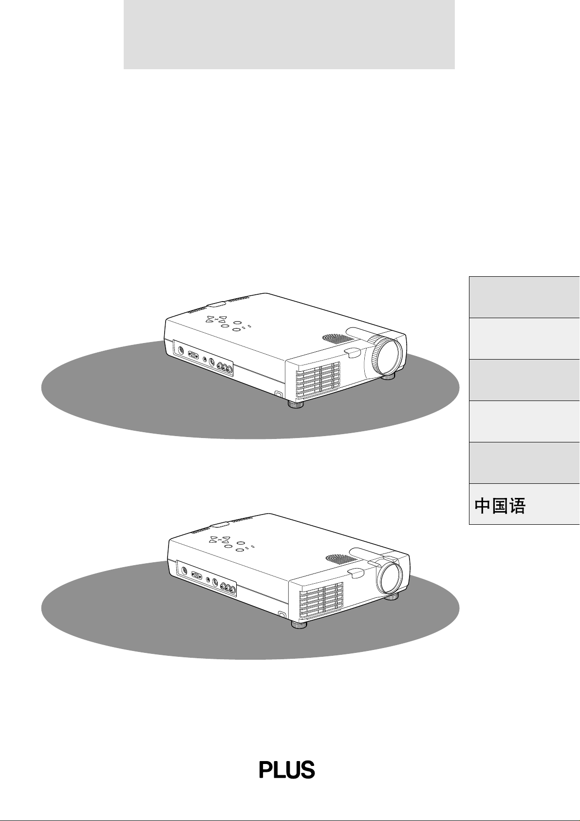
U2-1130/U2-1110/U2-811
DATA PROJECTOR
English
DOWN
–
S
U
E
+
P
L
E
C
T
M
E
N
U
E
N
S
T
T
E
A
R
T
U
S
P
O
W
E
R
M
O
U
S
E
R
G
B
I
N
P
C
A
U
D
I
O
S
-
V
I
D
E
O
V
I
D
E
O
A
U
D
L
/
I
M
O
O
N
O
R
Français
U2-1130
U2-1110*
U2-811
Deutsch
Italiano
Español
DOWN
–
S
U
E
+
P
L
E
C
T
M
E
N
U
E
N
S
T
T
E
A
R
T
U
S
P
O
W
E
R
M
O
U
S
E
R
G
B
I
N
P
C
A
U
D
I
O
S
-
V
I
D
E
O
V
I
D
E
O
A
U
D
L
/
I
M
O
O
N
O
R
* The U2-1130 is used for illustration purposes
in this manual unless otherwise specified.
Page 2

USER’S MANUAL
U2-1130/U2-1110/U2-811
English
Page 3
IMPORTANT SAFETY INFORMATION
Precautions
Please read this manual carefully before using your PLUS U2-1130/U2-1110/U2-811 Data Projector and keep the manual handy
for future reference.
Your serial number is located next to the main power switch on the back of the unit. Record it here:
CAUTION
TO PREVENT SHOCK, DO NOT OPEN THE CABINET. NO USER-SERVICEABLE PARTS INSIDE.
REFER SERVICING TO QUALIFIED PLUS SE RV I C E PE R S O N N E L .
WARNING
TO PREVENT FIRE OR SHOCK, DO NOT EXPOSE THIS UNIT TO RAIN OR MOISTURE. DO
NOT USE THIS UNIT’S GROUNDED PLUG
WITH AN EXTENSION CORD OR IN AN OUTLET UNLESS ALL THREE PRONGS CAN BE
FULLY INSERTED. DO NOT OPEN THE CABINET. THERE ARE HIGH-VOLTAGE COMPONENTS INSIDE. ALL SERVICING MUST BE
DONE BY QUALIFIED PLUS SERVICE PERSONNEL.
DOC Compliance Notice
This Class A digital apparatus complies with Canadian ICES-003.
Important Safeguards
RF Interference
WARNING
The Federal Communications Commission does not allow
any modifications or changes to the unit EXCEPT those
specified by PLUS Technologies in this manual. Failure to
comply with this government regulation could void your
right to operate this equipment.
This equipment has been tested and found to comply with
the limits for a Class A digital de vice, pursuant to Part 15 of
the FCC Rules. These limits are designed to provide
reasonable protection against harmful interference when
the equipment is operated in a commercial environment.
This equipment generates, uses, and can radiate radio
frequency energy and, if not installed and used in
accordance with the instruction manual, may cause
harmful interference to radio communications. Operation
of this equipment in a residential area is likely to cause
harmful interference in which case the user will be required
to correct the interference at his own expense.
Warning
This is a class A product. In a domestic environment this
product may cause radio interference in which case the
user may be required to take adequate measures.
These safety instructions are to ensure the long life of the unit and to prevent fire and shock. Please read them carefully and heed all w arnings.
Installation
• For best results, use the unit in a darkened room.
• Place the unit on a flat, level surface in a dry area away from dust
and moisture.
• Do not place the unit in direct sunlight, near heaters or heat
radiating appliances.
• Exposure to direct sunlight, smoke or steam can harm internal
components.
• Handle the unit carefully. Dropping or jarring can damage inter nal components.
• Do not place heavy objects on top of the unit.
• If installing the unit on the ceiling:
– The ceiling must be strong enough to support the unit and the
installation must be in accordance with any local building
codes.
– The unit must be installed by qualified PLUS service person-
nel.
Power Supply
• The unit is designed to operate on a power supply of 100 to 120
and 220 to 240 V 50/60 Hz AC. Ensure that your power supply
fits these requirements before attempting to use the unit.
• For PLUGGABLE EQUIPMENT, the socket-outlet shall be
installed near the equipment and shall be accessible.
• Handle the power cable carefully and avoid e xcessive bending. A
damaged cord can cause electric shock or fire.
• Disconnect the power cable (mains lead) from the power outlet
after using the unit.
Before disconnecting the power cable, make sure that the
POWER indicator lights in amber (not in green).
E – 2
Page 4
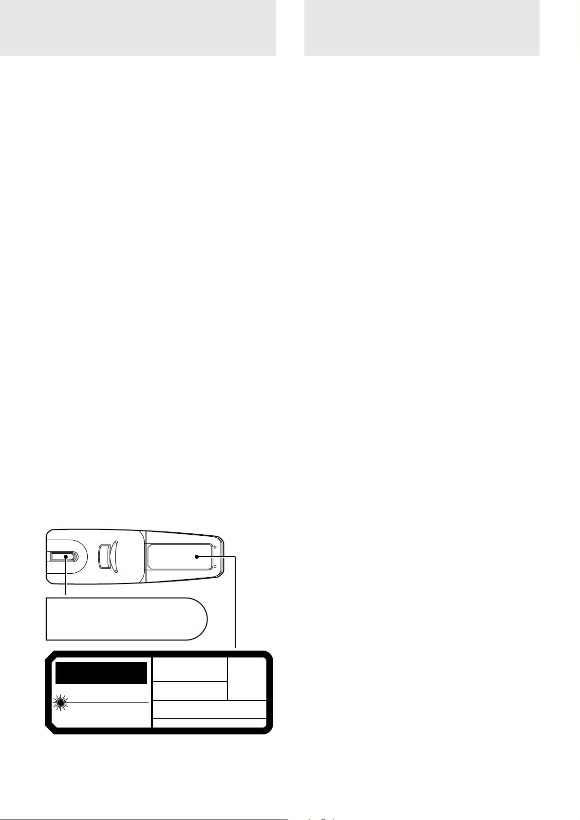
Table of contents
Cleaning
• Disconnect the power cable (mains lead) from the unit.
• Clean the cabinet of the unit periodically with a damp cloth. If
heavily soiled, use a mild detergent. Nev er use strong detergents
or solvents such as alcohol or thinner.
• Use a blower or lens paper to clean the lens, and be careful not to
scratch or mar the lens.
• Clean the ventilation slots and speaker grills on the unit
periodically using a vacuum cleaner . If accumula ted dust blocks
the ventilation slots, the unit will overheat, which may cause the
unit to malfunction.
Use a soft brush attachment when using the vacuum cleaner. Do
not use a hard attachment, such as a crevice tool, to prevent the
damage to the unit.
Lamp Replacement
• Be sure to replace the lamp when the Status indicator comes on.
If you continue to use the lamp after 1000 hours of usage, the
lamp will turn off.
Fire and Shock Precautions
• Ensure that there is sufficient ventilation and that vents are
unobstructed to prevent the buildup of heat inside the unit. Allow
at least 10 cm (3 inches) of space between the unit and walls.
• Prevent foreign objects such as paper clips and bits of paper from
falling into the unit. Do not attempt to retrieve any objects that
fell into the unit. Do not insert any metal objects such as a wire or
screwdriver into the unit. If something should fall into the unit,
immediately disconnect the power cable from the unit and have
the object removed by a qualified PLUS service person.
• Do not place any liquids on top of the unit.
• Do not look into the lens while the unit is on. Serious damage
to your eyes could result.
Carrying around
When carrying the unit around, please use the carrying case that
comes with it and, to protect the lens from scratches, always attach
the lens cap. Also, do not subject the unit to strong mechanical
shock.
Caution labels on bottom of the remote
controller
AVOID EXPOSURE
-LASER
RADIATION IS EMITTED
FROM THIS APERTURE
REMOTERADIACION LASER
CONTROL
MODEL:PRODUCTO LASER CLASSE 2
PLUS
CORPORATION
CAUTION
LASER RADIATION-
DO NOT STARE INTO BEAM
WAVE LENGTH:650nm
MAX OUTPUT:1mW
CLASS II LASER PRODUCT
NO MIRE AL RAYO
LASER-STRAHLUNG U2-870R
NICHT IN DEN STRAHL
BLICKEN! LASER KLASSE 2
RAYCNNEMENT LASER NE PAS
REGARDER DANS LE FAISCEAU
APPAREIL A LASER DE CLASSSE 2
EN60825-1:1994+A11:1996
IMPORTANT SAFETY INFORMATION................................... 2
Table of contents ........................................................................... 3
Basic information and preparations ........ 4
Features ......................................................................................... 4
Checking the supplied accessories ............................................... 4
Preparing the remote control ........................................................ 5
Parts and controls .......................................................................... 6
Installation..................................................................................... 9
Connections ............................................ 11
Connecting video equipment ...................................................... 11
Connecting a PC or Macintosh ................................................... 12
Using the remote control as a computer mouse
–Wireless mouse function........................................................... 14
Operation ................................................. 15
Using the unit .............................................................................. 15
Various functions while using the unit ....................................... 19
Menu operation....................................... 22
Menu structure ............................................................................ 22
Basic operation (Selecting the input source).............................. 23
Correcting the keystoning effect................................................. 24
Selecting a projection type ......................................................... 24
Selecting a menu language ......................................................... 24
Selecting the color system .......................................................... 24
Selecting the pointer type ........................................................... 25
Adjusting the volume .................................................................. 25
Selecting the background............................................................ 25
Adjusting the projected image from the computer .................... 26
Adjusting the picture elements ................................................... 28
Selecting t h e p i c t u r e type ........................................................... 28
Activating the power saving function......................................... 29
Quick-starting the unit ................................................................ 29
Activating the on-screen function............................................... 29
Checking hours of lamp usage.................................................... 30
Resetting to the factory settings ................................................. 30
Others ....................................................... 31
Troubleshooting .......................................................................... 31
When the STATUS indicator lights or flashes ........................... 32
Replacing the lamp cartridge ...................................................... 33
Specifications .............................................................................. 34
E – 3
Page 5
Basic information and preparations
Checking the
Features
Congratulations On Your Purchase Of The U21130/U2-1110/U2-811 Data Projector
The U2-1130/U2-1110/U2-811 is one of the very most spectacular
data projectors available today. The unit enables you to project
precise images up to 300 inches across (measured diagonally) from
your PC or Macintosh computer (desktop or notebook), VCR,
document camera, laser disc player, DVD player, etc.
The unit can be placed on a tabletop or cart, or permanently
mounted on the ceiling*. The unit can also be used to project
images from behind the screen.
* Installing the unit on the ceiling must be done by authorized PLUS
technicians. Consult your dealer for more information.
The other main features you’ll enjoy
• Compatible with following various color systems:
– NTSC (U.S. and Canada standard)
– PAL (Western Europe standard)
– SECAM (France and Eastern Europe standard)
– NTSC4.43 (Middle East standard)
• (U2-1130)
Superior brightness of 1300 ANSI lumens, the size of an A4
size/letter size piece of paper, and weighing only 2.6 kilograms/5.7 lbs.
(U2-1110/U2-811)
Superior brightness of 1100 ANSI lumens, the size of an A4
size/letter size piece of paper, and weighing only 2.5 kilograms/5.6 lbs.
Using TI’s Digital Mirror Device (DMD) and our own optical
design we have developed a geometric effect that increases the
light usage efficiency. By increasing the light usage efficienc y we
can better reproduce the three basic colors (RGB) required for
color reproduction on a single DMD. This means superior brightness, smaller size, and lighter weight.
• Sharp, clear images
There is no RGB color separation, and the spaces between the
individual pixels are not noticeable. That means sharp and clear
reproduction of small characters and figures. Take a closer look
and notice the difference in quality!
• Outstanding sharp, clear, 3D like images with vivid colors
when reproducing D VD video and other high picture-quality
data/video sources
Faithful gray scale reproduction makes for more natural image
displays. DVD and other high quality image sources bring out the
true display capacity of the unit.
• Screen not distorted to a trapezoid (keystoning) when projecting to the height of the line of vision
Because the projection position is already set to the height of the
line of vision, there is no keystoning effect.
Even when projecting above or under the height of the line of
vision, image distortion (if any) can be adjusted using the keystone correction function.
• (U2-1130, U2-1110)
Fully compatible with true XGA; support for SXGA using
advanced intelligent compression technology
The advanced intelligent compression technology enables these
projectors to present clear compression SXGA images without any
line omission.
(U2-811)
Fully compatible with true S-VGA; support for XGA using
advanced intelligent compression technology
The advanced intelligent compression technology enables it to
present clear compression XGA images without any line omission.
• A remote control that can operate the PC or Macintosh
The supplied remote control both operates the unit and acts as a
wireless mouse control to operate the PC or Macintosh connected to the unit.
• The compact and easy to carry cabinet with its contemporary
design complements any office, board room, or auditorium.
supplied accessories
Make sure your box contains everything listed below. If any
pieces are missing, contact your dealer.
Please save the original box and packing materials in case
you ever need to ship the unit.
The number of accessories is indicated in brackets.
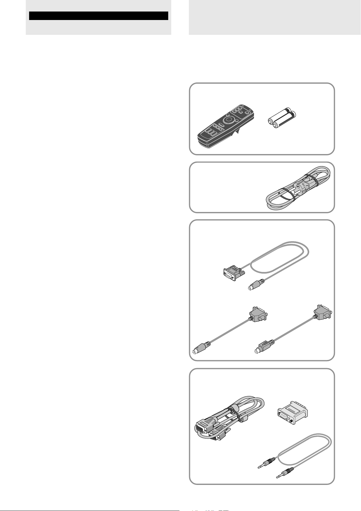
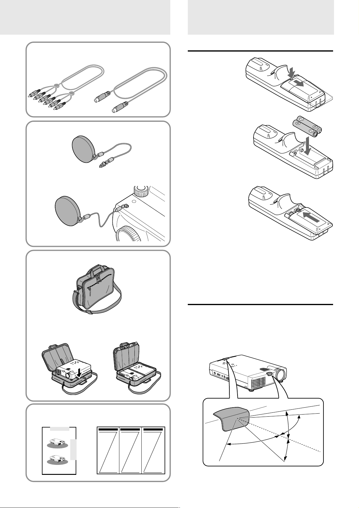
For remote control
Remote control [1] Batteries (size AA/R6) [2]
Power cable (mains lead)
(1.8 m/5.9 ft.) [1]
The shape of the plug varies
depending on the region where
the unit is purchased.
When using the remote control as computer
mouse
Serial mouse cable [1]
Mouse adapter
(for IBM PS/2) [1]
For computer connection
PC/Macintosh multicable
(1 m/3.3 ft.) [1]
Mouse adapter
(for Macintosh) [1]
Monitor adapter
(for Macintosh) [1]
PC audio cable
(1m/3.3 ft.) [1]
E – 4
Page 6
Preparing the
remote control
For video equipment connection
Audio video cable
(1 m/3.3 ft.) [1]
S-video cable
(1 m/3.3 ft.) [1]
Lens cap (attached to the lens of the unit) [1]
About the lens cap
The lens cap is fixed on the bottom of the
unit as shown in the illustration below.
Inserting the batteries
1 Press firmly and
slide the battery
cover off.
2 Insert the two
supplied batteries
(size AA/R6).
Ensure that the
polarities (+ and –)
of the batteries are
aligned correctly.
3 Slide the cover
back until it
snaps into place.
Carrying case [1]
How to use the carrying case
Packing the unit
USER’S MANUAL
(this manual) [1]
D
O
–
W
N
S
U
E
+
P
L
E
C
T
M
E
N
U
E
N
S
T
T
E
A
R
T
U
S
P
O
W
E
R
M
O
U
S
E
R
G
B
I
N
P
C
A
U
D
I
O
S
V
I
D
E
O
V
I
D
E
O
A
U
D
L
/
I
M
O
O
N
O
R
D
O
–
W
N
S
U
E
+
P
L
E
C
T
M
E
N
U
E
N
S
T
T
E
A
R
T
U
S
P
O
W
E
R
M
O
U
S
E
R
G
B
I
N
P
C
AU
D
IO
SVID
E
O
V
ID
EO
A
U
D
L
/
IO
M
O
N
O
R
Packing the accesories
Quick Start Guide [1]
Notes
• If the remote control gets wet, wipe it dry immediately.
• Avoid excessive heat and humidity.
• If you will not be using the remote control for a long time, remove the
batteries.
• Do not mix new and old or different types of batteries.
• There are operations that can only be carried out by remote control.
Handle the remote control carefully.
Remote control effective range
The remote sensors are located on the front and back of the unit.
The controllable range is 50 degrees horizontally and 30 degrees
vertically relative to a line that is at a right angle to the remote
sensor. And the distance between the point of the remote control
and remote sensor must be shorter than four meters (13 feet).
DOWN
–
S
U
E
+
P
L
E
C
T
M
E
N
U
E
N
S
T
T
E
A
R
T
U
S
P
O
W
E
MOUSE
R
RGB IN
PC AUDIO
S-VIDEO
VIDEO
AUDIO
L
/M
O
N
O
R
30˚
50˚
50˚
30˚
E – 5
Page 7
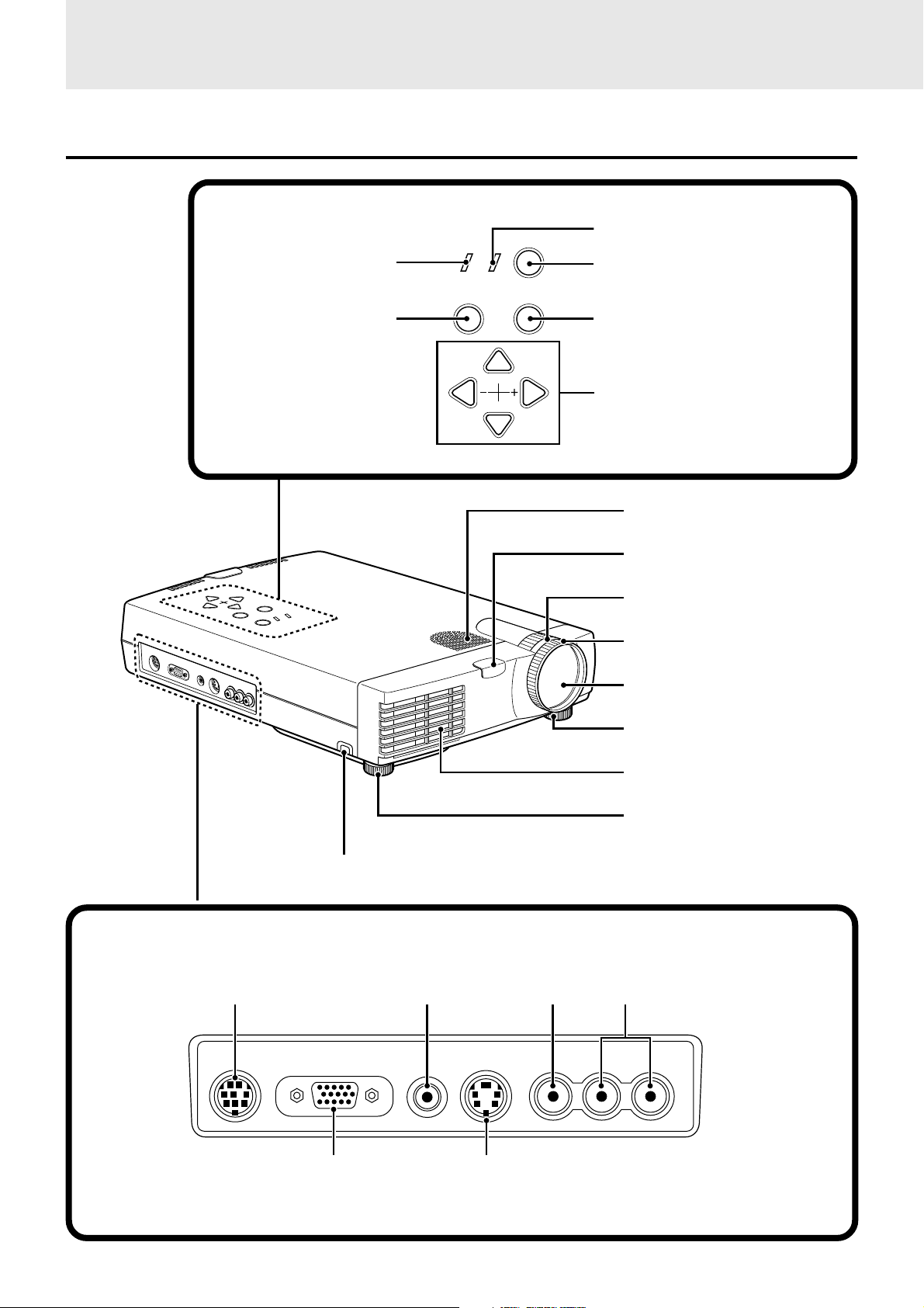
Parts and controls
For operational instructions, refer to the page indicated in brackets.
Top, front and side panel view
Control panel
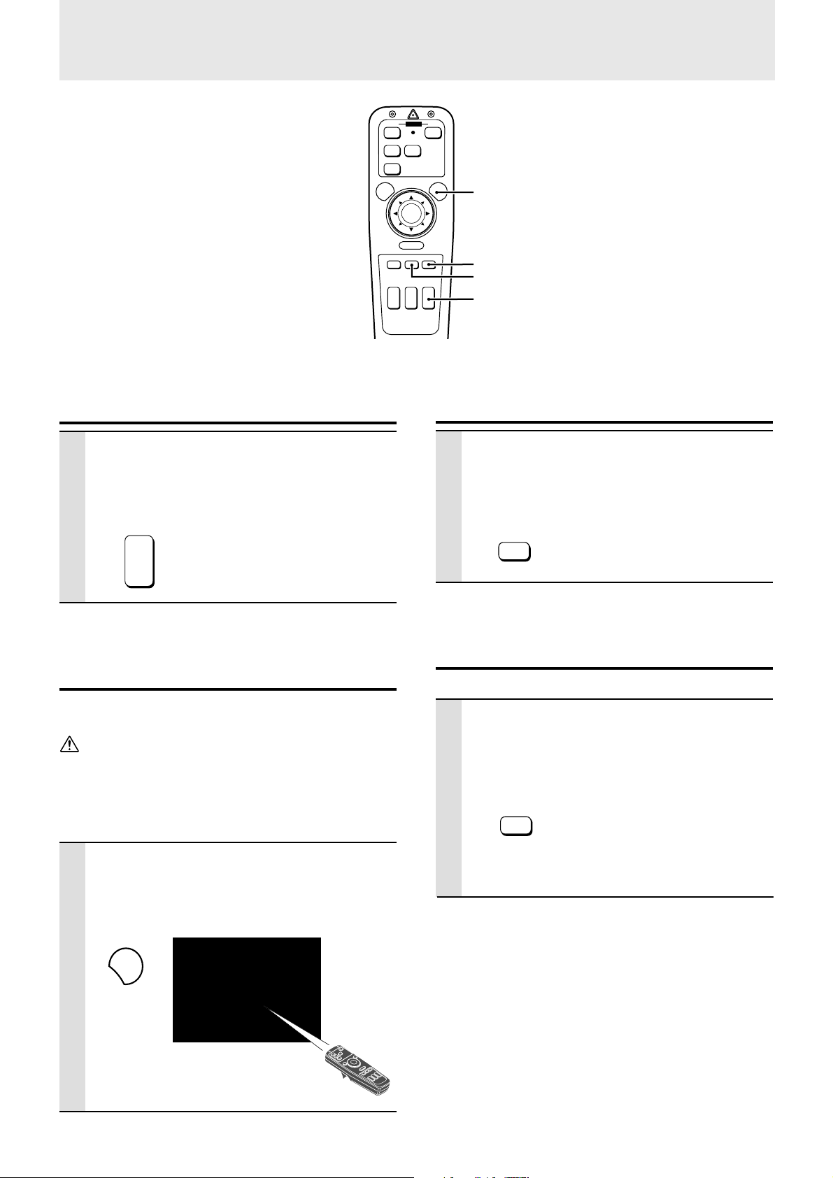
STATUS indicator [32]
STATUS
POWER
POWER indicator [15, 17]
POWER button [15, 17]
MENU
MENU button [23]
ENTER
ENTER button [23]
SELECT
UP
DOWN
SELECT UP/DOWN/+/– buttons [23]
Monaural speaker (1.0 W)
[11, 12]
Remote sensor [5]
D
O
–
W
N
S
U
E
+
P
L
E
C
T
M
E
N
U
E
N
T
E
R
M
O
U
S
E
R
G
B
IN
P
C
A
U
D
IO
S
-V
ID
E
O
V
ID
E
O
A
U
D
L
/M
IO
O
N
O
R
S
T
A
T
U
S
P
O
W
E
R
Zoom ring [16]
Focus ring [16]
Lens and Lens cap [5, 15]
Adjuster (left) [16]
Terminal Panel
MOUSE connector [14]
Adjuster button (right) [16]
PC AUDIO jack [12]
RGB IN connector [12]
VIDEO jack [11]
PC AUDIORGB INMOUSE AUDIOS-VIDEO VIDEO
S-VIDEO jack [11]
Ventilation slots
Adjuster (right) [16]
AUDIO L/MONO/R jacks [11]
L/MONO R
E – 6
Page 8
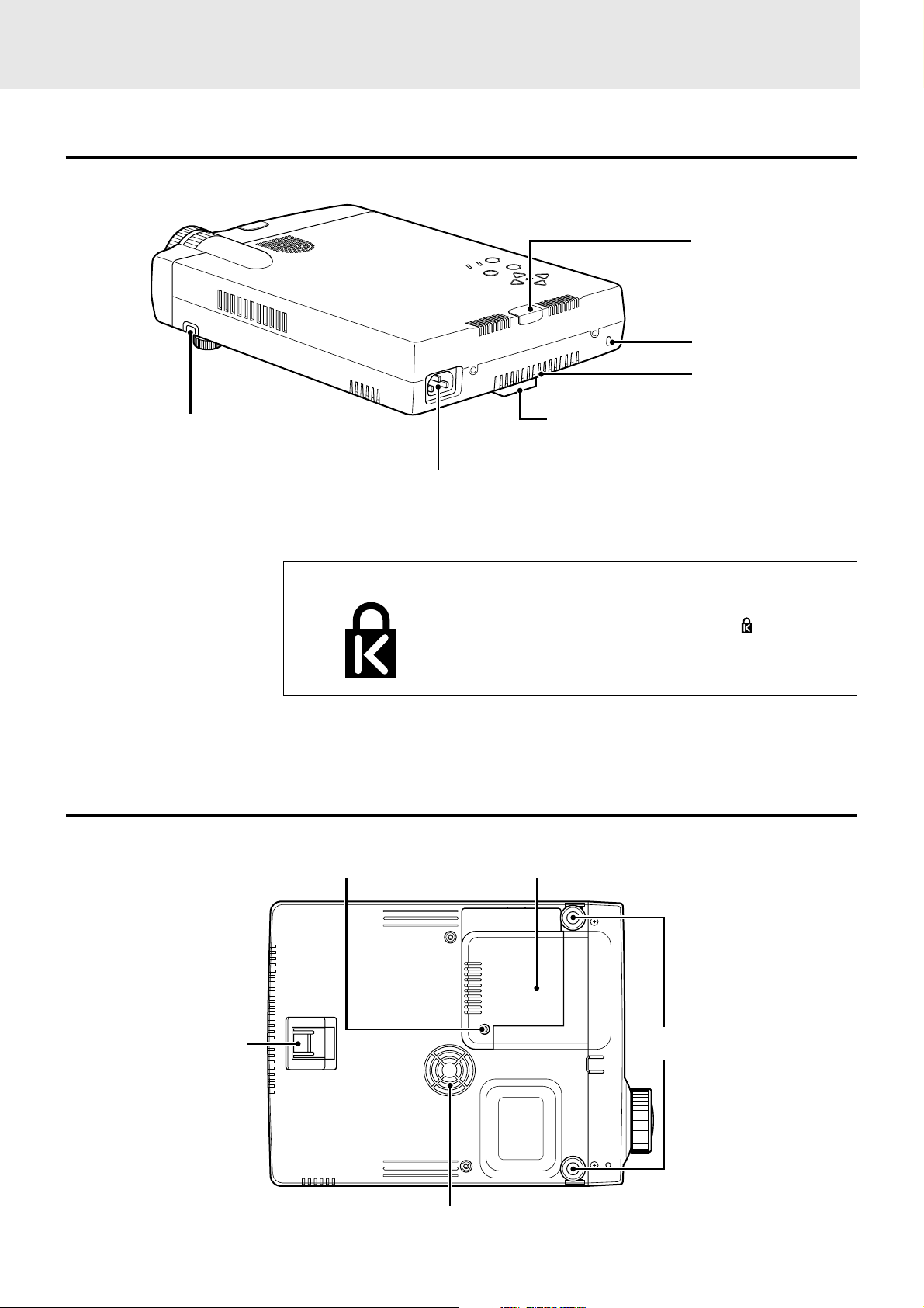
Rear and side panel view
Adjuster button (left) [16]
AC IN terminal [15]
Built-in Security Slot
R
E
W
O
P
S
U
T
A
T
S
R
E
T
N
E
U
N
E
M
T
C
E
L
P
+
E
U
S
N
W
–
O
D
Remote sensor [5]
Built-in security slot
[see below]
Ventilation slots
Rear adjuster [16]
This security slot supports the MicroSaver® Security
System. MicroSaver® is a registered trademark of
Kensington Microware Inc. The logo is trademarked and owned by Kensington Microware Inc.
Bottom
Rear adjuster [16]
Lamp cover [33]Lamp cover securing screw [33]
Front adjusters [16]
Ventilation slots
(Continued on next page.)
E – 7
Page 9
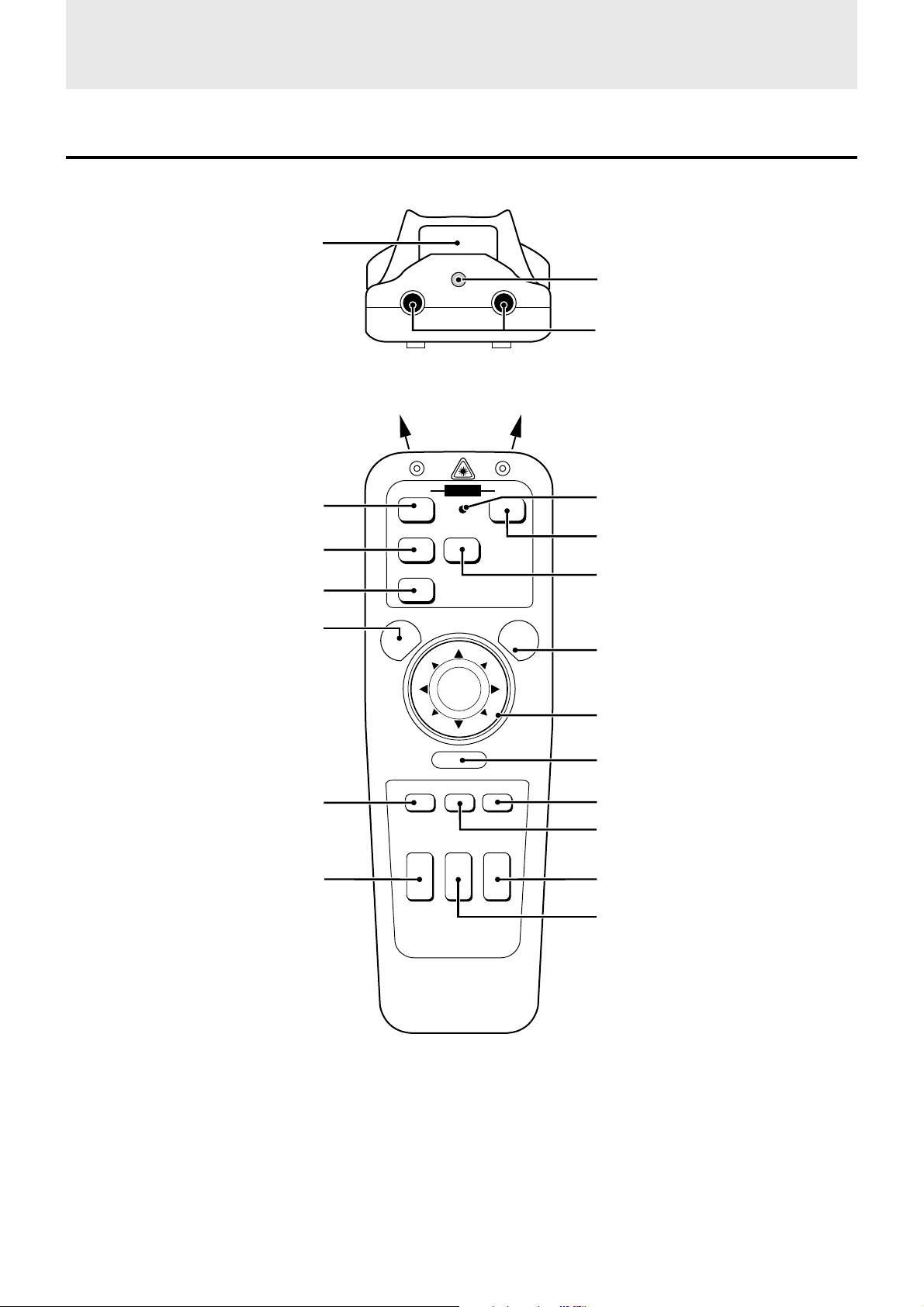
Parts and controls (continued)
Remote control
L-CLICK button [14, 23]
OFF ON
POWER
POWER OFF button [17, 30]
VIDEO
S-VIDEO
VIDEO button [15]
RGB
RGB button [15]
MENU
MENU button [23]
LASER
Laser pointer [19]
(Laser aperture)
Infrared transmitter [5]
LED
Lights when any button is pressed.
POWER ON button [15, 30]
S-VIDEO button [15]
LASER button [19]
POINTER button [20, 21]
MAGNIFY +/– button [20, 21]
–
R-CLICK
POINTER MUTE FREEZE
MAGNIFY KEYSTONE VOLUME
+
+
–
–
PLUS
+
Cursor key [14, 20, 21, 23]
R-CLICK button [14, 23]
FREEZE button [19]
MUTE button [19]
+
–
VOLUME +/– button [19]
KEYSTONE +/– button [16]
E – 8
Page 10
Installation
The distance from the unit lens to the screen determines to the size of the projected image, therefore, you need to consider the place where you
set up the unit and screen before making connections. You also need to consider the screen size and height of the unit and screen as other
important factors.
Tip
A non-glossy wall may be used as a substitute for a screen.
WARNING
• Carrying the unit
Always carry the unit in the carrying case. Ensure that the power cable and any other cables connecting to video sources are disconnected
before moving the unit. When moving the unit or when it is not in use, cover the lens with the lens cap.
• Only use the unit on a solid flat level surface. If the unit falls to the ground, you may be injured and the unit may severely be damaged.
• Do not use the unit where temperatures vary greatly. The unit must be used at temperatures between 5°C (41°F) and 35°C (95°F).
• Do not expose the unit to moisture, dust, or smoke. This will harm the screen image.
• Ensure that you have adequate ventilation around the unit to allow heat dissipation. Do not cover the vents on the bottom or the side of the
unit.
Positioning the unit
The projected image becomes larger as the distance between the unit and screen increases. The minimum image size is about 25 inches
diagonally at a distance of about 1.2 m (approx. 3.9 feet) and the maximum size is approx. 300 inches at a distance of 12.3 m (approx. 40.4
feet) from the screen. Use the following information when you fix the position of the unit.
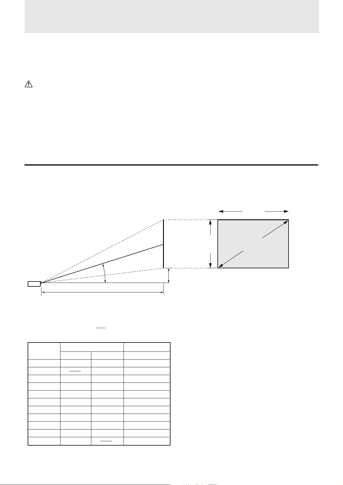
Projecting distance and image size
Screen
11 to 15 degrees
(represented as “L” in the table and chart below)
• Horizontal projection position Lens centered left to right
• Vertical projection position (U2-1130)
Screen size Projection distance (L) Dimension (H) cm
Inches m / feet m / feet cm / inch
25 1.2 / 3.9 7.4 / 2.9
40 1.6 / 5.2 1.9 / 6.2 11.9 / 4.7
60 2.4 / 7.9 2.9 / 9.5 17.8 / 7.0
80 3.2 / 10.5 3.9 / 12.8 23.7 / 9.3
100 4.0 / 13.1 4.9 / 16.1 29.7 / 11.7
120 4.9 / 16.1 5.8 / 19.0 35.6 / 14.0
150 6.0 / 19.7 7.3 / 24.0 44.5 / 17.5
200 8.1 / 26.6 9.8 / 32.2 59.3 / 23.3
240 9.8 / 32.2 11.7 / 38.4 71.2 / 28.0
300 12.3 / 40.4 89.0 / 35.0
Projection distance
Wide (W)
Telephoto (T)
Both W & T
Screen
width
Screen
Height
Distance from center of lens to lower edge of screen
(represented as “H” in the table and chart below)
Screen size
(diagonal)
(Continued on next page.)
E – 9
Page 11
Installation (continued)
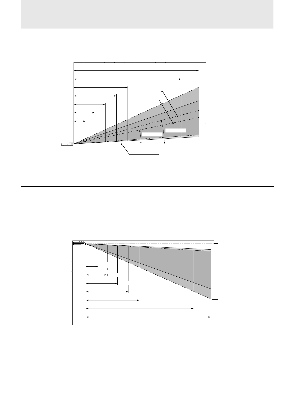
• Projecting distance and image size
Projection distance
0123456789101112 (m)
0 3.3 6.6 9.8 13.1 16.4 19.7 23.0 26.2 29.5 32.8 36.1 39.4 (feet)
Tele. – Wide
250″ – 300″
Diagonal image size (inch)
200″ – 240″
100″ – 120″
80″ – 96″
60″ – 72″
40″ – 48″
25″ – 30″
4.9m / 16.1 feet
3.9m / 12.8 feet
2.9m / 9.5 feet
1.9m / 6.2 feet
1.2m
3.9 feet
12.3m / 40.4 feet
9.8m / 32.2 feet
Image center in
wide mode
Image center
in telephoto
mode
12.7˚ – 12.1˚
15.1˚ – 14.5˚
Center of lens
Height of the
projecting image
6m / 19.7 feet
5m / 16.4 feet
4m / 13.1 feet
3m / 9.8feet
2m / 6.6 feet
1m / 3.3 feet
0m / 0 feet
Using the ceiling mounting fixtures
When using the ceiling hanging fixtures, select “FRONT/CEILING” in “PROJECTION” of “SETTING MENU” (see pages 17 and 24).
Note
Installing the unit on the ceiling must be performed by qualified PLUS service personnel. Contact your PLUS dealer for more information. Never
attempt to install the unit yourself.
Projection distance
0123456789101112 (m)
Height of the
projecting image
1m / 3.3 feet
2m / 6.6 feet
3m / 9.8feet
4m / 13.1 feet
5m / 16.4 feet
6m / 19.7 feet
0 3.3 6.6 9.8 13.1 16.4 19.7 23.0 26.2 29.5 32.8 36.1 39.4 (feet)
1.2m / 3.9 feet
(25 to 30″)
1.9m / 6.2 feet
2.9m / 9.5 feet
(40 to 48″)
3.9m / 12.8 feet
4.9m / 16.1 feet
(60 to 72″)
(80 to 96″)
9.8m / 32.2 feet
(100 to 120″)
12.3m / 40.4 feet
(200 to 240″)
(250 to 300″)
Center of lens
151 to 154 mm/ 0.5 feet
In telephoto mode
4,712 to 4,742 mm/
15.5 to 15.6 feet
In wide mode
5,613 to 5,660 mm/
18.4 to 18.6 feet
E – 10
Page 12
Connections
Connecting video equipment
You can connect up to two pieces of video equipment to the unit following the illustrations below.
• You can switch the input source (picture) to VIDEO or S-VIDEO when you connect two pieces of equipment.
(The S-VIDEO connection provides more vivid color and higher resolution compared to the VIDEO connection.)
• You can output the sound of only one component through the unit speaker even when two components are connected.
Before connecting
• Turn off the components that are to be connected.
• The unit and computer will be turned on in “Using the unit” on page 15. Do not turn on either the computer or the unit until you read this
section.
• Please also refer to the manual of the video component to be connected.
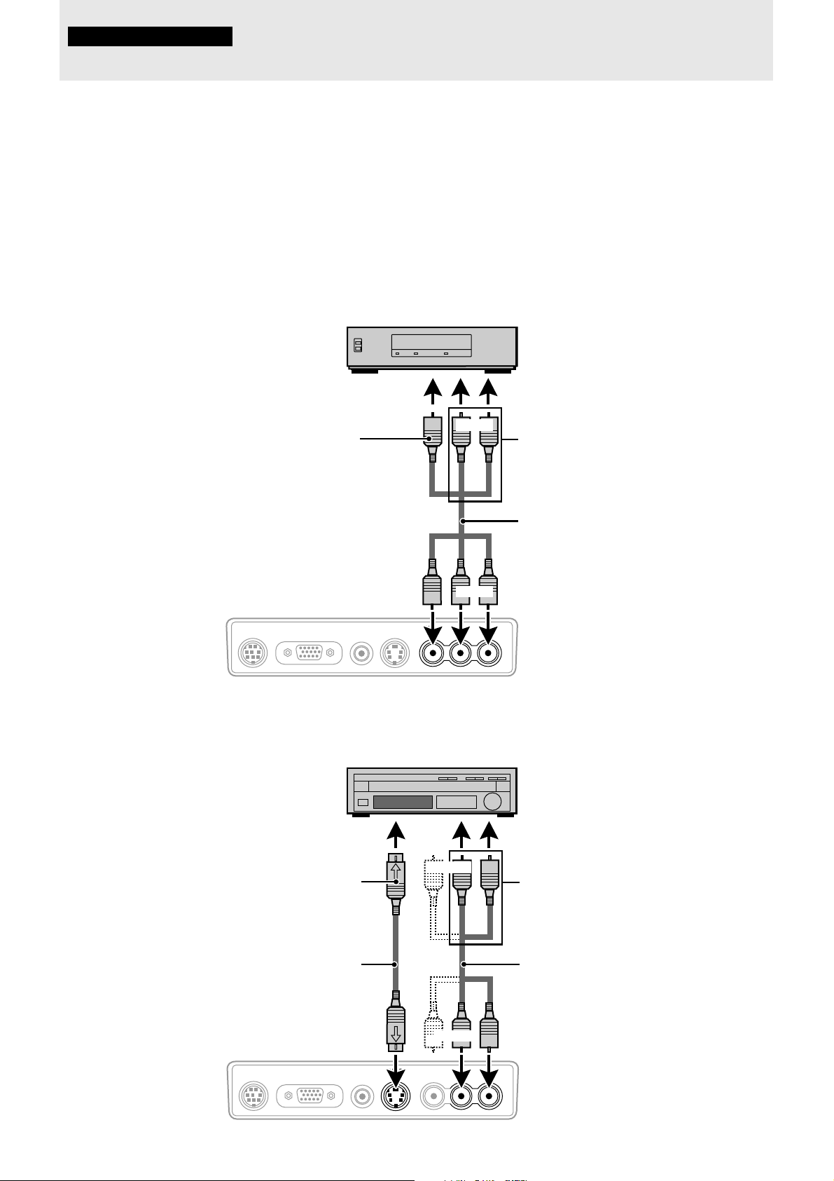
Connection to the VIDEO jack
of the unit
To video output jack
The unit's terminal panel
DVD player, laser disc play er,
VCR, document camera, etc.
(L) (R)
Yellow
Yellow
PC AUDIORGB INMOUSE AUDIOS-VIDEO VIDEO
White
White
(L) (R)
L/MONO R
Red
To audio output jacks
Audio/video cable (supplied)*
Red
* If the equipment to be connected to the unit is a
monaural type, connect to the L/MONO jack of
the unit.
Connection to the S-VIDEO jack
of the unit
To S-video output jack
The unit's terminal panel
S-video cable
(supplied)
DVD player, laser disc player,
VCR, document camera, etc.
(L)
(R)
White Red
White
(L) (R)
PC AUDIORGB INMOUSE AUDIOS-VIDEO VIDEO
L/MONO R
E – 11
To audio output jacks
Audio/video cable (supplied)*
Red
* If the equipment to be connected to the unit is a
monaural type, connect to the L/MONO jack of
the unit.
Page 13
Connecting a PC or Macintosh
Connecting a PC or Macintosh to the unit will enable you to project your computer screen images for impressive presentations.
• The following display standards are supported:
VGA 640×480 for graphics SuperVGA 800×600
VGA 640×350 for graphics XGA 1024×768 (U2-1130/U2-1110 only)
VGA 720×350 for text Macintosh at 640×480
VGA 640×400 for graphics Macintosh at 832×624
VGA 720×400 for text Macintosh at 1024×768 (U2-1130/U2-1110 only)
• U2-1130 A PC, Macintosh, or computer equipped with an XGA adapter or compatible graphics adapter can easily be connected.
U2-1110
(U2-811) A PC, Macintosh, or computer equipped with an S-VGA adapter or compatible graphics adapter can easily be connected.
U2-1130
• If your PC does not support XGA you will need to install an XGA graphics board. Consult your computer's owner's manual for
U2-1110
(U2-811) If your PC does not support S-VGA/VGA you will need to install an S-VGA/VGA graphics board. Consult your computer’s
Notes
• Refer to the owner's manual supplied with your computer for more information about the video output requirements of the computer and any special
identification or configuring required by the projector image and monitor.
U2-1130
• Some Macintosh PowerBooks may need to set the mirroring to off to output 1024 × 768 dot signals. Please consult your PowerBook
U2-1110
(U2-811) Some Macintosh PowerBooks may need to set the mirroring to off to output 800×600 dot signals. Please consult your PowerBook
Before connecting
• Turn off the computer that is to be connected.
• The unit and computer will be turned on in “Using the unit” on page 15. Do not turn on either the computer or the unit until you read this
section.
• Please also refer to the manual of the computer to be connected.
your XGA configuration. If you need to install a new board, refer to the manual supplied with your new graphics board for
installation instructions.
owner’s manual for your S-VGA configuration. If you need to install a new board, refer to the manual supplied with your new
graphics board for installation instructions.
manual or computer dealer for details.
manual or computer dealer for details.
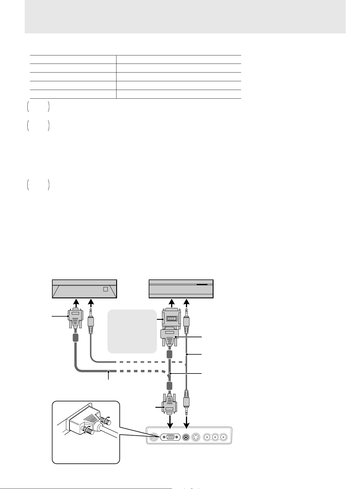
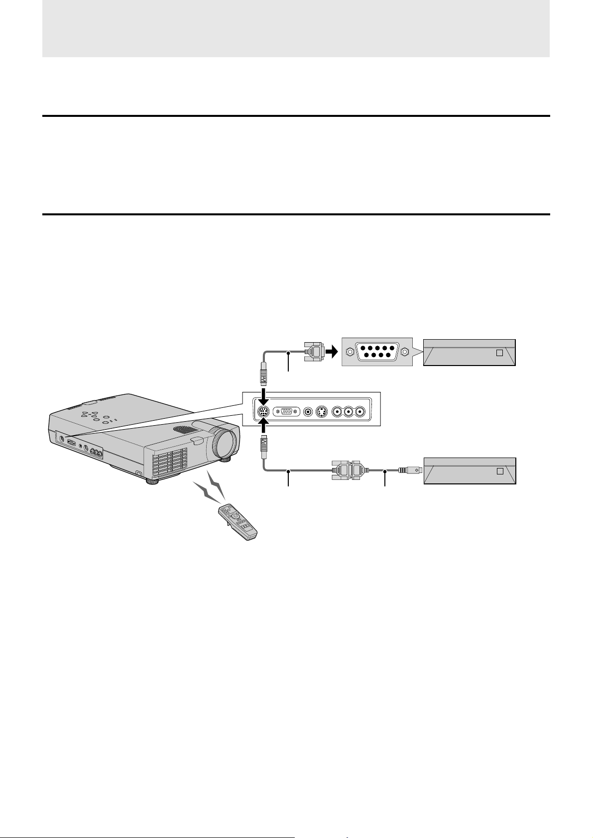
Mini D-Sub
15-pin
connector
IBM PC/AT compatible machine or
Macintosh with Mini D-Sub 15-pin
connector
To PC’s audio jack
Monitor adapter for
Macintosh
You may need to
change the DIP switch
setting depending on
the machine to be
connected. See next
page.
PC/Macintosh multicable
(supplied)
Plug the cable connector
into the RGB IN connector
securely and tighten the
screws.
Macintosh desktop computer
Mini D-Sub
15-pin
connector
To Macintosh's audio jack
Mini D-Sub 15-pin connector
PC audio cable
(supplied)*
PC/Macintosh multicable
(supplied)
* When VIDEO or S-VIDEO is selected as the input source,
the sound from the AUDIO L/MONO /R jacks will be
output.
When RGB is selected as the input source, the sound from
the PC AUDIO jack will be output.
PC AUDIORGB INMOUSE AUDIOS-VIDEO VIDEO
L/MONO R
The unit's
terminal panel
E – 12
Page 14
Note on the PowerBook connection
Depending on the model of your PowerBook, the additional Apple video cable adapter may be required with the above connection.
Video cable adapter
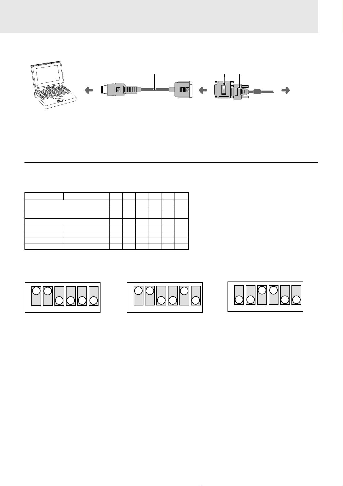
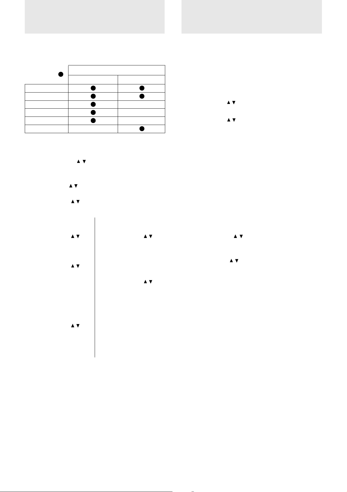
Modifying the DIP switch setting (for Macintosh)
Modify the DIP switch setting according to the DIP switch setting table below.
DIP switch setting (● = ON)
MONITOR RESOLUTION 123456
MULTIPLE SCAN 21 ●● ●
MULTIPLE SCAN 17 ●● ●
MULTIPLE SCAN 16 ●● ●●
VGA/S-VGA ●●
21″ COLOR 1152×870 ●●●●
19″ COLOR 1024×768 ●●
16″ COLOR 832×624 ●●
13″ COLOR 640×480 ●●
Monitor adapter
(supplied)
Mini D-Sub 15-pin connector
(supplied)
To the Data Projector
Inch 13
ON
123456
MULTIPLE SCAN 17
ON
123456
VGA/S-VGA/XGA/SXGA
(U2-1130/U2-1110 only)
ON
123456
E – 13
Page 15
Using the remote control as a computer
mouse – Wireless mouse function
The supplied remote control enables you to operate the computer’s mouse functions by connecting the computer to the MOUSE connector of
the unit. It is a great way to control your computer-generated presentations.
How does the remote control operate the computer?
• The cursor key on the remote control operates the computer mouse functions.
• If a computer running Windows is connected, the L-CLICK button on the remote control operates as the computer mouse left click button
and the R-CLICK button as the computer mouse right click button.
• If a Macintosh computer is connected, the L-CLICK and R-CLICK buttons operate in the same way as the computer mouse click button.
• While the menu is displayed on the screen (see page 22, 23), the cursor key , L-CLICK and R-CLICK buttons will operate to control the menu.
Connecting the computer to the MOUSE connector of the unit
Before connecting
• Turn off the computer, then remove the current mouse.
• The unit and computer will be turned on as described in “Using the unit” on page 15. Do not turn on either the computer or the unit until you
read that section.
• Please also refer to the manual of the computer to be connected.
How to connect to the IBM PC/AT
computer
Use the supplied serial mouse cable to connect
the MOUSE connector of the unit and the 9-pin
serial port (COM1/COM2/COM3/COM4) of
the computer.
How to connect to the IBM PS/2 or
Macintosh computer
Use the supplied serial mouse cable and mouse
adapter (for IBM PS/2 or Macintosh).
1 Connect the serial mouse cable and mouse
adapter.
2 Connect the other end of the serial mouse
cable to the MOUSE connector of the unit.
3 Connect the other end of the mouse adapter
to the mouse port of the computer.
Serial mouse cable (supplied)
To the MOUSE connector
PC AUDIORGB INMOUSE AUDIOS-VIDEO VIDEO
To the MOUSE connector
Serial mouse cable
(supplied)
9-pin serial port
L/MONO R
IBM PC/AT
IBM PS/2 or Macintosh
Mouse adapter for IBM PS/2 (supplied) or
Mouse adapter for Macintosh (supplied)
E – 14
Page 16

Operation
Using the unit
Before starting
• Remove the lens cap from the lens. Please keep it because it must
be replaced after use.
• Don’t use the unit in a bright room and don’t expose the screen to
direct sunlight or other strong light sources.
1 Connect the supplied power cable to the
unit, then to the wall outlet (the mains).
The POWER indicator on top of the unit lights in
amber.
STATUS
Lights in amber
(Standby)
Power cable
(supplied)
1
POWER
POWER
STATUS
MENU
ENTER
+
UP
SELECT
–
DOWN
2
3 T urn on the connected source (computer,
VCR, DVD player, etc.).
If you use a video component, start playback for
screen/image adjustment.
4 Press either VIDEO, S-VIDEO, or RGB to
select the input source.
You can also select the input source with the
menu operation (see page 23).
OFF ONPOWERPOWER
VIDEO
S-VIDEO
RGB
Notes
• If the blue or black screen (the background type differs
depending on the “BACKGROUND” setting. See page 25.)
is projected, check the following:
– Is the source properly connected to the unit?
– Is the source component or computer turned on?
– Are the video signals coming to the unit?
• The video resolution of the connected computer can be
changed. See page 18.
2 Press POWER ON on the remote control,
or POWER on top of the unit, to turn on
the unit.
The POWER indicator on top of the unit turns to
green and starts flashing.
It takes one minute for the unit to be ready f or use.
Wait until the indicator stops flashing and lights
steadily in green.
POWER
OFF ONPOWERPOWER
VIDEO
S-VIDEO
RGB
Note
While the POWER indicator is flashing, the unit doesn’t turn
off even if you press POWER OFF on the remote control, or
POWER on the unit.
Tip
If you set “ AUTO ST ART” to “ON” in the menu (see page 29),
the unit will turn on automatically after connecting the power
cable in step 1.
Green light flashes
(About one minute)
↓
Then lights steadily
in green
5 Adjust the position and height of the unit.
Move the unit to the position where the projected
image is horizontally centered to the screen.
• When the projected image is offset
horizontally
Adjust the position of the unit so that the unit is
square to the screen.
View from the top
• When the pr ojected ima ge is offset ver-
tically
Adjust the height balance of the unit with the
adjusters. See next page.
Side view
(Continued on next page.)
Screen
Screen
E – 15
Page 17
Using the unit (continued)
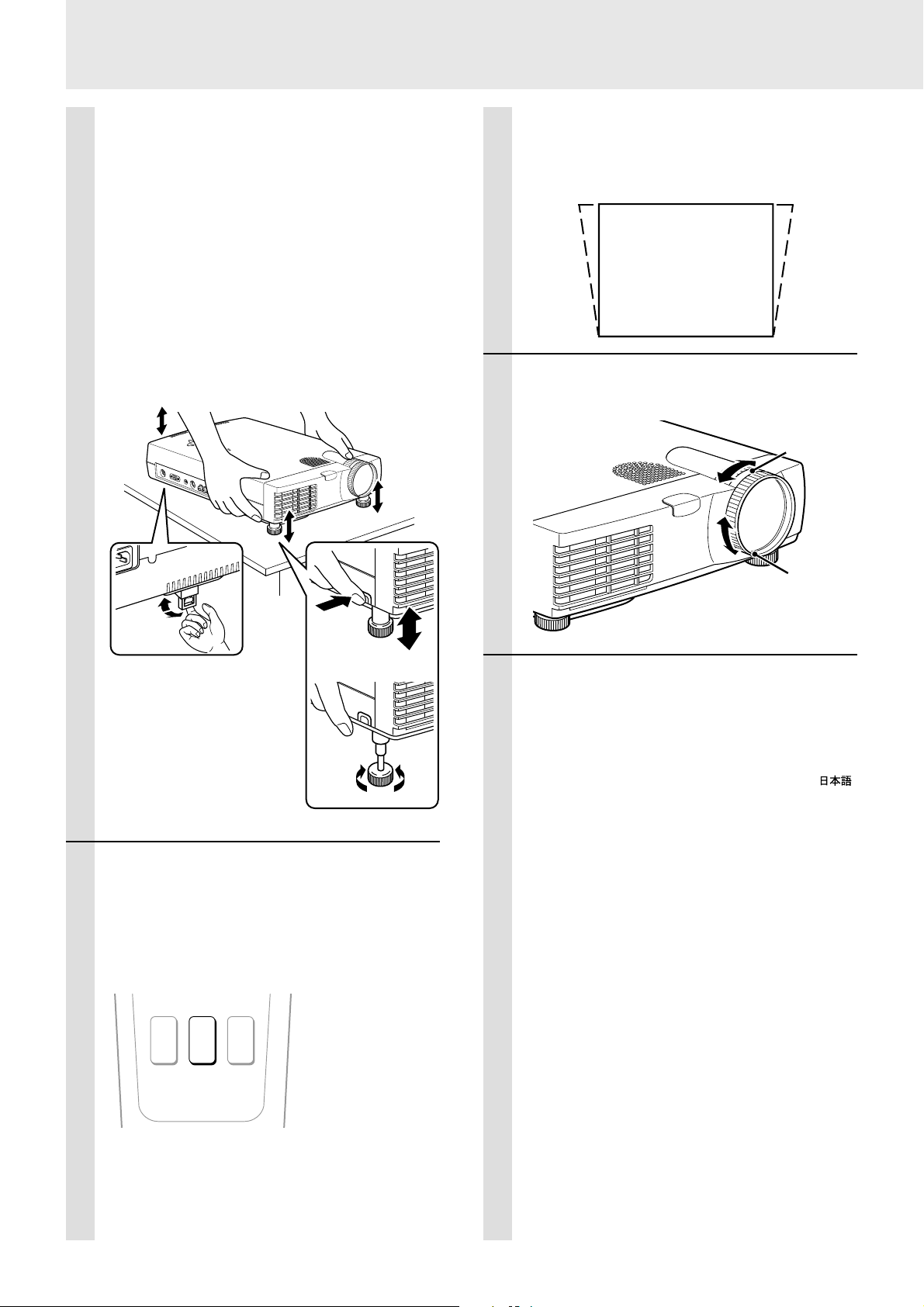
Using the adjusters to adjust the height balance
There are two front adjusters and one rear adjuster.
1 If you need to lower the position of the projected
image, pull out the leg of the rear adjuster.
2 Hold the front sides of the unit, then adjust the
height of the projected image.
While adjusting the height, the rear adjuster should remain
on the table.
3 Press the left and right buttons by the front ad-
justers at the same time to loosen the adjuster
legs.
The front adjuster legs will loosen and be extended.
4 Release the buttons to fix the position of the front
adjuster legs.
5 To fine-adjust the height and balance, turn each
foot of the front adjuster legs.
D
O
–
W
N
S
U
E
+
P
L
EC
T
M
E
N
U
E
NT
S
TA
E
R
T
US
P
O
W
E
R
M
2
O
U
S
E
R
G
B
IN
P
C
A
U
D
IO
S
-
V
ID
E
O
V
ID
E
O
A
U
D
L
/M
IO
O
N
O
R
Adjusting the distorted picture
The upper distortion of the picture will be corrected as you see
the illustration below.
The menu screen shape is not changed by the keystone
correction even when displayed.
→←
7 Adjust the image size with the zoom ring,
then adjust the focus with the focus ring.
Zoom ring
Down
1
Up
3
4
Up
Down
5
6 (If the vertical offset cannot be adjusted
completely with the adjusters)
Press KEYSTONE + or – to correct the
offset (keystoning) image.
You can also correct the keystoning effect with
the menu operation (see page 24).
MAGNIFY KEYSTONE VOLUME
+
+
+
Focus ring
8 Change the unit setting to suit the
method and source selected in step 4.
The following settings can be made using the
menu operation.
The menu can be displayed in English, Deutsch,
Français, Italiano, Español, Svenska, or .
(The standard setting is English.) See page 24.
• For basic menu operation, see page 23.
• To see an overview of the menu structure, see
page 22.
• Select the type of projection
If the projected image is horizontally reversed
or upside down, change the projection type.
See page 24.
• When the input source is VIDEO or S-
VIDEO
Select the color system. See page 24.
–
–
–
PLUS
Note
The maximum correction value is 29° including the optical
correction value.
• When the input source is RGB
Adjust the projected image from the computer.
The resolution most suitable for the incoming
signals is automatically selected.
However, if any ver tical banding, noise, dot
interference, or crosstalk appears on the
screen, manually adjust “PICTURE ADJ ,” then
“FINE PICTURE” using the menus. See page
27.
E – 16
Page 18
The horizontal and vertical positions of the
image can also be adjusted manually. See
page 27.
If you have set “A UT O MODE” to “OFF” to carry
out the above described adjustments (see
page 27 for details), you can choose to project
the image at the original size of the incoming
signal resolution. (Normally, the image is
enlarged or reduced to the most suitable size
automatically.) See page 27.
After using the unit
1 Press POWER OFF on the remote control,
or POWER on the unit, for two to three
seconds.
When you have turned off the unit, the POWER
indicator will start flashing then turn to amber in
one minute.
Never disconnect the power cable while the
POWER indicator is flashing.
9 Adjust the picture elements (see page
28), then select the picture type
according to the video content (see page
28).
10
Start using the unit.
The following functions are a vailable while using
the unit:
• Adjusting the volume of the unit's speaker
(see pages 19 and 25),
• Using the laser pointer (see page 19),
• Turning off the image and muting the sound
temporarily (see page 19),
• Freezing a moving picture (see page 19),
• Enlarging the picture (see page 20), and
• Enlarging the picture after selecting the
portion you wish to enlarge (see page 21).
Note
If “POWER OFF” is set to “ON” (see page 29), the image will
be turned off if the unit has been left unoperated for five
minutes with an RGB input source.
If the image is suddenly turned off while projecting a computer
image, the computer’s screen saver or power management
function may be activated.
POWER
OFF ONPOWERPOWER
VIDEO
S-VIDEO
RGB
Notes
• Neither POWER ON on the remote control nor POWER on
the unit operate while the POWER indicator is flashing.
• Wait at least one minute before turning on the unit again.
POWER ON on the remote control or POWER on the unit
may not operate if you try to turn on the unit again within one
minute after turning off the unit.
Green light flashes
(About one minute)
↓
Then lights steadily
in amber
2 After the POWER indicator stops flashing
and turns to amber , disconnect the po wer
cable from the wall outlet, then from the
unit.
The POWER indicator goes out.
Note
Hold the plug when disconnecting the power cable. Never pull
the cord.
E – 17
(Continued on next page.)
Page 19

Using the unit (continued)
Changing the computer’s video
resolutions
Depending on your computer's graphics capability, you may be
able to select one of several resolutions. Generally a computereither a PC or Macintosh- with 1 MB VRAM will generally run:
640 × 480 at 16.7 million colors (24 bit Truecolor)
800 × 600 at 65,000 colors.
1024 × 768 at 256 colors.
As the resolution increases, the number of colors you can run
decreases. With 2 MB VRAM a computer will generally run:
640 × 480 at 16.7 million colors (24 bit Truecolor).
800 × 600 at 16.7 million colors (24 bit Truecolor).
1024 × 768 at 65,000 colors.
1280 × 1024 at 256 colors.
Windows 98/Windows 95
There are two methods you can use to change your resolution.
Method 1
1 Move your cursor to the background image and click.
2 In the “Properties” menu, select “Settings.”
3 Change your resolution and click “OK.”
4 You may be asked to reboot for the changes to take effect,
or a message may appear saying that “Windows is about
to resize your display.” You’ll be asked if you want to
keep your settings. Select “Yes.”
Notebook computers and resolution
standards
(U2-1130/U2-1110)
The unit is designed to project industry standardized video such as
VESA (Video Electronics Standards Association) or XGA
(eXtended Graphics Array). Notebook computers do not use industry standards. They use whatever timing is necessary to ma tch their
local LCD display. The end result is typically not standard. By
turning off your notebook's display, the timing parameters are a bit
more like the real VESA or XGA signal.
(U2-811)
The unit is designed to project industry standardized video such as
VESA (Video Electronics Standards Association) or VGA (Video
Graphics Array). Notebook computers do not use industry standards. They use whatever timing is necessary to match their local
LCD display. The end result is typically not standard. By turning off
your notebook display, the timing parameters are a bit more lik e the
real VESA or VGA signal.
Method 2
1 Click on your “My Computer” icon.
2 Open “Control Panel” and select “Display.”
3 Change your resolution and click “OK.” after the new
resolution is selected.
4 You may be asked to reboot for the changes to take effect,
or a message may appear saying that “Windows is about
to resize your display.” You’ll be asked if you want to
keep your settings. Select “Yes.”
Windows 3.1
1 Click on the “Main” icon and open “Control Panel.”
2 Select “Change System Settings” and click on “Option.”
3 Choose “Change Display Settings.”
4 Select the resolution you want.
5 Choose the current or desired drive.
6 Restart Windows for the changes to take effect.
Macintosh
1 Under the Apple menu, select “Control Panels” and open
“Monitors.”
2 Click and open “Options.”
3 Select your new resolution and click “OK.”
E – 18
Page 20
Various functions while using the unit
OFF ONPOWER
VIDEO
S-VIDEO
RGB
MENU
–
POINTER MUTE FREEZE
MAGNIFY KEYSTONE V OLUM E
+–+
PLUS
R-CLICK
LASER
LASER button
+
FREEZE button
+
–
–
MUTE button
VOLUME +/– button
Adjusting the volume of the unit's
speaker
Press VOLUME + to increase the volume
or – to decrease.
The volume can also be adjusted using the menu
(see page 25).
VOLUME
+
–
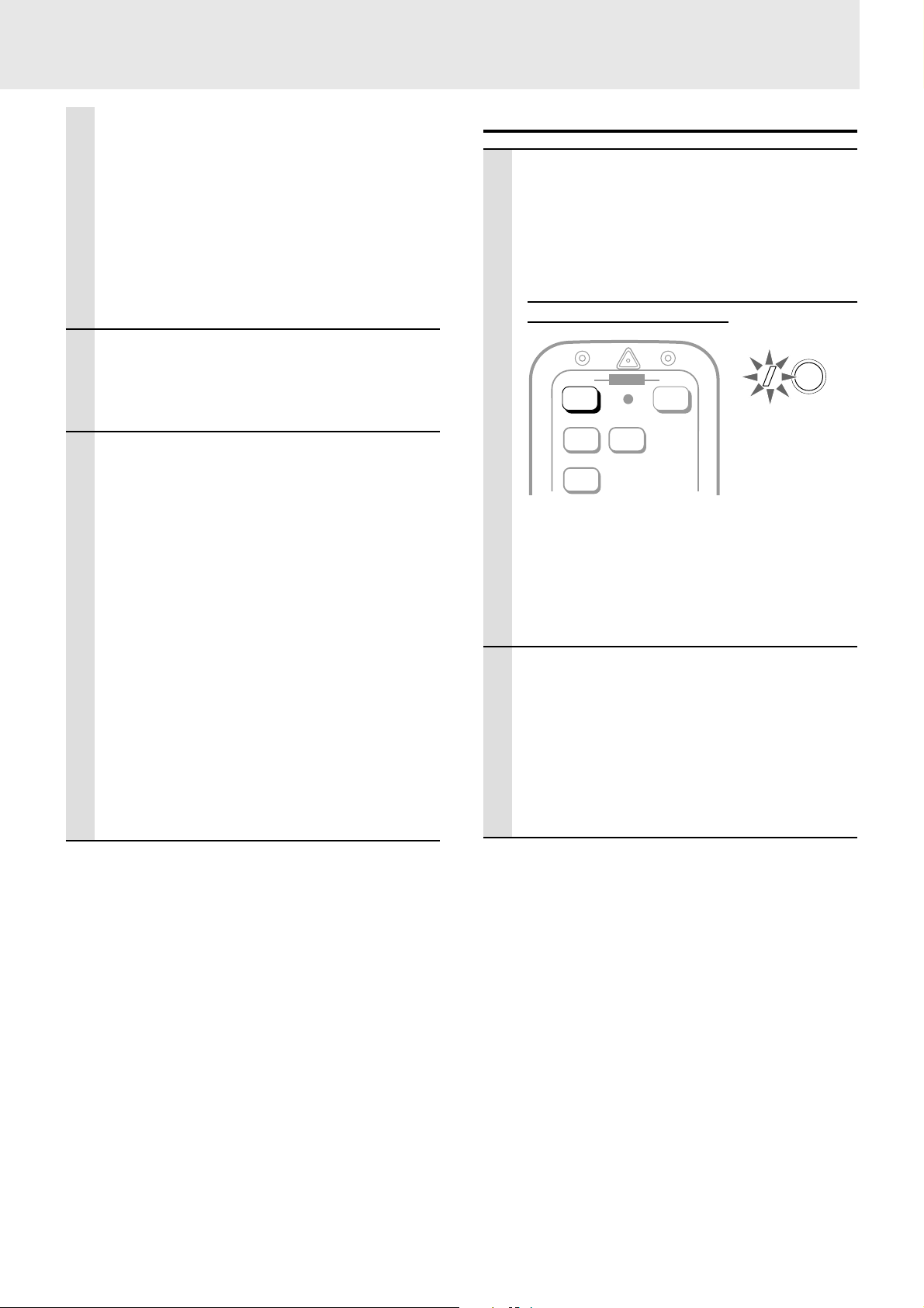
Using the laser pointer
Y ou can highlight the desired point on the scr een with a beam of red
light.
Caution
• Do not look into the laser pointer while it is on, nor point the laser
beam at any other persons. This could result in serious eye damage or
blindness.
• Use of controls or adjustments or performance other than those
specified herein may result in hazardous radiation exposure.
Turning off the image and muting the
sound temporarily
Press MUTE.
The image turns off and the sound is muted at the
same time. To restore the picture and sound,
press the button again.
MUTE
Freezing a moving picture
You can capture the desired frame of a moving picture.
Press FREEZE.
A still image of the current frame is displayed. To
restore the present picture, press the button
again.
FREEZE
Press LASER.
The red light is on while pressing the button.
The light goes out when you release the button.
LASER
Tip
The still picture can also be enlarged (see pages 20 and 21).
(Continued on next page.)
E – 19
Page 21

Various functions while using the unit(continued)
POWER
OFF ON
VIDEO
S-VIDEO
RGB
POINTER button
MAGNIFY button
MENU
–
POINTER MUTE FREEZE
MAGNIFY KEYSTONE V OLUM E
+
–
PLUS
R-CLICK
LASER
+
Cursor key
+–+
–
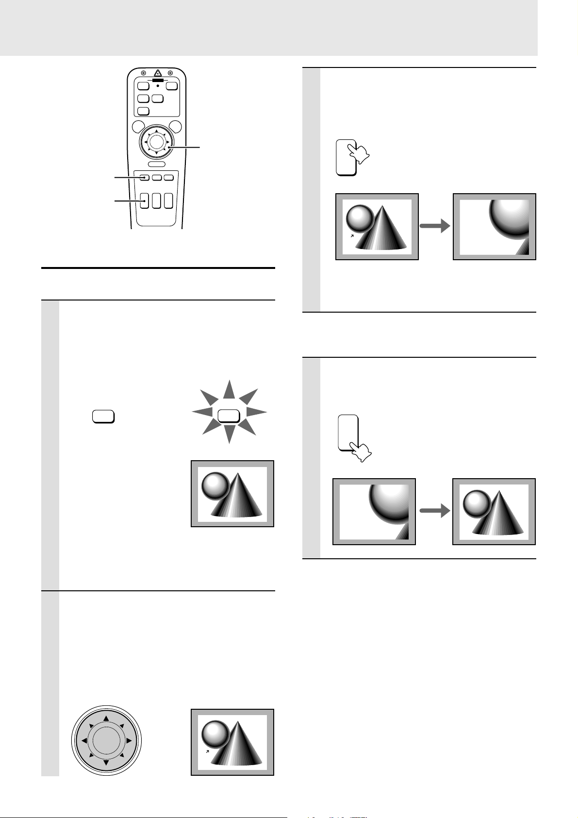
Enlarging the picture
You can enlarge the picture up to four times the original size.
Press MAGNIFY +.
While the button is pressed the picture is enlarged until it becomes four times the original
size.
Release the button at the desired size.
MAGNIFY
+
–
Original size
Four times as large
as the original size
To move to the desired portion of the enlarged
picture
1 Press POINTER.
The button lights in red. If you don’t proceed to
step 2 within ten seconds, the button goes off.
POINTER
POINTER
2 Press the desired portion of the cursor
key while POINTER is lit.
The available directions are indicated by the
eight triangle marks on the cursor key. The picture will move in the direction of the mark you are
pressing.
Move upward
Move leftward
–
Move rightward
+
Note
The quality of the enlarged picture deteriorates compared to
the original size picture.
To reduce the size of the enlarged picture
Press MAGNIFY –.
While the button is pressed the picture is reduced
until it becomes the original size.
MAGNIFY
+
–
Enlarged size
Original size
Move downward
Note
The original size of the picture cannot be moved because the
whole image is fully displayed.
E – 20
Page 22
OFF ON
VIDEO
RGB
MENU
–
POWER
S-VIDEO
LASER
+
Cursor key
3 Press MAGNIFY +.
While the button is pressed, the picture is
enlarged until it becomes four times the original
size.
MAGNIFY
+
R-CLICK
POINTER button
MAGNIFY button
POINTER MUTE FREEZE
MAGNIFY KEYSTONE V OLUM E
+
–
–
PLUS
+–+
Enlarging the picture after selecting the
portion you wish to enlarge
After selecting the portion you wish to enlarge, you can enlarge the
picture up to four times the original size.
1 While the picture is projected at its
original size, press POINTER.
The button lights in red, then the pointer is displayed on the screen.
If you don’t proceed to step 2 within ten seconds,
the button goes off.
POINTER
POINTER
Original size
–
Four times as large
Original size
as the original size
Note
The quality of the enlarged picture deteriorates compared to
the original size picture.
To reduce the size of the enlarged picture
Press MAGNIFY –.
While the button is pressed, the picture is
reduced until it becomes the original size.
MAGNIFY
+
–
Note
You can also display the pointer on the menu screen. See page
25.
You can select from among eight pointers using the menu. See
page 25.
2 Press the desired portion of the cursor
key to move the pointer while POINTER is
lit.
The available directions are indicated by the
eight triangle marks on the cursor key. The
pointer will move in the direction of the mark you
are pressing.
Original size
Enlarged size Original size
E – 21
Page 23
Menu operation
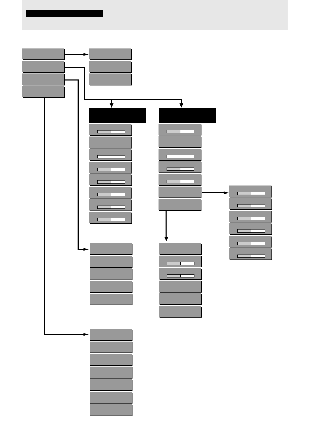
Menu structure
For operational instructions, refer to the page indicated in brackets.
SOURCE MENU
IMAGE ADJ MENU
POWER MENU
SETTING MENU
(23)
(24)
(29)
(24)
VIDEO
AUTO
S-VIDEO
AUTO
RGB
AUTO
(23)
(23)
(23)
When the input source
is VIDEO or S-VIDEO
VOLUME
– +
IMAGE MODE
NORMAL
KEYSTONE
– +
BRIGHTNESS
– +
CONTRAST
– +
COLOR
– +
TINT
– +
SHARPNESS
– +
LAMP USAGE
0HOURS
AUTO START
OFF
POWER OFF
OFF
KEYSTONE SAVE
OFF
DISPLAY
ON
(25)
(28)
(24)
(28)
(28)
(28)
(28)
(28)
(30)
(29)
(29)
(24)
(29)
Note
The menu will not be displayed if the picture is
enlarged even slightly. In such a case, reduce the
picture size to normal before starting the menu
operation.
When the input source
is RGB
VOLUME
– +
IMAGE MODE
NORMAL
KEYSTONE
– +
BRIGHTNESS
– +
CONTRAST
– +
WHITE BALANCE
AUTO MODE
ON
The menu below is
displayed when “AUTO
MODE” is set to “OFF.”
AUTO MODE
OFF
H POSITION
– +
V POSITION
– +
PICTURE ADJ
1160
FINE PICTURE
64
RESOLUTION
AUTO
(25)
(28)
(24)
(28)
(28)
(28)
(28)
(27)
(27)
(27)
(27)
(27)
(27)
BRIGHTNESS R
– +
BRIGHTNESS G
– +
BRIGHTNESS B
– +
CONTRAST R
– +
CONTRAST G
– +
CONTRAST B
– +
(28)
(28)
(28)
(28)
(28)
(28)
WHITE PICTURE
NORMAL
BACKGROUND
BLUEBACK
VIDEO STANDARD
AUTO
PROJECTION
FRONT / FLOOR
LANGUAGE
ENGLISH
POINTER
POINTER1
RESET
48KHz
(28)
(25)
(24)
(24)
(24)
(25)
(30)
E – 22
Page 24

Basic operation (Selecting the input source)
R-CLICK
OFF ONPOWER
VIDEO
S-VIDEO
MENU button
RGB
MENU
–
LASER
+
L-CLICK button
(On bottom of
the remote
control)
Cursor key
R-CLICK
POINTER MUTE FREEZE
MAGNIFY VOLUME
KEYSTONE
+
+
+
–
–
–
PLUS
R-CLICK button
1 Press MENU.
The button lights in red and the main menu
appears on the screen.
If you don’t proceed to step 2 within ten seconds,
the button goes off.
MENU
Note
The menu will not be displayed if the picture is enlarged even slightly. In
such a case, reduce the picture size to normal before
starting the menu operation.
MENU
SOURCE MENU
IMAGE ADJ MENU
POWER MENU
SETTING MENU
2 Press the cursor / key to select
“SOURCE MENU.”
–
+
SOURCE MENU
IMAGE ADJ MENU
POWER MENU
SETTING MENU
3 Press L-CLICK.
The source menu appears on the screen.
VIDEO
AUTO
S-VIDEO
AUTO
RGB
AUTO
4 Press the cursor / key to select the
desired input source.
VIDEO
AUTO
S-VIDEO
–
+
AUTO
RGB
AUTO
5 Press L-CLICK.
The source you’ve selected in step 4 is confirmed, then the picture from the selected source
is projected on the screen.
6 Press R-CLICK to turn off the menu dis-
play.
Whenever you wish to turn off the menu display,
press the R-CLICK button.
Operating using the unit
The menu operation is explained using the remote control, however, it can also be controlled using the unit operation buttons.
To operate using the unit, refer to the comparison table below.
STATUS
MENU
MENU button
SELECT
The remote control and unit button comparison table
Remote control buttons
MENU
The main menu appears on
the screen when you press
this button.
To turn off any menu, press
R-CLICK.
Cursor / key s
Press either key to select the
menu item.
Cursor + / – keys
Press either key to choose
the setting or value of the
selected menu item.
L-CLICK
Press this button whenever
confirmation is required.
POWER
ENTER
ENTER button
UP
DOWN
SELECT
UP/DOWN/+/–
buttons
Unit operation buttons
MENU
The main menu appears on the
screen when you press this
button.
To turn off any menu, press
R-CLICK on the remote
control.
(You cannot turn off the
menu with the unit’s button.)
SELECT UP/DOWN
Press either button to select
the menu item.
SELECT + / –
Press either button to choose
the setting or value of the selected menu item.
ENTER
Press this button whenever
confirmation is required.
E – 23
Page 25
Correcting the
Selecting a menu
keystoning effect
The keystone correction function can be used if the vertical offset
cannot be completely adjusted with the adjusters (see page 16).
The unit retains the correction value even if you select another input
source after keystoning unless you turn off the unit.
This correction can also be made with KEYSTONE +/– on the
remote control (see page 16).
1 Press MENU to display the main menu.
2 Press the cursor / keys to select “IMAGE ADJ
MENU.”
3 Press L-CLICK to display the IMAGE ADJ MENU.
4 Press the cursor / keys to select “KEYSTONE.”
5 Press the cursor +/– keys to correct the offset image.
For more information, see page 16.
Saving the corrected value
The keystoning value returns to the standard settings after the
power of the unit is turned off. To keep the corrected value for the
next use of the unit, set “KEYSTONE SAVE” to “ON.”
1 After keystoning, press MENU to display the main menu.
2 Press the cursor / keys to select “POWER MENU.”
3 Press L-CLICK to display the POWER MENU.
4 Press the cursor / keys to select “KEYSTONE SAVE. ”
5 Press the cursor + key to select “ON.”
language
1 Press MENU to display the main menu.
2 Press the cursor / keys to select “SETTING MENU.”
3 Press L-CLICK to display the SETTING MENU.
4 Press the cursor / keys to select “LANGUAGE,” then
press the cursor + / – keys to select one of the following
languages:
• ENGLISH (English),
• DEUTSCH (German),
• FRANÇAIS (French),
• ITALIANO (Italiano),
• ESPAÑOL (Spanish),
• SVENSKA (Swedish), or
• (Japanese).
5 Press L-CLICK.
Selecting a
projection type
This reorients your image for your type of projection.
1 Press MENU to display the main menu.
2 Press the cursor / keys to select “SETTING MENU.”
3 Press L-CLICK to display the SETTING MENU.
4 Press the cursor / keys to select “PROJECTION.”
5 Press the cursor + / – keys to select the projection type
which suits the unit setup conditions.
The following four projection types can be selected:
• FRONT FLOOR (Normal),
• REAR CEILING (Upside down and horizontally re-
versed),
• REAR FLOOR (Horizontally reversed), or
• FRONT CEILING (Upside down).
6 Press L-CLICK.
Selecting the
color system
The unit can be changed to the following color systems:
• NTSC 3.58
• PAL (except for the PAL-M and PAL-N systems)*
• SECAM
• NTSC 4.43
If your color system is NTSC 3.58 or PAL, select “AUTO” (factory
setting).
If your color system is SECAM or NTSC 4.43, select “SECAM” or
“4.43NTSC.”
1 Press MENU to display the main menu.
2 Press the cursor / keys to select “SETTING MENU.”
3 Press L-CLICK to display the SETTING MENU.
4 Press the cursor / keys to select “VIDEO STAN-
DARD.”
5 Press the cursor +/– keys to select the color system.
6 Press L-CLICK to change the unit to the selected color
system.
* The unit cannot project the PAL-M
and PAL-N systems.
E – 24
Page 26

Selecting the
Selecting the
pointer type
If you press POINTER on the remote control while the picture is
projected at its original size, the pointer is displayed on the screen
(see page 21).
You can select from among eight pointers.
1 Press MENU to display the main menu.
2 Press the cursor / keys to select “SETTING MENU.”
3 Press L-CLICK to display the SETTING MENU.
4 Press the cursor / keys to select “POINTER.”
5 Press the cursor +/– keys to select one of the following
eight pointer types.
6 Press L-CLICK to confirm the pointer type.
background
1 Press MENU to display the main menu.
2 Press the cursor / key to select “SETTING MENU.”
3 Press L-CLICK to display the SETTING MENU.
4 Press the cursor / key to select “BACKGROUND.”
5 Press the cursor + / – key to select one of the following
background types:
• BLUEBACK or
• BLACKBACK.
6 Press L-CLICK.
Adjusting the
volume
The last adjusted volume will not be changed if you change the
input source from S-VIDEO to VIDEO, and vice versa. But the
volume for RGB is independently set.
The volume can also be adjusted with VOLUME +/– on the remote
control (see page 19).
1 Press MENU to display the main menu.
2 Press the cursor / keys to select “IMAGE ADJ
MENU.”
3 Press L-CLICK to display the IMAGE ADJ MENU.
4 Press the cursor / keys to select “VOLUME,” then
press the cursor + / – keys to adjust the volume.
E – 25
Page 27

Adjusting the projected image from
the computer
The unit selects the most suitable resolutions as shown in the “Timing Chart” below according to the incoming signals from the RGB IN
connector when “AUTO MODE” is set to “ON.” (See page 27). Howe ver , you may need manual adjustment depending on the computer. If you
have any vertical banding, noise, dot interference , or crosstalk on the projected picture, adjust the clock frequency with “PICTURE ADJ” then
the clock phase with “FINE PICTURE” (see page 27). You can also adjust the horizontal and vertical position of the image (see page 27).
When adjusting manually (when “AUTO MODE” is set to “OFF”), you can choose to project the image at the original size of the incoming
signal resolution (see page 27). (Normally, the image is enlarged or reduced to the most suitable size automatically.)
Timing Chart
Resolution H Sync. (kHz) V Sync. (Hz)
IBM PC/AT compatible machine 640 × 350 31.5 70.1
640 × 350 37.9 85.1
720 × 350 31.5 70.0
640 × 400 31.5 70.1
640 × 400 37.9 85.1
720 × 400 31.5 70.0
720 × 400 37.9 85.0
640 × 480 31.5 60.0
640 × 480 37.9 72.8
640 × 480 37.5 75.0
640 × 480 43.3 85.0
800 × 600 35.2 56.3
800 × 600 37.9 60.3
800 × 600 46.9 75.0
800 × 600 48.1 72.2
800 × 600 53.7 85.1
1024 × 768 48.4 60.0
1024 × 768 56.5 70.1
1024 × 768 58.1 72.0
1024 × 768 60.0 75.0
1024 × 768 68.7 85.0
1280 × 1024 64.0 60.0
1280 × 1024 80.0 75.0
Apple Macintosh 640 × 480 35.0 66.7
832 × 624 49.7 74.5
1024 × 768 60.2 74.9
1152 × 870 68.7 75.6
1280 × 1024 81.1 76.1
Sun 1152 × 900 61.8 66.0
1280 × 1024 74.9 69.9
1280 × 1024 81.1 76.1
SGI 1024 × 768 49.7 60.4
1280 × 1024 63.9 60.0
1152 × 900 71.7 76.1
HP 1280 × 1024 78.1 72.0
Note on AccuBlend
(U2-1130/U2-1110)
The resolution of the unit is 1024 × 768. Other resolution images (e.g. 1280 × 1024) are compressed into 1024 × 768 (AccuBlend). In such a case,
projected letters and lines might appear unevenly.
(U2-811)
The resolution of the unit is 800 × 600. Other resolution images (e.g. 1024 × 768) are compressed into 800 × 600 (AccuBlend). In such a case,
projected letters and lines might appear unevenly.
TM
E – 26
Page 28
Adjusting the clock frequency (PICTURE
ADJ) and clock phase (FINE PICTURE)
manually
Adjusting the horizontal (H POSITION) and
vertical (V POSITION) position of the
image
When “AUTO MODE” is set to “ON,” the clock frequency and
clock phase will be adjusted automatically. However, if you need
any manual adjustment for these two items, you first need to set
“AUTO MODE” to “OFF” as indicated in the following steps.
Adjust the clock frequency to eliminate any vertical banding, then
the clock phase to reduce any video noise, dot interference, or cross
talk. (When the clock phase is not matched evenly, the image
appears to be shimmering.)
1 Setting the input source to “RGB”
Select the RGB input source (see page 15 or 23).
2 Setting “AUTO MODE” to “OFF” for manual ad-
justment
1 Press MENU to display the main menu.
2 Press the cursor / keys to select “IMAGE ADJ
MENU.”
3 Press L-CLICK to display the IMAGE ADJ MENU.
4 Press the cursor / keys to select “AUTO MODE.”
5 Press the cursor – key to select “OFF,” then press L-
CLICK.
The AUTO MODE OFF menu appears.
3 Adjusting the clock frequency
1 Press the cursor / keys to select “PICTURE ADJ. ”
2 Press the cursor – key until the vertical banding disa p-
pears.
Press + to increase the frequency and – to decrease.
4 Adjusting the clock phase
1 Press the cursor / keys to select “FINE PICTURE.”
2 Press the cursor +/– keys until the video noise, dot
interference, and cross talk are reduced.
Press + to increase the phase and – to decrease the
phase.
1 Carry out steps 1 and 2 in the left column.
2 Press the cursor / keys to select “H POSITION.”
3 Press the cursor +/– keys to adjust the horizontal position.
Press + key to move the image right and – key to move it
left.
4 Press the cursor / keys to select “V POSITION.”
5 Press the cursor +/– keys to adjust the vertical position.
Press + keys to move the image up and – key to move it
down.
Adjusting the image size automatically/
Displaying the image at its original size
Normally the unit enlarges or reduces the image from the computer
to the most suitable size, however, you can choose to project the
image at the original size of the incoming signal resolution.
1 Carry out steps 1 and 2 in the left column.
2 Press the cursor / keys to select “RESOLUTION.”
3 Press the cursor +/– keys to select “AUTO” or “REAL
MODE.”
When adjusting the size of the image automatically, se-
lect “AUTO.”
When displaying the image at its original size, select
“REAL MODE.”
4 Press L-CLICK to confirm the setting in step 3.
If the image (and the menu) disappears while setting
the clock frequency or clock phase
Carry out the following steps.
1 Turn off the source connected to the RGB IN connector.
The incoming signals from the source go down and a blue or black
screen will be displayed. (The background type differs depending on
the “BACKGROUND” setting. See page 25.)
2 Carry out “Resetting to the factory settings” on page 30.
3 Turn on the source, then carry out “Adjusting the clock fr equency and
clock phase manually” from the beginning.
When you have connected another computer
Set “AUTO MODE” to “ON” by pressing the cursor + key in step 2-5
above.
E – 27
Page 29
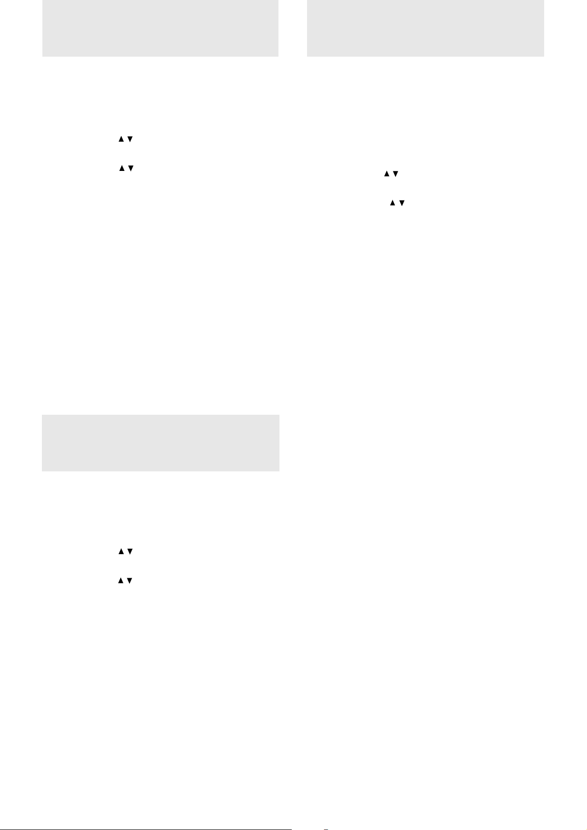
Adjusting the
Selecting the
picture elements
The picture elements such as brightness, contrast, white balance,
and so on can be adjusted individually for each input source. The
adjustable items vary depending on the input source.
(The elements
marked with “
are adjustable.)
BRIGHTNESS
CONTRAST
COLOR –
TINT –
SHARPNESS –
WHITE BALANCE –
”
VIDEO/S-VIDEO RGB
1 Select the input source (see page 15 or 23).
2 Press MENU to display the main menu.
3 Press the cursor / keys to select “IMAGE ADJ
MENU.”
4 Press L-CLICK to display the IMAGE ADJ MENU.
5 Press the cursor / keys to select “BRIGHTNESS,” then
press the cursor +/– keys to adjust the brightness.
6 Press the cursor / keys to select “CONTRAST,” then
press the cursor +/– keys to adjust the contrast.
When the input source
is VIDEO or S-VIDEO
7 Press the cursor / keys
to select “COLOR,” then
press the cursor +/– keys
to adjust the color.
8 Press the cursor / keys
to select “TINT,” then
press the cursor +/– keys
to adjust the tint.
Note
The tint control doesn’t oper-
ate with a PAL or SECAM
source.
9 Press the cursor / keys
to select “SHARPNESS,”
then press the cursor +/–
keys to adjust the sharp-
ness.
Input source
When the input source
is RGB
7 Press the cursor / keys
to select “WHITE BALANCE,” then press L-
CLICK.
The WHITE BALANCE
menu appears.
8 Press the cursor / keys
to select each item in the
WHITE BALANCE
menu, then press the cursor +/– keys to adjust the
item for the white color
balance.
picture type
Selecting the brightness or color oriented image
setting
The brightness oriented setting may be suitable for PC images and
the color oriented setting may be suitable for movie pictures. In this
way, you can focus on either brightness or color.
This setting is applied to all input sources regardless of the present
input source.
1 Press MENU to display the main menu.
2 Press the cursor / keys to select “SETTING MENU.”
3 Press L-CLICK to display the SETTING MENU.
4 Press the cursor / keys to select “WHITE PICTURE,”
then press the cursor +/– keys to select the white picture
mode.
The following two types can be selected:
• NORMAL to set the unit to the brightness oriented
setting or
• QUIET to reduce brightness for better color expression,
5 Press L-CLICK to confirm the setting.
Selecting the color preference
After selecting the brightness or color oriented image setting, you
can set the color preference individually for each input source
according to the video content and your preferences.
1 Select the input source (see page 15 or 23).
2 Press MENU to display the main menu.
3 Press the cursor / keys to select “IMAGE ADJ
MENU.”
4 Press L-CLICK to display the IMAGE ADJ MENU.
5 Press the cursor / keys to select “IMAGE MODE,”
then press the cursor +/– keys to select the gamma mode.
The following three types of gamma modes can be se-
lected according to your preferences:
• NORMAL,
• NATURAL 1, or
• NATURAL 2.
E – 28
Page 30
Activating the power
Activating the on–
saving function
This function operates only with an RGB input source.
If there are no input signals from the RGB IN connector for more
than five minutes, the unit will automatically turn of f and enter the
standby mode.
1 Press MENU to display the main menu.
2 Press the cursor
3 Press L-CLICK to display the POWER MENU.
4 Press the cursor
press the cursor + key to select “ON” to activate the
power saving function.
To deactivate the function, set “POWER OFF” to “OFF”
by pressing the cursor – key.
/ keys to select “POWER MENU.”
/ keys to select “POWER OFF,” then
screen function
The factory setting of this function is “ON.”
When the function is activated, the source menu appears on the
screen in the following cases:
• The source menu appears for three seconds when you select the
input source with the remote control, and
• The source menu appears for approximately twenty seconds
when you turn on the unit.
1 Press MENU to display the main menu.
2 Press the cursor / keys to select “SETTING MENU.”
3 Press L-CLICK to display the SETTING MENU.
4 Press the cursor / keys to select “DISPLAY,” then
press the cursor + key to select “ON” to activate the on-
screen function.
To deactivate the function, set “DISPLAY” to “OFF” by
pressing the cursor – key.
Quick-starting
the unit
The unit can be turned on by only connecting the power cable (see
page 15) if you set “AUTO START” to “ON.” There is no need to
press POWER ON on the remote control or POWER on the unit
after “AUTO START” is activated to turn on the unit.
1 Press MENU to display the main menu.
2 Press the cursor / keys to select “POWER MENU.”
3 Press L-CLICK to display the POWER MENU.
4 Press the cursor / keys to select “AUTO START,” then
press the cursor + key to select “ON” to activate the
function.
T o deactivate the function, set “AUT O START” to “OFF”
by pressing the cursor – key.
E – 29
Page 31

Checking hours
of lamp usage
Resetting to the
factory settings
The lamp cartridge must be replaced after 1000 hours of usage.
When 1000 hours have elapsed the STATUS indicator will light in
red (see page 32). Periodically check the hours of lamp usage in the
menu so that you will have time to purchase a new lamp cartridge
before the old one burns out.
1 Press MENU to display the main menu.
2 Press the cursor / keys to select “POWER MENU.”
3 Press L-CLICK to display the POWER MENU.
4 Press the cursor / keys to select “LAMP USAGE.”
The lamp usage hours will be displayed.
Resetting the lamp usage hours to zero
You need to reset the lamp usage hours to zero after replacing the
lamp cartridge (see page 33).
1 Carry out the steps above.
2 Press POWER ON on the remote control for more than
ten seconds.
“LAMP USAGE” will be reset to zero and the STATUS
indicator will go off (see page 32).
If the unit doesn’t turn on because lamp
usage exceeds 1100 hours.
The unit is designed not to turn on after the lamp usage has
exceeded 1100 hours. (If the unit is in use, it will go off.) If this
happens you must replace the lamp cartridge with a new one
immediately. After replacing the lamp cartridge, you need to reset
the lamp usage hours to zero to enable you to turn on the unit.
The following items can be reset to the standard settings.
• H POSITION
• V POSITION
• PICTURE ADJ
• FINE PICTURE
• BRIGHTNESS
• CONTRAST
• COLOR
• TINT
• SHARPNESS
• WHITE BALANCE
Although the above items for the particular input source are stored
in memory when setting the value, the items for all input sources
will be reset regardless of the input source when resetting.
1 Press MENU to display the main menu.
2 Press the cursor / keys to select “SETTING MENU.”
3 Press L-CLICK to display the SETTING MENU.
4 Press the cursor / keys to select “RESET.”
The horizontal frequency appears under “RESET” when
the present input source is RGB.
5 Press the cursor + key for more than three seconds.
“COMPLETED” appears under the title “RESET” after
the reset is complete.
1 Connect the power cable (see step 1 on page 15).
2 Press POWER OFF on the remote control for more ten
seconds.
“LAMP USAGE” will be reset to zero and the STATUS
indicator will go off (see page 32).
E – 30
Page 32

Others
Troubleshooting
This section helps you resolve problems you may encounter while setting up or using the unit.
Common Problems & Solutions
Problem
Does not turn on
No picture
Image isn’t square on the screen
Picture is blurred
Remedy
• Check that the power cable is properly connected to the unit and wall outlet (the
mains). (See page 15).
• Check the STATUS indicator to see if the unit has overheated or the lamp usage
has exceeded 1100 hours. (See page 32.)
• Check that you have selected the proper input source you wish to project. (See
pages 15 and 32.)
• Ensure all the cables are connected properly. (See pages 11 to 13.)
• Adjust the brightness and contrast. (See page 28.)
• Remove the lens cap. (See page 15.)
• Is the POWER indicator flashing? (See page 15.)
• Is the STATUS indicator flashing? (See page 32.)
• Reposition the unit to improve its angle on the screen. (See pages 15 and 16.)
• Is the vertical offset properly corrected using the keystone function? (See page
16).
• Adjust the focus. (See page 16.)
• Reposition the unit to improve its angle to the screen. (See pages 15 and 16.)
• Ensure that the distance between the unit and screen is within the adjustment
range of the lens. (See pages 9 and 10.)
Remote control does not work
The STATUS indicator is lit or
flashing
Cross color appears in RGB mode
• Replace the dead batteries with new ones. (See page 5).
• Make sure there is no obstacle between the remote control and the unit.
• Stand within 4m (13 feet) of the unit. (See page 5.)
See the STATUS indicator message chart on the next page.
• If “AUTO MODE” is set to “ON,” set it to “OFF” then manually adjust the
clock frequency and clock phase. (See page 27.)
• If “AUTO MODE” is set to “OFF,” set it to “ON.” (See page 27.)
E – 31
Page 33

When the STATUS indicator lights or flashes
STATUS indicator
Status Light Messages
Condition
OFF
On Continually
Flashing Very Rapidly (On and off
in a cycle of 1 sec.)
STATUS
MENU
SELECT
POWER
ENTER
UP
DOWN
Status
Normal
The lamp usage has exceeded 1000 hours of operation and should be replaced.
• The lamp cover is not correctly attached. Replace it correctly.
Flashing Rapidly
(On and off in a cycle of 4 sec.)
Flashing Slowly (On and off in a
cycle of 8 sec.)
Flashing Very Slowly (On and off in
a cycle of 12 sec.)
• The temperature protector has been triggered. If the room temperature is high,
move the unit to a cool location. If the temperature within the unit is high, c hec k the
cooling fan ventilation slots and the ventilation slots on the bottom of the unit. If
any of the slots are blocked, remove whatever is blocking them.
• The temperatur e protector has been triggered. If you try to turn on the unit immediately after turning off, sometimes the power does not come on. If this happens, wait
at least one minute, then turn on the unit again.
• The lamp lighting voltage error detection protector has been triggered. Wait at
least one minute before turning on the unit again. If this does not solve the problem,
please contact your dealer.
The cooling fan has stopped. Contact your PLUS dealer for service.
The lamp is not turned on.
• The unit was turned on immediately after being turned off. Turn off the unit, wait at
least one minute, then turn on the unit again.
• The lamp is dead. Replace the lamp cartridge. (See page 33.)
E – 32
Page 34

Replacing the lamp cartridge
The lamp life is about 1,000 hours (under the test conditions of our
company), howev er , it may become shorter depending on the conditions of
usage.
After the lamp has been operating for 1000 hours or longer, the STATUS
indicator on the control panel will light and the “LAMP USAGE” icon
which shows hours of total lamp usage will be displayed on the screen.
When this happens, turn off the unit and replace the lamp cartridge with a
new one. The unit will not turn on after 1100 hours. (It will go of f if it is in
use.)
CAUTION
• DO NOT TOUCH THE LAMP immediately after it has been
used. It will be extremely hot. Allow at least one hour for the
lamp to cool before handling.
• DO NOT LOOSEN ANY SCREWS except for those mentioned in the instructions below. There is danger of electric
shock.
Lamp cartridge replacement procedure
1 Disconnect the power cable.
Wait at least one hour for the lamp to cool.
2 Turn the unit upside down carefully.
3 Loosen the lamp cover securing screw.
4 Remove the lamp cover.
Step 3
Step 4
Step 5
Step 6
Lamp Cover
Lamp cartridge
CAUTION: Do not use a lamp cartridge other than the PLUS
replacement lamp cartridge. Order this from your PLUS dealer
using the unit model number (see “Notes” below).
5 Loosen the three lamp cartridge securing screws.
(This unit has a safety switch.)
6 Hold the handle then pull the lamp car tridge upward to remove
it.
7 Install the new lamp cartridge.
8 Secure the lamp cartridge with the three screws.
9 Replace the lamp cover and secure it with the securing screw.
10 Return the unit to the normal position, connect the po wer cable,
and turn on the unit.
11 Reset “LAMP USAGE.” (See page 30).
Notes
• When the lamp usage time reaches 1100 hours, it becomes impossible
to switch on the power and menus are not displayed. In such a case,
see “If the unit doesn’t go on because lamp usage exceeds 1100
hours” on page 30.
• Obtain a replacement lamp cartridge at the store where the unit was
purchased. Please specify the following information when ordering a
replacement lamp cartridge:
– Model name : U2-150
– Product code : 28-640
Step 7
Step 8
Step 9
E – 33
Page 35

Specifications
Optical
TM
DMD
Lens Manual zoom, manual focus
Lamp High Performance Compact Lamp 150 W
Image Size 635 to 7620 mm (25 to 300 in.) diagonal
Projection Distance 1.2 to 12.3m (3.9 to 40.4 ft.)
Light Output (U2-1130) (U2-1110/U2-811)
Contrast Ratio 800 : 1
Electrical
Inputs Video (NTSC / PAL / SECAM / NTSC4.43)
Single Chip Digital Micro Device (DMDTM)
(U2-1130/U2-1110) (U2-811)
1024×768 dots 800×600 dots
(U2-1130) (U2-1110/U2-811)
F=2.7 to 3.0 f=35 to 42 mm F=3.0 to 3.3 f=27.5 to 33 mm
(1.4 to 1.65 in.) (1.1 to 1.3 in.)
1300 ANSI lumens 1100 ANSI lumens
(normally white) (normally white)
RGB (H:15 to 85 kHz, V: 50 to 85 Hz)
Video Bandwidth 60 MHz
Color Reproduction Full color, 16.7 million colors simultaneously.
Horizontal Resolution NTSC 500, PAL 500, SECAM 300, NTSC4.43 350 TV lines
Resolution (U2-1130/U2-1110)
SXGA (Compression), XGA (True), SVGA/VGA (Expansion/True)
(U2-811)
XGA (Compression), SVGA (True), VGA (Expansion/True)
Power Requirement 100 to 120/220 to 240 V AC, 50/60 Hz
Input Current 2.2A/1.0A (220W)
Mechanical
Dimensions 23.5 cm (W) × 5.8 cm (H) × 29.7 cm (D) / 9.3 in.(W) × 2.3 in.(H) × 11.7 in.(D)
Net W eight (U2-1130) (U2-1110/U2-811)
2.6 kg / 5.7 lbs 2.5 kg / 5.5 lbs
Operational Temperatures Data projector: 5° to 35°C (41° to 95°F), 30 to 85% humidity
Remote control: 0° to 60°C (32° to 140°F)
Regulations UL Approved (UL 1950, CSA 950)
Meets DOC Canada requirements
Meets FCC Class A requirements
Meets EMC Directive (EN55022, EN61000-3-2, EN61000-3-3, EN50082-1)
Meets Low Voltage Directive (EN60950, TÜV GS Approved)
E – 34
Page 36

D-Sub Pin Assignments
PC 15-Pin mini D-Sub
Pin No.
1
2
3
4
5
6
7
8
9
10
11
12
13
14
15
Signal to be connected
Red
Green
Blue
GND
GND
Red GND
Green GND
Blue GND
No Connection
Digital GND
GND
SDA
Horizontal Sync
Vertical Sync
SCL
E – 35
(Continued on next page.)
Page 37

Specifications (continued)
Dimensions
(U2-1130)
DOWN
UP
SELECT
MENU
ENTER
297mm/11.7″
PC AUDIORGB INMOUSE AUDIOS-VIDEO VIDEO
STATUS
POWER
L/MONO R
18.6mm/0.7″
23.6mm/0.9″
76.9mm/3.0″
58mm/
13mm/0.5″
2.3″
64mm/2.5″
235mm/9.3″
50.4mm/2.0″
(U2-1110/U2-811)
SELECT
MENU
DOWN
UP
ENTER
STATUS
POWER
297mm/11.7″
37. 4mm/1.5″
235mm/9.3″
1.8mm/0.1″
58mm/2.3″
64mm/2.5″
13mm/0.5″
PC AUDIORGB INMOUSE AUDIOS-VIDEO VIDEO
L/MONO R
47.5mm/1.9″
34.5mm/1.4″
E – 36
Page 38

U2-1130/U2-1110/U2-811
Français
Page 39

INFORMATIONS IMPORTANTES
RELATIVES À LA SÉCURITÉ
Précautions
Lisez attentivement ce manuel av ant d’utiliser l’appareil de données PLUS U2-1130/U2-1110/U2-811, et conserv ez-le à portée de main pour
pouvoir vous y reporter ultérieurement.
Le numéro de série se trouve près de l’interrupteur d’alimentation principal, sur le panneau arrière de l’appareil.
Inscrivez-le ici :
ATTENTION
POUR ÉVITER TOUT RISQUE DE CHOC ÉLECTRIQUE, NE PAS OUVRIR LE COFFRET. L’APPAREIL NE
RENFERME AUCUNE PIÈCE QUI SOIT RÉPARABLE PAR L’UTILISATEUR. CONFIER TOUTE
RÉPARATION À UN PERSONNEL QUALIFIÉ DE LA SOCIÉTÉ PLUS.
AVERTISSEMENT
POUR ÉVITER TOUT RISQUE DE FEU OU DE
CHOC ÉLECTRIQUE, NE PAS EXPOSER
L’APPAREIL À LA PLUIE NI À L’HUMIDITÉ. NE
Avertissement
Cet appareil est un produit de classe A. Dans un
environnement domestique, il risque de provoquer un
brouillage radio, auquel cas l’utilisateur devra peut-être
prendre les mesures qui s’imposent.
PAS UTILISER LA FICHE AVEC MISE À LA
TERRE DE L’APPAREIL AVEC UNE
RALLONGE OU UNE PRISE SECTEUR SI LES
TROIS BROCHES NE PEUVENT PAS ÊTRE
TOUTES INSÉRÉES À FOND. NE PAS OUVRIR
LE COFFRET, CAR IL RENFERME DES
COMPOSANTS SOUS HAUTE TENSION.
CONFIER TOUTE RÉPARATION À UN PERSONNEL QUALIFIÉ DE LA SOCIÉTÉ PLUS.
Avis de conformité DOC
Cet appareil numérique de la classe A est conforme à la norme
NMB-003 du Canada.
Consignes de sécurité importantes
Ces consignes de sécurité ont pour but de garantir une longue durée de service de l’appareil et d’éviter le feu et les chocs électriques. Veuillez
les lire attentivement et observer tous les avertissements.
Installation
• Pour obtenir les meilleurs résultats, utilisez l’appareil dans une
pièce sombre.
• Placez l’appareil sur une surface plane et de niveau, dans un
endroit sec et loin de toute poussière et humidité.
• N’installez pas l’appareil en plein soleil, près d’un appareil de
chauffage ou d’un appareil dégageant de la chaleur.
• Toute exposition aux rayons du soleil, à la fumée ou à la vapeur
risque d’endommager les composants internes.
• Manipulez l’appareil avec précaution. Une chute ou un choc
risquent d’endommager les composants internes.
• Ne posez pas d’objets lourds sur l’appareil.
• Si vous installez l’appareil au plafond :
– Le plafond devra être suffisamment solide pour pouvoir sup-
porter le poids de l’appareil, et l’installation devra être
effectuée conformément aux codes de construction locaux.
– L’installation de l’appareil devra être confiée à un technicien
PLUS qualifié.
Alimentation
• L ’appareil est conçu pour fonctionner sur un courant alternatif de
100 à 120 ou de 220 à 240 V, 50/60 Hz. Vérifiez que
l’alimentation respecte ces exigences avant d’utiliser l’appareil.
• Pour les APPAREILS ENFICHABLES, la prise secteur devra se
trouver à proximité de l’appareil et être facilement accessible.
• Manipulez le câble d’alimentation avec précaution et évitez de
trop le plier. Un câble endommagé risque de pro voquer un feu ou
un choc électrique.
• Débranchez le câble d’alimentation (secteur) de la prise secteur
après l’utilisation.
Avant de débrancher le cordon d’alimentation, vérifiez que le
témoin POWER est allumé en orange (et non en vert).
F– 2
Page 40

Table des matiè res
Nettoyage
• Débranchez le câble d’alimentation (secteur) de l’appareil.
• Nettoyez périodiquement le coffret de l’appareil avec un chif fon
humide. S’il est très sale, utilisez un détergent doux. N’utilisez
jamais de détergents puissants ni de solvants comme de l’alcool
ou du diluant.
• Nettoyez l’objectif avec une poire soufflante ou un papier pour
nettoyage d’objectif, et veillez à ne pas rayer ni abîmer l’objectif.
• Nettoyez périodiquement les ouïes de ventilation et la section du
haut-parleur avec un aspirateur. Si la poussière accumulée
bouche les ouïes de ventilation, il se produira une surchauffe et
l’appareil risque de ne pas fonctionner correctement.
Lorsque vous utilisez un aspirateur, utilisez la brosse souple
accessoire. N’utilisez pas d’accessoire dur, par exemple un
suceur, pour ne pas endommager l’appareil.
Remplacement de la lampe
• Remplacez la lampe quand le voyant d’état s’allume. Si vous
continuez à utiliser la lampe après 1000 heures d’utilisation, la
lampe ne fonctionnera plus.
Précautions relatives au feu et aux chocs
électriques
• Pour éviter toute accumulation de chaleur à l’intérieur de
l’appareil, vérifiez qu’il y a une ventilation suffisante et que les
évents ne sont pas obstrués. Laissez un espace d’au moins 10 cm
entre l’appareil et les murs.
• Veillez à ce qu’aucun corps étranger, par ex emple des trombones
ou des morceaux de papier, ne pénètre à l’intérieur de l’appareil.
Ne tentez pas de retirer vous-même ces objets de l’appareil.
N’insérez pas d’objets métalliques, par exemple un fil électrique
ou un tournevis, dans l’appareil. Si un objet tombe dans
l’appareil, débranchez immédiatement le cordon d’alimentation
de l’appareil et faites enlever l’objet par un technicien PLUS
qualifié.
• Ne posez pas de liquides sur l’appareil.
• Ne regardez pas dans l’objectif lorsque l’appareil est allumé.
Cela pourrait gravement vous abîmer les yeux.
Transport
Pour transporter l’appareil, utilisez la mallette de transport qui est
livrée avec, et pour protéger l’objectif contre les rayures,
recouvrez-le toujours du capuchon d’objectif. Par ailleurs, ne
soumettez pas l’appareil proprement dit à un choc mécanique
puissant.
Etiquettes de précaution au dos de la
télécommande
INFORMATIONS IMPORTANTES RELATIVES À LA
SÉCURITÉ.................................................................................... 2
Table des matières ......................................................................... 3
Notions de base et préparation .............. 4
Caractéristiques ............................................................................. 4
Contrôle des accessoires fournis ................................................. 4
Préparation de la télécommande................................................... 5
Pièces principales et commandes ................................................. 6
Installation..................................................................................... 9
Branchements ......................................... 11
Raccordement d’une source vidéo.............................................. 11
Raccordement d’un PC ou d’un Macintosh ............................... 12
Utilisation de la télécommande comme souris
– Fonction Souris sans fil ........................................................... 14
Utilisation .................................................. 15
Utilisation de l’appareil .............................................................. 15
Fonctions spéciales disponibles lors de l’utilisation
de l’appareil................................................................................. 19
Utilisation des menu ................................ 22
Arborescence des menus............................................................. 22
Réglage de base (Sélection de la source) ................................... 23
Correction de la distorsion en trapèze ........................................ 24
Sélection du type de projection .................................................. 24
Sélection de la langue des menus ............................................... 24
Sélection du système de couleur................................................. 24
Sélection du type de pointeur ..................................................... 25
Réglage du volume sonore.......................................................... 25
Sélection du fond d’écran ........................................................... 25
Réglage de l’image projetée depuis l’ordinateur ....................... 26
Réglage des attributs de l’image................................................. 28
Sélection du type d’image .......................................................... 28
Activation de la fonction d’économie d’énergie ........................ 29
Allumage rapide de l’appareil .................................................... 29
Activation de la fonction messages d’écran ............................... 29
Contrôle du nombre d’heures d’utilisation de la lampe............. 30
Reprise des réglages d’usine....................................................... 30
AVOID EXPOSURE
-LASER
RADIATION IS EMITTED
FROM THIS APERTURE
CAUTION
LASER RADIATION-
DO NOT STARE INTO BEAM
WAVE LENGTH:650nm
MAX OUTPUT:1mW
CLASS II LASER PRODUCT
NO MIRE AL RAYO
LASER-STRAHLUNG U2-870R
NICHT IN DEN STRAHL
BLICKEN! LASER KLASSE 2
RAYCNNEMENT LASER NE PAS
REGARDER DANS LE FAISCEAU
APPAREIL A LASER DE CLASSSE 2
EN60825-1:1994+A11:1996
REMOTERADIACION LASER
CONTROL
MODEL:PRODUCTO LASER CLASSE 2
PLUS
CORPORATION
Divers ........................................................ 31
Dépannage ................................................................................... 31
Allumage ou clignotement du témoin STATUS......................... 32
Remplacement de la cartouche de lampe ................................... 33
Fiche technique ........................................................................... 34
F – 3
Page 41

Notions de base et pré paration
Caracté ristiques
Contrô le des
accessoires fournis
Nous vous félicitons d’avoir acheté l’appareil de
données U2-1130/U2-1110/U2-811.
Le U2-1130/U2-1110/U2-811 est l’un des projecteurs de données
les plus spectaculaires actuellement disponible sur le marché.
L’appareil vous permet de projeter des images bien nettes pouvant
atteindre plus de 7,6 mètres de diagonale à partir de votre ordinateur
PC ou Macintosh (modèle de bureau ou portable), de votre
magnétoscope, d’une caméra vidéo, d’un lecteur de disques laser,
d’un lecteur de DVD, etc.
L’appareil de données peut être placé sur une table, sur une table
roulante ou fixé de façon permanente au plafond*. Il peut aussi
servir à projeter des images de derrière l’écran.
*L’installation de l’appareil au plafond sera confiée exclusivement à un
technicien PLUS qualifié. Pour les détails, consultez votre revendeur.
Autres caractéristiques principales que vous
apprécierez
• Compatible avec les systèmes de TV couleur suivants:
– NTSC (standard américain et canadien)
– PAL (standard d’Europe de l’ouest)
– SECAM (standard français et d’Europe de l’est)
– NTSC4.43 (standard du Moyen-Orient)
• (U2-1130)
Extraordinaire luminosité de 1300 lumens ANSI, format
d’une feuille de papier/lettre de A4, et poids ne dépassant pas
2,6 kg.
(U2-1110/U2-811)
Extraordinaire luminosité de 1100 lumens ANSI, format
d’une feuille de papier/lettre de A4, et poids ne dépassant pas
2,5 kg.
Grâce au DMD (dispositif à miroir numérique) et au design
optique conçus par nous-mêmes, nous avons mis au point un effet
géométrique permettant d’accroître le rendement de l’éclairage.
Ce rendement accru de la lumière vous permet de reproduire les
3 couleurs de base (RGB) nécessaires pour la reproduction
couleur sur un seul DMD. Cela se traduit par une luminosité
accrue, un format plus petit et un poids plus faible.
• Images nettes et claires
Il n’y a aucune séparation des couleurs RGB, et les espaces entre
les pixels individuels ne ressortent pas. Il s’ensuit une restitution
claire et nette des petits caractères et des chiffres. Approchezvous, et vous remarquerez la différence de qualité !
• Images de qualité 3D extraordinairement nettes et claires,
avec des couleurs éclatantes, lors de la reproduction de DVD
et autres sources vidéo/information à haute qualité d’image
La reproduction fidèle des niveaux de gris permet d’offrir des
images plus naturelles. Les DVD et autres sources d’images de
haute qualité permettent de juger des qualités d’affichage de
l’appareil.
• Absence de distorsion trapézoïde lors de la projection à la
hauteur du champ de vision
La position de projection étant déjà réglée à la hauteur de la ligne
de vue, il n’y a pas de distorsion en trapèze de l’écran.
Même si vous projetez les images au-dessus ou en-dessous de la
ligne de vue, vous pourrez régler la distorsion en trapèze (le cas
échéant) avec la fonction de correction de distorsion en trapèze.
• (U2-1130, U2-1110)
Entièrement compatible avec True XGA; prise en charge de
SXGA utilisant la technologie évoluée de compression
intelligente
La technologie évoluée de compression intelligente permet à ces
projecteurs d’afficher des images compressées SXGA claires
sans aucune ligne perdue.
(U2-811)
Entièrement compatible avec le vrai S-VGA; supporte le
XGA avec la technologie évoluée de compression intelligente
La technologie évoluée de compression intelligente lui permet
d’afficher des images compressées XGA claires sans aucune
ligne perdue.
• Télécommande capable de piloter le PC ou le Macintosh
Av ec la télécommande fournie, vous pouv ez à la fois commander
l’appareil et piloter le PC ou le Macintosh raccordé à l’appareil
en utilisant la télécommande comme souris.
L’appareil compact, de forme moderne et facile à transporter
•
s’intègre à tout bureau, toute salle de réunion, tout auditor ium.
Vérifiez que l’emballage contient tous les éléments
énumérés ci-dessous. Si des éléments manquent, contactez
votre revendeur. Conservez tous les matériaux d’emballage
au cas où vous auriez à expédier l’apparail. Pour chaque
accessoire, le nombre d’unités est indiqué entre crochets.
Pour la télécommande
Télécommande [1] Piles (AA/R6) [2]
Câble d’alimentation
(cordon secteur) (1,8 m)
[1]
La forme de la fiche varie en
fonction de la région d’achat.
Utilisation de la télécommande comme souris
d’ordinateur
Câble souris série [1]
Adaptateur souris
(pour IBM PS/2) [1]
Adaptateur souris
(pour Macintosh) [1]
Pour le raccordement de l’ordinateur
Multicâble PC/Macintosh
(1 m) [1]
Adaptateur d’écran
(pour Macintosh) [1]
Câble audio pour PC (1 m)
[1]
F– 4
Page 42

Pré paration de
la té l é commande
Pour le raccordement d’équipements vidéo
Câble audio-vidéo
(1 m) [1]
Câble S-Vidéo
(1 m) [1]
Capuchon d’objectif (pour l’objectif de l’appareil) [1]
A propos du bouchon d’objectif
Le bouchon d’objectif se fixe sur le fond de
l’appareil comme indiqué sur la figure ci-dessous.
Introduction des piles
1 Appuyez à fond
sur le couvercle
des piles et
glissez-le.
2 Introduisez les
deux piles (AA/
R6) fournies.
Veillez à bien
orienter les piles
selon la polarité
(+ et –) indiquée.
3 Remettez le
couvercle des
piles en place
en le glissant
jusqu’au déclic.
Sac de transport [1]
Utilisation du sac de transport
Rangement de
l’appareil
Rangement des
accessoires
Remarques
• Si la télécommande est mouillée, essuyez-la immédiatement.
• Evitez toute chaleur et humidité excessives.
• Si vous ne prévoyez pas d’utiliser la télécommande pendant un
certain temps, retirez les piles.
• Ne mélangez pas des piles neuves avec des piles usagées, ni des piles
de type différent.
• Il y a des opérations qui peuvent être uniquement effectuées avec la
télécommande. Manipulez la télécommande avec précaution.
Plage d’utilisation de la télécommande
Les détecteurs de télécommande se trouvent sur le devant et au dos
de l’appareil. La plage d’utilisation s’inscrit à l’intérieur d’un angle
de 50° horizontalement et de 30° verticalement de part et d’autre
d’une perpendiculaire à la cellule, à une distance maximale de
quatre mètres.
D
O
–
W
N
S
U
E
+
P
L
E
C
T
M
E
N
U
E
N
S
T
T
E
A
R
T
U
S
P
O
W
E
US
R
E
RG
B INMO
PC AUDIO
S
-V
ID
EO
V
IDEO
A
UD
L
/M
IO
O
N
O
R
MODE D’EMPLOI
(le présent guide) [1]
D
O
–
W
N
S
U
E
+
P
L
E
C
T
M
E
N
U
E
N
S
T
T
E
A
R
T
U
S
P
O
W
E
R
M
O
U
S
E
R
G
B
I
N
P
C
A
U
D
I
O
S
V
I
D
E
O
V
I
D
E
O
A
U
D
L
/
I
M
O
O
N
O
R
D
O
–
W
N
S
U
E
+
P
L
E
C
T
M
E
N
U
E
N
S
T
T
E
A
R
T
U
S
P
O
W
E
R
M
O
U
S
E
R
G
B
I
N
P
C
A
U
D
I
O
S
V
I
D
E
O
V
I
D
E
O
A
U
D
L
/
I
M
O
O
N
O
R
Guide de démarrage
rapide [1]
F – 5
50˚
30˚
30˚
50˚
Page 43

Piè ces principales et commandes
Pour savoir comment utiliser une pièce ou une commande, reportez-vous à la page indiquée entre crochets.
Panneau supérieur, face avant et côté droit
Panneau de commande
Indicateur POWER (Alimentation)
[15, 17]
Touche POWER (Alimentation)
[15, 17]
Touche ENTER [23]
Indicateur STATUS [32]
Touche MENU [23]
STATUS
MENU
SELECT
POWER
ENTER
UP
Touches SELECT UP/DOWN/+/–
DOWN
[23]
Haut-parleur monophonique
(1,0 W) [11, 12]
Capteur de télécommande [5]
D
O
–
W
N
S
U
E
+
P
L
E
C
T
M
E
N
U
E
N
T
E
R
M
O
U
S
E
R
G
B
IN
P
C
A
U
D
IO
S
-V
ID
E
O
V
ID
E
O
A
U
D
L
/M
IO
O
N
O
R
S
T
A
T
U
S
P
O
W
E
R
Bague de zoom [16]
Bague de mise au point [16]
Objectif et capuchon d’objectif
[5, 15]
Pied ajustable (gauche) [16]
Ventilation
Pied ajustable (droit) [16]
Panneau de raccordement
Connecteur MOUSE [14] Prise PC AUDIO [12]
Connecteur d’entrée RVB
(RGB IN) [12]
Touche ajuster (droit) [16]
PC AUDIORGB INMOUSE AUDIOS-VIDEO VIDEO
Prise d’entrée vidéo
(S-VIDEO) [11]
F– 6
Prise d’entrée
vidéo (VIDEO) [11]
Prises AUDIO
L/MONO/R [11]
L/MONO R
Page 44

Face arrière et côté gauche
STATUS
POWER
MENU
ENTER
SELECT
Cellule de réception
de télécommande [5]
+
UP
N
W
–
O
D
Arceau de sécurité
intégré [voir ci-dessous]
Ventilation
Touche d’ajusteur (gauche) [16]
Face inférieure
Vis de maintien du capot de la lampe [33]
Entrée CA [15]
Emplacement de
sécurité intégré
Pied ajustable arrière [16]
Cet emplacement de sécurité supporte le système
de sécurité MicroSaver®. MicroSaver® est une
marque déposée de Kensington Microware Inc. Le
Logo est une marque détenue par Kensington
Microware Inc.
Capot de la lampe [33]
Pied ajustable arrière [16]
Pieds ajustables avant [16]
Ventilation
(Suite page suivante)
F – 7
Page 45

Piè ces principales et commandes (suite)
Télécommande
Touche CLIC GAUCHE (L-CLICK)
[14, 23]
Pointeur laser [19]
(Ouverture du laser)
Émetteurs à infrarouge [5]
Touche de mise hors tension
(POWER OFF) [17, 30]
Touche VIDEO [15]
Touche RVB (RGB) [15]
Touche MENU [23]
Touche POINTER [20, 21]
Touche de zoom (MAGNIFY) +/– [20, 21]
OFF ON
POWER
VIDEO
S-VIDEO
RGB
MENU
–
R-CLICK
POINTER MUTE FREEZE
MAGNIFY KEYSTONE VOLUME
+
+
–
–
PLUS
+
–
Témoin lumineux (LED)
S’allume à chaque pression sur une
touche.
Touche POWER ON [15, 30]
Touche S-VIDEO [15]
LASER
Touche LASER [19]
+
Touche de direction [14, 20, 21, 23]
Touche CLIC DROIT (R-CLICK) [14, 23]
Touche GELER L’IMAGE (FREEZE) [19]
Touche de silencieux (MUTE) [19]
Touche VOLUME +/– [19]
Touche KEYSTONE +/– [16]
F– 8
Page 46

Installation
C’est la distance entre l’objectif de l’appareil et l’écran qui détermine la taille de l’image projetée; vous devez donc réfléchir à l’endr oit où vous
allez disposer l’appareil et l’écran avant d’opérer les branchements. Vous devez également prendre en considération la taille de votr e écran et
la hauteur à laquelle vous voulez installer l’appareil et l’écran.
À noter
Un mur mat et de couleur claire peut être utilisé comme écran.
AVERTISSEMENT
• Transport de l’appareil
Transportez toujours l’appareil par la poignée. Vérifiez que le câble d’alimentation et les autres câbles de raccordement aux sources vidéo
sont débranchés avant de déplacer l’appareil. Quand vous transportez l’appareil ou que vous ne l’utilisez pas, recouvrez l’objectif avec le
capuchon d’objectif.
• Installez l’appareil exclusivement sur une surface solide et de niveau. Si l’appareil tombe par terre, vous risquez de vous blesser et de
gravement endommager l’appareil.
• N’utilisez pas l’appareil dans des endroits accusant de grandes variations de température. L’appareil doit être utilisé à des températures
comprises entre 5°C et 35°C.
• N’exposez pas l’appareil à l’humidité, la poussière ou la fumée. Cela nuira à l’image de l’écran.
• Vérifiez que la ventilation est suffisante tout autour de l’appareil pour assurer la dissipation thermique. Ne recouvrez pas les évents sur le
fond et sur le cóté de l’appareil.
Positionnement de l’appareil
Plus la distance entre l’appareil et l’écran s’accroît, plus l’image projetée est grande. La taille minimale de l’image est d’environ 25 pounces
en diagonale pour une distance de 1,20 m, et sa taille maximale est d’environ 300 pounces pour une distance de 12,3 m entre l’appareil et
l’écran. Pour déterminer la position de l’appareil, référez-vous aux informations ci-dessous.
Distance de projection et taille de l’image
Écran
11° à 15°
(notée “L” dans le tableau et les schémas ci-après)
• Position horizontale de projection:—objectif centré entre
gauche et droite
• Position verticale de projection (U2-1130):
Taille
d’écran
Pouces m m cm
25 1,2 7,4
40 1,6 1,9 11,9
60 2,4 2,9 17,8
80 3,2 3,9 23,7
100 4,0 4,9 29,7
120 4,9 5,8 35,6
150 6,0 7,3 44,5
200 8,1 9,8 59,3
240 9,8 11,7 71,2
300 12,3 89,0
Distance de projection
Distance de projection (L)
Grand angle
(W) (T)
Téléobjectif En mode W et T
Élévation (H)
Largeur
d’écran
Hauteur
d’écran
Distance verticale entre le centre de l’objectif et le
bord inférieur de l’écran (notée “H” dans le tableau et
les schémas ci-après)
Taille d’écran
(diagonale)
(Suite page suivante)
F – 9
Page 47

Installation (suite)
• Distance de projection et taille d’image
0123456789101112 (m)
Distance de projection
Taille diagonale image (pouces)
T – W
250″ – 300″
200″ – 240″
100″ – 120″
80″ – 96″
60″ – 72″
40″ – 48″
25″ – 30″
1,2m
2,9m
1,9m
3,9m
4,9m
12,3m
9,8m
Centre de
l’image en mode
Téléobjectif (T)
Centre de l’image
en mode Grand
angle (W)
12,7˚ – 12,1˚
15,1˚ – 14,5˚
Hauteur de
l’image projetée
6m
5m
4m
3m
2m
1m
0m
Centre de l’objectif
Utilisation des support d’installation au plafond
Si vous utilisez les supports d’installation au plafond, sélectionnez “Avant Plafond” dans le sous-menu “Projection” du menu “Menu
Configuration” (voir pages 17 et 24).
Remarque
L’installation de l’appareil au plafond doit être réalisée par un technicien PLUS qualifié. Pour plus d’informations, contactez v otre revendeur PLUS.
N’essayez en aucun cas d’installer vous-même l’appareil au plafond.
Hauteur de
l’image
projetée
1m
2m
3m
4m
5m
6m
Distance de projection
0123456789101112 (m)
Centre de l’objectif
151 à 154 mm
1,2m
(25 à 30″)
1,9m
(40 à 48″)
2,9m
3,9m
4,9m
(60 à 72″)
(80 à 96″)
(100 à 120″)
9,8m
12,3m
(200 à 240″)
Mode Téléobjectif
4,712 à 4,742 mm
Mode Grand angle
5,613 à 5,660 mm
(250 à 300″)
F – 10
Page 48

Branchements
Raccordement d’une source vidéo
Vous pouvez raccorder jusqu’à deux appareils vidéo à l’appareil, comme indiqué ci-dessous.
• Si vous raccordez deux appareils a l’appareil, vous pourrez à tout moment sélectionner la source d’entrée (image) VIDEO ou S-VIDEO.
(L’entrée S-VIDEO correspond à une résolution plus élevée et à des couleurs plus vives que l’entrée VIDEO.)
• Le son d’une entrée peut être reproduit par le haut-parleur de l’appareil même si deux entrées son sont raccordées.
Avant tout raccordement
• Mettez hors tension les éléments à raccorder.
• V ous remettrez sous tension l’appareil et l’or dinateur à la rubrique “Utilisation de l’appareil”, en page 15. Jusqu’à ce que vous arri viez à cette
section, ne rallumez ni l’appareil, ni l’ordinateur.
• Consultez également la documentation de la source ou des sources vidéo à raccorder.
Lecteur de DVD, lecteur de disques
Raccordement de l’appareil à
la prise VIDEO
laser, magnétoscope, caméra
vidéo, etc.
(L) (R)
Panneau de raccordement
de l’appareil
Raccordement de l’appareil à
la prise S-VIDEO
Sortie vidéo
de l’appareil
Lecteur de DVD, lecteur de disques
Jaune Blanc
Jaune
PC AUDIORGB INMOUSE AUDIOS-VIDEO VIDEO
Blanc
L/MONO R
Rouge
Rouge
(L) (R)
laser, magnétoscope, caméra
vidéo, etc.
(L)
(R)
Sorties audio
de l’appareil
Câble audio/vidéo
(fourni)*
* Si l’appareil que vous voulez raccorder est
monophonique, raccordez-le à la prise L/
MONO de l’appareil.
Vers la prise de
sortie S-video
Câble S-video
(fourni)
Panneau de raccordement
de l’appareil
PC AUDIORGB INMOUSE AUDIOS-VIDEO VIDEO
F – 11
Blanc
Blanc
(L) (R)
L/MONO R
Rouge
Sorties audio
de l’appareil
Câble audio/vidéo
(fourni)*
Rouge
* Si l’appareil que vous voulez raccorder est
monophonique, raccordez-le à la prise L/
MONO de l’appareil.
Page 49

Raccordement d’ un PC ou d’ un
Macintosh
En raccordant un PC ou un Macintosh a l’appareil, vous vous donnez la possibilité de projeter tous les affichages de votre ordinateur et de
réaliser des présentations très efficaces.
• Les standards d’affichage suivants sont prix en charge:
VGA 640×480 pour graphismes SuperVGA 800×600
VGA 640×350 pour graphismes XGA 1024×768 (seul U2-1130/U2-1110)
VGA 720×350 pour texte Macintosh à 640×480
VGA 640×400 pour graphismes Macintosh à 832×624
VGA 720×400 pour texte Macintosh à 1024×768 (seul U2-1130/U2-1110)
• U2-1130 Vous pourrez raccorder en toute facilité un PC, un Macintosh ou un ordinateur équipé d’un adaptateur XGA ou d’un adaptateur
U2-1110 graphique compatible.
(U2-811) V ous pourrez raccorder en toute facilité un PC, un Macintosh ou un ordinateur équipé d’un adaptateur S-VGA ou d’un adaptateur
graphique compatible.
• Si votre PC ne supporte pas le format XGA, vous devrez installer une carte graphique XGA. Pour la configura tion XGA de votre
U2-1130
U2-1110
(U2-811) Si votre PC ne supporte pas le format XGA, vous devrez installer une carte graphique XGA. Pour la configuration XGA de votre
Remarques
• Pour plus d’informations sur les caractéristique de la sortie vidéo de votre ordinateur, notamment pour sav oir si elle est compatible av ec les exigences
de l’appareil, consultez le mode d’emploi de l’ordinateur.
U2-1130
• Sur certains PowerBooks Macintosh, vous devrez désactiver la projection en miroir pour pouvoir envoyer des signaux de 1024 × 768
U2-1110
(U2-811) Sur certains PowerBooks Macintosh, vous devrez désactiver la projection en miroir pour pouvoir envoyer des signaux de 800 × 600
ordinateur, consultez son mode d’emploi. Si vous devez installer une nouvelle carte, voyez les instructions d’installation dans
le mode d’emploi qui accompagne votre nouvelle carte graphique.
ordinateur, consultez son mode d’emploi. Si vous devez installer une nouvelle carte, voyez les instructions d’installation dans
le mode d’emploi qui accompagne votre nouvelle carte graphique.
points. Pour les détails, voyez le manuel du PowerBook ou consultez votre revendeur d’ordinateur.
points. Pour les détails, voyez le manuel du PowerBook ou consultez votre revendeur d’ordinateur.
Avant tout raccordement
• Mettez hors tension l’ordinateur à raccorder.
• Vous remettrez sous tension l’appareil et l’ordinateur à la rubrique “Utilisation de l’appareil ”, en page 15. Jusqu’à ce que vous arriviez à
cette section, ne rallumez ni l’appareil, ni l’ordinateur.
• Consultez également la documentation de l’ordinateur à raccorder.
Ordinateur compatible IBM PC/AT
ou Macintosh équipé d’un
connecteur mini D-Sub 15 broches
Connecteur
mini D-Sub
15 broches
Vers la prise
audio du PC
Adaptateur de connecteur
vidéo Macintosh
Selon l’ordinateur, il est
possible que vous ayez à
modifier les réglages des
microcommutateurs de
l’adaptateur. V oir page
suivante.
Câble compatible
Macintosh et PC (fourni)
Ordinateur de bureau Macintosh
Connecteur
mini D-Sub
15 broches
Vers la prise audio du Macintosh
Connecteur mini
D-Sub 15 broches
Câble audio PC
(fourni)*
Câble compatible
Macintosh et PC (fourni)
* Si vous sélectionnez VIDEO ou S-VIDEO comme source
d’entrée, c’est le son des prises AUDIO L/MONO/R qui
sera envoyé.
Si vous sélectionnez RGB comme source d’entrée, c’est le
son de la prise PC AUDIO qui sera envoyé.
Enfoncez le connecteur du
câble dans le connecteur
RGB IN femelle puis vissez
les vis de maintien.
F – 12
PC AUDIORGB INMOUSE AUDIOS-VIDEO VIDEO
L/MONO R
Panneau de
raccordement de
l’appareil
Page 50

Remarque sur le raccordement d’un PowerBook
Selon votre modèle de PowerBook, il est possible que vous ayez besoin du câble adaptateur vidéo supplémentaire d’Apple en plus des
connexions illustrées à la page précédente.
Câble adaptateur vidéo
Adaptateur
de moniteur
(fourni)
Connecteur mini D-Sub
15 broches
(fourni)
Modification du réglage des microcommutateurs (pour Macintosh)
Réglez les microcommutateurs en fonction du tableau des microcommutateurs ci-dessous.
Réglage des microcommutateurs (● = ON)
MONITEUR
MULTIBALAYAGE 21 pouces ●● ●
MULTIBALAYAGE 17 pouces ●● ●
MULTIBALAYAGE 16 pouces ●● ●●
VGA/S-VGA ●●
COULEUR 21 pouces
COULEUR 19 pouces
COULEUR 16 pouces
COULEUR 13 pouces
RÉSOLUTION
1152×870 ●●●●
1024×768 ●●
832×624 ●●
640×480 ●●
123456
Vers l’appareil
13 pouces
ON
123456
MULTIBALAYAGE 17 pouces
ON
123456
VGA/S-VGA/XGA/SXGA
(seul U2-1130/U2-1110)
ON
123456
F – 13
Page 51

Utilisation de la té l é commande comme
souris – Fonction Souris sans fil
La télécommande fournie vous permet de commander les fonctions de la souris de l’ordinateur en raccordant l’ordinateur à la prise MOUSE
de l’appareil. Il est ainsi très aisé de commander le déroulement de vos présentations sur ordinateur.
Comment la télécommande pilote-t-elle l’ordinateur ?
• Les touches de direction de la télécommande commandent les fonctions de la souris de l’ordinateur.
• Si l’ordinateur raccordé est un PC fonctionnant sous Windows, la touche L-CLICK de la télécommande correspond au bouton gauche de
la souris, et la touche R-CLICK de la télécommande correspond au bouton droit de la souris.
• Si l’ordinateur raccordé est un Macintosh, les touches L-CLICK et R-CLICK correspondent toutes deux à l’unique bouton de la souris.
• Lorsque le menu est affiché à l’écran (voir pages 22 et 23), la touche de direction et les touches L-CLICK et R-CLICK servent à manipuler
les commandes du menu.
Raccordement de l’ordinateur au connecteur MOUSE de l’appareil
Avant le raccordement
• Mettez l’ordinateur hors tension et débranchez sa souris.
• Pour mettre l’appareil et l’ordinateur sous tension, voyez la section “Utilisation de l’appareil”, page 15. Ne mettez pas l’ordinateur ni
l’appareil sous tension tant que vous n’avez pas lu cette section.
• Consultez également le manuel de l’ordinateur à raccorder.
Raccordement d’un ordinateur
IBM PC/AT
Raccordez le connecteur MOUSE de
l’appareil au port série 9 broches (COM1/
COM2/COM3/COM4) de l’ordinateur à
l’aide du câble de souris série fourni.
Raccordement d’un ordinateur
IBM PS/2 ou d’un Macintosh
Utilisez le câble de souris série de l’adaptateur
de souris fourni (pour IBM PS/2 ou
Macintosh).
1 Raccordez le câble de souris série à
l’adaptateur de souris.
2 Raccordez l’autre extrémité du câble de
souris série au connecteur MOUSE de
l’ordinateur.
3 Raccordez l’autre extrémité de l’adaptateur
de souris au port souris de l’ordinateur.
Câble de souris série (fourni)
Vers le connecteur MOUSE
PC AUDIORGB INMOUSE AUDIOS-VIDEO VIDEO
Vers le connecteur MOUSE
Câble de souris
série (fourni)
Port série 9 broches
L/MONO R
IBM PC/AT
IBM PS/2 ou Macintosh
Adaptateur de souris pour IBM PS/2 (fourni) ou
adaptateur de souris pour Macintosh (fourni)
F – 14
Page 52

Utilisation
Utilisation de l’appareil
Avant de commencer
• Retirez le capuchon de l’objectif. Conservez-le, car il doit être
remis en place après utilisation de l’appareil.
• N’utilisez pas l’appareil dans une pièce très illuminé et
n’exposez pas l’écran aux rayons du soleil ou à d’autres sources
de lumière forte.
1 Raccordez le cordon d’alimentation
fourni a l’appareil puis à une prise
électrique (au “secteur”).
Le témoin POWER du panneau de commande
s’allume en orange.
STATUS
Témoin orange
(Veille)
POWER
R
E
W
O
P
S
U
T
A
T
S
U
N
E
M
S
R
E
T
N
E
T
C
E
L
P
+
E
U
N
W
–
O
D
1
Cordon
d’alimentation
(fourni)
2
2 Appuyez sur POWER ON de la
télécommande ou sur POWER du
panneau de commande pour allumer
l’appareil.
Le témoin POWER du panneau de commande
clignote en vert.
Il faut patienter une minute pour que l’appareil
soit prêt à l’emploi. Attendez que le témoin
POWER s’arrête de clignoter et reste allumé en
vert.
POWER
3 Mettez sous tension la source raccordée
(ordinateur, magnétoscope, lecteur de
DVD, etc.).
Si c’est une source vidéo, lancez la lecture pour
pouvoir faire des réglages d’image.
4 Appuyez sur VIDEO, sur S-VIDEO ou sur
RGB pour sélectionnez la source vidéo.
Vous pouvez aussi sélectionner la source via le
menu de l’appareil (voir page 23).
OFF ONPOWERPOWER
VIDEO
S-VIDEO
RGB
Remarques
• Si l’écran bleu, l’écran noir ou la mire (le fond d’écran
dépend de la sélection “Papier Peint”, voir page 25) est
projeté, vérifiez les points suivants:
– La source est-elle correctement raccordée a l’appareil?
– L’équipement vidéo ou l’ordinateur est-il sous tension?
– L’appareil reçoit-il des signaux vidéo?
• La résolution vidéo de l’ordinateur raccordé peut être
modifiée. Voir page 18.
5 Ajustez la position et la hauteur de
l’appareil.
Placez l’appareil de sorte que l’image soit
centrée horizontalement à l’écran.
• Si l’image projetée est décalée
horizontalement
Ajustez la position de l’appareil de sorte que le
centre de son objectif soit dans le même plan
vertical que le centre de l’écran.
Vue du dessus
Écran
OFF ONPOWERPOWER
VIDEO
S-VIDEO
Témoin vert
clignotant
RGB
(Environ une minute)
↓
Puis témoin vert fixe
Remarque
Lorsque le témoin POWER clignote, il n’est pas possible
d’éteindre l’appareil, même en appuyant sur POWER OFF de
la télécommande ou POWER de l’appareil.
À noter
Si l’option “Démarrage Auto” est activée dans le menu (voir
page 29), l’appareil se mettra automatiquement sous tension
quand vous aurez raccordé le câble d’alimentation à l’étape 1.
• Si l’image projetée est décalée
verticalement
Ajustez l’appareil en hauteur en agissant sur
ses pieds ajustables. Voyez page suivante.
Vue latérale
Écran
(Suite page suivante)
F – 15
Page 53

Utilisation de l’ appareil (suite)
Réglage de l’équilibre de la hauteur à l’aide
des ajusteurs
Il y a deux ajusteurs à l’avant et un ajusteur à l’arrière.
1 Pour abaisser la position de l’image projetée,
sortez le pied de l’ajusteur arrière.
2 Tenez l’appareil par les deux côtés avant, puis
réglez la hauteur de l’image projetée.
Pendant que vous réglez la hauteur, veillez à ce que
l’ajusteur arrière soit bien en contact avec la table.
3 Appuyez simultanément sur les boutons gauche
et droit des ajusteurs avant pour desserrer les
pieds ajusteurs.
Les pieds ajusteurs se desserrent et sortent.
4 Relâchez les boutons pour fixer la position des
pieds ajusteurs.
5 Pour effectuer un réglage précis de la hauteur et
de l’équilibre, tournez le pied de chaque ajusteur
avant.
D
O
–
W
N
SELECT
UP
+
MENU
ENTER
STATUS
POWER
M
2
OU
S
E
R
G
B IN
P
C
AU
D
IO
S
-V
ID
E
O
V
ID
E
O
A
U
D
L
/
IO
M
O
N
O
R
Réglage de la distorsion des images
La distorsion supérieure des images se corrige comme indiqué
sur le schéma ci-dessous.
La forme de l’écran de menu n’est pas modifiée par la
correction de distorsion en trapèze.
→←
7 Réglez la taille de l’image avec la bague
de zoom, puis réglez la mise au point
avec la bague de mise au point.
Bague de
zoom
Bas
1
Haut
3
4
Haut
Bas
5
6 (Si vous ne pouvez pas corriger
complètement le décalage vertical à
l’aide des ajusteurs)
Appuyez sur KEYSTONE + ou – pour
corriger le décalage de l’image (trapèze).
V ous pouvez également corriger la distorsion en
trapèze sur le menu (voir page 24).
MAGNIFY KEYSTONE VOLUME
+
+
+
–
–
–
PLUS
Remarque
La plage de correction maximale va jusqu’à 29°, y compris la
correction optique.
Bague de mise
au point
8 Modifiez les paramètres de l’appareil en
fonction de la méthode de projection et
de la source sélectionnée à l’étape 4.
Les réglages suivants s’effectuent sur le menu.
Vous pouvez afficher le menu en anglais,
allemand, français, italien, espagnol, suédois ou
. (Le réglage standard est l’anglais.) Voir
page 24.
• Pour le fonctionnement de base des menus,
voir page 23.
• P our l’arborescence des menus, voir page 22.
• Sélection du type de projection
Si l’image projetée est inversée
horizontalement ou renversée, changez le type
de projection. Voir page 24.
• Si la source d’entrée est VIDEO ou S-
VIDEO
Sélectionnez le système de couleur. Voir page
24.
• Si la source d’entrée est RGB
Réglez l’image projetée sur l’ordinateur. La
résolution optimale sera automatiquement
sélectionnée en fonction des signaux d’entrée.
Toutefois, si des barres verticale, des parasites, des interférences de points ou une
diaphonie apparaissent à l’écran, réglez
manuellement l’option “Réglage Image”, puis
“Réglage Fin” sur les menus. Voir page 27.
F – 16
Page 54

Vous pouvez également régler manuellement
la position horizontale et la position verticale.
Voir page 27.
Si vous avez désactivé l’option “Mode Auto”
pour effectuer les réglages décrits ci-dessus
(voir les détails page 27), vous pourrez choisir
de projeter l’image à la taille originale de la
résolution du signal d’entrée. (Normalement,
l’image est automatiquement agrandie ou
réduite à la taille optimale.) Voir page 27.
9 Réglez les attributs de l’image (voir page
28), puis sélectionnez le type d’image en
fonction du contenu vidéo (v oir page 28).
En fin d’utilisation de l’appareil
1 Appuyez sur POWER OFF de la
télécommande ou sur POWER de
l’appareil pendant deux ou trois
secondes.
Quand l’appareil est éteint, le témoin POWER se
met à clignoter puis il devient orange au bout
d’une minute.
Ne débranchez jamais le cordon d’alimentation
pendant que le témoin POWER clignote.
POWER
10
Vous pouvez maintenant utiliser
l’appareil.
Les fonctions suivantes sont à v otre disposition :
• Réglage du volume du haut-parleur de
l’appareil (voir pages 19 et 25)
• Utilisation du pointeur à laser (voir page 19)
• Extinction temporaire de l’image et
coupure temporaire du son (voir page 19)
• Gel d’une image animée (voir page 19)
• Agrandissement de l’image (voir page 20)
et
• Agrandissement de l’image après sélection
de la section à agrandir (page 21)
Remarque
Si l’option “Arret” est activée (voir page 29), l’image s’éteint
si l’appareil n’a reçu aucune commande pendant 5 minutes et
si la source vidéo est une source RGB.
Si l’image disparaît soudainement pendant la projection de
l’affichage d’un ordinateur, c’est probablement que
l’économiseur d’écran de l’ordinateur ou la fonction de
gestion d’énergie se sont déclenchés.
OFF ONPOWERPOWER
VIDEO
S-VIDEO
RGB
Remarques
• Ni POWER ON de la télécommande ni POWER de
l’appareil ne fonctionnent pendant que le témoin POWER
clignote.
• Attendez au moins une minute avant de remettre l’appareil
sous tension.
POWER ON de la télécommande ou POWER de l’appareil
risquent de ne pas fonctionner si vous les actionnez moins
d’une minute après avoir éteint l’appareil.
Le témoin clignote
en vert (pendant
environ une minute)
↓
Le témoin s’allume
en orange
2 Quand le témoin POWER a cessé de
clignoter et qu’il devient orange,
débranchez le cordon d’alimentation de
la prise secteur puis de l’appareil.
Le témoin POWER s’éteint.
Remarque
Tenez le cordon par sa f iche pour le débrancher . Ne tirez jamais
sur le cordon.
F – 17
(Suite page suivante)
Page 55

Utilisation de l’ appareil (suite)
Fonctions spéciales disponibles lors de
l’utilisation de l’appareil
Selon les capacités graphiques de l’ordinateur, vous aurez peut-être
un choix de plusieurs résolutions. Généralement, un ordinateur
avec 1 MB VRAM vi ve vidéo, qu’il soit PC ou Macintosh, exécute:
640 × 480 à 16,7 millions de couleurs (Truecolor 24 bits)
800 × 600 à 65000 couleurs
1024 × 768 à 256 couleurs.
A mesure que la résolution augmente, le nombre de couleurs que
vous pouvez exécuter diminue. Avec 2 MB VRAM vive vidéo,
l’ordinateur exécutera :
640 × 480 à 16,7 millions de couleurs (Truecolor 24 bits).
800 × 600 à 16,7 millions de couleurs (Truecolor 24 bits).
1024 × 768 à 65000 couleurs
1280 × 1024 à 256 couleurs.
Windows 98/Windows 95
Il y a deux méthodes pour régler la résolution.
Méthode 1
1 Amenez le curseur sur l’image du fond et cliquez.
2 Dans le menu “Propriétés”, sélectionnez “Paramètres”.
3 Modifiez la résolution et cliquez sur “OK”.
4L’ordinateur vous demandera peut-être de redémar rer
pour valider le nouveau paramètre ; ou bien le message
“Windows va maintenant redimensionner votre écran”
s’affiche. Puis il vous demandera si vous voulez conserver les paramètres. Cliquez sur “Oui”.
Ordinateurs portables et normes de
résolution
(U2-1130/U2-1110)
L’appareil est conçu pour projeter des signaux vidéo aux normes
industrielles telles que VESA (Video Electronics Standards Association) ou XGA (eXtended Graphics Array). Les ordinateurs portables n’utilisent pas les normes industrielles. Ils utilisent la
synchronisation, quelle qu’elle soit, qui convient pour leur écran à
cristaux liquides locaux. Il en résulte des résolutions généralement
non normalisées. Si vous éteignez l’écran de votre portable, les
paramètres de synchronisation seront un peu plus proches du vrai
signal VESA ou XGA.
(U2-811)
L’appareil est conçu pour projeter des images aux normes
industrielles comme VESA (Video Electronics Standards Association) ou VGA (Video Gra phics Array). Les ordinateurs portables
n’utilisent pas les normes industrielles. Ils utilisent la
synchronisation, quelle qu’elle soit, qui convient à leur écran à
cristaux liquides locaux. Il en résulte des résolutions généralement
non normalisées. Si vous éteignez l’écran de votre portable, les
paramètres de synchronisation seront un peu plus proches du vrai
signal VESA ou VGA.
Méthode 2
1 Cliquez sur l’icône “Poste de travail”.
2 Ouvrez le “Panneau de configuration” et sélectionnez
“Affichage”.
3 Modifiez la résolution et cliquez sur “OK” quand la
nouvelle résolution est sélectionnée.
4L’ordinateur vous demandera peut-être de redémar rer
pour valider le nouveau paramètre; ou bien le message
“Windows va maintenant redimensionner votre écran”
s’affiche. Puis il vous demandera si vous voulez conserver les paramètres. Cliquez sur “Oui”.
Windows 3.1
1 Cliquez sur l’icône “Principal” et ouvrez le Panneau de
configuration.
2Sélectionnez “Modifier les paramètres système” et
cliquez sur “Options”
3 Choisissez “Modifier les paramètres système”.
4Sélectionnez la résolution.
5 Choisissez le lecteur courant ou un autre lecteur.
6 Redémarrez Windows pour valider le nouveau paramètre.
Macintosh
1 Dans le Menu Apple, sélectionnez “Tableaux de bord” et
ouvrez “Moniteurs”.
2 Cliquez sur “Options” et ouvrez.
3Sélectionnez la résolution et cliquez sur “OK”.
F – 18
Page 56

Fonctions spé ciales disponibles
lors de l’ utilisation de l’ appareil
OFF ONPOWER
VIDEO
S-VIDEO
RGB
MENU
–
POINTER MUTE FREEZE
MAGNIFY KEYSTONE V OLUM E
+–+
PLUS
R-CLICK
LASER
Touche LASER
+
Touche FREEZE (Gel d’image)
+
–
–
Touche MUTE (Silence)
T ouche VOLUME +/–
Réglage du volume du haut-parleur de
l’appareil
Appuyez sur VOLUME + pour augmenter
le volume sonore ou sur VOLUME – pour
le réduire.
Le réglage de volume peut aussi s’effectuer par
menu (voir page 25).
VOLUME
+
–
Utilisation du pointeur laser
Vous pouvez désigner un point de l’écran à l’aide d’un rayon laser
rouge projeté par la télécommande.
Attention
• Ne regardez pas l’émetteur laser lorsqu’il est activé et ne pointez pas
le rayon laser sur quelqu’un. Vous risqueriez d’endommager voire de
perdre la vue ou celle d’un tiers.
• L’utilisation de commandes ou la réalisation de réglages ou
d’opérations autres que celles spécifiées dans cette brochure risquent
de provoquer une exposition à un rayonnement dangereux.
Appuyez sur la touche LASER.
Le rayon rouge est émis lorsque vous appuyez
sur cette touche. Il disparaît lorsque vous
relâchez la touche.
Disparition temporaire de l’image et
coupure temporaire du son
Appuyez sur la touche MUTE.
L’image disparaît et le son est coupé. Pour
rétablir l’image et le son, appuyez de nouveau
sur cette touche.
MUTE
Gel d’une image animée
Vous pouvez interrompre le déroulement d’une séquence animée et
arrêter la projection sur l’image de votre choix.
Appuyez sur la touche FREEZE.
La séquence en cours s’interrompt et l’affichage
s’arrête sur l’image affichée au moment de la
pression sur la touche. Pour reprendre la
séquence, appuyez de nouveau sur cette touche.
FREEZE
À noter
L’image “gelée” peut aussi être agrandie (voir page 20 et 21).
LASER
(Suite page suivante)
F – 19
Page 57

Fonctions spé ciales disponibles lors de l’ utilisation
de l’ appareil (suite)
POWER
OFF ON
VIDEO
S-VIDEO
RGB
MENU
–
LASER
+
Touche de
direction
R-CLICK
Touche POINTER
Touche MAGNIFY
(Agrandissement)
POINTER MUTE FREEZE
MAGNIFY KEYSTONE VOLUME
+
+–+
–
–
PLUS
Agrandissement de l’image
Vous pouvez agrandir l’image projetée jusqu’à quatre fois sa taille
originale.
Appuyez du côté + de la touche MA GNIFY.
Pendant la pression sur la touche, l’image
s’agrandit jusqu’à atteindre quatre fois sa taille
originale.
Relâchez la touche lorsque la taille voulue est
atteinte.
MAGNIFY
+
Pour voir la partie voulue de l’image agrandie
1 Appuyez sur la touche POINTER.
Cette touche s’allume en rouge. Si vous ne
passez pas à l’étape 2 dans les dix secondes, la
touche s’éteint.
POINTER
POINTER
2 La touche POINTER étant allumée,
appuyez sur la partie adéquate de la touche de direction.
Les directions dans lesquelles vous pouvez
déplacer la fenêtre d’affichage sont
matérialisées par huit triangles sur la touche de
direction. La f enêtre se déplace dans la direction
représentée par le triangle sur lequel vous
appuyez.
Vers la gauche
Vers le haut
Vers la droite
–
Taille originale
Agrandissement à
quatre fois la taille
originale
Remarque
La qualité d’une image agrandie n’est pas aussi bonne que
celle de l’image à la taille originale.
Pour réduire la taille de l’image agrandie
Appuyez du côté – de la touche MA GNIFY .
Pendant la pression sur la touche, l’image se
réduit jusqu’à revenir à sa taille orignale.
MAGNIFY
+
–
Image agrandie
Taille originale
–
+
Vers le bas
Remarque
Lorsque l’image est à sa taille originale, la fenêtre d’affichage
ne peut être déplacée car l’image est déjà entièrement affichée.
F – 20
Page 58

POWER
OFF ON
VIDEO
S-VIDEO
RGB
MENU
–
LASER
+
Touche de
direction
R-CLICK
Touche POINTER
Touche MAGNIFY
(Agrandissement)
POINTER MUTE FREEZE
MAGNIFY KEYSTONE V OLUM E
+
–
–
PLUS
+–+
Agrandissement de l’image après
sélection de la section à agrandir
Après avoir pointé la section à agrandir, vous pouvez agrandir
l’image jusqu’à quatre fois sa taille originale.
1 Pendant que l’image projetée est à sa
taille originale, appuyez sur POINTER.
La touche s’allume en rouge, et le pointeur
s’affiche à l’écran.
Si vous ne passez pas à l’étape 2 dans les dix
secondes, la touche s’éteint.
POINTER
POINTER
3 Appuyez sur MAGNIFY +.
Pendant la pression sur la touche, l’image
s’agrandit jusqu’à quatre fois la taille de l’image
originale.
MAGNIFY
+
–
Taille originale
Remarque
La qualité d’une image agrandie n’est pas aussi bonne que
celle de l’image à la taille originale.
Pour réduire la taille de l’image agrandie
Appuyez sur MAGNIFY –.
Pendant la pression sur la touche, l’image se
réduit jusqu’à revenir à sa taille originale.
MAGNIFY
+
Quatre fois la taille
originale
Taille originale
Remarque
Il est également possible d’afficher le pointeur sur l’écran de
menu. Voir page 25.
Vous pouvez sélectionner huit pointeurs au choix à l’aide du
menu. Voir page 25.
2 Appuyez sur la section voulue de la tou-
che de curseur pour déplacer le pointeur
pendant que POINTER est allumé.
Les directions de déplacement sont indiquées
par les huit triangles de la touche de direction. Le
pointeur se déplace dans la direction
représentée par le triangle sur lequel vous
appuyez.
Taille originale
–
Image agrandie Taille originale
F – 21
Page 59

Utilisation des menu
Arborescence des menus
Pour savoir comment utiliser une pièce ou une commande, reportez-vous à la page indiquée entre crochets.
Menu Source
Menu Reglage
Menu
Alimentation
Menu
Configuration
(23)
(24)
(29)
(24)
Video
Auto
S-Video
Auto
RGB
NTSC/PAL
(23)
(23)
(23)
Lorsque la source est
VIDEO ou S-VIDEO
Volume
– +
Mode d'afichage
Normal
Trapère
– +
Luminosité
– +
Contraste
– +
Couleur
– +
Teinte
– +
Piqué d'image
– +
Utilisation Lampe
0Heures
Démarrage Auto
Désactivé
Arrât
Désactivé
Trapèze Enregistrer
Désactivé
Affichange Sur Ecran
Activé
(25)
(28)
(24)
(28)
(28)
(28)
(28)
(28)
(30)
(29)
(29)
(24)
(29)
Remarque
Le menu ne s’affiche pas si l’image a été tant soit
peu agrandie. Si c’est le cas, ramenez l’image à
sa taille normale avant d’utiliser le menu.
Lorsque la source est
RGB
Volume
– +
Mode d'afichage
Normal
Trapèze
– +
Luminosité
– +
Contraste
– +
Bal de Blancs
Mode Auto
Activé
Le menu s’affiche
losque l’option “Mode
Auto” est activée.
Mode Auto
Déactivé
Position Horizontal
– +
Position Vertical
– +
Réglage Image
1160
Réglage Fin
64
Résolution
Auto
(25)
(28)
(24)
(28)
(28)
(28)
(28)
(27)
(27)
(27)
(27)
(27)
(27)
Luminosité R
– +
Luminosité G
– +
Luminosité B
– +
Contraste R
– +
Contraste G
– +
Contraste B
– +
(28)
(28)
(28)
(28)
(28)
(28)
Image Blanche
Normal
Papier Peint
Bleu
Standard TV
Auto
Projection
Avant / Sol
Language
ENGLISH
Pointeur
Pointeur 1
Config. Usine
48KHz
(28)
(25)
(24)
(24)
(24)
(25)
(30)
F – 22
Page 60

Réglage de base (Sélection de la source)
R-CLICK
OFF ONPOWER
VIDEO
S-VIDEO
Touche MENU
RGB
MENU
–
LASER
Touche L-CLICK
(Sous la
télécommande)
+
Touche de
direction
R-CLICK
POINTER MUTE FREEZE
MAGNIFY VOLUME
KEYSTONE
+
+
+
–
–
–
PLUS
Touche R-CLICK
1 Appuyez sur la touche MENU.
La touche s’allume en rouge et le menu principal
s’affiche à l’écran.
Si vous ne passez pas à l’étape 2 dans les dix
secondes, la touche s’éteint.
MENU
MENU
5 Appuyez sur L-CLICK.
La source que vous avez sélectionnée à l’étape
4 est confirmée, puis l’image de cette source est
projetée à l’écran.
6 Appuyez sur R-CLICK pour faire
disparaître le menu.
Vous pouvez faire disparaître un menu à tout
moment en appuyant sur la touche R-CLICK.
Utilisation des touches de l’appareil
Le fonctionnement des menus est expliqué ici avec utilisation de la
télécommande mais les menus peuvent aussi être utilisés via les
touches de l’appareil. Pour ce faire, référez-vous au tableau de
comparaison des commandes ci-dessous.
Remarque
Le menu ne s’affiche pas si
l’image a été tant soit peu
agrandie. Si c’est le cas,
ramenez l’image à sa taille
normale avant d’utiliser le
menu.
Menu Source
Menu Reglage
Menu
Alimentation
Menu
Configuration
2 Appuyez sur la touche de direction /
pour sélectionner “Menu Source”.
Menu Source
Menu Reglage
–
+
Menu
Alimentation
Menu
Configuration
3 Appuyez sur L-CLICK.
Le sous-menu de sélection de la source s’affiche
à l’écran.
Video
Auto
S-Video
Auto
RGB
NTSC/PAL
4 Appuyez sur la touche de direction /
pour sélectionner la source voulue.
Video
Auto
S-Video
–
+
Auto
RGB
NTSC/PAL
Touche
MENU
STATUS
MENU
SELECT
UP
DOWN
POWER
ENTER
Touche ENTER
Touches
SELECT UP/
DOWN/+/–
Tableau de comparaison des touches de la
télécommande et de l’appareil
Touches de la télécommande
MENU
Le menu principal s’affiche
lorsque vous appuyez sur
cette touche. Pour faire
disparaître un menu,
appuyez sur R-CLICK.
Touche de direction, /
Appuyez dans une de ces 2
directions pour sélectionner
une option de menu.
Touche de direction, +/–
Appuyez dans une de ces 2
directions pour choisir le
réglage ou la valeur de
l’option sélectionnée.
L-CLICK
Appuyez sur cette touche
pour confirmer un choix.
Touches de l’appareil
MENU
Le menu principal s’affiche
lorsque vous appuyez sur cette
touche. Pour faire disparaître
un menu, appuyez sur R-
CLICK (télécommande).
(Vous ne pouvez pas éteindre
le menu avec la touche de
l’appareil.)
SELECT UP/DOWN
Appuyez sur l’une ou l’autre
touche pour sélectionner
l’option.
SELECT +/–
Appuyez sur une de ces 2
touches pour choisir le réglage
ou la valeur de l’option
sélectionnée.
ENTER
Appuyez sur cette touche pour
confirmer un choix.
F – 23
Page 61

Correction de la
S é lection de la
distorsion en trapè ze
Utilisez la fonction de correction de distorsion en trapèze si vous ne
pouvez pas corriger le décalage vertical avec les ajusteurs (voir
page 16).
L’appareil conserve la valeur de correction même si vous
sélectionnez une autre source d’entrée après la correction de
distorsion en trapèze, sauf si vous le mettez hors tension.
Vous pouvez également effectuer cette correction avec KEYSTONE +/– de la télécommande (voir page 16).
1 Appuyez sur MENU pour afficher le menu principal.
2 Appuyez sur la touche de direction
“Menu Réglage”.
3 Appuyez sur L-CLICK pour afficher le menu Menu
Réglage.
4 Appuyez sur la touche de direction
“Trapèze”.
5 Appuyez sur la touche de direction +/– pour corriger le
décalage de l’image.
Pour tout complément d’information, voir page 16.
Sauvegarde de la valeur corrigée
La valeur de correction de distorsion en trapèze revient au réglage
d’usine quand vous mettez l’appareil hors tension. Si vous voulez la
conserver pour la prochaine fois, activez l’option “Trapeze
Eeregistrer”.
1 Après la correction de distorsion en trapèze, appuyez sur
MENU pour afficher le menu principal.
2 Appuyez sur la touche de direction / pour sélectionner
“Menu Alimentation”.
3 Appuyez sur la touche L-CLICK pour afficher le menu
Menu Alimentation.
4 Appuyez sur la touche de direction / pour sélectionner
“Trapèze Enregistrer”.
5 Appuyez sur la touche de direction + pour sélectionner
“Activé”.
/ pour sélectionner
/ pour sélectionner
langue des menus
1 Appuyez sur MENU pour afficher le menu principal.
2 Appuyez sur les touches de direction / pour
sélectionner “Menu Configuration”.
3 Appuyez sur L-CLICK pour afficher Menu Configura-
tion.
4 Appuyez sur les touches de direction / pour
sélectionner “Langage”, puis appuyez sur les touches de
direction +/– pour choisir l’une des langues suivantes:
• ENGLISH (Anglais)
• Deutsch (Allemand)
• Français
• ITALIANO (Italien)
• Español (Espagnol)
• Svenska (Suédois)
• (Japonais)
5 Appuyez sur L-CLICK.
S é lection du type
de projection
Cette procédure permet de réorienter l’image en fonction du type de
projection.
1 Appuyez sur MENU pour afficher le menu principal.
2 Appuyez sur les touches de direction / pour
sélectionner “Menu Configuration”.
3 Appuyez sur L-CLICK pour afficher le menu de
paramétrage Menu Configuration.
4 Appuyez sur les touches de direction / pour
sélectionner “Projection”.
5 Appuyez sur les touches de direction +/– pour
sélectionner le type de projection correspondant à la con-
figuration de l’appareil.
Les quatre types proposés sont les suivants:
• Avant Sol (Normal)
• Arriere Plafond (Renversement vertical et inversion
horizontale)
• Arriere Sol (Inversion horizontale)
• Avant Plafont (Renversement vertical)
6 Appuyez sur L-CLICK.
S é lection du
systè me de couleur
L’appareil peut être réglé sur les systèmes de couleur suivants :
• NTSC 3.58
• PAL (à l’exception des systèmes PAL-M et PAL-N)*
• SECAM
• NTSC 4.43
Si le système couleur est NTSC 3.58 ou PAL, sélectionnez “Auto”
(réglage d’usine).
Si le système couleur est SECAM ou NTSC 4.43, sélectionnez
“SECAM” ou “4.43NTSC”.
1 Appuyez sur MENU pour afficher le menu principal.
2 Appuyez sur la touche de direction / pour sélectionner
“Menu Configuration”.
3 Appuyez sur la touche de direction +/– pour afficher le
Menu Configuration.
4 Appuyez sur la touche de direction / pour sélectionner
“Standard TV”.
5 Appuyez sur la touche de direction +/– pour sélectionner
le système couleur.
6 Appuyez sur L-CLICK pour passer au système de
couleur sélectionné.
F – 24
*L’appareil ne peut pas projeter les
images du système PAL-M ou
PAL-N.
Page 62

S é lection du
S é lection du
type de pointeur
Si vous appuyez sur POINTER de la télécommande pendant que
l’image est projetée à sa taille originale, le pointeur s’affiche à
l’écran (voir page 21).
Vous pouvez sélectionner huit pointeurs au choix.
1 Appuyez sur MENU pour afficher le menu principal.
2 Appuyez sur les touches de direction / pour
sélectionner “Menu Configuration”.
3 Appuyez sur L-CLICK pour afficher Menu Configura-
tion.
4 Appuyez sur les touches de direction / pour
sélectionner “Pointeur”.
5 Appuyez sur les touches de direction +/– pour
sélectionner l’un des huit types de pointeur.
6 Appuyez sur L-CLICK pour valider le type de pointeur.
fond d’écran
1 Appuyez sur MENU pour afficher le menu principal.
2 Appuyez sur les touches de direction
sélectionner “Menu Configuration”.
3 Appuyez sur L-CLICK pour afficher Menu
Configuration.
4 Appuyez sur les touches de direction
sélectionner “Papier Peint”.
5 Appuyez sur les touches de direction +/– pour choisir
l’un des fonds d’écran suivants:
•Écran bleu
•Écran noir
6 Appuyez sur L-CLICK.
/ pour
/ pour
R é glage du
volume sonore
Le dernier volume réglé ne sera pas modifié si vous commutez la
source d’entrée de S-VIDEO sur VIDEO ou vive-versa. Mais le
volume de RGB se règle indépendamment.
Le volume sonore peut également être ajusté à l’aide de la touche
VOLUME +/– de la télécommande (voir page 19).
1 Appuyez sur MENU pour afficher le menu principal.
2 Appuyez sur les touches de direction / pour
sélectionner “Menu Reglage”.
3 Appuyez sur L-CLICK pour afficher Menu Reglage.
4 Appuyez sur les touches de direction / pour
sélectionner “Volume”, puis appuyez sur les touches de
direction +/– pour augmenter ou réduire le volume
sonore.
F – 25
Page 63

R é glage de l’ image projeté e depuis
l ’ ordinateur
Comme indiqué dans le “Tableau de sync hronisation” ci-dessous, l’appareil sélectionne automatiquement la résolution appropriée en fonction
des signaux arrivant sur le connecteur RGB IN lorsque l’option “Mode Auto” a la valeur “Activé”. (Voir page 27). Mais selon l’ordinateur, il
est possible que vous deviez modifier ce réglage manuellement. Si des bandes verticales, des parasites ou des interférences apparaissent sur
l’image projetée, modifiez la fréquence d’horloge via l’option “Réglage Image” et la phase d’horloge via l’option “Réglage Fin” (voir page
27). Vous pouvez aussi ajuster la position horizontale et verticale de l’image (voir page 27).
Si vous effectuez le réglage manuellement (lorsque vous avez désactivé l’option “Mode Auto”), vous pouvez choisir de projeter l’image à la
taille originale de la résolution du signal d’entrée (voir page 27). (Normalement, l’image est automatiquement agrandie ou réduite à la taille
optimale.)
Tableau de synchronisation
Résolution Sync. V. (kHz) Sync. H (Hz)
Ordinateur compatible IBM PC/AT 640 × 350 31,5 70,1
640 × 350 37,9 85,1
720 × 350 31,5 70,0
640 × 400 31,5 70,1
640 × 400 37,9 85,1
720 × 400 31,5 70,0
720 × 400 37,9 85,0
640 × 480 31,5 60,0
640 × 480 37,9 72,8
640 × 480 37,5 75,0
640 × 480 43,3 85,0
800 × 600 35,2 56,3
800 × 600 37,9 60,3
800 × 600 46,9 75,0
800 × 600 48,1 72,2
800 × 600 53,7 85,1
1024 × 768 48,4 60,0
1024 × 768 56,5 70,1
1024 × 768 58,1 72,0
1024 × 768 60,0 75,0
1024 × 768 68,7 85,0
1280 × 1024 64,0 60,0
1280 × 1024 80,0 75,0
Apple Macintosh 640 × 480 35,0 66,7
832 × 624 49,7 74,5
1024 × 768 60,2 74,9
1152 × 870 68,7 75,6
1280 × 1024 81,1 76,1
Sun 1152 × 900 61,8 66,0
1280 × 1024 74,9 69,9
1280 × 1024 81,1 76,1
SGI 1024 × 768 49,7 60,4
1280 × 1024 63,9 60,0
1152 × 900 71,7 76,1
HP 1280 × 1024 78,1 72,0
Remarque relative à AccuBlend (TM)
(U2-1130/U2-1110)
La résolution de l’appareil est de 1024 × 768. Les autres résolutions d’image (par exemple 1280 × 1024) sont compressées pour être rendues en
1024 × 768 (AccuBlend). Dans ce cas, les lettres et lignes projetées peuvent être déformées.
(U2-811)
La résolution de l’appareil est de 800 × 600. Les autres résolutions d’image (par exemple 1024 × 768) sont compressées pour être rendues en 800
× 600 (AccuBlend). Dans ce cas, les lettres et lignes projetées peuvent être déformées.
F – 26
Page 64

Réglage manuel de la fréquence
d’horloge (Réglage Image) et de la
phase d’horloge (Réglage Fin)
Réglage de la position horizontale
(Position Horizontal) et verticale (Position
Vertical) de l’image
Lorsque l’option “Mode Auto” est activée (réglage “Activé”), la
fréquence et la phase d’horloge sont réglées automatiquement.
Mais si vous devez modifier manuellement un de ces deux
paramètres, vous devez d’abord désactiver l’option “Mode Auto”
(réglage “Désactivé”) comme indiqué ci-dessous.
Ajustez la fréquence d’horloge afin d’éliminer les bandes
verticales, puis ajustez la phase d’horloge afin de réduire les
parasites et les interférences. (Lorsque la phase d’horloge est
vraiment mal réglée, l’image semble parcourue de frémissements.)
1Sélection d’une source “RGB”
Sélectionnez la source RGB (voir page 15 ou 23).
2Désactivation de l’option “Mode Auto” (valeur
“Désactivé”) pour faire des réglages manuels.
1 Appuyez sur MENU pour afficher le menu principal.
2 Appuyez sur les touches de direction / pour
sélectionner “Menu Reglage”.
3 Appuyez sur L-CLICK pour afficher Menu Reglage.
4 Appuyez sur les touches de direction / pour
sélectionner “Mode Auto”.
5 Appuyez sur la touche de direction – pour
sélectionner “Désactivé”, puis appuyez sur L-CLICK.
Le menu Mode Auto Désactivé s’affiche.
3Réglage de la fréquence d’horloge
1 Appuyez sur les touches de direction / pour
sélectionner “Réglage Image”.
2 Appuyez sur la touche de direction – jusqu’à ce que
les bandes verticales disparaissent.
Appuyez sur + pour augmenter la fréquence et sur –
pour la réduire.
4Réglage de la phase d’horloge
1 Appuyez sur les touches de direction / pour
sélectionner “Réglage Fin”.
2 Appuyez sur la touche de direction +/– jusqu’à ce que
les parasites ou interférences soient largement réduits.
Appuyez sur + pour augmenter la phase et sur – pour
réduire la phase.
Si l’image (et le menu) disparaît pendant le réglage
de la fréquence ou de la phase d’horloge
Procédez comme suit:
1 Mettez hors tension la source raccordée au connecteur RGB IN.
Les signaux d’entrée cessent d’arriver de la source et un écran bleu ou
noir s’affiche. (Le papier peint varie en fonction du réglage de
l’option “Papier Peint”. Voir page 25.)
2 Effectuez les opérations de reprise des réglages d’usine, page 30.
3 Remettez la source sous tension, puis suivez les instructions du
paragraphe “Réglage manuel de la fréquence d’horloge et de la phase
d’horloge” ci-dessus depuis le début.
Lorsque vous raccordez une autre source vidéo ou un
ordinateur
Activez l’option “Réglage Auto” en appuyant sur la touche de direction
+ à l’étape 2-5 ci-dessus.
1 Effectuez les opérations 1 et 2 de la colonne de gauche.
2 Appuyez sur les touches de direction / pour
sélectionner “Position Horizontal”.
3 Appuyez sur les touches de direction +/– pour ajuster la
position horizontale de l’image.
Appuyez sur le direction + pour la déplacer à droite et sur
le direction – pour la déplacer à gauche.
4 Appuyez sur les touches de direction / pour
sélectionner “Position V ertical”.
5 Appuyez sur les touches de direction +/– pour ajuster la
position verticale de l’image.
Appuyez sur le direction + pour la déplacer vers le haut et
sur le direction – pour la déplacer vers le bas.
Réglage automatique de la taille de
l’image/affichage de l’image à sa taille
originale
Normalement, l’appareil agrandit ou réduit l’image envoyée par
l’ordinateur à la taille qui la mieux adaptée ; toutefois, vous pouvez
choisir de projeter l’image à la taille originale de la résolution du
signal d’entrée.
1 Effectuez les opérations 1 et 2 de la colonne de gauche.
2 Appuyez sur la touche de direction / pour sélectionner
“Résolution”.
3 Appuyez sur la touche de direction +/– pour sélectionner
“Mode Réel” ou “AUTO”.
Pour régler la taille de l’image automatiquement,
sélectionnez “AUTO”.
Pour afficher l’image à sa taille originale, sélectionnez
“Mode Réel”.
4 Appuyez sur L-CLICK pour confirmer le réglage de
l’étape 3.
F – 27
Page 65

R é glage des
attributs de l’ image
S é lection du
type d’ image
Les attributs de l’image tels que la luminosité, le contraste, la
balance des blancs, etc. peuvent être réglés individuellement pour
chaque type de source. Les attributs réglables dépendent du type de
source.
(Les attributs
marqués “
réglables.)
Luminosité
Contraste
Couleur –
Teinte –
Piqué d’image –
Bal de Blancs –
” sont
VIDEO/S-VIDEO RGB
Source
1Sélectionnez le type de source (voir page 15 ou 23).
2 Appuyez sur MENU pour afficher le menu principal.
3 Appuyez sur les touches de direction / pour
sélectionner “Menu Reglage”.
4 Appuyez sur L-CLICK pour afficher Menu Reglage.
5 Appuyez sur les touches de direction / pour
sélectionner “Luminosité”, puis appuyez sur les touches
de direction +/– pour régler la luminosité.
6 Appuyez sur les touches de direction / pour
sélectionner “Contraste”, puis appuyez sur les touches
de direction +/– pour régler le contraste.
Si vous avez sélectionné
la source d’entrée VIDEO
ou S-VIDEO
7 Appuyez sur la touche de
direction / pour
sélectionner “Couleur”,
puis appuyez sur la touche
de direction +/- pour
régler la couleur.
8 Appuyez sur la touche de
direction / pour
sélectionner “Teinte”,
appuyez sur la touche de
direction +/– pour régler
les teintes.
Remarque
Le réglage de la teinte ne
fonctionne pas avec les
sources PAL ou SECAM.
Si vous avez
sélectionné la source
d’entrée RGB
7 Appuyez sur la touche de
direction / pour
sélectionner “Bal de
Blancs”, puis appuyez sur
L-CLICK.
Le menu Bal De Blancs
s’affiche.
8 Appuyez sur la touche de
direction / pour
sélectionner chaque option du menu Bal De
Blancs, puis appuyez sur
la touche de direction +/–
pour régler l’option de la
balance des blancs.
9 Appuyez sur la touche de
direction / pour
sélectionner “Piqué
d’image”, puis appuyez
sur la touche de direction
+/- pour régler le contour.
Sélection du réglage d’image orienté sur la
luminosité ou la couleur
Le réglage orienté sur la luminosité pourra convenir pour les
images d’un ordinateur, et le réglage orienté sur la couleur pourra
mieux convenir pour les images d’un f ilm. De la sorte, vous pouv ez
mettre l’accent soit sur la luminosité soit sur la couleur.
Ce réglage s’applique à toutes les sources d’entrée, quelle que soit
la source d’entrée actuelle.
1 Appuyez sur MENU pour afficher le menu principal.
2 Appuyez sur la touche de direction / pour sélectionner
“Menu Configuration”.
3 Appuyez sur L-CLICK pour aff icher le Menu Configura-
tion.
4 Appuyez sur la touche de direction / pour sélectionner
“Image Blanche”, puis appuyez sur la touche de direction
+/– pour sélectionner le mode d’image blanche.
Vous avez le choix entre les deux types suivants :
• Normal, pour régler l’appareil sur l’orientation
luminosité, ou
• Silencieuse, pour réduire la luminosité de façon à
obtenir une meilleure expression des couleurs.
5 Appuyez sur L-CLICK pour confirmer le réglage.
Sélection de la préférence couleur
Après avoir effectué le réglage d’image orienté sur la luminosité ou
la couleur, vous pourrez régler la préférence couleur
individuellement pour chaque source d’entrée en fonction des
images vidéo et de vos préférences.
1Sélectionnez le type de source (voir page 15 ou 23).
2 Appuyez sur MENU pour afficher le menu principal.
3 Appuyez sur les touches de direction / pour
sélectionner “Menu Reglage”.
4 Appuyez sur L-CLICK pour afficher Menu Reglage.
5 Appuyez sur les touches de direction / pour
sélectionner “Mode d’affichage”, puis appuyez sur les
touches de direction +/– pour sélectionner le mode
“gamma”.
Vous pouvez choisir l’un des trois modes suivants selon
vos préférences:
• Normal
• Naturel 1, ou
• Naturel 2
F – 28
Page 66

Activation de la fonction
Activation de la fonction
d ’économie d’énergie
Cette fonction n’est disponible que lorsqu’une source RGB est
sélectionnée.
Si aucun signal n’est envoyé par le connecteur RGB IN pendant
plus de cinq minutes, l’appareil s’éteint automatiquement et il se
met en veille.
1 Appuyez sur MENU pour afficher le menu principal.
2 Appuyez sur les touches de direction
sélectionner “Menu Alimentation”.
3 Appuyez sur L-CLICK pour affic her Menu Alimentation.
4 Appuyez sur les touches de direction
sélectionner “Arrât”, puis appuyez sur la touche de direc-
tion + pour sélectionner “Activé” afin d’activer la
fonction d’économie d’énergie.
Pour désactiver cette fonction, sélectionnez la valeur
“Désactivé” en appuyant sur la touche de direction –.
/ pour
/ pour
messages d’écran
Le réglage d’usine de cette fonction est “Activé”.
Quand la fonction est activée, le menu source s’affiche à l’écran
dans les cas suivants :
• Le menu source s’affiche pendant trois secondes quand vous
sélectionnez la source d’entrée avec la télécommande, et
• Le menu source s’affiche pendant en viron vingt secondes quand
vous mettez l’appareil sous tension.
1 Appuyez sur MENU pour afficher le menu principal.
2 Appuyez sur les touches de direction / pour
sélectionner “Menu Configuration”.
3 Appuyez sur L-CLICK pour afficher Menu
Configuration.
4 Appuyez sur les touches de direction / pour
sélectionner “Affichage Sur Ecran”, puis appuyez sur la
touche de direction + pour sélectionner “Activé” afin
d’activer la fonction messages d’écran.
Pour désactiver cette fonction, sélectionnez la valeur
“Désactivé” en appuyant sur la touche de direction –.
Allumage rapide
de l’ appareil
Il est possible d’allumer l’appareil simplement en raccordant le
cordon d’alimentation (voir page 15) si vous avez activé l’option
“Démarrage Auto”. Quand vous activez l’option “Démarrage
Auto”, Il n’est pas nécessaire d’appuyer sur POWER ON de la
télécommande ou sur POWER de l’appareil pour allumer
l’appareil.
1 Appuyez sur MENU pour afficher le menu principal.
2 Appuyez sur les touches de direction / pour
sélectionner “Menu Alimentation”.
3 Appuyez sur L-CLICK pour affic her Menu Alimentation.
4 Appuyez sur les touches de direction / pour
sélectionner “Démarrage Auto”, puis appuyez sur la tou-
che de direction + pour sélectionner “Activé” afin
d’activer la fonction d’allumage rapide.
Pour désactiver cette fonction, sélectionnez la valeur
“Désactivé” en appuyant sur la touche de direction –.
F – 29
Page 67

Contrô le du nombre d’ heures
Reprise des
d ’ utilisation de la lampe
La cartouche de lampe doit être remplacée après 1000 heures
d’utilisation. Lorsque ces 1000 heures sont écoulées, le témoin
STATUS s’allume en rouge (voir page 32). Contrôlez de temps à
autre le nombre d’heures d’utilisation via les menus pour être à
même d’acheter une nouvelle cartouche de lampe avant que
l’ancienne ne soit périmée.
1 Appuyez sur MENU pour afficher le menu principal.
2 Appuyez sur les touches de direction / pour
sélectionner “Menu Alimentation”.
3 Appuyez sur L-CLICK pour afficher Men u Alimentation.
4 Appuyez sur les touches de direction / pour
sélectionner “Utilisation Lampe”.
Le nombre d’heures d’utilisation de la lampe est affiché.
Réinitialisation du compteur horaire de la
lampe
Après avoir remplacé la cartouche de lampe (voir page 33), vous
devez remettre à zéro le compteur horaire de la lampe.
1 Suivez les instructions 1 à 4 ci-dessus.
2 Appuyez sur POWER ON de la télécommande pendant
plus de dix secondes.
Le compteur “Utilisation Lampe” est remis à zéro et le
témoin STATUS s’éteint (voir page 32).
Si l’appareil ne s’allume pas parce que la
lampe a été utilisée plus de 1100 heures
L’appareil est programmé pour ne pas se rallumer lorsque la cartou-
che de lampe a été utilisé pendant plus de 1100 heures (si l’appareil
est en cours d’utilisation au moment du passage de ce seuil, il
s’éteint automatiquement). Si cela se produit, vous devez
obligatoirement installer une nouvelle cartouche de lampe. Après
cette installation, vous devez réinitialiser le compteur horaire de la
lampe pour pouvoir rallumer l’appareil.
1 Mettez l’appareil sous tension (voir instruction 1, page
15).
2 Appuyez sur POWER OFF de la télécommande pendant
plus de dix secondes.
Le compteur “Utilisation Lampe” est remis à zéro et le
témoin STATUS s’éteint (voir page 32).
r é glages d’ usine
Les options suivantes peuvent être ramenées à leur réglage standard.
• Position Horizontal
• Position V ertical
• Réglage Image
• Réglage Fin
• Luminosité
• Contraste
• Couleur
• Teinte
• Piqué d’image
• Bal de Blancs
Bien que les options ci-dessus pour une source d’entrée particulière
soit conservées en mémoire lorsque vous réglez les paramètres, les
options de toutes les sources d’entrée seront réinitialisées lors de la
reprise des réglages d’usine, quelle que soit la source d’entrée.
1 Appuyez sur MENU pour afficher le menu principal.
2 Appuyez sur les touches de direction / pour
sélectionner “Menu Configuration”.
3 Appuyez sur L-CLICK pour afficher Menu Configura-
tion.
4 Appuyez sur les touches de direction / pour
sélectionner “Config. Usine”.
Si la source d’entrée actuelle est RGB, la fréquence
horizontale s’affiche sous “Config. usine”.
5 Appuyez sur la touche de direction + et maintenez la
pression pendant plus de trois secondes.
La mention “Complété” s’affiche sous le titre “Config.
Usine” une fois la réinitialisation effectuée.
F – 30
Page 68

Divers
Dépannage
Cette section a pour but de vous aider à résoudre les problèmes que vous pourriez rencontrer lors de l’installation ou de
l’utilisation de l’appareil.
Problèmes courants et solutions
Problème
Pas d’alimentation
Pas d’image
L’image n’est pas
perpendiculaire à l’écran
Correction
• Vérifiez que le cordon d’alimentation est correctement branché dans l’appareil
et dans la prise murale (secteur). (Voir page 15.)
• Vérifiez le témoin STATUS pour voir si l’appareil a surchauffé ou si la lampe a
fonctionné plus de 1100 heures. (Voir page 32.)
• Vérifiez si vous avez bien sélectionné la source d’entrée que vous voulez
projeter. (Voir pages 15 et 32.)
• Vérifiez si les câbles sont bien raccordés correctement. (Voir pages 11 à 13.)
• Réglez la luminosité et le contraste. (Voir page 28.)
• Retirez le capuchon d’objectif. (Voir page 15.)
• L’indicateur POWER clignote-t-il ? (Voir page 15.)
• Le témoin STATUS clignote-t-il ? (Voir page 32.)
• Repositionnez l’appareil pour améliorer son angle par rapport à l’écran. (Voir
page 15 et 16.)
• Le décalage vertical est-il réglé correctement avec la fonction de correction de
distorsion en trapèze ? (Voir page 16.)
L’image est floue
La télécommande ne fonctionne
pas.
L’indicateur STATUS est allumé
ou clignote.
Un battement couleur apparaît en
mode RGB.
• Réglez la mise au point. (Voir page 16.)
• Repositionnez l’appareil pour améliorer son angle par rapport à l’écran. (Voir
page 15 et 16.)
• Vérifiez que la distance entre l’appareil et l’écran ne dépasse pas la plage de
réglage de l’objectif. (Voir pages 9 et 10.)
• Remplacez les piles usagées par des neuves. (Voir page 5.)
• Assurez-vous qu’il n’y a pas d’obstacle entre la télécommande et l’appareil.
• Ne vous placez pas à plus de 4 mètres de l’appareil. (Voir page 5.)
Voyez le tableau des messages du témoin STATUS à la page suivante.
• Si l’option “Mode Auto” est activée, désactivez-la manuellement, puis réglez la
cadence d’horloge et la phase d’horloge. (Voir page 27.)
• Si l’option “Mode Auto” est désactivée, activez-la. (Voir page 27.)
F – 31
Page 69

Allumage ou clignotement du
t é moin STATUS
Témoin STATUS
Signification du voyant d’état
Situation
OFF
Constamment allumé
Clignotement très rapide (cycle
allumé/éteint d’une seconde.)
État
Normal
La lampe a fonctionné pendant plus de 1000 heures et il faut la remplacer.
• Le couvercle de la lampe n’est pas fixé correctement. Fixez-le correctement.
STATUS
MENU
SELECT
POWER
ENTER
UP
DOWN
Clignotement rapide (cycle
allumé/éteint de 4 secondes.)
Clignotement lent (cycle allumé/
éteint de 8 secondes.)
Clignotement très lent (cycle allumé/
éteint de 12 secondes.)
• Le protecteur de température est entré en service. Si la température ambiante est
élevée, transportez l’appareil dans un lieu frais. Si la température interne de
l’appareil est élevée, vérifiez l’orif ice de ventilation du ventilateur de refr oidissement
ainsi que l’orifice de ventilation sur le fond de l’appar eil. Si ces orifices sont obstrués,
retirez ce qui les obstrue.
• Le protecteur de température est entré en service. Si vous remettez l’appareil sous
tension tout de suite après avoir coupé l’interrupteur, il est possible que l’appareil
ne se mette pas sous tension. Dans ce cas, attendez au moins une minute, puis
remettez l’appareil sous tension.
• Le pr otecteur de détection d’erreur de tension d’éclairage de la lampe est entré en
service. Attendez au moins une minute, puis essayez de remettre sous tension,
Si cela ne résoud par le problème, contactez le magasin où vous avez a acheté
l’appareil.
Le ventilateur de refroidissement s’est arrêté. Contactez votre revendeur PLUS
pour les réparations.
La lampe n’est pas allumée.
• Vous avez mis l’appareil sous tension tout de suite après avoir coupé l’interrupteur.
Coupez l’interrupteur, attendez au moins une minute, puis remettez l’appareil sous
tension.
• La lampe est morte. Remplacez la cartouche de lampe. (Voir page 33.)
F – 32
Page 70

Remplacement de la cartouche de lampe
La durée de vie de la lampe est d’environ 1000 heures d’utilisation (aux
conditions d’essai de notre société), mais il est possible qu’elle soit plus
courte en fonction des conditions d’utilisation.
Lorsque la lampe de l’appareil a fonctionné pendant 1000 heures ou plus,
le témoin STATUS du panneau de commande s’allume et l’icône
“Utilisation Lampe”, indiquant le nombre d’heures d’utilisation de la
lampe, s’affiche à l’écran. Lorsque cela se produit, mettez hors tension
l’appareil et remplacez la cartouche de lampe par un bloc neuf. L’appareil
est programmé pour ne plus s’allumer après 1100 heures d’utilisation de la
lampe. (Si ce seuil est dépassé en cours d’utilisation, l’appareil s’éteint
automatiquement.)
ATTENTION
• NE TOUCHEZ PAS LA LAMPE tout de suite après le
fonctionnement. Elle sera extrêmement chaude. Laissez-la
refroidir pendant au moins une heure avant de la manipuler.
• NE DÉVISSEZ PAS D’AUTRES VIS que celles
mentionnées dans les instructions ci-dessous. Vous risqueriez
de subir un choc électrique.
Procédure de remplacement de la cartouche de
lampe
1Débranchez le cordon d’alimentation.
Patientez au moins une heure afin que la lampe refroidisse.
2 Retournez délicatement l’appareil.
3Dévissez la vis de maintien du capot du bloc-lampe.
4 Retirez le capot de la lampe.
Étape 3
Étape 4
Étape 5
Étape 6
Capot du
lampe
Cartouche de lampe
ATTENTION: N’utilisez pas de la cartouche de lampe d’une
autre marque que PLUS. Commandez la cartouche de lampe
auprès de votre revendeur PLUS, en lui indiquant le numéro de
modèle de l’appareil (voir “Remarques” ci-dessous).
5Dévissez les trois vis de maintien de la cartouche de lampe.
(Cet’appareil est équipé d’un interrupteur de sécurité.)
6 Attrapez la poignée, puis tirez la cartouche de lampe vers le haut
pour le sortir de l’appareil.
7 Installez la nouvelle cartouche de lampe.
8 Fixez la cartouche de lampe à l’aide en revissant ses trois vis de
maintien.
9Réinstallez le capot de la cartouche de lampe et fixez-le à l’aide
de sa vis de maintien.
10 Retournez l’appareil en position normale, raccordez le câble
d’alimentation, puis allumez l’appareil.
11 Réinitialisez “Utilisation Lampe”. (Voir page 30.)
Remarques:
• Quand la temps d’utilisation de la lampe a atteint 1100 heures, il
n’est plus possible de mettre l’appareil sous tension et d’afficher
les menus. Dans ce cas, voyez la section “Si l’appareil ne s’allume
pas parce que la lampe a été utilisée plus de 1100 heures”, page
30.
• Pour la commande d’une cartouche de lampe de rechange,
spécifiez les informations suivantes :
- Nom de modèle : U2-150
- Code de produit : 28-640
Étape 7
Étape 8
Étape 9
F – 33
Page 71

Fiche technique
Spécifications optiques
TM
DMD
Objectif Zoom manuel, mise au point manuelle
Lampe Lampe compacte hautes performances de 150 W
Taille d’image 635 à 7620 mm en diagonale
Distance de projection 1,2 à 12,3 m
Sortie lumineuse (U2-1130) (U2-1110/U2-811)
Taux de contraste 800 : 1
Spécifications électriques
Entrées Vidéo (NTSC/PAL/SECAM/NTSC4.43)
Digital Micro Device (DMDTM) à puce simple
(U2-1130/U2-1110) (U2-811)
1024×768 points 800×600 points
(U2-1130) (U2-1110/U2-811)
F=2,7 à 3,0 f=35 à 42 mm F=3,0 à 3,3 f=27,5 à 33 mm
1300 ANSI lumens (normalement blanc) 1100 ANSI lumens (normalement blanc)
RGB (H : 15 à 85 kHz ; V : 50 à 85 Hz)
Bande passante vidéo 60 MHz
Reproduction des couleurs Pleine couleur, 16,7 millions de couleurs simultanément
Résolution horizontale NTSC 500, PAL 500, SECAM 300, NTSC4.43 350 lignes de télévision
Résolution (U2-1130/U2-1110)
SXGA (Compression), XGA (Vrai), SVGA/VGA (Expansion/Vrai)
(U2-811)
XGA (Compression), SVGA (Vrai), VGA (Expansion/Vrai)
Alimentation 100 à 120/220 à 240 V CA, 50/60 Hz
Courant d’entrée 2,2 A/1,0 A (220 W)
Spécifications mécaniques
Dimensions 23,5 cm (L) × 5,8 cm (H) × 29,7 cm (P)
Poids net (U2-1130) (U2-1110/U2-811)
2,6 kg 2,5 kg
Températures de fonctionnement Projecteur de données : 5° à 35°C, humidité 30 à 85%
Télécommande : 0° à 60°C
Réglementations Approbation UL (UL 1950, CSA 950)
Respecte les exigences DOC canadiennes.
Respecte les exigences FCC de la Classe A.
Respecte la directive EMC (EN55022, EN61000-3-2, EN61000-3-3, EN50082-1)
Respecte la directive sur les basses tensions (EN60950, Approbation TÜV GS)
F – 34
Page 72

Brochage des connecteurs
Mini D-Sub 15 broches pour PC
No. de broche
1
2
3
4
5
6
7
8
9
10
11
12
13
14
15
Signal à raccorer
Rouge
Vert
Bleu
Terre
Terre
Terre du rouge
Terre du vert
Terre du bleu
Non raccordée
Terre numérique
Terre
SDA
Synchronisation horizontale
Synchronisation verticale
SCL
F – 35
(Suite page suivante)
Page 73

Fiche technique (suite)
Dimensions
(U2-1130)
DOWN
UP
SELECT
MENU
ENTER
PC AUDIORGB INMOUSE AUDIOS-VIDEO VIDEO
STATUS
POWER
297mm
L/MONO R
18,6mm
23,6mm
235mm
50,4mm
76,9mm
64mm
58mm
13mm
(U2-1110/U2-811)
SELECT
MENU
DOWN
UP
ENTER
STATUS
POWER
297mm
37, 4mm
1,8mm
235mm
64mm
58mm
13mm
PC AUDIORGB INMOUSE AUDIOS-VIDEO VIDEO
L/MONO R
47,5mm
34,5mm
F – 36
Page 74

BEDIENUNGSANLEITUNG
U2-1130/U2-1110/U2-811
Deutsch
Page 75

WICHTIGE INFORMATIONEN
Vorsichtsmaßregeln
Bitte lesen Sie diese Anleitung sorgfältig durch, bevor Sie den PLUS U2-1130/U2-1110/U2-811 Projektor in Betrieb nehmen, und bewahren
Sie die Anleitung für spätere Bezugnahme gut auf.
Die Seriennummer des Geräts befindet sich neben dem Netzschalter auf der Rückseite des Projektors.
Bitte notieren Sie sich diese Nummer hier:
VORSICHT
ZUM SCHUTZ VOR EINEM STROMSCHLAG DARF DAS GEHÄUSE NICHT GEÖFFNET WERDEN. DAS
GERÄT ENTHÄLT KEINE VOM BENUTZER ZU REPARIERENDEN TEILE. JEGLICHE
REPARATURARBEITEN SIND QUALIFIZIERTEM PLUS-FACHPERSONAL ZU ÜBERLASSEN.
WARNUNG
ZUR VERHÜTUNG VON BRÄNDEN UND
STROMSCHLAG DARF DAS GERÄT WEDER
REGEN NOCH FEUCHTIGKEIT AUSGESETZT
WERDEN. DER SCHUTZKONTAKTSTECKER
DIESES GERÄTS DARF NUR DANN MIT
EINEM VERLÄNGERUNGSKABEL ODER
EINER STECKDOSE VERBUNDEN WERDEN,
FALLS SICH ALLE DREI STECKERPOLE
VOLLSTÄNDIG IN DIE STECKDOSE
STECKEN LASSEN. ÖFFNEN SIE NIEMALS
DAS GEHÄUSE; GEWISSE KOMPONENTEN
DARIN STEHEN UNTER HOCHSPANNUNG.
JEGLICHE WARTUNGSARBEITEN DÜRFEN
NUR VON QUALIFIZIERTEM PLUSFACHPERSONAL AUSGEFÜHRT WERDEN.
DOC-Gütebestätigung
Das vorliegende Digitalgerät der Klasse A erfüllt alle
Anforderungen der kanadischen Vorschriften über
störungsverursachende Geräte.
Wichtige Schutzmaßnahmen
Warnung
Dies ist ein Erzeugnis der Klasse A. In einer
Haushaltsumgebung kann dieses Erzeugnis
Radiostörungen verursachen, und in einem solchen Fall
muß der Benutzer angemessene Maßnahmen ergreifen.
Die nachstehenden Hinweise zur Sicherheit sollen die Betriebslebensdauer des Projektors gewährleisten und die Gefahr von Bränden und
Stromschlag verhüten. Bitte lesen Sie sie sorgfältig durch, und beachten Sie alle Warnungen.
Aufstellung
• Für optimale Ergebnisse sollte der Projektor in einem
verdunkelten Raum betrieben werden.
• Stellen Sie den Projektor auf einer horizontalen Fläche in
trockener Umgebung auf, geschützt vor Staub und Feuchtigkeit.
• Setzen Sie den Projektor weder direkter Sonnenlichteinstrahlung
noch Heizungen oder wärmeabstrahlenden Geräten aus.
• Direkte Sonnenlichteinstrahlung, Rauch und Dampf können die
inneren Komponenten beschädigen.
• Handhaben Sie den Projektor vorsichtig. Wenn er herunterfällt
oder irgendwo anschlägt, kann er beschädigt werden.
• Legen Sie keine schweren Gegenstände auf dem Projektor ab.
• Falls Sie den Projektor an der Decke befestigen:
– Die Decke muß robust genug sein, um den Projektor tragen zu
können, und die Montage muß den gesetzlichen
Bauvorschriften genügen.
– Der Projektor darf nur von qualifiziertem PLUS-Fachpersonal
montiert werden.
PStromversorgung
• Der Projektor ist für den Betrieb mit 100 bis120 oder 220 bis 240
V 50/60Hz Wec hselstrom vorgesehen. Das Gerät darf nur dann
eingesetzt werden, falls diese Spannungswerte vorliegen.
• Für an eine Steckdose anschließbare Ausrüstung muß die
Steckdose in der Nähe der Ausrüstung installiert und zugänglich
sein.
• Handhaben Sie das Netzkabel vorsichtig; es darf nicht
übermäßig gebogen werden. Ein beschädigtes Netzkabel kann
einen Stromschlag oder Brand auslösen.
• Ziehen Sie den Stecker des Netzkabels nach beendigter
Verwendung des Projektors aus der Steckdose.
Stellen Sie vor dem Herausziehen des Steckers sicher, daß die
Anzeige POWER gelb (und nicht grün) leuchtet.
D – 2
Page 76

Inhaltsverzeichnis
Reinigung
• Ziehen Sie den Stecker des Netzkabels aus der Steckdose.
• Reinigen Sie das Gehäuse des Projektors ab und zu mit einem
Lappen. Verwenden Sie ein mildes Spülmittel, falls es einmal
stark verschmutzt ist. Verwenden Sie niemals starke
Reinigungsmittel, Alkohol, Verdünner oder andere
Lösungsmittel.
• Reinigen Sie das Objektiv mit einem Blasebalg oder
Objektivreinigungspapier, und achten Sie darauf, daß das
Objektiv nicht verkratzt wird.
• Reinigen Sie die Ventilationsschlitze und den Lautsprecherteil
des Projektors regelmäßig mit einem Staubsauger. Wenn die
Ventilationsschlitze durch angesammelten Staub blockiert
werden, wird der Projektor überhitzt und es kann zu
Fehlfunktionen des Projektors kommen.
Verwenden Sie eine weiche Bürste am Staubsauger. Verwenden
Sie keinen harten Vor satz, um Beschädigung des Projektors zu
vermeiden.
Auswechseln der Lampe
• Wechseln Sie unbedingt die Lampe aus, wenn die Anzeige STATUS aufleuchtet. Wenn Sie die Projektorlampe länger als 1000
Stunden benutzen, wird die Lampe ausgeschaltet.
Vorsichtsmaßnahmen gegen Brand- und
Stromschlaggefahr
• Vergewissern Sie sich, daß das Gerät ausreichend Raum für
Belüftung hat, und daß die Luftschlitze nicht blockiert werden,
damit es im Projektor nicht zu Hitzestau kommt. Zwischen
Projektor und Wände müssen mindestens 10 cm Freiraum
bleiben.
• Achten Sie darauf, daß keine Fremdkörper, wie z.B.
Büroklemmen, in den Projektor fallen können. Versuchen Sie
keinesfalls, in den Projektor gefallene Gegenstände selbst zu
entfernen. Stecken Sie keine Metallobjekte hinein, wie z.B.
Draht oder Schraubendreher. Wenn etwas in den Projektor fällt,
so ziehen Sie sofort den Stecker des Netzkabels aus der
Steckdose und lassen Sie den Fremdkörper durch qualifiziertes
PLUS-Wartungspersonal entfernen.
• Stellen Sie niemals irgendwelche Behälter mit Flüssigkeit auf
dem Projektor ab.
• Schauen Sie bei eingeschaltetem Gerät nicht direkt in das
Objektiv . Sie könnten sich dabei die Augen schwer verletzen.
Transport des Geräts
Bitte verwenden Sie zum Tr ansport des Projektors die mitgelieferte
Tragetasche, und setzen Sie vorher den Objektivdeckel auf, damit
das Objektiv vor Kratzern geschützt ist. Der Projektor darf keinen
heftigen Stößen ausgesetzt werden.
Vorsichtsetikette auf der Unterseite der Fernbedienung
WICHTIGE INFORMATIONEN................................................. 2
Inhaltsverzeichnis ......................................................................... 3
Grundinformationen und
Vorbereitungen.......................................... 4
Eigenschaften ................................................................................ 4
Überprüfung des Zubehörs ........................................................... 4
Vorbereitung der F e rnbedien ung .................................................. 5
Teile und Bedienungselemente..................................................... 6
Installierung .................................................................................. 9
Anschlüsse ............................................... 11
Anschluß von Videoausrüstung .................................................. 11
Anschluß an einen PC oder Macintosh ...................................... 12
Verwendung der Fernbedienung als Computermaus –
Drahtlose Mausfunktion ............................................................. 14
Bedienung................................................ 15
Verwendung des Projektors ........................................................ 15
Verschiedene Funktionen bei der Verwendung des Projektors .. 19
Menübetrieb ............................................ 22
Menüaufbau................................................................................. 22
Grundbetrieb (Wahl der Eingangsquelle) ................................... 23
Korrektur des Trapezfehlers ....................................................... 24
Wahl des Projektionstyps ............................................................ 24
Wahl der Menüsprache ............................................................... 24
Wahl des Farbsystems ................................................................. 24
Wahl des Zeigertyps .................................................................... 25
Einstellen der Lautstärke ............................................................ 25
Wahl des Hintergrunds ................................................................ 25
Einstellen des projizierten Bildes vom Computer her ............... 26
Einstellen der Bildelemente........................................................ 28
Wahl des Bildtyps ....................................................................... 28
Aktivieren der Stromsparfunktion .............................................. 29
Schneller Start des Projektors..................................................... 29
Aktivieren der Funktionen auf dem Bildschirm......................... 29
Überprüfen der Lampenpatronesstunden ................................... 30
Gesamtrückstellung auf die Werkseinstellungen ....................... 30
AVOID EXPOSURE
-LASER
RADIATION IS EMITTED
FROM THIS APERTURE
CAUTION
LASER RADIATION-
DO NOT STARE INTO BEAM
WAVE LENGTH:650nm
MAX OUTPUT:1mW
CLASS II LASER PRODUCT
NO MIRE AL RAYO
LASER-STRAHLUNG U2-870R
NICHT IN DEN STRAHL
BLICKEN! LASER KLASSE 2
RAYCNNEMENT LASER NE PAS
REGARDER DANS LE FAISCEAU
APPAREIL A LASER DE CLASSSE 2
EN60825-1:1994+A11:1996
REMOTERADIACION LASER
CONTROL
MODEL:PRODUCTO LASER CLASSE 2
PLUS
CORPORATION
Sonstiges .................................................. 31
Störungssuche ............................................................................. 31
Wenn die Anzeige STATUS leuchtet oder blinkt ....................... 32
Auswechseln des Lampenpatrone .............................................. 33
Technische Daten ........................................................................ 34
D – 3
Page 77

Grundinformationen und Vorbereitungen
Ü berprü fung des
Eigenschaften
Glückwunsch zu Ihrem neuen PLUS Projektor U21130/U2-1110/U2-811
Der Projektor U2-1130/U2-1110/U2-811 ist einer der
spektakulärsten Projektoren, die heutzutage erhältlich sind. Der
Projektor ermöglicht Ihnen die Projektion präziser Bilder mit einer
Bilddiagonalen von bis zu etwa 7,6 m von PC oder Macintosh
(Desktop oder Laptop), Video-Cassetten-Recorder,
Dokumentationskamera, Laserdisc-Spieler, DVD-Spieler usw.
Der Projektor kann sowohl auf einem Tisc h oder Wagen aufgestellt,
als auch an der Decke* montiert werden. Der Projektor kann auch
zur Projektion von der Rückseite des Bildschirms her verwendet
werden.
* Eine Montage des Projektors an der Decke darf nur von qualifizierten
PLUS-Technikern durchgeführt werden. Näheres erfahren Sie bei
Ihrem Händler.
Andere angenehme Eigenschaften
• Kompatibilität mit den folgenden Farbsystemen:
– NTSC (Standard in den USA und Kanada)
– PAL (Standard in Westeuropa)
– SECAM (Standard in Frankreich und Osteuropa)
– NTSC4.43 (Standard im Mittleren Osten)
• (U2-1130)
Die überlegene Helligkeit von 1300 ANSI-Lumen, die Größe
eines DIN-A4-Blattes und das Gewicht von nur 2,6 kg.
(U2-1110/U2-811)
Die überlegene Helligkeit von 1100 ANSI-Lumen, die Größe
eines DIN-A4-Blattes und das Gewicht von nur 2,5 kg.
Durch Verwendung der Digitalspiegelvorrichtung (DMD) von TI
und unseres eigenen optischen Entwurfs haben wir einen
geometrischen Effekt entwickelt, der die Effizienz der
Lichtverwendung erhöht. Durch erhöhte Effizienz der
Lichtverwendung können wir die für Farbwiedergabe auf einer
einzelnen DMD erforderlichen drei Grundfarben (RGB) besser
wiedergeben. Dies bedeutet überlegene Helligkeit, geringere
Größe und geringeres Gewicht.
• Gestochen scharfes Bild
Es gibt keine Trennung der RGB-Grundf arben, und die Abstände
zwischen den Bildpunkten stehen nicht hervor. Dies
gewährleistet eine scharfe, klare Darstellung von kleinen
Schriftzeichen und Bildelementen. Schauen Sie ruhig näher hin:
der Qualitätsunterschied ist verblüffend.
• Außergewöhnlic h scharfe, klare, beinahe dreidimensionale
Bilder mit lebhaften Farben bei der Wiedergabe von DVDVideo und anderen Daten- bzw. Videoquellen mit hoher
Bildqualität.
Die originalgetreue Wiedergabe der Grauabstufung sorgt für
natürlichere Bildwiedergabe. DVD und sonstige Bildquellen
hoher Qualität zeigen die echte Anzeigekapazität dieses
Projektors.
• Bei Projektion auf Höhe der Sichtlinie wird das Bild nicht
trapezförmig verzerrt.
Da die Projektionsposition schon auf die Höhe der Sichtlinie
eingestellt ist, tritt kein Trapezfehler auf.
Selbst bei Projektion über oder unter der Höhe der Sichtlinie
kann Bildverzerrung (falls vorhanden) durch Verwendung der
Trapezfehler-Korrekturfunktion eingestellt werden.
• (U2-1130, U2-1110)
Voll kompatibel mit echtem XGA; Unterstützung für SXGA
unter Verwendung von fortschrittlicher intelligenter
Kompressionstechnologie.
Die fortschrittliche, intelligente Kompressionstechnologie
ermöglicht diesen Projektoren die klare Wiedergabe von
komprimierten SXGA-Bildern ohne Auslassen von Zeilen.
(U2-811)
Voll kompatibel mit echter S-VGA; Unterstützung für XGA
unter Verwendung von fortschrittlicher, intelligenter
Kompressionstechnologie
Die fortschrittliche, intelligente Kompressionstechnologie
ermöglicht die klare Wiedergabe von komprimierten XGABildern ohne Auslassen von Zeilen.
• Eine Fernbedienung, mit der Personalcomputer und
Macintosh-Computer bedient werden können
Die mitgelieferte Fernbedienung bedient den Projektor und
funktioniert als drahtlose Maus für Steuerung des an den Projektor
angeschlossenen Personalcomputers oder Macintosh-Computers.
• Die kompakte und einfach zu tragende Tragetasche mit
ihrem modernen Entwurf paßt gut zu jedem Büro,
Konferenzraum oder Auditorium.
Zubehö rs
Stellen Sie sicher, daß der Karton die nachfolgenden Teile enthält.
Bitte wenden Sie sich an Ihren Händler, falls Teile
fehlen. Bewahren Sie die Originalverpackung und das
Verpackungsmaterial für den Fall auf, daß Sie den
Projektor einmal verschicken müssen.
Die Zubehöranzahl ist in Klammern gezeigt.
Für Fernbedienung
Fernbedienung [1] Batterien (Größe AA/R6)
[2]
Netzkabel (1.8 m) [1]
Die Steckerform unterscheidet
sich je nach dem Gebiet, in
dem der Projektor gekauft
wurde.
Für Verwendung der Fernbedienung als
Computer-Maus
Serielles Mauskabel [1]
Mausadapter
(für IBM PS/2) [1]
Für Computeranschluß
PC-/MacintoshMehrfachkabel (1 m) [1]
D – 4
Mausadapter
(für Macintosh) [1]
Monitoradapter
(für Macintosh) [1]
PC-Audiokabel
(1 m) [1]
Page 78

Vorbereitung der
Fernbedienung
Für den Anschluß von Videoausrüstung
Audio-Videokabel
(1 m) [1]
S-Videokabel
(1 m) [1]
Objektivkappe
(am Objektiv des Projektors angebracht) [1]
Zur Objektivkappe
Die Objektivkappe ist wie in der folgenden
Abbildung gezeigt an der Unterseite des
Projektors befestigt.
Einlegen der Batterien
1
Drücken Sie auf
den Batteriefachdeckel, und
schieben Sie ihn
zur Seite.
2
Die zwei
mitgelieferten
Batterien (Größe AA/
R6) einlegen. Beim
Einlegen auf korrekte
Polarität (+ und –)
der Batterien achten.
3 Schieben Sie den
Batteriefachdeckel
wieder bis zum
Einrasten ein.
Tragetasche [1]
Verwendung der Tragetasche
Verpacken des Projektors
Verpacken des Zubehörs
BEDIENUNGSANLEITUNG
(dieses Handbuch) [1]
Kurzanweisung [1]
Hinweise
• Falls die Fernbedienung naß wird, muß sie sofort trockengewischt
werden.
• Vermeiden Sie übermäßige Wärme und Feuchtigkeit.
• Falls Sie vorhaben, die Fernbedienung längere Zeit nicht zu
benutzen, sollten Sie die Batterien herausnehmen.
• Legen Sie nicht alte und neue Batterien zusammen ein.
• Einige Einstellungen können von der Fernbedienung aus
vorgenommen werden. Handhaben Sie die Fernbedienung
vorsichtig.
Wirksamer Bereich der Fernbedienung
Die Fernbedienungssensoren befinden sich an der Vorderseite und
an der Rückseite des Projektors.
Der wirksame Fernbedienungsbereich ist 50 Grad horizontal und
30 Grad vertikal relativ zu einer Linie rechtwinklig zum
Fernbedienungssensor. Die Entfernung zwischen der
Fernbedienung und dem Fernbedienungssensor muß kürzer als 4 m
sein.
DOWN
–
S
U
E
+
P
L
E
C
T
M
E
N
U
E
N
S
T
T
E
A
R
T
U
S
P
O
W
E
MOUSE
R
RGB IN
PC AUDIO
S-VIDEO
VIDEO
AUDIO
L
/M
O
N
O
R
30˚
D
O
–
W
N
S
U
E
+
P
L
E
C
T
M
E
N
U
E
N
S
T
T
E
A
R
T
U
S
P
O
W
E
R
M
O
U
S
E
R
G
B
I
N
P
C
A
U
D
I
O
S
V
I
D
E
O
V
I
D
E
O
A
U
D
L
/
I
M
O
O
N
O
R
D
O
–
W
N
S
U
E
+
P
L
E
C
T
M
E
N
U
E
N
S
T
T
E
A
R
T
U
S
P
O
W
E
R
M
O
U
S
E
R
G
B
I
N
P
C
A
U
D
I
O
S
V
I
D
E
O
V
I
D
E
O
A
U
D
L
/
I
M
O
O
N
O
R
50˚
50˚
30˚
D – 5
Page 79

Teile und Bedienungselemente
Bedienen Sie sich für Bedienungsanweisungen auf die in Klammern angegebene(n) Seite(n).
Ansicht von Oberseite, Vorderseite und Seitentafel
Bedienungsfeld
Anzeige POWER
(Stromversorgung) [15, 17]
Taste POWER
(Stromversorgung) [15, 17]
Taste ENTER (Eingabe) [23]
Tasten SELECT (Wahl) UP/DOWN/+/–
[23]
Mono-Lautsprecher (1.0 W)
[11, 12]
Fernbedienungssensor [5]
Anzeige STATUS (Zustand)
[32]
Taste MENU (Menü) [23]
STATUS
MENU
SELECT
POWER
ENTER
UP
DOWN
M
O
U
S
E
R
G
B
Anschlußtafel
D
O
–
W
N
U
+
P
T
E
R
IN
P
C
A
U
D
IO
S
-V
ID
E
O
V
ID
E
O
A
U
D
L
/M
IO
O
N
O
Mausanschluß
MOUSE [14]
S
E
L
E
C
M
E
N
U
E
N
T
S
T
A
T
U
S
P
O
W
E
R
Zoom-Ring [16]
Scharfeinstellring [16]
R
Objektiv und Objektivdeckel
[5, 15]
Höheneinsteller (links) [16]
Belüftung
Höheneinsteller (rechts)
[16]
Höheneinstellung (rechts)
[16]
Buchse VIDEO
Buchsen AUDIO
L/MONO/R [11]
Buchse PC AUDIO [12]
(Videoeingang
Video) [11]
Anschluß RGB IN
(RGB-Eingang) [12]
PC AUDIORGB INMOUSE AUDIOS-VIDEO VIDEO
Buchse S-VIDEO
(Videoeingang S-Video) [11]
D – 6
L/MONO R
Page 80

Rück- und Seitenansicht
Höheneinstellung (links) [16]
Buchse AC IN
(Netzbuchse) [15]
Schlitz für integrierte
Sicherheit
Fernbedienungssensor [5]
STATUS
POWER
MENU
ENTER
SELECT
+
UP
N
W
–
O
D
Eingebauter
Sicherheitsschlitz
[siehe unten]
Belüftung
Hintere
Höheneinstellung [16]
Dieser Sicherheitsschlitz ist für das MicroSaver
Sicherheitssystem vorgesehen. MicroSaver® ist ein
eingetragenes Warenzeichen der Kensington
Microware Inc. Das Symbol steht unter
Warenzeichenschutz und ist Eigentum der
Kensington Microware Inc.
®
Unterseite
Hintere Höheneinstellung
[16]
Sicherungsschraube für die
Lampenabdeckung [33]
Belüftung
Lampenabdeckung [33]
Vordere Höheneinstellungen [16]
(Auf der nächsten Seite fortgesetzt.)
D – 7
Page 81

Teile und Bedienungselemente (fortgesetzt)
Fernbedienung
Taste L-CLICK (Mausklick links)
[14, 23]
Laserzeiger [19]
(Laseröffnung)
Infrarotsender [5]
Taste POWER OFF
(Stromversorgung AUS)
[17, 30]
Taste VIDEO (Video) [15]
Taste RGB (RGB) [15]
Taste MENU (Menü) [23]
Taste POINTER [20, 21]
Taste MAGNIFY +/– (Vergrößerung +/–)
[20, 21]
OFF ON
POWER
VIDEO
S-VIDEO
RGB
MENU
–
R-CLICK
POINTER MUTE FREEZE
MAGNIFY KEYSTONE VOLUME
+
+
–
–
PLUS
+
–
Leuchtdiode
Leuchtet bei Druck auf eine Taste.
Taste POWER ON
(Stromversorgung EIN) [15, 30]
Taste S-VIDEO (S-Video) [15]
LASER
Taste LASER (Laser) [19]
+
Cursortaste [14, 20, 21, 23]
Taste R-CLICK (Mausklick rechts)
[14, 23]
Taste FREEZE (Standbild) [19]
Taste MUTE (Stummschaltung) [19]
Taste VOLUME +/– (Lautstärke +/–) [19]
Taste KEYSTONE +/– [16]
D – 8
Page 82

Installierung
Der Abstand zwischen dem Objektiv des Projektors und dem Bildschirm bestimmt die Größe des projizierten Bildes, weshalb Sie vor der
Herstellung von Anschlüssen den Aufstellungsort für den Projektor und den Bildschirm berücksichtigen müssen. Als weitere wichtige
Faktoren müssen Sie auch die Bildschirmgröße und die Höhe des Projektors und des Bildschirms berücksichtigen.
Tip
Eine matte Wand kann als Ersatz für einen Bildschirm verwendet werden.
WARNUNG
• Tragen des Projektors
Tragen Sie den Projektor immer in der T ragetasche. Achten Sie darauf, daß das Netzkabel und jegliche Signalkabel abgezogen wurden, be vor
Sie den Projektor anheben. Während des Transports oder der Lagerung sollte der Objektivdeckel aufgesetzt bleiben.
• Achten Sie darauf, daß der Projektor immer auf einer ebenen, horizontalen Fläche steht. Er ist schwer genug, um bei Herunterfallen
jemanden zu verletzen und außerdem beschädigt zu werden.
• Setzen Sie den Projektor nicht an Orten mit extrem variablen T empera turen ein. Der zulässige Betriebstemperaturbereich liegt zwischen 5°C
und 35°C.
• Achten Sie darauf, daß der Projektor nicht dem Einfluß von Feuchtigkeit, Staub oder Rauch ausgesetzt wird, da sonst die Bildqualität
beeinträchtigt werden könnte.
• Achten Sie darauf, daß der Projektor rundum genügend Freiraum hat, um gute Belüftung zu gewährleisten. Die Belüftungsschlitze unten und
seitlich am Projektor dürfen nicht verdeckt werden.
Aufstellen des Projektors
Die projizierten Bilder werden mit zunehmendem Abstand zwischen dem Projektor und dem Bildschirm größer. Die minimale Bilddiagonale
ist etwa 25 Zoll in einem Abstand v on 1,2 m, und die maximale Bilddia gonale ist etwa 300 Zoll in einem Abstand von 12,3 m vom Projektor.
Verwenden Sie die nachfolgende Information, wenn Sie die Position des Projektors bestimmen.
Projektionsabstand und Bildgröße
Bildschirm
Bildschirmbreite
11 bis 15 Grad
(in der folgenden Tabelle und im Diagramm als
• Horizontale Projektionsposition Objektiv rechts-links
• Vertikale Projektionsposition (U2-1130)
Bildschirm-
größe
Zoll m m cm
25 1,2 7,4
40 1,6 1,9 11,9
60 2,4 2,9 17,8
80 3,2 3,9 23,7
100 4,0 4,9 29,7
120 4,9 5,8 35,6
150 6,0 7,3 44,5
200 8,1 9,8 59,3
240 9,8 11,7 71,2
300 12,3 89,0
Weitwinkel (W)
Projektionsabstand
“L” gezeigt)
zentriert
Projektionsabstand (L) Dimension (H )
Tele (T) W und T
Bildschirmhöhe
Abstand von der Mittellinie des Objektivs zur
Unterkante des Bildschirms (in der folgenden Tabelle
und im Diagramm als “H” gezeigt)
Bildschirmgröße
(Diagonale)
(Auf der nächsten Seite fortgesetzt.)
D – 9
Page 83

Installierung (fortgesetzt)
• Projektionsabstand und Bildgröße
Projektionsabstand
0123456789101112 (m)
Weitwinkel
Tele. –
250″ – 300″
200″ – 240″
Bilddiagonale (Zoll)
100″ – 120″
80″ – 96″
60″ – 72″
40″ – 48″
25″ – 30″
1,2m
4,9m
3,9m
2,9m
1,9m
12,3m
9,8m
Bildmitte in
Weitwinkelmodus
Bildmitte in
Telemodus
12,7˚ – 12,1˚
15,1˚ – 14,5˚
Mittellinie des
Objektivs
Höhe des
projizierten Bildes
6m
5m
4m
3m
2m
1m
0m
Verwendung der Vorrichtungen für Deckenmontage
Wenn Sie Deck enaufhängung v erwenden, so wählen Sie “Front Decke ” in “Projektionsart” in “Einstellungs Menü” (siehe Seiten 17 und 24).
Hinweis
Installieren des Projektors an der Decke muß durch qualifiziertes PLUS-Wartungspersonal durchgeführt werden. Wenden Sie sich für weitere
Information an Ihren PLUS-Händler. Versuchen Sie niemals, den Projektor selbst zu installieren.
Projektionsabstand
Höhe des
projizierten Bildes
1m
2m
3m
4m
5m
6m
0123456789101112 (m)
Mittellinie des Objektivs
151 bis 154 mm
1,2m
(25 bis 30″)
1,9m
2,9m
(40 bis 48″)
3,9m
4,9m
(60 bis 72″)
(80 bis 96″)
(100 bis 120″)
9,8m
12,3m
In Telemodus
4.712 bis 4.742 mm
In Weitwinkelmodus
5.613 bis 5.660 mm
(200 bis 240″)
(250 bis 300″)
D – 10
Page 84

Anschlü sse
Anschluß von Videoausrüstung
Sie können wie in der folgenden Abbildung gezeigt bis zu zwei Videogeräte an den Projektor anschließen.
• Wenn Sie zwei Geräte anschließen, können Sie die Eingangsquelle (Bild) auf VIDEO oder S-VIDEO umschalten.
(S-VIDEO-Anschluß bietet lebendigere Farben und höhere Auflösung im Vergleich zum VIDEO-Anschluß.)
• Auch wenn zwei Geräte angeschlossen sind, kann der Ton von einem Gerät durch den Projektorlautsprecher wiedergegeben werden.
Vor dem Anschluß
• Schalten Sie die anzuschließenden Geräte aus.
• Der Projektor und der Computer werden wie in “Verwendung des Projektors” auf Seite 15 beschrieben eingeschaltet. Schalten Sie den
Computer bzw. den Projektor nicht ein, bis Sie diesen Abschnitt gelesen haben.
• Beziehen Sie sich bitte auch auf das Handbuch für das anzuschließende Videogerät.
Anschluß an die Buchse VIDEO
des Projektors
Zur Videoausgangsbuchse
Anschlußtafel des Projektors
DVD-Spieler, Laserdisc-Spieler,
Video-Cassetten-Recorder,
Dokumentationskamera usw.
(L) (R)
Gelb
Gelb
PC AUDIORGB INMOUSE AUDIOS-VIDEO VIDEO
Weiß
Weiß
(L) (R)
L/MONO R
Rot
Zu den Audioausgangsbuchsen
Audio/Videokabel
(mitgeliefert)*
Rot
* Wenn ein monaurales Gerät an den Projektor
angeschlossen werden soll, so schließen Sie es
an die Buchse L/MONO des Projektors an.
Anschluß an die Buchse
S-VIDEO des Projektors
DVD-Spieler, Laserdisc-Spieler,
Video-Cassetten-Recorder,
Dokumentationskamera usw.
Zur Ausgangsbuchse
S-Video
S-Videokabel
(mitgeliefert)
Anschlußtafel des Projektors
PC AUDIORGB INMOUSE AUDIOS-VIDEO VIDEO
(L)
(R)
Weiß Rot
Weiß Rot
(L) (R)
L/MONO R
Zu den Audioausgangsbuchsen
Audio/Videokabel
(mitgeliefert)*
* Wenn ein monaurales Gerät an den Projektor
angeschlossen werden soll, so schließen Sie es
an die Buchse L/MONO des Projektors an.
D – 11
Page 85

Anschluß an einen PC oder Macintosh
Durch Anschluß eines PC oder eines Macintosh an den Projektor können Sie Ihre Computer-Schirmbilder für beeindruckende Präsentationen
projizieren.
• Die folgenden Display-Auflösungen werden unterstützt:
VGA 640×480 für Grafik SuperVGA 800×600
VGA 640×350 für Grafik XGA 1024×768 (nur U2-1130/U2-1110)
VGA 720×350 für Text Macintosh mit 640×480
VGA 640×400 für Grafik Macintosh mit 832×624
VGA 720×400 für Text Macintosh mit 1024×768 (nur U2-1130/U2-1110)
• Ein PC, Macintosh oder ein Computer mit einem XGA-Adapter oder einem kompatiblen Grafikadapter kann einfach
U2-1130
U2-1110
(U2-811) Ei n PC, Macintosh oder eine Computer mit einem S-VGA-Adapter oder einem kompatible Grafikadapter kann einfach
• Wenn Ihr Computer XGA nicht unterstützt, so müssen Sie eine XGA-Grafikkarte installieren. Beziehen Sie sich f ür Ihre XGA-
U2-1130
U2-1110
(U2-811) Wenn Ihr Computer S-VGA/VGA nicht unterstützt, so müssen Sie eine S-VGA/VGA-Grafikkarte installieren. Beziehen Sie
Hinweise
• Beziehen Sie sich für weitere Informationen zu den V ideoausgangsanforderungen des Computers und durch Projektorbild und Monitor erforderliche
besondere Identifizierung oder Konfiguration auf die mit Ihrem Computer mitgelieferte Bedienungsanleitung.
• Für einige Macintosh PowerBook-Modelle muß Spiegelung abgestellt werden, um Signale mit 1024 × 768 Punkten abzugeben. Bitte
U2-1130
U2-1110
(U2-811) Für einige Macintosh Powerbooks kann es erforderlich sein, Spiegelung auszuschalten, um Signale für 800 × 600 Punkte auszugeben.
Vor dem Anschluß
• Schalten Sie den anzuschließenden Computer aus.
• Der Projektor und der Computer werden wie in “Verwendung des Projektors” auf Seite 15 beschrieben eingeschaltet. Schalten Sie den
Computer bzw. den Projektor nicht ein, bis Sie diesen Abschnitt gelesen haben.
• Beziehen Sie sich bitte auch auf das Handbuch für den anzuschließenden Computer.
angeschlossen werden.
angeschlossen werden.
Konfiguration auf die Bedienungsanleitung für Ihren Computer. Wenn Sie eine neue Grafikkarte installieren müssen, so
beziehen Sie sich für die Installierungsanweisungen auf die mit Ihrer neuen Grafikkarte mitgelieferten Anweisungen.
sich für Ihre S-VGA-Konfiguration auf die Bedienungsanleitung für Ihren Computer. Wenn Sie eine neue Grafikkarte
installieren müssen, so beziehen Sie sich für die Installierungsanweisungen auf die mit Ihrer neuen Grafikkarte mitgelieferten
Anweisungen.
beziehen Sie sich auf Ihr PowerBook-Handbuch oder wenden Sie sich an einen Computerhändler.
Bitte beziehen Sie sich auf das Powerbook-Handbuch oder wenden Sie sich an Ihren Computer-Händler.
IBM PC/AT-kompatibler Computer
oder Macintosh mit 15-stiftiger
Mini-D-Sub-Stecker
15-stiftiger
Mini-D-SubStecker
Zur T onbuchse des
Computers
Monitoradapter für den
Macintosh
Abhängig vom
anzuschließenden Computer
müssen Sie möglicherweise
die Einstellung des DIPSchalters ändern. Beziehen
Sie sich auf die nächste Seite.
PC-/Macintosh-Multikabel
(mitgeliefert)
Schließen Sie den
Kabelstecker sicher an
den RGB IN-Anschluß an
und ziehen Sie dann die
Schrauben an.
Macintosh-Desktop-Computer
15-stiftiger
Mini-D-SubStecker
D – 12
Zur T onbuchse des
Computers
15-stiftiger Mini-D-Sub-Stecker
Computer-Audiokabel
(mitgeliefert)*
PC-/Macintosh-Multikabel
(mitgeliefert)
* Wenn VIDEO oder S-VIDEO als Eing angsquelle ge wählt
ist, wird der Ton von den Buchsen AUDIO L/MONO/R
abgegeben.
Wenn RGB als Eingangsquelle gewählt ist, wird der Ton
von der Buchse PC AUDIO abgegeben.
PC AUDIORGB INMOUSE AUDIOS-VIDEO VIDEO
L/MONO R
Anschlußtafel des
Projektors
Page 86

Hinweis zum PowerBook-Anschluß
Abhängig vom Modell Ihres PowerBooks kann der zusätzliche Apple-Videokabeladapter bei dem obigen Anschluß erforderlich sein.
Videokabeladapter
Monitoradapter
(mitgeliefert)
15-stiftiger Mini-D-Sub-Stecker
(mitgeliefert)
Modifizieren der DIP-Schaltereinstellung (für Macintosh)
Modifizieren Sie die DIP-Schaltereinstellung entsprechend der folgenden Tabelle für die DIP-Schaltereinstellung.
DIP-Schalter-Einstellung (● = ON)
MONITOR AUFLÖSUNG 123456
MEHRFACHABTASTUNG 21 ●● ●
MEHRFACHABTASTUNG 17 ●● ●
MEHRFACHABTASTUNG 16 ●● ●●
VGA/S-VGA ●●
21″ FARBEN 1152×870 ●●●●
19″ FARBEN 1024×768 ●●
16″ FARBEN 832×624 ●●
13″ FARBEN 640×480 ●●
Zum Projektor
13 Zoll
ON
123456
MEHRFACHABTASTUNG 17
ON
123456
VGA/S-VGA/XGA/SXGA
(nur U2-1130/U2-1110)
ON
123456
D – 13
Page 87

Verwendung der Fernbedienung als
Computermaus – Drahtlose Mausfunktion
Die mitgelieferte Fernbedienung ermöglicht Ihnen die Verwendung der Mausfunktionen des Computers durch Anschluß des Computers an den
Anschluß MOUSE des Projektors. Dies eignet sich hervorragend für die Steuerung Ihrer auf einem Computer erstellten Präsentationen.
Wie bedient die Fernbedienung den Computer?
• Die Cursortaste an der Fernbedienung betätigt die Mausfunktionen des Computers.
• Wenn ein W indo ws-Computer angeschlossen ist, funktioniert die Taste L-CLICK der Fernbedienung als die linke Maustaste des Computers
und die Taste R-CLICK als die rechte Maustaste.
• Wenn ein Macintosh angeschlossen ist, funktionieren die Tasten L-CLICK und R-CLICK auf die gleiche Weise wie die Maustaste.
• Während ein Menü auf dem Bildschirm angezeigt ist (siehe Seite 22, 23) , werden die Cursortaste und die Tasten L-CLICK und R-CLICK
zur Steuerung des Menüs verwendet.
Anschluß des Computers an den Anschluß MOUSE des Projektors
Vor dem Anschluß
• Schalten Sie den Computer aus und trennen Sie die gegenwärtig verwendete Maus ab.
• Schalten Sie den Projektor und den Computer wie in “Verwendung des Projektors” auf Seite 15 beschrieben ein. Schalten Sie weder den
Computer, noch den Projektor ein, bevor Sie diesen Abschnitt gelesen haben.
• Bitte beziehen Sie sich auf das Handbuch für den anzuschließenden Computer.
Anschluß an einen IBM-PC/ATComputer
Verwenden Sie das mitgelieferte serielle
Mauskabel für Anschluß an den Anschluß
MOUSE des Projektors und an die 9-stiftige
serielle Schnittstelle (COM1/COM2/COM3/
COM4) des Computers.
Serielles Mauskabel (mitgeliefert)
Zum Anschluß MOUSE
PC AUDIORGB INMOUSE AUDIOS-VIDEO VIDEO
9-stiftige serielle
Schnittstelle
L/MONO R
IBM PC/AT
Anschluß an einen IBM-PS/2Computer oder einen Macintosh
Verwenden Sie das mitgelieferte serielle
Mauskabel und den Mausadapter (für IBM PS/
2 oder Macintosh).
1 Schließen Sie das serielle Mauskabel und
den Mausadapter an.
2 Schließen Sie das andere Ende des seriellen
Mauskabels an den Anschluß MOUSE des
Projektors an.
3 Schließen Sie das andere Ende des
Mausadapters an den Mausanschluß des
Computers an.
Zum Anschluß MOUSE
Serielles Mauskabel
(mitgeliefert)
IBM-PS/2 oder Macintosh
Mausadapter für IBM PS/2 (mitgeliefert) oder
Mausadapter für Macintosh (mitgeliefert)
D – 14
Page 88

Bedienung
Verwendung des Projektors
Vor der Verwendung
• Entfernen Sie den Objektivdeckel vom Objektiv. Bewahren Sie
ihn gut auf, da er anschließend wieder angebracht werden muß.
• Verwenden Sie den Projektor nicht in einem hellen Raum, und
setzen Sie den Bildschirm nicht direktem Sonnenlicht oder
sonstigen starken Lichtquellen aus.
1 Schließen Sie das mitgelieferte
Netzkabel an den Projektor und dann an
eine W andstec kdose (Netzstec kdose) an.
Die Anzeige POWER auf der Oberseite des
Projektors leuchtet orangefarbig auf.
STATUS
Leuchtet
orangefarbig auf
(Bereitschaft)
Netzkabel
(mitgeliefert)
POWER
U
T
A
T
S
1
R
E
W
O
P
S
R
E
T
N
E
U
N
E
M
T
C
E
L
P
+
E
U
S
N
W
–
O
D
2
3 Schalten Sie die angeschlossene Quelle
(Computer, Video-Cassetten-Recorder,
DVD-Spieler usw.) ein.
Wenn Sie ein Videogerät v erwenden, so beginnen
Sie Wiedergabe für Bildschir m-/Bildeinstellung.
4 Drücken Sie VIDEO, S-VIDEO oder RGB,
um die Eingangsquelle zu wählen.
Sie können die Eingangsquelle auch im
Menübetrieb wählen (siehe Seite 23).
OFF ONPOWERPOWER
VIDEO
S-VIDEO
RGB
Hinweise
•
Wenn ein Bild mit blauem, schwarzem oder Fokussiermuster
(der Hintergrund unterscheidet sich abhängig von der
Einstellung “Hintergrund Menü”, siehe Seite 25) projiziert
wird, so überprüfen Sie die folgenden Punkte:
– Ist die Quelle richtig an den Projektor angeschlossen?
– Ist das Quellengerät bzw. der Computer eingeschaltet?
– Werden die Videosignale zum Projektor geleitet?
• Die Videoauflösung des angeschlossenen Computers kann
geändert werden. Siehe Seite 18.
5 Stellen Sie die Position und die Höhe des
Projektors ein.
Bewegen Sie den Projektor zu der Position, an
der das projizierte Bild horizontal auf dem
Bildschirm zentriert ist.
2 Drücken Sie POWER ON an der
Fernbedienung oder POWER auf der
Oberseite des Projektors, um den
Projektor einzuschalten.
Die Anzeige POWER auf der Oberseite des
Projektors wird grün und beginnt zu blinken.
Es dauert eine Minute, bis der Projektor betriebsbereit
ist. W arten Sie eine Minute, bis die Anzeige nicht mehr
blinkt, sondern stetig grün leuchtet.
POWER
OFF ONPOWERPOWER
VIDEO
S-VIDEO
RGB
Hinweis
Während die Lampe POWER blinkt, kann der Projektor auch
nicht durch Druck auf die Taste POWER OFF an der
Fernbedienung oder die Taste POWER am Projektor
ausgeschaltet werden.
Tip
Wenn Sie “Auto Start” im Menü auf “An” stellen (siehe Seite
29), wird der Projektor nach dem Anschluß des Netzkabels in
Schritt 1 automatisch eingeschaltet.
Die grüne Lampe
blinkt.
(etwa eine Minute lang)
↓
Dann Wechsel zu
stetigem Grün.
• Wenn das projizierte Bild horizontal
versetzt ist
Stellen Sie die Position des Projektors so ein, daß
der Projektor rechtwinklig zum Bildschirm ist.
Bildschirm
Ansicht von oben
• Wenn das projizierte Bild vertikal
versetzt ist
Stellen Sie die Höhenausrichtung des Projektors
mit den Einstellfüßen ein. (Siehe nächste Seite.)
Ansicht von der Seite
Bildschirm
(Auf der nächsten Seite fortgesetzt.)
D – 15
Page 89

Verwendung des Projektors (fortgesetzt)
Verwendung der Höheneinstellungen zum
Ausrichten der Höhe
Der Projektor hat zwei vordere Höheneinstellungen und eine
hintere Höheneinstellung.
1 Wenn Sie das projizierte Bild absenken wollen, so
ziehen Sie den Fuß der hinteren
Höheneinstellung heraus.
2 Halten Sie den Projektor vorn an den Seiten und
stellen Sie dann die Höhe des projizierten Bildes
ein.
Während der Höheneinstellung sollte die hintere
Höheneinstellung in Kontakt mit der Tischfläche bleiben.
3 Drücken Sie die rechte und die linke Taste der
vorderen Höheneinstellungen gleichzeitig, um
die Höheneinstellungsfüße zu lösen.
Die Höheneinstellungsfüße werden gelöst und rutschen
heraus.
4 Lassen Sie die Tasten los, um die Position der
Höheneinstellungsfüße zu fixieren.
5 Drehen Sie für Feineinstellung von Höhe und
Balance die vorderen Höheneinstellungsfüße.
D
O
–
W
N
SELECT
UP
+
MENU
ENTER
STATUS
POWER
M
2
OU
S
E
R
G
B
IN
P
C
AU
DIO
S-V
ID
EO
VID
E
O
AU
D
L
/M
IO
O
N
O
R
Einstellen des verzerrten Bildes
Die obere Verzerrung des Bildes wird wie in der folgenden
Abbildung gezeigt korrigiert.
Die Menü-Bildschirmform wird durch die
Trapezfehlerkorrektur nicht geändert, auch wenn sie angezeigt
ist.
→←
7 Stellen Sie die Bildgröße mit dem Zoom-
Ring ein und stellen Sie dann mit dem
Scharfeinstellring scharf ein.
Zoom-Ring
Nach
unten
1
Nach
3
oben
4
Nach
oben
Nach
unten
5
6 (Wenn die vertikale Versetzung mit den
Höheneinstellungen nicht vollständig
eingestellt werden kann)
Drücken Sie KEYST ONE + oder -, um das
versetzte (verzerrte) Bild zu korrigieren.
Sie können diese Verzerrung auch durch
Menübetrieb korrigieren (siehe Seite 24).
MAGNIFY KEYSTONE VOLUME
+
+
+
–
–
–
PLUS
Hinweis
Der maximale Korrekturwert ist 29°, einschließlich dem
optischen Korrekturwert.
Scharfeinstellring
8 Ändern Sie die Projektoreinstellung
entsprechend der in Schritt 4 gewählten
Projektionsmethode und Quelle.
Die folgenden Einstellungen können mit
Menübetrieb durchgeführt werden.
Das Menü kann auf Englisch, Deutsch,
Französisch, Italienisch, Spanisch, Schwedisch
oder Japanisch angezeigt werden. (Die
Werkseinstellung ist für Englisch.) Siehe Seite 24.
• Beziehen Sie sich für den grundlegenden
Betrieb auf Seite 23.
• Beziehen Sie sich für einen Blick auf die
gesamte Menüstruktur auf Seite 22.
• Wählen Sie den Projektionsyp
Wenn das projizierte Bild horizontal vertauscht
ist oder auf dem Kopf steht, so ändern Sie den
Projektionstyp. Siehe Seite 24.
• Wenn die Eingangsquelle VIDEO oder
S-VIDEO ist
Wählen Sie das Farbsystem. Siehe Seite 24.
• Wenn die Eingangsquelle RGB ist
Stellen Sie das projizierte Bild vom Computer
her ein. Die für das Eingangssignal am besten
angemessene Auflösung wird automatisch
gewählt.
Wenn es jedoch zu vertikaler Bildeinschnürung,
Rauschen, Punktinterferenz oder
Übersprechen auf dem Bildschirm kommt, so
stellen Sie unter Verwendung der Menüs zuerst
“Bild Einstellung” von Hand ein und stellen Sie
dann “Fein Einstellung” ein. Siehe Seite 27.
D – 16
Page 90

Manuelle Einstellung von horizontaler und
vertikaler Position des Bildes ist auch möglich.
Siehe Seite 27.
Wenn Sie “Auto Modus” auf “Aus” gestellt
haben, um die oben beschriebenen
Einstellungen durchzuführen (siehe Seite 27
für Einzelheiten), so können Sie Projektion des
Bildes in der Originalgröße der Auflösung des
Eingangssignals wählen. (Normalerweise wird
das Bild automatisch auf die am besten
angemessene Größe vergrößert bzw.
verkleinert.) Siehe Seite 27.
Nach Verwendung des Projektors
1 Drücken Sie POWER OFF an der
Fernbedienung oder POWER am
Projektor für zwei oder drei Sekunden.
Wenn Sie den Projektor ausgeschaltet haben,
beginnt die Anzeige POWER zu blinken und
leuchtet nach einer Minute gelb.
Ziehen Sie niemals das Netzkabel ab, während
die Anzeige POWER blinkt.
9 Stellen Sie die Bildelemente ein (siehe
Seite 28), und wählen Sie dann den
Bildtyp entsprechend dem Videoinhalt
(siehe Seite 28).
10
Beginnen Sie mit der Verwendung des
Projektors.
Die folgenden Funktionen stehen bei der
Verwendung des Projektors zur Verfügung:
• Einstellen der Lautstärke des
Projektorlautsprechers (siehe Seiten 19
und 25),
• Verwendung des Laserzeigers (siehe Seite 19),
• Zeitweilige Unterdrückung v on Bild und Ton
(siehe Seite 19),
• Standbild von einem bewegten Bild (siehe
Seite 19),
• Vergrößern des Bildes (siehe Seite 20) und
• Vergrößern des Bildes nach Wahl des zu
vergrößernden Ausschnitts (siehe Seite 21).
Hinweis
Wenn “Ausschalten” auf “An” gestellt ist (siehe Seite 29), wird
das Bild ausgeschaltet, wenn der Projektor mit einer RGBEingangsquelle fünf Minuten lang nicht betätigt wird.
Wenn das Bild plötzlich ausgeschaltet wird, während ein Computer-Bild projiziert wird, kann der Bildschirmschoner oder
die Stromsparfunktion des Computers aktiviert werden.
POWER
OFF ONPOWERPOWER
VIDEO
S-VIDEO
RGB
Hinweise
• Drücken Sie nicht POWER ON an der Fernbedienung oder
POWER am Projektor, w ährend die Anzeige POWER blinkt.
• Warten Sie mindestens eine Minute, bis Sie den Projektor
wieder einschalten. POWER ON an der Fernbedienung bzw .
POWER am Projektor ist möglicherweise innerhalb einer
Minute nach dem Ausschalten des Projektors nicht wirksam.
Grünes Blinken
(etwa eine Minute
lang)
↓
Stetiges gelbes
Leuchten
2 Ziehen Sie den Stecker des Netzkabels
aus der Steckdose und das Netzkabel
vom Projektor ab, nachdem die Anzeige
POWER nicht mehr b linkt, sondern stetig
gelb leuchtet.
Die Anzeige POWER geh dann aus.
Hinweis
Ziehen Sie immer am Stecker und nicht am Kabel, wenn Sie
das Netzkabel abziehen.
D – 17
(Auf der nächsten Seite fortgesetzt.)
Page 91

Verwendung des Projektors (fortgesetzt)
Ändern der Bildauflösung
Je nach Grafikfähigkeit des eingesetzten Computers können Sie
eine der nachstehenden Auflösungen wählen. Generell kann ein
Computer — PC oder Macintosh — mit 1 MB VRAM:
640 × 480 Pixel bei 16,7 Millionen Farben (24 Bit Truecolor).
800 × 600 Pixel bei 65000 Farben.
1024 × 768 bei 256 Farben.
Mit zunehmender Auflösung nimmt die Anzahl darstellbarer
Farben ab. Bei 2 MB VRAM:
640 × 480 Pixel bei 16,7 Millionen Farben (24 Bit Truecolor).
800 × 600 Pixel bei 16,7 Millionen Farben (24 Bit Truecolor).
1024 × 768 Pixel bei 65000 Farben.
1280 × 1024 bei 256 Farben.
Windows 98/Windows 95
Die Auflösung läßt sich auf zweierlei Weise ändern.
Methode 1
1 Verschieben Sie den Cursor auf einen freien Teil des
Desktops, und klicken Sie die rechte Maustaste.
2Wählen Sie “Eigenschaften”, dann darunter
“Einstellungen”.
3 Ändern Sie die Auflösung, und klicken Sie auf “OK”.
4 Sie werden eventuell aufgefordert, das System zur
Aktivierung der geänderten Einstellung neu zu starten;
oder Sie sehen eine Meldung “Windows ändert nun die
Größe des Bildschirms”. Sie werden dann gefragt, ob Sie
die neue Einstellung beibehalten wollen. Bestätigen Sie
mit “Ja”.
Notebook-Computer und
Standardauflösungen
(U2-1130/U2-1110)
Das Projektor ist für die Projektion von industriellem
Standardvideo entworfen, z.B. VESA (Video Electronics Standards Association) oder XGA (eXtended Graphics Array). Notebook-Computer verwenden die Industrienormen nicht. Sie
verwenden den für ihren lokalen LCD-Display erforderlichen Takt.
Das Endergebnis ist typischerweise nicht Standard. Durch
Ausschalten Ihres Notebook-Displays werden die Taktparameter
dem wirklichen VESA- oder XGA-Signal ähnlicher.
(U2-811)
Das Projektor ist für die Projektion von industriellem
Standardvideo entworfen, z.B. VESA (Video Electronics Standards Association) oder VGA (Video Graphics Array). NotebookComputer verwenden die Industrienormen nicht. Sie verwenden
den für ihren lokalen LCD-Display erforderlichen Takt. Das
Endergebnis ist typischerweise nicht Standard. Durch Ausschalten
Ihres Notebook-Displays werden die Taktparameter dem
wirklichen VESA- oder VGA-Signal ähnlicher.
Methode 2
1 Klicken Sie auf den Ordner “Computer”.
2 Öffnen Sie “Einstellungen”, und wählen Sie “Display”.
3 Ändern Sie die Auflösung, und klicken Sie auf “OK”.
4 Sie werden eventuell aufgefordert, das System zur
Aktivierung der geänderten Einstellung neu zu starten;
oder Sie sehen eine Meldung “Windows ändert nun die
Größe des Bildschirms”. Sie werden dann gefragt, ob Sie
die neue Einstellung beibehalten wollen. Bestätigen Sie
mit “Ja”.
Windows 3.1
1 Öffnen Sie die “Hauptgruppe” und dort die
“Einstellungen”.
2Wählen Sie “Systemeinstellungen ändern”, und klicken
Sie auf “Optionen”.
3Wählen Sie “Display-Einstellungen ändern”.
4Wählen Sie die gewünschte Auflösung.
5Wählen Sie das gegenwärtige oder ein anderes Laufwerk.
6 Starten Sie Windows erneut, damit die geänderten
Einstellungen aktiviert werden.
Macintosh
1Wählen Sie unter dem Apple-Menü “Einstellungen”, und
öffnen Sie “Monitore”.
2 Öffnen Sie “Optionen” durch Anklicken.
3Wählen Sie die gewünschte Auflösung, und bestätigen
Sie mit “OK”.
D – 18
Page 92

Verschiedene Funktionen bei der
Verwendung des Projektors
OFF ONPOWER
VIDEO
S-VIDEO
RGB
MENU
–
POINTER MUTE FREEZE
MAGNIFY KEYSTONE V OLUM E
+–+
PLUS
R-CLICK
LASER
Taste LASER
+
Taste FREEZE (Standbild)
+
–
–
Taste MUTE (Stummschaltung)
T aste VOLUME +/–
Einstellen der Lautstärke des
Projektorlautsprechers
Drücken Sie die Taste VOLUME +, um die
Lautstärke zu erhöhen oder – um sie zu
verringern.
Die Lautstärke kann auch im Menübetrieb
eingestellt werden (siehe Seite 25).
VOLUME
+
–
Verwendung des Laserzeigers
Sie können den gewünschten Punkt auf dem Bildschirm mit einem
roten Lichtstrahl markieren.
Vorsicht
• Sehen Sie nicht in den eingeschalteten Laserzeiger und richten Sie
den Laserstrahl nicht auf andere Personen. Dies kann schwere
Augenschäden oder Blindheit verursachen.
• Verwendung von Bedienungselemente oder Einstellungen bzw.
Betrieb anders als hierin beschrieben kann zu gefährlicher
Strahlenbelastung führen.
Zeitweilige Unterdrückung von Bild und
Ton
Drücken Sie die Taste MUTE.
Das Bild wird ausgeschaltet und der Ton wird
gleichzeitig stummgeschaltet. Drücken Sie die
Taste erneut, um wieder Bild und Ton zu erhalten.
MUTE
Standbild von einem bewegten Bild
Sie können ein gewünschtes Einzelbild aus einem bewegten Bild
einfangen.
Drücken Sie die Taste FREEZE.
Es wird ein Standbild des gegenwär tigen
Einzelbildes angezeigt. Drücken Sie diese Taste
erneut, um wieder normale Wiedergabe zu
erhalten.
FREEZE
Drücken Sie die Taste LASER.
Während Sie auf diese Taste drücken, wird ein
roter Lichtstrahl ausgestrahlt. Der Strahl geht
aus, wenn Sie die Taste loslassen.
LASER
Tip
Das Standbild kann auch vergrößert werden (siehe Seiten 20
und 21).
(Auf der nächsten Seite fortgesetzt.)
D – 19
Page 93

Verschiedene Funktionen bei der Verwendung des
Projektors (fortgesetzt)
POWER
OFF ON
VIDEO
S-VIDEO
RGB
Taste POINTER
Taste MAGNIFY
(Vergrößerung)
MENU
–
POINTER MUTE FREEZE
MAGNIFY KEYSTONE VOLUME
+
–
PLUS
R-CLICK
LASER
+
Cursortaste
+–+
–
Vergrößern des Bildes
Sie können das Bild bis zum Vierfachen der originalen Größe
vergrößern.
Drücken Sie die Taste MAGNIFY +.
Während diese Taste gedrückt wird, wird das Bild
vergrößert, bis es das Vierfache der originalen
Größe erreicht.
Lassen Sie die Taste los, wenn die gewünschte
Größe erreicht worden ist.
MAGNIFY
+
–
Originale Größe
Das Vierfache der
originalen Größe
Bewegung zur gewünschten Position des
vergrößerten Bildes
1 Drücken Sie die Taste POINTER.
Die Taste leuchtet rot. Wenn Sie nicht innerhalb
von 10 Sekunden zum nächsten Schritt 2
fortschreiten, so geht die Taste wieder aus.
POINTER
POINTER
2 Drücken Sie den gewünschten Abschnitt
der Cursortaste während POINTER
leuchtet.
Die Bewegungsrichtung wird durch die acht
Dreiecke auf der Cursortaste angezeigt. Das Bild
bewegt sich in der Richtung der Markierung, die
gedrückt wird.
Bewegung nach oben
Bewegung
nach links
–
Bewegung
nach rechts
+
Hinweis
Die Qualität des vergrößerten Bildes verschlechtert sich im
Vergleich zum Bild in der originalen Größe.
Verringern der Größe des vergrößerten Bildes
Drücken Sie die Taste MAGNIFY –.
Während diese Taste gedrückt wird, wird das Bild
verkleinert, bis es die originalen Größe erreicht.
MAGNIFY
+
–
Vergrößertes Bild
Originale Größe
Bewegung nach unten
Hinweis
Ein Bild der originalen Größe kann nicht bewegt werden, da
das gesamte Bild abgebildet wird.
D – 20
Page 94

OFF ON
VIDEO
RGB
MENU
–
POWER
S-VIDEO
LASER
+
Cursor key
3 Drücken Sie MAGNIFY +.
Während die Taste gedrückt wird, wird das Bild
vergrößert, bis es die vierfache Größe der
originalen Größe erreicht.
MAGNIFY
+
R-CLICK
POINTER button
MAGNIFY button
POINTER MUTE FREEZE
MAGNIFY KEYSTONE V OLUM E
+
–
–
PLUS
+–+
Vergrößern des Bildes nach Wahl des zu
vergrößernden Ausschnitts
Nach Bezeichnen des zu vergrößernden Ausschnitts können Sie das
Bild bis zur vierfachen Größe der originalen Größe vergrößern.
1
Drücken Sie die Taste POINTER während das
Bild in der originalen Größe projiziert wird.
Die Taste leuchtet dann rot auf und der Zeiger
wird auf dem Bildschirm angezeigt.
Wenn Sie nicht innerhalb von 10 Sekunden mit
Schritt 2 fortfahren, geht die Taste wieder aus.
POINTER
POINTER
Originale Größe
–
Vierfache Größe der
Originale Größe
originalen Größe
Hinweis
Die Qualität des vergrößerten Bildes verschlechtert sich im
Vergleich zum Bild in der originalen Größe.
Verringern der Größe des vergrößerten Bildes
Drücken Sie MAGNIFY -.
Während die Taste gedrückt wird, wird das Bild
verkleinert, bis es die originale Größe erreicht.
MAGNIFY
+
–
Vergrößerte Größe Originale Größe
Hinweise
Sie können den Zeiger auch auf dem Menübildschirm
anzeigen. Siehe Seite 25.
Sie können per Menü aus acht Zeigern auswählen. Siehe Seite
25.
2 Drücken Sie den entsprechenden
Abschnitt der Cursortaste, um den Zeiger
zu bewegen, während die T aste POINTER
leuchtet.
Die Bewegungsrichtungen werden durch die
acht Dreiecke auf der Cursortaste angezeigt. Der
Zeiger bewegt sich in der Richtung des Dreiecks,
das gedrückt wird.
Originale Größe
D – 21
Page 95

Menü betrieb
Menüaufbau
Bedienen Sie sich für Bedienungsanweisungen auf die in Klammern angegebene(n) Seite(n).
Quellen Menü
Bild Justage Menü
Power Menü
Einstellungs Menü
(23)
(24)
(29)
(24)
Video
Auto
S-Video
Auto
RGB
Auto
(23)
(23)
(23)
Wenn die Eingangsquelle
VIDEO oder S-VIDEO ist
Lautstärke
– +
Bild Modus
Normal
Keystone
– +
Helligkeit
– +
Kontrast
– +
Farbe
– +
Farbton
– +
Schäfe
– +
Lampen Nutzdauer
0Stunden
Auto Start
Aus
Ausschalten
Aus
Keystone Save
Aus
Anzeige Auf Display
An
(25)
(28)
(24)
(28)
(28)
(28)
(28)
(28)
(30)
(29)
(29)
(24)
(29)
Hinweis
Das Menü wird nicht angezeigt, wenn das Bild
auch nur etwas vergrößert ist. Verringern Sie in
einem solchen Fall die Bildgröße auf normale
Größe, bevor Sie mit dem Menübetrieb
beginnen.
Wenn die Eingangsquelle
RGB ist
Lautstärke
– +
Bild Modus
Normal
Keystone
– +
Helligkeit
– +
Kontrast
– +
White Balance
Auto Modus
An
Das folgende Menü
wird angezeigt, wenn
“Auto Modus” auf
“Aus” gestellt ist.
Auto Modus
OFF
H Bildlage
– +
V Bildlage
– +
Bild Einstellung
1160
Fein Einstellung
64
Auflösung
Auto
(25)
(28)
(24)
(28)
(28)
(28)
(28)
(27)
(27)
(27)
(27)
(27)
(27)
Helligkeit R
– +
Helligkeit G
– +
Helligkeit B
– +
Kontrast R
– +
Kontrast G
– +
Kontrast B
– +
(28)
(28)
(28)
(28)
(28)
(28)
Weiss Bild
Normal
Hintergrund Menü
Blau
Video Normen
Auto
Projektionsart
Front Tisch
Sprache
ENGLISH
Zeiger
Zeiger1
Zurücksetzen
48KHz
(28)
(25)
(24)
(24)
(24)
(25)
(30)
D – 22
Page 96

Grundbetrieb (Wahl der Eingangsquelle)
R-CLICK
OFF ONPOWER
VIDEO
S-VIDEO
Taste MENU
RGB
MENU
–
LASER
Taste L-CLICK
(auf der
Rückseite der
Fernbedienung)
+
Cursortaste
R-CLICK
POINTER MUTE FREEZE
MAGNIFY VOLUME
KEYSTONE
+
+
+
–
–
–
PLUS
Taste R-CLICK
1 Drücken Sie MENU.
Die Taste leuchtet rot und das Hauptmenü
erscheint auf dem Bildschirm.
Wenn Sie nicht innerhalb von 10 Sekunden zu
Schritt 2 fortschreiten, so geht die Taste aus.
MENU
Hinweis
Das Menü wird nicht angezeigt,
wenn das Bild auch nur etwas
vergrößert ist. Verringern Sie in
einem solchen Fall die
Bildgröße auf normale Größe,
bevor Sie mit dem Menübetrieb
beginnen.
MENU
Quellen Menü
Bild Justage Menü
Power Menü
Einstellungs Menü
2 Drücken Sie die Cursortaste / , u m
“Quellen Menü” zu wählen.
Quellen Menü
Bild Justage Menü
–
+
Power Menü
Einstellungs Menü
3 Drücken Sie L-CLICK.
Das Quellenmenü erscheint auf dem Bildschirm.
Video
Auto
S-Video
Auto
RGB
Auto
4 Drücken Sie die Cursortaste / , um die
gewünschte Eingangsquelle zu wählen.
Video
Auto
S-Video
–
+
Auto
RGB
Auto
5 Drücken Sie L-CLICK.
Die in Schritt 4 gewählte Quelle wird bestätigt
und das Bild von der gewählten Quelle wird auf
den Bildschirm projizier t.
6 Drücken Sie R-CLICK, um die
Menüanzeige auszuschalten.
Drücken Sie immer R-CLICK, wenn Sie die
Menüanzeige ausschalten wollen.
Bedienung am Projektor
Der Menübetrieb ist mit Verwendung der Fernbedienung erklärt
worden, aber er kann auch am Projektor durchgeführt werden.
Beziehen Sie sich für Bedienung am Projektor auf die folgende
Vergleichstabelle.
STATUS
MENU
Taste MENU
SELECT
Vergleichstabelle für die Tasten an der
Fernbedienung und am Projektor
Fernbedienungstasten
MENU
Bei Druck auf diese Taste
erscheint das Hauptmenü
auf dem Bildschirm.
Drücken Sie R-CLICK, um
ein Menü auszuschalten.
Cursortaste /
Drücken Sie eine Taste, um
einen Menüpunkt zu
wählen.
Cursortaste + / –
Drücken Sie eine Taste, um
eine Einstellung oder einen
Wert des gewählten
Menüpunktes zu wählen.
L-CLICK
Drücken Sie diese T aste, wenn
Bestätigung erforderlich ist.
POWER
ENTER
Taste ENTER
UP
DOWN
Taste SELECT
UP/DOWN/+/–
Bedienungstasten am Projektor
MENU
Bei Druck auf diese Taste
erscheint das Hauptmenü auf
dem Bildschirm.
Drücken Sie R-CLICK an der
Fernbedienung, um ein Menü
auszuschalten.
(Sie können das Menü nicht
mit den Tasten des Gerätes
ausschalten.)
SELECT UP/DOWN
Drücken Sie eine der beiden
Tasten, um einen Menüpunkt
zu wählen.
SELECT + / –
Drücken Sie eine Taste, um
eine Einstellung oder einen
Wert des gewä hlten
Menüpunktes zu wählen.
ENTER
Drücken Sie diese Taste, wenn
Bestätigung erforderlich ist.
D – 23
Page 97

Korrektur des
Wahl der
Trapezfehlers
Die Korrekturfunktion für den Trapezfehler kann verwendet
werden, wenn die vertikale Versetzung mit den
Höheneinstellungen nicht vollständig eingestellt werden kann
(siehe Seite 16).
Der Projektor behält den Korrekturwert nach der Korrektur bei,
auch wenn Sie anschließend auf eine andere Eingangsquelle
umschalten, wenn Sie den Projektor nicht ausschalten.
Diese Korrektur kann auch mit den Tasten KEYSTONE +/- an der
Fernbedienung durchgeführt werden (siehe Seite 16).
1
Drücken Sie die Taste MENU, um das Hauptmenü anzuzeigen.
2Drücken Sie die Cursortaste / , um “Bild Justage
Menü” zu wählen.
3Drücken Sie L-CLICK, um das “Bild Justage Menü”
anzuzeigen.
4
Drücken Sie die Cursortaste / , um “Keystone” zu wählen.
5Drücken Sie die Cursortaste +/–, um das versetzte Bild zu
korrigieren.
Beziehen Sie sich für weitere Informationen auf Seite 16.
Speichern des korrigierten Wertes
Nach dem Ausschalten der Stromversorgung des Projektors wird
der Trapezfehlerwert zur Werkseinstellung zurückgestellt. Stellen
Sie “Keystone Save” auf “An”, um den korrigierten Wert für die
nächste V erwendung beizubehalten.
1Drücken Sie nach der Korrektur des Trapezfehlers die
Taste MENU, um das Hauptmenü anzuzeigen.
2
Drücken Sie die Cursortaste / , um “Power Menü” zu wählen.
3
Drücken Sie L-CLICK, um das “Power Menü” anzuzeigen.
4Drücken Sie die Cursortaste / , um “Keystone Save” zu
wählen.
5Drücken Sie die Cursortaste +, um “An” zu wählen.
Menü sprache
1Drücken Sie die Taste MENU, um das Hauptmenü
anzuzeigen.
2Drücken Sie die Cursortaste / , um “Einstellungs
Menü” zu wählen.
3Drücken Sie L-CLICK, um Einstellungs Menü
anzuzeigen.
4Drücken Sie die Cursortaste / , um “Sprache” zu
wählen, und drücken Sie dann die Cursortaste +/–, um
eine der folgenden Sprachen zu wählen:
• ENGLISH (Englisch)
• DEUTSCH (Deutsch)
• FRANÇAIS (Französisch)
• ITALIANO (Italienisch)
• ESPAÑOL (Spanisch)
• SVENSKA (Schwedisch)
• (Japanese).
5Drücken Sie L-CLICK.
Wahl des
Projektionstyps
Hierdurch wird das Bild für Ihren Projektionstyp neu orientiert.
1Drücken Sie die Taste MENU, um das Hauptmenü
anzuzeigen.
2
Drücken Sie die Cursortaste / , um “Einstellungs Menü”
zu wählen.
3Drücken Sie L-CLICK, um Einstellungs Menü
anzuzeigen.
4Drücken Sie die Cursortaste / , um “Projektionsart” zu
wählen.
5Drücken Sie die Cursortaste +/–, um den Projektionstyp
zu wählen, der den Aufstellungsbedingungen für den
Projektor entspricht.
Die folgenden vier Projektionstypen können gewählt
werden:
• Front Tisch (normal)
•
Rück Decke (umgekehrt und horizontal vertauscht)
• Rück Tisch (horizontal vertauscht)
• Front Decke (umgekehrt)
6Drücken Sie L-CLICK.
Wahl des
Farbsystems
Das Gerät kann auf die folgenden Farbsysteme umgestellt werden.
• NTSC 3.58
• PAL (ausgenommen die Systeme PAL-M und PAL-N)*
• SECAM
• NTSC 4.43
Wenn Ihr Farbsystem NTSC 3.58 oder PAL ist, so wählen Sie
“Auto” (Werkseinstellung).
Wenn Ihr Farbsystem SECAM oder NTSC 4.43 ist, so wählen Sie
“SECAM” bzw. “4.43NTSC”.
1Drücken Sie die Taste MENU, um das Hauptmenü
anzuzeigen.
2Drücken Sie die Cursortaste / , um “Einstellungs
Menü” zu wählen.
3Drücken Sie L-CLICK, um das “Einstellungs Menü”
anzuzeigen.
4Drücken Sie die Cursortaste / , um “Video Normen” zu
wählen.
5Drücken Sie die Cursortaste +/–, um das Farbsystem zu
wählen.
6Drücken Sie L-CLICK, um zum gewählten Farbsystem
zu wechseln.
*
Der Projektor kann die Systeme
P AL-M und PAL-N nicht projizieren.
D – 24
Page 98

Wahl des
Wahl des
Zeigertyps
Wenn Sie die Taste POINTER an der Fernbedienung drücken,
während das Bild in originaler Größe projiziert wird, so wird der
Zeiger auf dem Bildschirm angezeigt (siehe Seite 21).
Sie können aus acht Zeigern auswählen.
1Drücken Sie die Taste MENU, um das Hauptmenü
anzuzeigen.
2Drücken Sie die Cursortaste / , um “Einstellungs
Menü” zu wählen.
3Drücken Sie L-CLICK, um das “Einstellungs Menü”
anzuzeigen.
4Drücken Sie die Cursortaste / , um “Zeiger” zu wählen.
5Drücken Sie die Cursortaste +/–, um einen der folgenden
acht Cursortypen zu wählen.
6Drücken Sie L-CLICK, um den Zeigertyp zu bestätigen.
Hintergrunds
1Drücken Sie die Taste MENU, um das Hauptmenü
anzuzeigen.
2Drücken Sie die Cursortaste / , um “Einstellungs
Menü” zu wählen.
3Drücken Sie L-CLICK, um das “Einstellungs Menü”
anzuzeigen.
4Drücken Sie die Cursortaste / , um “Hintergrund” zu
wählen.
5Drücken Sie die Cursortaste +/–, um einen der folgenden
Hintergrundtypen zu wählen:
• Blauer Hintergrund
• Schwarzer Hintergrund
6Drücken Sie L-CLICK.
bzw.
Einstellen der
Lautstä rke
Die zuletzt eingestellte Lautstärke wird nicht geändert, wenn Sie
die Eingangsquelle von S-VIDEO zu VIDEO oder umgekehrt
ändern. Die Lautstärke für RGB wird jedoch unabhängig
eingestellt.
Die Lautstärke kann mit der Taste VOLUME +/– an der
Fernbedienung eingestellt werden (siehe Seite 19).
1Drücken Sie die Taste MENU, um das Hauptmenü
anzuzeigen.
2Drücken Sie die Cursortaste / , um “Bild Justage
Menü” zu wählen.
3Drücken Sie L-CLICK, um Bild Justage Menü
anzuzeigen.
4Drücken Sie die Cursortaste / , um “Lautstärke” zu
wählen, und drücken Sie dann die Cursortaste +/–, um die
Lautstärke einzustellen.
D – 25
Page 99

Einstellen des projizierten Bildes
vom Computer her
Der Projektor wählt die am besten passende Auflösung aus der nachfolgenden “Impulsübersicht” entsprechend den Eingangssignalen vom
Anschluß RGB IN, wenn “Auto Modus” auf “An” eingestellt ist (siehe Seite 27). Abhängig vom an den Anschluß angeschlossenen Computer
ist jedoch möglicherweise manuelle Einstellung erforderlich. Wenn es zu vertikaler Bandbildung, Bildrauschen, Punktinterferenz oder
Übersprechen auf dem Bildschirm kommt, so stellen Sie die Taktfrequenz mit “Bild Einstellung” und dann die Taktphase mit “Fein
Einstellung” ein (siehe Seite 27). Sie können auch die horizontale und vertikale Position des Bildes einstellen (siehe Seite 27).
Bei manueller Einstellung (wenn “Auto Modus” auf “Aus” gestellt ist), können Sie Projektion des Bildes in der Originalgröße des
Eingangssignals wählen (siehe Seite 27). (Normalerweise wird das Bild automatisch auf die am besten angemessene Größe vergrößert bzw.
verkleinert.)
Impulsübersicht
Auflösung H.Sync. (kHz) V .Sync. (Hz)
IBM PC/AT-kompatibler Computer 640 × 350 31,5 70,1
640 × 350 37,9 85,1
720 × 350 31,5 70,0
640 × 400 31,5 70,1
640 × 400 37,9 85,1
720 × 400 31,5 70,0
720 × 400 37,9 85,0
640 × 480 31,5 60,0
640 × 480 37,9 72,8
640 × 480 37,5 75,0
640 × 480 43,3 85,0
800 × 600 35,2 56,3
800 × 600 37,9 60,3
800 × 600 46,9 75,0
800 × 600 48,1 72,2
800 × 600 53,7 85,1
1024 × 768 48,4 60,0
1024 × 768 56,5 70,1
1024 × 768 58,1 72,0
1024 × 768 60,0 75,0
1024 × 768 68,7 85,0
1280 × 1024 64,0 60,0
1280 × 1024 80,0 75,0
Apple Macintosh 640 × 480 35,0 66,7
832 × 624 49,7 74,5
1024 × 768 60,2 74,9
1152 × 870 68,7 75,6
1280 × 1024 81,1 76,1
Sun 1152 × 900 61,8 66,0
1280 × 1024 74,9 69,9
1280 × 1024 81,1 76,1
SGI 1024 × 768 49,7 60,4
1280 × 1024 63,9 60,0
1152 × 900 71,7 76,1
HP 1280 × 1024 78,1 72,0
Hinweise zu AccuBlend
(U2-1130/U2-1110)
Die Auflösung des Projektors ist 1024 × 768. Bilder mit einer anderer Auflösung (z.B. 1280 × 1024) werden auf 1024 × 768 (AccuBlend)
komprimiert. In einem solchen Fall können projizierte Buchstaben und Linien ungleichmäßig augezeigt werden.
(U2-811)
Die Auflösung des Projektors ist 800 × 600. Bilder mit einer anderen Auflösung (z.B. 1024 × 768) werden auf 800 × 600 (AccuBlend) komprimiert.
In einem solchen Fall können projizierte Buchstaben und Linien ungleichmäßig angezeigt werden.
TM
D – 26
Page 100

Manuelle Einstellung der Taktfrequenz (Bild
Einstellung) und der Taktphase (Fein Einstellung)
Einstellen der horizontalen (H Bildlage) und
der vertikalen (V Bildlage) Bildposition
Wenn “Auto Modus” auf “An” gestellt ist, werden die Taktfrequenz
und die Taktphase automatisch eingestellt. Wenn Sie jedoch
manuelle Einstellung für diese beiden Punkte brauchen, so müssen
Sie erst die folgenden Schritte durchführen, um “A uto Modus” auf
“Aus” zu stellen. Stellen Sie die Taktfrequenz ein, um vertikale
Bandbildung zu beseitigen, und stellen Sie dann die Taktphase ein,
um Videorauschen, Punktinterferenz und Übersprechen zu
verringern. (Wenn die Taktphase nicht richtig angepaßt ist,
erscheint das Bild zu schimmern.)
1 Einstellen der Eingangsquelle auf “RGB”
Wählen Sie RGB als Eingangsquelle (siehe Seite 15 bzw. 23).
2 Einstellen von “Auto Modus” auf “Au s ” für
manuelle Einstellung
1Drücken Sie die Taste MENU, um das Hauptmenü
anzuzeigen.
2Drücken Sie die Cursortaste / , um “Bild Justage
Menü” zu wählen.
3Drücken Sie L-CLICK, um Bild Justage Menu
anzuzeigen.
4Drücken Sie die Cursortaste / , um “Auto Modus”
zu wählen.
5Drücken Sie die Cursortaste –, um “Aus” zu wählen,
und drücken Sie dann L-CLICK.
Das Menü “Auto Modus Aus” erscheint.
3 Einstellen der Taktfrequenz
1Drücken Sie die Cursortaste / , um “Bild
Einstellung” zu wählen.
2Drücken Sie die Cursortaste –, bis die vertikale
Bandbildung verschwindet.
Drücken Sie +, um die Frequenz zu erhöhen oder –
um sie zu verringern.
4 Einstellen der Taktphase
1Drücken Sie die Cursortaste / , um “Fein
Einstellung” zu wählen.
2Drücken Sie die Cursortaste +/–, bis Videorauschen,
Punktinterferenz und Übersprechen verringert
worden sind.
Drücken Sie +, um die Phase zu erhöhen und -, um sie
zu verringern.
1Führ en Sie die Schritte 1 und 2 in der linken Spalte
durch.
2Drücken Sie die Cursortaste
/ , um “H Bildlage” zu
wählen.
3Drücken Sie die Cursortaste +/–, um die horizontale Posi-
tion einzustellen.
Drücken Sie die Cursortaste +, um das Bild nach rechts
oder die Cursortaste –, um das Bild nach links zu
bewegen.
4Drücken Sie die Cursortaste
/ , um “V Bildlage” zu
wählen.
5Drücken Sie die Cursortaste +/–, um die vertikale Posi-
tion einzustellen.
Drücken Sie die Cursortaste +, um das Bild nach oben
oder die Cursortaste –, um das Bild nach unten zu
bewegen.
Automatische Einstellung der Bildgröße/
Anzeige des Bildes in der originalen Größe
Normalerweise vergrößert bzw. verkleinert der Projektor das Bild
vom Computer auf die am besten passende Größe, aber Sie können
Projektion des Bildes in der Originalgröße der Auflösung des
Eingangssignals wählen.
1Führ en Sie die Schritte 1 und 2 in der linken Spalte
durch.
2Drücken Sie die Cursortaste / , um “Auflösung” zu
wählen.
3Drücken Sie die Cursortaste +/–, um “Auto” oder “Real
Mode” zu wählen.
Wählen Sie “Auto” für automatische Einstellung der
Bildgröße.
Wählen Sie “Real Mode”, um das Bild in Originalgröße
anzuzeigen.
4Drücken Sie L-CLICK, um die Einstellung von Schritt 3
zu bestätigen.
Wenn das Bild (und das Menü) während der Einstellung
der Taktfrequenz oder der Taktphase verschwunden ist
Führen Sie die folgenden Schritte durch.
1 Schalten Sie die am Anschluß RGB IN angeschlossene Quelle aus.
Das Eingangssignal von der Quelle geht aus und ein blauer oder
schwarzer Bildschirm wird angezeigt. (Die Farbe wird durch die
Einstellung für “Hintergrund” entschieden. Siehe Seite 25.)
2Führen Sie “Gesamtrückstellung auf die Werkseinstellungen” auf
Seite 30 durch.
3 Schalten Sie die Quelle ein und führen Sie “Manuelle Einstellung der
Taktfrequenz und der Taktphase” von Anfang an durch.
Wenn Sie einen anderen Computer oder ein anderes
Videogerät angeschlossen haben
Stellen Sie “Auto Einstellung” auf “An”, indem Sie die Cursortaste +
im obigen Schritt 2-5 drücken.
D – 27
 Loading...