

Page 1
User Guide
PSC 400/500
Plura system controller
PBM-4K
PBM-4K-H
SFP-H-7
SFP-H
LCM-3G
PRM-3G
PBM-3G
Re-imagine Beyond Technology [email protected]
Page 2

I. Introduction to PSC – 400/500
This PC program is designed to be a user friendly method for controlling a large number of Plura
broadcasting monitors through RS-232C and TCP/IP interface.
1). Program Functions & Features
• Create & Edit the Plura broadcasting monitor System Controller Map.
This is available to save the layout of the System Controller Map as a file format.
• Control a Large Number of Monitors.
By using the Control Panel it is possible to control one or more monitors.
• Status Display
The status of each Monitor can be displayed.
• Designate Names for Each Monitor
Each monitor can be given a name & ID. Each monitor can show its channel name on screen.
2). System Specifications Required for Operation
• This program only runs on Windows XP sp2 or above.
• Microsoft .NET framework 4.0 or later.
System Spec & Program can be upgraded & changed at any time for better quality of the program.
2
Page 3
II. Installation of PSC – 400/500
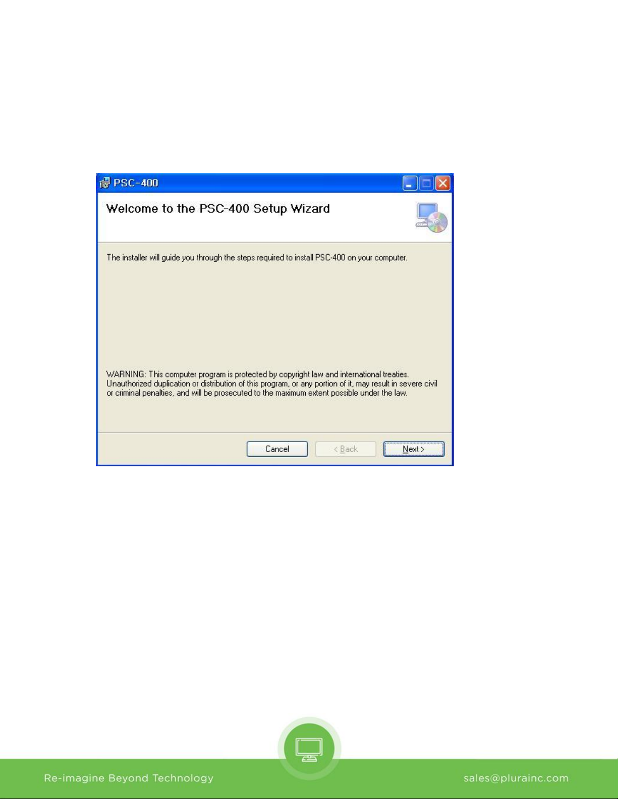
• To install the program on user pc, select “Run” installation file, and follow the “Plura System
Controller Setup Wizard” instructions.
After installation is completed, a shortcut button will be shown on the desktop and in the start menu.
3
Page 4
III. Contents of PSC – 400/500
1). Menu strip
a) Menu: Mode, New, Open Map, Save as…, Exit
- Mode: Edit Map, Start Control
- New: start a new Map
- Open Map: Load a control map from a saved file
- Save as…: Save the control map to file
- Exit: Exit
b) Edit Map: Properties, Control Map Wizard, Add Monitor, Delete Monitor, Add Page, Delete Page
- Properties : Set properties of monitor
- Control Map Wizard : Easy Set PSC-400 for user
- Add Monitor : Add one or more monitors
- Delete Monitor : Delete one or more monitors
- Add Page : Add one or more pages
- Delete Page : Delete one or more pages
c) Setup : User Level, Shortcut Keys, Network Configuration
- User Level : Select User Level, Administrator // Engineer // Operator
- Shortcut Keys : Select, Change or Delete Shortcut Keys
- Network Configuration : Search and select Network adapter
4
Page 5
- Function Key : Read, select or change Function Key
- GPI : Read, select or change GPI Key
- SFP Module : Easy Change SFP Module
- Video Wall : Set Video Wall
e) Tools : FPGA Express, Flash Express
- FPGA Express : Search and select monitor, Download FPGA
- Flash Express : Search and select monitor, Download Firmware
f) Help : About
- About : About PSC-400
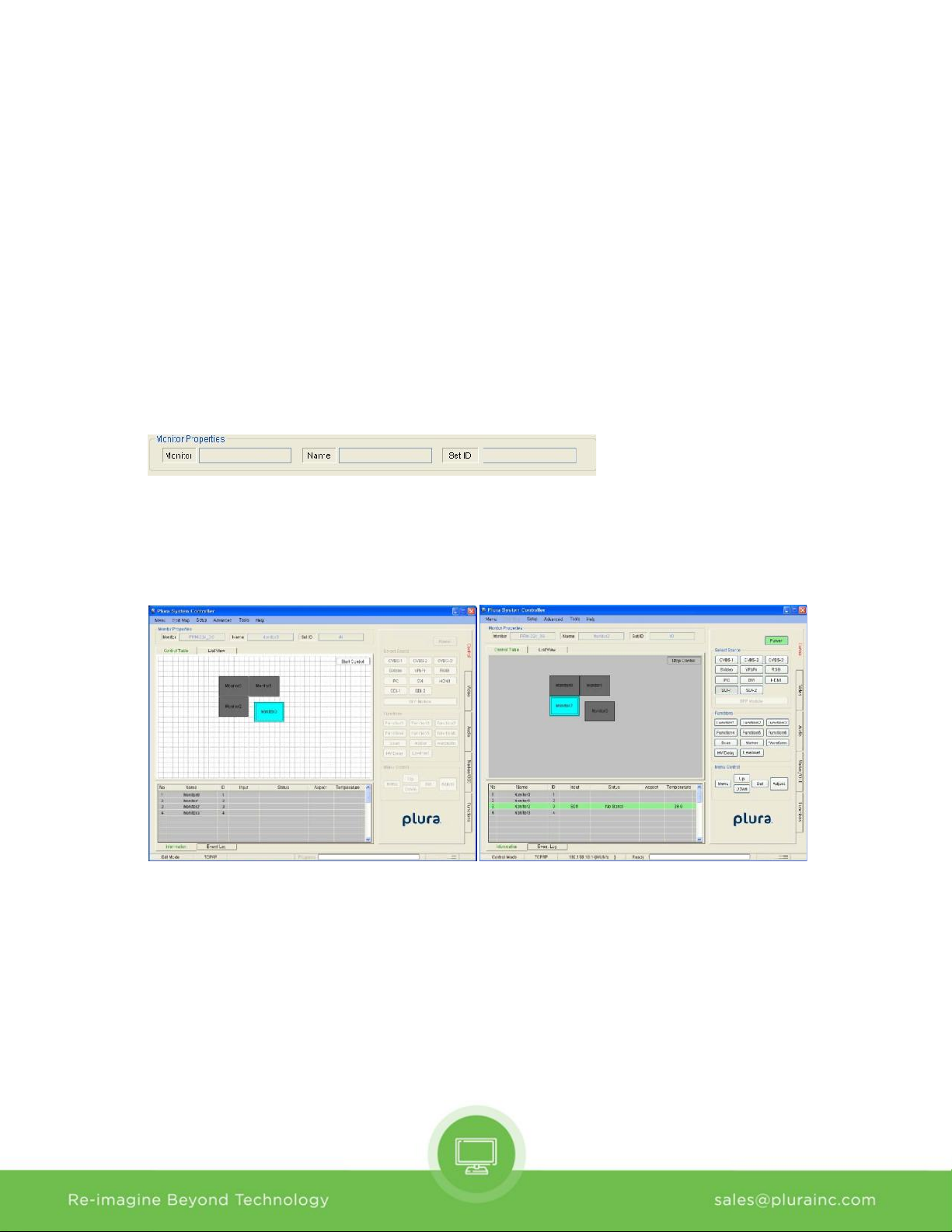
2). Monitor Properties Group
- Displays the selected monitor’s model, name and ID.
3) Control Table
- Displays currently opened control Map.
- User can edit the control map and control the monitor on this table.
- This table is changed according to the mode changing as below.
(Edit Mode) (Control Mode)
4) List View
- Displays list of currently opened control Map.
- User can edit and control the monitor.
d) Advanced : Function Key, GPI, SFP Module, Video Wall
5
Page 6
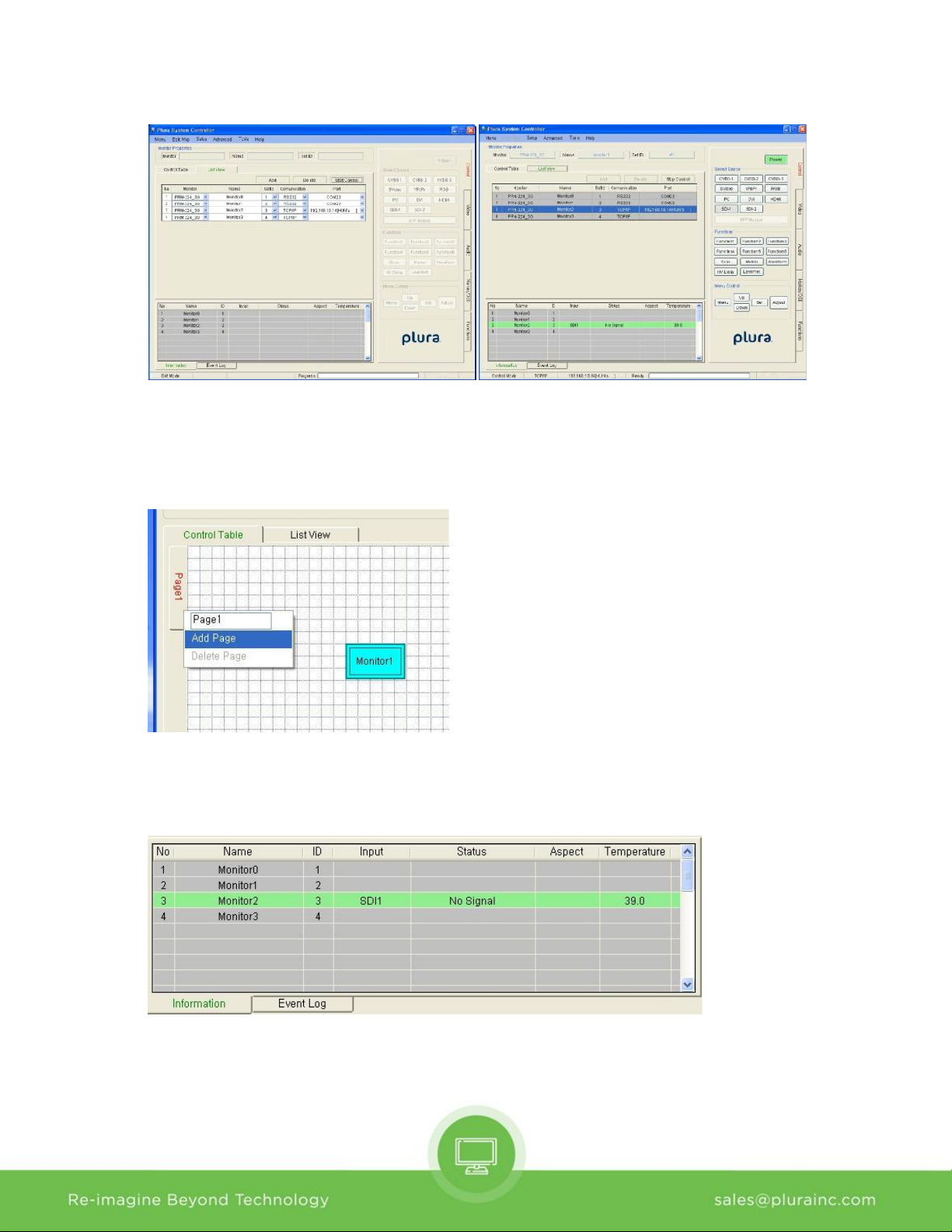
(Edit Mode) (Control Mode)
5) Page
- Make more pages, User can control multiple pages
- Click tab and Right-clicking mouse, can make more pages
6) Information
- Displays each monitor’s information which is added on control table.
- User can see the Monitor ID, Signal Locking status, Input resolution, Aspect and Board temperature.
7) Event Log
- It shows the major events that occurred in system controller.
- Clear: Clear the log window.
6
Page 7
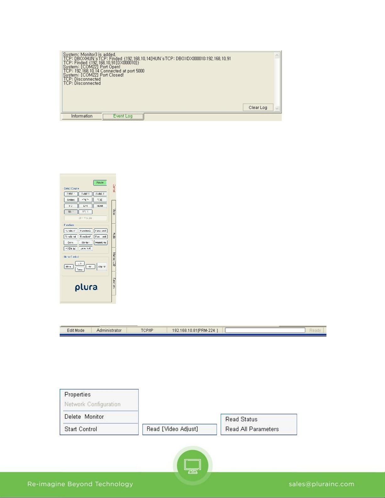
8) Controller Tap
- User can control the monitor easily thought this tap.
- Controller Tap is only available when monitor is selected in the control mode.
9) Status Bar
- It displays Mode, Interface, Com port or Target IP address, Progress bar and current time.
10) Context Menu
- Right-clicking or Double-clicking on Control Table or Controller Tap will bring up the commands used
to control.
7
Page 8
IV. Edit Control Map
- User can edit the control map in EDIT MODE.
- Edit mode is only to use the Editing map. User cannot control any monitor in this mode.
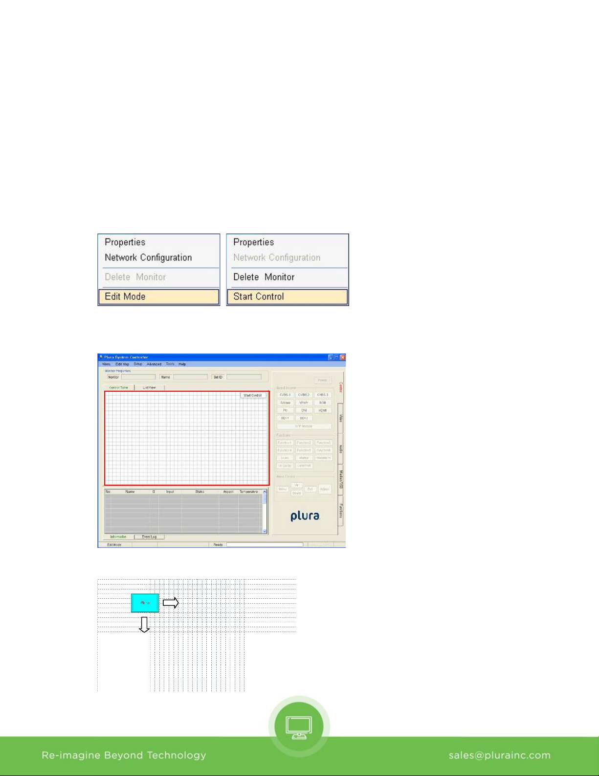
1) Start Edit Mode
- User can change to edit mode through Mode items on menu strip, context menu on control table or
mode changing button on control table.
- Below Context menu strip is opened by mouse right-clicking on the Control Table.
- It is changed depending on status of mode.
(Control mode) (Edit mode)
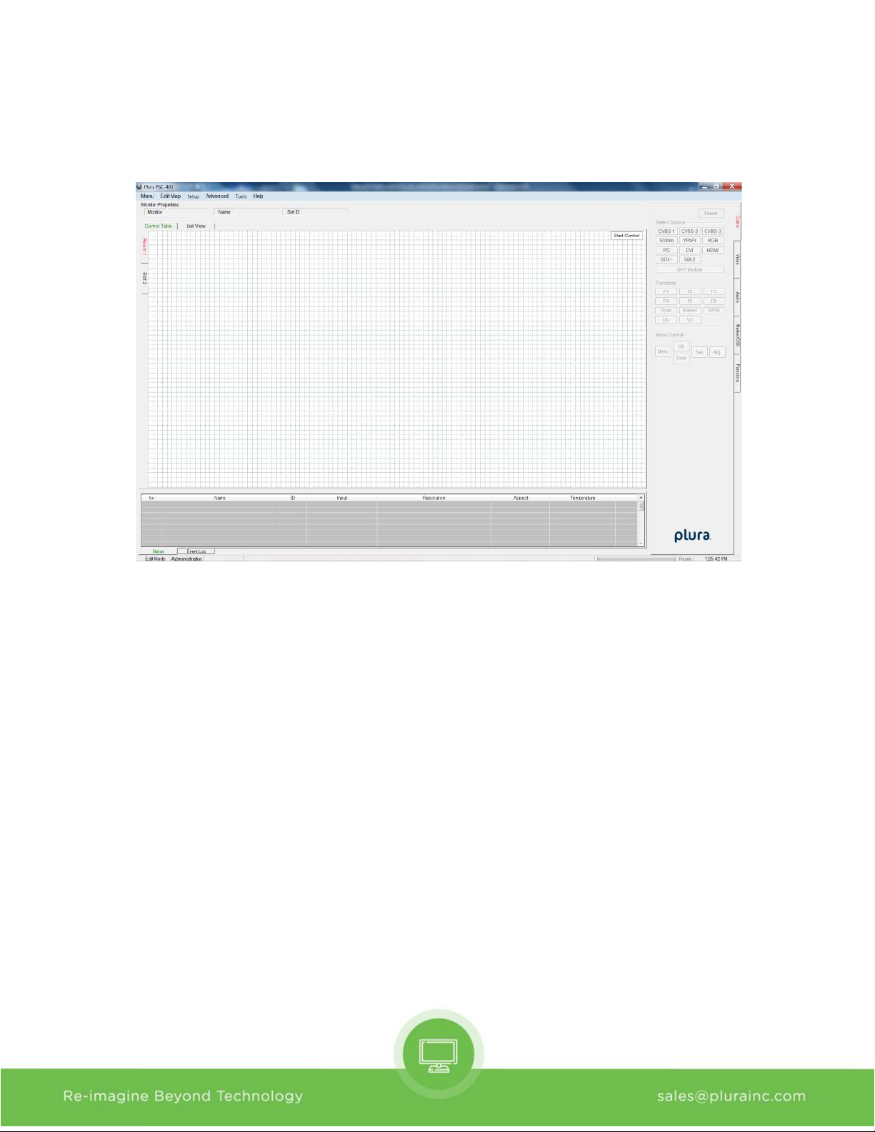
- If mode is edit state, Control table is grid pattern as below.
- In control table, user can locate the monitor icon any place.
8
Page 9
2) Open and Save Map
- User can save the control map and open the saved one.
- Filename extension is .pc3.
3) Add and Delete monitor
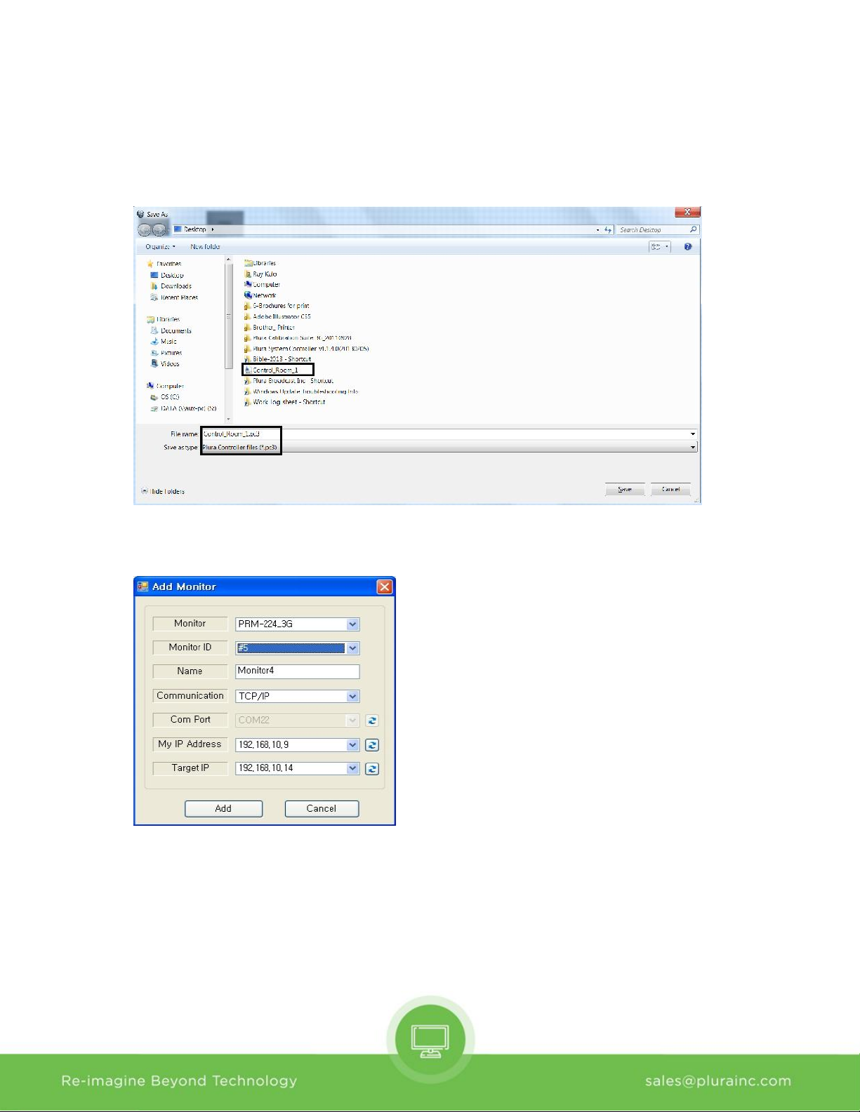
- User can add the monitor for use in control table by Add Monitor form as below.
- User can open the Add Monitor form by the Edit menu or context menu strip on control table.
a) Monitor: Select the target model. Icon size is changed by model.
b) Monitor ID:
- Select the target monitor’s ID number.
- If ID is different, User cannot control the monitor.
- Cannot select same ID with other monitors.
9
Page 10
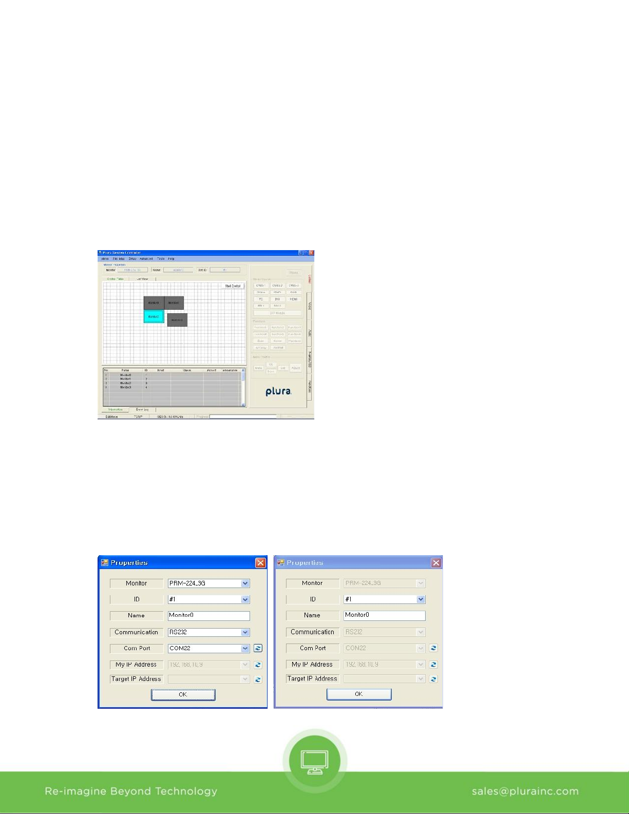
c) Name:
- It appears in the center of the monitor icon.
- Cannot make same name with other monitors.
d) Communication: select communication interface between RS232 and TCP/IP.
e) Com Port: select RS232 Comport of available in PC.
f) My IP Address: select PC IP address of available in PC..
g) Target IP: select target IP address of linked monitor.
h) Add and Cannel button: Add monitor or cannel the add monitor.
- If monitor is successfully added, user can see the monitor icon on control table and information as
bellow.
- User can delete the selected Monitor by Edit item on menu or context menu on control table.
4) Properties
- User can change all properties of selected monitor that already added on control table.
- User can open the properties form of the selected Monitor by Edit item on menu or context menu on
control table.
- It is changed depending on the mode
(Edit Mode) (Control Mode)
10
Page 11
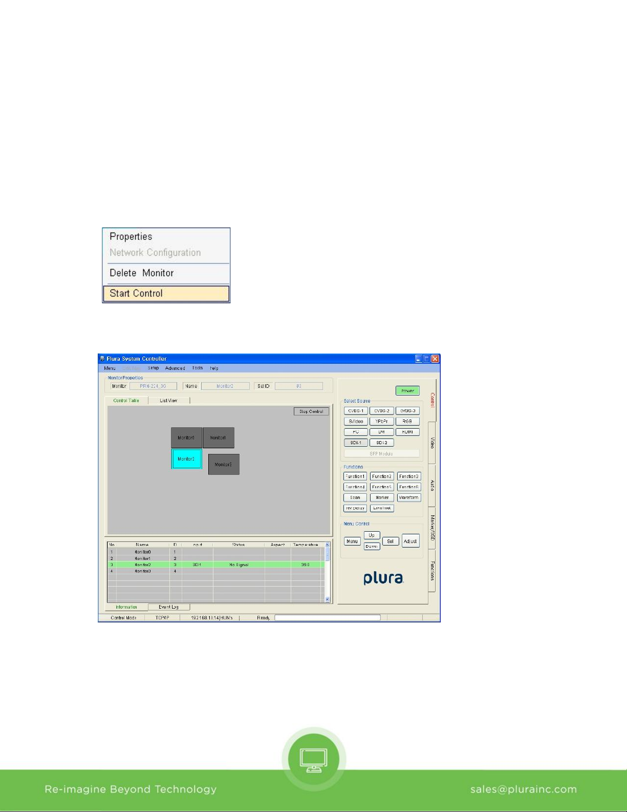
V. Control Mode
- User can control the selected monitor in this mode.
- Only for control, cannot edit.
1) Start Control
- User can select the control mode thought Mode items in menu strip, context menu strip or mode
changing button on control table.
- Context menu strip is opened by mouse right-clicking on Control Table.
- If mode is control state, Control table is changed as below.
11
Page 12
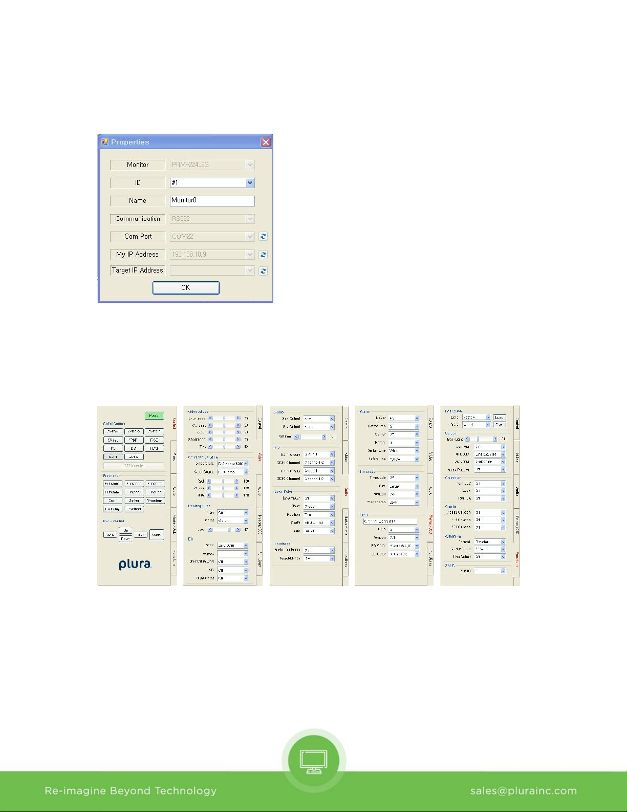
2) Properties
- User can only change ID and name through the properties form in this mode.
Properties form is opened by the Edit menu or context menu.
3) Controller Tap
- User can control the monitor thought this tap.
- Controller Tap is only available when monitor is selected in control mode.
- It consists of Control, Video, Audio, Marker/OSD and Functions Tap.
- Each controls are changed depend on model type. SFP module is only available in SFP model.
- User can read each parameter’s value from target monitor by context menu on control table or group
box. Each context menu as below is opened by mouse right-clicking or double-clicking.
12
Page 13
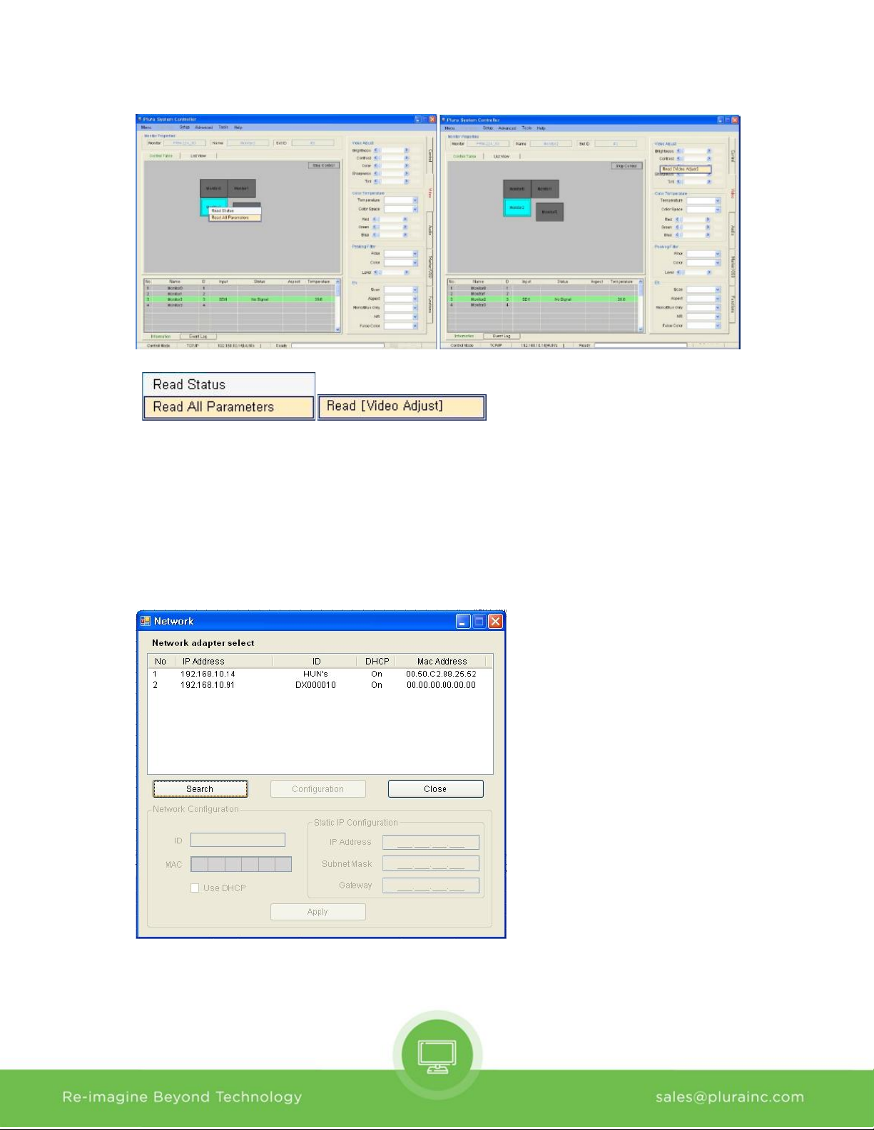
(On Icon of Control Table) (On Group Box)
- Read All Parameter: read all of parameter in system controller from selected monitor.
- Read [Video Adjust (Group Box name)]: To open this context menu, use the mouse right button to
click in group box.
4) Network Configuration
- Use this form to configure the network settings.
- Open the Network form on the Setup menu.
- Click the item on list to connect the network board.
- If connected, Configuration button is enabled.
- Network Configuration box is enabled with clicking the Configuration button.
13
Page 14
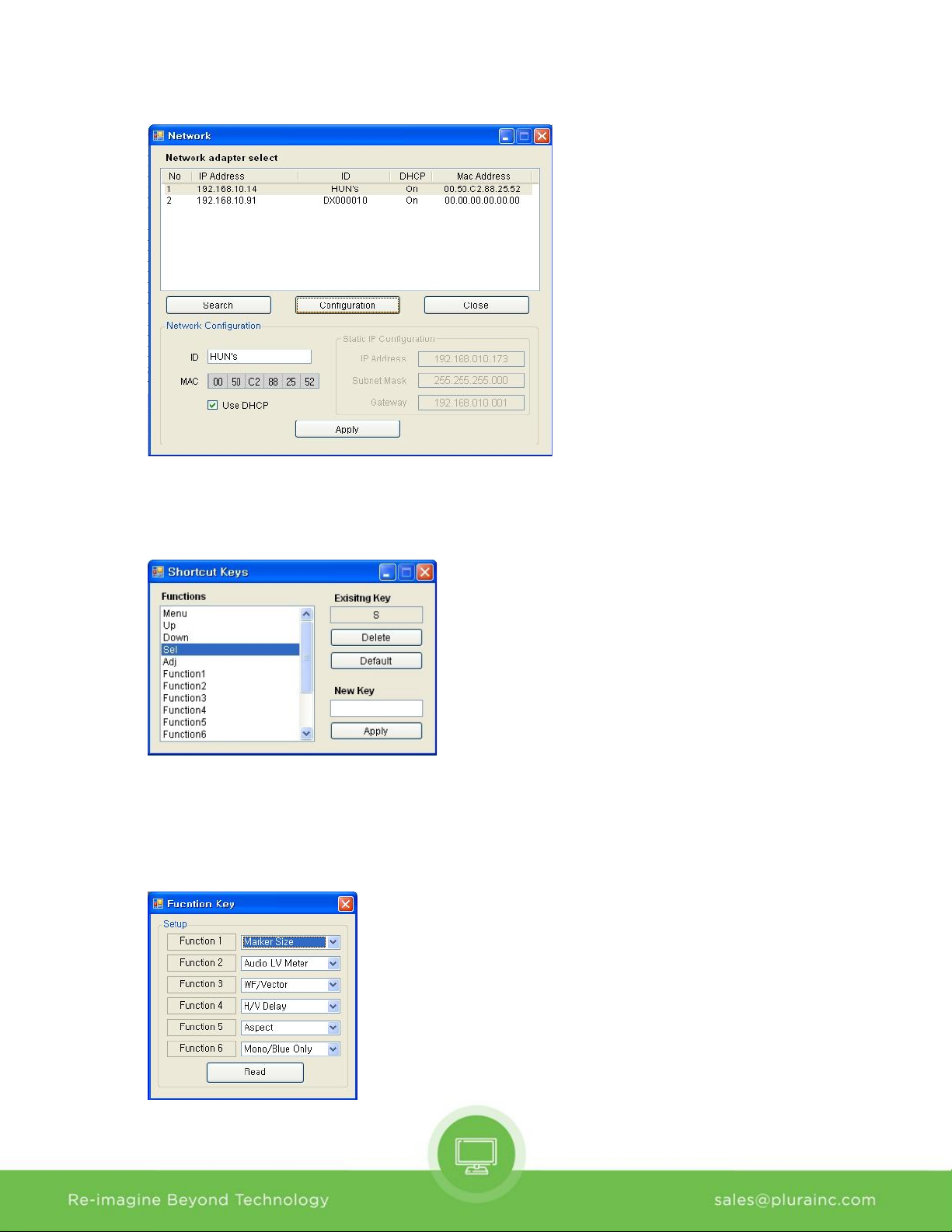
5) Shortcut Keys
- Shortcut keys save user having to click the button.
- User can set up the shortcut keys with this form on Setup menu.
6) Function Key
- User can open the Function Key setting form on the Advanced menu.
- Name Button: Same as function key on keypad.
- Combo Box: Select a wanted function. It can be changed depending on the model.
14
Page 15
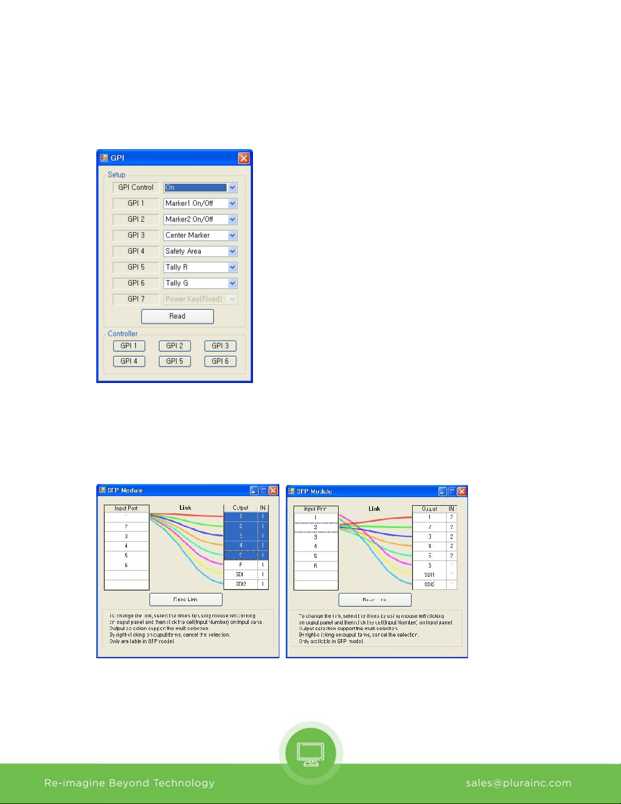
7) GPI
- User can open the GPI setting form on the advanced menu item.
- Setup: User can select GPI function.
- Controller: simulated GPI controller.
8) SFP Module
- User can open the SFP Module form on the Advanced menu item.
- Only available in SFP model.
- To change the link, select the items by using mouse left-clicking on output panel and the click the
cell (input number) on Input panel
15
Page 16
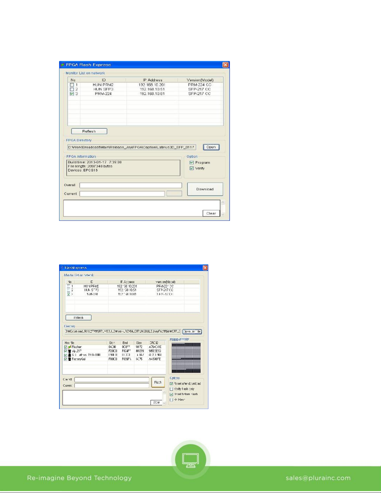
9) FPGA Express
- User can open the FPGA Express on the Tools menu.
- Select Monitor on network, Open FPGA Directory and select FPGA pof file,
- Download FPGA
10) Flash Express
- User can open the FLASH Express on the Tools menu.
- Select Monitor on network, Open Directory and select Firmware inf file,
- Download Firmware
16
Page 17
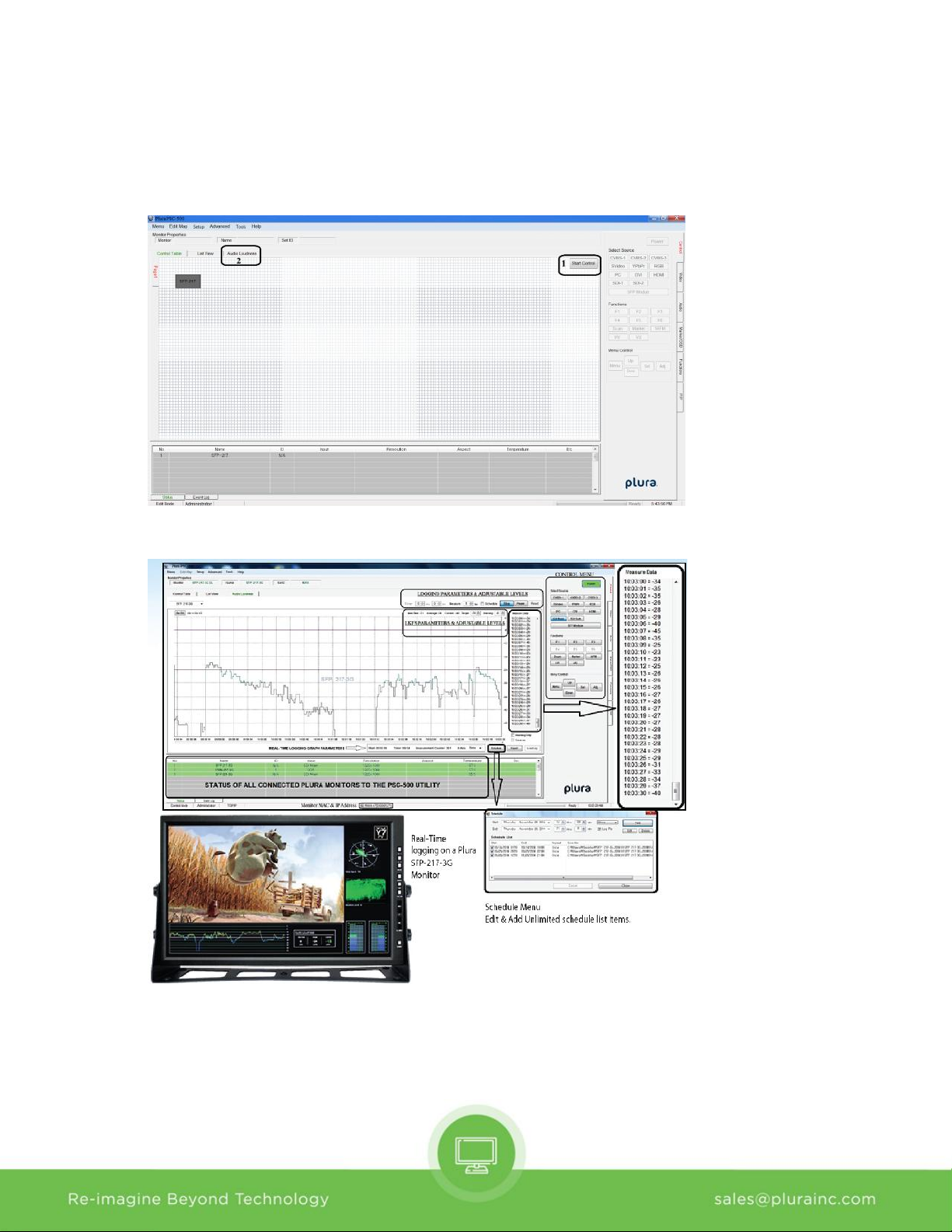
I. Audio Loudness (LKFS) – PSC-500 ONLY
- User can Monitor & Log Audio Loudness for the selected monitor.
- Select start control and then Audio Loudness tabs.
- Select the monitor from the drop down menu to begin monitoring and logging.
17
Page 18
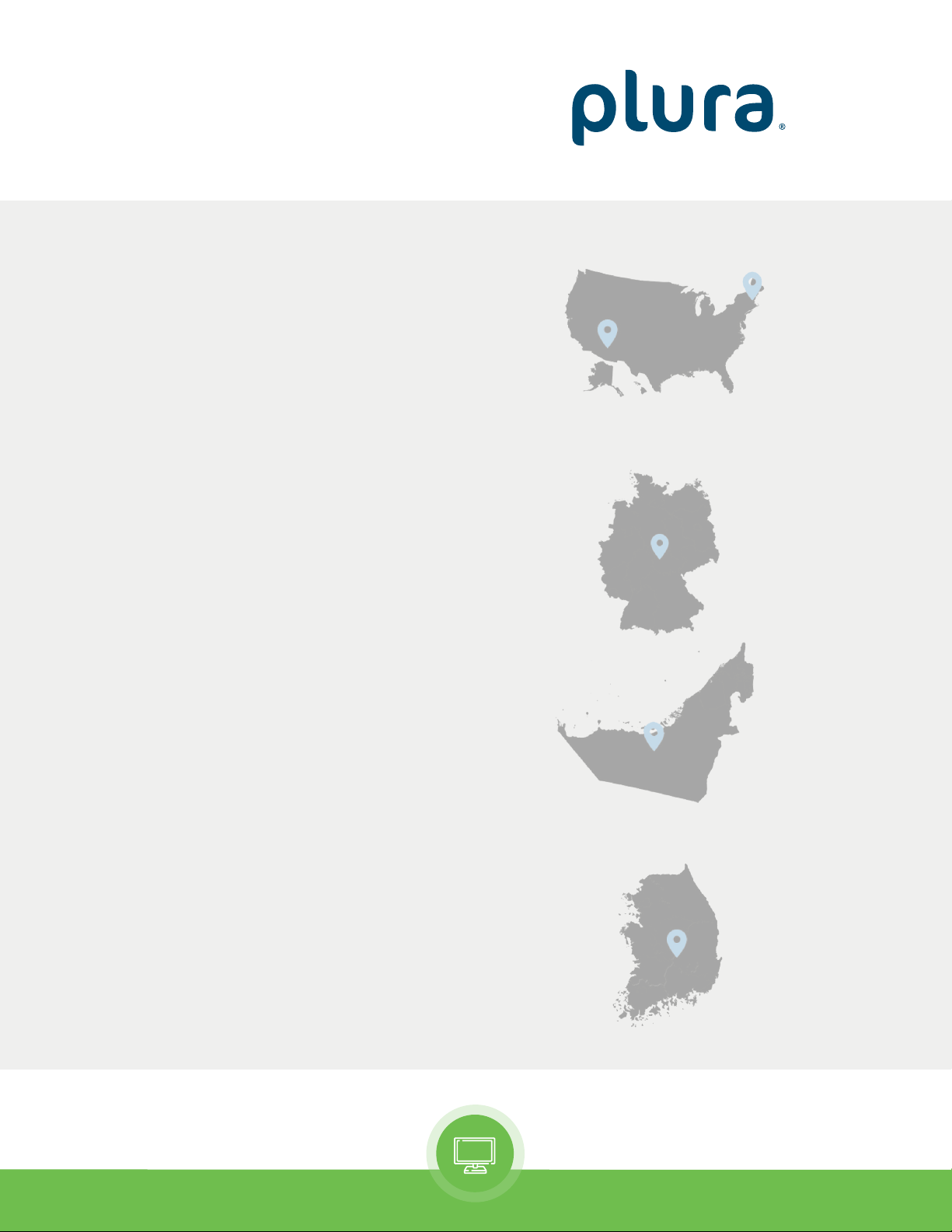
Contact Us
Corporate Offices:
Plura Broadcast, Inc.
Ph: +1-602-944-1044
Plura Europe GmbH
Ph: +49-6725-918006-70
U.S.A.
GERMANY
Plura MEA
Ph: +971-50-715-9625
Plura Asia
Ph: +82-10-6688-8826
U.A.E.
S. KOREA
Re-imagine Beyond Technology [email protected]
 Loading...