

Page 1
Installation
Instructions
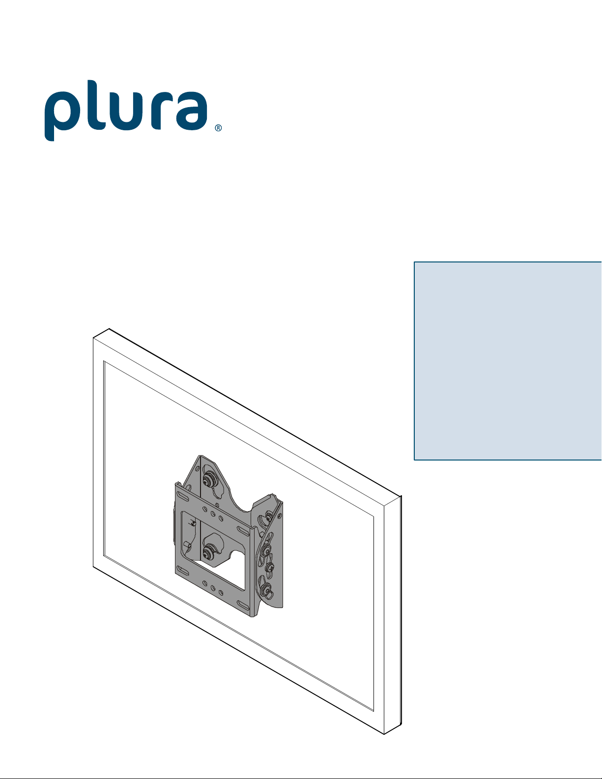
Small Flat Panel
PBM-WMS
Tilt Wall Mount for
17”, 19”, 20” 24”
Monitors
Page 2
PBM-WMS Installation Instructions
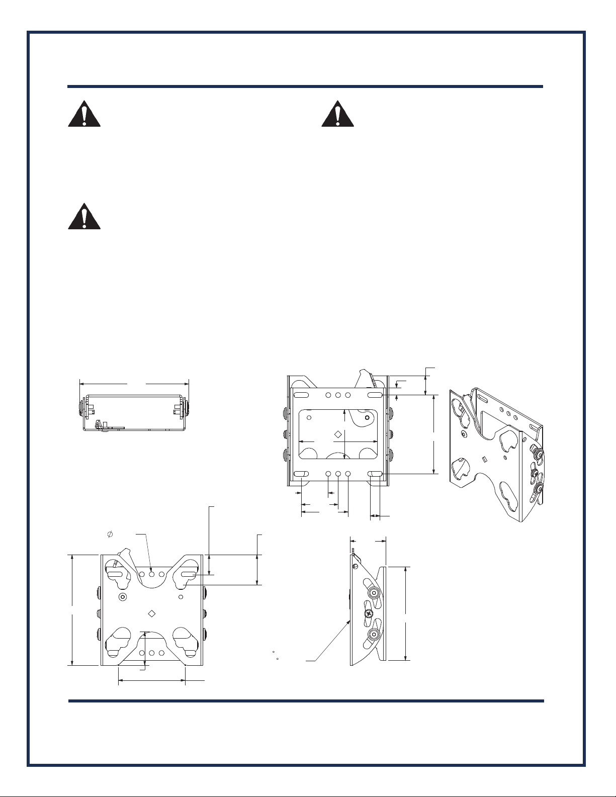
5.61
4.75
UP
15
DOWN
.50
4.00
2.50
4.00
.38
.99
1.38
1.88
2.38
WARNING: Failure to read, thoroughly understand, and
follow all instructions can result in serious personal injury,
damage to equipment, or voiding of factory warranty! It is the
installer’s responsibility to make sure all components are
properly assembled and installed using the instructions
provided.
WARNING: Failure to provide adequate structural strength
for this component can result in serious personal injury or
damage to equipment! It is the installer’s responsibility to
make sure the structure to which this component is attached
can support five times the combined weight of all equipment.
Reinforce the structure as
required before installing the
component. The wall to which the mount is being attached
may have a maximum drywall thickness of 5/8" (1.6cm). Do
not install drywall anchors into the seam between drywall
pieces.
DIMENSIONS
5.56
WARNING: Exceeding the weight capacity can result in
serious personal injury or damage to equipment! It is the
installer’s responsibility to make sure the combined weight of
all components attached to the mount does not exceed 45 lbs
(20.4 kg) for wood stud installation OR 30 lbs (13.6 kg) for
drywall installation. Use with products heavier than the
maximum weight indicated may result in collapse of the
mount an
d its accessories causing possible injury.
.25 x6
1.69
100mm
MOUNTING
3.38
1.02
1.52
75mm
MOUNTING
FACE TILTS
5
1.82
2 of 7
Page 3
PBM-WMS Installation Instructions
Pencil Mark
Marcar con lápiz
Stiftmarkierung
Marcar com lápis
Segno a matita
Potloodmerkteken
Marquage au crayon
Drill Hole
Perforar
Bohrloch
Fazer furo
Praticare un foro
Gat boren
Percez un trou
Adjust
Ajustar
Einstellen
Ajustar
Regolare
Afstellen
Ajuster
1/8" (wood stud)
3/8" (drywall)
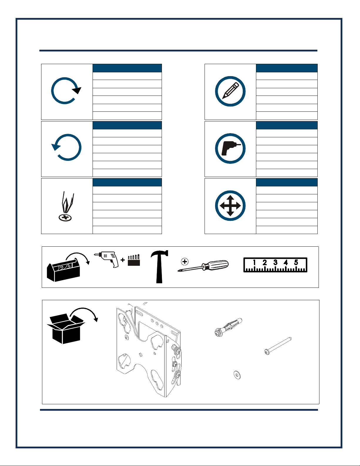
A (1)
[PBM-WMS Assembly]
B (4)
10-24
[Hollow wall anchor]
C (4)
#10
D (2)
#10 x 2-1/2"
Tighten Fastener
Apretar elemento de fijación
Befestigungsteil festziehen
Apertar fixador
Serrare il fissaggio
Bevestiging vastdraaien
Serrez les fixations
LEGEND
Loosen Fastener
Aflojar elemento de fijación
Befestigungsteil lösen
Desapertar fixador
Allentare il fissaggio
Bevestiging losdraaien
Desserrez les fixations
Phillips Screwdriver
Destornillador Phillips
Kreuzschlitzschraubendreher
Chave de fendas Phillips
Cacciavite a stella
Kruiskopschroevendraaier
Tournevis à pointe cruciforme
TOOLS REQUIRED FOR INSTALLATION
#2
PARTS
3 of 7
Page 4
2
4
x 2
x 2
5
(D) x 2
(A)
(C)
3
4
x 4
(B) x 4
5
x 4
2
Drywall
Anchor barb
Anchor
Anchor not
collapsed
collapsed
PBM-WMS Installation Instructions
4 of 7
INSTALLATION
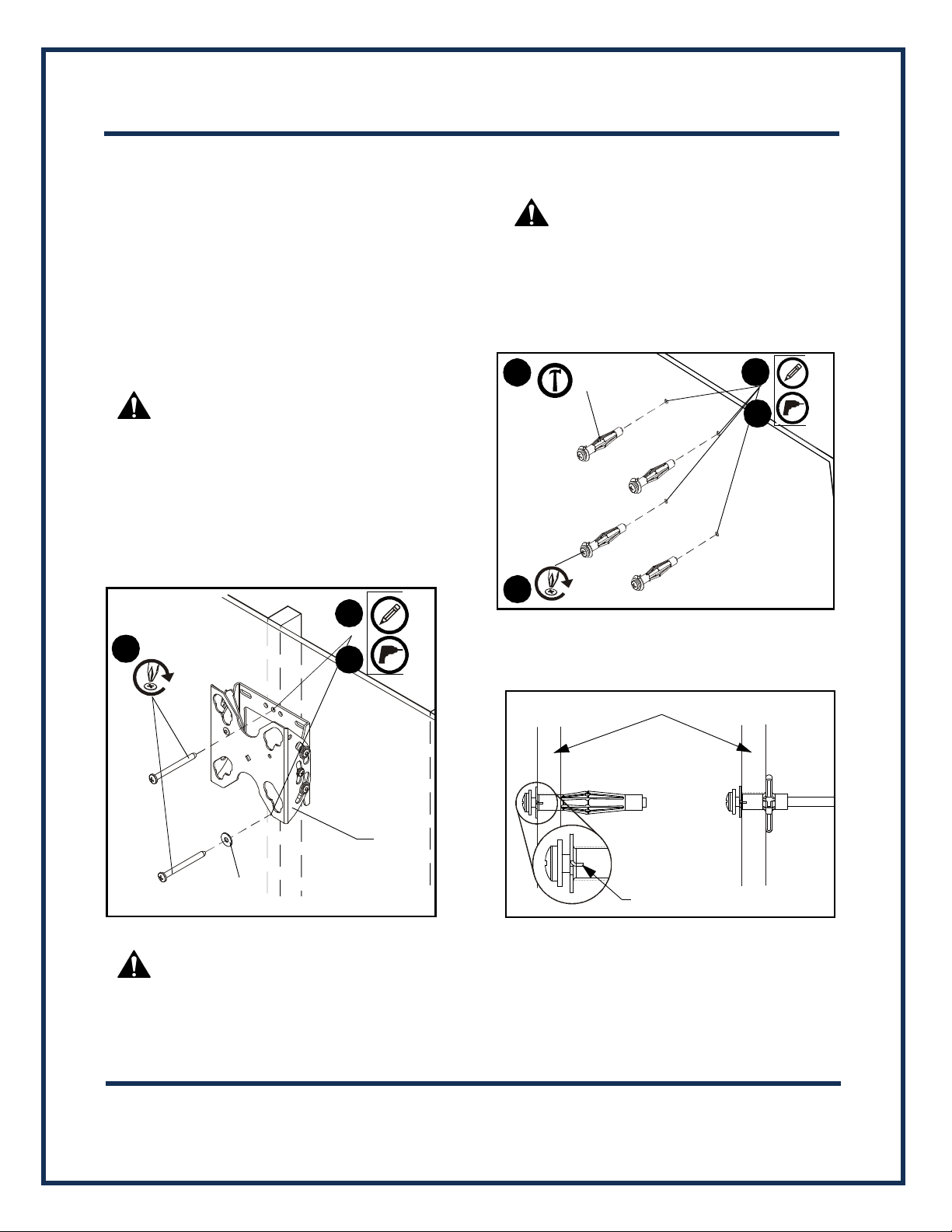
The PBM-WMS may be installed on either a single 2" x 4" wood stud,
or on drywall (1/2" minimum thickness). The PBM-WMS allows a tilt
range from 5° up to 15° down.
Install Mount to Single Wood Stud
1. Determine approximate mounting location, keeping in mind
the display size.
2. Use a stud sensor to locate applicable wood stud. Mark
location with a pencil.
Level PBM-WMS assembly (A) at desired height and, using it as a
3.
template, mark the location of upper and lower pilot holes.
Ensure marks are in the center of wood stud.
NOTE: Mount can provide ±1/2" of lateral shift by using mount
4. Drill 1/8" pilot holes. Ensure pilot holes are straight.
5.
holes on either
WARNING:
electrical wires or cables can cause DEATH or SERIOUS
PERSONAL INJURY! ALWAYS make certain area behind
mounting surfaces is free of electrical wires and cables
before drilling or installing mount fasteners.
Fasten
PBM-WMS
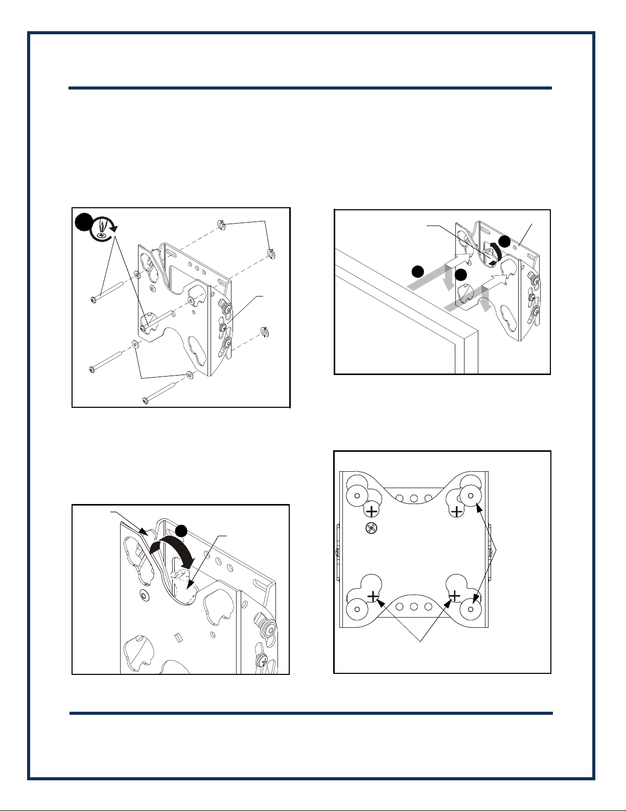
screws (D) through two #10 washers (C), PBM-WMS (A), and
drywall (not shown) and install into pilot holes.
(See Figure 1)
side of vertical center line.
ELECTRICAL SHOCK HAZARD! Drilling into
to wood stud using two #10 x 2-1/2" Phillips head
Level PBM-WMS assembly (A) at desired height and, using it as a
2.
template, mark the location of the four anchor holes (one in
each corner slot).
WARNING: ELECTRICAL SHOCK HAZARD! Drilling into
electrical wires or cables can cause DEATH or SERIOUS
PERSONAL INJURY! ALWAYS make certain area behind
mounting surfaces is free of electrical wires and cables
before drilling or installing mount fasteners.
3. Drill 3/8" anchor holes. Ensure holes are straight and
completely through drywall. (See Figure 2)
4. Gently tap anchor (B) into anchor hole. Anchor barbs
should be fully engaged in drywall (See Figure 3).
Figure 2
Figure 1
Install Mount to Drywall
WARNING: Drywall must be a minimum thickness of 1/2"
and a maximum thickness of 5/8". Do not install drywall
anchors into the seam between drywall pieces.
1. Determine approximate mounting location, keeping in mind
the display size.
Figure 3
5. Using Phillips screwdriver, tighten anchor screw until
anchor has fully collapsed against back side of drywall.
(See Figure 2) and (See Figu
re 3)
NOTE: Anchor screw will feel tight until anchor begins to
collapse. Screw will then turn easier for many turns.
Screw will feel tight when anchor has fully collapsed.
Page 5
(B)
8
Anchor
(C) x 4
(A)
screws
x 4
1
Latching
flag closed
Latching
flag open
2
3
Display
(A)
4
Latching
flag
Button location for
75mm x 75mm
pattern (4 places)
NOTE: Display not shown for clarity.
Button location
for 100mm x
100mm pattern
(4 places)
PBM-WMS Installation Instructions
5 of 7
6. Repeat Steps 4 and 5 for remaining anchors.
7. Remove and retain anchor screws from anchors (B).
NOTE: Anchors (B) may come with small washers which may
be left on the screw or discarded. These small washers
do NOT replace washers (C).
8. I
nsert anchor screws through washers (C), PBM-WMS (A) and
install into collapsed anchors (B). Tighten until secure.
(See Figure )
2. Lift and maneuver display such that all mounting buttons fit
into openings on PBM-WMS (A). (See Figure 6)
3. Lower display firmly into place. Ensure each mounting
button has fully seated in the opening (See Figure 6)
Close latching flag by rotating flag counterclockwise on PBM-WMS
4.
(A). (See Figure 6)
Figure 6
Figure 4
NOTE: Proper interface must be attached to display. Follow
Open latching flag by rotating flag clockwise on PBM-WMS (A).
1.
(See Figure 5)
Install Display to Mount
instructions included with interface assembly.
Figure 5
NOTE: Mounting buttons are shown in the 100mm x 100mm
pattern. PBM-WMS (A) will also accommodate a 75mm x
75mm pattern. (See Figure 7)
Figure 7
Page 6
NOTE: Display not shown for clarity.
5° Tilt Up
15° Tilt Down
1
2
3
PBM-WMS Installation Instructions
6 of 7
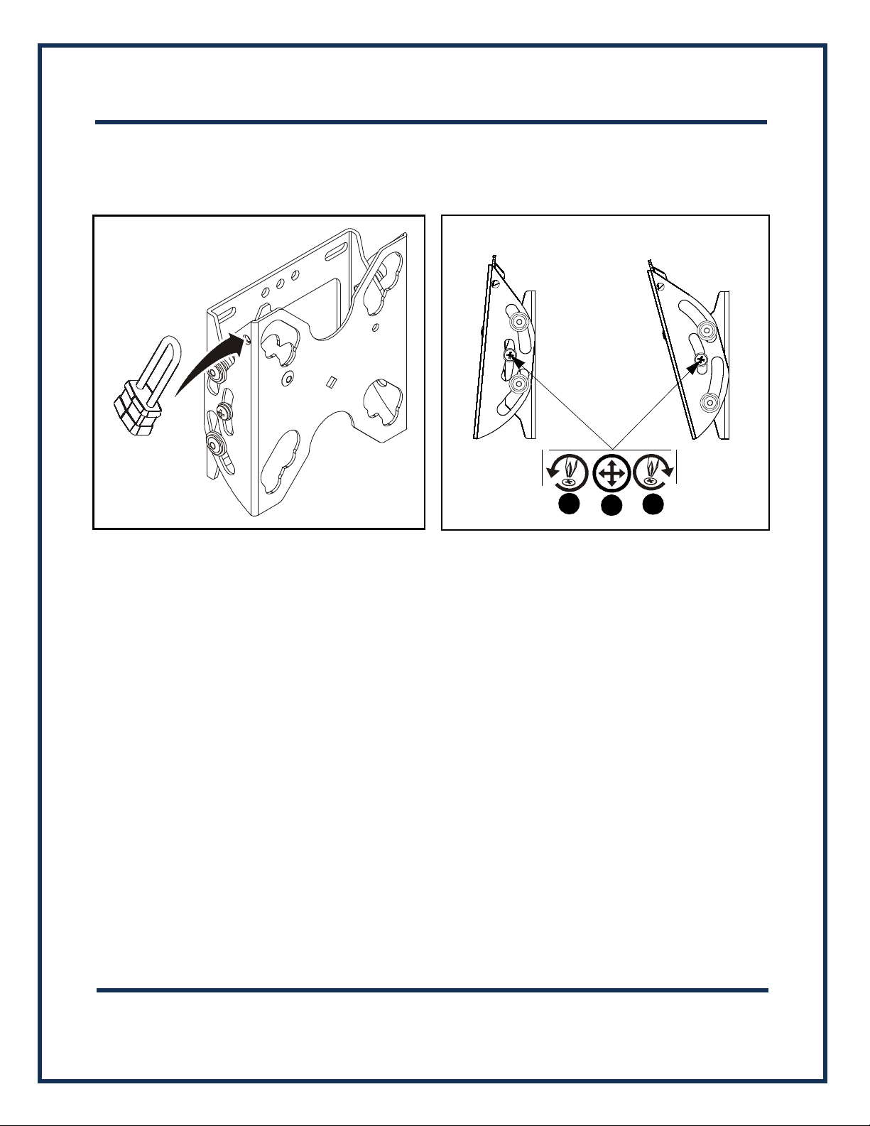
NOTE: An optional padlock may be used to secure latching flag
in place. (See Figure 8)
Figure 8
5. Connect cables to display as required.
Figure 9
Removing Display from Mount
1. Disconnect all cables from display.
2. Open latching flag by rotating flag clockwise on PBM-WMS.
3. Lift and maneuver display mounting buttons out of button
openings.
Adjusting Tilt
1. Loosen adjusting screws on each side of display (See
Figure 9).
2. Adjust tilt as desired.
3. Retighten adjusting screws.
Page 7

Plura Broadcast, Inc. - West Coast
1930 W. Quail Ave.
Phoenix, AZ 85027
Tel: (602) 944-1044
Fax: (602) 324-9688
www.plurabroadcast.com
Plura Broadcast, Inc. - East Coast
67 Grand Avenue
Massapequa,NY 11758
Tel: (516) 997-5675
Fax: (516) 593-7900
 Loading...