

Plumis Automist Series Technical Manual
Page 1 of 27
Automist
TM
Technical Guide
Product specication and technical results from a test suite at BRE Global to
enable building control and re industry professionals to assess or specify Automist.
Plumis Ltd.
Seamless Fire Protecon
www.plumis.co.uk
A technical guide for:
- Building Control
- Fire Industry Professionals
New Edition
Version 2.5.0
RD171

Page 2 of 27
1 This Document Page 3
2 Introduction to Automist Page 3
3 System Diagram Page 4
4 Automist Operation Page 6
5 Quality Assurance Page 6
6 Components and conguration Page 7
7 Fire suppression within a holistic approach Page 9
8 Fire Performance and Regulations Compliance Page 10
9 Use of Automist Page 15
10 Specifying Automist Page 17
11 Conclusions Page 19
12 Appendix Page 20
The aim of Automist is to aid in the detection and control of dwelling res and thus provide improved protection
against injury, life loss and property damage. When correctly installed and maintained in accordance with its
instruction manual, Automist is designed to operate in a manner similar to that demonstrated in the testing
performed at BRE Global, subject to a reliable power and water supply and a correctly operating alarm input. The
effectiveness of Automist is however dependent on factors such as the size of room, detection method, environmental
conditions, available fuel, the source of the re, availability of ventilation, human behaviour and health, distance
to the re, time to activation and the actions of the emergency services upon arrival. Plumis therefore cannot make
warranties regarding detection, control, suppression or extinguishment of res, nor the prevention of injury, death
or property damage.
Contents

Page 3 of 27
Automist is a re suppression appliance designed for residential use. Its primary application is in the gap
between standardised sprinkler systems, which are designed to provide suppression to every room in a
property, and building and housing regulations, which in many circumstances require re suppression in a
single open-plan “access room”.
All major UK guidance documents on residential re safety, including Approved Document B, The LACoRS
guide, and Scottish Building Regulations, recognise re suppression as a compensatory solution for layouts
where the provided compartmentation is not adequate on its own, and divide the solutions into two
categories:
• Standardised products, generally “off patent” using long-established technologies;
• Innovative products, which have not yet been standardised, often patent protected and proprietary.
In both cases, it is essential that products have been adequately tested. For Standardised products,
strengths and weaknesses need not be evaluated for every project, as assessors can rely on the standards to
short-cut some of the regulatory formalities. For Innovative products, a similar short-cut is available in the
form of the LABC Registered Details Scheme.
Automist is covered by Registered Detail (RD171). Those wishing to
compare Automist directly to a conventional BS9251 sprinkler system in
greater detail should refer to section 8.2 of this guide.
The recent introductions of BS9991 and PD7479 illustrate the limitations
of an approach to re safety driven wholly by product categories; the new
standards have a broader reach, allowing Fire Engineering skills to be
applied to residential re safety strategy, inherently embracing the use of Innovations in re safety through
rigorous analysis of limitations and solutions.
The objective of this guide is to provide information on the performance, specication and installation
of Automist. With this guide as a route map, speciers and approvers can feel condent in specifying
Automist.
Intended as a more practical and affordable alternative to sprinklers, Automist uses a high pressure pump
to generate a ne water mist from nozzles mounted under a standard tap, on a work surface or in a wall.
In an extensive BRE test programme, Automist was found to render a lethal environment survivable.
Automist is a water mist innovation which provides developers with greater design freedom and exibility
of layout, in new builds, refurbishments or loft conversions.
1 This Document
2 Introduction to Automist
1. The LABC Registered Detail logo is a collective mark registered by LABC.
Page 4 of 27
Two examples of generic system layouts are detailed on the following pages. As an “pre-engineered”
solution which is not covered within any one British Standard the following system layouts are proposed
as our recommendations, however these may need modication during the course of negotiation with
approving authorities with regard to a specic project specication.
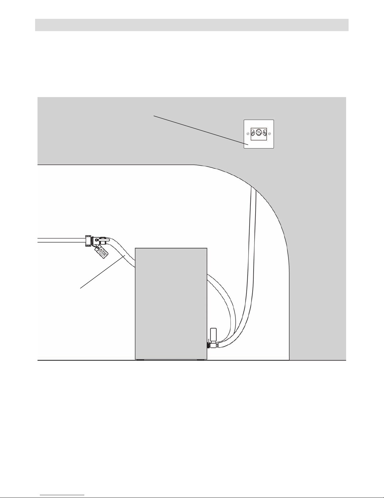
a) Automist wall-mount kit (3N)
3 System Diagram
A discreet single-gang wall box
holds the water mist spray head
in place.
The pump can be housed in a
cupboard, under a staircase or
within a custom box unit.
Stainless
steel braided
3/4” water supply
Page 5 of 27
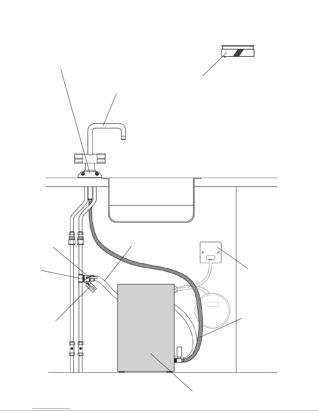
b) Automist under-tap kit (4N)
Assembled Automist emitter
- outer cover and o-ring
- manifold and two o-rings (base & upper)
- six protective caps
- four watermist nozzles
High
pressure
hose
Stainless steel braided
3/4” water supply
hot & cold water
supply pipes
Fused
connection
unit on a
separate
circuit
Automist
supply label &
cable tie
Wired or wireless heat
alarm with NC and NO
relay functionality
Standard
monobloc tap
¾” single
check valve
¾”
washing
machine
outlet with
isolation
valve
Automist
Pluvia Pump

Page 6 of 27
In the event of a re, the system is triggered automatically by a heat alarm or a re panel output. Heat
detection is recommended for kitchens in Approved Document B, and effectively eliminates nuisance
activation. Unlike conventional sprinklers, Automist can be stopped manually by pressing a button on
its control panel or by cutting power to the independent circuit on the consumer unit (marked with an
indicator sticker). As Automist uses much less water than a traditional sprinkler system, water damage
in the event of activation is minimised. Where desired, manual activation can also be provided through a
manual call point.
Once triggered, a pump drives mains water through the unique nozzle unit, quickly lling the room volume
with a dense fog. Water mist removes heat and displaces oxygen from the re zone, resulting in re control,
suppression or extinguishment. The intention is to lower the temperature and the accumulation of toxic
gases, thereby reducing damage and increasing survivability.
Adding water to a chip pan re can greatly exacerbate the re; the same is not true for water mist as the
updraught from the ame and the evaporation of the tiny droplets prevents water from reaching and
collecting in the pan.
The water mist technology also has benets for suppressing a greater range of re scenarios, particularly
res that are shielded from the nozzle release point.
Concept
• Independently tested - Objectively and extensively tested by BRE Global (further details in
Appendix)
• All concept proposals are underpinned by British Standard re engineering justication.
Equipment & Components
• CE marked - Meets EU consumer safety, health & environmental requirements
• Water Regulatory Advisory Scheme Approved - Automist re suppression system was examined,
tested and found, when correctly installed, to comply with the requirements of the United Kingdom
Water Byelaws (Certicate number 1102330)
Installation
• Installation - Automist should be specied, commissioned and signed-off by Plumis or an Accredited
Reseller. Each installer is fully trained to ensure that every project is installed to the very highest
standards, receiving a Plumis Certicate of Approval on successful completion of their training.
4 Automist operation
5 Quality Assurance
Page 7 of 27
Automist should be mains fed with a reliable water supply:
• 6 l/min ow
• 1-10 bar pressure at pump inlet
• Standard BSP ¾” connection. For life safety applications exposed or partially exposed pipework
must be in copper or steel for robustness.
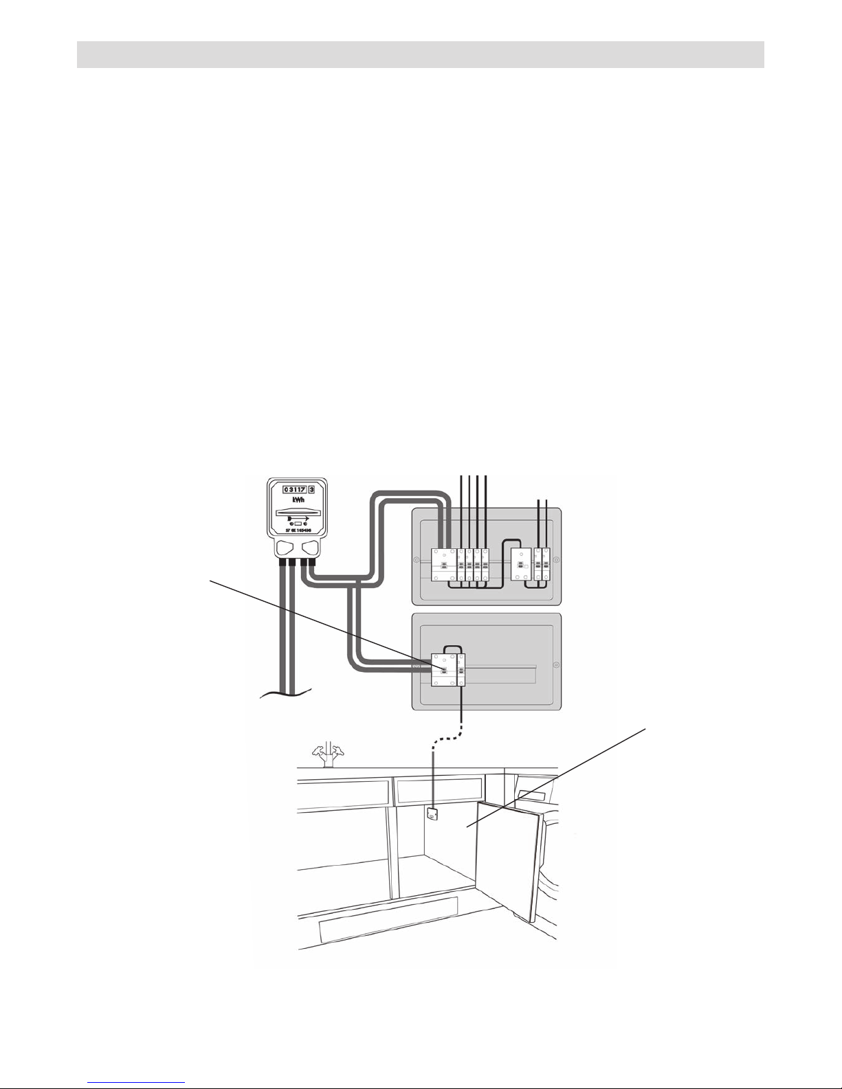
The Automist pump should be:
• Proper air circulation must be provided. The system requires there to be a minimum 100 mm gaps
are gap between the pump perimeter and the enclosures.
• Protected electrically by suitable fusing and powered by an independent circuit either via a delayed
action RCD or no RCD (1.7kW, 230V and 50Hz) with an unswitched fused connection unit with
ex outlet. FP200 re rated power cable must be used to supply the unit. If the consumer unit is
located in the protected area it should be shielded by a fuse box electrical cover unit tested to BS476
Part 22 (1987) and EN1364-1 (1999).
6 Componentsandconguration
under sink
cupboard
separate circuit
Example:

Page 8 of 27
The Automist unit will be activated by an alarm which will ensure that:
• Audible warning is provided throughout the protected area.
• In addition to Automist’s integrated sounder, we recommend that the detector or alarm system
that activates Automist also includes its own sounder.Guidance on re detection in dwellings is
contained in BS 5839: Part 6.
• Automist must not be activated by an early warning interlinked system (which might include smoke
alarms). A separate alarm circuit should be used or provisions should be made so that a smoke
alarm can sound the heat alarm connected to Automist but will not trigger the pump unit.
• Where a single Automist unit is used to protect more than one area by use of multiple mist heads,
the activating alarms must be interlinked so that any heat alarm sounding in the protected areas
will activate the Automist unit. Where multiple Automist units serve a single area, these must be
similarly interlinked with a separate relay output provided for each Automist unit.
• Where a re resisting construction separates two protected areas with one or more Automist units
serving each area, it is not normally necessary to interlink the activation between these separate
areas.
Installation ow valves:
• Check valve should be installed to ensure back ow protection to the mains water (supplied in kit).
• Approved Isolation valves should be included to shut off the Automist system from the mains. The
valves should be labelled with the included Automist supply warning labels.
• Priority valves are not normally required but should be used in circumstances where the water
supply may otherwise be inadequate.Electrical components used within the installation must.
• Comply with the relevant guidance in BS 5839 Part 6.

Page 9 of 27
A re suppression device like Automist aims to control and suppress res, signicantly reducing the risk
of injury, life loss and property damage by maintaining tenable conditions for as long as possible while
occupants evacuate. This is achieved in several ways:
• Reduction of room temperature in the region of the re. Water mist devices achieve this by
consuming much of the re’s energy in converting water to steam.
• Reduction of smoke and toxic gases. Water mist devices achieve this by the production of copious
amounts of steam in the immediate vicinity of the re, locally excluding oxygen, reducing
temperatures and thus inhibiting the combustion reactions of the re.
• Fire growth is restricted. This is achieved through the reduction in temperatures and slowing of
combustion reactions.
• Flashover prevention. By constraining room temperatures to around 100°C or less, the rapid
ignition of all combustible items in the rooms is prevented.
• Providing cooling to structural elements in the re compartment allows them to perform their
function for longer.
Utilising Automist’s benecial suppression capabilities as part of a package of building design measures
may offer an alternative, more exible and desirable solution to those prescriptive approaches offered by
design guidance such as Approved Document B.
7 Fire suppression within a holistic approach
 Loading...