


Automist® Fixed Wall
Head Handbook
Version 1.2.3
The Automist Fixed Wall Head Handbook is designed to
provide Accredited Automist Installers with essential
information regarding specification, installation,
maintenance and commissioning of the Automist fire
protection device.
Supersedes – Automist Fixed Wall Head Handbook Version 1.2.2

Automist® Fixed Wall Head Handbook v1.2.3
Plumis Ltd Copyright © 2017. All Rights Reserved. Page 2 of 41
®
Contents
INTRODUCTION TO THE FIXED WALL HEAD SYSTEM ............................................................................................... 4
Introduction ................................................................................................................................................................... 5
Automist operation ....................................................................................................................................................... 6
The Automist System .................................................................................................................................................... 7
Fire Performance and Regulations Compliance ........................................................................................................ 8
LABC Registered Detail ............................................................................................................................................ 8
Fire Engineered Applications .................................................................................................................................. 8
Quality Assurance ......................................................................................................................................................... 9
HOW TO SPECIFY THE FIXED HEAD AUTOMIST SYSTEM ........................................................................................ 10
Specifying Automist .................................................................................................................................................... 11
Room Compatibility ............................................................................................................................................... 13
Spray Head Placement .......................................................................................................................................... 14
Detection System ........................................................................................................................................................ 15
INSTALLER GUIDELINES .............................................................................................................................................. 17
A) Preparing the site............................................................................................................................................... 19
B) Configuring the Spray Head ............................................................................................................................. 20
C) Installing the Automist Head ............................................................................................................................ 21
D) Connecting the water supply ........................................................................................................................... 23
D) Connecting the electrics ................................................................................................................................... 26
E) Commissioning and maintenance ................................................................................................................... 29
The Automist Controls ............................................................................................................................................... 30
Commissioning Procedure .................................................................................................................................... 30
Power supply .......................................................................................................................................................... 33
Water Supply ........................................................................................................................................................... 33
Pump & Placement ................................................................................................................................................ 33
Alarm Relay Placement .......................................................................................................................................... 34
Head Placement ..................................................................................................................................................... 34
High Pressure Hose ................................................................................................................................................ 34
Coverage.................................................................................................................................................................. 34
Documentation ....................................................................................................................................................... 34
Cleaning ....................................................................................................................................................................... 36
Repair ........................................................................................................................................................................... 36
Troubleshooting .......................................................................................................................................................... 36
Warranty ...................................................................................................................................................................... 39
Fixed Head System Servicing……………………………………………………………………………………………………………………….38

Automist® Fixed Wall Head Handbook v1.2.3
Plumis Ltd Copyright © 2017. All Rights Reserved. Page 3 of 41
®

Automist® Fixed Wall Head Handbook v1.2.3
Plumis Ltd Copyright © 2017. All Rights Reserved. Page 4 of 41
®
INTRODUCTION TO THE FIXED
WALL HEAD SYSTEM

Automist® Fixed Wall Head Handbook v1.2.3
Plumis Ltd Copyright © 2017. All Rights Reserved. Page 5 of 41
®
Introduction
• Read all of these instructions.
• Retain this guide for later use.
• The content in this manual may differ from the product and is subject to change without prior
notice.
• Follow all warnings, cautions and instructions contained in this guide.
• The appliance is not to be used by persons (including children) with reduced physical, sensory
or mental capabilities, or lack of experience and knowledge, unless they have been given
supervision or instruction (excluding children).
• Automist requires recommissioning at least annually to provide effective protection.
• When this product has reached the end of its serviceable life, it should be disposed of in a safe
manner.
IMPORTANT: Once installed, complete and submit an installation and commissioning form to Plumis.
WARNING: To avoid hazards, all installation procedures and maintenance must be supervised by an
Accredited Automist Installer.

Automist® Fixed Wall Head Handbook v1.2.3
Plumis Ltd Copyright © 2017. All Rights Reserved. Page 6 of 41
®
Automist operation
In the event of a fire, Automist is triggered automatically by a relay contact, provided by one or more
heat alarms/detectors,1 compliant with either BS 5446-2 or BS EN 54-5
2
. The link between detector and
relay may involve a fire panel or, more commonly, a direct wired or wireless connection between the
devices.
Once triggered, a pump drives mains water through the unique nozzle unit, quickly filling the room volume
with a dense fog. Water mist removes heat and displaces oxygen from the fire zone, resulting in fire control,
suppression or extinguishment. The intention is to lower the temperature and the accumulation of toxic
gases, thereby reducing damage and increasing survivability. Adding water to a chip pan fire can greatly
exacerbate the fire; the same is not true for water mist as the updraught from the flame and the
evaporation of the tiny droplets prevents water from reaching and collecting in the pan.
Unlike conventional sprinklers, Automist can be stopped manually by pressing a button on the pump’s
front panel, by means of an optional remote STOP button, or by cutting power to the independent
circuit on the consumer unit (marked with an indicator sticker). As Automist uses much less water than
a traditional sprinkler system, water damage in the event of activation is minimised. Where desired,
manual activation can also be provided through a manual call point.
The water mist technology also has benefits for suppressing a greater range of fire scenarios, particularly
fires that are shielded from the nozzle release point.
Watermist has a different principle of fire fighting to sprinklers which suppress fires by wetting surfaces and
directly cooling the flames with large water drops, helped by gravity. Water mist uses fine droplets that
evaporate at the base of the fire to extract heat (cool) the fire and displaces oxygen from the fire zone,
resulting in fire control, suppression or extinguishment. Thus, water mist works best when placed closer to
the ground avoiding ineffective evaporation in the hot layer in the ceiling and the upward flow of hot
combustion products. Automist leverages this phenomenon by placing the spray head half way up the wall
(around light switch height): between the hot layer and furniture. This allows increased fire suppression
performance with the same amount of water. Automist is a member of the International Water Mist
Association’s (IWMA) “Archimedes Club” for the products which utilise the optimum deployment of water
mist technology.
1
In this document the terms “heat alarm” and “heat detector” are used interchangeably.
2
With suitable interface equipment, either BS 5446-2 heat alarms or BS EN 54-5 heat detectors may be used to
activate Automist. Other specific alarms/detector models are also acceptable where Plumis has tested the
products and documented their use on the Plumis Partner Site library page, provided that associated Plumis and
manufacturer guidance is followed.
Automist® Fixed Wall Head Handbook v1.2.3
Plumis Ltd Copyright © 2017. All Rights Reserved. Page 7 of 41
®
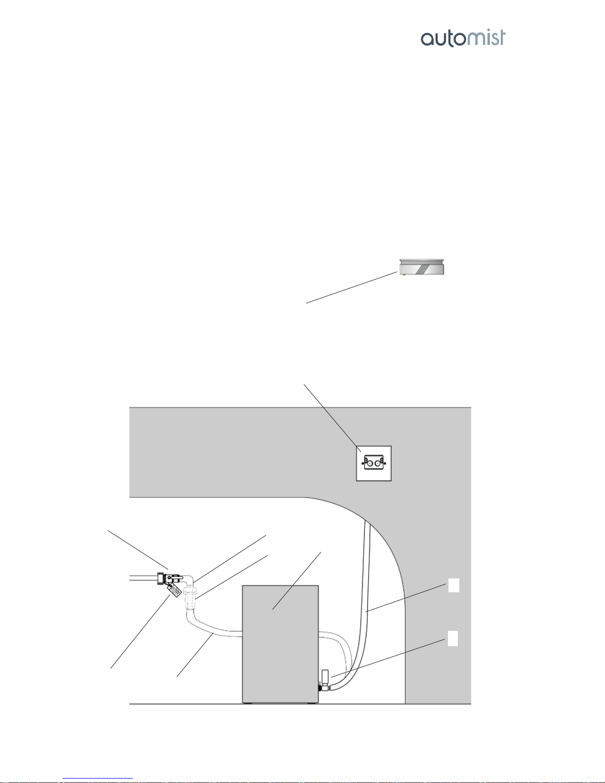
The Automist System
1. WRAS approved isolation valve
2. Automist Smartscan supply label & cable tie
3. ¾” single check valve
4. Filter
5. ¾” Stainless Steel Inlet Hose
6. Automist Smartscan Pump Unit
7. Quick connect with test point for pressure gauge
8. High pressure Outlet Hose
9. Assembled Automist wall mounted head
10. Heat alarm and relay base (not included)
11. Sticker set (not shown)
10
9
1
2
8
6
7
3
4
5

Automist® Fixed Wall Head Handbook v1.2.3
Plumis Ltd Copyright © 2017. All Rights Reserved. Page 8 of 41
®
The nozzle is positioned at a recommended strategic height of 1.4m to 1.5m from the ground to avoid
obstructions by most domestic furniture while still placing mist close to the base of the fire, maximizing
the effectiveness of the very small water flow.
Fire Performance and Regulations Compliance
LABC Registered Detail
Automist is described in an LABC Registered Detail (EW171) for use in open plan layouts in loft converted
houses in England and Wales. The Registered Details scheme allows UK building control officers to approve
a project without a long and detailed investigation.
The full report "Ad-hoc tests on watermist systems utilising the principles of the procedure defined in Draft
BS 8458: 2014: Annex B, Method for Measuring the Capability of a Watermist System to Control a Fire "Room Fire Test for Watermist Systems with Automatic Nozzles" Document Reference 356142" can be
downloaded from the Plumis website.
A copy of the report can be downloaded from the Plumis website.
Fire Engineered Applications
Automist may be used in a variety of applications as part of a fire engineered solution where suppression is
used as a key enabler for means of escape by extending tenable conditions.
A fire engineering assessment has been commissioned by BB7 Fire Engineering to allow fire engineers to
more easily interpret the fire performance of Automist using Fractional Effective Dosage (FED) heat
calculations for the testing carried out on the BS 8458:2015 test protocol. FED Asphyxia for toxic gases did
not need to be measured as the suppression test protocol is an open door ventilated fire where there is no
retention of combustion gases and oxygen can be freely replaced in the test chamber.
A copy of the report can be downloaded from the Plumis website.
EN 60335-1:2002 Household and similar electrical appliances – Safety:
Automist System Clarifications
• The Automist system is a Class I appliance, meaning the system provides additional electric
shock protection in the form of a fully earthed pump enclosure
• The system therefore uses protective impedance because of the earthed enclosure
• The Automist pump unit is a stationary device
• The spray head is a fixed appliance
• The Automist pump unit uses a type Y power supply cord – if the cord is damaged, it can only be
replaced by Plumis (the manufacturer) to avoid a hazard

Automist® Fixed Wall Head Handbook v1.2.3
Plumis Ltd Copyright © 2017. All Rights Reserved. Page 9 of 41
®
Quality Assurance
Concept
• Independently tested - Objectively and extensively tested by Exova Warrington (further details in
Ad-hoc test on watermist systems utilising the principles of the procedure defined in BS 8458:
2015: Annex B)
• All concept proposals are underpinned by British Standard fire engineering justification.
• CE marked – Tested to meet EU consumer safety, health & environmental requirements
• Water Regulatory Advisory Scheme Approved - Automist fire suppression system was examined,
tested and found, when correctly installed, to comply with the requirements of the United Kingdom
Water Byelaws (Certificate number 1102330)
Company
• Third Party Certification by BRE Global have established Plumis Limited have complied with the
Quality Management Systems requirements of ISO 9001:2008 for the design, manufacture and
supply of water mist fire suppression systems.
Installation
• Installation - Automist should be specified, commissioned and signed-off by Plumis or an
Accredited Reseller. Each installer is fully trained to ensure that every project is installed to the very
highest standards, receiving a Plumis Certificate of Approval on successful completion of their
training.

Automist® Fixed Wall Head Handbook v1.2.3
Plumis Ltd Copyright © 2017. All Rights Reserved. Page 10 of 41
®
HOW TO SPECIFY THE FIXED
HEAD AUTOMIST SYSTEM
Automist® Fixed Wall Head Handbook v1.2.3
Plumis Ltd Copyright © 2017. All Rights Reserved. Page 11 of 41
®
Specifying Automist
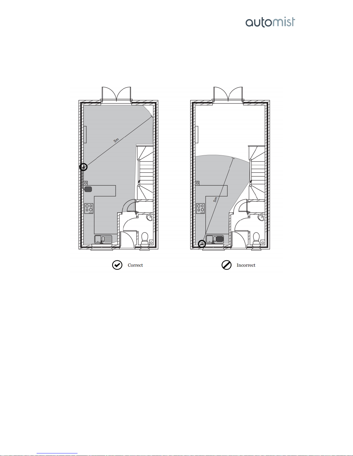
Automist design specification guidelines state that a single pump can cover an area of up to 32m2, with a
maximum ceiling height of 3.5m. Based on third party test data, spray heads must be located within 5m line
of sight of any possible fire location.
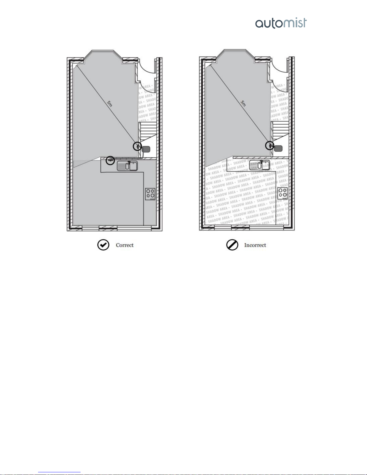
Small potentially blocked or shadowed floor areas shall be permitted on a horizontal plane in
compartments of 64 m2 (two pump units) or less as long as the maximum area of the total contiguous
shadowed floor area, regardless of geometric configuration, does not exceed 2 m2.
Automist® Fixed Wall Head Handbook v1.2.3
Plumis Ltd Copyright © 2017. All Rights Reserved. Page 12 of 41
®
Preliminary Automist designs can be recommended by specifiers by following these recommendations,
however, Plumis accredited installers are trained to specify, install, commission and maintain the Automist
system. Their early involvement in the project is recommended as they are required to verify installation
proposals, provide critical supporting technical information and also commissioning certificates for project
approval by Building Control or other involved third parties.
Automist is accepted for use as a compensatory measure for loft conversions where an open plan
ground floor layout exists. The applicable regulatory guidance is given in paragraph 2.20.b of
Approved Document B (Fire safety) – Volume 1: Dwelling houses (2006 edition incorporating 2010
and 2013amendments). This Registered Detail does not apply to any other Automist product.
For details on the applications where water mist can be used as a means of suppression in BS 9991,
please refer to Appendix B.
Automist® Fixed Wall Head Handbook v1.2.3
Plumis Ltd Copyright © 2017. All Rights Reserved. Page 13 of 41
®
Room Compatibility
A single Automist pump unit was tested by Exova Warrington in an area of up to 32 square metres (2.5m
ceiling height) with fire hazards up to 5m away. The spray head should therefore be within 5m of & in the
approximate line of sight of any fire hazards.
Small potentially blocked or shadowed floor areas shall be permitted on a horizontal plane in
compartments of 64 m2 (two pump units) or less as long as the total area of all individual contiguous
shadowed floor areas, regardless of geometric configuration, does not exceed 2 m2.
The maximum ceiling height must not exceed 3.5m following the guidance on BS 8458:2015. Higher ceiling
applications require the involvement of a fire engineer.
More information on Automist’s appropriateness for a given space is available. Please refer to our technical
area online or contact our technical team.
IMPORTANT: Do not install Automist outside this specification without first discussing the design with
Plumis. Installing Automist outside these guidelines without properly documenting and agreeing such
variations could make you responsible for deaths or injuries.
Installation requirements
• Before installing ensure that the following have been provided at the installation site:
• Sufficient space to install the pump in accordance with these installation instructions. The pump is
365 mm (height) by 240 mm (depth) by 178 mm (width) and weighs 7.0 kg.
• The pump should be installed in one of the following locations with clearance of 100 mm at front
and rear:
• In a room or cupboard with volume of at least 0.124m
3
, that is separated by a fire resisting
partition from the mist-protected room(s) that it serves, or
• In a cupboard with volume of at least 0.124m
3
, within a room that the pump serves, with
the top of the pump less than 80cm above finished floor level.
5m

Automist® Fixed Wall Head Handbook v1.2.3
Plumis Ltd Copyright © 2017. All Rights Reserved. Page 14 of 41
®
• The pump located such that it is: a) unlikely to be affected by a fire b) protected in the
event of fire; c) unlikely to be affected by flooding.
• A 3/4” water supply (connection) with an approved isolation valve located inside the cupboard and
positioned so that the connection point will not be obstructed when the pump is installed.
• A cold water supply which can deliver 6 litres per minute flow at a minimum of 1 bar (100kPa) and
a maximum of 10 bar (1MPa) static pressure. If multiple Automist units are to operate
simultaneously, a proportionately higher flow will be required.
• A dedicated electrical supply circuit in FP200 cable.
• If the consumer unit is located in the same fire resisting compartment as the protected area, it
should be protected by an electrical cover unit tested to BS476 Part 22 (1987) & EN1364-1 (1999).
• Flexible high pressure hoses should be mounted as close to the ground as possible and within the
wall. For cases where the hose is exposed, conduit sleeves must be used. Where the hose is
surface mounted more than 1.2m from the floor in a protected room, or where the hose passes
above/within the ceiling of a protected room, a suitable thermally insulating sleeve may be
required. Never use old hose sets, only use new hoses for each installation. Contact Plumis
technical support for more details.
• Note: When installing flexible high pressure hose behind plasterboard walls, Plumis advises the
hose is left free and unconstrained. This is because mounting the hose in a conduit or narrow
groove within joists makes it more susceptible to perforation when subsequent building works are
carried out.
• Operating ambient temperature: above 4°C.
Spray Head Placement
The Automist Head is designed to be affixed to a standard 50mm deep single-gang mounting box (85mm x
85mm with fixing centres offset centre to centre by 60mm).
IMPORTANT: The Automist head must be located where the spray pattern will not be obstructed and
750mm clearance is provided adjacent to each of the active nozzles. The nozzles must be installed between
1400 - 1500 mm from the ground.
When installing between a work surface and the cupboard, it is better to have the spray head as high as
possible within this space, as long as it 120mm from the lowest point on the cupboard.

Automist® Fixed Wall Head Handbook v1.2.3
Plumis Ltd Copyright © 2017. All Rights Reserved. Page 15 of 41
®
Detection System
Automist’s reliability is dependent on the detection system. Automist is designed to be triggered by a
correctly installed, positioned, and CE marked, heat alarm (BS 5446-2 compliant) or by a heat detector
(EN54-5 compliant) connected to a fire panel3. Automist is activated by feeding its three-wire alarm input
cable from a three-terminal relay that is triggered directly or indirectly by the relevant alarm or detector.
• Automist is designed to be connected to all three terminals of the relay: Common, Normally Open
and Normally Closed. Any wired or wireless fixed-point heat alarm family that offers such a
connection style may be used. A trigger point of 57 degrees (Class 1) is recommended.
• The pump monitors the C/NO/NC connections continuously. In the standby state, the relay must
link the Common and Normally Closed wires together. In a fire state, the relay switches, instead
linking Common to Normally Open.
• Relays with only Common and Normally Open terminals may also be used but in such cases the
Automist pump must be customised by Plumis before shipping.
• DO NOT trigger Automist from a smoke alarm as this will lead to unwanted activations.
• DO NOT connect the Automist pump’s alarm input to any device other than a volt free relay. In
particular, connecting the three coloured cables to the alarm interconnect or to any power supply
whatsoever is likely to damage the Automist pump beyond repair.
• In its default setting, Automist is programmed to run continuously for 30 minutes on activation.
This is designed to prevent interruption of mist even if a heat alarm is damaged by extended
exposure to fire.
• Where multiple Automist units are used, each must take its input from its own dedicated relay
module e.g. the relay base of a heat alarm.
• Where multiple Automist units are used in a single space, the alarm system should activate all relay
units in that space simultaneously. This can be achieved by interconnecting wired heat alarms,
using one alarm relay to drive several additional relays, or associating multiple wireless relay
modules with one or more wireless heat alarms.
3
Other specific alarms/detector models are also acceptable where Plumis has tested the products and
documented their use on the Plumis Partner Site library page, provided that associated Plumis and manufacturer
guidance is followed.
1400 – 1500 mm
Single-gang mounting box

Automist® Fixed Wall Head Handbook v1.2.3
Plumis Ltd Copyright © 2017. All Rights Reserved. Page 16 of 41
®
• Manual call points may be used where the alarm / panel family used supports these and where
they are configured to activate the associated relay.
• Fire alarm panels can add Automist by connection to a relay output provided that this operates
only when the relevant heat detector(s) activate. If desired, SLAVE MODE can be ordered at time of
purchase. This sets Automist to operate only while its alarm input remains active.
• Plumis recommends the use of mains powered heat alarms with back-up batteries since they
significantly increase the reliability of the detection system.
• Ten-year lithium battery alarms are an acceptable alternative when installing a mains-powered
alarm and relay causes unacceptable disruption. Wired lithium battery alarms with an integral
relay are available: correctly configured, these report low battery to the Automist pump and cause
it to go into a “beeping” error state, greatly improving safety: please refer to Plumis’ recommended
alarms documentation on the Plumis Partner Site.
• Wireless ten-year lithium battery alarms are recommended only where a scheduled maintenance
programme is in place. Alarms that use standard replaceable 9V PP3 batteries are not
recommended.
• When using wireless detection, it is not recommended to use complex house coding schemes with
overlapping zones, as installer errors can easily lead to incorrect operation and are hard to track
down.
• Where the relay is not installed adjacent to the pump that it triggers, FP200 or a suitable fire alarm
cable that resists fire for at least 30 minutes must be used for the cable run between the pump
location and the relay.
• Placement of heat detectors / alarms should follow either BS5839-6:2013 section 11.2 (h) to (n) or
BS5839-1:2013 section 22.3. Notably this implies a working range of no more than 5.3m for heat
alarms and gives guidance on unusual ceiling types.
• Automist’s use of heat alarms does not affect or reduce any requirements for the use of smoke
detection in the property. Smoke detection provides a critical independent early warning,
especially with slow-growing fires.
DO NOT install heat alarms:
• Directly over the cooker, stove or oven.
• In areas with high humidity, like bathrooms or shower rooms, or areas to close to dishwashers or
washing machines. Install heat alarms at least 3m away from these areas if possible.
• Adjacent to, or directly above, heaters, air-conditioning vents or ceiling fans.
• In an area where the temperature may fall below 4°C or rise above 37°C.
• Near fluorescent lights. Electrical noise & flickering may affect the operation of the heat alarm.
• Closer than 300mm to light fittings.
• In such a position that it is difficult or dangerous to reach for testing or maintenance or where
children can easily tamper with the alarm.
• In an area where water or other liquids may enter the alarm, except in the extremely unlike case
that the alarm and its connections are waterproof.
• On surfaces subject to significant vibration.
IMPORTANT: Ensure Automist is only connected to the main heat alarm(s) in the volume it protects. You
can check these interconnections using the product’s ALARM TEST MODE (see page 30). In this mode, the
alarm lamp will light to indicate a functioning alarm input. Ensure that Automist has been successfully
returned to the System OK state following this test, and that the water supply remains open, and that
nozzles are unobstructed.
Please refer to BS 5839 for further information on the installation of heat alarms.

Automist® Fixed Wall Head Handbook v1.2.3
Plumis Ltd Copyright © 2017. All Rights Reserved. Page 17 of 41
®
INSTALLER GUIDELINES

Automist® Fixed Wall Head Handbook v1.2.3
Plumis Ltd Copyright © 2017. All Rights Reserved. Page 18 of 41
®
Installation Procedure
A) Preparing the site
B) Configuring the spray head
C) Installing the Automist Head
D) Connecting the water supply
E) Connecting the electrics
F) Commissioning and maintenance
Notice!
Equipment you will need:
• A suitable tool for tightening BSP hoses
• A set of screwdrivers / a suitable electric drill
• Electrical cable
• A pressure gauge kit
• Stud extender or nut wrench
• A commissioning kit (gauge, nozzle tool)
• PTFE plumber’s tape
• A single gang wall mounting electrical box suitable for your wall type

Automist® Fixed Wall Head Handbook v1.2.3
Plumis Ltd Copyright © 2017. All Rights Reserved. Page 19 of 41
®
A) Preparing the site
Important! Connecting the system to the mains requires a competent electrician with 17th Edition
Electrical Qualifications. The Automist circuit should be clearly labelled (a sticker is provided for this
purpose). Automist requires an independent 230V a.c. / 50Hz electrical supply, not shared with other
unrelated devices. Components of the fire detection and alarm system may use this circuit, which must
remain powered in the event of a fire. Power to Automist must be provided via an unswitched fused
connection unit (FCU). Automist should be supplied using FP200 cable or better, ideally inside conduit or
protected 50mm deep within a wall, and with no RCD or RCBO protection. RCD or RCBO protection may be
required, however, by applicable electrical installation regulations, in which case the circuit design must be
such that the operation of any other RCD, RCBO or safety device does not affect the operation of Automist.
Typically, on a split-load board, Automist should be connected to the non-protected side of the board.
Where there are no spare ways in the existing consumer unit, or there are no available non-RCD protected
ways in the existing consumer unit, the electrician may wish to use a Henley Block to provide new tails to a
second distribution board (typically a 2- or 4-way unit).
The Automist unit presents a part-inductive load and therefore only type “C” breakers are suitable. Because
Automist is often used for life safety applications, installers should add a suitable safety margin to the MCB
ratings. The circuit supplying a single Automist unit would commonly be protected by a type ‘C10’ or ‘C16’,
for example, or ‘C20’ / ‘C32’ for two Automist units. This should be on a C-type breaker, on an RCBO or a
RCD protected circuit. The RCD circuit should protect only the Automist system and not be incorporated
with any other circuit in the property. If the consumer unit is located in the protected area it should be
protected by an electrical cover tested to BS476 Part 22 (1987) and EN1364-1 (1999). If the electrical
installation is required to follow BS 8458 DPC, the stipulations of that standard should be adopted; in
particular it requires the use of fuses rather than MCBs and requires a “separately fused connection taken
after the meter and from the supply side of the domestic or residential fuse box”.
13 amp fused unswitched connection
unit located close to the Automist pump’s
location
FP 200 fire resistant cable
Separate
circuit

Automist® Fixed Wall Head Handbook v1.2.3
Plumis Ltd Copyright © 2017. All Rights Reserved. Page 20 of 41
®
Power Loss Alarm
It is possible to fit a power loss alarm to the system, to alert the user if power is cut. Because the alarm is
installed to detect a loss of power, it must be installed on a separate spur of the same circuit as the
Automist system.
Many options for such an alarm are available and Plumis recommends the purchase of an inexpensive
alarm from Amazon, using the following link:
https://www.amazon.co.uk/gp/product/B01GE3NDB4/ref=pd_cp_107_1?ie=UTF8&psc=1&refRID=REA5Y9F0R
C54QWVN72WM
B) Configuring the Spray Head
Only the Plumis technical team, a Fire Engineer or an Accredited Installer/Reseller can specify appropriate
locations and configurations for Automist.
Whilst referring to the layout specification, adjust the nozzle configuration to suit the space. Use the nozzle
adjustment tool provided with the commissioning kit to gently but firmly tighten each nozzle. Nozzle o-rings
are provided to form a good seal at the interface. Silicone grease should be used for lubricating and
preserving o-rings.
The nozzle adjustment tool should be used to fasten the blanking caps in place.
The table below shows the options of jets depending on the layout of the area to be protected:
Layout
Nozzles
4 nozzle spray (4N)
4 x A8
2 nozzle spray (2N)
2 x A16
N.b. The lower the nozzle number, the lower the flow (litres per min)
p
Automist manifold
o-ring
No
Allen key
Nozzle
adjustment
tool

Automist® Fixed Wall Head Handbook v1.2.3
Plumis Ltd Copyright © 2017. All Rights Reserved. Page 21 of 41
®
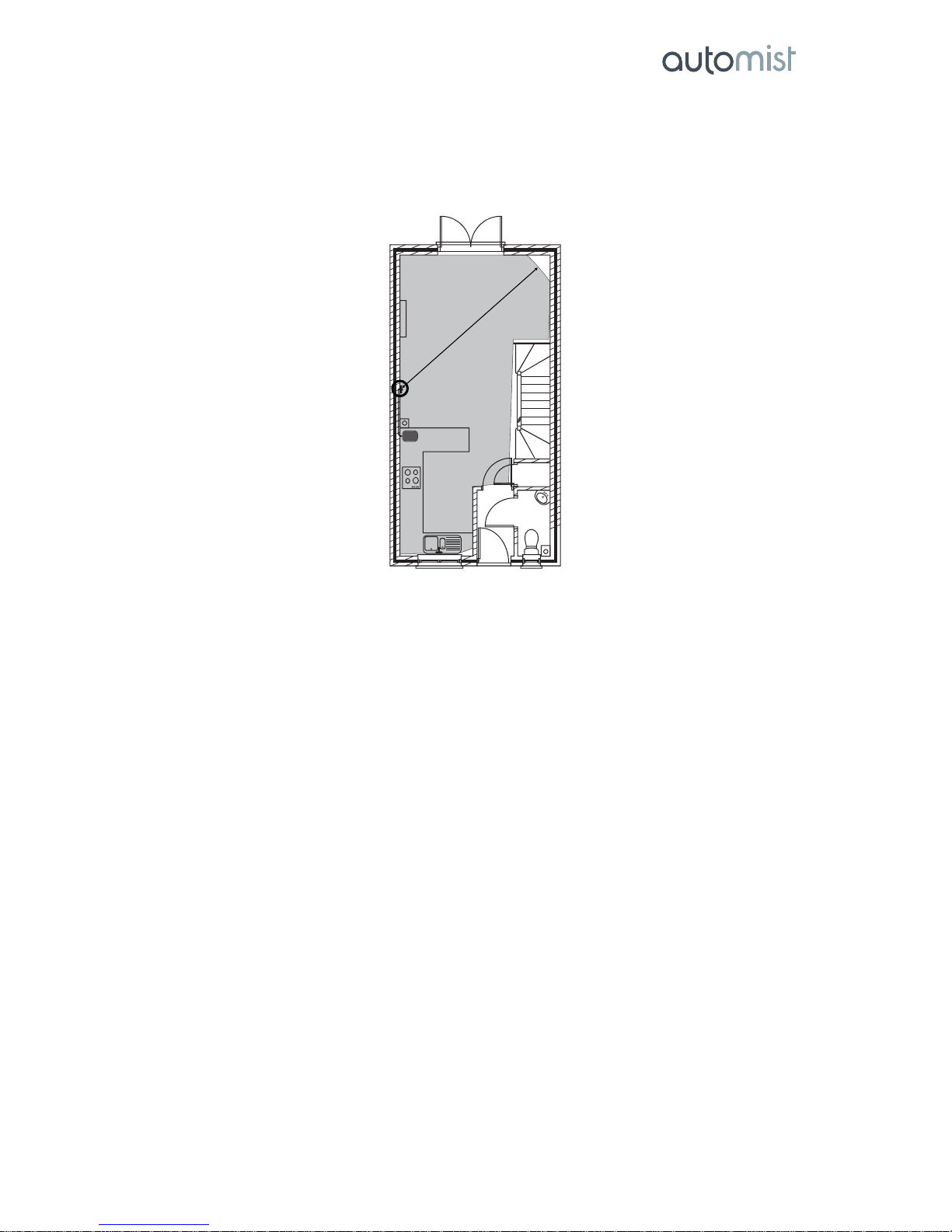
In the narrow kitchen (below) a wall mounted unit is used to protect the space with a 2 spray configuration.
The manifold is set up with 2 x A16 nozzles and 2 blanks.
C) Installing the Automist Head
IMPORTANT: When installing an Automist head with four nozzles you must make sure the active nozzles
are pointing into the room and not towards the wall. PTFE tape should be wrapped approximately three
times around the hosetail thread that enters the spray head.
Assemble the spray head. In the correct orientation the screw is positioned alongside the union.
There will be interference between the male/male union and the head fixing screws. This is expected and
helps to seal the union thread with PTFE to avoid leaks.
Cut a hole in the appropriate location of the mounting box for the high pressure hose. An elbow
connection is included in the kit for use when necessary.
Spray head
Washer
M5 screw
Hose tail
PTFE tape

Automist® Fixed Wall Head Handbook v1.2.3
Plumis Ltd Copyright © 2017. All Rights Reserved. Page 22 of 41
®
IMPORTANT: Make sure the hose is slack enough to allow easy removal of the head for commissioning.
This may require use of a conduit in some wall types.
Single-gang 50mm deep
mounting box
Single-gang 50mm
deep mounting box
High pressure hose
Elbow connection
Minimum clearance
between the back of the
face plate and the high
pressure hose nut
20mm

Automist® Fixed Wall Head Handbook v1.2.3
Plumis Ltd Copyright © 2017. All Rights Reserved. Page 23 of 41
®
D) Connecting the water supply
IMPORTANT: The flow to a fire suppression device must be ensured when using a domestic water
supply. This can be assumed when there is only a single pump connected because of its very low (6
lpm) flow requirement. However, if more than one pump is being linked to work simultaneously in a
fire, a survey needs to be carried out to ensure that there will be water supply available to both the
Automist pumps and the normal domestic supply in its worst condition. Otherwise a priority valve or
a booster pump may need to be used to provide the required flow and pressure. It is responsibility of
the installer to ensure the water supply to the Automist pumps is adequate.
The water supply should comply as follows:
• A check valve must be installed to ensure back flow protection to the mains water (supplied in kit).
• WRAS approved isolation valves (or equivalent) are required so that the Automist Smartscan
system can be shut off from the water main. All such valves should be labelled with the included
warranty void anti-tamper sticker. This enables clear identification of any tampering with the
water valve (note: spare stickers can be ordered from Plumis)
• Priority valves are not normally required but should be used in circumstances where the water
supply may otherwise be inadequate.
Position the pump unit as closely as possible to the mains water supply pipes.
IMPORTANT: If new pipe has been fitted, remember to flush out any contaminants before connecting to
Automist Smartscan, to avoid clogging the nozzle.
Place sticker over valve body &
handle, ensuring both are
connected by the sticker
When valve is disturbed, the
sticker will disintegrate

Automist® Fixed Wall Head Handbook v1.2.3
Plumis Ltd Copyright © 2017. All Rights Reserved. Page 24 of 41
®
The pump should be installed in one of the following locations:
• In a room or cupboard with volume of at least 0.124 m3, that is separated by a fire resisting
partition from the mist-protected room(s) that it serves, or
• In a cupboard with volume of at least 0.124 m3, within a room that the pump serves, with the top
of the pump less than 1m above finished floor level.
IMPORTANT: Leave a 100 mm gap without obstruction at both the front and back of the pump. Do not
cover the pump with any products or materials.
IMPORTANT: If new pipe has been fitted remember to flush out any contaminants before connecting to
Automist, to avoid clogging the nozzles.
Connect the high pressure hose from the assembled head to the outlet on the pump. Plumis supplies
suitable high-pressure hoses. If using another brand of hose, follow Plumis’s guidance note, available on
the Plumis Partner Site. All high pressure hoses should have a minimum working pressure of 150 bar,
minimum internal diameter of 6.3mm and a minimum burst pressure of 600 bar. For hoses longer than 4m,
hoses with a robust rubberised exterior and double wire braiding are recommended such as DIN EN 853
2SN / SAE 100R2AT or DIN EN 857 2SN, rated to 400 bar working pressure and a minimum internal
diameter of 6.3mm. Hoses crimped on-site must be pressure tested to at least 150 bar before the
commissioning procedure to check for correct assembly. High pressure hoses left exposed in the protected
volume, particularly at height, could be compromised in a fire. Hoses should therefore be encased in the
wall whenever possible. Where possible, hoses should be run low in the room, all other factors being equal,
and in any case the locations of hoses must be chosen so that they will not be exposed to temperatures
above 100°C. For hoses longer than 10m and up to 20m, please refer to the high pressure hose technical
specification document on the Partner Site. Longer hoses require an increased internal diameter of 5/16" to
account for the higher pressure drop. IMPORTANT: Plumis’s most recent guidance document on hose
specification is more detailed and overrides this document if there is any ambiguity.
A brass quick connector and locking pin is supplied to connect the high pressure side of the pump to the
spray head. A small o-ring is included. The locking pin retains the quick connector in the pump outlet but
can be easily removed, for example in order to drain water from the high pressure hose. Connect the test
point adaptor between the high pressure hose and the quick connector. The test point adaptor is required
as part of the commissioning procedure (see page 29).
KEEP
CLEAR
KEEP
CLEAR

Automist® Fixed Wall Head Handbook v1.2.3
Plumis Ltd Copyright © 2017. All Rights Reserved. Page 25 of 41
®
The Automist pump unit should be housed close to a 3/4” BSP water supply with an approved isolation
valve to the check valve. A synthetic rubber washer is supplied with each device to facilitate fitting to the
flat-faced outlet. To connect the braided hose apply 6Nm using a calibrated torque wrench, or hand tighten
the hose and then using a conventional wrench, apply another 1/2 turn clockwise to guarantee a reliable
seal.
IMPORTANT! Do not attempt to operate the pump without the quick connector o-ring. Always properly
replace the quick connector, o-ring and locking pin after removal.
IMPORTANT! To comply with water regulations, an approved isolation valve must be used when connecting
the check valve to the mains. A cable tie is provided to tie the Automist supply pipe label to the isolation
valve. The warning label must be visible but must not obstruct isolation valve operation.
¾” BSP water supply
Check valve
Stainlessst
eel hose
Pump ¾”
inlet
Warning
label
Locking pin
o-ring
Quick Connect with
Test Point
Filter

Automist® Fixed Wall Head Handbook v1.2.3
Plumis Ltd Copyright © 2017. All Rights Reserved. Page 26 of 41
®
IMPORTANT! An additional provided filter is required for each installation within the low pressure water
path (mains-water inlet). It can be connected:
• Before the Check Valve OR
• Between the Check Valve and the Flexible Hose OR
• Between the Flexible Hose and the Pump's inlet connector.
Prior to sealing the filter, ensure the washer is lubricated using a suitable silicone-based o-ring lubrication
grease.
Note: If the filter has a paint mark running over the cap and body (as in the image below), then the o-ring
has already been lubricated and the connection adequately made by Plumis.
Only a single spray head can be used with each Automist pump.
IMPORTANT! To enable a consistent pressure and seal for all low pressure water interface washers, the
correct amount of torque should be applied to each low pressure connection. This can be accomplished in
2 ways (with the washers and mating surfaces kept dry):
i) Apply 6Nm using a calibrated torque wrench
OR
i) Hand tighten the hose.
ii) Using a conventional wrench, apply another 1/2 turn clockwise to guarantee a reliable seal.
D) Connecting the electrics
IMPORTANT! The Automist pump should be positioned in a safe and dry location where it is easily
accessible, the button will not be pushed accidentally, and the front panel remains visible when the access
door is open. For installations that require a wireless relay receiver, position the relay base on the wall next
to the Automist pump unit, as close as possible to the front of the cupboard door.
IMPORTANT! Connecting the power requires a suitably qualified & competent person. Switch off electricity
at the mains before working on existing circuits.
IMPORTANT! Follow the detection/relay guidance on page 20.
IMPORTANT! The relay must be set to continuous, not pulse mode, if applicable.

Automist® Fixed Wall Head Handbook v1.2.3
Plumis Ltd Copyright © 2017. All Rights Reserved. Page 27 of 41
®
View of the system upon installation completion (under sink)
Wiring diagram for Automist Pump
In addition to the alarm relay input and the power cables at the rear of the unit, the pump features a single
core loop cable. This is to allow an auxiliary (external) STOP button to be added, for example if the pump is
installed enclosed in a space where the STOP button is inaccessible. Where required, the loop should be cut
and each end of the wire connected via FP200 cable to a momentary action, normally closed, push button
switch (see diagram below).
Pump
Non-switched fused
connection unit
relay base (typical for wireless heat
alarm installations)

Automist® Fixed Wall Head Handbook v1.2.3
Plumis Ltd Copyright © 2017. All Rights Reserved. Page 28 of 41
®
The button should have an appropriate IP rating (e.g. IPX5 if used in the room protected by Automist),
located as close to the pump as possible and should be clearly labelled. The auxiliary button cannot be
used to commission the unit but can be used to enter ALARM TEST MODE (see page 30). Technical notes on
suitable buttons are available from the Plumis Partner Site.

Automist® Fixed Wall Head Handbook v1.2.3
Plumis Ltd Copyright © 2017. All Rights Reserved. Page 29 of 41
®
E) Commissioning and maintenance
IMPORTANT! Commissioning is required:
• Once all the components of the system have been installed and the system is powered.
• As part of a yearly maintenance cycle
• If plumbing or construction work takes places, new alarms are installed or maintenance work
occurs which could affect the system.
• Commissioning must be performed by an Accredited Automist Installer yearly.
When Automist is powered up for the first time the yellow FAULT LED will indicate that the system has not
been commissioned. Commissioning is a simple programmed procedure which allows Automist to be
tested. During commissioning, the pump runs for approximately 20 seconds and the output pressure is
monitored.
When the Automist head is wall mounted, use the wall maintenance tool to prevent mist being sprayed into
the room. Use the standard screws to fasten the tool in place and put a bucket under the hose during the
test procedure.
If you do not have a wall maintenance tool, remove the single-gang plate. Pull the connected spray head
through the hole and place it within a bucket. The manifold should be placed within a plastic bag during the
test procedure. Be careful not to lift the pump or snag the high pressure hose when pulling it through the
hole in the wall. When commissioning two spray heads running off a single pump, two people may be
required (one to securely cover each head).
Place the maintenance tool
over the spray head and
fasten the screws

Automist® Fixed Wall Head Handbook v1.2.3
Plumis Ltd Copyright © 2017. All Rights Reserved. Page 30 of 41
®
The Automist Controls
STOP Button: Pressing the STOP button during a fire condition will stop the Automist pump for 2 minutes. If at the
end of 2 minutes, an alarm input remains active, Automist will recommence mist operation. If the alarm condition
has ended, Automist will return to stand-by.
In error conditions, pressing the STOP button temporarily hushes the error sounds.
In the SYSTEM OK stand-by, the STOP button may be used to enter ALARM TEST MODE. In this mode you have a
short time to test alarms in the home without activating Automist.
ALARM LED: Lit red to indicate an ALARM condition.
FAULT LED: Lit yellow to indicate a fault. Please refer to the troubleshooting guide. N.B. When Automist is powered
up for the first time the yellow FAULT LED will be lit to indicate the system has not been commissioned
SYSTEM OK LED: Lit green when the system is OK and on stand-by.
IMPORTANT! Automist should never be left in a fault condition. Error LEDs indicate that the system
requires attention and may not operate in the event of an alarm.
Commissioning Procedure
1. Unscrew the cap and connect the test hose and gauge to the test point adapter. Place the test
shield around the tap mount spray head, or place the wall mount spray head behind the
maintenance tool or within a plastic bag
2. Press and hold the STOP button for more than 5 seconds. A long beep followed by four short
beeps indicate that you may release the button. This COMMISSIONING MODE is indicated by
four short beeps every 5 seconds accompanied by four short flashes of the ALARM LED. If an
alarm input is not received within 1 minute, Automist will revert to stand-by.
3. Test the heat alarm / fire panel output as recommended in its user manual. Keep the alarm
output on for more than 15 seconds). N.B. Some heat alarms take up to 10 seconds to
trigger their alarm relays: the alarm may have to be kept sounding for this period to activate
Automist.

Automist® Fixed Wall Head Handbook v1.2.3
Plumis Ltd Copyright © 2017. All Rights Reserved. Page 31 of 41
®
4. Check the gauge and ensure that the output pressure reaches a stable 75 to 100 bar. You may
have to run the pump continuously for 30 seconds prior to commissioning to remove trapped
air in the line.
IMPORTANT! The pump features a cut-out which will disable it if the pressure becomes
excessive, so it is critically important not to leave an installed system with a high out-of-spec
pressure. By leaving an installed system with pressures outside the specified range, you might
become liable for deaths or injuries. If the achieved output pressure is outside the specified
range, refer to the commissioning troubleshooting guide (see page6) and contact Plumis on
020 7871 3899 if the situation cannot be resolved.
5. Make sure you replace the mist head with the active nozzles pointing into the centre of the room.
Slight dripping from the head assembly itself may occur during testing. This need not be
addressed but may be remedied with silicone sealant under the head if desired.
6. Once you have successfully commissioned your unit, complete the online commissioning form
and attach a layout diagram.
7. Place the two warning stickers and the commissioning label:
• Label the separate circuit on the circuit breaker
• Label the heat alarm that triggers Automist, preferably near the test button
• Complete the installer commissioning label and affix to your Automist unit
• Complete the user manual with the relevant information for the occupier
IMPORTANT! Record the output pressure from the commissioning gauge on the Installer Label (as shown
below) and keep a note of the details for the online commissioning form.
75
100

Automist® Fixed Wall Head Handbook v1.2.3
Plumis Ltd Copyright © 2017. All Rights Reserved. Page 32 of 41
®
8. Carefully remove the test hose and gauge and re-attach the cap on the test point adapter.
9. Following a successful pressure test, the high pressure hose must be cleared of water by
connecting a suitable pump to the Plumis supplied attachment, that is connected to the test
point tee.
10. Verify that any wireless detection is correctly set up. If you used wireless Aico detection:
a. Use a battery powered Aico detector in factory mode or the Aico tester key fob (again in

Automist® Fixed Wall Head Handbook v1.2.3
Plumis Ltd Copyright © 2017. All Rights Reserved. Page 33 of 41
®
factory mode), to see whether either will set your system off. Use ALARM TEST MODE which
mutes the pump while doing any connectivity tests. If the ALARM lamp lights when you
sound any given detector for a few seconds, that means that the Pump will activate when
that alarm goes off. This should only happen for the specific heat detectors linked to
Automist.
Complete the user manual / information sheet with a permanent pen.
Post-installation checklist – Key points for installers and Building
Control
Power supply
• The Automist circuit should be clearly labelled (a sticker is provided for this purpose).
• Power to Automist must be provided via an unswitched fused connection unit (FCU).
• Automist should be supplied using FP200 cable or better, ideally inside conduit or protected 50mm
deep within a wall
• Automist may be protected by an RCD or RCBO but this protection must not be shared with other
circuits. Therefore Automist should be connected to the non-protected side of the consumer unit.
• The circuit supplying a single Automist unit would commonly be protected by a type ‘C10’ or ‘C16’, for
example, or ‘C20’ / ‘C32’ for two Automist units.
• If the consumer unit is located in the same fire resisting compartment as the protected area, it should
be protected by an electrical cover unit tested to BS476 Part 22 (1987) & EN1364-1 (1999).
Water Supply
• check valve and filter must be installed to protect the mains water supply from back flow and the pump
from debris (supplied in kit).
• Inlet water must be connected and the valve left open.
• WRAS approved isolation valves (or equivalent) are required so that the Automist system can be shut
off from the water main. All such valves should be labelled with the included supply warning labels.
• Priority valves are not normally required but should be used in circumstances where the water supply
may otherwise be inadequate.
• Several pumps can be supplied from the same 15mm water pipe as long as they are not intended to
activate at the same time. Larger diameter piping may be required for simultaneous activation of more
than a single pump.
Pump & Placement
• All Automist units should have been successfully commissioned using heat detectors, with outlet
pressure verified.
• Minimum ventilation / cupboard size requirements met (124 litres).
• In a room or cupboard that is separated by a fire resisting partition from the mist-protected room(s)
that it serves, or the pump located such that it is: a) unlikely to be affected by a fire, b) protected in the
event of fire; c) unlikely to be affected by flooding.
• Each Automist pump should show “System OK” (green LED), indicating it has been successfully
commissioned.

Automist® Fixed Wall Head Handbook v1.2.3
Plumis Ltd Copyright © 2017. All Rights Reserved. Page 34 of 41
®
Alarm Relay Placement
• Each Automist unit should be activated by its own separate relay device.
4
• Each relay must be located so that it is a) unlikely to be affected by a fire; b) protected in the event of
fire; c) unlikely to be affected by flooding or by dripping/splashing water; d) unlikely to be subject to
unusual vibration.
• Any potential house coding problems or fire panel cause-and-effect issues should be checked by
entering ALARM TEST MODE on all pumps and sounding both related and unrelated detectors.
Head Placement
• Between 1.2 and 1.4m high for Smartscan, between 1.4m and 1.5m for fixed head.
• In a “preferred position” where it is not susceptible to furniture obstruction
• Head placement matches the layout drawing supplied with the commissioning form.
High Pressure Hose
• High pressure hose should have been flushed with air to remove water, avoid dripping and Legionella.
• High pressure hose should be protected by a fire resisting barrier.
• It is critically important that the high pressure hose locking pin (behind the pump) is in position so that
the quick connector and o-ring are firmly retained after any operations that required disconnection of
the high pressure line.
Coverage
• If protecting the means of escape only, ensure all adjacent rooms which are not separated by a fire
resisting door are covered. Covering only the stairs will not suppress fires in non-separated adjacent
rooms, negatively impacting tenability on the escape route.
Documentation
• Installer sign-off details (including pump pressure) are noted on pump
• An occupant information sheet should have been provided to the property
• The Installer Commissioning form should have been provided (can be obtained from Plumis or the
installer) with a matching layout drawing
The Plumis Warranty Certificate is provided (can be obtained from Plumis) once the layout has been
submitted and approved by Plumis.
4
Single throw relays must not be shared between multiple pumps. Each pump must have a separate relay, or
where a multi-throw relay has been used, each pump must have a separate “throw”.

Automist® Fixed Wall Head Handbook v1.2.3
Plumis Ltd Copyright © 2017. All Rights Reserved. Page 35 of 41
®
FIXED HEAD SYSTEM CARE

Automist® Fixed Wall Head Handbook v1.2.3
Plumis Ltd Copyright © 2017. All Rights Reserved. Page 36 of 41
®
Cleaning
The Automist wall-mounted head should be wiped clean with a damp cloth. Do not attempt to clean with
any other chemical cleaners or abrasives
Repair
CAUTION! Do not attempt to repair the Automist wall head or pump unit. Doing so will invalidate your
warranty.
Automist should be serviced or replaced if it has been if any part of the system, including any heat alarms,
have been exposed to fire conditions.
Troubleshooting
Problem
Probable Cause
Recommended Action
Pressure does
not consistently
reach correct
range (too low)
during
commissioning
procedure
Leakage between
pump and Automist
head
Check for leakage on the high pressure water path, for
example the quick-fit connector may not be secured or its
o-ring may not have been fitted.
Re-run commissioning.
Blockage at the pump
inlet
Close off the water with the isolation valve.
Disconnect the hose at the pump inlet and check for
blockages on the pump strainer and within the inlet hose.
Incorrect Nozzle
specification
Check to see the correct specified nozzles have been
installed (nozzle “A” numbers should sum to 32 on each
pump, where present).
Please contact your Automist supplier.
Mains pressure or
flow is too low
Close off the water with the isolation valve and disconnect
the hose.
Verify that the water mains connection can supply at least 6
litres per minute (lpm) of flow and if possible check that the
static inlet pressure is at least 1 bar.
If the flow is close to or below 6 lpm, the mains pressure
may be too low for Automist to operate correctly, or there
may be constrictions in the water supply. A plumber should
be called to resolve the issue.

Automist® Fixed Wall Head Handbook v1.2.3
Plumis Ltd Copyright © 2017. All Rights Reserved. Page 37 of 41
®
Pump not providing
enough flow
Re-run the commissioning procedure with the high
pressure hose outlet placed inside a container with volume
markings.
If the volume of water is less than 1.6 litres, there may be
an inadequate water supply or a damaged pump. Please
contact Plumis technical support.
Pump
persistently
produces a
warbling sound
and shows
FAULT lamp
Pump not yet
commissioned
Incorrect wiring to
pump or spray head
Pump or spray head
damaged in transit
The number of beeps (or trills) that the pump sounds when
in fault mode is intended as a diagnostic. Please count the
beeps:
two beeps is the normal state of the decommissioned
pump
three beeps – wiring fault: check that you have correctly
wired exactly one pump to exactly one relay (see page 26)
and that the pump’s external stop loop cable has not been
broken (p26 onwards). If an external STOP button is in use,
check that this provides a normally closed connection.
four beeps indicates that the STOP button is stuck. This
fault is very rare and requires a replacement pump.
Pump does not
run during
commissioning
although there
is power to
Automist unit
Trigger alarm not
connected to Automist
Relay not functioning
or incorrectly wired
Pump damaged in
transit
Check that you have not attempted to connect more than
one pump to a single relay.
Verify that alarm is connected properly by shielding the
spray head, powering the pump off and on and sounding
an associated alarm for at least 10-15 seconds. Automist
should be triggered. Once activated, cancel the alarm
condition by pressing STOP on the pump.
If Automist is not triggered, power off the system and
replace the relay with a two-way a.c. light switch. The NO
and NC terminals on the switch will normally be labelled L1
and L2 (both L1 and L2 terminals must be present and
connected). The pump may immediately start when power
is restored: if so, switch the switch, power off and try again.
Try to commission the pump using the switch in lieu of a
detector’s test button. If you can commission the pump
using a light switch instead of a relay, the fault is with the
relay or relay wiring.
Power circuit
trips out as
soon as pump
starts
Too-small MCB used
for Automist circuit
Please refer to page 19.

Automist® Fixed Wall Head Handbook v1.2.3
Plumis Ltd Copyright © 2017. All Rights Reserved. Page 38 of 41
®
No mist is
produced,
although pump
runs during
commissioning
test
Loose high pressure
hose, leakage
between pump and
Automist head
Water supply is
interrupted
Check for gross leakage on the high pressure water path,
for example the quick-fit connector may not be secured or
its o-ring may not have been fitted.
Re-run commissioning.
Verify that the isolation valve is open and that there is a
water supply to Automist.
Severe blockage at the
pump inlet
Close off the water with the isolation valve.
Disconnect the inlet hose and check for blockages on the
pump strainer and within the hose.
Pump damaged in
transit
Disconnect the high pressure hose from the Automist head
and re-run the commissioning procedure with the high
pressure hose outlet placed inside a container with volume
markings. If volume of water is less than 1.6 litres, the
pump is not providing the correct flow. Please contact
Plumis technical support.
Pump pulses or
stutters during
commissioning
test
Incorrect Nozzle
specification
Check to see the correct specified nozzles have been
installed (nozzle “A” numbers should sum to 32 on each
pump, where present).
Please contact your Automist supplier.
Pump malfunction
Disconnect the high pressure hose from the Automist head.
Re-run the commissioning procedure with the high
pressure hose outlet placed inside a container with volume
markings.
If volume of water is less than 1.6 litres, the pump is not
providing adequate pressure. Please contact Plumis
technical support.
Manifold Blocked
Please contact Plumis technical support.
High pressure hose
blocked
Disconnect high pressure hose between the Automist head
and the pump
Check whether the hose is blocked.
If hose is blocked, call Plumis technical support.

Automist® Fixed Wall Head Handbook v1.2.3
Plumis Ltd Copyright © 2017. All Rights Reserved. Page 39 of 41
®
Warranty
Plumis Ltd warrants its products to be free from defects in materials and workmanship under normal
residential use for a period of two years from the date of original purchase. This warranty is limited to
repair or replacement of units returned to Plumis Ltd according to our return procedure. The warranty on
any replacement units, will last for the remainder of the period of the original warranty. Plumis Ltd reserves
the right to offer an alternative product similar to that being replaced if the original model is no longer
available or in stock.
If the product is found to have failed for reasons outside our warranty cover Plumis may quote to repair the
unit and return it. Where products are replaced or repaired under warranty, they will be returned to a UK
address free of charge.
This warranty does not cover the removal or reinstallation of products, or faults in installation.
Plumis Ltd shall not be liable for any incidental or consequential damages caused by the breach of any
expressed or implied warranty. Except to the extent prohibited by applicable law, any implied warranty of
merchantability or fitness for a particular purpose is limited in duration for two years. This warranty does
not affect your statutory rights.
Notes

Automist® Fixed Wall Head Handbook v1.2.3
Plumis Ltd Copyright © 2017. All Rights Reserved. Page 40 of 41
®
FIXED HEAD SYSTEM SERVICING

Automist® Fixed Wall Head Handbook v1.2.3
Plumis Ltd Copyright © 2017. All Rights Reserved. Page 41 of 41
®
Servicing Fixed Automist System
1. Make sure the height of the head is between 1400-1500mm and is not been obstructed.
2. First open the nozzles and check for any blockages
3. Check at the back of the head and make sure that PTFE is between the head and the straight
connector.
4. Check that the 90-degree bend has been used and hoses are not kinked.
5. Visually (when possible) check the high pressure hose for damages or tears have developed.
6. Make sure the house coding or the wiring of the Heat Detector is correct
7. Make sure the power cable and the breaker is sufficient for the number of pumps and head
detectors (if the head detectors are hard wired).
8. If the nozzles are blocked clean them (or replace them) and commission the system without the
nozzles so the high pressure hoses can be flushed of any debris.
9. Insert the nozzles and commission the system
10. Check the pressure/ Record the new pressure (75-100 bar)
11. Check for leaks.
 Loading...