

Page 1

Plug-In Solar Installation Instructions
Sheet Metal/Flat Roof Mount Kit
Plug-In Solar – Power Your Future
www.pluginsolar.co.uk
These installation instructions contain important information on safety matters and the installation
of the Plug-In Solar kit. Please read this guide carefully to ensure safe installation and operation.
*Installations are undertaken at the customer’s own risk. This Installation manual is to be used as a guide only, and your discretion
must be used when installing the Plug-In Solar kit. You MUST follow the IET Wiring Regulations and consult a professional
electrician if you are in any doubt on how to install the system. Plug-In Solar takes no responsibility for incorrect installation of our
kits.
Page 2

Plug-In Solar
289 London Road | Burgess Hill | West Sussex | RH15 9QU
www.pluginsolar.co.uk | [email protected] | 01444 672005
Page 2
TABLE OF CONTENTS
Tool Requirements
3
Component Guide
4
Safety Instructions
5
Warnings
6
Step by Step Plug-In Solar Installation Guide
Metal Roof Mount Installation
7
Micro-Inverter Installation
10
Wiring The Solar To The Existing Mains Circuit
14
Isolation/Isolator Requirements
16
Placing Warning Labels
17
Inspecting, Testing and Commissioning
Inspecting and Testing your Plug-In Solar Installation
18
Commissioning your Plug-In Solar Installation
19
Completing your Warranty Card
21
Appendix
Appendix 1. Plug-In Solar Connection Unit – Wiring Diagram
22
Appendix 2. Example G83/2 SSEG Installation Commissioning Confirmation Form
23
Appendix 3. Example Electrical Schematic Diagram
24
Appendix 4. Troubleshooting APS Dual Micro-Inverters
25
Appendix 5. APS Warranty Document
26
Appendix 6. APS Warranty Card
29
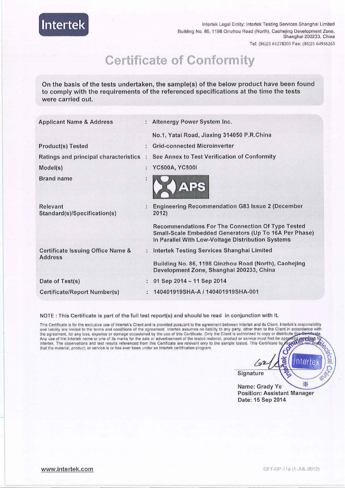
Appendix 7. APS G83/2 SSEG Test Report Certificate
30
Appendix 8. Solar Panel Warranty Document
31
Appendix 9. Solar Panel MCS Certificate
35
Appendix 10. Roof Mount Warranty
37
Page 3
Plug-In Solar
289 London Road | Burgess Hill | West Sussex | RH15 9QU
www.pluginsolar.co.uk | [email protected] | 01444 672005
Page 3
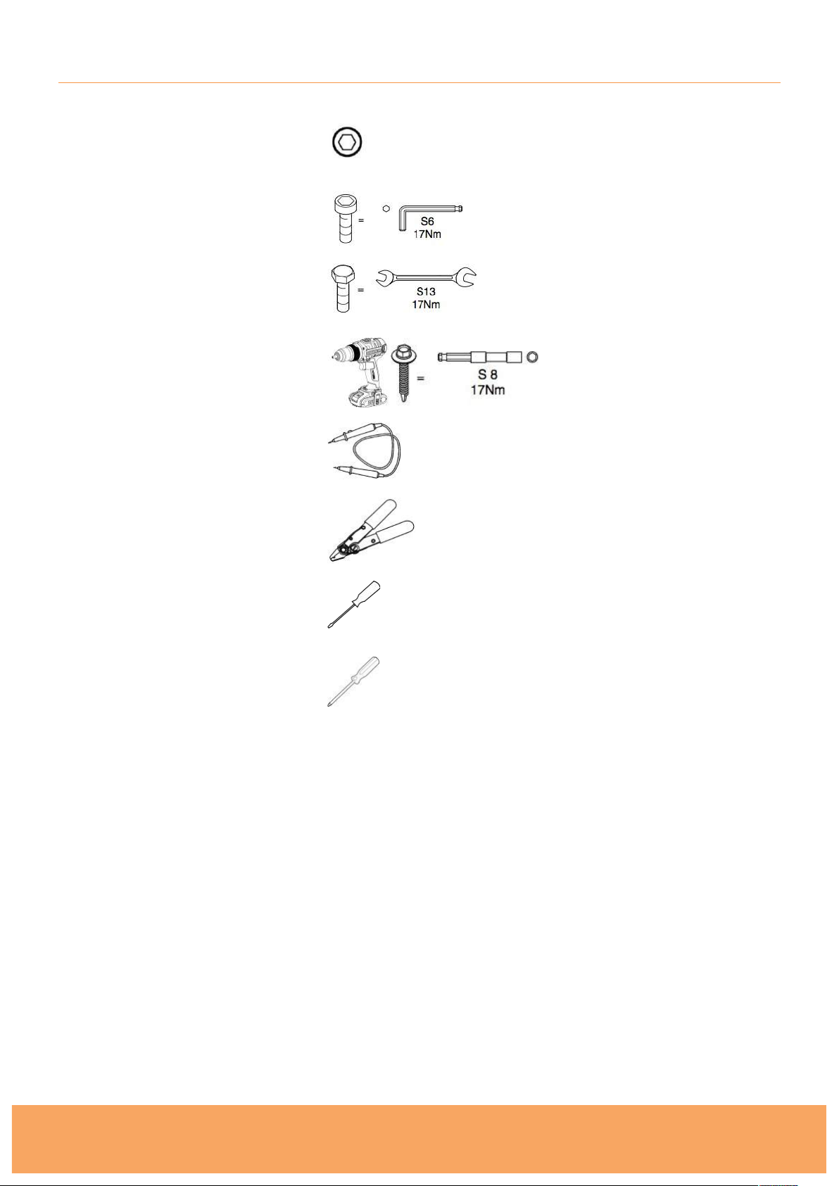
TOOL REQUIREMENTS
8mm Socket Tool
6mm Hex (Allen) Key
13mm Spanner
Drill with S8 Masonry Bit
Voltage Tester
Wire Strippers
Flathead Screwdriver
Phillips Screwdriver
Page 4
Plug-In Solar
289 London Road | Burgess Hill | West Sussex | RH15 9QU
www.pluginsolar.co.uk | [email protected] | 01444 672005
Page 4
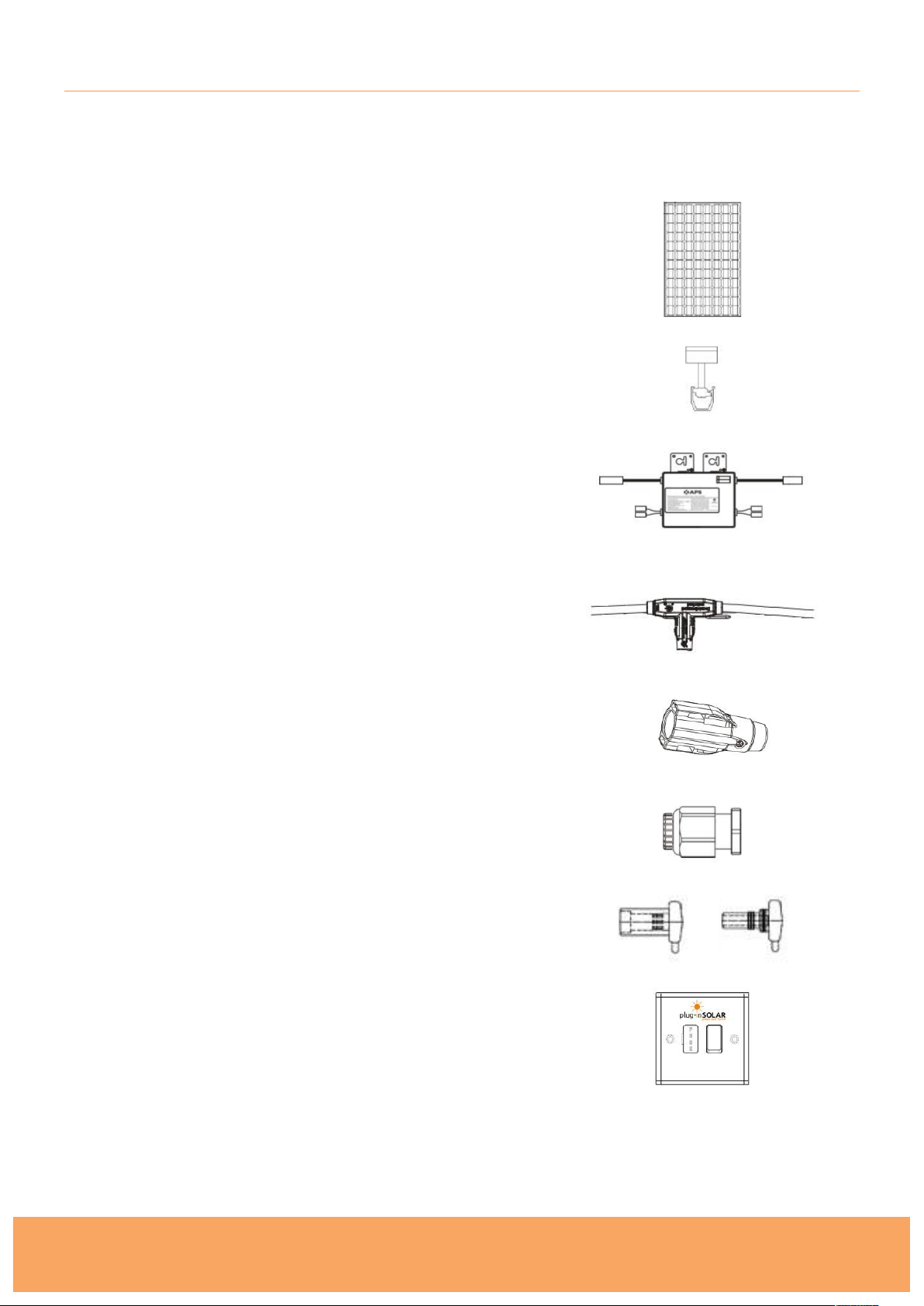
COMPONENT GUIDE
The number of components you receive will depend on the type of kit you have purchased. Please
unpack all your items, and check you have all the correct components based on your Dispatch Note.
Solar Panel
Metal Roof Mounting System
Micro Inverter (Dual Input)
AC Bus (Trunk) Cable
Trunk Cable Sealing Cap
End Cap
MC4 Sealing Caps (for kits with odd number of Solar Panels)
Plug-In Solar Connection Unit
Page 5

Plug-In Solar
289 London Road | Burgess Hill | West Sussex | RH15 9QU
www.pluginsolar.co.uk | [email protected] | 01444 672005
Page 5
SAFETY INSTRUCTIONS
Before installing or using a Plug-In Solar kit, please read all instructions and cautionary markings in
this document and on the Micro-Inverters and Solar Panels.
The installation of a Plug-In Solar kit shall be carried out by a competent person with sufficient skills
and training to apply safe methods of work, in compliance with G83/2 Engineering
Recommendations.
The installation of a Plug-In Solar kit will be carried out to no lower a standard than that required in
the Manufacturer’s installation instructions, as provided here.
No parameter relating to the electrical connection and subject to type verification certification will
be modified unless previously agreed in writing between the DNO (Distribution Network Operator)
and the Customer.
All electrical installations shall be performed in accordance with local electrical codes.
All appropriate health and safety regulations must be observed and required safety precautions
taken.
Be aware that installation of this equipment includes the risk of electric shock.
Be aware that the body of the Micro-Inverter is the heat sink and can reach a temperature of 80°C.
To reduce risk of burns, do not touch the body of the Micro-Inverter.
DO NOT disconnect the PV module from the Micro-Inverter without first disconnecting the AC
power. !In no circumstances, connect a DC input when an AC connector is unplugged.
DO NOT attempt to repair a Micro-Inverter. If it fails, contact APS Customer Support to obtain an
RMA number and start the replacement process. Damaging or opening a Micro-Inverter will void
the warranty.
CAUTION! !The external protective earthing conductor is connected to the micro-inverter
protective earthing terminal via an AC connector. !When connecting; connect the AC connectors
first to ensure the micro-inverter earthing then undertake the DC connections. When
disconnecting; disconnect the AC by opening the branch circuit breaker. Whilst maintaining the
protective earthing conductor in the branch circuit breaker, connect to the micro-inverter, then
disconnect the DC inputs. !
You MUST follow the IET Wiring Regulations at all times and consult a professional
electrician if you are in any doubt.
Page 6

Plug-In Solar
289 London Road | Burgess Hill | West Sussex | RH15 9QU
www.pluginsolar.co.uk | [email protected] | 01444 672005
Page 6
WARNINGS
Never disconnect the DC wire connectors under load. Ensure that no current is
flowing in the DC wires prior to disconnecting. An opaque covering may be used to
cover the module prior to disconnecting the module.
Do not touch any live parts in the system, including the Solar array, when the
system has been connected to the electrical grid.
Prior to installing any of the Micro- I nverters, verify that the utility voltage at the
point of common connection matches the voltage rating on Micro-Inverter label.
Do not mount the Micro-Inverter in a location that allows exposure to direct
sunlight. Allow a minimum of 3/4’’(1.5cm.) between the roof and the bottom of the
Micro-Inverter to allow proper airflow.
Always disconnect AC power before disconnecting the PV module wires from the
Micro-Inverter. The AC connector of the first Micro- Inverter in a branch circuit is
suitable, as a disconnecting means, once the AC branch circuit breaker in the load
center has been opened.
The Micro- Inverter is powered by PV module DC power. Make sure you disconnect
and reconnect the DC connections to watch for the three short flashes.
Page 7
Plug-In Solar
289 London Road | Burgess Hill | West Sussex | RH15 9QU
www.pluginsolar.co.uk | [email protected] | 01444 672005
Page 7
METAL ROOF MOUNT SYSTEM INSTALLATION
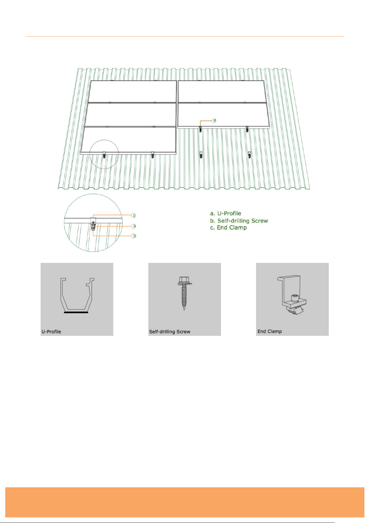
Roof Mounting System Components
1. Before fitting the roof mounting system, please check that:
a) The roof structure is !able to support the Solar Panel array
b) The installation is able to take the wind loadings based on your location
c) You comply with all building codes, including any that may supersede this manual.
d) You maintain the waterproof integrity of the roof.
The roof mount system, when installed in accordance with this guide will be structurally adequate
and will meet the DIN 1055 standards. When installing this product please observe the appropriate
health and safety regulations and take required safety precautions.
Plug-In Solar takes no responsibility for the method by which you choose to install your mounting
system. This is a guide only. Please consult a roofing expert if you are in any doubt on how to
safely and correctly install your system. It is your responsibility to ensure the roof is watertight.
Page 8
Plug-In Solar
289 London Road | Burgess Hill | West Sussex | RH15 9QU
www.pluginsolar.co.uk | [email protected] | 01444 672005
Page 8
Installing the Roof Mounting System
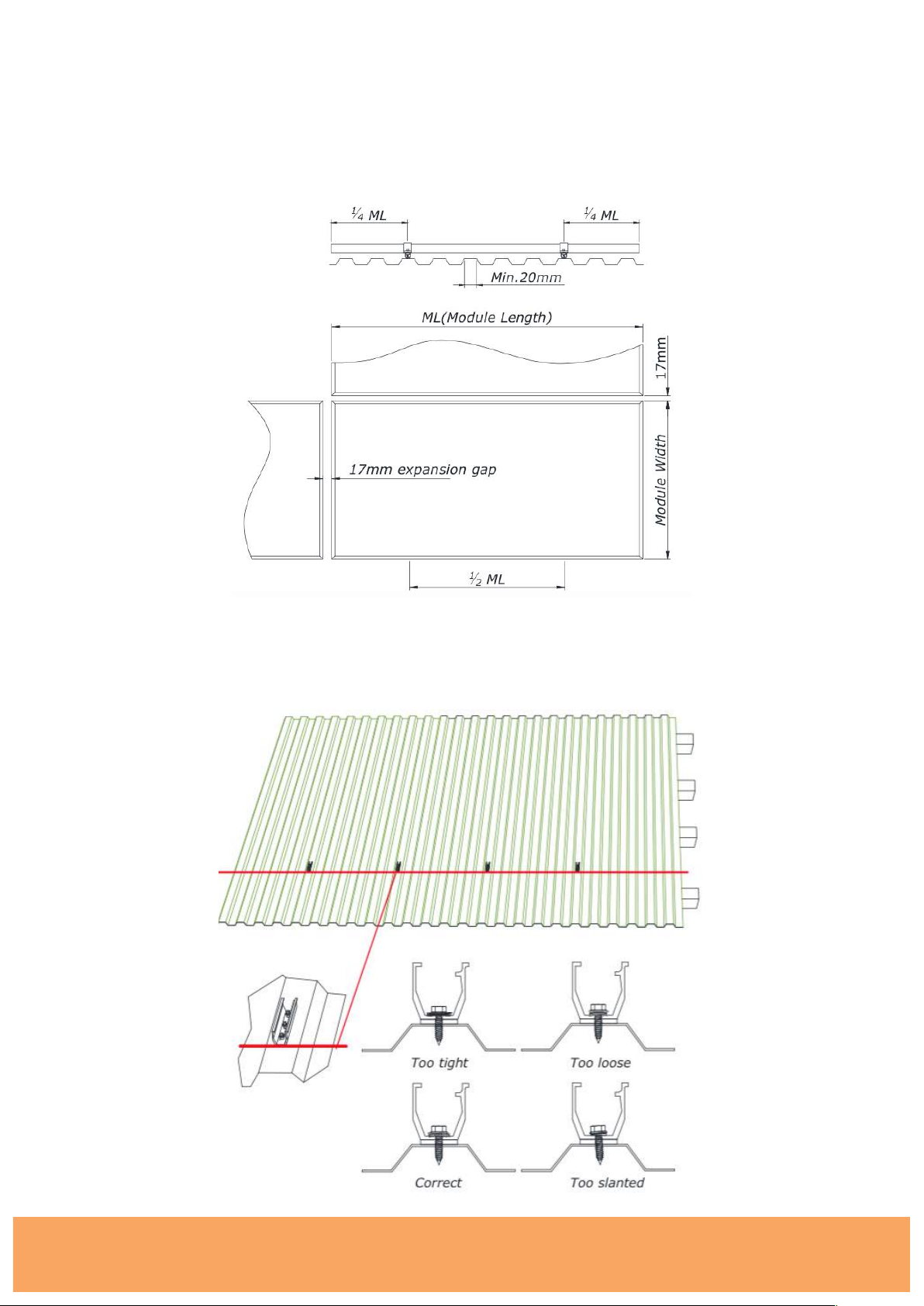
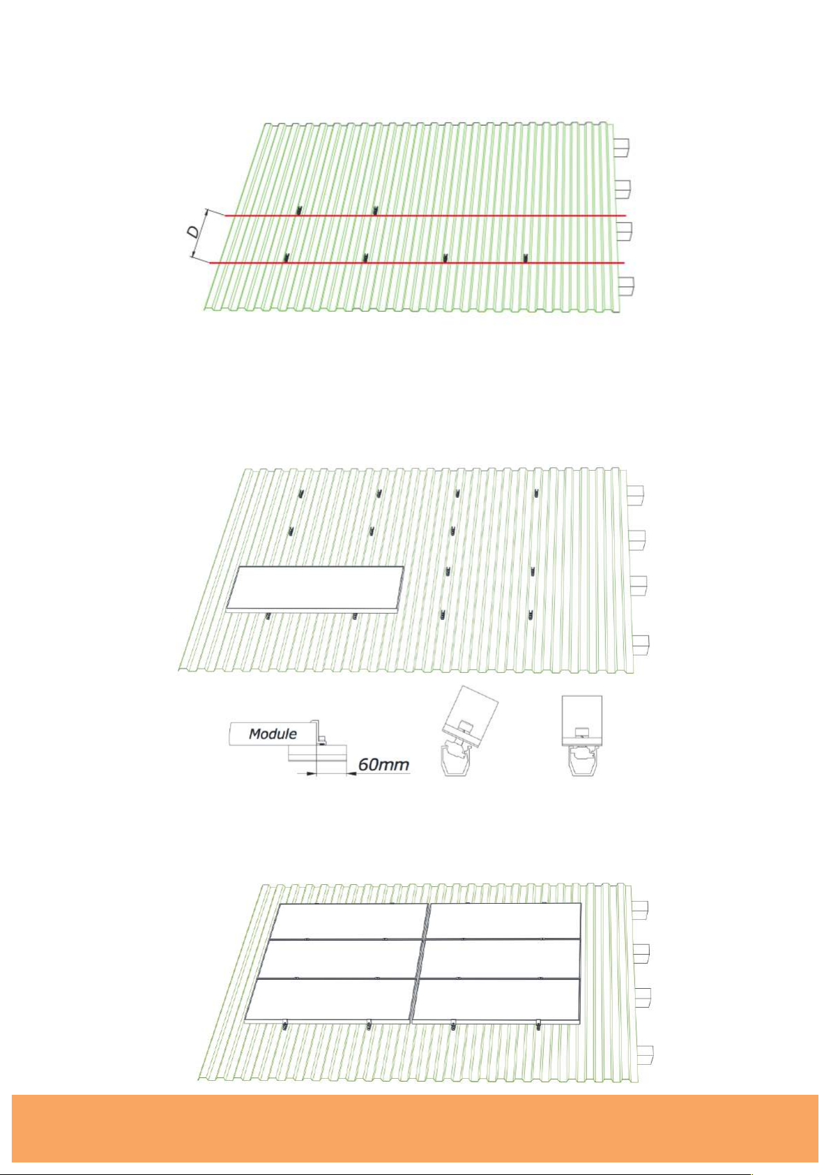
2. The distance between the two U-Profiles will depend upon the trapezoidal sheet profile but
should be as near as possible half the Solar Panel length apart. On the short side of the module
always leave an expansion gap, ideally 17mm.
3. Start on the lower elevation of the roof, ensuring your U-Profiles are in the same line. Use a
marker pen to indicate the correct location of each U-Profile. You will need your 8mm socket
set. Please make sure the screws are tightened correctly.
Page 9
Plug-In Solar
289 London Road | Burgess Hill | West Sussex | RH15 9QU
www.pluginsolar.co.uk | [email protected] | 01444 672005
Page 9
4. Mount the second row of U-Profiles. The distance between the two rows will be:
D= Module width + 18 mm. Continue to mount the rest of the U-Profiles in the same way.
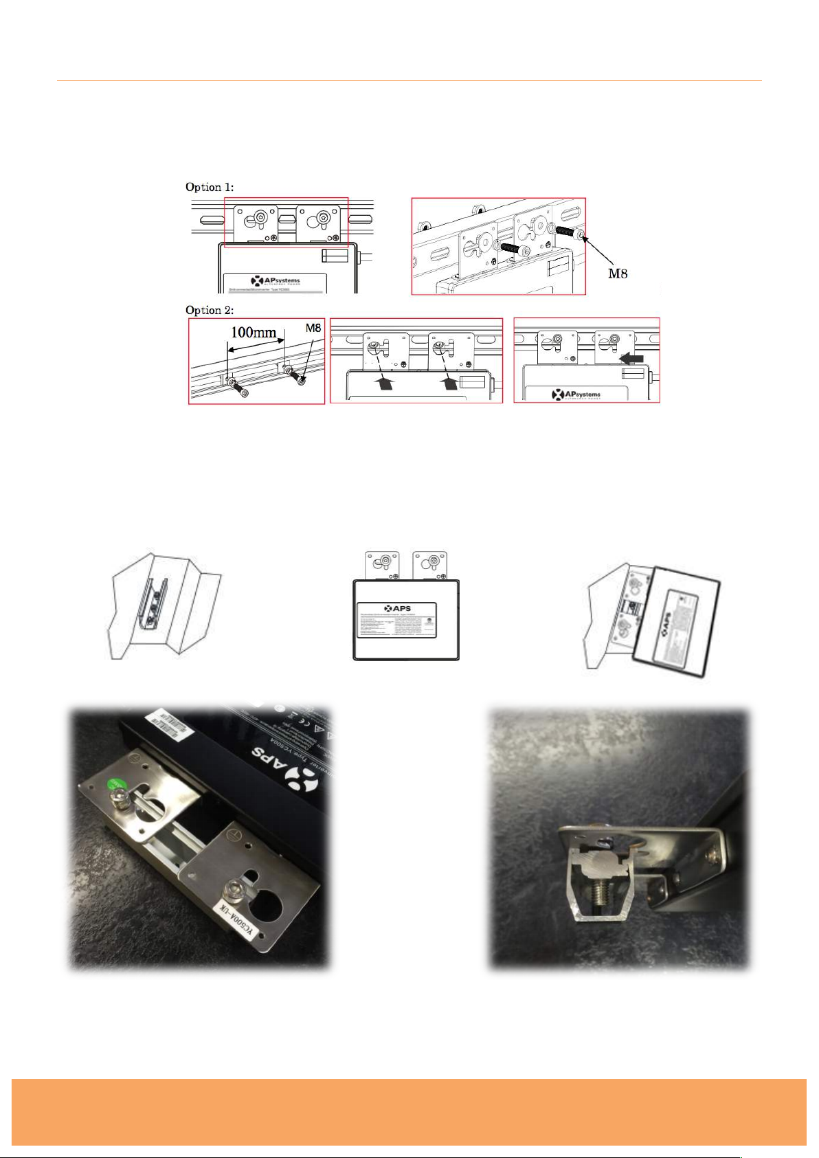
5. Mount the solar panels starting on the lower elevation of the roof. Locate the panels
according!to step 1 at the 1/4 points of the modules. Next attach the end clamps to the Uprofiles as you work along the first row, and tighten the clamps with a 6mm allen key. The solar
panels must be placed in the middle of the U-Profile as the diagram below shows. The
recommended torque to the screws of the clamps: 20 Nm.
6. Continue this process until you have installed all the solar panels. Ensure all screws and
clamps are sufficiently tightened, and your mains cable is accessible for wiring to the mains.
Page 10
Plug-In Solar
289 London Road | Burgess Hill | West Sussex | RH15 9QU
www.pluginsolar.co.uk | [email protected] | 01444 672005
Page 10
MICRO-INVERTER INSTALLATION
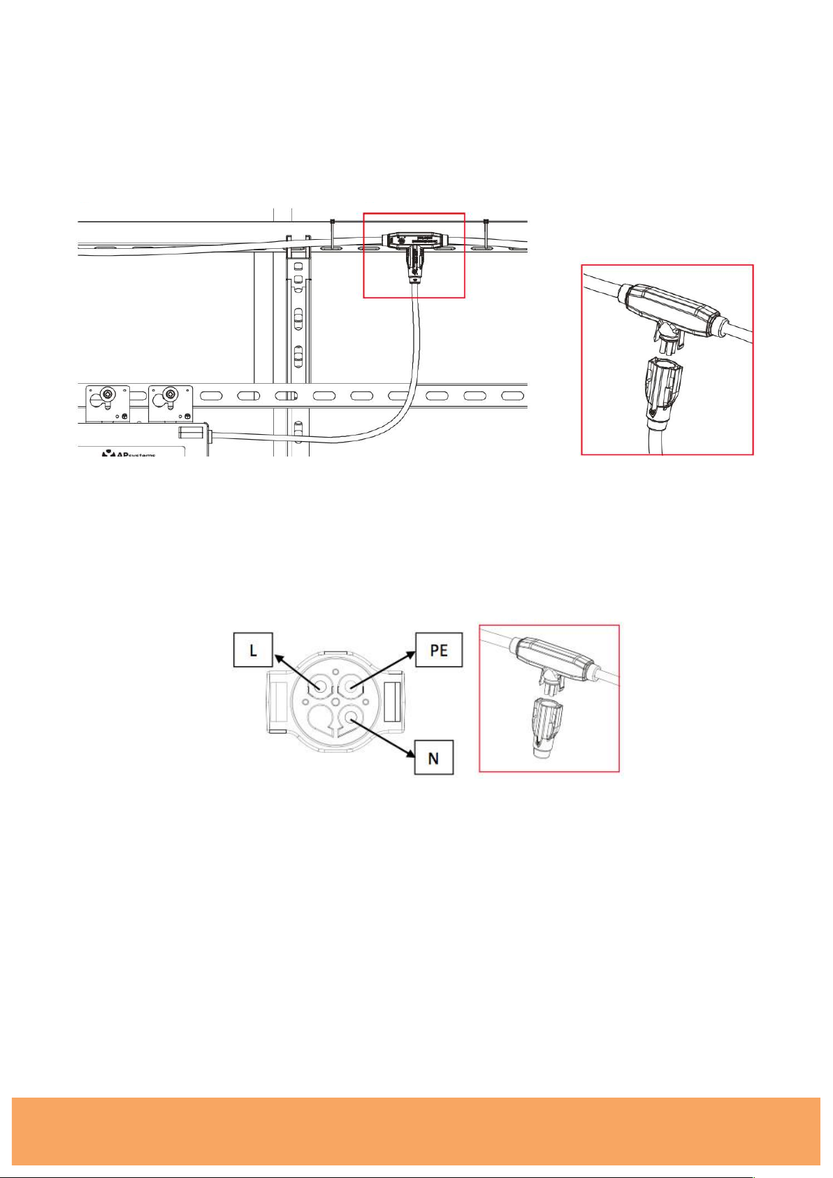
1. Once you have completed installing the roof mount system, attach the Micro-Inverters to Solar
Panel Frames, or railing system using nuts, bolts or Z-Modules provided. You will need your
Hex key and Spanner. Ensure the bolts are tightened securely.
NOTE: If you are unable to bolt the inverter to the solar panel frame, use the additional USupports and Z-Module clamps provided to secure the Micro-Inverter to the railing system. See
images below. (Please refer to the ‘Roof Mount Installation’ section of this manual for information
on how to fix U-Supports)
Each Micro-Inverter has serial number labels affixed. Once the micro-inverters are installed, please
peel one label off each micro-inverter and stick them to the warranty card (please refer to the
‘Completing Your Warranty Card’ section of this installation manual for more information).
Page 11
Plug-In Solar
289 London Road | Burgess Hill | West Sussex | RH15 9QU
www.pluginsolar.co.uk | [email protected] | 01444 672005
Page 11
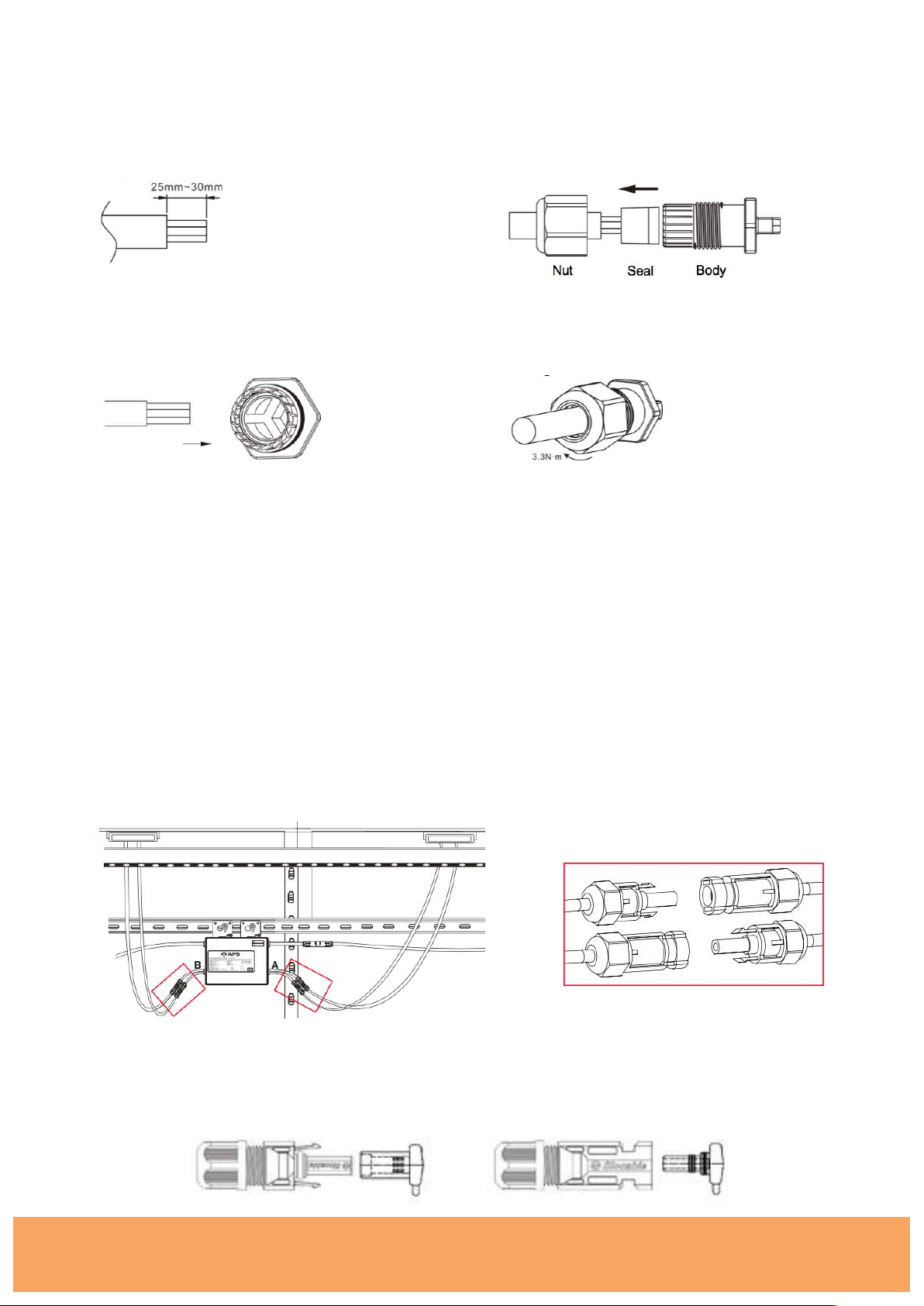
2. Connect the Micro-Inverters to the AC Bus Trunk Cable
Connect the AC connector of the Micro-Inverter to the AC Bus Trunk Cable. Do this for each
Micro-Inverter in your system. Ensure a click is heard as connectors engage. Ensure that all
connections are properly closed.
WARNIING: Do NOT exceed a maximum of (5) five Micro-Inverters in an AC branch circuit when
using the Plug-In Solar System.
Cover any unused connectors on the AC Bus Trunk Cable to protect the connectors. Ensure a
click is heard as connectors engage. Ensure that all connections are properly closed.
Page 12
Plug-In Solar
289 London Road | Burgess Hill | West Sussex | RH15 9QU
www.pluginsolar.co.uk | [email protected] | 01444 672005
Page 12
3. Install Protective End Cap onto the AC Bus Trunk Cable
a. Strip AC Bus Trunk Cable
b. Insert the cable end into the seal. !
c. Insert the wires into the cable clamps.
d. Rotate the nut with 3.3N·m until the
latching mechanism meets the base.
4. Connect Micro Inverters to Solar Panels (PV Modules)
Connect each Solar Panel to the Micro-Inverter DC cables to feed PV power into the Micro
inverter, following the polarity direction marked on each Micro inverter. Ensure a click is heard as
connectors engage.
When plugging in the DC cables, the Micro-Inverter should immediately blink green three times.
This will happen as soon as the cables are plugged in and will show that the Micro-Inverter is
functioning correctly. This entire check function will start and end within 5 seconds of plugging in
the unit, so pay careful attention to these lights when connecting the DC cables.
WARNING: Ensure that all AC and DC wiring is correct. Ensure that none of the AC and DC wires
are pinched or damaged. Ensure that all connections are properly closed.
WARNING: If you are installing an odd number of Solar panels, ensure you use the MC4 sealing
caps provided with your kit to seal the exposed MC4 connectors on the Micro-Inverter.
Page 13
Plug-In Solar
289 London Road | Burgess Hill | West Sussex | RH15 9QU
www.pluginsolar.co.uk | [email protected] | 01444 672005
Page 13
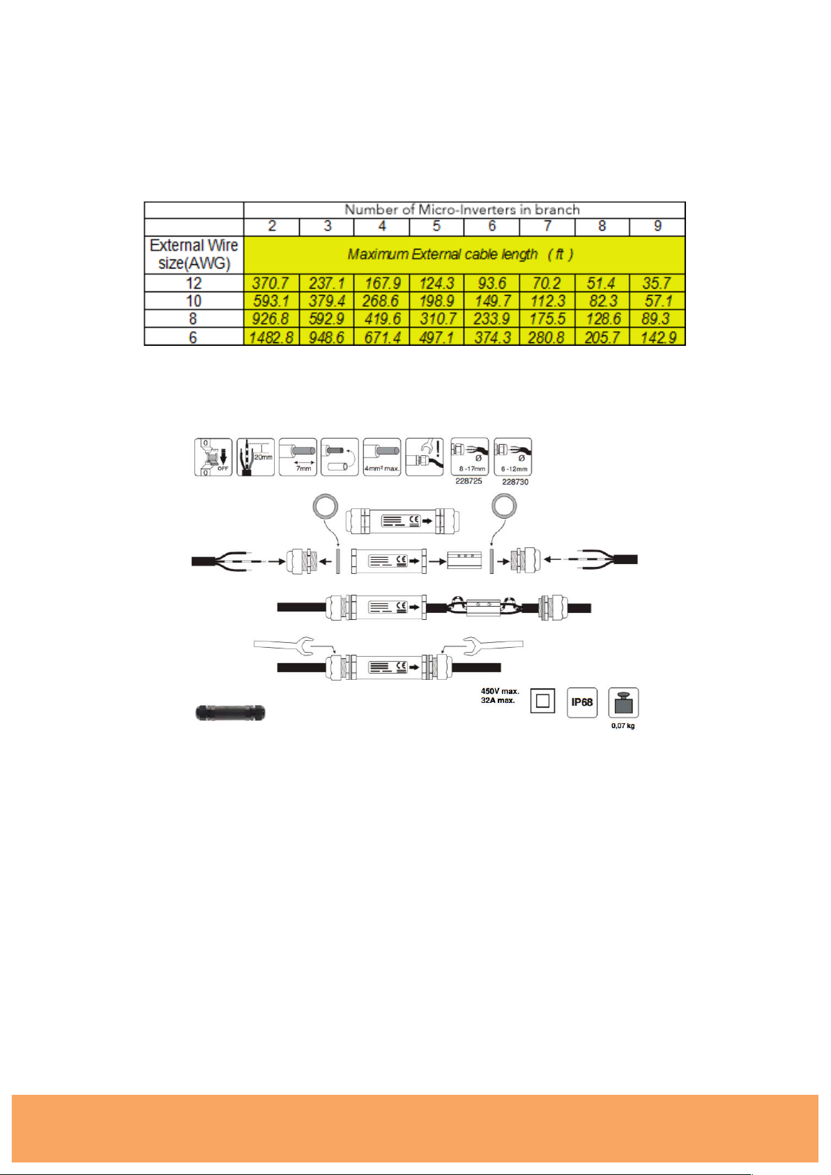
5. If you need to extend the length of AC Bus Trunk Cable, we can supply extra lengths on
request. If you provide your own cable please be sure to use the correct cable wire size (AWG)
depending on distance of the last Micro-Inverter to the connection point and the number of
Micro-Inverters in the branch, as shown in the table below. Please be aware, the longer the
cable run, the greater the power loss.
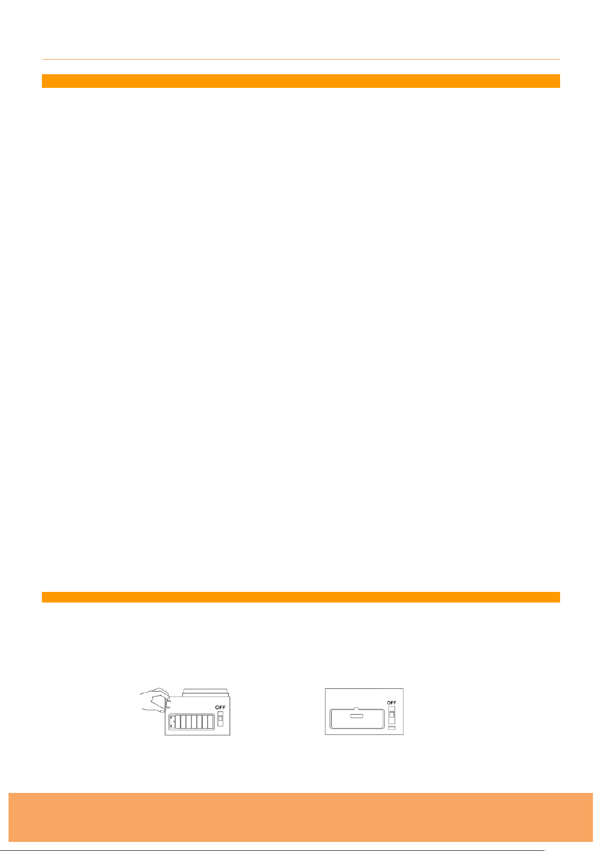
Follow the instructions outlined below to connect the APS AC Bus Trunk Cable to your extension
cable, using a connection box, or similar (supplied upon request).
Page 14
Plug-In Solar
289 London Road | Burgess Hill | West Sussex | RH15 9QU
www.pluginsolar.co.uk | [email protected] | 01444 672005
Page 14
WIRING THE SOLAR TO THE EXISITING MAINS CIRCUIT
IMPORTANT SAFETY INFORMATION – FOR YOUR PROTECTION
Before installation please read these instructions carefully and use the Plug-In Solar Connection Unit in
accordance with these safety wiring instructions.
In older houses, you may find a variety of old fuse boxes where the mains supply comes in. You may also
have wiring and fittings of an older style. These may not be up to the standard required today. If this is the
case, have it all checked and tested by a professional electrician BEFORE carrying out any work on it.
Some old installations may now be dangerous.
Electricity is dangerous. Always disconnect from mains supply before any inspection or repair to equipment.
Safety must always be given top priority. Do not allow children to tamper with electrical devices.
ALWAYS FOLLOW THE IET WIRING REGULATIONS.
You must NOT install the Plug-In Solar Connection Unit in the following locations as set out by Part P:
(a) within a room containing a bath or shower, the space surrounding a bath tap or shower head,
where the space extends —
(i) vertically from the finished floor level to —
(aa) a height of 2.25 metres; or
(bb) the position of the shower head where it is attached to a wall or ceiling at a point
higher than 2.25 metres from that level; and
(ii) horizontally —
(aa) where there is a bath tub or shower tray, from the edge of the bathtub or shower
tray to a distance of 0.6 metres; or
(bb) where there is no bath tub or shower tray, from the centre point of the shower
head where it is attached to the wall or ceiling to a distance of 1.2 metres; or
(b) a room containing a swimming pool or sauna heater.
As an additional precaution, wear rubber-soled shoes. This will provide a measure of insulation between you
and the ground!
IF YOU ARE NOT ABSOLUTELY CERTAIN ABOUT ANY ASPECT OF ELECTRICAL WORK, SEEK PROFESSIONAL ADVICE
1.1. Switch off the power and remove the fuse for the relevant circuit before carrying out any
work, or inspecting, either it, or the appliances connected to it. Never inspect, or carry out work
on, any part of the system with the power on. Make sure that power cannot be inadvertently
restored by someone else.
1.2. Use a voltage tester to check the power to the wires or connections are off before touching
them.
Page 15
Plug-In Solar
289 London Road | Burgess Hill | West Sussex | RH15 9QU
www.pluginsolar.co.uk | [email protected] | 01444 672005
Page 15
1.3. Once the power is disconnected, wire the Plug-In Solar Connection Unit using the following
instructions.
Wire Identification (if in doubt consult a qualified electrician)
EARTH – Green and Yellow Sleeving
LIVE – Red or Brown
NEUTRAL – Blue or Black
a) If using the Plug-In Solar Connection Unit to replace an old socket (or similar), note the cable
connections and wire up the Plug-In Solar Connection Unit the same way as the replaced item, with
earthing as stated in these instructions.
b) Route the cable through the appropriate entry point of the mounting box (this is usually at the rear).
c) Cables should be prepared so sufficient conductor length reaches the terminals. Strip the ends of
the individual conductors so that an adequate length enters the terminals.
d) Carefully arrange the wiring to lie along the edges of the product or box, keeping the central area
clear.
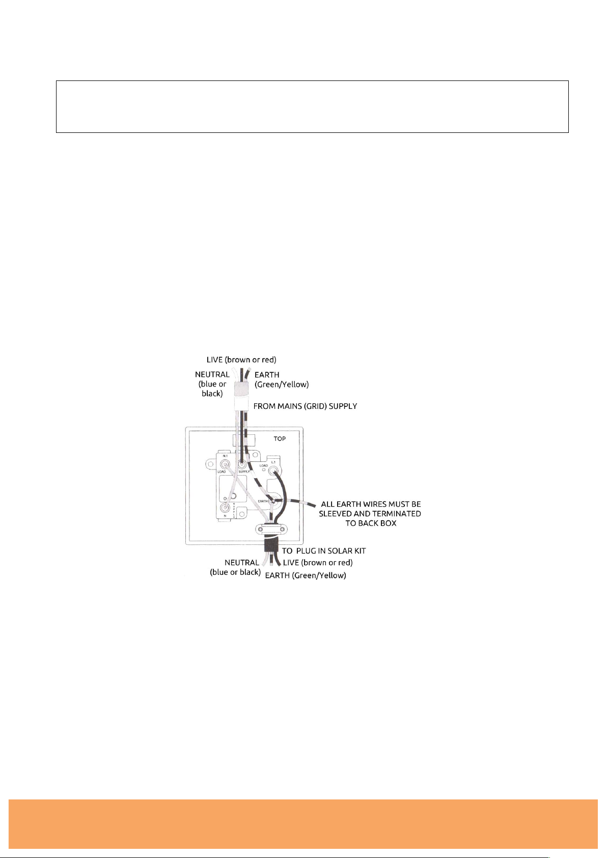
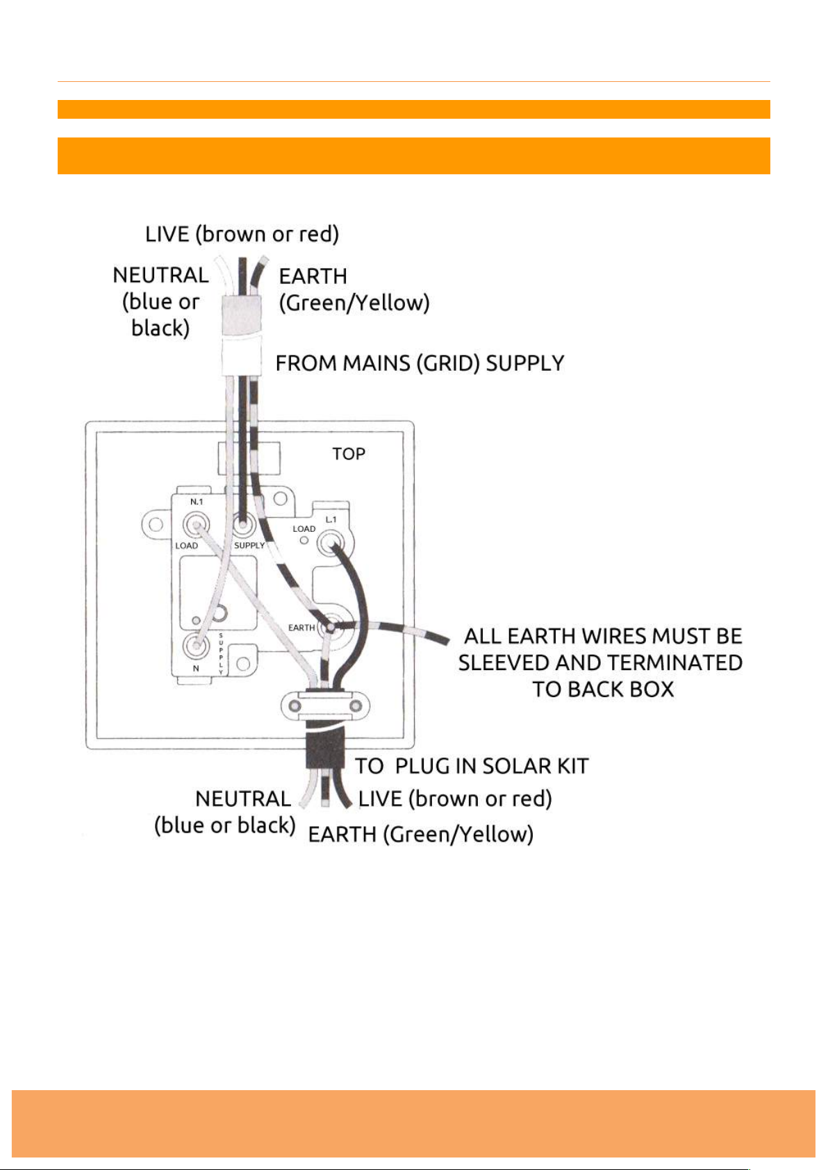
e) Wire the Plug-In Solar Connection Unit using the following diagram (a larger version can be found in
Appendix 1):
f) When connecting the Plug-In Solar Connection Unit ensure that only the bare end of the wire enters
the terminal, and no bare wires are visible. Always tighten the terminal screws, but don’t over
tighten. An earth connection should always be made between the mounting box earth terminal and
the fused connection unit terminal. If the earth wire is bare, it must be sleeved with appropriate
green/yellow sleeving.
g) If you are in any doubt about connecting this product consult a qualified electrician.
1.4. Wiring insulation tests should be completed to avoid misleading instrument readings and
possible internal damage to the unit. Check your work thoroughly before restoring power to the
circuit. If you are not certain, seek professional advice.
1.5. Once power has been restored, your Plug-In Solar kit will be feeding FREE electricity into
your mains circuit.
Page 16
Plug-In Solar
289 London Road | Burgess Hill | West Sussex | RH15 9QU
www.pluginsolar.co.uk | [email protected] | 01444 672005
Page 16
ISOLATION/ISOLATOR REQUIREMENTS
Under G83/2 requirements, it must be possible to isolate a Plug-In Solar kit from the from the
DNO’s Distribution System, using a Double Pole Isolator. This is the function of the Plug-In Solar
Connection Unit.
The Plug-In Solar Connection Unit, is a double pole Switched Fused Connection Unit, that adheres
to British Standard BS1363-4, and offers on load isolation from the grid.
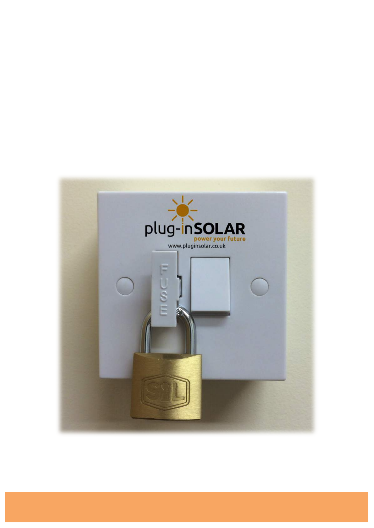
G83/2 regulations also state that the Plug-In Solar Connection Unit is lockable in the OFF position
only. This ensures isolation under maintenance. The Fuse carrier of the Plug-In Solar Connection
Unit can be locked open (the OFF position), as per the image below, in order to meet this
requirement (padlock not provided).
Page 17
Plug-In Solar
289 London Road | Burgess Hill | West Sussex | RH15 9QU
www.pluginsolar.co.uk | [email protected] | 01444 672005
Page 17
PLACING WARNING LABELS
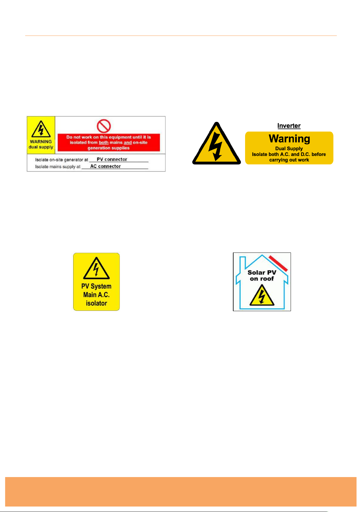
When installing a Plug-In Solar kit you must place labelling at the Plug-In Solar Connection Unit,
Existing Consumer Unit and at all points of isolation between the Plug-In Solar Connection Unit
and the Solar Panels within your premises. This is to indicate the presence of a Small Scale
Embedded Generation installation (SSEG). The labelling should fixed in place to ensure that it
remains legible and secure for the lifetime of the installation. The following labels must be used and
have been provided with your Plug-In Solar kit.
Dual supply labelling should be placed at the
Plug-In Solar Connection Unit between the
PV system and Existing Consumer Unit to
indicate the presence of on-site generation
and indicating the position of the main A.C
switch disconnector.
An APS Inverter should be labelled stating
"Inverter - isolate A.C. and D.C. before carrying
out work". The Micro-Inverters also have this
warning label as standard.
An AC isolator Label should be placed next
to the Plug-In Solar Connection Unit and all
other AC switches/disconnects (if
applicable). ON and OFF positions should
be clearly labelled.
To ensure the Fire and Rescue Service are
aware that Solar is installed on the roof the
following sign shall also be fitted next to the
existing consumer unit in the building. You do
not need this label for Ground Mount systems.
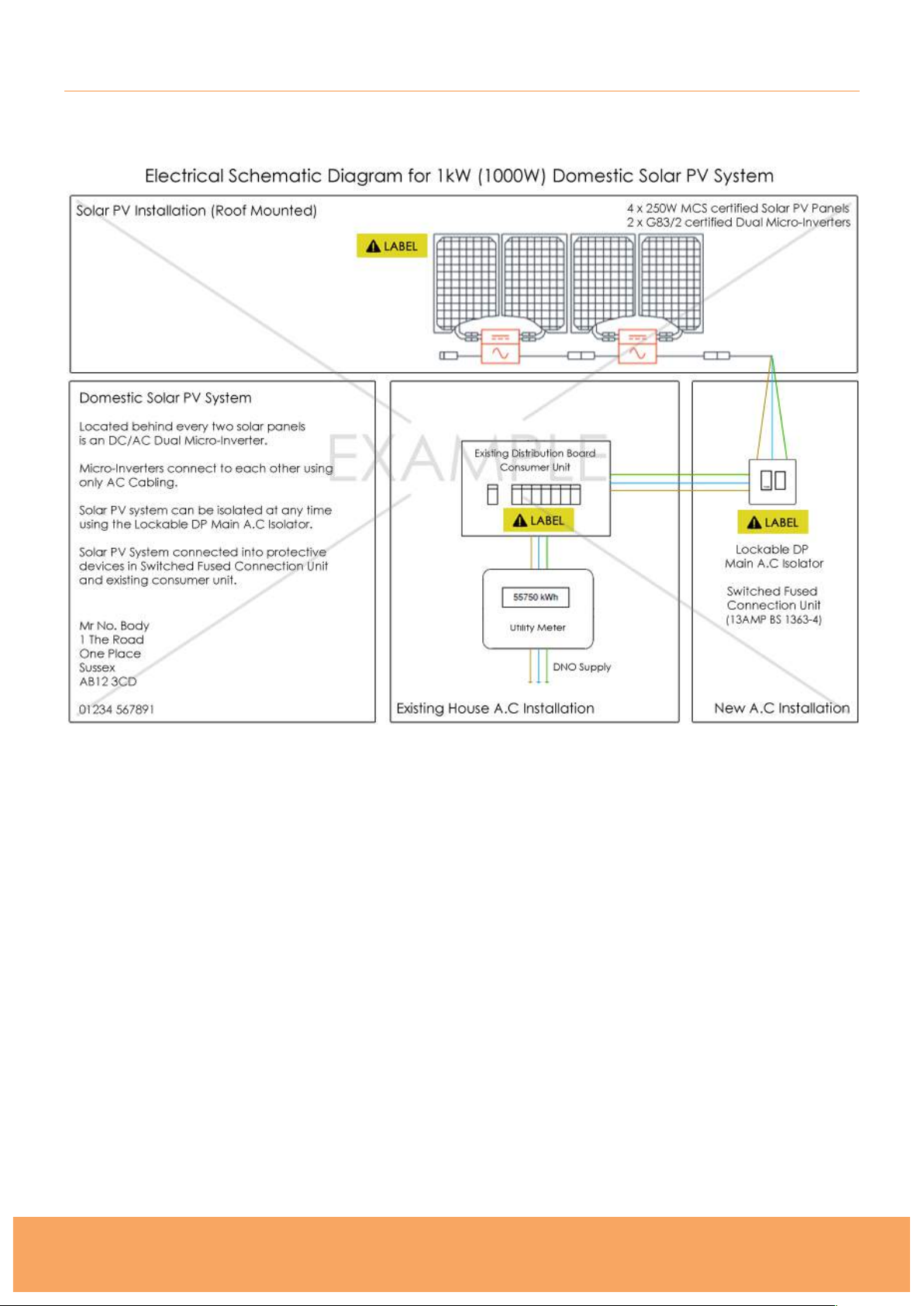
In addition to this safety labelling, you must also display an electrical schematic diagram next to the
existing consumer unit in the property. You will have been provided with an electrical schematic
diagram relevant to your kit, but can see an example in Appendix 3. Please note the diagram in
Appendix 3 is non-prescriptive and is for illustrative purposes only.
Page 18

Plug-In Solar
289 London Road | Burgess Hill | West Sussex | RH15 9QU
www.pluginsolar.co.uk | [email protected] | 01444 672005
Page 18
INSPECTING AND TESTING YOUR PLUG-IN SOLAR INSTALLATION
As part of the G83/2 on-site commissioning tests you shall carry out a functional check of the loss
of mains protection, for example by removing the supply to the Plug-In Solar kit during operation
and checking that the Plug-In Solar Connection Unit operates to disconnect the Plug-In Solar Kit
from the DNO’s Distribution System.
In the UK the installation of a Plug-In Solar Kit is considered non-notifiable electrical work under
Part P of the Building Regulations 2013, as it is an alteration to an existing installation (the mains
grid).
“Regulation 12(6A) sets out electrical installation work that is notifiable. All other electrical
installation work is not notifiable – namely additions and alterations to existing installations outside
special locations, and replacements, repairs and maintenance anywhere.”
Installation of a non-notifiable Plug-In Solar kit should still be designed, installed, inspected, tested
and certificated in accordance with BS 7671.
For more information on how to do this, you can find a copy of Part P building regulations here:
http://www.planningportal.gov.uk/uploads/br/BR_PDF_AD_P_2013.pdf
Page 19
Plug-In Solar
289 London Road | Burgess Hill | West Sussex | RH15 9QU
www.pluginsolar.co.uk | [email protected] | 01444 672005
Page 19
COMMISSIONING YOUR PLUG-IN SOLAR INSTALLATION
Once you have installed, inspected and tested your Plug-In Solar kit, it is a requirement that you
complete and return a G83/2 SSEG Installation Commissioning Confirmation Form to your District
Network Operator (DNO) within 28 days.
Distribution Network Operators (DNOs) own and operate the distribution network of towers and
cables that bring electricity from the national transmission network to homes and businesses. They
don’t sell electricity to consumers, this is done by the electricity suppliers. Informing the DNO of
your installation allows them to manage the grid more effectively.
There are 9 different DNO’s across the UK, so you must make sure you submit your form to the
correct DNO in your area. You can find your DNO by entering your postcode using this website:
https://www.ssepd.co.uk/Whoismynetworkoperator/
Once you have identified your DNO you must download a G83/2 SSEG Installation Commissioning
Confirmation Form from their website (or request that they e-mail one to you).
Completing G83/2 SSEG Installation Commissioning Confirmation Form
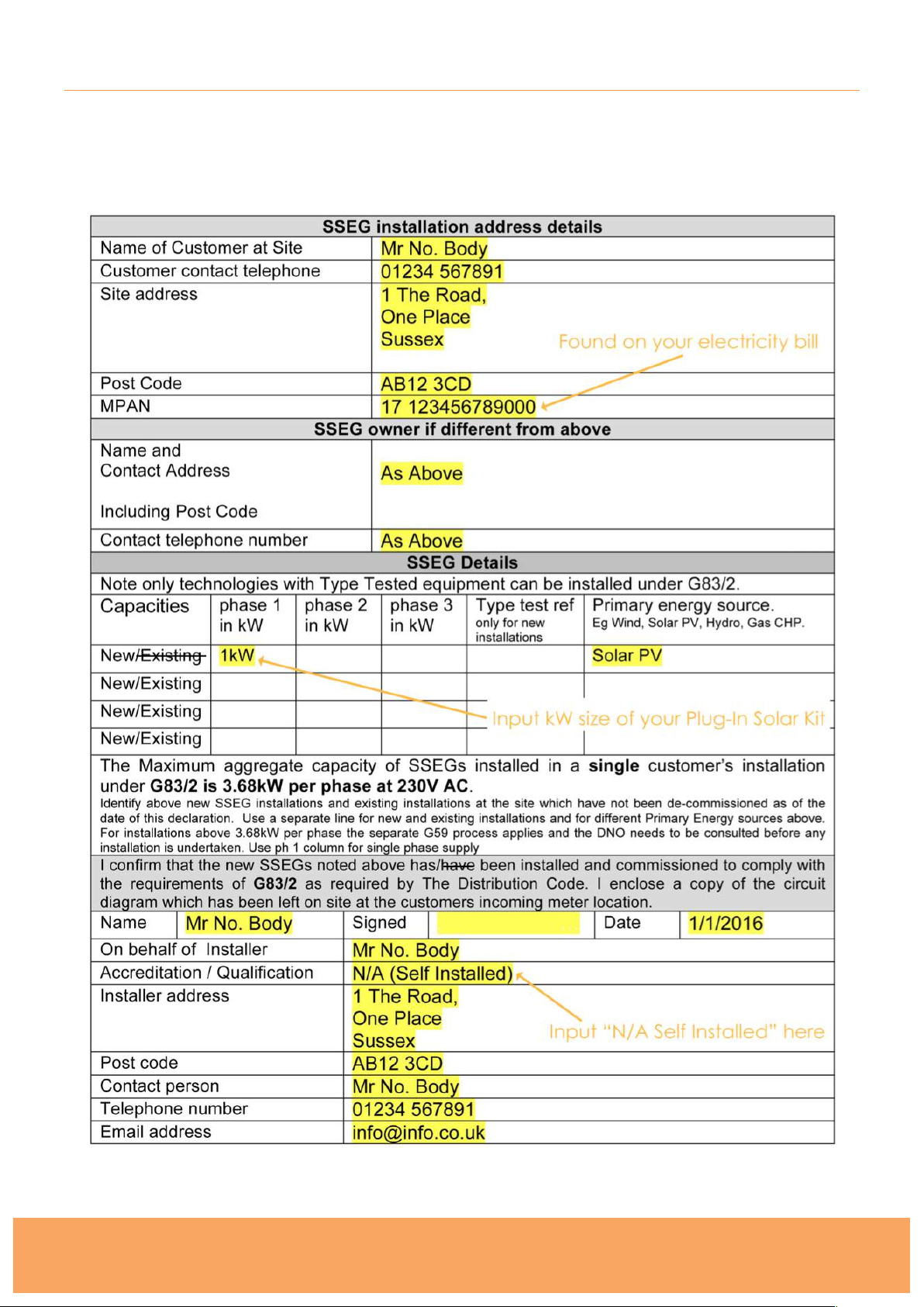
An example G83/2 Commissioning Confirmation Form can be found in Appendix 2 of this
Installation Manual. Please note G83/2 forms differ between DNO’s, this is an example only.
The G83/2 SSEG Installation Commissioning Confirmation Form is relatively self-explanatory,
however there are a number of sections that you must complete correctly:
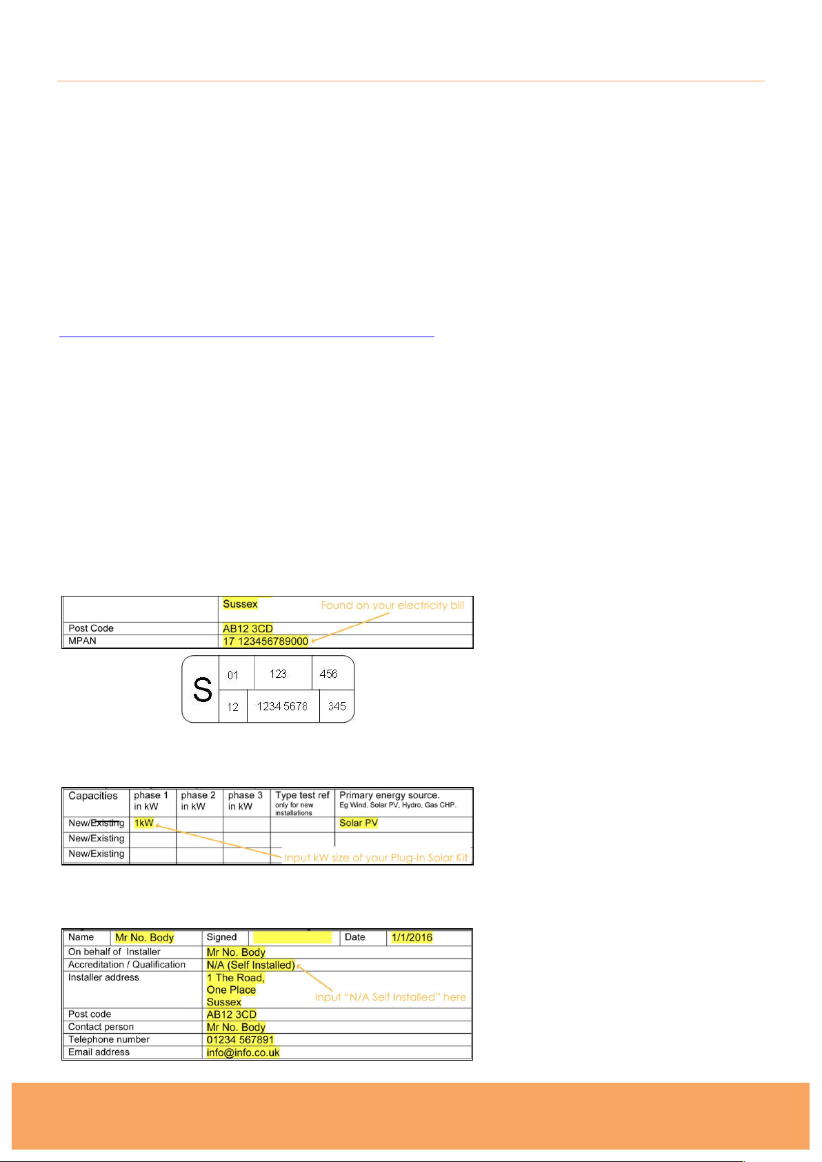
SSEG Installation Address Details Section
A Meter Point Administration Number, also
(MPAN), is a 21-digit reference used in the
UK to uniquely identify electricity supply
points. You must correctly fill in your own
MPAN in this section of the form.
Your MPAN can be found on your electricity
bill and often looks like the image on the left.
SSEG Details Section
Within the SSEG Details section of the form,
fill in the details of your installation. The
capacity will be the size of the Plug-In Solar
kit you purchased, i.e. 1kW. The Primary
Energy Source must always be filled as ‘Solar
PV’. If you have any existing SSEG’s (e.g.
wind/solar) you must also declare these here.
SSEG Installer Details Section
As Plug-In Solar kits are DIY, self installed
solar systems you should complete this
section as the installer. In the
Accreditation/Qualification section you should
fill this in as ‘N/A (Self-Installed)’, unless you
have an appropriate accreditation. This
section of the form also needs to be signed.
Page 20

Plug-In Solar
289 London Road | Burgess Hill | West Sussex | RH15 9QU
www.pluginsolar.co.uk | [email protected] | 01444 672005
Page 20
Along with the completed G83/2 SSEG Installation Commissioning Confirmation Form, you must
also supply the DNO with the following:
1. An electrical schematic diagram for your installation (A relevant electrical schematic diagram will be
provided with your Plug-In Solar Kit). An example can be seen in Appendix 3.
2. A copy of the G83/2 SSEG Test Report Certificate for the Micro-Inverters (These can be found in
Appendix 7)
3. A photograph of your existing electricity meter (be sure to include the make and model of the meter)
Email/Fax/Post the information above to your DNO using the contact supplied on the
Commissioning Form. Do not send it to Plug-In Solar; we cannot apply to the DNO on your behalf.
When the DNO has received your form and it has been processed, you will get a confirmation
email/letter to say it has been accepted.
Notifying the DNO of changes to a Plug-In Solar kit
If during the lifetime of the Plug-In Solar kit it is necessary to replace a major component of the
Plug-In Solar kit, it is only necessary to notify the DNO if the operating characteristics of the Plug-In
Solar kit or the Plug-In Solar Connection Unit have been altered when compared against the unit
that was originally commissioned.
Notifying the DNO of the decommissioning of a Plug-In Solar kit
In the event that a Plug-In Solar kit is to be decommissioned and will no longer operate as a
source of electrical energy in parallel with the DNO’s Distribution System, you must notify the DNO
by completing a G83/2 SSEG Decommissioning Confirmation Form. Please contact your DNO for
a copy of this form.
Page 21
Plug-In Solar
289 London Road | Burgess Hill | West Sussex | RH15 9QU
www.pluginsolar.co.uk | [email protected] | 01444 672005
Page 21
COMPLETING YOUR WARRANTY CARD
In order to fulfill the requirements of the manufacturers, you must complete Warranty Cards for the
Micro-Inverters, which provide system information and installation maps to APS. A Warranty Card
can be found in Appendix 6.
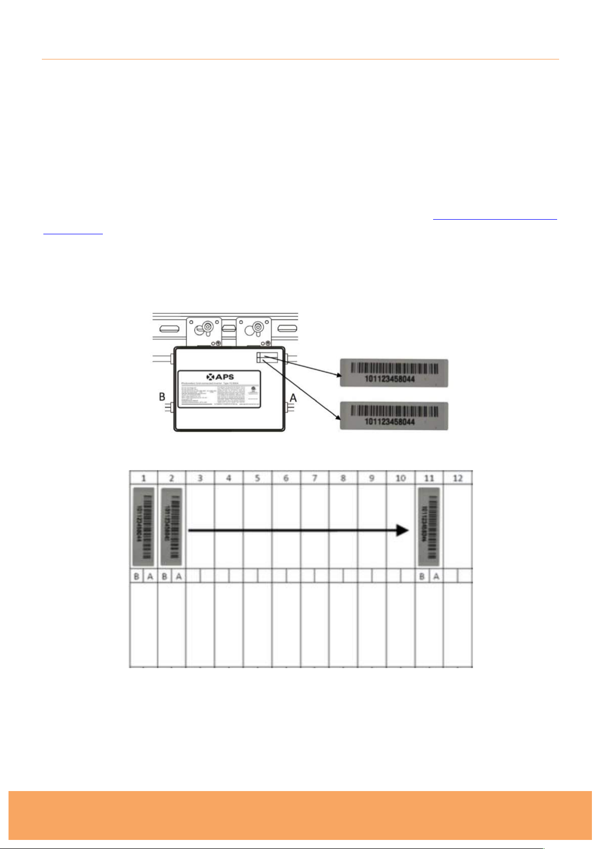
Each Micro-Inverter has serial number labels affixed. Once the inverters are installed, please peel
one of the labels off each Micro-Inverter and affix them to the warranty card.
Fill in the warranty card with each of the labels according to the layout on the roof/ground.
For APS Micro-Inverters, fill the warranty card and email to APS at emasupport@altenergy-
power.com.
If you have a purchased an online monitoring system, please refer to the User Manual provided
with this guide for detailed instructions on how to install it correctly, and use these installation
maps to set it up.
Page 22
Plug-In Solar
289 London Road | Burgess Hill | West Sussex | RH15 9QU
www.pluginsolar.co.uk | [email protected] | 01444 672005
Page 22
APPENDIX 1. PLUG-IN SOLAR CONNECTION UNIT – WIRING DIAGRAM
ALWAYS FOLLOW THE IET WIRING REGULATIONS
IF YOU ARE NOT ABSOLUTELY CERTAIN ABOUT ANY ASPECT OF ELECTRICAL WORK,
SEEK PROFESSIONAL ADVICE
Page 23
Plug-In Solar
289 London Road | Burgess Hill | West Sussex | RH15 9QU
www.pluginsolar.co.uk | [email protected] | 01444 672005
Page 23
APPENDIX 2. EXAMPLE G83/2 COMMISSIONING CONFIRMATION FORM
Please note, G83/2 SSEG Installation Commissioning Confirmation Forms differ between DNO’s
and this may not look like the form you receive. This is non-prescriptive and is for illustrative
purposes only.
Page 24
Plug-In Solar
289 London Road | Burgess Hill | West Sussex | RH15 9QU
www.pluginsolar.co.uk | [email protected] | 01444 672005
Page 24
APPENDIX 3. EXAMPLE ELECTRICAL SCHEMATIC DIAGRAM
This is non-prescriptive and is for illustrative purposes only.
Page 25

Plug-In Solar
289 London Road | Burgess Hill | West Sussex | RH15 9QU
www.pluginsolar.co.uk | [email protected] | 01444 672005
Page 25
APPENDIX 4. TROUBLESHOOTING APS DUAL MICRO-INVERTERS
Status Indications and Error Reporting
Startup LED
When DC power is first applied to the Micro-Inverter: Three short green blinks indicate a successful
Micro-Inverter startup.
Operation LED
Flashing Slow Green (10s gap) - Producing power and communicating with ECU
Flashing Fast Green (2s gap) – Producing power and not communicating with ECU
Flashing Red – Not producing power
GFDI Error
A solid red LED indicates the Micro-Inverter has detected a ground fault (GFDI) error in the PV
system. Unless the GFDI error has been cleared, the LED will remain red and the ECU will keep
reporting the fault.
After the ground fault error is fixed, follow the instructions in the ECU Installation and Operation
Manual to clear this GFDI error reporting.
Non-Operating Micro-Inverters
1. To troubleshoot a non-operating APS Micro-Inverter, follow the steps below in order:
2. Check the connection to the utility grid. Verify utility power is present at the inverter in question
by removing AC, then DC power. Never disconnect the DC wires while the Micro-Inverter is
producing power. Re-connect the DC module connectors and watch for three short green LED
flashes. !
3. Check the AC branch circuit interconnection between all the Micro-Inverters. Verify each micro-
inverter is energised by the utility grid as described in the previous step. !
4. Make sure that any AC breakers are functioning properly and are closed.
5. Check the DC connections between the Micro-Inverter and the PV module. !
6. If the problem persists, please contact APS Energy customer support on 0031-10-2582670 or
email [email protected]. DO NOT attempt to repair the APS Micro-Inverter. If
troubleshooting methods fail, please return the Micro-Inverter to your distributor for
replacement. !
Page 26
Default/ Extended (year)
China
Others
YC500
5/5
10/25
YC250
5/5
10/25
YC1000-3
5/5
10/25
ECU
1/1
1/1
Accessories
1/1
1/1
Note: Extra fees apply to extended warranty.
ALTENERGY POWER SYSTEM INC. QW-SA-01 B/1
Warranty Regulations and Liability
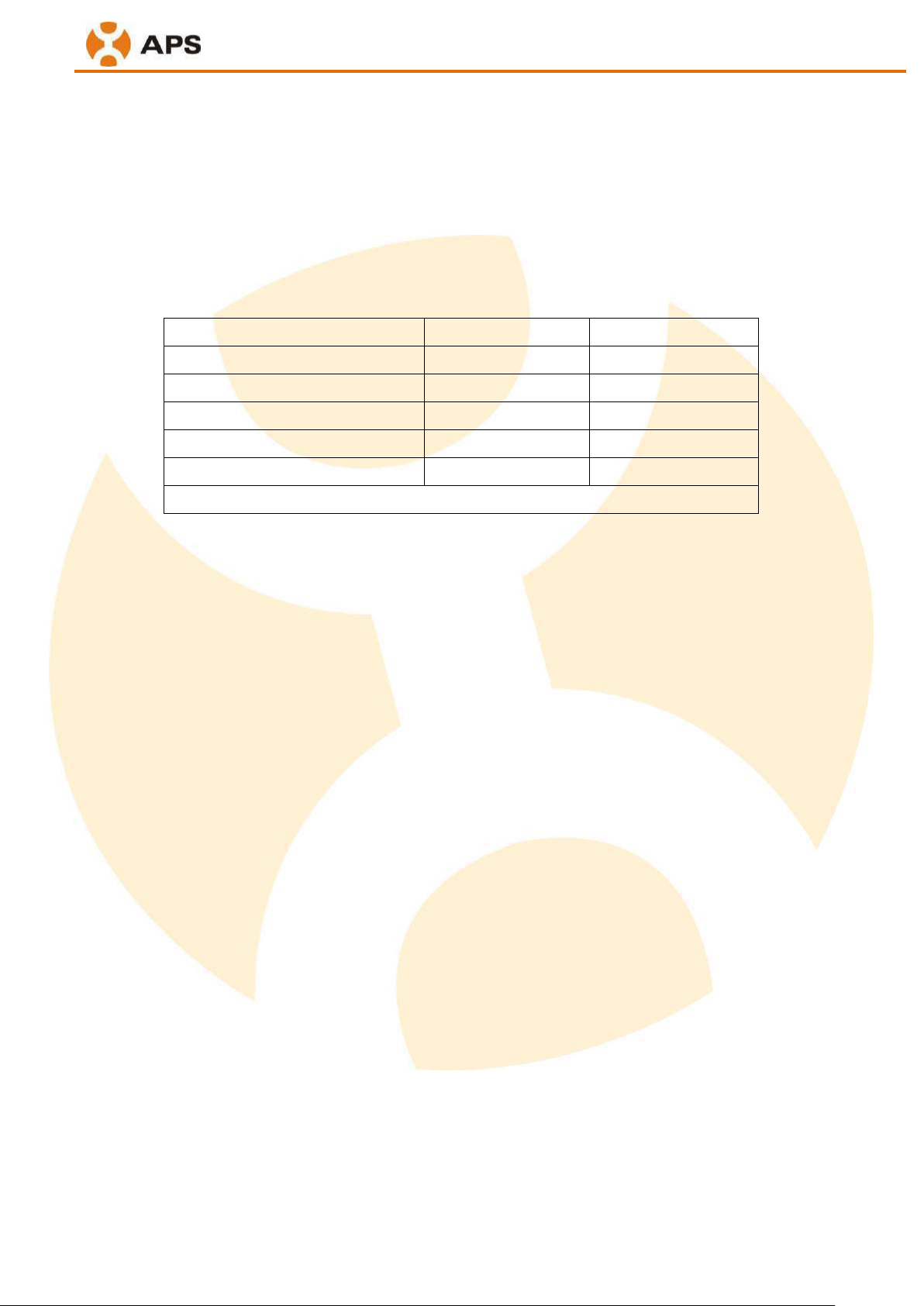
Altenergy Power System (APS) products are designed to withstand normal operating conditions when
used for its originally intended purpose in compliance with the APS User Manual supplied with the
originally shipped system. The APS limited warranty (“Limited Warranty”) covers defects in
workmanship and materials of the APS products (“Defective Product”). APS provides both default
warranty and extended warranty as follows which starts from the shipping date.
During the Warranty Period, APS will, at its option, repair or replace the Defective Product free of
charge, provided APS, through inspection, establishes the existence of a defect that is covered by the
Limited Warranty. APS will, at its option, use new and/or reconditioned parts in repairing or replacing
the Defective Product. APS reserves the right to use parts or products of original or improved design in
the repair or replacement of Defective Product. If APS repairs or replaces a Defective Product, the
Limited Warranty continues on the repaired or replacement product for the remainder of the original
Warranty Period or ninety (90) days from the date of APS’s return shipment of the repaired or
replacement product, whichever is later.
The Limited Warranty covers both parts and labor necessary to repair the Defective Product, but does
not include labor costs related to un-installing the Defective Product or re-installing the repaired or
replacement product. The Limited Warranty also covers the costs of shipping repaired or replacement
product from APS, via a non-expedited freight carrier selected by APS.
The Limited Warranty does not cover, and APS will not be responsible for, shipping damage or damage
caused by mishandling by the freight carrier and any such damage is the responsibility of the freight
carrier.
To obtain repair or replacement service under this Limited Warranty, the customer must comply with
the following policy and procedure:
All Defective Product must be returned with a Return Merchandise Authorization (RMA) number
which customer must request from APS. Before requesting the RMA, however, the customer should
contact an APS technical support representative to evaluate and troubleshoot the problem while the
APS product is in the field, since many problems can be solved in the field.
If in-field troubleshooting does not solve the problem, customer may request the RMA number, with
following information:
1
Page 27
ALTENERGY POWER SYSTEM INC. QW-SA-01 B/1
- Proof-of-purchase of the Defective Product in the form of (1) the dated purchase receipt
from the original purchase of the product at point of sale to the end user, or (2) the dated
dealer invoice or purchase receipt showing original equipment manufacturer (OEM) status,
or (3) the dated invoice or purchase receipt showing the product exchanged under warranty.
- Model number of the Defective Product
- Serial number of the Defective Product
- Detailed description of the defect
- Shipping address for return of the repaired or replacement product
All Defective Product authorized for return must be returned in the original shipping container or
other packaging that is equally protective of the product.
The returned Defective Product must not have been disassembled or modified without the prior
written APS authorization.
The Limited Warranty does not apply to, and APS will not be responsible for, any defect in or damage to
any APS product: (1) “Warranty card” is not returned to APS; (2) that has been misused, neglected,
tampered with, altered, or otherwise damaged, either internally or externally; (3) worn out appearance ,
including discolor and scratch; (4) the defective has no impact on the electricity generation, including
LED failure; (5) that has been improperly installed, operated, handled or used, including use under
conditions for which the product was not designed, use in an unsuitable environment, or use in a
manner contrary to the APS User Manual or applicable laws or regulations; (6) that has been subjected
to fire, water, generalized corrosion, biological infestations, or input voltage that creates operating
conditions beyond the maximum or minimum limits listed in the APS product specifications, including
high input voltage from generators or lightning strikes; (7) that has been subjected to incidental or
consequential damage caused by defects of other components of the solar system; or (8) if the original
identification markings (including trademark or serial number) of such product have been defaced,
altered, or removed; (9) changed the owner, but isn’t assigned. The Limited Warranty does not cover
costs related to the removal, installation or troubleshooting of the customer's electrical systems. The
Limited Warranty does not extend beyond the original cost of the APS product.
THE LIMITED WARRANTY IS THE SOLE AND EXCLUSIVE WARRANTY GIVEN BY APS AND, WHERE
PERMITTED BY LAW, IS MADE EXPRESSLY IN LIEU OF ALL OTHER WARRANTIES, EXPRESS OR IMPLIED,
STATUTORY OR OTHERWISE, INCLUDING, WITHOUT LIMITATION, WARRANTIES OF TITLE, QUALITY,
MERCHANTABILITY, FITNESS FOR A PARTICULAR PURPOSE OR NON-INFRINGEMENT OR WARRANTIES
AS TO THE ACCURACY, SUFFICIENCY OR SUITABILITY OF ANY TECHNICAL OR OTHER INFORMATION
PROVIDED IN MANUALS OR OTHER DOCUMENTATION. IN NO EVENT WILL APS BE LIABLE FOR ANY
SPECIAL, DIRECT, INDIRECT, INCIDENTAL OR CONSEQUENTIAL DAMAGES, LOSSES, COSTS OR
EXPENSES HOWEVER ARISING, WHETHER IN CONTRACTOR TORT, INCLUDING WITHOUT LIMITATION
ANY ECONOMIC LOSSES OF ANY KIND, ANY LOSS OR DAMAGE TO PROPERTY, OR ANY PERSONAL
INJURY.
To the extent any implied warranties are required under applicable law to apply to the APS products,
such implied warranties shall be limited in duration to the Warranty Period, to the extent permitted by
applicable law. Some states and provinces do not allow limitations or exclusions on implied warranties
or on the duration of an implied warranty or on the limitation or exclusion of incidental or consequential
2
Page 28
ALTENERGY POWER SYSTEM INC. QW-SA-01 B/1
damages, so the above limitation(s) or exclusion(s) may not apply. This Limited Warranty gives the
customer specific legal rights, and the customer may have other rights that may vary from province to
province.
ALTENERGY POWER SYSTEM INC
Http: www.apsmicroinverter.com
Email: [email protected]
APS USA
Add: 19925 Stevens Creek Blvd, Suite 100, Cupertino, CA 95014
Tel: 01 (408)-973-7888
Washington Office
Add: 1015 Hostmark St., Suite 104, Poulsbo, WA 98370
Tel: 01-206-855-5100
APS Australia
Add: 6/11-17 Banks Street, Mays Hill, NSW 2145
Tel:+ (02) 9633 3478
APS China
Add: Rm. B403 No.188, Tomson Center, Zhangyang Road, Pudong, Shanghai 200120, China
Tel:+86-21-3392-8205
3
Page 29
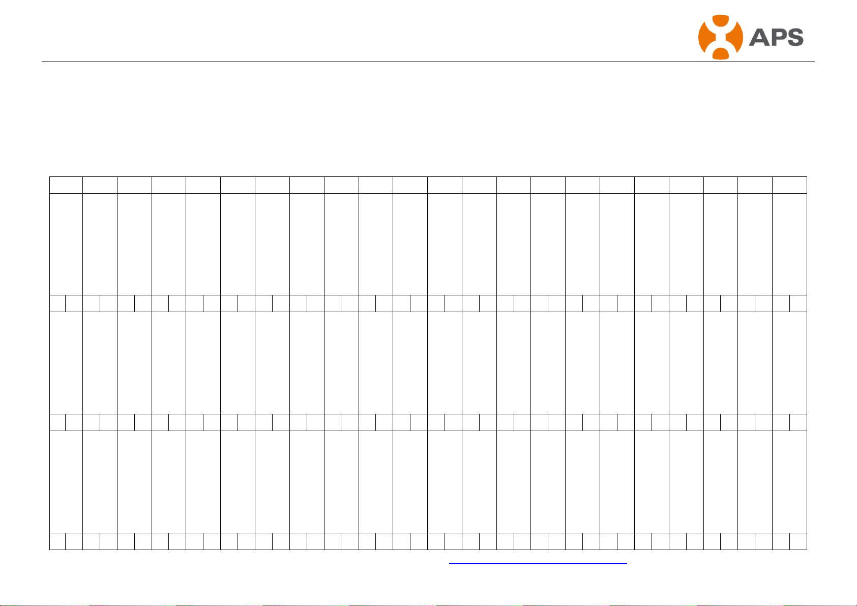
Version:2.1
23
APS Microinverter &Energy Communication Unit
Warranty Card
The APS Installation Map is a diagram of the physical location of each microinverter in your PV installation. Each APS microinverter has a removable serial
number label located on the mounting plate. Peel the label and affix it to the respective location on the APS installation map.
Installation Map Template
1 2 3 4 5 6 7 8 9
10
11
12
13
14
15
16
17
18
19
20
21
22
To register your APS microinverter, please mail this warranty registration card to: [email protected]
Page 30
Page 31

Perlight Solar Co., Ltd.
浙江宝利特新能源股份有限公司
© Perlight Solar 2015 www.perlight.com Page1of
4
Limited Warranty for PV Modules
Warranty Terms 2015
Perlight Solar Co., Ltd. (“Perlight”) warrants its Modules’ performance according to this warranty.
The following family products apply to this Warranty:
Intenergy brand Mono-crystalline modules:
INE-xxxM-72 pcs 6'' (where xxx= 245W - 320W in increment of 5 Watts)
INE-xxxM-60 pcs 6'' (where xxx= 220W - 270W in increment of 5 Watts)
INE-xxxM-54 pcs 6'' (where xxx= 185W - 240W in increment of 5 Watts)
INE-xxxMB-72 pcs 6'' (where xxx= 245W - 320W in increment of 5 Wa tts)
INE-xxxMB-60 pcs 6'' (where xxx= 220W - 270W in increment of 5 Wa tts)
INE-xxxMB-54 pcs 6'' (where xxx= 185W - 240W in increment of 5 Wa tts)
INE-xxxM-96 pcs 5'' (where xxx= 230W - 280W in increment of 5 Watt s)
INE-xxxM-72 pcs 5'' (where xxx= 160W - 210W in increment of 5 Watt s)
INE-xxxM-36 pcs 5'' (where xxx= 80W - 105W in increment of 5 Watts)
INE-xxxMB-96 pcs 5'' (where xxx= 230W - 280W in increment of 5 Watts)
INE-xxxMB-72 pcs 5'' (where xxx= 160W - 210W in increment of 5 Watts)
INE-xxxMB-36 pcs 5'' (where xxx= 80W - 105W in increment of 5 Watts)
Intenergy brand Poly-crystalline modules:
INE-xxxP-72 pcs 6'' (where xxx= 235W - 320W in increment of 5 Watts)
INE-xxxP-60 pcs 6'' (where xxx= 190W - 265W in increment of 5 Watts)
INE-xxxP-54 pcs 6'' (where xxx= 180W - 240W in increment of 5 Watts)
1. Limited Product Warranty – Twelve Years Repair, Replacement or Refund Remedy
Perlight Solar Co., Ltd. (Perlight Solar) warrants its Photovoltaic Solar Modules ( MODULES ), including
factory-assembled DC connectors and cables, if any, to be free from defect in materials and workmanship under normal
application, installation, use and service conditions. If MODULES fail to conform to this warranty, during the period
ending Twelve (12 ) years from the date of sale as shown in the invoice to the first consumer customer of the Perlight
Solar product ( CUSTOMER ), Perlight Solar will, at its option, either repair or replace the product, or refund the
purchase price as paid by the CUSTOMER. The repair or replacement or refund remedy shall be the sole and exclusive
remedy provided under the “Limited Product Warranty” and shall not extend beyond the Twelve (12 ) years period set
forth herein. This “Limited Product Warranty” does not warrant a specific power output, which shall be exclusively
covered under clause 2 hereinafter ( “Limited Peak Power Warranty” ).
2. Limited Peak Power Warranty - Limited Remedy
12 years
If, within a period of twelve ( 12 ) years from the date shown in the invoice to the CUSTOMER any MODULE(s)
exhibits a power output less than 90 % of the minimum “Peak Power at STC”(standard test conditions) as specified at
the date of invoice in Perlight Solar´s Product Information Sheet. The actual power output of the module shall be
determined for verification using Standard Testing Conditions only. The actual power output measurement is either
carried out by a Perlight Solar facility or by a Perlight Solar recognized 3rd party testing institute. Testing equipment
tolerances will be applied to all actual power output measurements. And such loss in power is determined by
Perlight, at its sole discretion, to be due to the Modules’ defects in material or workmanship attributed to
Perlight, and Perlight will, at its sole option and discretion, either (1) make up such loss in power by
providing to Customer additional Modules or provide an appropriate residual market value of the product(s)
as compensation; or (2) repair or replace the defective Modules including free shipping to the place supplied
by Perlight.
Page 32

Perlight Solar Co., Ltd.
浙江宝利特新能源股份有限公司
© Perlight Solar 2015 www.perlight.com Page2of
4
25 years
If, within a period of twelve ( 25 ) years from the date shown in the invoice to the CUSTOMER any MODULE(s)
exhibits a power output less than 80 % of the minimum “Peak Power at STC”(standard test conditions) as specified at
the date of invoice in Perlight Solar´s Product Information Sheet. The actual power output of the module shall be
determined for verification using Standard Testing Conditions only. The actual power output measurement is either
carried out by a Perlight Solar facility or by a Perlight Solar recognized 3rd party testing institute. Testing equipment
tolerances will be applied to all actual power output measurements. And such loss in power is determined by
Perlight, at its sole discretion, to be due to the Modules’ defects in material or workmanship attributed to
Perlight, and Perlight will, at its sole option and discretion, either (1) make up such loss in power by
providing to Customer additional Modules or provide an appropriate residual market value of the product(s)
as compensation; or (2) repair or replace the defective Modules including free shipping to the place supplied
by Perlight.
The remedies set forth in this clause 2 shall be the sole and exclusive remedies provided under the “Limited Peak
Power Warranty”.
3. Exclusions and Limitations
(1) In any event, all warranty claims must be filed within the applicable warranty period.
(2) The “Limited Product Warranties” and the ”Limited Peak Power Warranties” do not apply to any MODULES
which have been subjected to:
Misuse, abuse, neglect or accident;
Alteration, improper installation or application;
Non-observance of Perlight Solar’ s installation and maintenance instructions;
Repair or modifications by someone other than an approved service technician of Perlight Solar;
Power failure surges, lightning, flood, fire, accidental breakage or other events outside Perlight Solar’s
control.
(3) Both, the “Limited Product Warranties” and “Limited Peak Power Warranties” do not cover any transportation
charge, customs clearance or any other costs for return of the MODULES, or for reshipment of any repaired or replaced
MODULES, or costs associated with installation, removal or reinstallation of the PV-modules.
(4) Warranty claims will not be honored if the type or serial number of the MODULES have been altered, removed or
made illegible.
(5) In addition, the limited warranties do not apply to any cosmetic change in appearance stemming from
the normal wear and tear over time of product materials. Any color change on module or any other
changes on module appearance do not represent defects, insofar as the change in appearance does not
stem from defects in material and/or workmanship, and does not cause degradation of functionality of
the module, which are exempt from this warranty.
4. Limitation of Warranty Scope
These “Limited Warranties for PV Modules” as set forth herein are expressly in lieu of and exclude all other express or
implied warranties, including but not limited to warranties of merchantability and of fitness for particular purpose, use,
or application, and all other obligations or liabilities on the part of Perlight Solar, unless such other obligations or
liabilities are expressly agreed to in writing signed and approved by Perlight Solar. Perlight Solar shall have no
responsibility or liability whatsoever for damage or injury to persons or property, or for other loss or injury resulting
from any cause whatsoever arising out of or related to the MODULES, including, without limitation, any defects in the
MODULE, or from use or installation. Under no circumstances shall Perlight Solar be liable for incidental,
consequential or special damages, howsoever caused. Loss of use, loss of profits, loss of production, and loss of
Page 33

Perlight Solar Co., Ltd.
浙江宝利特新能源股份有限公司
© Perlight Solar 2015 www.perlight.com Page3of
4
revenues are specifically and without limitation excluded. Perlight Solar´s aggregate liability, if any, in damages or
otherwise, shall not exceed the invoice value as paid by the CUSTOMER, for the single unit of MODULE.
5. Obtaining Warranty Performance
If the CUSTOMER feels a justified claim covered by this “Limited Warranties for PV Modules”, an immediate
notification directly to Perlight Solar shall be filed by mailing a [registered/certified] letter in writing to the address of
Perlight Solar listed hereunder, or, sending an email letter to the email account of Perlight Solar listed hereunder.
Together with the notification, the CUSTOMER should enclose the evidence of the claim with the corresponding serial
number of the MODULE(s) and the invoice on which the MODULES have been purchased.An invoice with clear
indication of the purchase date, purchase price, module type, stamp or signature of Perlight or its distributors
should also be submitted as part of the evidence.
If the Modules will be returned to Perlight for inspection, repair or replacement by Perlight, Perlight will
give the Customer a Return Merchandise Authorization (RMA). However, Perlight will not accept a return of
any Modules without an RMA.
6. Disputes
In case of any discrepancy in a warranty-claim, a first-class international test-institute be negotiated by both party, shall
be involved to judge the claim finally. All fees and expenses shall be born by the losing party, unless otherwise
awarded. The final explanation right shall be borne by Perlight Solar. The applicable law for the product manufacturing
countries related legal provisions. Any Understand ambiguity, the Chinese shall prevail.
7. Various
The repair or replacement of the MODULES or the supply of additional MODULES, does not cause the beginning of
new warranty terms, nor shall the original terms of this “Limited Warranty for PV-Modules” be extended. Any replaced
MODULES shall become the property of Perlight Solar made for their disposal. Perlight Solar has the right to deliver
another type ( different in size, color, shape and/or power ) in case Perlight Solar discontinued producing the replaced
MODULES at the time of the claim.
8. Force Majeure
Perlight Solar shall not be responsible or liable in any way to the customer or any third-party arising from any
non-performance or delay in performance of any terms and conditions of sale, including this "Limited Warranty for
PV Modules", due to acts God, war, riots, strikes, warlike conditions, plague or other epidemics, fire, flood, or any
other similar cause or circumstance beyond the reasonable control of such Perlight. In such cases, performance by
Perlight of this Limited Warranty shall be suspended without liability for the period of delay reasonably attributable
to such causes.
9. Validity
This “Limited Power Warranty for PV Modules“ is valid for all MODULES dispatched between 1st January 2015
and 31st December 2015.
“Peak Power at STC” is the power in Watt peak that a PV- module generates in its Maximum Power Point. “STC”
are as follows
(a) A light spectrum of AM 1.5,
(b) An irradiation of 1000W per m2,
(c) A cell temperature of 25 degree centigrade at right angle irradiation. The measurements are carried out in
accordance with IEC 61215 as tested at the connectors or junction box terminals – as applicable – per calibration and
Page 34

Perlight Solar Co., Ltd.
浙江宝利特新能源股份有限公司
© Perlight Solar 2015
www.perlight.com Page 4 of 4
testing standards of Perlight Solar valid at the date of manufacture of the PV-modules.
NOTES:
“Peak Power” is the power in watt peak that a PV-module generates in its maximum power point under
STC condition. ‘STC’ are as follows: (a) light spectrum of AM 1.5, (b) an irradiation of 1,000W/m2 and (c)
a cell temperature of 25 degree Centigrade at right angle irradiation. The measurements are carried out in
accordance with IEC61215 as tested at the junction box terminals per the calibration and testing standards
of Jinko valid at the date of manufacture of the PV-Modules. Jinko’s calibration standards shall be in
compliance with the standards applied by international institutions accredited for this purpose.
Perlight Solar Co., Ltd.
Address: Oufeng Road, Muyu Administration District,Wenling,Zhejiang,317521,China
Tel:0086-576-86477290 Fax:0086-576-86479190
Email: [email protected] www.perlight.com
Page 35

MCS
MCS
MCS
Certificate No: MCS BBA 0005
Technology: MCS 005 Solar Photovoltaic Modules
Products: .
Mono-crystalline photovoltaic modules
PLM-xxx/24 (where xxx = 150W - 205W in increments of 5W)
PLM-xxxM-72 pcs 6” (where xxx = 245W - 320W in increments of 5W)
PLM-xxxM-60 pcs 6” (where xxx = 220W - 270W in increments of 5W)
PLM-xxxM-54 pcs 6” (where xxx = 185W - 240W in increments of 5W)
PLM-xxxM-36 pcs 5” (where xxx = 80W - 105W in increments of 5W)
PLM-xxxMB-72 pcs 6” (where xxx = 245W - 320W in increments of 5W)
PLM-xxxMB-60 pcs 6” (where xxx = 220W - 270W in increments of 5W)
PLM-xxxMB-54 pcs 6” (where xxx = 185W - 240W in increments of 5W)
PLM-xxxM-96 pcs 5” (where xxx = 230W - 280W in increments of 5W)
PLM-xxxM-72 pcs 5” (where xxx = 160W - 210W in increments of 5W)
PLM-xxxMB-96 pcs 5” (where xxx = 230W - 280W in increments of 5W)
PLM-xxxMB-72 pcs 5” (where xxx = 160W - 210W in increments of 5W
PLM-xxxMB-36 pcs 5” (where xxx = 80W - 105W in increments of 5W)
INE-xxxM-72 pcs 6’’ (where xxx = 245W – 320W in increments of 5 Watts)
INE-xxxM-60 pcs 6’’ (where xxx = 220W – 270W in increments of 5 Watts)
INE-xxxM-54 pcs 6’’ (where xxx = 185W – 240W in increments of 5 Watts)
INE-xxxMB-72 pcs 6’’ (where xxx = 245W – 320W in increments of 5 Watts)
INE-xxxMB-60 pcs 6’’ (where xxx = 220W – 270W in increments of 5 Watts)
INE-xxxMB-54 pcs 6’’ (where xxx = 185W – 240W in increments of 5 Watts)
INE-xxxM-96 pcs 5’’ (where xxx = 230W – 280W in increments of 5 Watts)
INE-xxxM-72 pcs 5’’ (where xxx = 160W – 210W in increments of 5 Watts)
INE-xxxM-36 pcs 5’’ (where xxx = 80W – 105W in increments of 5 Watts)
INE-xxxMB-96 pcs 5’’ (where xxx = 230W – 280W in increments of 5 Watts)
INE-xxxMB-72 pcs 5’’ (where xxx = 160W – 210W in increments of 5 Watts)
INE-xxxMB-36 pcs 5’’ (where xxx = 80W – 105W in increments of 5 Watts)
Continued
Page 36
MCS
Poly-crystalline photovoltaic modules
PLM- Pxxx/36, (where xxx = 205W - 250W in increments of 5W)
PLM-xxxP-72 pcs 6” (where xxx = 235W - 320W in increments of 5W)
PLM-xxxP-60 pcs 6” (where xxx = 190W - 265W in increments of 5W)
PLM-xxxP-54 pcs 6” (where xxx = 180W - 240W in increments of 5W)
INE-xxxP-72 pcs 6’’ (where xxx = 235W – 320W in increments of 5 Watts)
INE-xxxP-60 pcs 6’’ (where xxx = 190W – 265W in increments of 5 Watts)
INE-xxxP-54 pcs 6’’ (where xxx = 180W – 240W in increments of 5 Watts)
Perlight Solar Co., Ltd
Oufeng Road, Muyu Administration Area
Zeguo Town, Wenling City
Zhejiang Province
317521
P,R.China
The BBA (British Board of Agrément) has issued this Microgeneration Certification Scheme (MCS) Certificate to
the company and products named above, in recognition of the products’s compliance with the MCS Scheme
Requirements for the technology named above.
On behalf of the British Board of Agrément
Date of Fourth issue: 24 July 2014 Claire Curtis-Thomas
Chief Executive
The BBA is a UKAS accredited certification body — Number 113. The schedule of the current scope of accreditation for product certification is
available in pdf format via the UKAS link on the BBA website at www.bbacerts.co.uk
Readers are advised to check the validity and latest issue number of this MCS Certificate by either referring to the BBA website or contacting the BBA direct.
British Board of Agrément
Bucknalls Lane
Watford
Herts WD25 9BA
website: www.bbacerts.co.uk
©2014
tel: 01923 665300
fax: 01923 665301
e-mail: [email protected]
Page 37

www.clenergy.com Page 1 of 1
WARRANTY - ezRack Trapezoidal
10 Years Standard Warranty Terms and Conditions, 20 Year
Designed Service Life
Clenergy international co. Ltd warrants to the original purchaser
(“Purchaser”) of product(s) that it manufactures (“Product”) at the original
installation site that the Product shall be free from defects in material and
workmanship for a period of ten (10) years, except for the anodised finish,
which finish shall be free from visible peeling, or cracking or chalking under
normal atmospheric conditions for a period of five (5) years, from the earlier
of 1) the date the installation of the Product is completed, or 2) 30 days after
the purchase of the Product by the original Purchaser (“Finish Warranty”).
The Finish Warranty does not apply to any foreign residue deposited on the
finish. All installations in corrosive atmospheric conditions are excluded. The
Finish Warranty is VOID if the practices specified by AAMA 609 & 610-02 –
“Cleaning and Maintenance for Architecturally Finished Aluminum”
(www.aamanet.org) are not followed by Purchaser. This Warranty does not
cover damage to the Product that occurs during its shipment, storage, or
installation.
This Warranty shall be VOID if installation of the Product is not performed in
accordance with Clenergy’s written installation instructions, or if the Product
has been modified, repaired, or reworked in a manner not previously
authorized by Clenergy IN WRITING, or if the Product is installed in an
environment for which it was not designed. Clenergy shall not be liable for
consequential, contingent or incidental damages arising out of the use of the
Product by Purchaser under any circumstances.
If within the specified Warranty periods the Product shall be reasonably
proven to be defective, then Clenergy shall repair or replace the defective
Product, or any part thereof, in Clenergy’s sole discretion. Such repair or
replacement shall completely satisfy and discharge all of Clenergy’s liability
with respect to this limited Warranty. Under no circumstances shall Clenergy
be liable for special, indirect or consequential damages arising out of or
related to use by Purchaser of the Product.
Manufacturers of related items, such as PV modules and flashings, may
provide written warranties of their own. Clenergy’s limited Warranty covers
only its Product, and not any related items.
 Loading...