

Page 1

Plug-In Solar Installation Instructions
Ground/Flat Roof Mount Kit with Adjustable Mounts
Plug-In Solar – Power Your Future
www.pluginsolar.co.uk
These installation instructions contain important information on safety matters and the installation
of the Plug-In Solar kit. Please read this guide carefully to ensure safe installation and operation.
*Installations are undertaken at the customer’s own risk. This Installation manual is to be used as a guide only, and your discretion
must be used when installing the Plug-In Solar kit. You MUST follow ALL local regulations and consult a professional in the
appropriate field if you are in any doubt with any aspect of the installation. Plug-In Solar Ltd takes no responsibility for incorrect
installation of our kits.
Page 2

Plug-In Solar Ltd
289 London Road | Burgess Hill | West Sussex | RH15 9QU
www.pluginsolar.co.uk | [email protected] | 01444 672005 Page 2
TABLE OF CONTENTS
Tool Requirements
3
Component Guide
4
Safety Instructions
5
Warnings
6
Step by Step Plug-In Solar Installation Guide
Solar Panel Installation
Adjustable Metal Mount Installation
7
12
Micro-Inverter Installation
15
Wiring The Solar To The Existing Mains Circuit
19
Isolation/Isolator Requirements
21
Placing Warning Labels
22
Inspecting, Testing and Commissioning
Inspecting and Testing your Plug-In Solar Installation
23
Commissioning your Plug-In Solar Installation
24
Completing your Warranty Card
Completing your Solar Installation
26
27
Appendix
Appendix 1.
Plug-In Solar Connection Unit – Wiring Diagram
Appendix 2.
Example G83/2 SSEG Installation Commissioning Confirmation Form
Appendix 3.
Example Electrical Schematic Diagram
Appendix 4.
Troubleshooting Micro-Inverters
Appendix 5.
Micro-Inverter Warranty Document
Appendix 6.
Micro-Inverter Warranty Card
Appendix 7.
Micro-Inverter G83/2 SSEG Test Report Certificate
Appendix 8.
Solar Panel Warranty Document
Appendix 9.
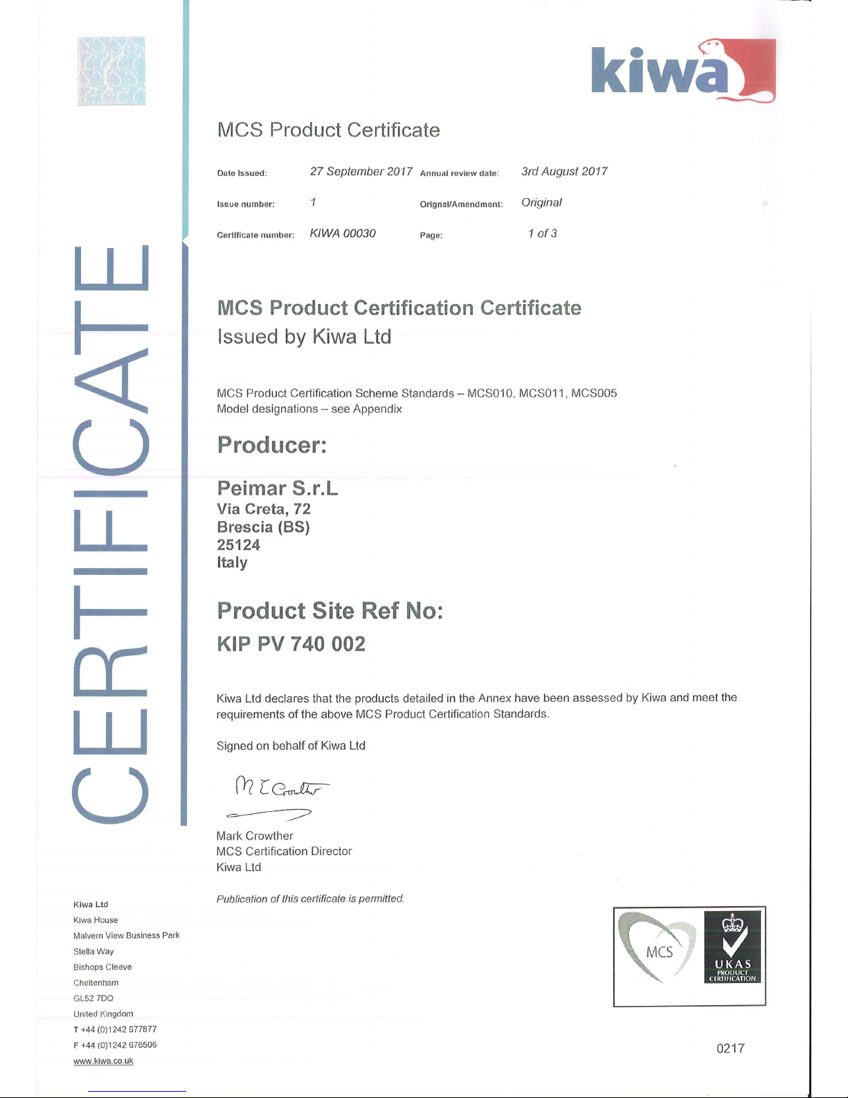
Solar Panel MCS Certificate
Appendix 10.
Adjustable Metal Mount Warranty
Page 3

Plug-In Solar Ltd
289 London Road | Burgess Hill | West Sussex | RH15 9QU
www.pluginsolar.co.uk | [email protected] | 01444 672005 Page 3
TOOL REQUIREMENTS
Please note, this is just a guide, and you may require additional tools than listed here.
8mm Socket Tool
6mm Hex (Allen) Key
13mm Spanner
Drill with S8 Masonry Bit
Voltage Tester
Wire Strippers
Flathead Screwdriver
Phillips Screwdriver
Page 4

Plug-In Solar Ltd
289 London Road | Burgess Hill | West Sussex | RH15 9QU
www.pluginsolar.co.uk | [email protected] | 01444 672005 Page 4
COMPONENT GUIDE
The number of components you receive will depend on the type of kit you have purchased. Please
unpack all your items, and check you have all the correct components based on your Delivery Note.
Solar Panel
Adjustable Metal Frames (two per panel)
Including all fixings (see page 12 for more information)
Micro Inverter (with 2M Cable)
Micro-Inverter End Cap
MC4 Sealing Caps
(If required)
Plug-In Solar Connection Unit
Page 5

Plug-In Solar Ltd
289 London Road | Burgess Hill | West Sussex | RH15 9QU
www.pluginsolar.co.uk | [email protected] | 01444 672005 Page 5
SAFETY INSTRUCTIONS
Before installing or using a Plug-In Solar kit, please read all instructions and cautionary markings in
this document and on the Micro-Inverters and Solar Panels.
The installation of a Plug-In Solar kit shall be carried out by a competent person with sufficient skills
and training to apply safe methods of work, in compliance with G83/2 Engineering
Recommendations.
The installation of a Plug-In Solar kit will be carried out to no lower a standard than that required in
the Manufacturer’s installation instructions, as provided here.
No parameter relating to the electrical connection and subject to type verification certification will
be modified unless previously agreed in writing between the DNO (Distribution Network Operator)
and the Customer.
All electrical installations shall be performed in accordance with local electrical codes.
All appropriate health and safety regulations must be observed and required safety precautions
taken.
Be aware that installation of this equipment includes the risk of electric shock.
Be aware that the body of the Micro-Inverter is the heat sink and can reach a temperature of 80°C.
To reduce risk of burns, do not touch the body of the Micro-Inverter.
DO NOT disconnect the PV module from the Micro-Inverter without first disconnecting the AC
power. !In no circumstances, connect a DC input when an AC connector is unplugged.
DO NOT attempt to repair a Micro-Inverter. If it fails, contact Hoymiles Customer Support to
obtain an RMA number and start the replacement process. Damaging or opening a Micro-Inverter
will void the warranty.
CAUTION! !The external protective earthing conductor is connected to the micro-inverter
protective earthing terminal via an AC connector. !When connecting; connect the AC connectors
first to ensure the micro-inverter earthing then undertake the DC connections. When
disconnecting; disconnect the AC by opening the branch circuit breaker. Whilst maintaining the
protective earthing conductor in the branch circuit breaker, connect to the micro-inverter, then
disconnect the DC inputs. !
You MUST follow the IET Wiring Regulations at all times and consult a professional
electrician if you are in any doubt.
Page 6

Plug-In Solar Ltd
289 London Road | Burgess Hill | West Sussex | RH15 9QU
www.pluginsolar.co.uk | [email protected] | 01444 672005 Page 6
WARNINGS
Never disconnect the DC wire connectors under load. Ensure that no current is
flowing in the DC wires prior to disconnecting. An opaque covering may be used to
cover the module prior to disconnecting the module.
Do not touch any live parts in the system, including the Solar array, when the
system has been connected to the electrical grid.
Prior to installing any of the Micro-Inverters, verify that the utility voltage at the
point of common connection matches the voltage rating on Micro-Inverter label.
Do not mount the Micro-Inverter in a location that allows exposure to direct
sunlight. Allow a minimum of 3/4’’(1.5cm.) between the roof and the bottom of the
Micro-Inverter to allow proper airflow.
Always disconnect AC power before disconnecting the PV module wires from the
Micro-Inverter. The AC connector of the first Micro-Inverter in a branch circuit is
suitable, as a disconnecting means, once the AC branch circuit breaker in the load
center has been opened.
The Micro-Inverter is powered by PV module DC power. Make sure you disconnect
and reconnect the DC connections to watch for the five short flashes.
Page 7

Plug-In Solar Ltd
289 London Road | Burgess Hill | West Sussex | RH15 9QU
www.pluginsolar.co.uk | [email protected] | 01444 672005 Page 7
SOLAR PANEL INSTALLATION
When installing the solar panels included in your Plug-In Solar Kit, you must abide by a number of
safety requirements:
Do not operate solar panels near highly flammable gas !and vapors (e.g. gas tanks, gas stations).
!
Do not install solar panels in enclosed space. !
Do not install solar panels in locations where they may be !submerged in water.
!
Do not use solar panels as a substitute for normal !roofing (solar panels are not watertight).
Do not install solar panels in close proximity to air conditioning !systems.
Do not install solar panels above 4000 m (13120 ft) altitude !above sea level. !
Do not allow any chemical substance (e.g. oil, solvent !etc.) to come into contact with any part of
the solar panels.
The solar panel operating temperature must be between –40 °C to +85 °C (–40 °F to +185 °F).
Prevent solar panel shadowing. Optimal solar irradiation leads to maximum energy output. Install
the solar panels so that they face !the sun.
Avoid shadowing (due to objects such as buildings, !chimneys or trees).
Avoid partial shading (for example through overhead !lines, dirt, snow). !
Ensure you conform to the necessary structural requirements where you are installing the solar
panels. !
Ensure the solar panels are properly fastened to the ground, the roof, or the facade, using the
mounts provided.!
Ensure sufficient rear ventilation of the module.
!
Follow grounding procedures set out in the roof mount installation manual.
Please see the following instructions for further information on how to handle and install your solar
panels.
Refer to the Micro-Inverter installation section of this installation manual for information on how to
wire your solar panels to the Micro-Inverters.
Page 8

Plug-In Solar Ltd
289 London Road | Burgess Hill | West Sussex | RH15 9QU
www.pluginsolar.co.uk | [email protected] | 01444 672005 Page 8
Page 9

Plug-In Solar Ltd
289 London Road | Burgess Hill | West Sussex | RH15 9QU
www.pluginsolar.co.uk | [email protected] | 01444 672005 Page 9
Page 10

Plug-In Solar Ltd
289 London Road | Burgess Hill | West Sussex | RH15 9QU
www.pluginsolar.co.uk | [email protected] | 01444 672005 Page 10
Page 11

Plug-In Solar Ltd
289 London Road | Burgess Hill | West Sussex | RH15 9QU
www.pluginsolar.co.uk | [email protected] | 01444 672005 Page 11
Page 12

Plug-In Solar Ltd
289 London Road | Burgess Hill | West Sussex | RH15 9QU
www.pluginsolar.co.uk | [email protected] | 01444 672005 Page 12
ADJUSTABLE GROUND MOUNT SYSTEM INSTALLATION
Important Notes before the installation of Adjustable Ground Mounts
1. The size of the mounting system (number of mounting triangles) should be specifically
calculated for each individual project, following the specified structural engineering standards
and regulations.
2. A prerequisite for proper application is a solid mounting base that can accommodate the
occurring forces (weight, wind and snow loads). ………………………………………
3. You MUST ballast your mounting system, especially in high wind areas. This can be done with
sandbags or similar (not supplied). For additional fixings to secure your grounds mounts to
concrete/metal or other material please contact us.
4. The installation instructions of the solar panel manufacturers must be adhered to.
5. When installing this product please observe the appropriate health and safety regulations and
take required safety precautions. This may include but is not limited to, gloves and goggles.
Plug-In Solar takes no responsibility for the method by which you choose to install your mounting
system. This is a guide only. Please consult a roofing expert if you are in any doubt on how to
safely and correctly install your system.
Adjustable Ground Mount System Components
Adjustable Metal Mounts
Solar Panel Clamps
SFS Screws
Bolts
Page 13

Plug-In Solar Ltd
289 London Road | Burgess Hill | West Sussex | RH15 9QU
www.pluginsolar.co.uk | [email protected] | 01444 672005 Page 13
Adjustable Ground Mount Installation
1. Open a mounting triangle, and pull adjustable arm upwards. You can choose the angle at
which you install the panels for the best possible efficiency, by adjusting the support arm. You
will need your 13mm Spanner at this stage.
Page 14

Plug-In Solar Ltd
289 London Road | Burgess Hill | West Sussex | RH15 9QU
www.pluginsolar.co.uk | [email protected] | 01444 672005 Page 14
2. Secure the Solar Panels to the Ground Mount system (using the nuts, bolts and SFS screws
provided). You will need your Hex key, Spanner and a drill with a masonry bit at this stage.
3. Continue this process until you have installed all the solar panels. Ensure all screws and
clamps are sufficiently tightened.
4. Remember to ballast your ground mount system accordingly, or use the mounting clips
(available on request) shown below to secure the frames to a concrete base. Please contact us
if you need any further information on the amount of ballast required.
Page 15

Plug-In Solar Ltd
289 London Road | Burgess Hill | West Sussex | RH15 9QU
www.pluginsolar.co.uk | [email protected] | 01444 672005 Page 15
MICRO-INVERTER INSTALLATION
1. System Wiring Diagram
2. Once you have completed installing the Adjustable Metal Mount system, use the SFS (self
drilling) screws provided to affix the Micro-Inverter to the upper arm of the Metal Mounts. See
image below for guidance.
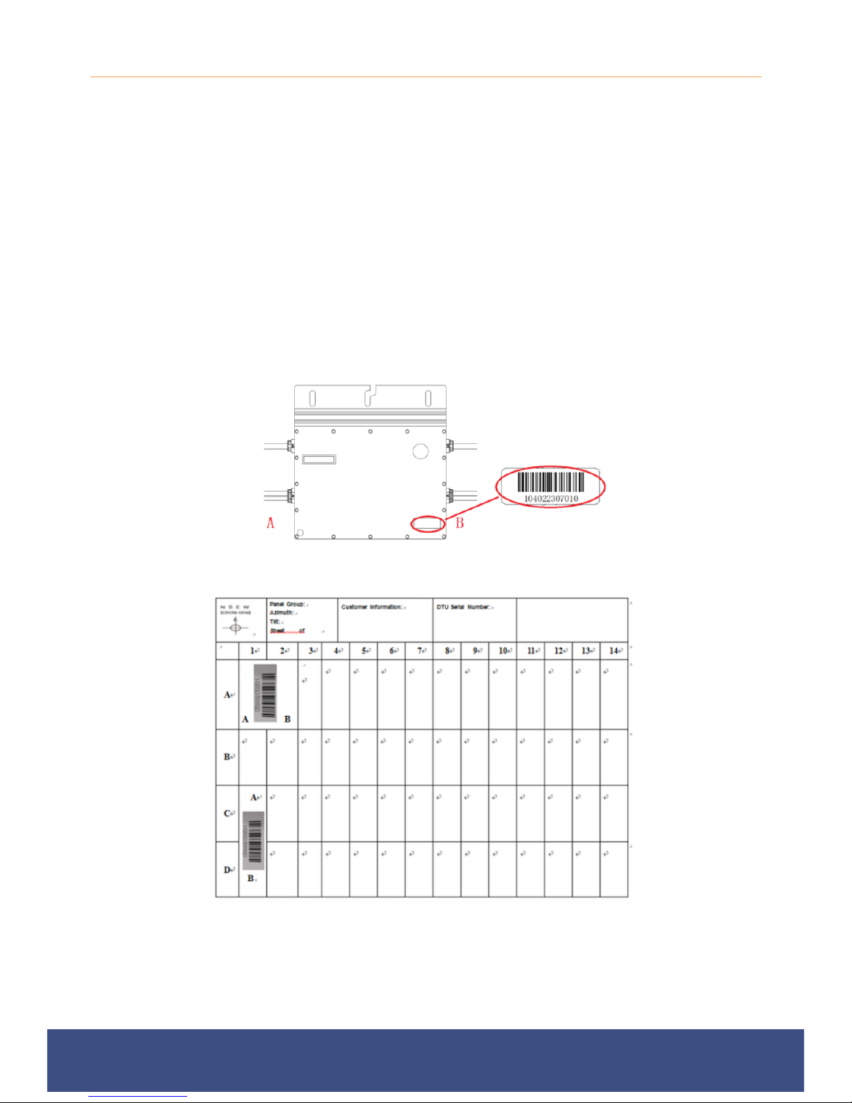
Each Micro-Inverter has serial number labels affixed. Once the micro-inverters are installed, please
peel one label off each micro-inverter and stick them to the warranty card (please refer to the
‘Completing Your Warranty Card’ section of this installation manual for more information).
Page 16

Plug-In Solar Ltd
289 London Road | Burgess Hill | West Sussex | RH15 9QU
www.pluginsolar.co.uk | [email protected] | 01444 672005 Page 16
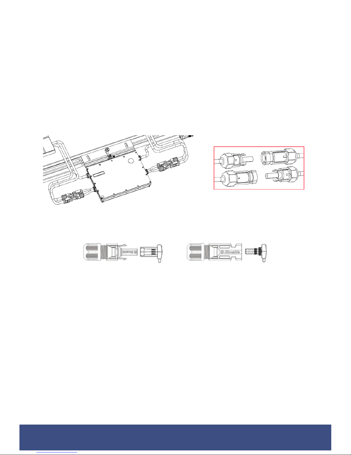
3. Connect the Micro-Inverters to the AC Bus Trunk Cable
Plug the AC connector of the first Micro-Inverter into the connector of the next Micro-Inverter, and
so forth, to form a continuous AC branch circuit. Do this for each Micro-Inverter in your system.
Ensure a click is heard as connectors engage. Ensure that all connections are properly closed.
WARNIING: Do NOT exceed a maximum of (5) five Micro-Inverters in an AC branch circuit when
using the Plug-In Solar System.
Install the End Cap on the open AC connector of the last Micro-Inverter in the AC branch circuit.
Ensure a click is heard as connectors engage. Ensure that all connections are properly closed.
Page 17
Plug-In Solar Ltd
289 London Road | Burgess Hill | West Sussex | RH15 9QU
www.pluginsolar.co.uk | [email protected] | 01444 672005 Page 17
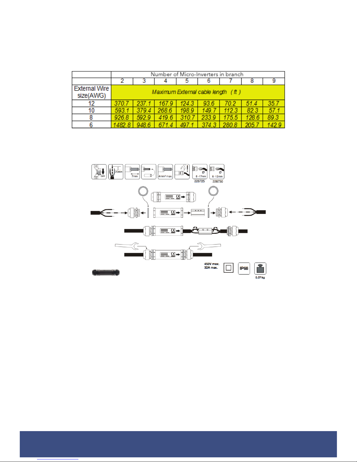
4. Connect Micro Inverters to Solar Panels (PV Modules)
Connect each Solar Panel to the Micro-Inverter DC cables to feed PV power into the Micro
inverter, following the polarity direction marked on each Micro inverter. Ensure a click is heard as
connectors engage.
When plugging in the DC cables, the Micro-Inverter should immediately blink green three times.
This will happen as soon as the cables are plugged in and will show that the Micro-Inverter is
functioning correctly. This entire check function will start and end within 5 seconds of plugging in
the unit, so pay careful attention to these lights when connecting the DC cables.
WARNING: Ensure that all AC and DC wiring is correct. Ensure that none of the AC and DC wires
are pinched or damaged. Ensure that all connections are properly closed.
WARNING: If you are installing an odd number of Solar panels, ensure you use the MC4 sealing
caps provided with your kit to seal the exposed MC4 connectors on the Micro-Inverter.
Page 18
Plug-In Solar Ltd
289 London Road | Burgess Hill | West Sussex | RH15 9QU
www.pluginsolar.co.uk | [email protected] | 01444 672005 Page 18
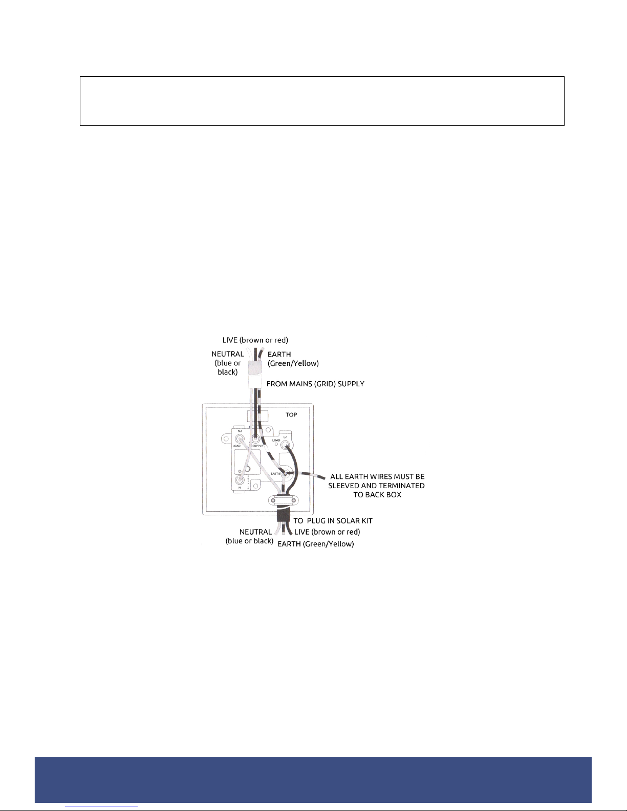
5. If you need to extend the length of AC Bus Trunk Cable, we can supply extra lengths on
request. If you provide your own cable please be sure to use the correct cable wire size (AWG)
depending on distance of the last Micro-Inverter to the connection point and the number of
Micro-Inverters in the branch, as shown in the table below. Please be aware, the longer the
cable run, the greater the power loss.
Follow the instructions outlined below to connect the APS AC Bus Trunk Cable to your extension
cable, using a connection box, or similar (supplied upon request).
Page 19

Plug-In Solar Ltd
289 London Road | Burgess Hill | West Sussex | RH15 9QU
www.pluginsolar.co.uk | [email protected] | 01444 672005 Page 19
WIRING THE SOLAR TO THE EXISITING MAINS CIRCUIT
IMPORTANT SAFETY INFORMATION – FOR YOUR PROTECTION
Before installation please read these instructions carefully and use the Plug-In Solar Connection Unit in
accordance with these safety wiring instructions.
In older houses, you may find a variety of old fuse boxes where the mains supply comes in. You may also
have wiring and fittings of an older style. These may not be up to the standard required today. If this is the
case, have it all checked and tested by a professional electrician BEFORE carrying out any work on it.
Some old installations may now be dangerous.
Electricity is dangerous. Always disconnect from mains supply before any inspection or repair to equipment.
Safety must always be given top priority. Do not allow children to tamper with electrical devices.
ALWAYS FOLLOW THE IET WIRING REGULATIONS.
You must NOT install the Plug-In Solar Connection Unit in the following locations as set out by Part P:
(a) within a room containing a bath or shower, the space surrounding a bath tap or shower head,
where the space extends —
(i) vertically from the finished floor level to —
(aa) a height of 2.25 metres; or
(bb) the position of the shower head where it is attached to a wall or ceiling at a point
higher than 2.25 metres from that level; and
(ii) horizontally —
(aa) where there is a bath tub or shower tray, from the edge of the bathtub or shower
tray to a distance of 0.6 metres; or
(bb) where there is no bath tub or shower tray, from the centre point of the shower
head where it is attached to the wall or ceiling to a distance of 1.2 metres; or
(b) a room containing a swimming pool or sauna heater.
As an additional precaution, wear rubber-soled shoes. This will provide a measure of insulation between you
and the ground!
IF YOU ARE NOT ABSOLUTELY CERTAIN ABOUT ANY ASPECT OF ELECTRICAL WORK, SEEK PROFESSIONAL ADVICE
1.1. Switch off the power and remove the fuse for the relevant circuit before carrying out any
work, or inspecting, either it, or the appliances connected to it. Never inspect, or carry out work
on, any part of the system with the power on. Make sure that power cannot be inadvertently
restored by someone else.
1.2. Use a voltage tester to check the power to the wires or connections are off before touching
them.
Page 20
Plug-In Solar Ltd
289 London Road | Burgess Hill | West Sussex | RH15 9QU
www.pluginsolar.co.uk | [email protected] | 01444 672005 Page 20
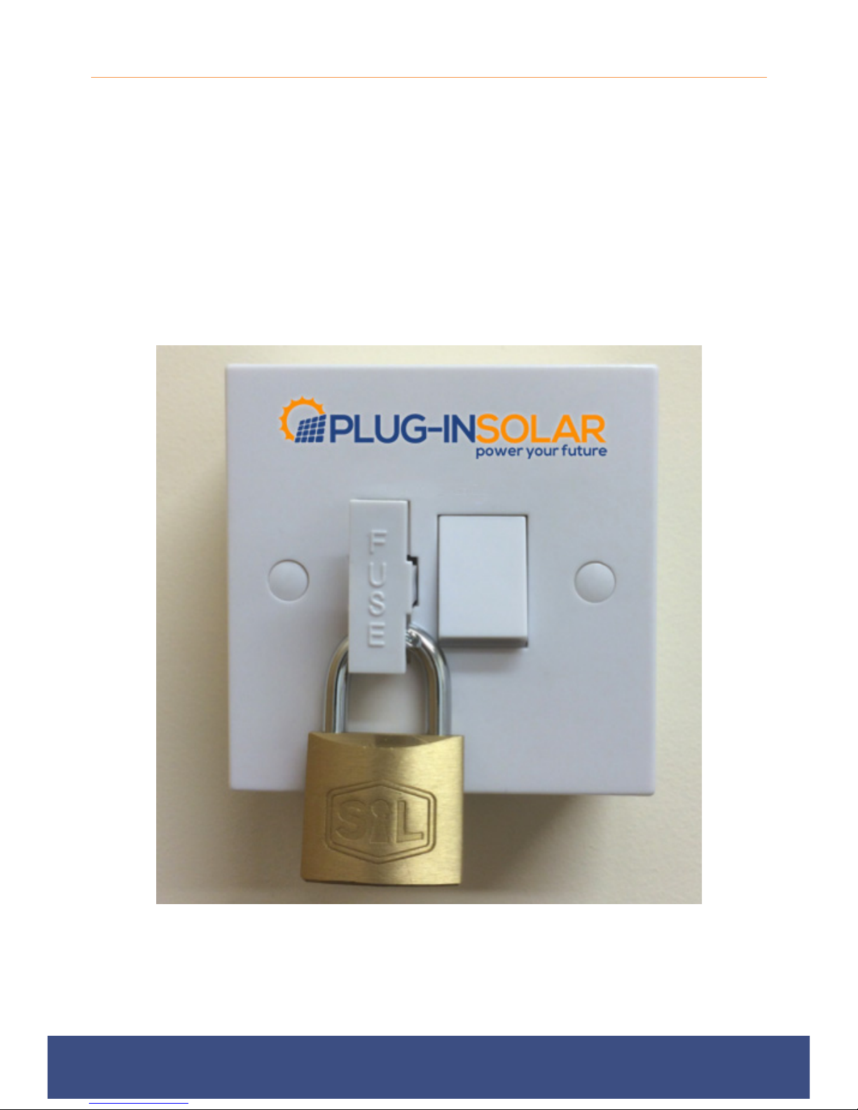
1.3. Once the power is disconnected, wire the Plug-In Solar Connection Unit using the following
instructions.
Wire Identification (if in doubt consult a qualified electrician)
EARTH – Green and Yellow Sleeving
LIVE – Red or Brown
NEUTRAL – Blue or Black
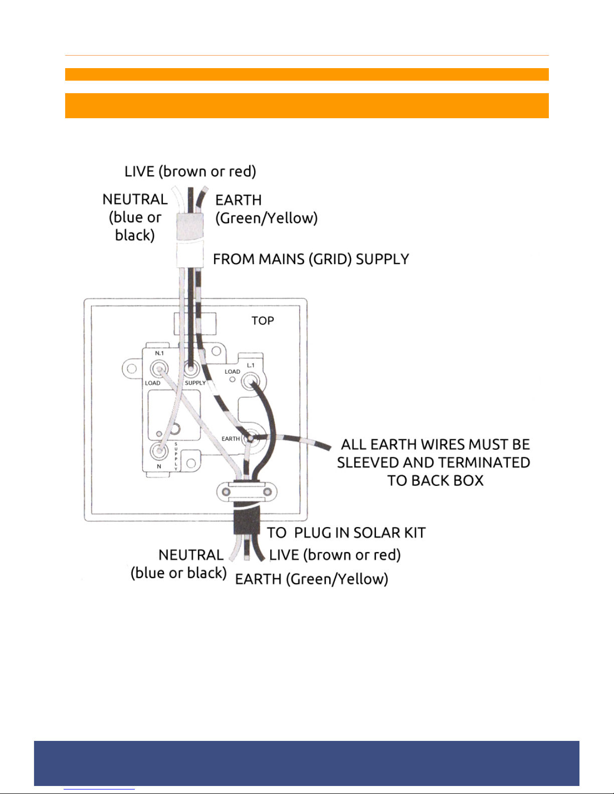
a) If using the Plug-In Solar Connection Unit to replace an old socket (or similar), note the cable
connections and wire up the Plug-In Solar Connection Unit the same way as the replaced item, with
earthing as stated in these instructions.
b) Route the cable through the appropriate entry point of the mounting box (this is usually at the rear).
c) Cables should be prepared so sufficient conductor length reaches the terminals. Strip the ends of
the individual conductors so that an adequate length enters the terminals.
d) Carefully arrange the wiring to lie along the edges of the product or box, keeping the central area
clear.
e) Wire the Plug-In Solar Connection Unit using the following diagram (a larger version can be found in
Appendix 1):
f) When connecting the Plug-In Solar Connection Unit ensure that only the bare end of the wire enters
the terminal, and no bare wires are visible. Always tighten the terminal screws, but don’t over
tighten. An earth connection should always be made between the mounting box earth terminal and
the fused connection unit terminal. If the earth wire is bare, it must be sleeved with appropriate
green/yellow sleeving.
g) If you are in any doubt about connecting this product consult a qualified electrician.
1.4. Wiring insulation tests should be completed to avoid misleading instrument readings and
possible internal damage to the unit. Check your work thoroughly before restoring power to the
circuit. If you are not certain, seek professional advice.
1.5. Once power has been restored, after around a two minute initialisation time, your Plug-In
Solar kit will be feeding FREE electricity into your mains circuit.
Page 21
Plug-In Solar Ltd
289 London Road | Burgess Hill | West Sussex | RH15 9QU
www.pluginsolar.co.uk | [email protected] | 01444 672005 Page 21
ISOLATION/ISOLATOR REQUIREMENTS
Under G83/2 requirements, it must be possible to isolate a Plug-In Solar kit from the from the
DNO’s Distribution System, using a Double Pole Isolator. This is the function of the Plug-In Solar
Connection Unit.
The Plug-In Solar Connection Unit, is a double pole Switched Fused Connection Unit, that adheres
to British Standard BS1363-4, and offers on load isolation from the grid.
G83/2 regulations also state that the Plug-In Solar Connection Unit is lockable in the OFF position
only. This ensures isolation under maintenance. The Fuse carrier of the Plug-In Solar Connection
Unit can be locked open (the OFF position), as per the image below, in order to meet this
requirement (padlock not provided).
Page 22
Plug-In Solar Ltd
289 London Road | Burgess Hill | West Sussex | RH15 9QU
www.pluginsolar.co.uk | [email protected] | 01444 672005 Page 22
PLACING WARNING LABELS
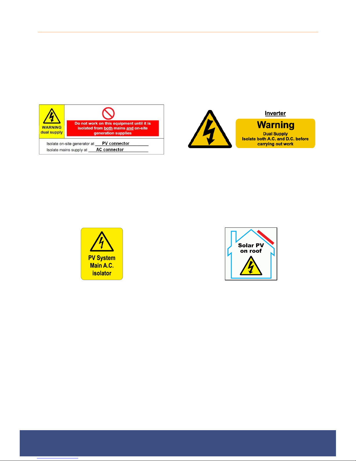
When installing a Plug-In Solar kit you must place labelling at the Plug-In Solar Connection
Unit, Existing Consumer Unit and at all points of isolation between the Plug-In Solar
Connection Unit and the Solar Panels within your premises. This is to indicate the presence
of a Small Scale Embedded Generation installation (SSEG). The labelling should fixed in place to
ensure that it remains legible and secure for the lifetime of the installation. The following labels must
be used and have been provided with your Plug-In Solar kit.
Dual supply labelling should be placed at the
Plug-In Solar Connection Unit between the
PV system and Existing Consumer Unit to
indicate the presence of on-site generation
and indicating the position of the main A.C
switch disconnector.
An APS Inverter should be labelled stating
"Inverter - isolate A.C. and D.C. before carrying
out work". The Micro-Inverters also have this
warning label as standard.
An AC isolator Label should be placed next
to the Plug-In Solar Connection Unit and all
other AC switches/disconnects (if
applicable). ON and OFF positions should
be clearly labelled.
To ensure the Fire and Rescue Service are
aware that Solar is installed on the roof the
following sign shall also be fitted next to the
existing consumer unit in the building. You do
not need this label for Ground Mount systems.
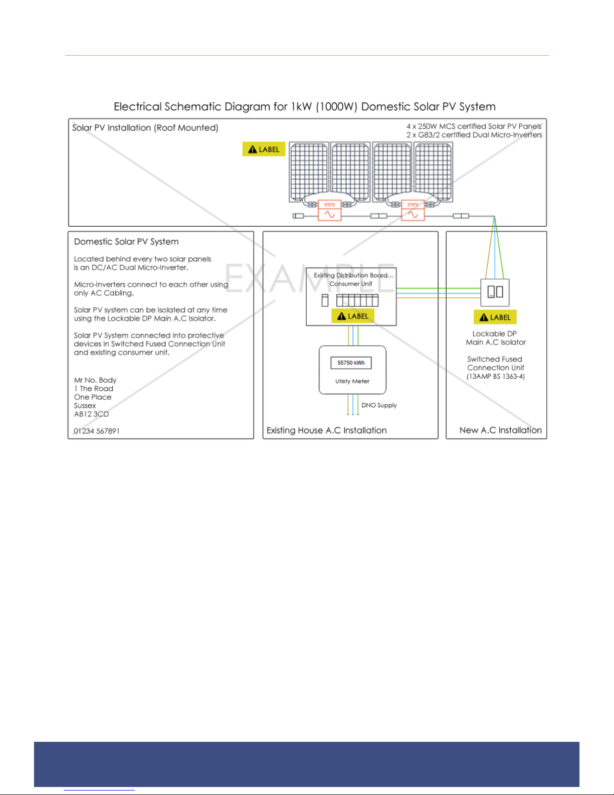
In addition to this safety labelling, you must also display an electrical schematic diagram next to the
existing consumer unit in the property. You will have been provided with an electrical schematic
diagram relevant to your kit, but can see an example in Appendix 3. Please note the diagram in
Appendix 3 is non-prescriptive and is for illustrative purposes only.
Page 23

Plug-In Solar Ltd
289 London Road | Burgess Hill | West Sussex | RH15 9QU
www.pluginsolar.co.uk | [email protected] | 01444 672005 Page 23
INSPECTING AND TESTING YOUR PLUG-IN SOLAR INSTALLATION
As part of the G83/2 on-site commissioning tests you shall carry out a functional check of the loss
of mains protection, for example by removing the supply to the Plug-In Solar kit during operation
and checking that the Plug-In Solar Connection Unit operates to disconnect the Plug-In Solar Kit
from the DNO’s Distribution System.
In the UK the installation of a Plug-In Solar Kit is considered non-notifiable electrical work under
Part P of the Building Regulations 2013, as it is an alteration to an existing installation (the mains
grid).
“Regulation 12(6A) sets out electrical installation work that is notifiable. All other electrical
installation work is not notifiable – namely additions and alterations to existing installations outside
special locations, and replacements, repairs and maintenance anywhere.”
Installation of a non-notifiable Plug-In Solar kit should still be designed, installed, inspected, tested
and certificated in accordance with BS 7671.
For more information on how to do this, you can find a copy of Part P building regulations here:
http://www.planningportal.gov.uk/uploads/br/BR_PDF_AD_P_2013.pdf
Page 24
Plug-In Solar Ltd
289 London Road | Burgess Hill | West Sussex | RH15 9QU
www.pluginsolar.co.uk | [email protected] | 01444 672005 Page 24
COMMISSIONING YOUR PLUG-IN SOLAR INSTALLATION
Once you have installed, inspected and tested your Plug-In Solar kit, it is a requirement that you
complete and return a G83/2 SSEG Installation Commissioning Confirmation Form to your District
Network Operator (DNO) within 28 days.
Distribution Network Operators (DNOs) own and operate the distribution network of towers and
cables that bring electricity from the national transmission network to homes and businesses. They
don’t sell electricity to consumers, this is done by the electricity suppliers. Informing the DNO of
your installation allows them to manage the grid more effectively.
There are 9 different DNO’s across the UK, so you must make sure you submit your form to the
correct DNO in your area. You can find your DNO by entering your postcode using this website:
https://www.ssepd.co.uk/Whoismynetworkoperator/
Once you have identified your DNO you must download a G83/2 SSEG Installation Commissioning
Confirmation Form from their website (or request that they e-mail one to you).
Completing G83/2 SSEG Installation Commissioning Confirmation Form
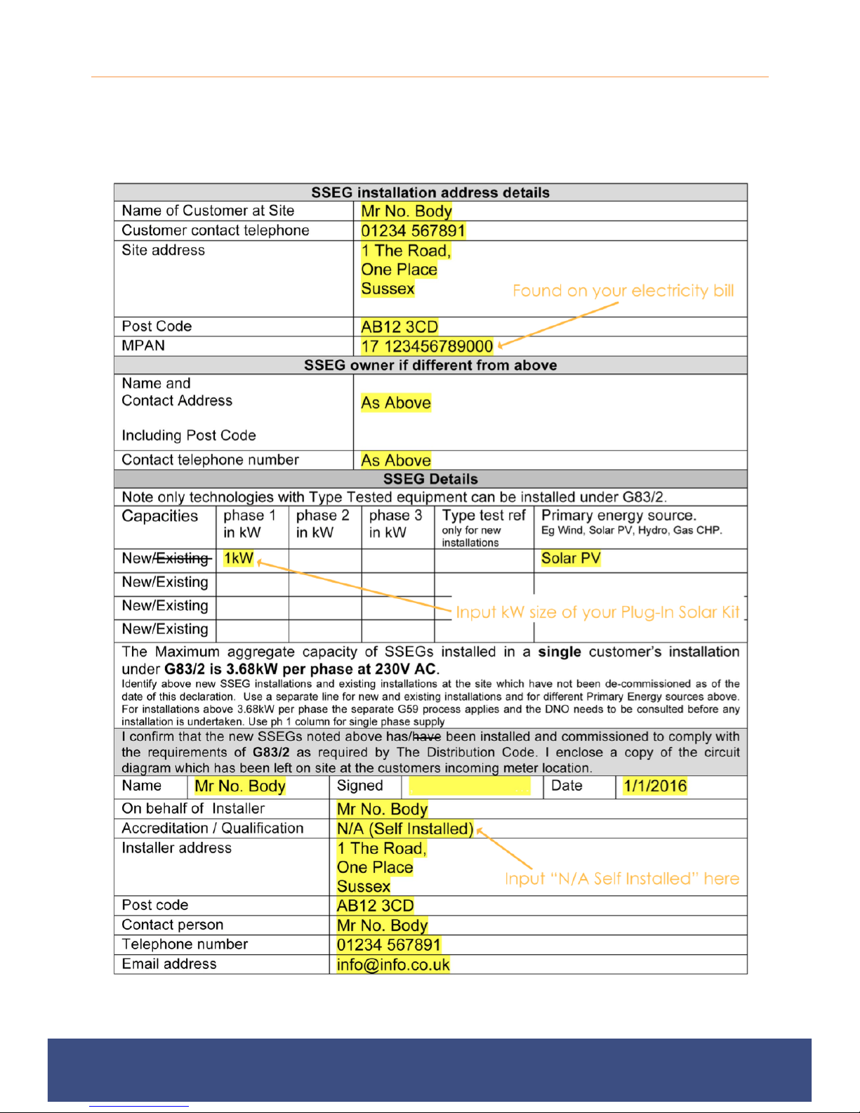
An example G83/2 Commissioning Confirmation Form can be found in Appendix 2 of this
Installation Manual. Please note G83/2 forms differ between DNO’s, this is an example only.
The G83/2 SSEG Installation Commissioning Confirmation Form is relatively self-explanatory,
however there are a number of sections that you must complete correctly:
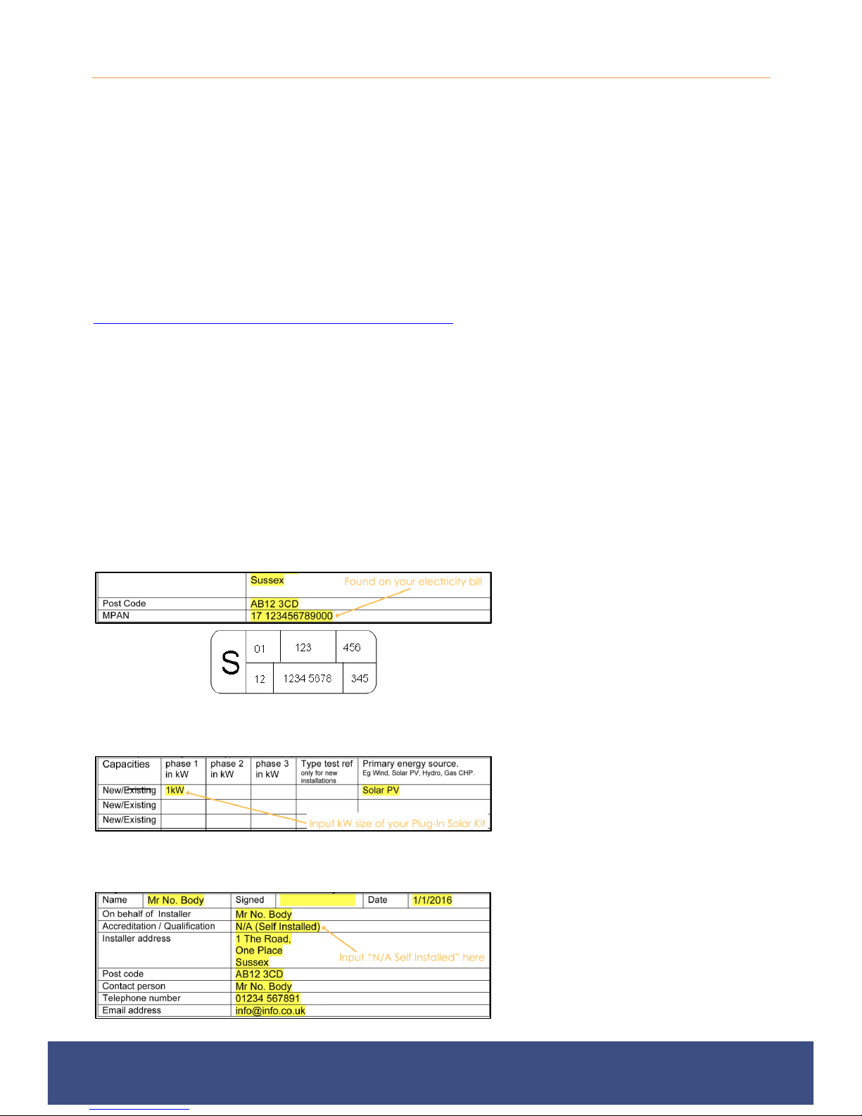
SSEG Installation Address Details Section
A Meter Point Administration Number, also
(MPAN), is a 21-digit reference used in the
UK to uniquely identify electricity supply
points. You must correctly fill in your own
MPAN in this section of the form.
Your MPAN can be found on your electricity
bill and often looks like the image on the left.
SSEG Details Section
Within the SSEG Details section of the form,
fill in the details of your installation. The
capacity will be the size of the Plug-In Solar
kit you purchased, i.e. 1kW. The Primary
Energy Source must always be filled as ‘Solar
PV’. If you have any existing SSEG’s (e.g.
wind/solar) you must also declare these here.
SSEG Installer Details Section
As Plug-In Solar kits are DIY, self installed
solar systems you should complete this
section as the installer. In the
Accreditation/Qualification section you should
fill this in as ‘N/A (Self-Installed)’, unless you
have an appropriate accreditation. This
section of the form also needs to be signed.
Page 25

Plug-In Solar Ltd
289 London Road | Burgess Hill | West Sussex | RH15 9QU
www.pluginsolar.co.uk | [email protected] | 01444 672005 Page 25
Along with the completed G83/2 SSEG Installation Commissioning Confirmation Form, you must
also supply the DNO with the following:
1. An electrical schematic diagram for your installation (A relevant electrical schematic diagram will be
provided with your Plug-In Solar Kit). An example can be seen in Appendix 3.
2. A copy of the G83/2 SSEG Test Report Certificate for the Micro-Inverters (This can be found in
Appendix 7)
3. A photograph of your existing electricity meter (be sure to include the make and model of the meter)
Email/Fax/Post the information above to your DNO using the contact supplied on the
Commissioning Form. Do not send it to Plug-In Solar, we cannot apply to the DNO on your behalf.
When the DNO has received your form and it has been processed, you will get a confirmation
email/letter to say it has been accepted.
Notifying the DNO of changes to a Plug-In Solar kit
If during the lifetime of the Plug-In Solar kit it is necessary to replace a major component of the
Plug-In Solar kit, it is only necessary to notify the DNO if the operating characteristics of the Plug-In
Solar kit or the Plug-In Solar Connection Unit have been altered when compared against the unit
that was originally commissioned.
Notifying the DNO of the decommissioning of a Plug-In Solar kit
In the event that a Plug-In Solar kit is to be decommissioned and will no longer operate as a
source of electrical energy in parallel with the DNO’s Distribution System, you must notify the DNO
by completing a G83/2 SSEG Decommissioning Confirmation Form. Please contact your DNO for
a copy of this form.
Page 26
Plug-In Solar Ltd
289 London Road | Burgess Hill | West Sussex | RH15 9QU
www.pluginsolar.co.uk | [email protected] | 01444 672005 Page 26
COMPLETING YOUR WARRANTY CARD
In order to fulfill the requirements of the manufacturers, you must complete Warranty Cards for the
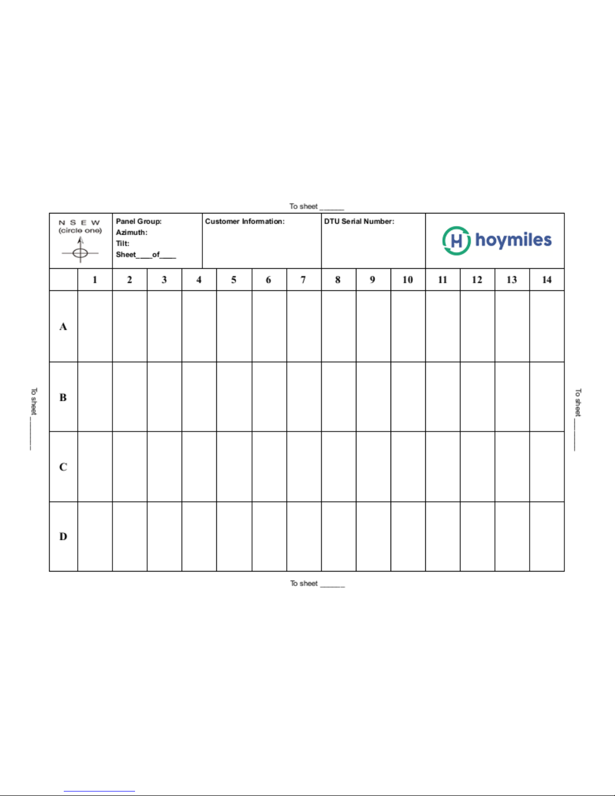
Micro-Inverters, which provide system information and installation maps to Hoymiles. A Warranty
Card can be found in Appendix 6.
Each Micro-Inverter has serial number labels affixed. Once the inverters are installed, please peel
one of the labels off each Micro-Inverter and affix them to the warranty card.
Fill in the warranty card with each of the labels according to the layout on the roof/ground. The DC
inputs are identified by A and B. The left input is A and the right one is B, as shown below.
If you have a purchased an online monitoring system, please refer to the User Manual provided
with this guide for detailed instructions on how to install it correctly, and use these installation
maps to set it up.
Page 27
Plug-In Solar Ltd
289 London Road | Burgess Hill | West Sussex | RH15 9QU
www.pluginsolar.co.uk | [email protected] | 01444 672005 Page 27
COMPLETING YOUR SOLAR INSTALLTION
Page 28
Plug-In Solar Ltd
289 London Road | Burgess Hill | West Sussex | RH15 9QU
www.pluginsolar.co.uk | [email protected] | 01444 672005 Page 28
APPENDIX 1. PLUG-IN SOLAR CONNECTION UNIT – WIRING DIAGRAM
ALWAYS FOLLOW THE IET WIRING REGULATIONS
IF YOU ARE NOT ABSOLUTELY CERTAIN ABOUT ANY ASPECT OF ELECTRICAL WORK,
SEEK PROFESSIONAL ADVICE
Page 29
Plug-In Solar Ltd
289 London Road | Burgess Hill | West Sussex | RH15 9QU
www.pluginsolar.co.uk | [email protected] | 01444 672005 Page 29
APPENDIX 2. EXAMPLE G83/2 COMMISSIONING CONFIRMATION FORM
Please note, G83/2 SSEG Installation Commissioning Confirmation Forms differ between DNO’s
and this may not look like the form you receive. This is non-prescriptive and is for illustrative
purposes only.
Page 30
Plug-In Solar Ltd
289 London Road | Burgess Hill | West Sussex | RH15 9QU
www.pluginsolar.co.uk | [email protected] | 01444 672005 Page 30
APPENDIX 3. EXAMPLE ELECTRICAL SCHEMATIC DIAGRAM
This is non-prescriptive and is for illustrative purposes only.
Page 31

Plug-In Solar Ltd
289 London Road | Burgess Hill | West Sussex | RH15 9QU
www.pluginsolar.co.uk | [email protected] | 01444 672005 Page 31
APPENDIX 4. TROUBLESHOOTING MICRO-INVERTERS
Status Indications and Error Reporting
Startup LED
When DC power is first applied to the Micro-Inverter: Five short green blinks indicate a successful
Micro-Inverter startup.
Operation LED
Flashing Slow Green (4s gap) - Producing power and communicating with DTU
Flashing Fast Green (2s gap) – Producing power and not communicating with ECU
Flashing Red – Not producing power (AC Grid Invalid – Voltage or Frequency out of range).
GFDI Error
A solid red LED indicates the Micro-Inverter has detected a ground fault (GFDI) error in the PV
system. Unless the GFDI error has been cleared, the LED will remain red and the ECU will keep
reporting the fault.
After the ground fault error is fixed, follow the instructions in the ECU Installation and Operation
Manual to clear this GFDI error reporting.
Non-Operating Micro-Inverters
1. To troubleshoot a non-operating Micro-Inverter, follow the steps below in order:
2. Check the connection to the utility grid. Verify utility power is present at the inverter in question
by removing AC, then DC power. Never disconnect the DC wires while the MicroInverter is producing power. Re-connect the DC module connectors and watch for three
short green LED flashes. !
3. Check the AC branch circuit interconnection between all the Micro-Inverters. Verify each micro-
inverter is energised by the utility grid as described in the previous step. !
4. Make sure that any AC breakers are functioning properly and are closed.
5. Check the DC connections between the Micro-Inverter and the PV module. !
6. If the problem persists, please contact Hoymiles customer support on (+44) 028 2076 9210 or
email [email protected]. DO NOT attempt to repair the Micro-Inverter. If
troubleshooting methods fail, please return the Micro-Inverter to your distributor for
replacement. !
Page 32
© 2018
Hoymiles Converter Technology Co.,Ltd
Warranty Regulations and Liability
1. Warranty Period
Hoymiles products are
designed to withstand normal operating conditions when used for its originally
intended
purpose in compliance with the
system. The Hoymiles
limited warranty (“Limited Warranty”) covers defects in
materials of the Hoymiles
products (
extended warranty as follows which starts from the shipping date.
Model
MI-250
MI-300
MI-500
MI-600
MI-700
MI-1000
MI-1200
DTU
Note:
Additional fee (based on FOB price) for extended warranty period: 20% for 8 years, or
30% for 13 years.
During the Warranty Period,
if Hoymiles establishes, through inspection, the existence of a defect that
covered by the Limited Warranty,
1) R
epair or replace the Defective Product free of charge, or
2) I
ssue a credit or refund for the Defective
value at the time the Warranty Holder notifies Hoymiles of the defect, as determined by Hoymiles.
If Hoymiles elects to repair or replace the Defective Product, Hoymiles will, at its option, use
reconditioned parts in repairing or replacing the Defective Product. Hoymiles reserves the right to use
parts or products of original or improved design in the repair or replacement of Defective Product. If
Hoymiles repairs or replaces a Defect
replacement product for the remainder of the original Warranty Period or ninety (90) days from the date
of Hoymiles’
return shipment of the repaired or replacement product, whichever is later.
Hoymiles
User Manual supplied with the originally shipped
“Defective Product”). Hoymiles provide
both default warranty and
Standard (e
xtended
12(20/25)
12(20/25)
12(20/25)
12(20/25)
12(20/25)
12(20/25)
12(20/25)
2
Hoymiles will, at its option, either
Product to the Warranty Holder in an amount up to its actual
ive Product, the Limited Warranty continues on the repaired or
workmanship and
)
new and/ o r
Page 33

© 2018
Hoymiles Converter Technology Co.,Ltd
2. Limited Liability
The Limited Warranty covers both parts and labor necessary to repair the Defective, but does not
include labor costs related to un-
installing the Defective Product or
replacement product. The Limited
product from Hoymiles, via a non
-
does not cover, and Hoymiles
will not be responsible for, shipping
mishandling by the freight carrier and any such damage is
The Limited Warranty
does not apply to, and
damage to any Hoymiles product
:
1) That has been
misused, neglected, tampered with,
or externally;
2) N
ormal appearance wear out, including discolor and scratch
3) T
he defective has no impact on the
4) That has been
improperly installed, operated, handled or used, including use under conditions for
which
the product was not designed, use in an unsuitable environment, or use in a manner
the Hoymiles
User Manual or applicable laws or regulations;
5) That has been
subjected to fire, water, generalized corrosion, biological infestations, or
that creates operating conditions beyond the maximum or minimum limits
product
specifications, including high input voltage from
6)T
hat has been subjected to incidental or
components of the solar system; or
7)If the original
identification markings (including trademark or serial number) of such
been defaced, altered, or removed.
installation or troubleshooting of the customer's electrical systems. T
extend beyond the original cost of the
re-
installing the repaired or
Warranty also covers the
costs of shipping repaired or replacement
expedited freight carrier selected by
Hoymiles.
damage or damage cau
the responsibility of the freight carrier.
Hoymiles
will not be responsible for, any defect in or
altered, or otherwise damaged, either internally
;
power generation, including LED
indicator
listed in the
generators or lightning strikes;
consequential
damage caused by defects of other
The Limited Warranty does not cover costs related to
he
Limited Warranty does not
Hoymiles product.
Th e Lim ited Warranty
sed by
failure;
contrary to
in put vol tage
Hoymiles
product have
the removal,
Page 34

© 2018
Hoymiles Converter Technology Co.,Ltd
3. RMA & Replacement
To obtain repair or replacement service
you must
comply with the following policy
•
All Defective Product must be returned with a Return Merchandise Authorization
which customer must request from
should contact Hoymiles
technical support
while the Hoymiles products
in the field, since many problems can be solved in the field.
• If in-
field troubleshooting does not solve the problem, Customer may request the
following information:
- Proof-of-
purchase of the Defective Product in the form of (1) the dated
from the original purchase of the product at point of sale to
dealer invoice or purchase receipt showing
or (3) the dated invoice or
-
Model number of the Defective Product
-
Serial number of the Defective Product
-
Detailed description of the defect
-
Shipping address for return of the
• Upon issuance of the RMA,
Hoymiles
Hoymiles product is installed.
• All Defective Product authorized for return must be returned in the original shipping
ot
her packaging that is equally protective of the product
•
The returned Defective Product must not have been disassembled or modified without
written authorization of
Hoymiles.
•
If defective device is replaced by a distributor according to warranty
compensate labor costs to related distributor by USD50 for 1st unit, USD25 for 2nd unit and USD25
for 3rd unit, total compensation for one residential system less than 30
• If the allegedly
faulty microinverter is found by Hoymiles to be ineligible for exchange under this
policy, the compensation payment will not be made and the
the repair of the unit. In order to receive the compensation payment, th
provide proof of a valid warranty for the microinverter, a correctly issued and fully completed
invoice.
, credit or refund (as applicable)
under this Limited Warranty,
and procedure:
Hoymiles. Before requesting the
RMA, however
re pr esentative
to evaluate and troubleshoot the problem
the end user, or (2) the dated
original equipment manufacturer (
purchase receipt showing the product exchanged under warranty.
repaired or replacement product
will ship the replacement unit to the address where the
.
conditions, Hoymiles will
kW
distributor/installer
e
distributor/installer
Number (RMA)
, the customer
RMA number, with
purchase receipt
OEM) status,
container or
the prior
up to USD150.
will be charged for
must
Page 35

© 2018
Hoymiles Converter Technology Co.,Ltd
4. Limited Warranty
THE LIMITED WARRANTY IS THE SOLE AND EXCLUSIVE WARRANTY GIVEN BY
PERMITTE
D BY LAW, IS MADE EXPRESSLY IN LIEU OF ALL OTHERWARRANTIES, EXPRESS OR IMPLIED,
STATUTORY OR OTHERWISE, INCLUDING, WITHOUT LIMITATION, WARRANTIES OF TITLE, QUALITY,
MERCHANTABILITY, FITNESSFOR A PARTICULAR PURPOSE OR NON
AS TO TH
EACCURACY, SUFFICIENCY OR SUITABILITY OF ANY TECHNICAL OR OTHER
INFORMATIONPROVIDED IN MANUALS OR OTHER DOCUMENTATION. IN NO EVENT WILL
BELIABLE FOR ANY SPECIAL, DIRECT, INDIRECT, INCIDENTAL OR CONSEQUENTIALDAMAGES,
LOSSES, COSTS OR EXPENSES HOWEV
WITHOUT LIMITATION ANY ECONOMIC LOSSES OF ANY KIND, ANYLOSS OR DAMAGE TO PROPERTY,
OR ANY PERSONAL INJURY.
To the extent any implied warranties are required under applicable law to apply to the
products
, such implied warranties shall be limited in duration to theWarranty Period, to the extent
permitted by applicable law. Some
or on the duration of animplied warranty or on the li
damages,so the above limitation(s) or exclusion(s) may not apply. This Limited Warranty gives the
Warranty Holder
specific legal rights, and the
region to region.
Hoymiles Converter Technology Co., Ltd
No.18 Kangjing Road, Hangzhou 310015, China
Tel: +86 571 28056101
Fax:+86 571 28056137
E-Mail:[email protected]
http://www.hoymiles.com/
HOYMILES
-
INFRINGEMENT OR WARRANTIES
ER ARISING, WHETHER IN CONTRACTOR TORT, INCLUDING
regions
do not allow limitations or exclusions on implied warranties
mitation or exclusion of incidental or consequential
Warranty Holder
may have other rights that may varyfrom
AND, WHERE
HOYMILES
Hoymiles
Page 36
22
Page 37
1
G83/2 Appendix 4 Type Verification Test Report
Type Approval and manufacturer/supplier declaration of compliance with the requirements
of Engineering Recommendation G83/2.
SSEG Type reference number
MI-600
SSEG Type
Photovoltaic Microinverter
System Supplier name
Hoymiles Converter Technology Co.,Ltd
Address
3rd Floor,Building 11,18#Kangjing road,KangQiao
Industrial Zone,HangZhou City,Zhejiang Province
Tel
+86 571 28056101
Fax
+86 571 28056137
E:mail
Web site
www.hoymiles.com
Maximum
rated
capacity,
use
separate
sheet if
more than
one
connection
option.
Connection Option
0.6
kW single phase, single, split or three phase system
NA
kW three phase
NA
kW two phases in three phase system
NA
kW two phases split phase system
SSEG manufacturer/supplier declaration
I certify on behalf of the company named above as a manufacturer/supplier of Small Scale
Embedded Generators, that all products manufactured/supplied by the company with the
above SSEG Type reference number will be manufactured and tested to ensure that they
perform as stated in this Type Verification Test Report, prior to shipment to site and that no
site modifications are required to ensure that the product meets all the requirements of
G83/2.
Signed
On behalf of
Hoymiles Converter Technology
Co.,Ltd
Note that testing can be done by the manufacturer of an individual component, by an
external test house, or by the supplier of the complete system, or any combination of them
as appropriate.
Where parts of the testing are carried out by persons or organisations other than the
supplier then the supplier shall keep copies of all test records and results supplied to them
to verify that the testing has been carried out by people with sufficient technical competency
to carry out the tests.
Page 38
2
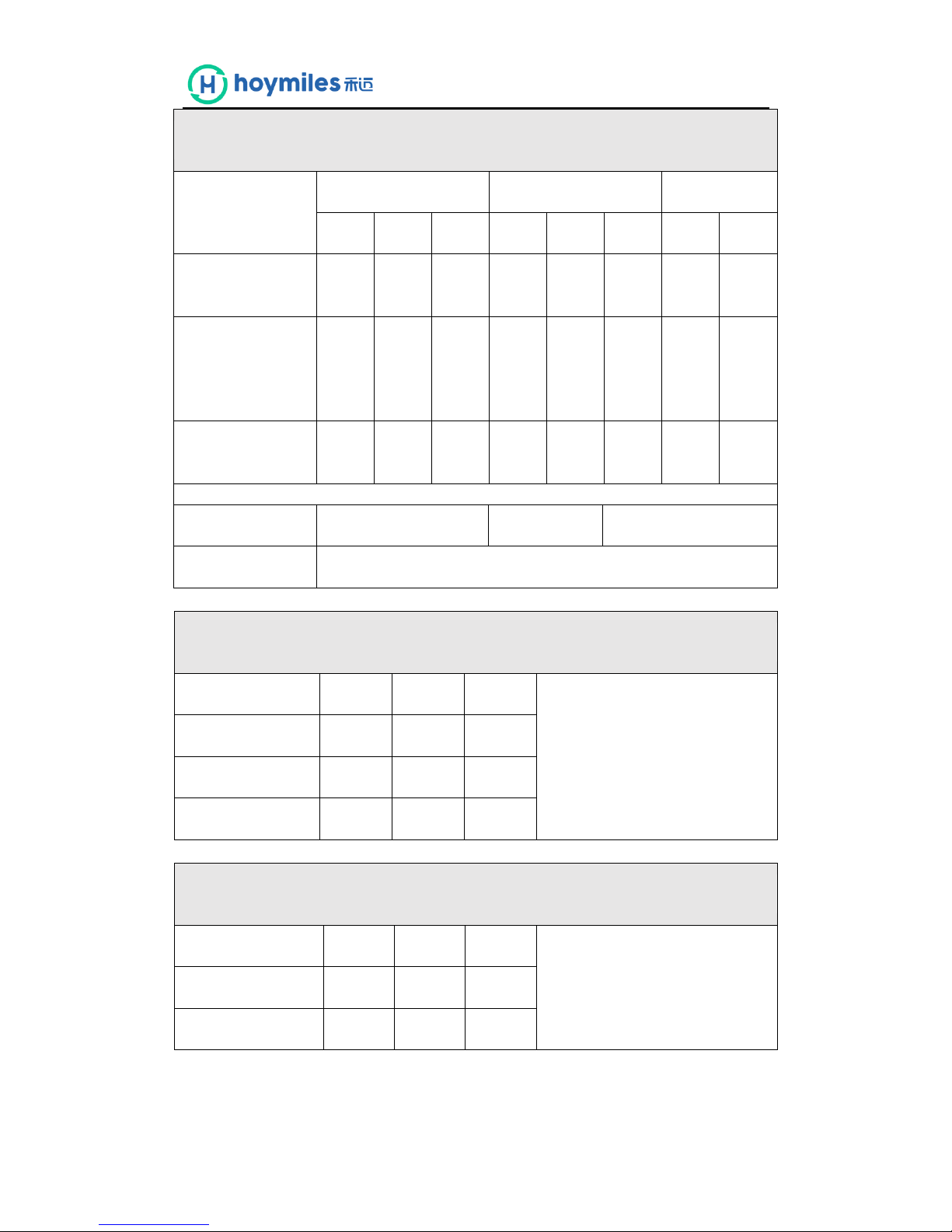
Power Quality. Harmonics. The requirement is specified in section 5.4.1, test procedure in
Annex A or B 1.4.1
SSEG rating per phase (rpp)
600
W
NV=MV*3.68/rpp
Harmo
nic
At 45-55% of rated output
100% of rated output
Measured
Value(MV)
in Amps
Normalised
Value (NV)
In Amps
Measured
Value(MV)
In Amps
Normalised
Value (NV)
In Amps
Limit in
BS EN
61000-3-
2
in Amps
Higher
limit for
odd
harmonic
s 21 and
above
2
0.075
0.461
0.150
0.854
1.080
3
0.022
0.137
0.054
0.222
2.300
4
0.012
0.072
0.029
0.070
0.430
5
0.008
0.049
0.021
0.039
1.140
6
0.007
0.045
0.017
0.039
0.300
7
0.007
0.040
0.014
0.026
0.770
8
0.006
0.034
0.012
0.021
0.230
9
0.004
0.026
0.011
0.013
0.400
10
0.004
0.023
0.009
0.021
0.184
11
0.004
0.022
0.009
0.018
0.450
12
0.004
0.021
0.008
0.015
0.153
13
0.004
0.023
0.007
0.018
0.210
14
0.003
0.016
0.008
0.013
0.131
15
0.002
0.012
0.010
0.024
0.150
16
0.002
0.012
0.006
0.008
0.115
17
0.002
0.012
0.009
0.013
0.132
18
0.002
0.014
0.011
0.015
0.102
19
0.001
0.007
0.003
0.018
0.118
20
0.001
0.004
0.004
0.013
0.092
21
0.002
0.010
0.005
0.001
0.107
Page 39
3
22
0.002
0.010
0.003
0.018
0.084
23
0.003
0.020
0.003
0.007
0.098
0.147
24
0.003
0.019
0.002
0.007
0.077
25
0.002
0.012
0.006
0.008
0.090
0.135
26
0.002
0.012
0.003
0.001
0.071
27
0.002
0.013
0.003
0.018
0.083
0.124
28
0.002
0.011
0.003
0.018
0.066
29
0.002
0.015
0.003
0.014
0.078
0.117
30
0.001
0.008
0.003
0.015
0.061
31
0.002
0.015
0.004
0.012
0.073
0.109
32
0.001
0.006
0.004
0.001
0.058
33
0.001
0.009
0.003
0.021
0.068
0.102
34
0.001
0.004
0.003
0.007
0.054
35
0.003
0.016
0.003
0.014
0.064
0.096
36
0.003
0.019
0.000
0.015
0.051
37
0.002
0.011
0.003
0.005
0.061
0.091
38
0.000
0.002
0.003
0.010
0.048
39
0.001
0.006
0.003
0.005
0.058
0.087
40
0.001
0.006
0.001
0.018
0.046
Note the higher limits for odd harmonics 21 and above are only allowable under certain
conditions, if these higher limits are utilised please state the exemption used as detailed in
part 6.2.3.4 of BS EN 61000-3-2 in the box below.
Page 40
4
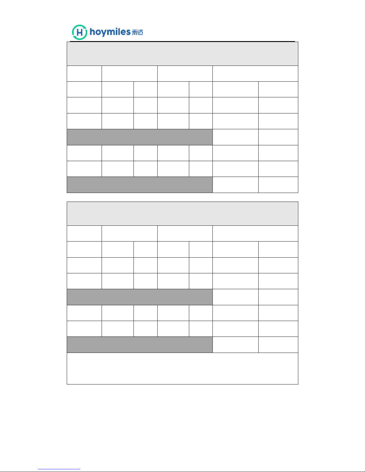
Power Quality. Voltage fluctuations and Flicker. The requirement is specified in section
5.4.2, test procedure in Annex A or B 1.4.3
Starting
Stopping
Running
dmax
[%]
dc [%]
d(t)
[%]
dmax
[%]
dc [%]
d(t)
[%]
Pst
Plt 2
hours
Measured Values
0.36
0.3 0 0.36
0.3 0 0.133
0.058
Normalised to
standard
impedance
and 3.68kW for
multiple units
2.21
1.84
0
2.21
1.84
0
0.82
0.36
Limits set under
BS EN 61000-3-2
4%
3.30%
3.3%
500ms
4%
3.30%
3.3%
500ms
1
0.65
Test start date
2017-06-14
Test end date
2017-06-14
Test location
No.8 Chunxin East Road, Wuxi, Jiangsu
Power quality. DC injection. The requirement is specified in section 5.5, test procedure in
Annex A or B 1.4.4
Test power level
10%
55%
100%
Recorded value(mA)
1.1404
3.6546
3.1117
as % of rated AC
0.05%
0.16%
0.14%
Limit
0.25%
0.25%
0.25%
Power Quality. Power factor. The requirement is specified in section 5.6, test procedure in
Annex A or B 1.4.2
216.2V
230V
253V
Measured at three voltage levels
and at full output. Voltage to be
maintained within ±1.5% of the
stated level during the test.
Measured value
0.9962
0.9959
0.9951
Limit
>0.95
>0.95
>0.95
Page 41
5
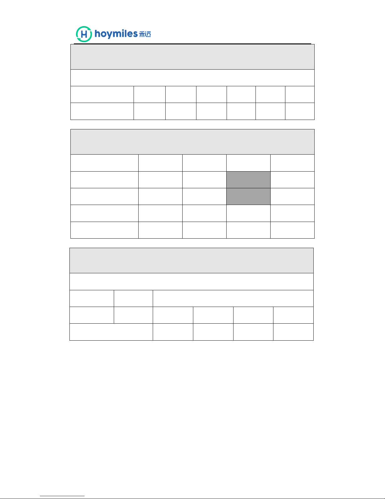
Protection. Frequency tests The requirement is specified in section 5.3.1, test procedure
in Annex A or B 1.3.3
Function
Setting
Trip test
“No trip tests”
Frequency
Time
delay
Frequency
Time
delay
Frequency /time
Confirm
no trip
U/F stage 1
47.5Hz
20s
47.5Hz
20.22
47.7Hz/ 25s
No trip
U/F stage 2
47Hz
0.5s
47.0Hz
0.543
47.2Hz/ 19.98s
No trip
46.8Hz/ 0.48s
No trip
O/F stage 1
51.5Hz
90s
51.5Hz
90.2
51.3Hz/95s
No trip
O/F stage 2
52Hz
0.5s
52.0Hz
0.528
51.8Hz/ 89.98s
No trip
52.2Hz/ 0.48s
No trip
Protection. Voltage tests The requirement is specified in section 5.3.1, test procedure in
Annex A or B 1.3.2
Function
Setting
Trip test
“No trip tests”
Voltage
Time
delay
Voltage
Time
delay
Voltage /time
Confirm
no trip
U/V stage 1
200.1V
2.5s
198.1V
2.54
204.1V/3.5s
No trip
U/V stage 2
184V
0.5s
182V
0.526
188V/2.48s
No trip
180V/0.48s
No trip
O/V stage 1
262.2V
1.0s
264.2V
1.027
258.2V/2.0s
No trip
O/V stage 2
273.7V
0.5s
275.7V
0.528
269.7V/0.98s
No trip
277.7V/0.48s
No trip
Note for Voltage tests the Voltage required to trip is the setting ±3.45V. The time delay can
be measured at a larger deviation than the minimum required to operate the protection. The
No trip tests need to be carried out at the setting ±4V and for the relevant times as shown in
the table above to ensure that the protection will not trip in error.
Page 42
6
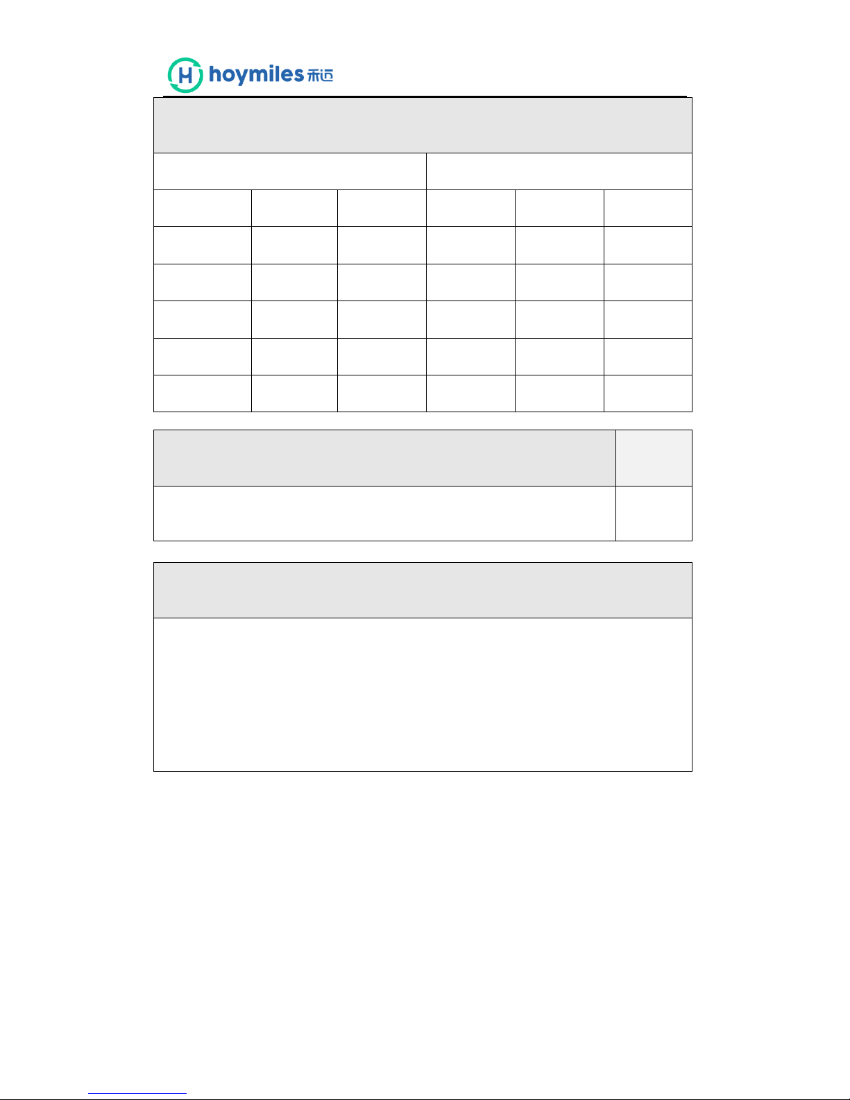
Protection. Loss of Mains test. The requirement is specified in section 5.3.2, test
procedure in Annex A or B 1.3.4
Note: Inverter tested according to BS EN 62116.
Test Power and
imbalance
33%
-5% Q
66%
-5% Q
100%
-5% P
33%
+5% Q
66%
+5% Q
100%
+5% P
Trip time. Limit is 0.5s
18.80ms
416.1ms
418.8ms
20.27ms
412.3ms
422.9ms
Protection. Frequency change, Stability test The requirement is specified in section
5.3.3, test procedure in Annex A or B 1.3.6
Start
Frequency
Change
End
Frequency
Confirm no trip
Positive Vector Shift
49.5Hz
+9 degrees
No trip
Negative Vector Shift
50.5Hz
- 9 degrees
No trip
Positive Frequency drift
49.5Hz
+0.19Hz/sec
51.5Hz
No trip
Negative Frequency
drift
50.5Hz
-0.19Hz/sec
47.5Hz
No trip
Protection. Re-connection timer. The requirement is specified in section 5.3.4, test
procedure in Annex A or B 1.3.5
Test should prove that the reconnection sequence starts after a minimum delay of 20
seconds for restoration of voltage and frequency to within the stage 1 settings of table 1.
Time delay
setting
Measured
delay
No reconnection when voltage or frequency is brought to
just outside stage 1 limits of table 1.
40s
40.3s
At 266.2V
At 196.1V
At 47.4Hz
At 51.6Hz
Confirmation that the SSEG
does not re-connect.
No
reconnection
No
reconnection
No
reconnection
No
reconnection
Page 43
7
Fault level contribution. The requirement is specified in section 5.7, test procedure in
Annex A or B 1.4.6
For a directly coupled SSEG
For a Inverter SSEG
Parameter
Symbol
Value
Time after
fault
Volts
Amps
Peak Short
Circuit current
ip
N/A
20ms
19.61V
0.171A
Initial Value of
aperiodic
A
N/A
100ms
10.50V
0.143A
Initial
symmetrical
Ik
N/A
250ms
8.56V
0.130A
Decaying
(aperiodic)
iDC
N/A
500ms
6.92V
0.108A
Reactance/Re
sistance Ratio
X/R
N/A
Time to trip
0.0024
(in seconds)
Self-Monitoring solid state switching The requirement is specified in section
5.3.1, No specified test requirements.
Yes/or NA
It has been verified that in the event of the solid state switching device failing to
disconnect the SSEG, the voltage on the output side of the switching device is
reduced to a value below 50 volts within 0.5 seconds.
N/A
Additional comments
Page 44

ORIGINAL LIMITED WARRANTY FOR PV MODULES
Peimar Srl (“PEIMAR”) hereby grants the following Limited Warranty to the customer (the "Buyer") any of
the specified (and no other) brand models listed below (the “Products”):
1) WARRANTED PRODUCTS
This Limited Warranty shall only apply to the following Products:
a) Polycrystalline Solar Panels
All the models manufactured by PEIMAR. also including OEM (co-branding)
b) Monocrystalline Solar Panels
All the models manufactured by PEIMAR. also including OEM (co-branding)
2) WARRANTY
a) 20 Year Limited Product Warranty
Peimar warrants that for a period of 20 years commencing on the Warranty Start Date (as
defined below) the Product(s) will be free from defects in design, material, workmanship or
manufacture that materially impede their functioning, and will conform to the specifications
and the drawings applicable thereto.
Any deterioration in appearance of the Product (including any scratches, stains, mechanical
wear, rust, or mold), or any other changes to the Product which occur after delivery (Incoterms
2010) to the Buyer, do not constitute a defect under this Limited Warranty unless it materially
impairs the Product’s power output as warranted pursuant to Sec. 2 b). A claim in the event of
glass breakage arises only to the extent that there was no external cause of the breakage.
b) 30 Year Limited Power Output Warranty
In addition, Peimar warrants that for a period of thirty years commencing on the Warranty
Start Date, the loss of power output relating to the initial guaranteed power which is defined
as Peak Power Watts Pmax(Wp) plus Peak Power Watts Pmax(Wp) multiplied by the lower
limit of the Power Output Tolerance Pmax(%)–as specified in the relevant Product Data Sheet
and measured at Standard Test Conditions (STC), net of the measurement tolerances applied
in the laboratory where the tests are run- for the Product(s) shall not exceed
- For Poly-crystalline Products (as defined in Sec. 1 a): 2% in the first year, thereafter 0.6% per
year, ending with 80.6% in the 30th year after the Warranty Start Date,
- For Mono-crystalline Products (as defined in Sec. 1 b): 3% in the first year, thereafter 0.59%
per year, ending with 79.90% in the 30th year after the Warranty Start Date.
3) WARRANTY START DATE
The Warranty Start Date is the date of delivery (Incoterms 2010) of the Product(s) to the Buyer.
Page 45

4) EXCLUSIONS AND LIMITATIONS
The aforementioned “Limited Warranty” does not apply to any Products which have been subjected to
a) Failure to pay the purchase price towards Peimar or its subsidiaries which have put the modules on
the market provided that (i), the payment was due and (ii) the Buyer who has obtained the
modules from Peimar or one of its distributors (Direct Customer) is not entitled to withhold the
purchase price or parts of the purchase price. Peimar must inform the Buyer about the nonpayment and provide the name and the full address of the Direct Customer which has failed to pay
the modules. In case that Peimar can reject the claim under this warranty based on this provision,
the Buyer can deposit the amount not paid in order to trigger the warranty claims;
b) Failure to comply with Peimar’s installation manual applicable during the Validity of this Limited
Warranty pursuant to Sec 10;
c) Service by service technicians who are not qualified under the relevant law and/or applicable
regulations at the place of installation;
d) The Product's type, nameplate or module serial number is changed, erased or made illegible (other
than by any act or omission of Peimar);
e) The Product’s installation on mobile units (except photovoltaic tracking system), such as vehicles,
ships or offshore-structures;
f) Exposure to voltage in excess to the maximum system voltage or power surges;
g) Defective components in the construction on which the module is mounted;
h) exposure to mold discoloration or similar external effects;
i) exposure to any of the following: extreme thermal or environmental conditions or rapid changes in
such conditions, corrosion, oxidation, unauthorized modifications or connections, unauthorized
opening, servicing by use of unauthorized spare parts, accident, force of nature (such as lightning
strike, earthquake), influence from chemical products or other acts beyond Peimar’s reasonable
control (including damage by fire, flood, etc.);
5) REPAIR, REPLACEMENT OR REFUND REMEDY
a) As Buyer’s sole and exclusive remedy under this Limited Warranty Peimar will, at its sole
discretion, either, with regard to the applicable:
i. refund the purchase price of the relevant Product(s) annually reduced by a linear
depreciation, taking into account an anticipated life time of 30 years; or
ii. repair the defective Product(s) at no charge (subject to the following paragraph); or
iii. replace the defective Product(s) or part thereof by a new or remanufactured equivalent
at no charge (subject to the following paragraph).
In the event that Peimar opts for options ii) or iii), Peimar shall bear all insurance and
transportation charges (except air freight), customs clearance and any other costs for shipping the
repaired or replaced Product(s) to Buyer. The costs and expenses for the removal, installation,
return of the defective Product(s) to Peimar or reinstallation shall remain with Buyer.
a) The warranty period(s) as defined in Sec. 2 a) and b) shall not extend or renew upon the repair or
replacement of a defective Product by Peimar. The warranty period for replaced or repaired
Product(s) is the remainder of the warranty on the original new Product(s).
b) All other claims under this Limited Warranty against Peimar shall be excluded. Under this Limited
Warranty, Peimar is not responsible for any special, incidental or consequential damages (including
loss of profits, harm to goodwill or business reputation, or delay damages) whether such claims are
based in contract, warranty, negligence or strict tort. This exclusion applies to the extent
Page 46

permissible by law, and even if the remedies set forth below herein are deemed to have failed of
their essential purpose.
6) RIGHTS AND REMEDIES AGAINST THIRD PARTIES
This Limited Warranty shall be construed as a separate warranty and independent from any other
contractual arrangement with third parties relating to the Product(s). It shall not affect any rights,
obligations and remedies of the Buyer, if any, with regard to third parties for defects or non-conformity or
non-compliance of the Products, notwithstanding its legal basis. The rights and remedies provided
hereunder are in addition to any other rights and remedies against third parties to which Buyer may be
entitled by agreements with such third parties or by law.
7) CLAIMS PROCEDURE, NOTICE PERIODS, EXPIRATION OF WARRANTY CLAIMS AND LIMITATIONS.
a) Buyer shall notify Peimar under this Limited Warranty using Peimar’s Customer Service Portal at
the web address http://www.peimar.com/en/contact/; alternatively by letter or fax to:
Europe and other locations
Customer Support
Peimar Srl
Via Creta 72
25124 Brescia - Italy
T +39 030223292
F +39 0307772102
[email protected]
North, Central and South America
Customer Support
Peimar Inc
309 Fellowship Rd,
East Gate Center, Suite 115
Mt Laurel, NJ 08054
T +1 8566424035
[email protected]
specifying each alleged claim including evidence of the claims and the serial numbers of the
Product(s) at issue.
b) Any dispute on technical facts relating to claims brought under this Limited Warranty for defects
of Products shall be determined by expert determination. Peimar and the Buyer will, at the
Buyer’s cost, appoint as independent expert and appraiser a researcher from TÜV or from
another accredited organization (“Technical Expert”). The determination by such Technical
Expert shall be final, conclusive, binding and enforceable in any proceeding brought hereunder.
The Technical Expert shall (i) act as an expert; (ii) allow the parties a reasonable opportunity to
make representations and counter-representations; (iii) take those representations and counterrepresentations into account; and (iv) if required by either party give written reasons for his or
her determination.
c) Any claim for breach of this Limited Warranty must be brought within two (2) months after
discovery of the breach.
d) The return of any defective Product(s) will not be accepted unless prior written authorization
has been given by Peimar .
Page 47

8) FORCE MAJEURE
Peimar shall not be responsible or liable in any way to the Buyer for any non-performance or delay in
performance under this Limited Warranty due to occurrences of force majeure such as, war, riots, strikes,
unavailability of suitable and sufficient labor, material, or capacity or technical or yield failures and any
unforeseen event beyond its control, including, without limitation, any technological or physical event or
condition which is not reasonably known or understood at the time of the sale of the defective Product(s)
or the notification of the relevant warranty claim under this Limited Warranty.
9) WARRANTY ASSIGNMENT
This Limited Warranty is transferrable when the Products remain installed in their original installation
location.
10) VALIDITY
This Limited Warranty shall apply to Product(s) delivered to Buyer from 1st of January 2018 (Incoterms
2010).
This Limited Warranty shall be valid until a new revision is issued by Peimar.
11) NO OTHER EXPRESS WARRANTY
Except as otherwise provided by applicable statutory law (cf. Sec. 5 d) and 5 e) above) or unless modified in
writing and signed by an officer of Peimar, the Limited Warranty set forth herein is the only express
warranty (whether written or oral) by Peimar applicable to the Products and no one is authorized to
restrict, expand or otherwise modify this Limited Warranty.
12) MISCELLANEOUS
If any provision of this Limited Warranty is held invalid, unenforceable or contrary to law then the validity
of the remaining provisions of this Limited Warranty shall remain in full force and effect.
13) APPLICABLE LAW AND JURISDICTION
The validity of this Limited Warranty, the construction of its terms and the interpretation and enforcement
of the rights and duties of the Buyer and Peimar shall be governed by the Italian laws and the authorized
court will be exclusively the BRESCIA (Italy) one.
Page 48
Page 49

Page 50

Page 51

EN-XXX_Warranty-TRIC_IN-120201-1WA20283
Wagner & Co · Zimmermannstraße 12 · D-35091 Cölbe ·
%
(06421) 80 07-0 · Fax 80 07-22 · www.wagner-solar.com
INFORMATION
Functional Warranty TRIC Racking Systems
Material and Workmanship
Wagner & Co guarantees functionality and durability of
the TRIC racking system components as well as that they
are free of material and production faults, provided they
were installed, used and maintained according to the prescribed conditions and instructions.
Wagner & Co grants this warranty for a period of ten years
after the date of sale to a retailer or installer.
Entitlements
The value of potential warranty entitlements is limited to
the net purchase price of the products.
In a warranty case Wagner & Co will decide on either replacing or repairing the faulty product or reimbursing the
purchase price.
There are no additional liabilities or warranty entitlements.
In particular Wagner & Co is not liable for:
● Costs of new installations and extensions,
● Appraisal and testing costs,
● Packaging and shipping costs as well as
● Foregone profits
All liability is excluded for damage caused by severe
weather or force majeur.
Limitations and Conditions
Pot enti al w arrant y en titl eme nts are l imit ed t o the p rescribed period of this guarantee. In order to secure potential warranty entitlements the following conditions apply:
● The mounting racks were thoroughly installed observ-
ing the installation manuals, layout plans and structural
calculations.
● For the design and installation of the system the codes,
regulations and technical standards applicable at the
time of the installation have been observed.
● No damages occurred during transportation, storage
and operation.
Any warranty entitlements granted will not extend the
overall guarantee period of 10 years. Replaced parts or
products will become property of Wagner & Co.
Warranty Claim
For any potential warranty claim you immediately have
to contact the retailer or installer where you obtained the
racking systems. The retailer/installer will explain the required further steps.
You have to make your warranty claim in writing and send
it in together with a proof of purchase and a description
of the fault.
Otherwise our current general business conditions apply.
Cölbe, Germany, February 2012
 Loading...