

Page 1
www.pluggit.com
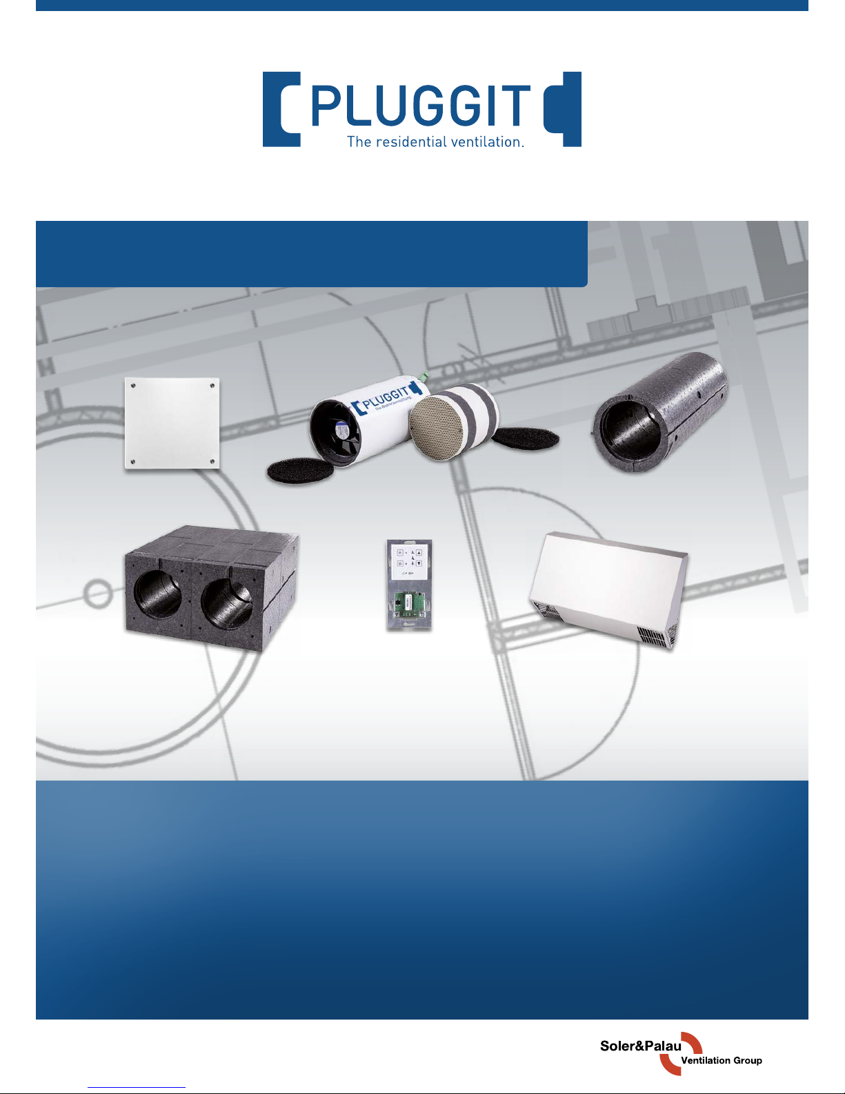
Operating and installation instructions
Pluggit iconVent
Decentralized residential ventilation with heat recovery
Page 2

The technology makes the difference.
Innovations of Pluggit with an added value for the human being and environment.
The 2Q-ventilation typical for PLUGGIT room systems guarantees efficiency and
comfort for the distribution of supply air. The first Q - the displacement ventilation distributes the fresh air very slowly without any background noises and draughts in
the room. The second Q - the cross ventilation - causes a complete air flow of the
room. In this, the fresh air outlet in the outside wall area is positioned as far away as
possible from the door of the supply air room.
The special PLUGGIT iQoanda-air outlet is positioned above the access of the supply
air room, if possible. The Qoanda effect leads the air flow along the ceiling in the
furthest corner of the room. By means of this type of flow a comprehensive air quality
is ensured without any background noises and draughts.
The distribution systems of PLUGGIT allow an installation of pipe systems at all three
installation levels. For new buildings or renovation the ventilation ducts can be
assembled safely and easily: in the insulating layer of the floor, in the bare concrete
of the ceiling or below the ceiling.
The innovative and unique PLUGGIT ServoFlow-technology guarantees the supply of
utilization-oriented air volume for a building at any time. Above all, it ensures the
important balance of supply and exhaust air flows by means of an automatically
conducted calibration once a week and documents modifications, like the filter
contamination in the plant.
The energy efficiency of ventilation units is defined by two factors. The high heat
recovery of our ventilation units ensures low heat losses and comfortable supply air
temperatures. Decisive, however, is the power consumption. By means of highly
efficient direct current vans the operating costs are reduced to a minimum. Thus, the
ratio of heat recovery and power consumption, which means the efficiency, is the
most significant value and is defined as coefficient of performance. At the coefficients
of performance PLUGGIT ventilation units achieve maximum values of up to 26 and
thus guarantee an excellent energy efficiency.
CleanSafe stands for an easy cleaning. As a first company PLUGGIT had a cleaning
system certified which facilitates cost-effective cleaning and maintenance of all
system components, whether a round tube or a shallow duct distribution system is
installed.
Fresh air and heat supply in one system - faster, more flexible and more energysaving than common heating systems.
Perfect feel-good climate by means of optimal air humidity in the room air with the
air humidifier AeroFresh.
2Q
allfloor
ServoFlow
CleanSafe
Page 3

1
BIA Single room ventilation unit iconVent Mono and iconVent Duo
1. General safety instructions ................................................................................................. 3
2. General notes ...................................................................................................................... 3
2.1. Appropriate use ................................................................................................................... 3
2.2. Non-appropriate use ........................................................................................................... 3
2.3. Warranty .............................................................................................................................. 3
3. Overview ............................................................................................................................. 4
3.1. Single-room ventilation unit iconVent Mono ...................................................................... 4
3.2. Single-room ventilation unit iconVent Duo ......................................................................... 5
4. Function/principle ............................................................................................................... 6
4.1. Single-room ventilation unit iconVent Duo ......................................................................... 6
4.2. Single-room ventilation unit iconVent Mono ...................................................................... 7
4.3. Cross ventilation .................................................................................................................. 8
4.4. Installation type single-room ventilation unit iconVent Duo .............................................. 9
4.5. Installation type single-room ventilation unit iconVent Mono and iconVent Duo ............ 10
4.6. Installation type single-room ventilation unit iconVent Duo and exhaust air van ........... 11
4.7. Installation type single-room ventilation unit iconVent Mono, iconVent Duo
and exhaust air van ........................................................................................................... 12
4.8. Regulation .......................................................................................................................... 13
4.8.1. Regulation schemes ................................................................................................ 14
4.9. Time-delay relay ................................................................................................................ 21
4.9.1. Connection diagram ................................................................................................ 21
4.9.2. Technical data .......................................................................................................... 21
4.9.3. Measurements ......................................................................................................... 21
5. Installation (qualified staff) ................................................................................................ 22
5.1. Notes for installation
......................................................................................................... 22
5.2. Assemble installation stone ICVS and installation sleeve ICVH
....................................... 23
5.2.1. Installation stone ICVS for single-room ventilation unit iconVent Mono ............... 23
5.2.2. Installation stone ICVS for single-room ventilation unit iconVent Duo .................. 23
5.2.3. Installation sleeve ICVH for single-room ventilation unit iconVent Mono ............. 24
5.2.4. Installation sleeve ICVH for single-room ventilation unit iconVent Duo ................ 24
5.3. Install single-room ventilation unit
.................................................................................. 25
5.4. Initial operation
................................................................................................................. 27
TABLE OF CONTENTS
Page 4

2
BIA Single room ventilation unit iconVent Mono and iconVent Duo
5.5. Technical data .................................................................................................................... 28
5.5.1. Unit data ................................................................................................................... 28
5.5.2. Regulation ................................................................................................................ 28
5.5.3. Measurements ......................................................................................................... 28
5.5.4. Basic wiring diagram, electrical .............................................................................. 30
6. Operation (user) ................................................................................................................ 31
6.1. Overview regulation ........................................................................................................... 31
6.2. Increase/ reduce fan level ................................................................................................. 31
6.3. Reset filter alarm ............................................................................................................... 31
6.4. Error correction ................................................................................................................. 32
6.4.1. Disturbances ............................................................................................................ 32
7. Maintenance (user) ............................................................................................................ 33
7.1. Clean inside panel ............................................................................................................. 33
7.2. Clean ceramic heat exchanger .......................................................................................... 33
7.3. Clean/ change filter ........................................................................................................... 34
8. Decommissioning/disposal ................................................................................................ 35
8.1. Decommissioning at extension ......................................................................................... 35
8.2. Packaging ........................................................................................................................... 35
8.3. Old unit ............................................................................................................................... 35
Page 5

3
BIA Single room ventilation unit iconVent Mono and iconVent Duo
2.1. APPROPRIATE USE
The decentralized single-room ventilation unit iconVent
Mono and iconVent Duo serve as regulated aeration and
ventilation of individual supply air rooms, for example, living
rooms and children's rooms as well as exhaust air rooms,
for example, kitchen and bathroom with window in accordance with DIBt-approval.
2.2. NON-APPROPRIATE USE
Other uses of the decentralized single-room ventilation unit
than those described under "appropriate use" are inadmissible.
The decentralized single-room ventilation unit shall not be
applied
for construction drying.
2.3. WARRANTY
For a full legal warranty claim the technical standards of
these operating and installation instructions shall be observed.
1. GENERAL SAFETY INSTRUCTIONS
Warning:
The following safety instructions shall be noted, otherwise injuries or damages can be implied:
z Before you begin with the installation and operation
of the decentralized single-room ventilation unit,
carefully read these operation and installation instructions.
z The installation and all electrical works shall only
be carried out by qualified staff.
z Consider all necessary legal and national standards
(accident prevention regulations and acknowledged rules of technology) for the installation and
initial operation of t
he decentralized single-room
ventilation unit and observe them.
z Damages which occur due to product-inappropriate
storage, improper operation and installation or
non-appropriate use are excluded from each kind
of liability.
z Subject to technical changes.
2. GENERAL NOTES
Page 6
4
BIA Single room ventilation unit iconVent Mono and iconVent Duo
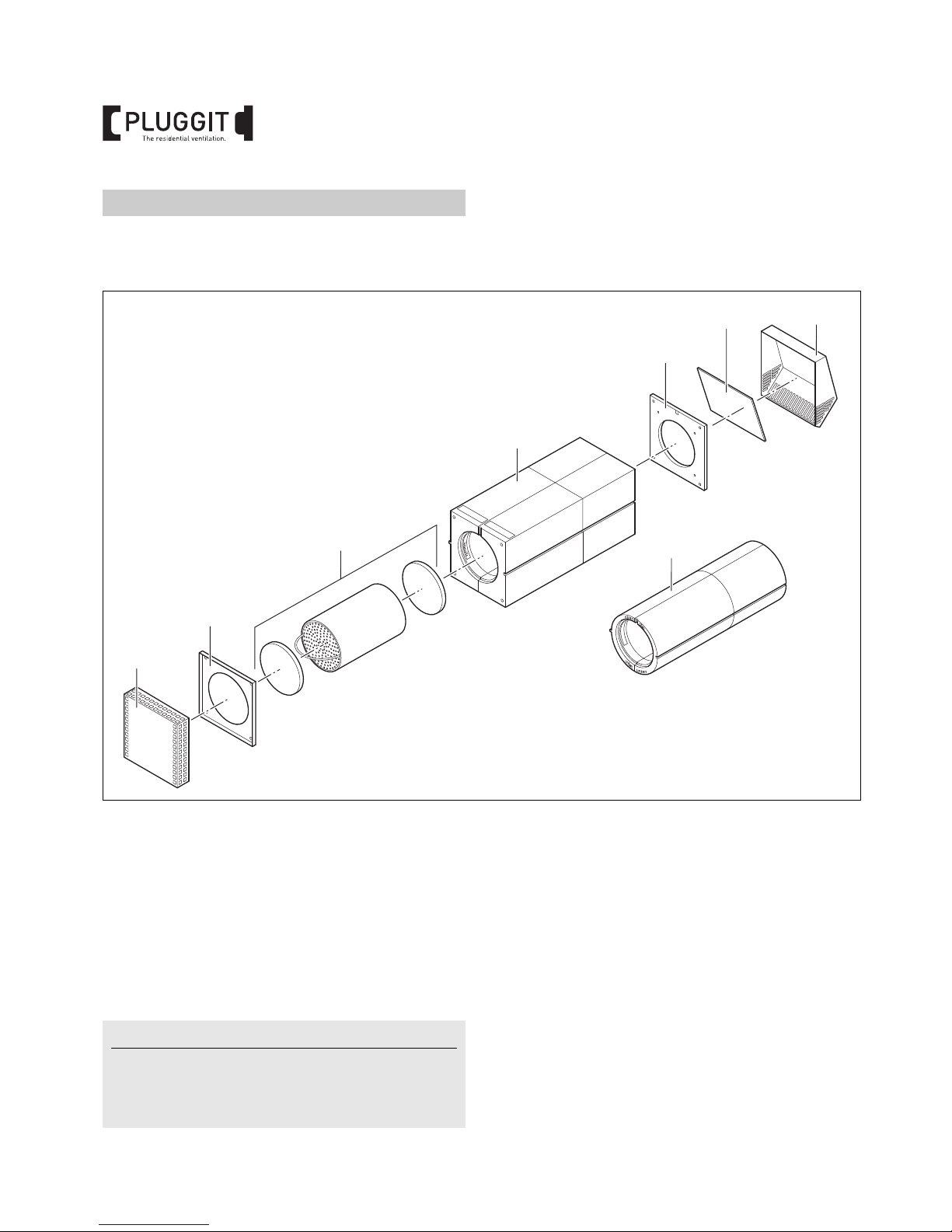
3.1. SINGLE-ROOM VENTILATION UNIT
ICONVENT
MONO
1 Pluggit iconVent inside panel Mono ICVM-B
2 Base plate, inside
3 Plugg
it iconVent functional unit ICVF
4.1 Plugg
it iconVent installation stone ICVS
4.2 Plugg
it iconVent installation sleeve ICVH
5 Base plate, outsid
e
6 Ins
ulation mat
7 Plugg
it iconVent weather protection grid
Mono ICVM-WSG
3. OVERVIEW
unten
oben
oben
unten
1
2
5
6
7
4.1
4.2
3
M+P-26A-1204
Note:
Depending on the construction plan the Pluggit iconVent
installation sleeve ICVH (4.2) can also be used instead of
the Pluggit iconVent installation stone ICVS (4.1).
This is designed as round EPP sleeve 198
mm.
Page 7
5
BIA Single room ventilation unit iconVent Mono and iconVent Duo
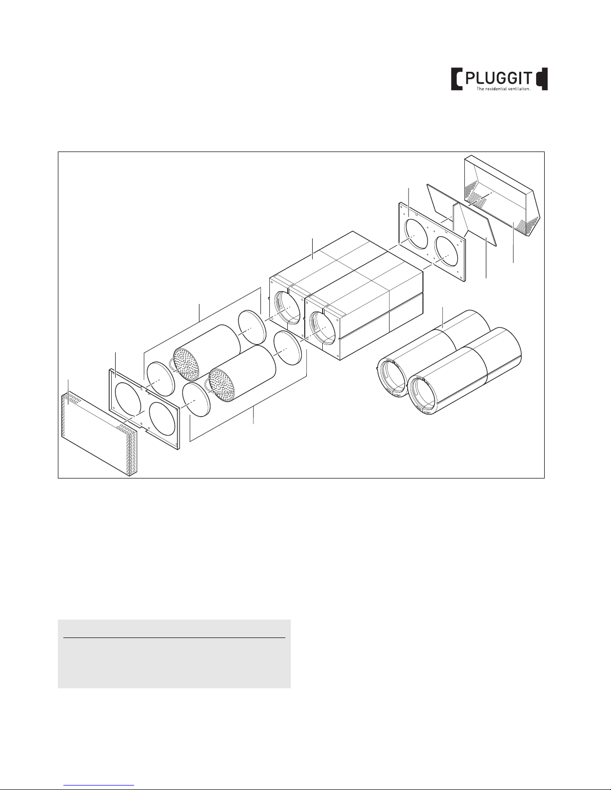
3.2. SINGLE-ROOM VENTILATION UNIT
ICONVENT DUO
1 Pluggit iconVent inside panel Duo ICVD-B
2 Base plate, insid
e
3 Pluggit iconVent
functional unit ICVF
4.1 Pluggit
iconVent installation stone ICVS
4.2 Pluggit
iconVent installation sleeve ICVH
5 Base plate, outside
6 Ins
ulation mat
7 Pluggit iconVent
weather protection grid
Duo ICVD-WSG
unten
oben
oben
unten
unten
oben
oben
unten
1
2
5
6
7
4.1
4.2
3
3
M+P-26A-1205
Note:
Depending on the construction plan the Pluggit iconVent
installation sleeve ICVH (4.2) can also be used instead of
the Pluggit iconVent installation stone ICVS (4.1).
This is designed as round EPP sleeve 198
mm.
Page 8
6
BIA Single room ventilation unit iconVent Mono and iconVent Duo
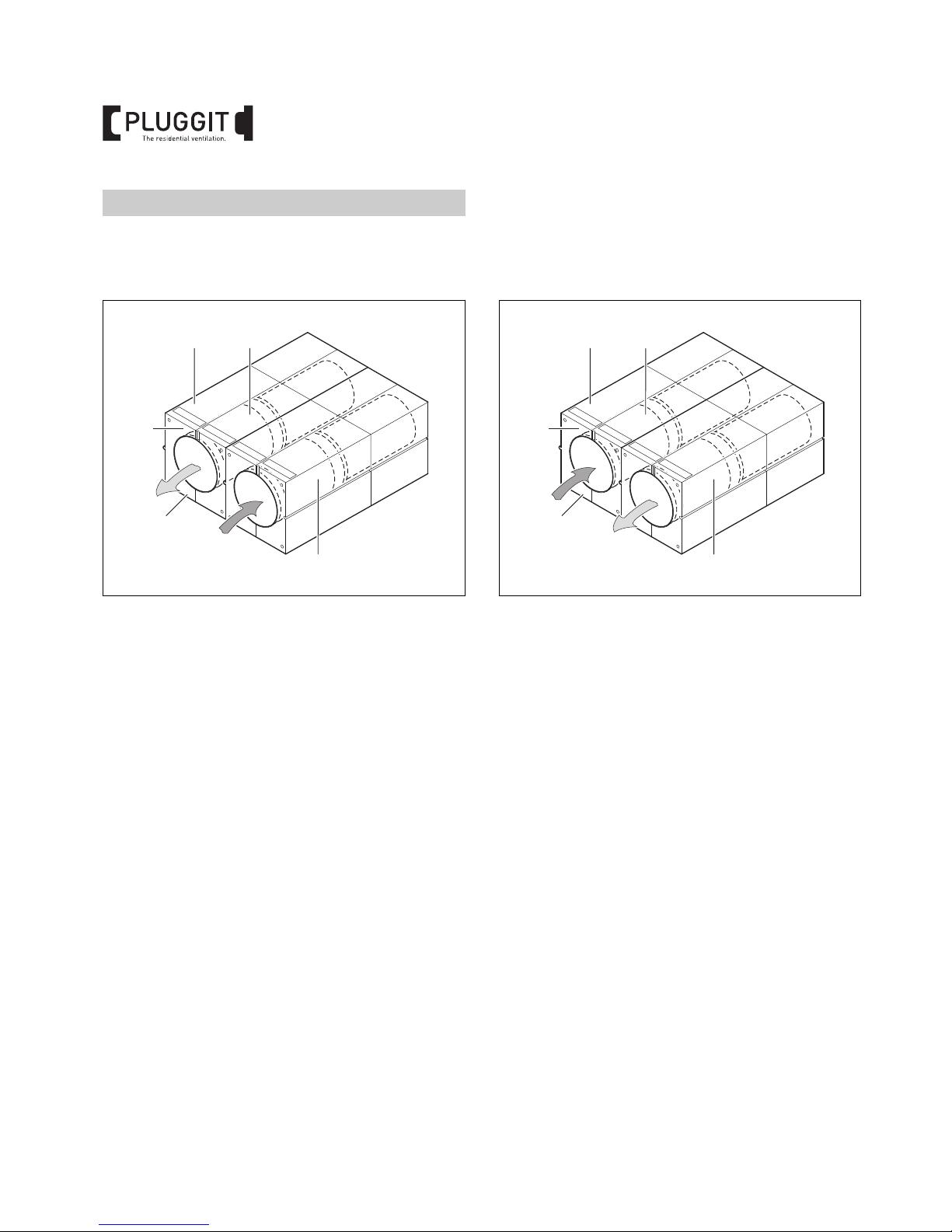
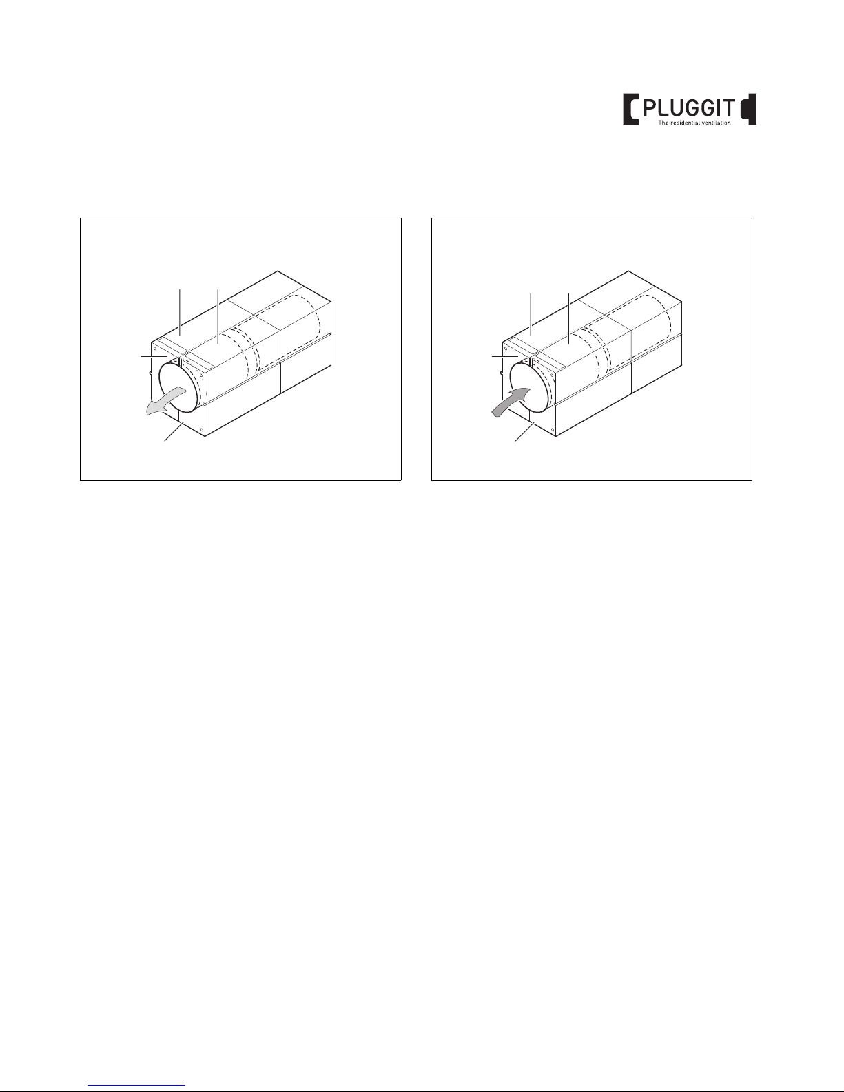
4.1. SINGLE-ROOM VENTILATION UNIT ICONVENT DUO
Rotation direction A
1 Single-roo
m ventilation unit iconVent Duo
2 Functional
unit supply air operation
3 Supp
ly air
4 Functional
unit exhaust air operation
5 Exhaust air
Rotation direction B
1 Single-roo
m ventilation unit iconVent Duo
2 Function
al unit supply air operation
3 Supply air
4 Function
al unit exhaust air operation
5 Exhaust air
For the hygienically necessary exchange of air outside air is
fed into the fun
ctional unit (2) of the single-room ventilation
unit (1) and transported in the living room as supply air (3).
Humid and used exhaust air (5) is discharged through the
functional unit (4) out of
the building.
Approximately each 80 seconds the rotation direction of the
fans in the functional units (2) and
(4) is changed. This way,
also the direction of supply air (3) and exhaust air (5) is
changed.
The ceramic heat exchanger of the functional unit (4) is
heated by
the inside room temperature. This heat is supplied at the change of rotation direction of the supply air (3).
Due to this operation a permanent heat recovery is
ac
hieved.
4. FUNCTION/PRINCIPLE
obenoben
obenoben
obenoben
obenoben
unten
oben
oben
unten
unten
oben
oben
unten
1
2
4
5
3
Outside wall
Inside wall
M+P-26A-1305
up
down
obenoben
obenoben
obenoben
obenoben
unten
oben
oben
unten
unten
oben
oben
unten
1
2
4
5
3
Outside wall
Inside wall
M+P-26A-1306
up
down
Page 9
7
BIA Single room ventilation unit iconVent Mono and iconVent Duo
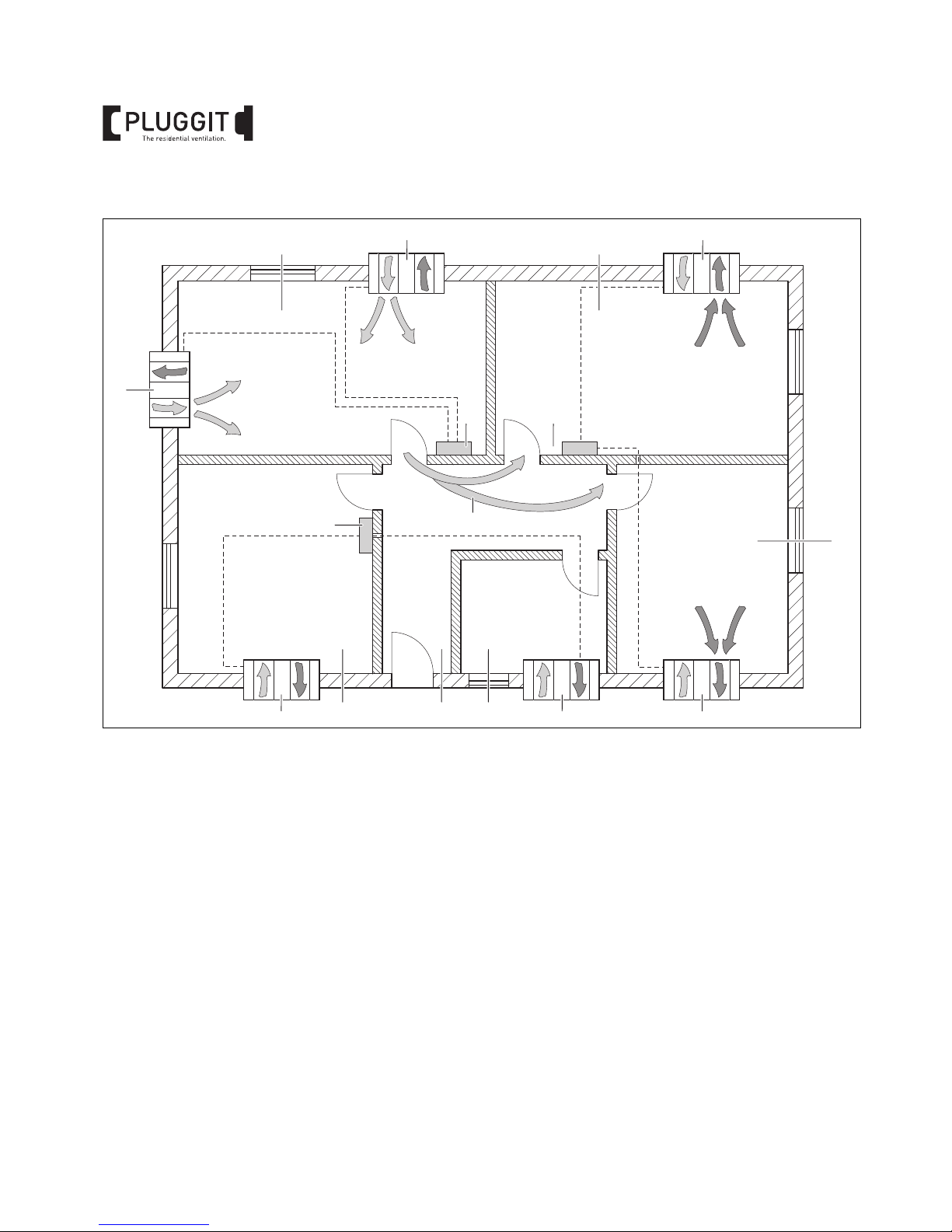
4.2. SINGLE-ROOM VENTILATION UNIT ICONVENT MONO
Rotation direction A
1 Single-room ventilation unit
iconVent Mono
2 Functional unit su
pply air operation
3 Supply air
Rotation direction B
1 Single-room ventilation unit
iconVent Mono
2 Functional unit exh
aust air operation
3 Exhaust air
The change of rotation direction of the fan in the singleroom ventilation unit icon
Vent Mono (1) is carried out correspondingly as in the single-room ventilation unit
iconVent Duo.
The single-room ventilation units iconVent Mono (1) shall be
operated in
pairs for a regulation. This means one unit runs
in supply air operation whereas the second unit simultaneously runs in exhaust air operation. The change of rotation
dire
ction is also conducted simultaneously in pairs.
Only this way the balance between supply and exhaust air
volume stream required
according to DIN 1946-6 and
DIBt-approval can be guaranteed.
obenoben
obenoben
unten
oben
oben
unten
1 2
3
Outside wall
Inside wall
M+P-26A-1307
up
down
obenoben
obenoben
unten
oben
oben
unten
1 2
3
Outside wall
Inside wall
M+P-26A-1308
up
down
Page 10
8
BIA Single room ventilation unit iconVent Mono and iconVent Duo
4.3. CROSS VENTILATION
Sample installation
1 Single-roo
m ventilation units
2 Regulation
3 Cross ventilation
4 Suppl
y air room, for example, living room and
dining room
5 Supp
ly air room, for example, bedroom
6 Suppl
y air room, for example, guest room
7 Suppl
y air room, for example, bathroom with window
8 Exhaust air room,
for example, kitchen with window
9 Overflow area, f
or example, corridor or hall
Thus the single-room ventilation units (1) can be controlled
b
y the regulation (2), so that a sufficient cross ventilation (3)
of the entire utilization unit is guaranteed.
For the realisation of cross ventilation (3)
the supply air
volume flows in this sample installation, for example, in the
living room and dining room (4), must be increased by +5 %.
In the opposite rooms, for example, in the bedroom (5) and
guest rooms (6), the exhaust air volume flows must by
higher by +5 %. Additionally suitable overflow openings, for
example, do
or undercuts are necessary.
In exhaust air rooms with windows, for example,
bathroom (7) and kitchen (8), no cross ventilation is necessary. Here the single-room ventilation units (1) must be operated in balance according to the DIBt-
approval. This
means they run independently with regard to air technology, independent from the settings of the supply air
rooms. In such a case either
two single-room ventilation
units iconVent Mono or one single-room ventilation unit
iconVent Duo must be installed.
In the overflow sector, for example, corridor or hall (9), an
own sin
gle-room ventilation unit can be renounced, be-
cause, as a rule, the cross ventilation
(3) is sufficient, in
order to achieve a sufficient air exchange in these rooms.
1
1
6
2
4 5
22
3
1 1
7
+5%+/-0% +/-0%
+5%
+5%
+5%
98
1
1
M+P-26A-1105
Page 11
9
BIA Single room ventilation unit iconVent Mono and iconVent Duo
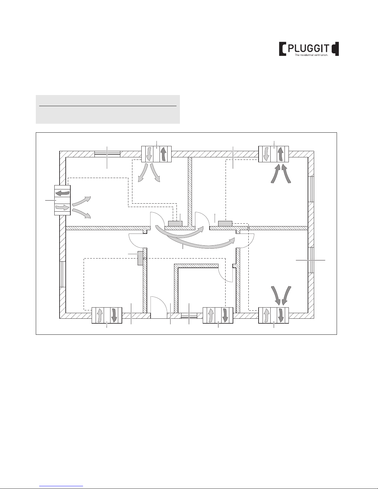
4.4. INSTALLATION TYPE SINGLE-ROOM
VENTILATION UNIT ICONVENT DUO
Sample installation
1 Single-room ventilation unit
iconVent Duo
2 Regulatio
n
3 Cross ventilation
4 Supply
air room, for example, living and dining room
5 Sup
ply air room, for example, bedroom
6 Supply
air room, for example, guest room or
children's room
7 Exhaust air
room, for example, bathroom with window
8 Exhaust air
room, for example, kitchen with window
9 Overflow are
a, for example, corridor or hall
Note:
The described installation type is valid for bathrooms
with integrated window.
1
1
6
2
4 5
22
3
1 1
7
+5%+/-0% +/-0%
+5%
+5%
+5%
98
1
1
M+P-26A-1105
Page 12
10
BIA Single room ventilation unit iconVent Mono and iconVent Duo
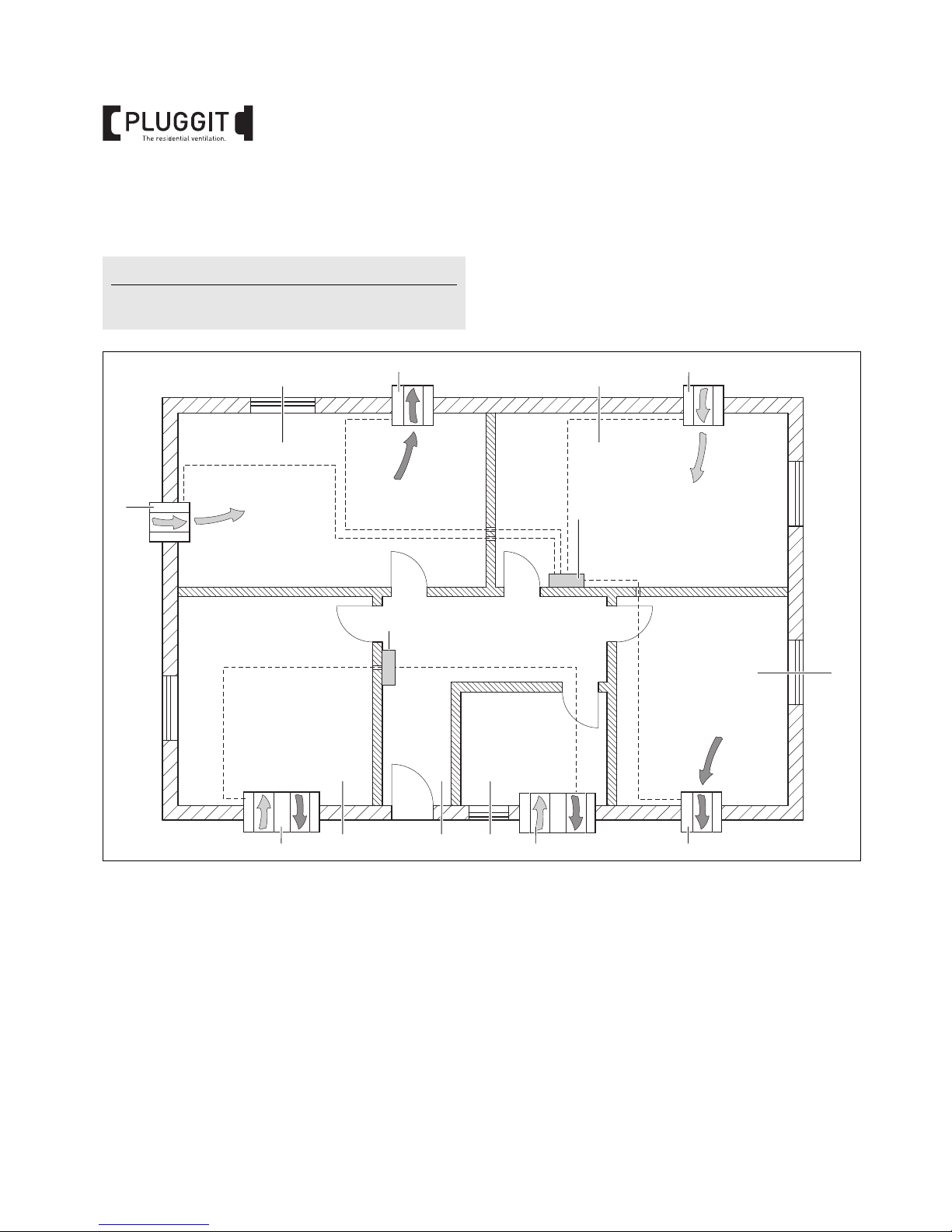
4.5. INSTALLATION TYPE SINGLE-ROOM
VENTILATION UNIT ICONVENT MONO AND
ICONVENT DUO
Sample installation
1 Single-roo
m ventilation unit iconVent Mono
2 Single-roo
m ventilation unit iconVent Duo
3 Regulation
4 Supp
ly air room, for example, living and dining room
5 Supp
ly air room, for example, bedroom
6 Suppl
y air room, for example guest room or
children's room
7 Exhaust air room,
for example, bathroom with window
8 Exhaust air room,
for example, kitchen with window
9 Overflow area, f
or example, corridor or hall
Note:
The described installation type is valid for bathrooms
with integrated window.
1
1
6
4 5
3
3
2 2
7
+/-0%
+/-0%
98
1
1
M+P-26A-1106
Page 13
11
BIA Single room ventilation unit iconVent Mono and iconVent Duo
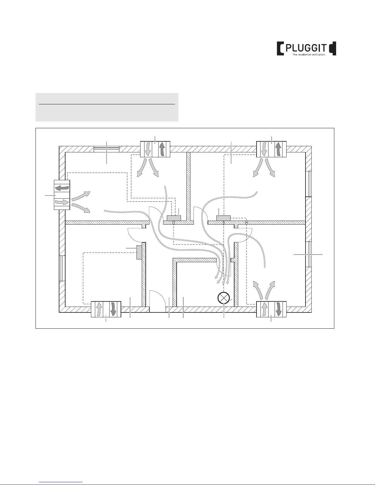
4.6. INSTALLATION TYPE SINGLE-ROOM VENTILATION
UNIT ICONVENT DUO AND EXHAUST AIR VAN
Sample installation
1 Single-room ventilation unit
iconVent Duo
2 Exhaust
air fan according to DIN 18017-3
3 Regulatio
n
4 Supply
air room, for example, living and dining room
5 Sup
ply air room, for example, bedroom
6 Supply
air room, for example, guest room or
children's room
7 Exh
aust air room, for example, bathroom without window
8 Exhaust air
room, for example, kitchen with window
9 Overflow are
a, for example, corridor or hall
In flats with an inside bathroom without
window (7) an ex-
haust air fan (2) must be installed acc
ording to DIN 18017-3.
This has to generate an exhaust air volume flow
of 60 m³/h (V
AB
).
To realize a balanced air exchange additional volume flows
must
be generated in the supply air rooms, which balance
the air volume flow of the exhaust air fan. Only this way it
can be ensured that there is no vacuum in the utilization unit
and the single-room ventilation units (1) which are in exhaust air operation can continue to generate heat recovery.
Example:
The exhaust air fan (2) is connected with
two regulations (3)
of supply air rooms, as it is described here. The supply air
volume flow of the single-room ventilation units (1) must be
adjusted respectively +15 m³/h higher in the supply air operation. By this, in total the 60 m³/h exhaust air volume flow
of
the exhaust air fan (2) is compensated.
The single-room ventilation unit (1) in the kitchen (8) continues to run in balance.
Note:
The described installation type is valid for inside bathrooms without window according to DIN 18017-3.
1
1
3
6
4 5
33
1
7 2
+/-0%
98
1
1
VAB = 60m /h
+15m /h
+15m /h+15m /h
+15m /h
3
3
33
3
M+P-26A-1107
Page 14
12
BIA Single room ventilation unit iconVent Mono and iconVent Duo
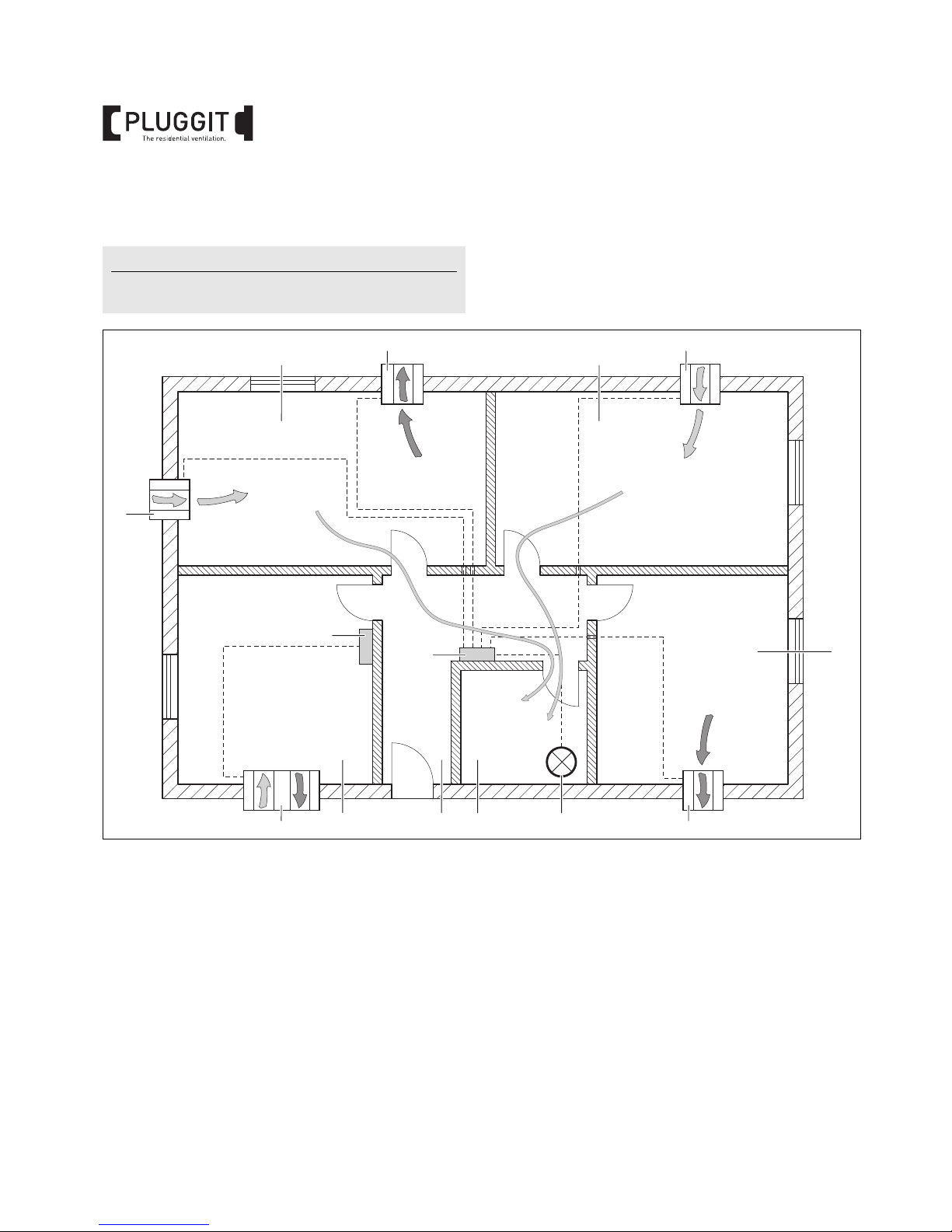
4.7. INSTALLATION TYPE SINGLE-ROOM
VENTILATION UNIT ICONVENT MONO,
ICONVENT
DUO AND EXHAUST AIR VAN
Sample installation
1 Single-roo
m ventilation unit iconVent Mono
2 Single-roo
m ventilation unit iconVent Duo
3 Exhaust air fan according
to DIN 18017-3
4 Regulation
5 Supp
ly air room, for example, living and dining room
6 Supp
ly air room, for example, bedroom
7 Suppl
y air room, for example, guest room or
children's room
8 Exhaust
air room, for example, bathroom without window
9 Exhaust air room,
for example kitchen with window
10 Overflow area, f
or example, corridor or hall
The installation type with single
-room ventilation unit
iconVent Mono (1), iconVent Duo (2) and exhaust air fan (3)
is carried out correspondingly.
Example:
The exhaust air fan (3) is also connected with the
re
gulation (4), which also controls the single-room ventilation units (1) for the cross ventilation. The supply air volume
f
low of the single-room ventilation units (1) must be adjusted
respectively +30 m³/h higher, as soon as and as long as the
e
xhaust air fan (3) is in operation.
Thus, in total the 60 m³/h (VAB) exhaust air volume flow of the
exhaust air fan (3) is compensates and hear recovery is guaranteed.
The single-room ventilation units iconVent Mono (1) and
i
conVent Duo (2) can be adjusted to various additional volume
flows depending on the number of installed units.
The single-room ventilation unit iconVent Duo (2) in the
ki
tchen (9) continues to run in balance.
Note:
The described installation type is valid for inside bathrooms without window according to DIN
18017-3.
1
1
4
4
7
5 6
2
8 3
V
AB
3
= 60m /h
+/-0%
109
1
1
3
+30m /h
3
+30m /h
M+P-26A-1108
Page 15
13
BIA Single room ventilation unit iconVent Mono and iconVent Duo
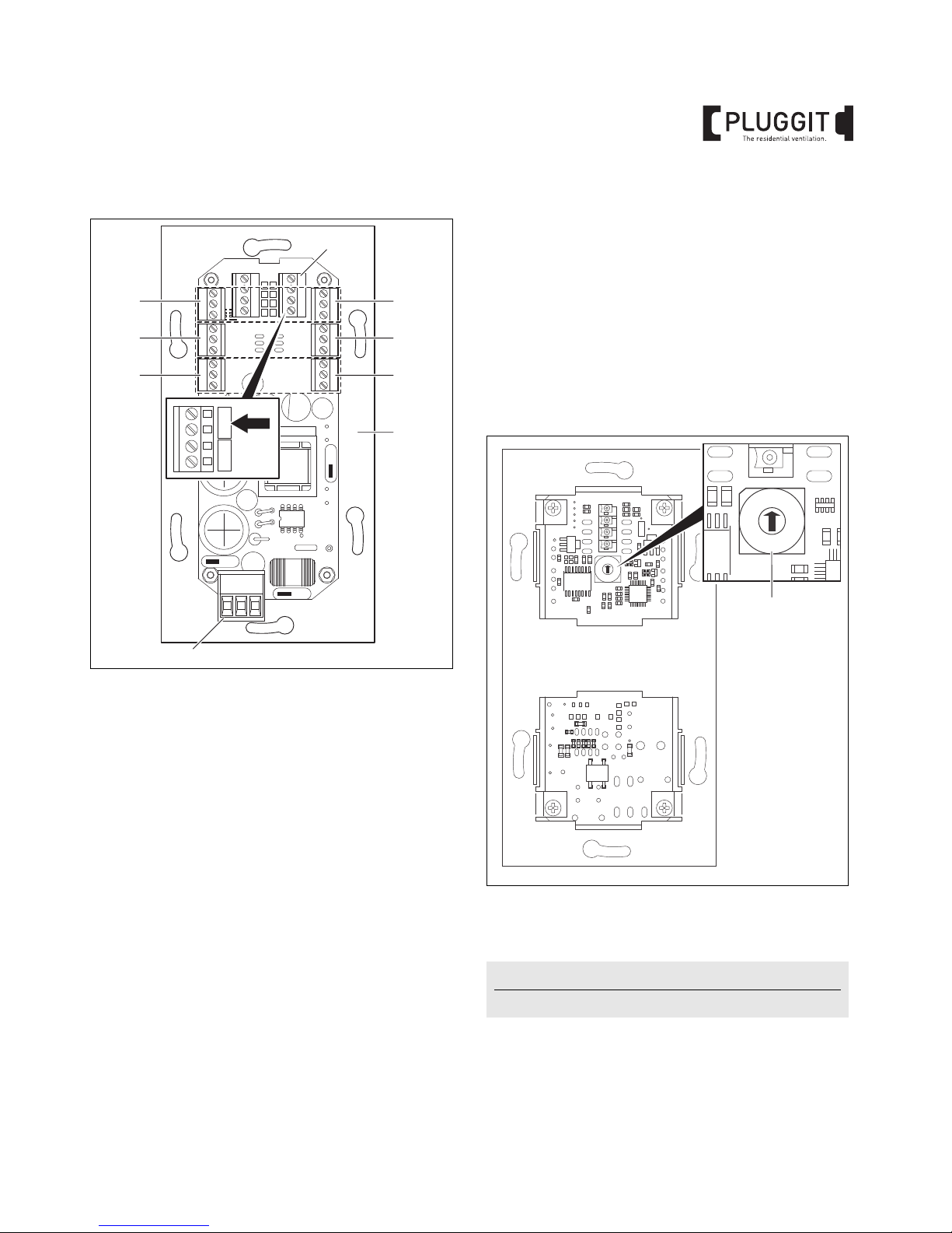
4.8. REGULATION
1 Plug connector functional unit 1 (exhaust air)
2 Plug conn
ector functional unit 2 (supply air)
3 Plug conn
ector functional unit 3 (exhaust air)
4 Plug conn
ector functional unit 4 (supply air)
5 Plug conn
ector functional unit 5 (exhaust air)
6 Plug conn
ector functional unit 6 (supply air)
7 External entry, potential-
free 0/10 V
Plug the time-delay relay at the connection E1 (arrow).
8 Regulatio
n
The single-room ventilation units iconVent Mono and
iconVent
Duo as well as the exhaust air fan are controlled by
a regulation ICVC (8).
This has six plug connectors (1-6) for the connection of the
single-roo
m ventilation units as well as one plug
connector (7) for the connection of the exhaust air fan.
The connection of two single-room units iconVent Mono or
on
e iconVent Duo always shall be carried out at the horizon-
tally opposite plug connectors.
For the single-room ventilation units, which are always installed in pairs in the exhaust air rooms, for example,
kitchen,
bathroom and toilet with window, always both
upper plug connectors (1) and (2) shall be used.
As supply line for the supply voltage of the regulation (8) an
insulated cable 3 x 1.5 m
m² shall be applied.
Depending on the cable length the following insulated
c
ables are applied as control wire for the single-room
ventilation units:
• Cable length 0-12 m: 3 x 0.25 mm²
• Cable length 12-20 m: 3 x 0.6 mm²
• Cable length 20-25 m: 3 x 0.8 mm²
The regulation is carried out by the rotary switch (10).
Depending on the required air volume flow various operating modes can be adjusted, see from page 14 onwards.
2
7
4
6
E1 E2
1
3
5
3x1,5mm
2
8
M+P-26A-1210
Note:
Level C-F are without function assignment.
0
F
E
D
C
B
A
9
8
7
6
5
4
3
2
1
10
M+P-26A-1111
Page 16
14
BIA Single room ventilation unit iconVent Mono and iconVent Duo
4.8.1. Regulation schemes
Legend
1 icon
Vent regulation
2 Additional volume
flow supply air
3 Additional volume
flow exhaust air
Example connection level 2
1 Conne
ction insulated cable
• Cable length 0-12 m: 3 x 0.25 mm²
• Cable length 12-20 m: 3 x 0.6 mm²
• Cable length 20-25 m: 3 x 0.8 mm²
Analogous to the below described example of level 2 the
conne
ction of all levels is carried out.
531
642
+ 0
- 0
1
2
3
M+P-26A-1180
531
642
+ 0
- 0
+ 0
- 0
+10m³/h
- 0
+10m³/h
- 0
+ 0
- 0
+ 0
- 0
Example:
children’s room
3 x 1,5mm² /
230V /
50Hz
Example:
Living room +10m
3
/h
additional volume flow
Example:
bedroom
Example:
Dining room +10m
3
/h
additional volume flow
Example:
kitchen
L
PE
N
1
M+P-26A-1309
Page 17
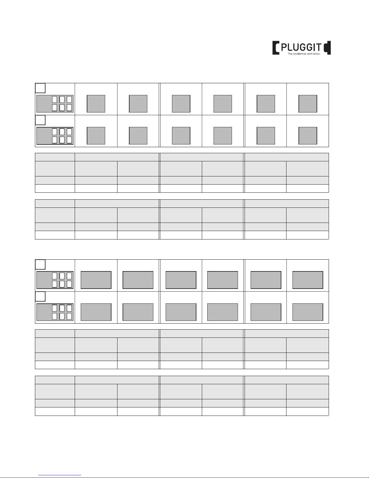
15
BIA Single room ventilation unit iconVent Mono and iconVent Duo
Level 0
Level 1
Rotation direction A Rotation direction A Rotation direction A
Plug
connector
Functional level 1Functional level 2Functional level 3Functional level 4Functional level 5Functional level
6
Position Supply air Exhaust air Supply air Exhaust air Supply air Exhaust air
Level 0 Balance Balance Balance Balance Balance Balance
Rotation direction B Rotation direction B Rotation direction B
Plug
connector
Functional level 1Functional level 2Functional level 3Functional level 4Functional level 5Functional level
6
Position Exhaust air Supply air Exhaust air Supply air Exhaust air Supply air
Level 0 Balance Balance Balance Balance Balance Balance
A
B
531
642
531
642
+ 0
- 0
+ 0
- 0
+ 0
- 0
+ 0
- 0
+ 0
- 0
+ 0
- 0
+ 0
- 0
+ 0
- 0
+ 0
- 0
+ 0
- 0
+ 0
- 0
+ 0
- 0
Rotation direction A Rotation direction A Rotation direction A
Plug
connector
Functional level 1Functional level 2Functional level 3Functional level 4Functional level 5Functional level
6
Position Supply air Exhaust air Supply air Exhaust air Supply air Exhaust air
Level 1 Balance Balance +5 % +/- 0 % +/- 0 % +5 %
Rotation direction B Rotation direction B Rotation direction B
Plug
connector
Functional level 1Functional level 2Functional level 3Functional level 4Functional level 5Functional level
6
Position Exhaust air Supply air Exhaust air Supply air Exhaust air Supply air
Level 1 Balance Balance +/- 0 % +5 % +5 % +/- 0 %
A
B
531
642
531
642
+ 0
- 0
+ 0
- 0
+ 5%
- 0
+ 0
- 0
+ 0
- 0
- 0
+ 5%
+ 0
- 0
+ 0
- 0
+ 0
- 0
+ 5%
- 0
- 0
+ 5%
+ 0
- 0
Page 18
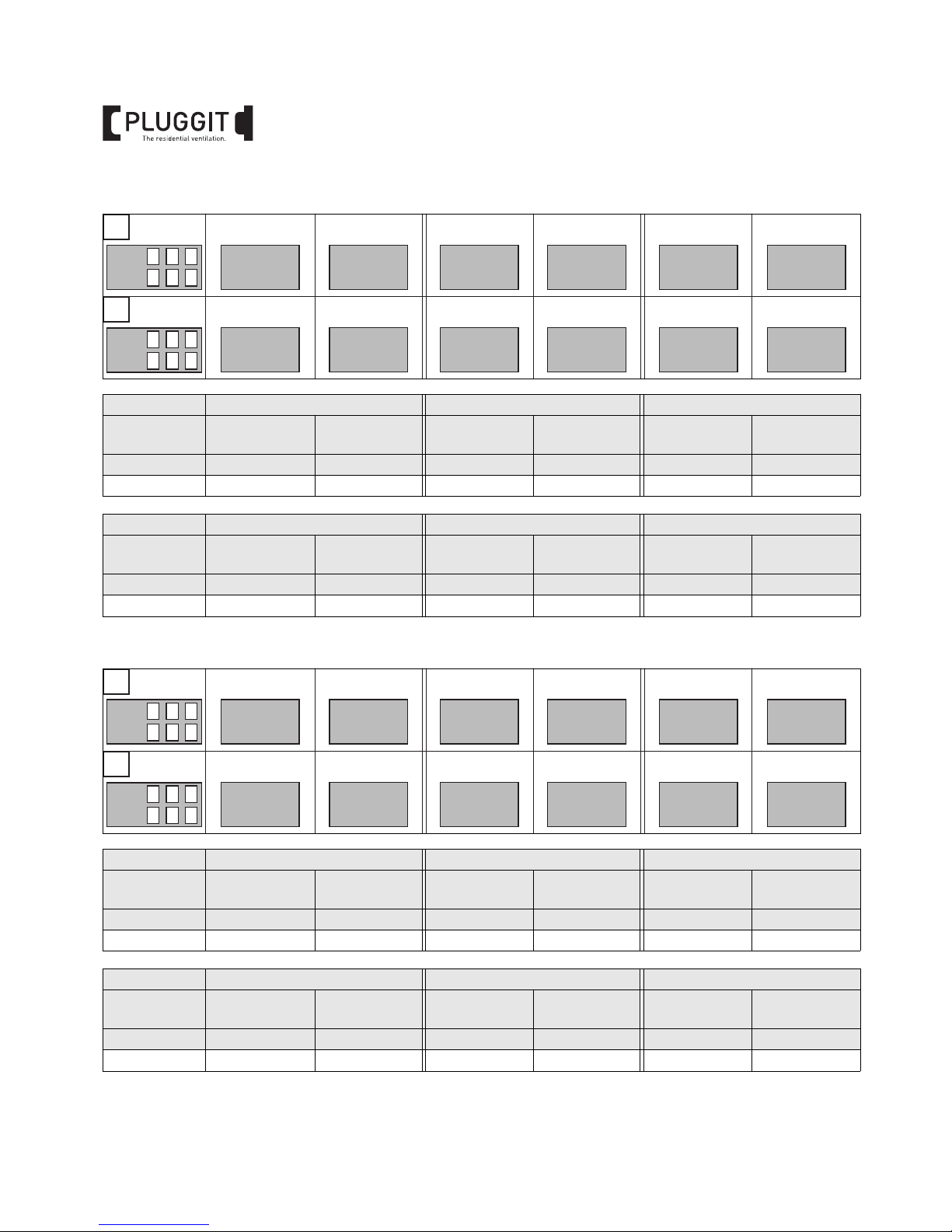
16
BIA Single room ventilation unit iconVent Mono and iconVent Duo
Level 2
Level 3
Rotation direction A Rotation direction A Rotation direction A
Plug
connector
Functional level 1Functional level 2Functional level 3Functional level 4Functional level 5Functional level
6
Position Supply air Exhaust air Supply air Exhaust air Supply air Exhaust air
Level 2 Balance Balance +10 m³/h +/- 0 % +10 m³/h +/- 0 %
Rotation direction B Rotation direction B Rotation direction B
Plug
connector
Functional level 1Functional level 2Functional level 3Functional level 4Functional level 5Functional level
6
Position Exhaust air Supply air Exhaust air Supply air Exhaust air Supply air
Level 2 Balance Balance +/- 0 % +10 m³/h +/- 0 % +10 m³/h
A
B
531
642
531
642
+ 0
- 0
+ 0
- 0
+ 10m³/h
- 0
+ 0
- 0
+ 10m³/h
- 0
+ 0
- 0
+ 0
- 0
+ 0
- 0
+ 0
- 0
+ 10m³/h
- 0
+ 0
- 0
+ 10m³/h
- 0
Rotation direction A Rotation direction A Rotation direction A
Plug
connector
Functional level 1Functional level 2Functional level 3Functional level 4Functional level 5Functional level
6
Position Supply air Exhaust air Supply air Exhaust air Supply air Exhaust air
Level 3 Balance Balance +12.5 m³/h +/- 0 % +12.5 m³/h +/- 0 %
Rotation direction B Rotation direction B Rotation direction B
Plug
connector
Functional level 1Functional level 2Functional level 3Functional level 4Functional level 5Functional level
6
Position Exhaust air Supply air Exhaust air Supply air Exhaust air Supply air
Level 3 Balance Balance +/- 0 % +12.5 m³/h +/- 0 % +12.5 m³/h
A
B
531
642
531
642
+ 0
- 0
+ 0
- 0
+ 12,5m³/h
- 0
+ 0
- 0
+ 12,5m³/h
- 0
+ 0
- 0
+ 0
- 0
+ 0
- 0
+ 0
- 0
+ 12,5m³/h
- 0
+ 0
- 0
+ 12,5m³/h
- 0
Page 19
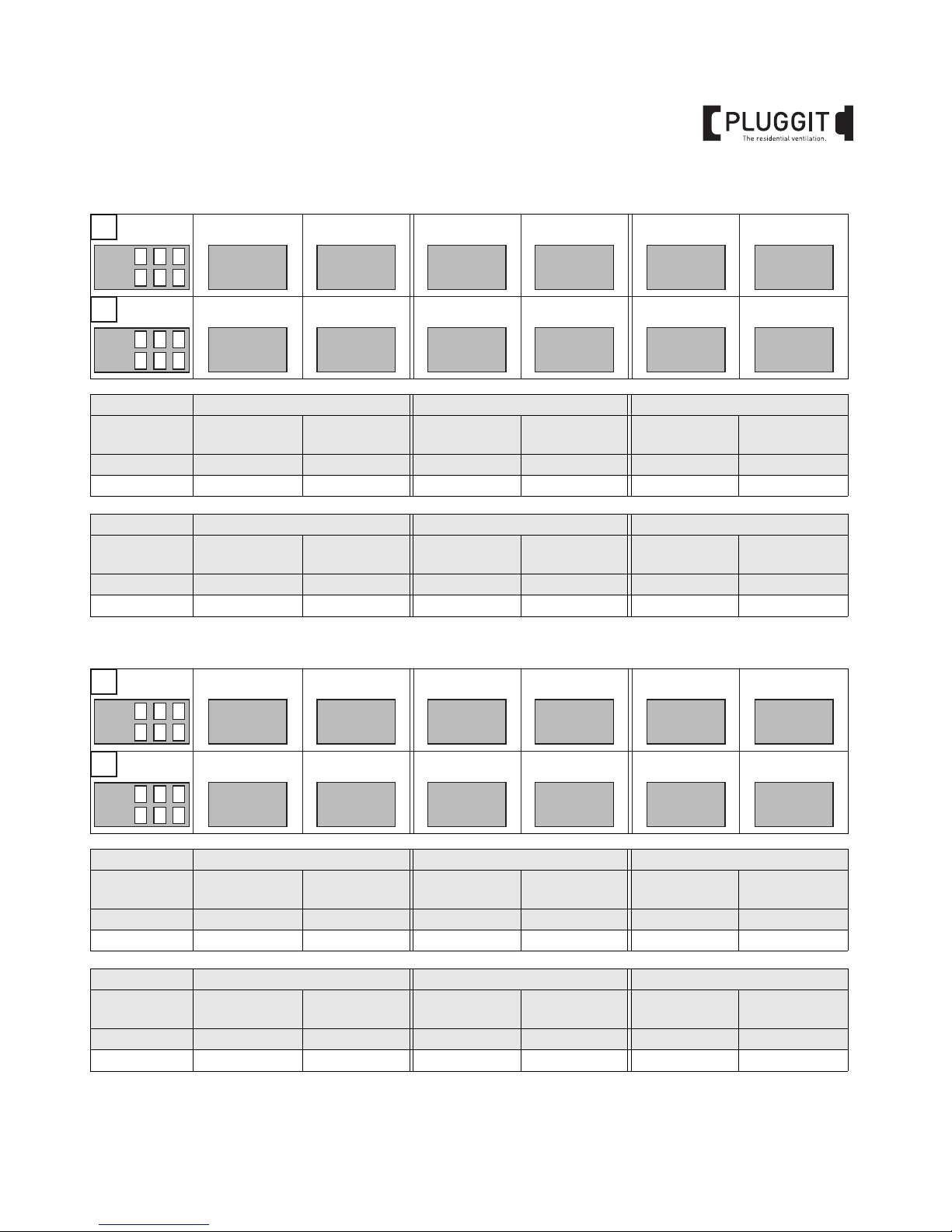
17
BIA Single room ventilation unit iconVent Mono and iconVent Duo
Level 4
Level 5
Rotation direction A Rotation direction A Rotation direction A
Plug
connector
Functional level 1Functional level 2Functional level 3Functional level 4Functional level 5Functional level
6
Position Supply air Exhaust air Supply air Exhaust air Supply air Exhaust air
Level 4 Balance Balance +15 m³/h +/- 0 % +15 m³/h +/- 0 %
Rotation direction B Rotation direction B Rotation direction B
Plug
connector
Functional level 1Functional level 2Functional level 3Functional level 4Functional level 5Functional level
6
Position Exhaust air Supply air Exhaust air Supply air Exhaust air Supply air
Level 4 Balance Balance +/- 0 % +15 m³/h +/- 0 % +15 m³/h
A
B
531
642
531
642
+ 0
- 0
+ 0
- 0
+ 15m³/h
- 0
+ 0
- 0
+ 15m³/h
- 0
+ 0
- 0
+ 0
- 0
+ 0
- 0
+ 0
- 0
+ 15m³/h
- 0
+ 0
- 0
+ 15m³/h
- 0
Rotation direction A Rotation direction A Rotation direction A
Plug
connector
Functional level 1Functional level 2Functional level 3Functional level 4Functional level 5Functional level
6
Position Supply air Exhaust air Supply air Exhaust air Supply air Exhaust air
Level 5 Balance Balance +20 m³/h +/- 0 % +20 m³/h +/- 0 %
Rotation direction B Rotation direction B Rotation direction B
Plug
connector
Functional level 1Functional level 2Functional level 3Functional level 4Functional level 5Functional level
6
Position Exhaust air Supply air Exhaust air Supply air Exhaust air Supply air
Level 5 Balance Balance +/- 0 % +20 m³/h +/- 0 % +20 m³/h
A
B
531
642
531
642
+ 0
- 0
+ 0
- 0
+ 20m³/h
- 0
+ 0
- 0
+ 20m³/h
- 0
+ 0
- 0
+ 0
- 0
+ 0
- 0
+ 0
- 0
+ 20m³/h
- 0
+ 0
- 0
+ 20m³/h
- 0
Page 20
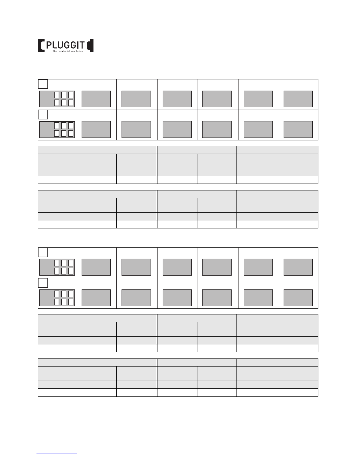
18
BIA Single room ventilation unit iconVent Mono and iconVent Duo
Level 6
Level 7
Rotation direction A Rotation direction A Rotation direction A
Plug
connector
Functional level 1Functional level 2Functional level 3Functional level 4Functional level 5Functional level
6
Position Supply air Exhaust air Supply air Exhaust air Supply air Exhaust air
Level 6 Balance Balance +30 m³/h +/- 0 % +30 m³/h +/- 0 %
Rotation direction B Rotation direction B Rotation direction B
Plug
connector
Functional level 1Functional level 2Functional level 3Functional level 4Functional level 5Functional level
6
Position Exhaust air Supply air Exhaust air Supply air Exhaust air Supply air
Level 6 Balance Balance +/- 0 % +30 m³/h +/- 0 % +30 m³/h
A
B
531
642
531
642
+ 0
- 0
+ 0
- 0
+ 30m³/h
- 0
+ 0
- 0
+ 30m³/h
- 0
+ 0
- 0
+ 0
- 0
+ 0
- 0
+ 0
- 0
+ 30m³/h
- 0
+ 0
- 0
+ 30m³/h
- 0
Rotation direction A Rotation direction A Rotation direction A
Plug
connector
Functional level 1Functional level 2Functional level 3Functional level 4Functional level 5Functional level
6
Position Supply air Exhaust air Supply air Exhaust air Supply air Exhaust air
Level 7 +10 m³/h +/- 0 % +10 m³/h +/- 0 % +10 m³/h +/- 0 %
Rotation direction B Rotation direction B Rotation direction B
Plug
connector
Functional level 1Functional level 2Functional level 3Functional level 4Functional level 5Functional level
6
Position Exhaust air Supply air Exhaust air Supply air Exhaust air Supply air
Level 7 +/- 0 % +10 m³/h +/- 0 % +10 m³/h +/- 0 % +10 m³/h
A
B
531
642
531
642
+ 10m³/h
- 0
+ 0
- 0
+ 10m³/h
- 0
+ 0
- 0
+ 10m³/h
- 0
+ 0
- 0
+ 0
- 0
+ 10m³/h
- 0
+ 0
- 0
+ 10m³/h
- 0
+ 0
- 0
+ 10m³/h
- 0
Page 21
19
BIA Single room ventilation unit iconVent Mono and iconVent Duo
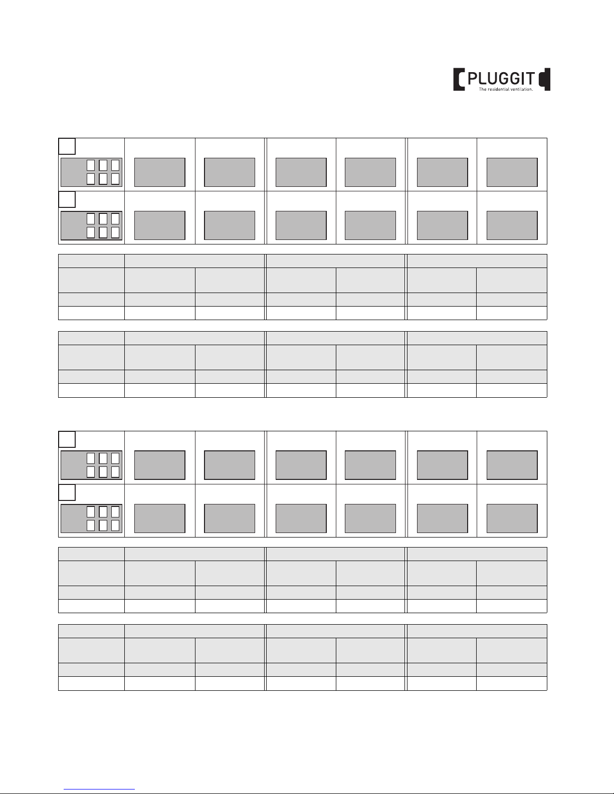
Level 8
Level 9
Rotation direction A Rotation direction A Rotation direction A
Plug
connector
Functional level 1Functional level 2Functional level 3Functional level 4Functional level 5Functional level
6
Position Supply air Exhaust air Supply air Exhaust air Supply air Exhaust air
Level 8 +12.5 m³/h +/- 0 % +12.5 m³/h +/- 0 % +12.5 m³/h +/- 0 %
Rotation direction B Rotation direction B Rotation direction B
Plug
connector
Functional level 1Functional level 2Functional level 3Functional level 4Functional level 5Functional level
6
Position Exhaust air Supply air Exhaust air Supply air Exhaust air Supply air
Level 8 +/- 0 % +12.5 m³/h +/- 0 % +12.5 m³/h +/- 0 % +12.5 m³/h
A
B
531
642
531
642
+ 12,5m³/h
- 0
+ 0
- 0
+ 12,5m³/h
- 0
+ 0
- 0
+ 12,5m³/h
- 0
+ 0
- 0
+ 0
- 0 - 0
+ 0
- 0
+ 12,5m³/h+ 12,5m³/h
- 0
+ 0
- 0
+ 12,5m³/h
- 0
Rotation direction A Rotation direction A Rotation direction A
Plug
connector
Functional level 1Functional level 2Functional level 3Functional level 4Functional level 5Functional level
6
Position Supply air Exhaust air Supply air Exhaust air Supply air Exhaust air
Level 9 +15 m³/h +/- 0 % +15 m³/h +/- 0 % +15 m³/h +/- 0 %
Rotation direction B Rotation direction B Rotation direction B
Plug
connector
Functional level 1Functional level 2Functional level 3Functional level 4Functional level 5Functional level
6
Position Exhaust air Supply air Exhaust air Supply air Exhaust air Supply air
Level 9 +/- 0 % +15 m³/h +/- 0 % +15 m³/h +/- 0 % +15 m³/h
A
B
531
642
531
642
+ 15
m³/h
- 0
+ 0
- 0
+ 15
m³/h
- 0
+ 0
- 0
+ 15
m³/h
- 0
+ 0
- 0
+ 0
- 0
+ 15
m³/h
- 0
+ 0
- 0
+ 15
m³/h
- 0
+ 0
- 0
+ 15
m³/h
- 0
Page 22
20
BIA Single room ventilation unit iconVent Mono and iconVent Duo
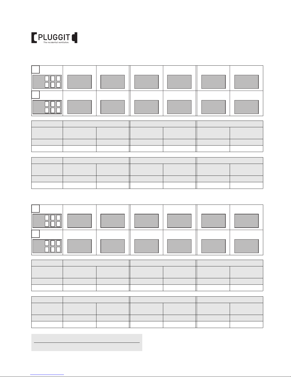
Level A
Level B
Rotation direction A Rotation direction A Rotation direction A
Plug
connector
Functional level 1Functional level 2Functional level 3Functional level 4Functional level 5Functional level
6
Position Supply air Exhaust air Supply air Exhaust air Supply air Exhaust air
Level A +20 m³/h +/- 0 % +20 m³/h +/- 0 % +20 m³/h +/- 0 %
Rotation direction B Rotation direction B Rotation direction B
Plug
connector
Functional level 1Functional level 2Functional level 3Functional level 4Functional level 5Functional level
6
Position Exhaust air Supply air Exhaust air Supply air Exhaust air Supply air
Level A +/- 0 % +20 m³/h +/- 0 % +20 m³/h +/- 0 % +20 m³/h
A
B
531
642
531
642
+ 20m³/h
- 0
+ 0
- 0
+ 20m³/h
- 0
+ 0
- 0
+ 20m³/h
- 0
+ 0
- 0
+ 0
- 0
+ 20m³/h
- 0
+ 0
- 0
+ 20m³/h
- 0
+ 0
- 0
+ 20m³/h
- 0
Rotation direction A Rotation direction A Rotation direction A
Plug
connector
Functional level 1Functional level 2Functional level 3Functional level 4Functional level 5Functional level
6
Position Supply air Exhaust air Supply air Exhaust air Supply air Exhaust air
Level B +30 m³/h +/- 0 % +30 m³/h +/- 0 % +30 m³/h +/- 0 %
Rotation direction B Rotation direction B Rotation direction B
Plug
connector
Functional level 1Functional level 2Functional level 3Functional level 4Functional level 5Functional level
6
Position Exhaust air Supply air Exhaust air Supply air Exhaust air Supply air
Level B +/- 0 % +30 m³/h +/- 0 % +30 m³/h +/- 0 % +30 m³/h
A
B
531
642
531
642
+ 30m³/h
- 0
+ 0
- 0
+ 30m³/h
- 0
+ 0
- 0
+ 30m³/h
- 0
+ 0
- 0
+ 0
- 0
+ 30m³/h
- 0
+ 0
- 0
+ 30m³/h
- 0
+ 0
- 0
+ 30m³/h
- 0
Note:
Level C-F are without function assignment.
Page 23
21
BIA Single room ventilation unit iconVent Mono and iconVent Duo
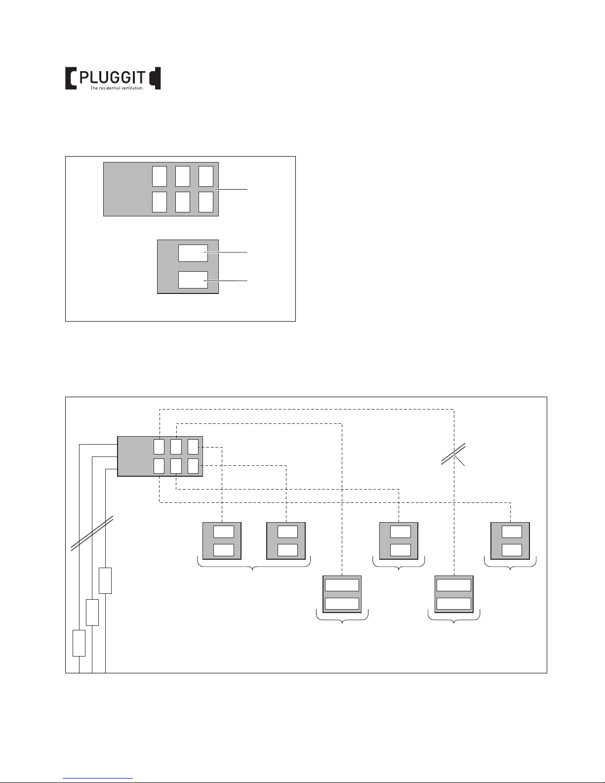
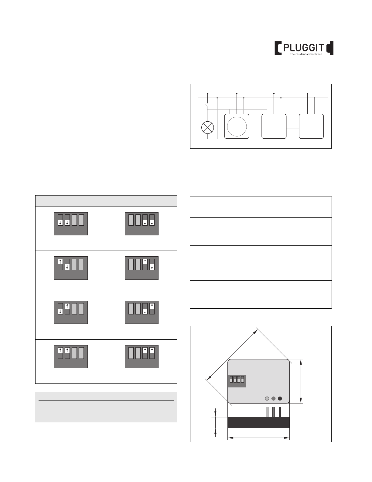
4.9. TIME-DELAY RELAY
The time-delay relay 230 V AC with control input and
potential-free solid state relay exit is applied in connection
with an exhaust air fan on site.
As soon as the control input is triggered (room lighting is
switched
on), a timer is started for the start delay.
After the expiration of the star
t delay the output relay is
activated and connects both white connections of the timedelay relay with the single-room ventilation unit iconVent.
After the release of the control signal the time delay begins.
If d
uring a time delay the input is again triggered, this is only
considered when the adjusted start delay has been
achieved.
Dependent on the settings of the exhaust air fan on site the
start d
elay and stop delay must be adjusted in the time-
delay relay.
4.9.1. Connection diagram
1 Exhaust
air fan (on site)
2 Time-de
lay relay
3 Single-room ventilation unit
iconVent
4.9.2. Technical data
4.9.3. Measurements
Start delay Stop delay
0 seconds 6 minutes
45 seconds 10 minutes
60 seconds 15 minutes
120 seconds 21 minutes
Note:
The voltage supplied to the exit shall not exceed 8 V.
Install the time-delay relay as close to the regulation as
possible.
123 4
1234
1 2 3 4
1234
1234
1234
1234
1234
Supply voltage 230 V AC
Operating voltage sector 195-265 V AC
Power consumption
Stand
by at 230 V AC
330 mW
Input resistance 180 k
Ω
Maximum permissible
switching voltage at the exit
8 V
Maximum permissible load
current at th
e exit
100 mA
Output resistance 30
Ω
Connections pipes 5 x LiY 0,5 mm² (strands)
100 m length
L
N
S
123
M+P-26A-1244
123 4
35.0
58.5
11.0
49.0
M+P-26A-1245
Page 24

22
BIA Single room ventilation unit iconVent Mono and iconVent Duo
5.1. NOTES FOR INSTALLATION
• The installation stones ICVS and installation
sleeves ICVH for the installation of the single-room
v
entilation units have to be installed in the outside walls,
see page 23.
• The shell construction must be concluded and the complete wall structure must be terminated.
• A coordination with the electrician has to be made that
the electric
lines are integrated in the groove of the
installation stones ICVS or installation sleeves ICVH and
are labeled with the corresponding room designation in
the provided double cavity wall flush-mounted socket
for the regulation.
• Depending on the necessary air exchange in each supply
and exhaust air room one or several single-room
ventilation u
nits can be installed.
• The correct settings of the air volume flows must be
conside
red. The air flow shall not be obstructed by fur-
niture, curtains or similar things.
• The single-room ventilation units iconVent Mono always
must be operate
d in pairs on a regulation.
• The single-room ventilation units must be freely accessible for all maintenance works.
• The single-room ventilation units shall only be taken
into operation
after terminating all installation works.
5. INSTALLATION (QUALIFIED STAFF)
Warning:
The installation of the single-room ventilation unit
shall only be implemented by qualified staff to avoid injuries or damages.
Note:
For the wall structure the Pluggit iconVent plaster
tissue ICV-PG must be integrated with the interior
plaster.
Page 25
23
BIA Single room ventilation unit iconVent Mono and iconVent Duo
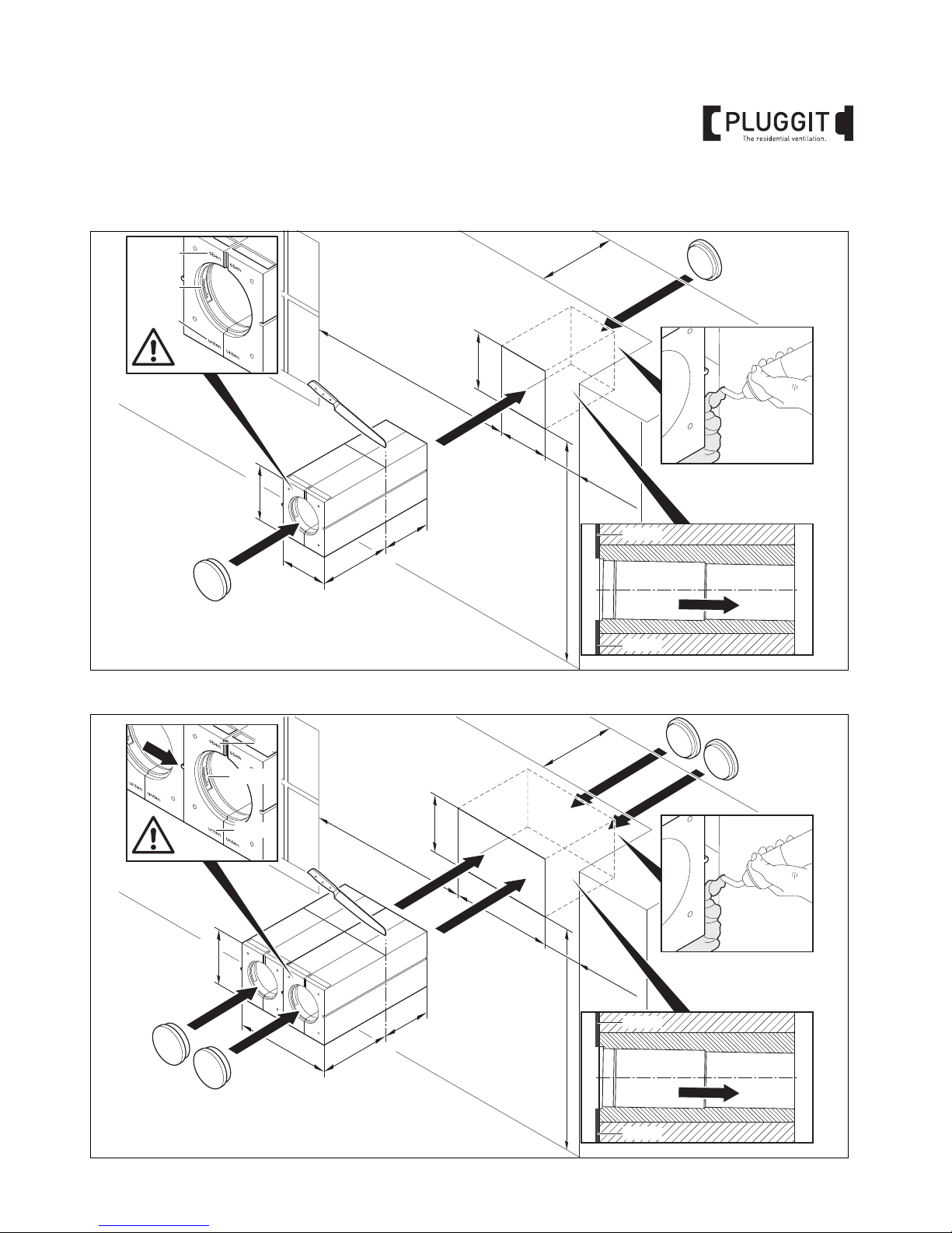
5.2. ASSEMBLE INSTALLATION STONE ICVS AND INSTALLATION SLEEVE ICVH
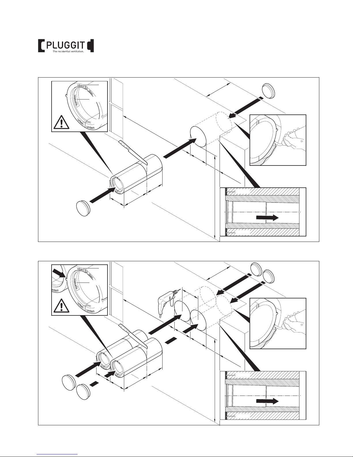
5.2.1. Installation stone ICVS for single-room ventilation unit iconVent Mono
5.2.2. Installation stone ICVS
for single-room ventilation unit iconVent Duo
unten
oben
oben
unten
1%
220 mm
min. 230 mm
min. 1,5 m
min. 150 mm
min. 285 mm
215 mm
min. 285 mm
min. 1,6 m
245 mm
min. 255 mm
Inside
Outside
Plaster
Plaster
M+P-26A-1313
up
down
Inside
unten
oben
oben
unten
unten
oben
oben
unten
1%
440 mm
min. 450 mm
min. 1,5 m
min. 150 mm
min. 285 mm
215 mm
min. 285 mm
min. 1,6 m
245 mm
min. 255 mm
Inside
Outside
Plaster
Plaster
M+P-26A-1314
up
down
Inside
Page 26
24
BIA Single room ventilation unit iconVent Mono and iconVent Duo
5.2.3. Installation sleeve ICVH for single-room ventilation unit iconVent Mono
5.2.4. Installation sleeve ICVH for single-room ventilation unit iconVent Duo
1%
Ø 198 mm
Ø 200 mm
min. 1,5 m
min. 150 mm
min. 285 mm
215 mm
min. 285 mm
min. 1,6 m
Inside
Outside
Plaster
Plaster
M+P-26A-1315
up
down
Inside
1%
Ø 198 mm
Ø 200 mm
min. 1,5 m
min. 150 mm
min. 285 mm
215 mm
min. 285 mm
min. 1,6 m
Ø 200 mm
Ø 198 mm
198 mm
Inside
Outside
Plaster
Plaster
M+P-26A-1316
up
down
Inside
Page 27
25
BIA Single room ventilation unit iconVent Mono and iconVent Duo
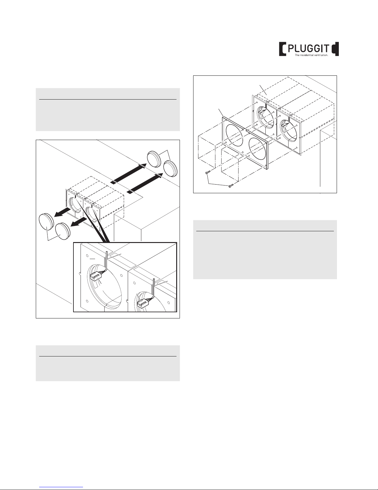
5.3. INSTALL SINGLE-ROOM VENTILATION UNIT
1. Remove construction protection (1) and (2).
2. Insert the plug (3) in groove (4).
3. Make drill holes for base plate inside (5) as described.
4. Attach base plate inside
(5) with screws (7).
Note:
The installation of the single-room ventilation unit
iconVent Mono and the installation of the single-room
ventilation unit with the installation sleeve ICVH is carried out correspondingly.
Note:
Do not dispose of construction protection (1) and (2).
These are required as manual locking mechanisms, for
example, at outside air contaminations.
unten
oben
oben
unten
unten
oben
oben
unten
oben
unt
oben
oben
oben
3
3
4
4
2
1
Outside wall
Inside wall
up
M+P-26A-1310
Note:
For the assembly of installation stones (6) use the insulation fixings contained in the scope of delivery and for
the
assembly of the installation sleeves ICVH use the
universal dowels contained in the scope of delivery.
A change to the iconVent design panel is possible with
identical drillings in the base plate.
unten
oben
unten
unten
oben
unten
oben
oben
7
6
5
M+P-26A-1166
Page 28
26
BIA Single room ventilation unit iconVent Mono and iconVent Duo
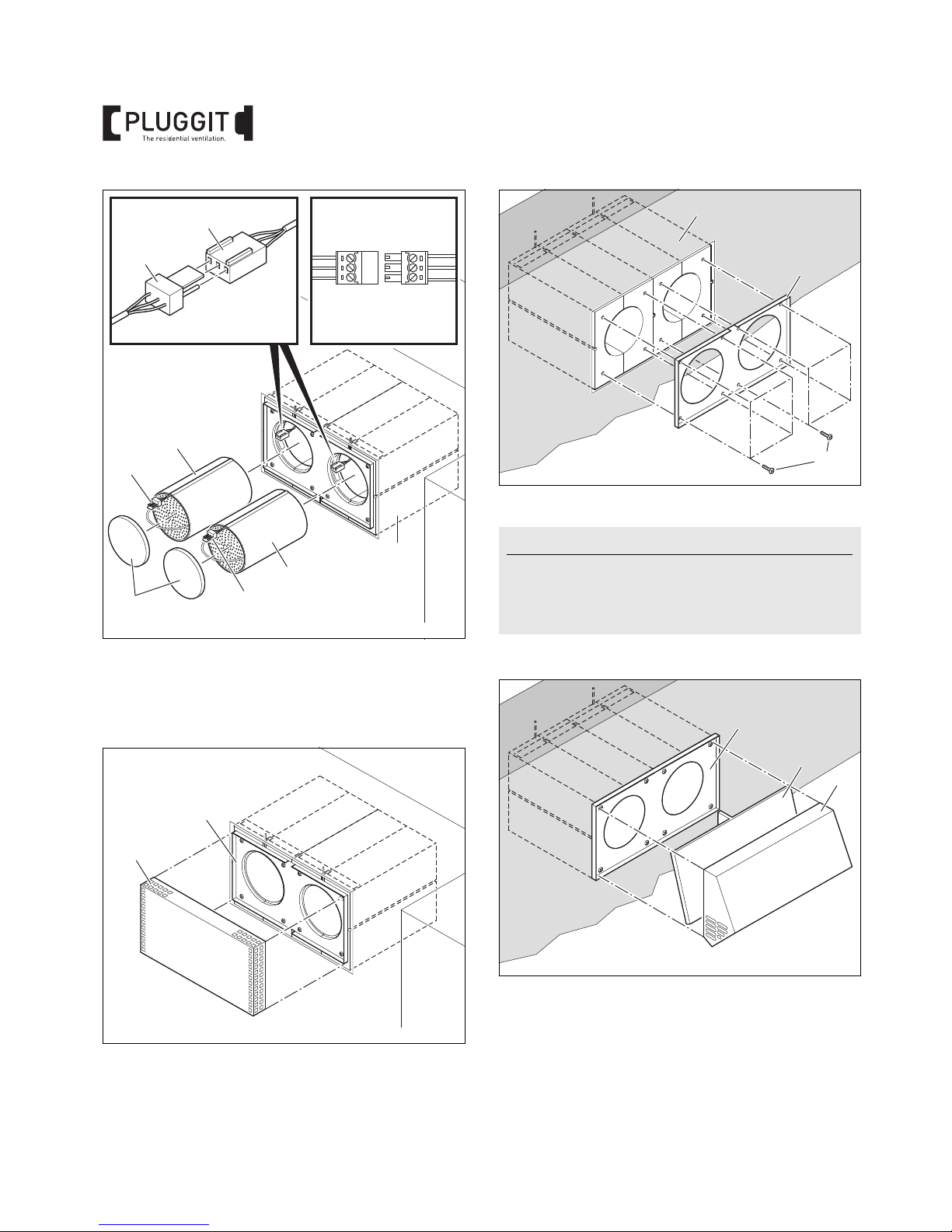
5. Insert functional units (8) until the stop in the installation
stones (6).
6. Connect plug (3) with plug (9).
7. Insert filter inside (10).
8. Attach inside panel (11) on base plate
inside (5).
9. Make drill holes for base plate outside (12) as described.
10. Attach base plate outside (12) with screws (13).
11. Insert insulation mat (14) in the groove of the base plate
ou
tside (12).
12. Attach weather protection grid (15) on the base plate
ou
tside (12).
unten
oben
unten
unten
oben
unten
oben
oben
10
9
8
3
+
red
blue
purple
-
s
9
9
8
6
M+P-26A-1311
unten
oben
unten
unten
oben
unten
5
11
M+P-26A-1168
Note:
For the assembly of installation stones (6) use the insulation fixings contained in the scope of delivery and for
the assembly of the installation sleeves ICVH use the
universal dowels contained in the scope of delivery.
6
12
13
M+P-26A-1248
12
14
15
M+P-26A-1206
Page 29
27
BIA Single room ventilation unit iconVent Mono and iconVent Duo
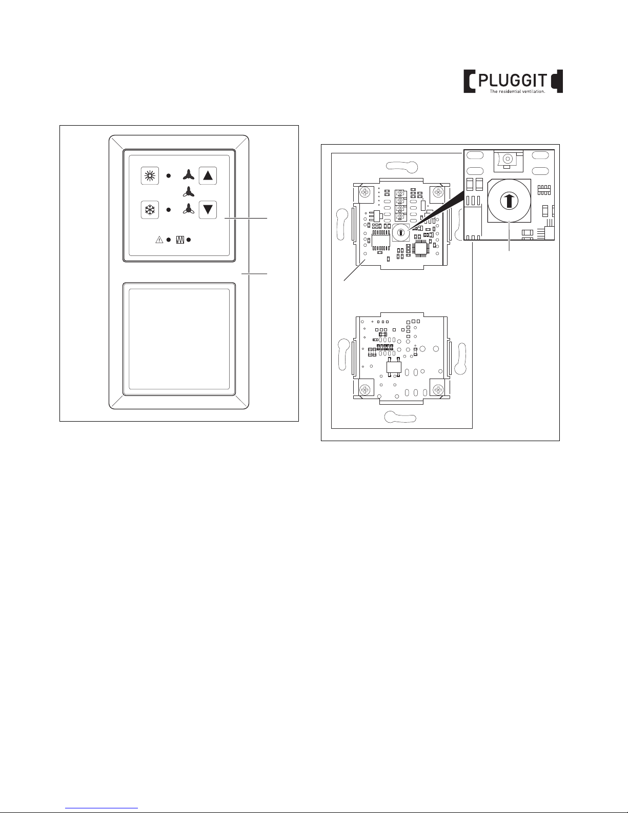
13. Insert regulation with control unit (16) in installed
double cavity wall flush-mounted socket (17).
5.4. INITIAL OPERATION
All installed regulations (1) which are required according to
the air volume flow, see from page 14 onwards.
16
17
M+P-26A-1207
0
F
E
D
C
B
A
9
8
7
6
5
4
3
2
1
2
1
M+P-26A-1113
Page 30
28
BIA Single room ventilation unit iconVent Mono and iconVent Duo
5.5. TECHNICAL DATA
5.5.1. Unit data
5.5.2. Regulation
5.5.3. Measurements
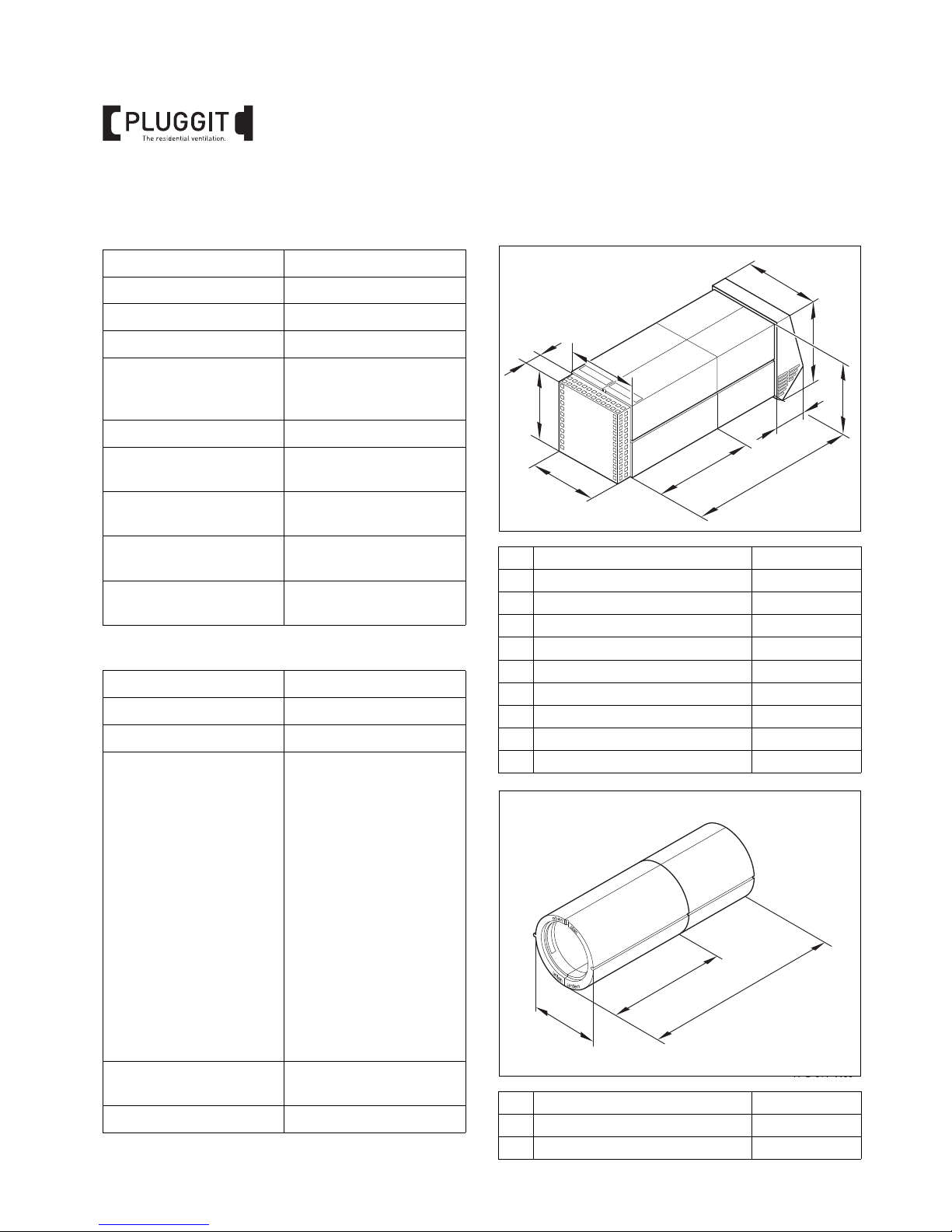
Single-room ventilation unit iconVent Mono
Weight iconVent Mono approx. 5 kg incl. panels
Weight iconVent Duo approx. 10 kg incl. panels
Supply voltage 12 V DC
Energy consumption level 3 6.7 W
Air volume flow Level 1: 18 m³/h
Level 2: 30 m³/h
Level 3: 48 m³/h
Rotation speed control 3-stage adjustable in advance
Fan Axial fan
1 piece per functional unit
Heat exchanger Technical ceramic in
hexagonal structure
Filter Filter quality G3 (inside)
Filter quality G3 (outside)
Heat provision level
a
ccording to DIBt-approval
approx. 92 %
Supply voltage 230 V AC, 50 Hz
Overall performance until 24 W
Control voltage 12 V
Recommended performance cross section
•3 x 1.5 mm²
for supply voltage
•3 x 0.25 mm²
(at cable length 0-12 m)
for con
trol line per func-
tional unit
•3 x 0.6 mm²
(at cable length 12-20 m)
for con
trol line per func-
tional unit
•3 x 0.8 mm²
(at cable length 20-25 m)
for con
trol line per func-
tional unit
• min. 2 x 0.6 mm²
for external entry
Connections six functional units,
at maximum
External entry 1
A Total depth installation stone 500 mm
B Minimum installation depth 285 mm
C Width installation stone 220 mm
D Height installation stone 245 mm
E Depth inside panel 50 mm
F Width inside panel 205 mm
G Height inside panel 200 mm
H Depth weather protection grid 116 mm
I Width weather protection grid 239 mm
J Height weather protection grid 290 mm
A Overall depth installation sleeve 500 mm
B Minimum installation depth 285 mm
C Diameter installation sleeve 198 mm
unten
oben
oben
unten
J
I
F
B
A
G
E
C
D
H
M+P-26A-1208
C
B
A
Page 31
29
BIA Single room ventilation unit iconVent Mono and iconVent Duo
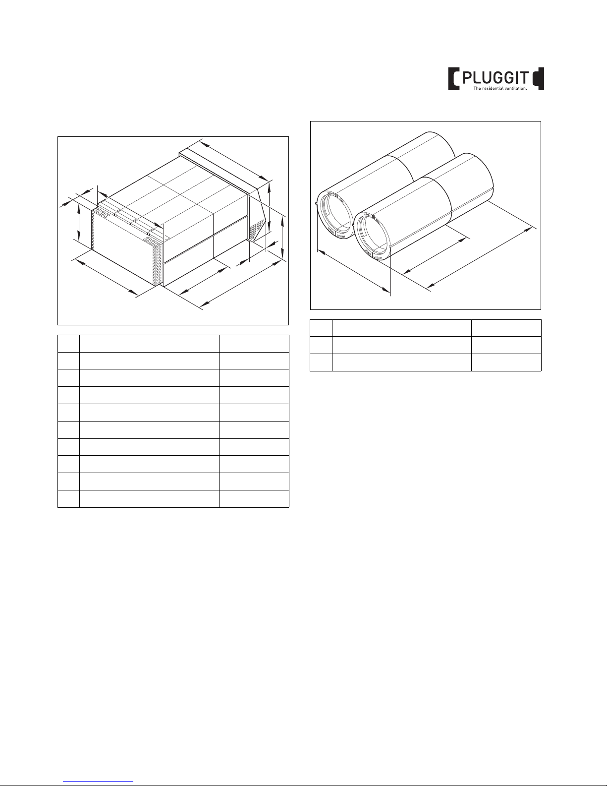
Single-room ventilation unit iconVent Duo
A Total depth installation stone 500 mm
B Minimum installation depth 285 mm
C Width installation stone 440 mm
D Height installation stone 245 mm
E Depth inside panel 50 mm
F Width inside panel 410 mm
G Height inside panel 200 mm
H Depth weather protection grid 118 mm
I Width weather protection grid 459 mm
J Height weather protection grid 289 mm
unten
oben
unten
unten
oben
unten
J
I
F
B
A
H
G
E
C
D
M+P-26A-1209
A Overall depth installation sleeve 500 mm
B Minimum installation depth 285 mm
C Diameter installation sleeve 396 mm
C
B
A
M+P-26A-1183
Page 32
30
BIA Single room ventilation unit iconVent Mono and iconVent Duo
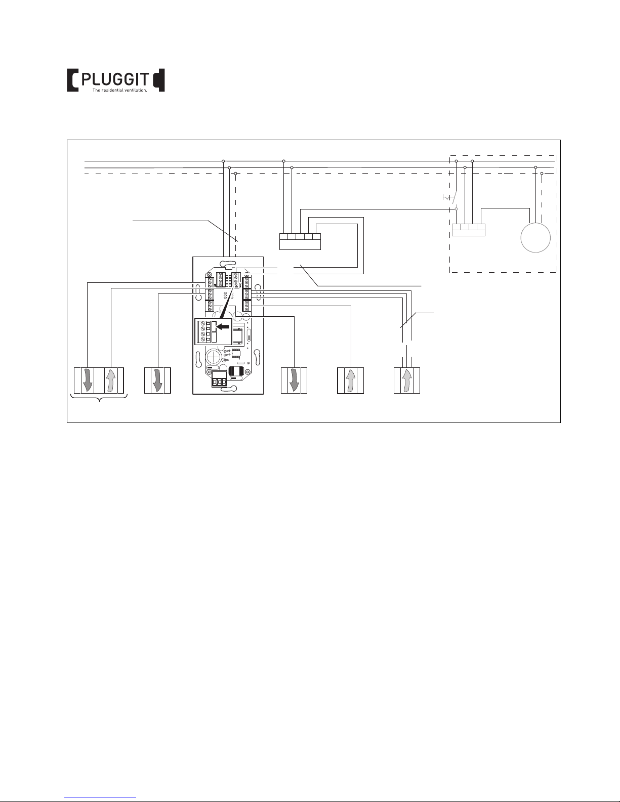
5.5.4. Basic wiring diagram, electrical
1 Connection insulated cable
• Cable length 0-12 m: 3 x 0.25 mm²
• Cable length 12-20 m: 3 x 0.6 mm²
• Cable length 20-25 m: 3 x 0.8 mm²
Plug the time-delay relay at the connection E1 (arrow).
12V
0V/10V potential-free min. 2x0,6 mm
2
230V/50Hz Min. 3x1,5 mm
2
Pluggit Relay
L
N
PE
Exhaust air fan on site
with follow-up.
Please consider connection
plan of the exhaust air fan.
iconVent Mono
e.g. dining room
iconVent Mono
e.g. children’s room
iconVent Mono
e.g. bedroom
iconVent Mono
e.g. living room
iconVent Duo
e.g. kitchen, bathroom
M
1.
Time-delay relay
red +
purple S
blue -
white
white
E1 E2
1
1
2
3
6
5
4
M+P-26A-1312
Page 33
31
BIA Single room ventilation unit iconVent Mono and iconVent Duo
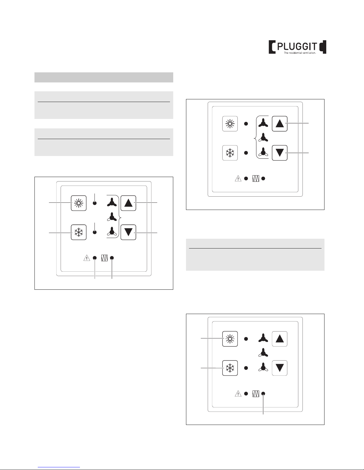
6.1. OVERVIEW REGULATION
1 Increase fan stage
2 Reduce fan stage
3 Switch on winter operation
Approximately each 80 seconds the ro
tation direction
of the fans in the functional units changes.
4 Switch on summer
operation
A change of rotation direction and heat recover do not
take plac
e.
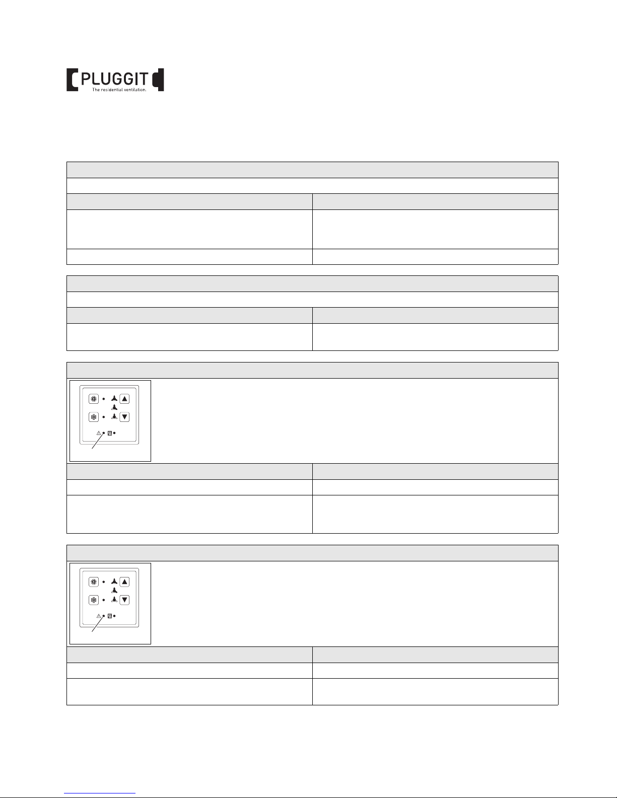
5 LED
s for fan stages 1-3
6 LED lights
at switched on winder operation.
7 LED lights
at switched on summer operation.
8 LED flashe
s without interruption if a change of filter is
required.
9 L
ED flashes three times if there is a communication
problem with the functional units.
LED flashes six times if there is a system error.
6.2. INCREASE/ REDUCE FAN LEVEL
On demand the fan level can be manually increased or
reduced.
Press key (1) to increase or key (2) to reduce the fan level.
C
orrespondingly to the fan level the number of LEDs (3)
flashes.
6.3. RESET FILTER ALARM
The filter alarm (1) flashes in a factory-adjusted manner
after 180 days. The filter must be cleaned or changed and
the filter alarm must be reset.
Keep key (2) and (3) pressed.
The filter alarm is reset. The LED (1) expires.
6. OPERATION (USER)
Note:
All descriptions in this chapter "operation" may be carried out by the user.
Note:
All settings of a regulation are taken over for all singleroom ventilation units connected with this regulation.
1
5
2
4
3
9
6
7
8
M+P-26A-1114
Note:
In case of operation of the single-room ventilation unit at
fan level 3 the unit changes automatically to fan level 2
after 2 hours.
1
3
2
M+P-26A-1117
2
3
1
M+P-26A-1116
Page 34
32
BIA Single room ventilation unit iconVent Mono and iconVent Duo
6.4. ERROR CORRECTION
6.4.1. Disturbances
Disturbance
The air exchange is too low.
Potential reason Remedy
The filters are clogged.
• Control filter of contamination
and, if necessary, change
it, see page 34.
• Reset filter alarm.
The adjusted fan level is too low. If necessary, adjust higher fan level, see page 31.
Disturbance
A single-room ventilation unit causes too many noises and vibrates.
Potential reason Remedy
A fan has an unbalance. Request customer service of the specialized company and
have the functional unit controlled and, if necessary changed.
Disturbance
The LED (1) flashes three times.
One or several single-room ventilation units do not work anymore.
The fans do not rotate.
Potential reason Remedy
Line voltage is interrupted. Re-establish line voltage.
There is a communication problem. Request customer service of the specialized company and
hav
e functional unit or fans controlled and, if necessary,
changed.
Disturbance
The LED (1) flashes six times.
A regulation does not work.
Potential reason Remedy
Line voltage is interrupted. Re-establish line voltage.
There is a system error. Request customer service of the specialized company. Have
regulation
group controlled and, if necessary, changed.
1
M+P-26A-1184
1
M+P-26A-1184
Page 35
33
BIA Single room ventilation unit iconVent Mono and iconVent Duo
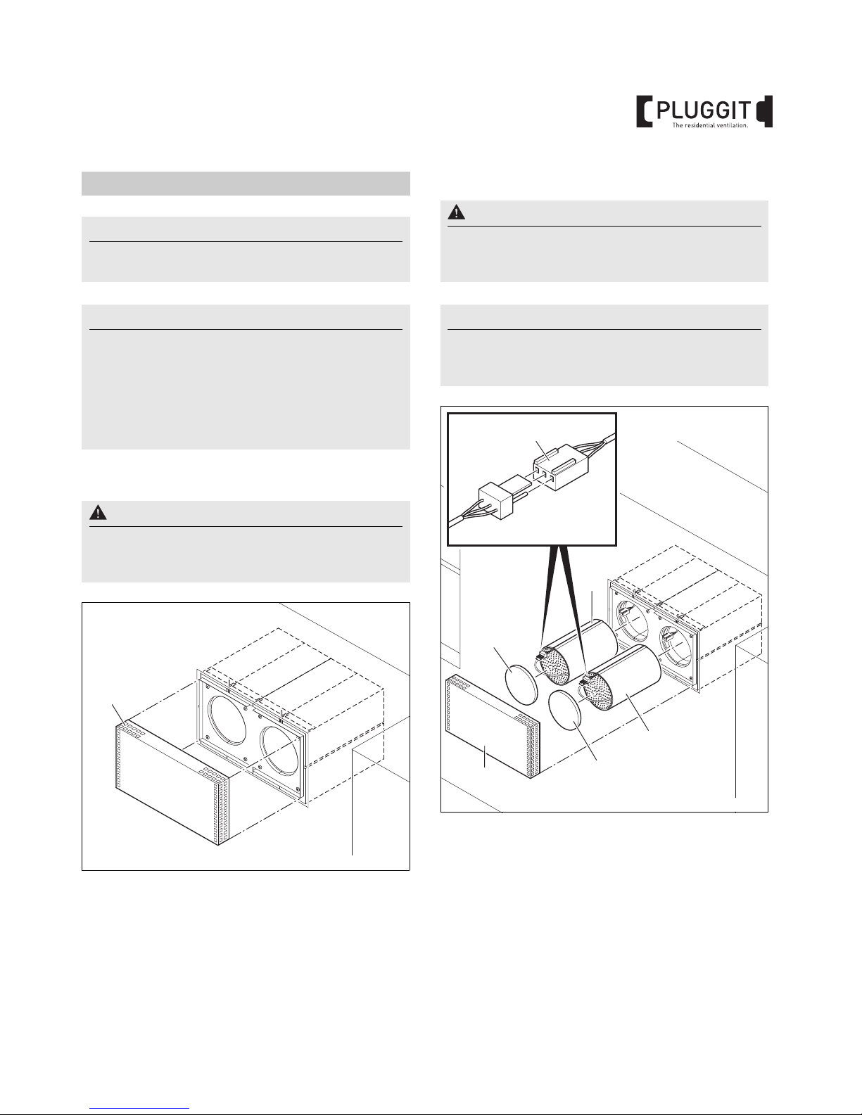
7.1. CLEAN INSIDE PANEL
1. Remove inside panel (1).
2. Clean inside panel (1) with
a damp cloth and neutral
cleaning agent.
3. The installation is carried out in reverse order.
7.2. CLEAN CERAMIC HEAT EXCHANGER
1. Remove inside panel (1).
2. Take out filter (2).
3. Pull out plug (3).
4. Pull out functional units (4).
7. MAINTENANCE (USER)
Note:
All descriptions in this chapter "maintenance" may be
implemented by the user.
Note:
All maintenance works shall be carried out for the
single-room ventilation units iconVent Mono and
iconVent Duo.
The following descriptions are demonstrated on the
basis of the example of a single-room ventilation unit
iconVent Duo and are implemented for the iconVent
Mono correspondingly.
Risk of injury:
Before all cleaning works disconnect all poles of the
single-room ventilation unit from the power supply,
otherwise it can cause injuries.
unten
oben
unten
unten
oben
unten
1
M+P-26A-1173
Risk of injury:
Before all cleaning works disconnect all poles of the
single-room ventilation unit from the power supply,
otherwise it can cause injuries.
Note:
Control and clean the ceramic heat exchanger for contamination each 12 months.
Only use warm water for cleaning.
unten
oben
unten
unten
oben
unten
oben
oben
3
2
4
1
2
4
M+P-26A-1174
Page 36
34
BIA Single room ventilation unit iconVent Mono and iconVent Duo
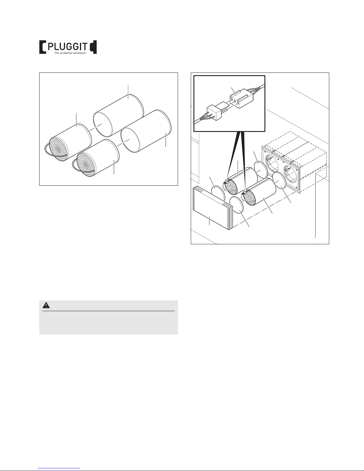
5. Ceramic heat exchanger (5) out of functional units (4),
soak it with warm water and then drain entire water.
6. The installation is carried out in reverse order.
7.3. CLEAN/ CHANGE FILTER
By means of the installed filters the air is cleaned from dirt
particles and the contamination of the heat exchanger is
prevented.
The operation of the single-room ventilation unit without
filter can im
ply an increased contamination in the heat
exchanger and of the fan, so that a hygienic operation is not
guaranteed.
Control the filter inside and outside approximately each six
months and
change them at least once per year.
1. Remove inside panel (1).
2. Take out filter (2) and clean or change it.
3. Pull out plug (3).
4. Pull out functional units (4).
5. Take out filter (5) and clean and change it.
6. Reset filter alarm, see page 31.
7. The installation is carried out in reverse order.
Risk of injury:
Before all cleaning works disconnect all poles of the
single-room ventilation unit from the power supply,
otherwise it can cause injuries.
4
4
5
5
M+P-26A-1109
unten
oben
unten
unten
oben
unten
oben
oben
3
2
5
4
1
2
4
5
M+P-26A-1175
Page 37

35
BIA Single room ventilation unit iconVent Mono and iconVent Duo
8.1. DECOMMISSIONING AT EXTENSION
The decommissioning may only be carried out by
qualified staff.
• Disconnect plant from mains voltage.
• Disconnect all poles of the plan
t from the power.
8.2. PACKAGING
The transport and protection packaging is produced from
reusable materials.
All packaging materials shall be dispose
d off according to
the local stipulations.
8.3. OLD UNIT
The single-room ventilation units contain valuable materials and substances, which shall not get into the residual
waste. The old units can be transfe
rred to a local recycling
operation for reutilization.
8. DECOMMISSIONING/DISPOSAL
Page 38
www.pluggit.com
PLUGGIT GmbH | Valentin-Linhof-Straße 2 | 81829 Munich | Germany
Telephone +49 89 411125-0 | Fax +49 89 411125-100
Pluggit Avent AP190/AP310/AP460 Ventilation Units
PluggLine Design Floor-Mounted Air Diffuser
PluggVoxx Air Processing
AeroFresh Plus Air Humidification
V02.02/15 M-BIA-iconVent-E
Further good ideas of
 Loading...