

Page 1

FCC WARNING STATEMENT
THIS DEVICE COMPLIES WITH PART 15 OF THE FCC RULES. OPERATION IS SUBJECT TO THE
FOLLOWING TWO CONDITIONS: (1) THIS DEVICE MAY NOT CAUSE HARMFUL INTERFERENCE,
AND (2) THIS DEVICE MUST ACCEPT ANY INTERFERENCE RECEIVED, INCLUDING
INTERFERENCE THAT MAY CAUSE UNDESIRED OPERATION.
NOTE: THE GRANTEE IS NOT RESPONSIBLE FOR ANY CHANGES OR MODIFICATIONS NOT
EXPRESSLY APPROVED BY THE PARTY RESPONSIBLE FOR COMPLIANCE. SUCH
MODIFICATIONS COULD VOID THE USER’S AUTHORITY TO OPERATE THE EQUIPMENT.
RFID Locking Device
User Manual version 1.0
Table of Contents
1. Overview ............................................................................................................................................... 2
2. Hardware Installation ........................................................................................................................... 3
3. Operation .............................................................................................................................................. 3
4. Battery Replacement ............................................................................................................................ 3
Page 2
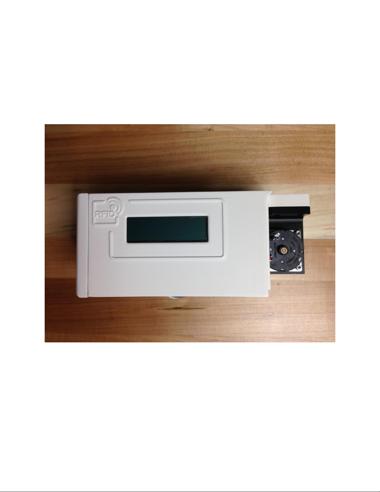
1. OVERVIEW
The RFID Locking Device enables authorized access to capital equipment using PNP Robotics RFID cards.
The device shall remain in a locked state while idle, prohibiting access to capital equipment, until
reading a PNP Robotics RFID card with a sufficient number of remaining uses, i.e. an active card. Once
reading an active card, the RFID Locking Device shall enter an unlocked state for a pre-specified period
of time, enabling access to the capital equipment, and decrement the number of remaining uses. The
RFID Locking Device shall re-engage the lock once usage has expired.
Fig. 1. RFID Locking Device
Page 3
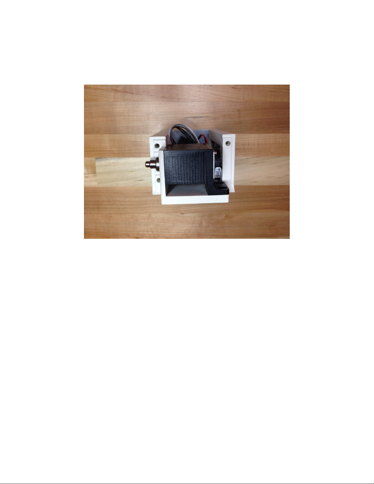
2. HARDWARE INSTALLATION
Align RFID Locking Device holes with your device’s threaded hole pattern and secure using M4 socket
head cap screws.
Fig. 6. RFID locking device hole pattern.
3. OPERATION
Place PNP Robotics RFID card with at least one available use onto RFID antenna. After reading the card,
the LCD screen shall display the remaining number of uses and unlocking time in minutes, and move the
locking pin to the unlocked position. Once remaining time has reached 20 minutes, the LCD screen shall
turn on and display the remaining time in minutes. Once the countdown timer has expired, the device
shall automatically move the locking pin to the locked position.
4. BATTERY REPLACEMENT
Upon detecting low battery power, the LCD screen shall display the message Low Battery. Please open
front panel by removing the two M2 screws. Disconnect 2-pin battery connector from electronics board,
and remove battery holder. Replace batteries with 4 AA Lithium polymer batteries, such as Energizer
L91, or equivalent product.
 Loading...