

Page 1

Process Level Technology, Ltd.
MAG-GAGE® IOM
INSTALLATION, OPERATION AND MAINTENANCE MANUAL
LEAR CREEK AVE LEAGUE CITY, TEXAS 77573
888 C
Phone # (281) 332-MAG1(6241)
Fax # (281) 332-0232
WWW.MAG-GAGE.COM
PLT MAG-GAGE Revision 06
Page 2

Process Level Technology, Ltd.
MAG-GAGE®
Process Level Technology, Ltd.
Installation, Operation and Maintenance Instructions
Contents
Section 2.1.0. Magnetic Level Gages
“MAG-GAGE®”
2.1.0. Description
2.1.1. Introduction
2.1.2. Components
2.1.3. Chamber Material
2.1.4. Internal Float
2.1.5. Float Submergence
2.1.6. Gage ratings
2.1.7. Hydrostatic Testing
2.2.0. Level Indication
2.2.1. Introduction
2.2.2. Single Indication (SI)
2.2.3. Single Indication - Reference Guide
2.2.4. Flag/Flipper Indication (FL)
2.2.5. Flag/Flipper Indication - Reference Guide
2.2.6. Flag /Flipper Indication - Retrofit
2.3.0. Installation
2.3.1. Inspection
2.3.2. Chamber Orientation
2.3.3. Connection Valves
2.3.4. Float Orientation
2.3.5. Chamber Gaskets
2.3.6. Flanges and Connections
2.3.7. Interface Applications
2.4.0. Operation
2.4.1. Introduction
2.4.2. Procedures/Storage
2.5.0. Removal From Service
2.5.1. Introduction
2.5.2. Procedures
OPS-001 Revision 6 Page 2 of 30 December 17, 2018
Page 3

Process Level Technology, Ltd.
MAG-GAGE®
Process Level Technology, Ltd.
Installation, Operation and Maintenance Instructions
Contents
Section 2.0.0. Magnetic Level Gages (cont.)
2.6.0. Maintenance
2.6.1. Introduction
2.6.2. Procedures
2.7.0. Troubleshooting
2.7.1. Introduction
2.7.2. Float & Indicator Detachment
2.7.3. Differential Level
2.7.4. Defective Indicator
2.7.5. Switch Malfunctioning
2.8.0. Parts List
2.8.1. Introduction
2.8.2. Chamber
2.8.3. Indicator & Scale Assembly
2.9.0. Warranty
2.9.1. Introduction
2.9.2. Conditions
2.9.3. Provisions
2.10.0. Terms and Condition of Sale
2.10.1. Introduction
2.10.2. Terms
2.10.3. Shipment
2.10.4. Restocking
2.10.5. Cancellation
OPS-001 Revision 6 Page 3 of 30 December 17, 2018
Page 4

Process Level Technology, Ltd.
MAG-GAGE®
Process Level Technology, Ltd.
Installation, Operation and Maintenance Instructions
Contents
Section 3.0.0. Pneumatic Level Control
3.1.0. Non Bleed, Block & Bleed Switches – MGS-100
3.1.1. Introduction
3.1.2. Operating Specifications
3.1.3. Installation Procedures
3.1.4. Operation & Maintenance
3.2.0. Pneumatic Level Controller - LCP
3.2.1. Introduction
3.3.2. Operation
Section 4.0.0. Electronic Level Control
4.1.0. Electric Switches – MGS200EX (/2)
4.1.1. Introduction
4.1.2. Specifications
4.1.3. Mounting
4.1.4. Operation
4.1.5. Electrical Wiring - Rising Level
4.1.6. Electrical Wiring - Falling Level
4.2.0. Electric Switches - MGS500EX (/2)
4.2.1. Introduction
4.2.2. Specifications
4.2.3. Mounting
4.2.4. Operation
4.2.5. Electrical Wiring-Raising Level
4.2.6. Electrical wiring-Falling Level
OPS-001 Revision 6 Page 4 of 30 December 17, 2018
Page 5

Process Level Technology, Ltd.
MAG-GAGE®
4.3.0. Electric Switches – MGS700EX(/2) MGS-900EX(/2)
4.3.1. Introduction
4.3.2. Specification
4.3.3. Mounting
4.3.4. Operation
4.3.5. Electrical Wiring-Rising Level
4.3.6. Electrical Wiring-Falling Level
OPS-001 Revision 6 Page 5 of 30 December 17, 2018
Page 6

Process Level Technology, Ltd.
MAG-GAGE®
Magnetic Level Gages
Installation, Operation and Maintenance Instructions
Section 2.1.0. - Description
2.1.1. INTRODUCTION
Process Level Technology, Ltd magnetic level gages (MAG-GAGE®) are an indirect reading liquid level
indicator. The magnetic level gage series utilize non-magnetic 2.00-inch, schedule 40 chambers (standard)
manufactured to length specifications with process connections that match those of the vessel or tank. For some
high pressure, low gravity applications, a 3.00-inch schedule 40 chamber is available. The process connections
may be:
1. Side mounted, threaded, flanged or socket welded
2. Top and bottom flanged mounted
3. Tank top mounted
4. Combination
A variety of mounting styles is available to suit any vessel or piping requirements. Refer to the drawing depicting
magnetic level gage mounting configurations.
2.1.2. COMPONENTS
The gage chamber contains a magnetic float and is completely isolated from the indicator housing attached to the
outside of the gage chamber. External indicators consist of a single yellow or continuous flag/flipper models. The
magnetic float maintains a magnetic bond with the external level indicator. As the level of the process medium
fluctuates within the tank and gage chamber, the float reacts accordingly with the indicator recording the level of
the fluid within the chamber.
2.1.3. CHAMBER MATERIAL
Gages are manufactured to meet exact specifications of the process media such as operating pressure, temperature,
specific gravity, etc. Standard chamber materials are 316/304 stainless steel however any non-magnetic material
may be used. Other chamber materials that are available include CPVC, Kynar, Hastelloy, Alloy 20, Zirconium,
Monel, Etc.
OPS-001 Revision 6 Page 6 of 30 December 17, 2018
Page 7

Process Level Technology, Ltd.
MAG-GAGE®
.
Magnetic Level Gages
Installation, Operation and Maintenance Instructions
Section 2.1.0. – Description
2.1.4. INTERNAL FLOAT
A magnetized float is contained inside the float chamber and is designed to the requirements of the process
conditions. For this reason floats are not interchangeable unless the process conditions and gage chambers are
identical. The float moves freely inside the chamber reacting to fluctuating level changes within the adjoining
vessel.
2.1.5. FLOAT SUBMERGENCE
Under normal operating conditions, the float should be submerged about 80% or more in the process fluid. It is
important to note, however, that the position of the float in the media will vary with different process conditions.
Float magnets are located in the upper portion of the float.
2.1.6. GAGE RATINGS
Magnetic level gages can be designed for operating conditions from full vacuum service up to 5000 PSIG, 1100
degrees F, and a minimum gravities of 0.20. All magnetic gages with alloy chambers will have full ANSI ratings
based on flange classifications. Gages with CPVC, Kynar (PVDF) or Fiberglass shields will have 150 PSIG
ratings only.
2.1.7. HYDROSTATIC TESTING
Gage chambers are hydrostatically tested to 150% of indicated gage rating without floats installed. Floats are
tested individually. Gages can be field hydrostatically tested after installation at the operator's discretion.
CAUTION: Do not conduct hydrostatic testing of the magnetic gage chamber attached to a
process vessel with the float installed. If a gage is field tested with the float installed, the float
may crush and chamber may become damaged. This procedure will void the warranty.
OPS-001 Revision 6 Page 7 of 30 December 17, 2018
Page 8

Process Level Technology, Ltd.
MAG-GAGE®
Magnetic Level Gages
Installation, Operation and Maintenance Instructions
Section 2.2.0. - Level Indication
2.2.1. INTRODUCTION
There are two types of external level indication options offered by Process Level Technology, Ltd. for magnetic
level gages. The single indicator (ST)/(SST) is recommended for stagnant storage level applications with little or
no level fluctuations. The wide flag indicator (WF)(SWF) is recommended for turbulent or high vibration level
conditions.
2.2.2. SINGLE TRACKER INDICATION (ST or SST)
The single follower assembly used for indicating level consists of a rectangular yellow magnetic follower sealed
in a channel with a 316 stainless steel calibration scale marked in feet and inches, total inches or in centimeters.
The indicator is mounted parallel and immediately adjacent to the gage chamber to allow maximum magnetic
coupling between the float and the follower within the indicator channel. The indicator is sealed to prevent dirt
and moisture accumulation. A red bumper is positioned at the bottom of the channel to cushion the impact of the
follower against the cover. Although the yellow follower provides maximum visibility even at nighttime, retrofit
kits for illuminating gages are available.
2.2.3. SINGLE TRACKER INDICATION - REFERENCE GUIDE
A black reference guide in the center of the yellow follower allows the operator to match the graduated scale with
the level of the process fluid. A nameplate at the lower end of the scale provides zero level indication. If the
yellow follower is decoupled from the internal float's magnetic field, the follower will descend below the zero
point on the scale. Thus, when the vessel is empty, the level gage will read zero and the yellow follower will
remain visible. To prevent the float from losing magnetic coupling with the follower, a spring is mounted inside
the top and bottom of the gage chamber. This cushion the impact of the float against the chamber ends when the
vessel is completely full or empty. The float and the follower are magnetically coupled when the follower remains
visible. If the magnetic coupling is lost between the float and follower, use a hand magnet to attract the follower
until it is contained within the float's magnetic field. Refer to the Troubleshooting portion of the manual, Section,
2.7.2.
OPS-001 Revision 6 Page 8 of 30 December 17, 2018
Page 9

Process Level Technology, Ltd.
MAG-GAGE®
Magnetic Level Gages
Installation, Operation and Maintenance Instructions
Section 2.2.0. - Level Indication (cont.)
2.2.4. WIDE FLAG/FLIPPER INDICTION (WF),(SWF)
Process Level Technology offers a continuous Wide Flag or Flipper style indicator as an option to the Single
Yellow Follower indicator. Flag indications are industrial grade level indicators which consist of a series of
ceramic flags, black on one side, yellow on the other. As the magnetic float reacts to level fluctuations, each flag
or flipper will rotate 180 degrees to reveal the opposite color.
Process Level Technology, Ltd. a flipper is housed in a rugged sealed housing with a recessed glass window and
rotates on a ceramic and stainless steel surface. This eliminates the flippers from sticking or hanging up. The
unique design prevents all flippers from rotating in excess of 180 degrees and each flag is magnetically locked to
the next. Wide Flag indicators are recommended where surging or turbulent level conditions exist. Each flag
indicator is 1.40 inches wide and is more visible than the standard single indicator. These are available with or
without scales up to 20 ft.
2.2.5. WIDE FLAG/FLIPPER INDICATION - REFERENCE GUIDE
Yellow represents liquid column, Black represents vapor space.
2.2.6. WIDE FLAG/FLIPPER INDICATION - RETROFIT
When flipper style indicators are purchased with a Process Level Technology, Ltd. magnetic level gage, no
installation is necessary. If the indicator is removed or a retrofit kit is purchased for a gage already in service,
however, the following steps should be noted:
1. The mounting clamps connecting the flipper assembly to the gage chamber are adjustable to most
manufacturers' standard, (i.e. 1.50 inch to 2.50-inch pipe). If the gage is in service and there is liquid in the
tank, only the flippers adjacent to the float will rotate to yellow when the indicator assembly is clamped on.
2. Run a magnet along the window of the indicator from zero to where yellow is showing as noted, or
3. Drain the gage to zero on the indicator, and then fill again. As the float rises, the level indicator will react
accordingly and will be reset properly.
OPS-001 Revision 6 Page 9 of 30 December 17, 2018
Page 10

Process Level Technology, Ltd.
MAG-GAGE®
Magnetic Level Gages
Installation, Operation and Maintenance Instructions
Section 2.3.0. - Installation
2.3.1. INSPECTION
All magnetic level indicators are securely packed in crates to provide maximum protection of the equipment
during shipment. It is important to unpack and inspect each gage upon receipt to insure the indicator and chamber
were not damaged in shipment. If you should find damaged parts, contact Process Level Technology, Ltd.
immediately. All Process Level Technology, Ltd. magnetic gages are fully insured against damage or loss unless
specified by the customer otherwise. Claims must be filed within 15 days from the date of receipt of shipment.
2.3.2. CHAMBER ORIENTATION
The magnetic float is packaged separately for shipment; the Float is strapped externally to the outside of
chamber which should be removed before installation. The float chamber should always be leveled vertically. If
it is not leveled correctly, the float may be magnetically uncoupled from the level indicator during operations.
2.3.3. CONNECTION VALVES
Valves should be installed between the process vessel and level gage to allow for isolation, draining, and cleaning
purposes. (See section 2.6.2. on Maintenance for more details on cleaning and maintenance procedures). Standard
block valves can be ordered with the gage or separately from Process Level Technology. Ball check valves are
not necessary for magnetic level gages. If certain valve specifications are required, please advise Process Level
Technology, Ltd. accordingly.
2.3.4. FLOAT ORIENTATION
The internal magnetic float has a preferred orientation vertically which is inscribed at the top of the float. Install
the float properly by taking note of the correct orientation through the chamber flange connection. If the float is
installed into the chamber inverted, it will not couple with the external indicator correctly, resulting in improper
level indication. Floats that are installed in gages with inverted chamber construction will contain a loop at the
top of the float for installation and removal purposes. Internal floats should be installed after any hydrostatic
field tests of the chamber and connecting vessel are complete.
OPS-001 Revision 6 Page 10 of 30 December 17, 2018
Page 11

Process Level Technology, Ltd.
MAG-GAGE®
Magnetic Level Gages
Installation, Operation and Maintenance Instructions
Section 2.3.0. - Installation (cont.)
2.3.5. CHAMBER GASKETS
Standard magnetic level gages are supplied with 0.125-inch composition gaskets. If this type of gasket is not
compatible with the process media, appropriate gaskets should be used in replacement of those shipped with the
gage.
2.3.6. FLANGES AND CONNECTIONS
Process connections and vent/drain flanges are designed to meet each customer's specifications. All flange
boltholes straddle the centerline unless otherwise specified. Both male and female threaded connections and
socket weld connections are available. DO NOT WELD ON MAG-GAGE OR ON THE VESSEL WITH
INDICATOR AND FLOAT INSTALLED, THIS WILL DESTROY THE MAGETIC CIRCUIT.
2.3.7. INTERFACE APPLICATIONS
Magnetic level gages can be used to identify fluid interfaces only if the proper specific gravities have been
identified at the maximum operating conditions. The float can designed to float in one media while sinking in the
other. Immiscible oil over water levels is an example. Care should exercised, however, when using magnetic
level gages in interface applications because rag layers may exist which are difficult to identify.
Do not install a gage with two floats and two single indicators on one chamber for an interface. In this case the
two floats may collide causing incorrect readings. Chambers can be manufactured with multiple connections for
maximum process influx. The proper method is to install one gage per process phase, not a combination.
OPS-001 Revision 6 Page 11 of 30 December 17, 2018
Page 12

Process Level Technology, Ltd.
MAG-GAGE®
Magnetic Level Gages
Installation, Operation and Maintenance Instructions
Section 2.4.0. - Operation
2.4.1. INTRODUCTION
It is important that all instructions pertaining to entering magnetic level gages into service be read thoroughly first
before commencing with service operations. Failure to do so may void the warranty by subjecting the gage to a
potential safety hazard.
2.4.2. PROCEDURES
1. Check that the operating conditions, (temperature, pressure and specific gravity) are within that maximum
rating of the gage. Each gage has a permanent nameplate indicating process specifications, serial number,
tag number, etc. It is critically important to check that the specific gravity of the process media is specified
at the maximum operating conditions.
2. The gage chamber should be leveled vertically, empty, blocked in and isolated. Check to see that all drain
and vent plugs are in place. Close all vent and drain valves if plugs are not used.
3. For standard gages, install the float by removing the bottom drain flange located at the base of the gage.
The float is marked TOP to insure proper orientation. A spring is attached to the inside of the drain flange
to cushion the float when the vessel is empty. Reinstall the bottom drain blind flange with a new flange
gasket after the float is in place.
4. For inverted gages, remove the top vent blind flange from the gage chamber. Install the float by inserting
a string through the float loop and lower the float into position slowly. Remove the string from the float
and chamber after the float is resting on the bottom of the gage. An auxiliary magnet may be required to
recouple the indicator, (either single follower or flipper indicator), to the internal float.
5. Reinstall the blind flange with a new gasket. The gage chamber should be isolated with no opening to
atmosphere. Check to see that all drain and vent plugs are securely in place and that any vent and drain
connections are closed.
OPS-001 Revision 6 Page 12 of 30 December 17, 2018
Page 13

Process Level Technology, Ltd.
MAG-GAGE®
Magnetic Level Gages
Installation, Operation and Maintenance Instructions
Section 2.4.0. - Operation
2.4.2. PROCEDURES (cont.)
6. When the gage is mounted and ready for placement into service, PARTIALLY OPEN THE TOP
PROCESS CONNECTION VALVE FIRST and very slowly to allow initial pressure and temperature
equalization between the vessel and the level gage. This allows the process conditions of the vessel to
equalize with the gage slowly and reach operating conditions at a slow, even, and reasonable rate.
7. CAUTION. DO NOT OPEN THE BOTTOM PROCESS CONNECTION VALVE FIRST. IF THE
BOTTOM VALVE IS OPENED FIRST WITH THE TOP VALVE CLOSED AND THE VESSEL IS
UNDER PRESSURE, THE INTERNAL FLOAT WILL RISE INSTANTLY AND LODGE ITSELF
INTO THE TOP OF THE CHAMBER CAUSING SEVERE DAMAGE TO THE FLOAT AND
CHAMBER.
8. After the float chamber has reached process conditions, continue to open the TOP process connection
valve slowly, allowing any liquid or condensate to enter the gage slowly. This procedure is critically
important for high pressure and temperature applications. The float and indicator may react or rise to
condensate accumulation migrating through the top valve with the bottom valve closed.
9. When the gage chamber has attained normal operating conditions, open the BOTTOM process valve
connection slowly. This will allow proper fluid entry into the gage chamber under normal operating
conditions. The level indicator should rise vertically, thus rendering a fluid level. Flag or flipper indication
will result in black to yellow rotation of the flippers as the fluid rises. At this point, installation should be
complete. Allow at least 30 minutes for both top and bottom valve procedures.
10. Please note, under elevated operating conditions, the indicator may record a significant level from
condensate influx through the top valve before the bottom valve is opened. If this is the condition, it is
possible the indicator (and float) may readjust and fall slightly from the effects of final process
equalization after the bottom valve is completely opened.
11. Extended Storage: All MAG-GAGE® magnetic level gages and gage accessories not put in service shall
be stored inside in the original creates
OPS-001 Revision 6 Page 13 of 30 December 17, 2018
Page 14

Process Level Technology, Ltd.
MAG-GAGE®
Magnetic Level Gages
Installation, Operation and Maintenance Instructions
Section 2.5.0. - Removal from Service
2.5.1. INTRODUCTION
To remove the gage from service, the next steps should be followed to prevent danger to personnel and damage
to the gage when the vessel is pressurized.
2.5.2. PROCEDURES
1. Close the bottom process connection valve first to prevent further process influx to the gage.
2. Completely close the top process connection valve to isolate the gage from the process conditions.
3. Attach proper vapor collection equipment to the gage vent connection if required.
4. Open the vent valve slowly to relieve gage pressure and allow ambient air influx.
5. Attach the proper liquid collection equipment to the drain connection is required.
6. Open the drain valve slowly to remove remaining gage liquid.
7. CAUTION: Never use the vent or drain on a gage as a pressure relief mechanism for the process system.
Doing so may permanently damage parts of the gage as well as inducing a safety hazard.
8. DO NOT remove float from chamber before ambient temperature is obtained. Once ambient
temperature is obtained, wait an ADDITIONAL TWO HOURS before removing float from chamber
for safety purposes.
OPS-001 Revision 6 Page 14 of 30 December 17, 2018
Page 15

Process Level Technology, Ltd.
MAG-GAGE®
Magnetic Level Gages
Installation, Operation and Maintenance Instructions
Section 2.6.0. - Maintenance
2.6.1. INTRODUCTION
Process Level Technology, Ltd. magnetic level gages contain a standard 0.50 inch vent and drain plug in the top
and bottom of the gage chamber to allow cleaning and removal of the process fluid if required. Socket weld vent
and drain valve connections are available. Some gages are connected to a solvent or steam line that allows empty
gages without floats to be decontaminated or blown down periodically without removing the gage from the vessel
location. Process Level Technology, Ltd. magnetic gages should be maintained and inspected on at least an annual
basis, or more frequently depending on the process system.
2.6.2. PROCEDURES
1. Block in the gage chamber with the process connection valves or wait until the vessel is empty and out of
service.
2. Close the bottom valve first and the top valve second.
3. Open the vent valve slowly or remove vent plug carefully to depressurize the gage especially if the gage has
been under pressure.
4. Open the drain valve slowly or remove the drain plug carefully to allow any remaining fluid to drain from the
chamber.
5. When all of the gage fluid has been drained, carefully remove the drain flange and float from the gage
chamber. Be sure to examine the float for excessive wear and clean as required.
6. Clean the inside wall of the chamber with a "bottle brush" or similar scrubbing tool. Some processes may
dictate the use of a suitable solvent for cleaning.
7. After cleaning of the chamber, replace the float and drain flange. A new flange gasket should be installed.
Use gaskets compatible with the process media if replaced.
OPS-001 Revision 6 Page 15 of 30 December 17, 2018
Page 16

Process Level Technology, Ltd.
MAG-GAGE®
Magnetic Level Gages
Installation, Operation and Maintenance Instructions
Section 2.6.0. - Maintenance
2.6.2. PROCEDURES (cont.)
8. Check the stainless steel pipe clamps to insure they are tight and adjust the scale channel. Correctly match the
zero point to process connection elevations.
9. If necessary, use a permanent magnet to attract the yellow indicator until it is coupled to the float inside the
chamber.
OPS-001 Revision 6 Page 16 of 30 December 17, 2018
Page 17

Process Level Technology, Ltd.
MAG-GAGE®
Magnetic Level Gages
Installation, Operation and Maintenance Instructions
Section 2.7.0. - Troubleshooting
2.7.1. INTRODUCTION
Process Level Technology, Ltd. magnetic level gages are simple to install and operate. The following
troubleshooting tips may be of assistance during installation and startup. Complete reading of this is required.
2.7.2. FLOAT & INDICATOR DETACHMENT
1. If detachment is a frequent problem, it could be caused by several factors, most of them resulting from
improper installation of the gage, particularly the float.
2. Check to ensure that the scale and channel assembly is fastened tight against the gage chamber so that
magnetic coupling is maintained from top to bottom of the indicator.
3. Check to ensure the internal magnetic float within the chamber is right side up. If the float was installed
inverted, the single yellow indicator will magnetically couple, but the actual process level will be higher that
what the indicator records. All floats are clearly marked TOP. Floats designed for inverted gages will have a
loop welded at the top of the float for installation and removal purposes.
4. If the float springs mounted in the top and bottom of the gage chamber have been removed, the float could
rise past the top of the indicator and lose magnetic coupling with the indicator.
5. If the process connection dimension has been miscalculated and the gage length is too long, do not attempt
installation because it will warp the chamber. A warped chamber will prohibit the float to move freely. This
can cause float and indicator detachment.
2.7.3. DIFFERENTIAL LEVEL
This can occur during startup and is easily corrected. Under normal operating conditions, most floats are about
80% submerged in the process media. It is important to note that the position of the float in the fluid will vary
with different process conditions. To attain a true level elevation, adjust the scale vertically to get an exact reading.
Magnetic Level Gages
OPS-001 Revision 6 Page 17 of 30 December 17, 2018
Page 18

Process Level Technology, Ltd.
MAG-GAGE®
Installation, Operation and Maintenance Instructions
Section 2.7.0. - Troubleshooting (cont.)
2.7.4. DEFECTIVE INDICATOR
If the glass indicator cover is cracked or broken, a replacement cover can be shipped within 24 hours after receipt
of order. One advantage of the magnetic level gage is the indicator assembly can be serviced without removing
the gage chamber from service. To replace the indicator cover, remove the four screws from cover plate at the top
and bottom of the indicator channel. There are two red gaskets beneath each cover that require removal. Remove
the two red seal strips and slide the glass plate cover out of the channel. Clean any debris or fragments. Replace
the glass cover with the new glass plate by sliding into the channel again. Replace each red side and top gaskets
with the top and bottom covers. If the gage is inexcess of 6 feet in length, it may be easier to remove the indicator
from the channel.
2.7.5. SWITCH MALFUNCTIONING
All level switches may be wired to trip on rising or falling level. After the switch is connected to the desired alarm
function, it is necessary to set the switch. This is accomplished by passing the float either manually or by filling
the gage chamber until it passes the highest switch. This will trip the switch to the desired setting so it will alarm
properly with rising or falling level.
Magnetic Level Gages
OPS-001 Revision 6 Page 18 of 30 December 17, 2018
Page 19

Process Level Technology, Ltd.
MAG-GAGE®
Installation, Operation and Maintenance Instructions
Section 2.8.0. - Parts List
2.8.1. INTRODUCTION
When ordering spare parts for the MAG-GAGE® series magnetic level gage, the following information will be
required.
1. Serial number of the gage or accessory item.
2. Description of parts to be ordered.
3. Model number of the parts to be ordered, if known.
4. Original purchase order, if known.
9
2.8.2. CHAMBER
1. Vent plug.
2. Float chamber
3. Chamber blind flange, spring, and gasket.
4. Drain plug.
5. Internal magnetic float.
2.8.3. INDICATOR & SCALE ASSEMBLY
1. Channel assembly
2. Anodized Alum. Indicator track with single tracker follower or wide flag indication
3. Stainless Steel Indicator track with single tracker follower or wide flag indication
4. Top and bottom seals
5. Calibration scale (total inches, feet & inches, centimeters)
6. Chamber clamps
7. Identification Tag.
Magnetic Level Gages
OPS-001 Revision 6 Page 19 of 30 December 17, 2018
Page 20

Process Level Technology, Ltd.
MAG-GAGE®
Installation, Operation and Maintenance Instructions
Section 2.9.0. - Warranty
2.9.1. INTRODUCTION
All Process Level Technology, Ltd. products are warranted against defects in material and workmanship for five
years from the date of shipment. Process Level Technology, Ltd. will repair or replace those products that fail to
perform as specified with the following exceptions. This warranty does not apply to glass breakage or any other
liability other than materials and workmanship.
2.9.2. CONDITIONS
1. Products repaired or modified by persons that are unauthorized by Process Level Technology, Ltd
2. Products subject to misuse, negligence or accidents
3. Products that are connected installed or otherwise used in such a way not in accordance with the
manufacturer's instructions.
PLT will repair or replace, at PLT’s election, defective items which are returned to PLT by the original
purchaser within the period specified above from the shipment date of the item and which is found, upon
examination by PLT, to its satisfaction contain defects in materials or worksmanship which arose only under
normal use and service and which are not the result of either alterations, misuse, abuse, improper or inadequate
adjustments, applications or servicing of the product. PLT’s warranty does not include onsite repairs or services.
Field service rates can be supplied upon request.
If the product is believed to be defective, the original purchaser shall notify PLT and request a Return Material
Authorization Form before returning the material to PLT, with transportation prepaid by the purchaser. The
product, with repaired or replaced parts, shall be returned to the purchaser at any point in the world with
transportation prepaid by PLT for best-way transportation only. PLT is not responsible for expedited shipping
charges.
If inspection by PLT does not disclose any defects in material or workmanship, PLT will supply the purchaser
with a detailed quote for repairs. Repairs will not be done until a purchase order is issued by the purchaser for
any items not covered under warranty.
The materials of construction for all PLT products are clearly specified and it’s the sole responsibility of the
purchaser to determine the compatibility of the material for the application.
2.9.3. PROVISIONS
This warranty is in lieu of any other warranty expressed or implied by any party other than Process Level
Technology, Ltd. Repairs and/or replacements shall be at the sole discretion of Process Level Technology, Ltd.
based on the terms and conditions.
Magnetic Level Gages
OPS-001 Revision 6 Page 20 of 30 December 17, 2018
Page 21

Process Level Technology, Ltd.
MAG-GAGE®
Installation, Operation and Maintenance Instructions
Section 2.10.0. - Terms and Condition of Sale
2.10.1. INTRODUCTION
All orders should be entered to the following address:
Process Level Technology, Ltd.
888 Clear Creek Ave.
League City, Texas 77573
PH# (281) 332-MAG1(6241), Fax# (281) 332-0232
2.10.2. TERMS
The payment terms are Net 30 days to approved customers. Sales representatives may assume collection
responsibility for new accounts at their discretion. Late charges will be added at the rate of 1.50% per month.
2.10.3. SHIPMENT
All shipments will be F.O.B. factory location, Houston, Texas, via motorfreight insured. Freight charges are
normally prepaid and added to invoice unless specified otherwise.
2.10.4. RESTOCKING
Every magnetic level gage is designed and manufactured to exact customer specifications. As a result, there will
be no restocking option after shipment is made.
2.10.5. CANCELLATION
Cancellation charges after order placement will be at the discretion of Process Level Technology, Ltd. and
dependent upon production phase of the product.
Pneumatic Level Control
OPS-001 Revision 6 Page 21 of 30 December 17, 2018
Page 22

Process Level Technology, Ltd.
MAG-GAGE®
Installation, Operation and Maintenance Instructions
Section 3.1.0. - Non Bleed, Block & Bleed Switches (MGS-100)
3.1.1. INTRODUCTION
MGS-100 pneumatic switches are designed for use on magnetic MAG-GAGE® series gages only. The MGS-100
is a non-bleed, block and bleed pneumatic switch operates when the magnetic field of a Process Level
Technology, Ltd. magnetic float passes by it, either on a rising or falling level condition. Since there is no physical
interaction or connection between the switch and float, it is very important that all installation instructions be
followed properly for the switch to function reliably. Please read all installation and operation instructions before
beginning installation.
3.1.2. OPERATING SPECIFICATIONS
Medium: Filtered Air or Gas
Supply Pressure: VAC to 200 PSIG
Max. Temp: 200 degrees F (93C)
Air Flow: 29 SCFM @ 100 PSIG
Air Consumption: Zero SCFM
3.1.3. INSTALLATION
1. Loosen the included hose clamps completely and install them so they surround the gage chamber.
Reattach the clamp to itself, make 2 or 3 turns of the clamp's screw but do not reattach completely.
2. Insert the top "L" shaped bracket under the top hose clamp and tighten the clamp to the gage chamber.
The top bracket is the bracket above the front label if the writing is right side up. Before tightening, you
may adjust the height at which you would like the alarm to trigger. The trigger point is at the midpoint of
the enclosure.
3. Since the switch should be securely fastened to the gage chamber by the top clamp, slide the bottom
hose clamp over the bottom bracket and tighten the clamp to the gage chamber.
Pneumatic Level Control
OPS-001 Revision 6 Page 22 of 30 December 17, 2018
Page 23

Process Level Technology, Ltd.
MAG-GAGE®
Installation, Operation and Maintenance Instructions
Section 3.1.0. - Non Bleed, Block & Bleed Switches MGS-100
3.1.4. INSTALLATION - (cont.)
4. The alarm switch should be mounted so that it is level with the ground. If it is not level, loosen the hose
clamps, adjust the switch's alignment, and when the switch is level, retighten the hose clamps. Improper
alignment may cause the switch to malfunction.
5. The switch must also be flush and tighten against the chamber. Failure to do this results in vibration and
rattling of the switch, which may in extreme circumstances cause the switch to fail.
6. No material should be present between the switch housing and the gage chamber. Any material present
can interfere with the magnetic field of the internal float and prevent proper activation of the switch.
3.1.6. OPERATION & MAINTENANCE
1. The pneumatic supply line must be connected to the connection labeled 1 OR 2 The output to the alarm
or other signaling device must be connected to the connection labeled PORT 3.
2. PORT 1 is the supply port that will activate the output when the float passes above the switch. Port 2 is
the vent It is to be used as a HIGH LEVEL indicator.
3. PORT 2 activates the output when the float passes below the switch. Port 1 is the vent IT is to be used as
a LOW LEVEL indicator.
4. All input and output connections are 1/4-inch NPT connections.
5. The muffler must remain uncovered and clean for proper non-bleeding functioning of the switch. If
covered, the interior of the switch may pressurize and explode.
6. Pneumatic connections must provide air or gas that is free of particulate matter or debris. Dirty supply gas
may cause the valve inside to clog and lead the switch to failure.
7. When the switch is first installed, it is necessary to set the switch for normal operation. This is accomplished by
passing the float pass the switch, the chamber can be filled with liquid so the float will pass the highest switch and
then drained, or by manually sliding the switch pass the float in both directions. If the switch is being positioned
above the float, the float must pass in the down direction before installation and conversely if the switch is positioned
below the float.
Pneumatic Level Control
OPS-001 Revision 6 Page 23 of 30 December 17, 2018
Page 24

Process Level Technology, Ltd.
MAG-GAGE®
Installation, Operation and Maintenance Instructions
Section 3.2.0. - Pneumatic Level Controller (LCP)
3.2.1. INTRODUCTION
The LCP Pneumatic Level Switch Controller provides supply and vent air control for two pneumatic switches
used in a high and low point level application. The LCP is designed to be used with pneumatic switches on
magnetic MAG-GAGE® series gages only.
3.2.2. OPERATION
1. As the float rises past the high pneumatic switch level, it will supply air to the port P4 of the controller.
2. When port P4 has air supplied to it there will be a pneumatic signal out of port 2 of the controller. The
pneumatic signal will continue until the float passes the low pneumatic switch.
3. The low switch will supply a signal to port P2 on the controller therefore shutting the pneumatic signal
off. The output signal will stay off until the float rises past the high pneumatic switch.
4. The cycle will then repeat.
5. To reverse the output on the controller, connect the high pneumatic switch to port P2, and the low
pneumatic switch to P4 on the controller.
Electronic Level Control
OPS-001 Revision 6 Page 24 of 30 December 17, 2018
Page 25

Process Level Technology, Ltd.
MAG-GAGE®
Installation, Operation and Maintenance Instructions
Section 4.1.0. – Electric Level Switches (MGS-200EX/MGS-200EX2)
4.1.1 INTRODUCTION
The MGS-200EX and MGS-200EX2 are hermetically sealed bistable-latching switches designed for magnetic
MAG-GAGE® series gages only. The MGS-200EX has single pole double throw contacts (SPDT) and the MGS200EX2 has double pole, double throw contacts (DPDT). The switch will change state when the float passes by
it in a rising or falling level condition. The switch remains in a latched position until the float passes the switch
in the opposite direction. The MGS-200EX and MGS-200EX2 does not require any routine maintenance
4.1.2 SPECIFICATIONS
Maximum switching voltage: 150 VDC/VAC
Maximum switching current amps: 1.0 amps (VDC/VAC)
Maximum switching wattage: 25 watts (VDC/VAC)
Minimum breakdown volts: 250 VDC
Maximum Temperature (standard): 350 degrees F
Maximum Temperature (HT option): 800 degrees F
Ambient Temperature Range -25C to +85C
Dead Band: 0.35 inch
Electrical Area Classification: Class I Div I Grp. B,C,D
4.1.3 MOUNTING
The MGS-200EX/EX2 is mounted to the MAG-GAGE® chamber with all 316 Stainless Steel worm gear pipe
clamps. Rod mounted switch assemblies are available as a factory installed option. Switch points can be changed
at any time by loosening the clamps and sliding the switch vertically to the desired set point.
4.1.4 OPERATION
When the switch is first installed, it is necessary to set the switch for normal operation. This is accomplished by
passing the float pass the switch, the chamber can be filled with liquid so the float will pass the highest switch
and then drained, or by manually sliding the switch pass the float in both directions. If the switch is being
positioned above the float, the float must pass in the down direction before installation and conversely if the
switch is positioned below the float.
Electronic Level Control
Installation, Operation and Maintenance Instructions
OPS-001 Revision 6 Page 25 of 30 December 17, 2018
Page 26
Process Level Technology, Ltd.
MAG-GAGE®
Section 4.3.0. – Electric Level Switches (MGS-200EX/MGS-200EX2)
Caution: If there is a need to take the switch out of service or disconnect it for any reason, then make the sure
the circuit is de-energized.
Note: Keep cover tightly closed when in operation. To prevent ignition of GRP. B atmospheres a approved
sealing fitting must be installed
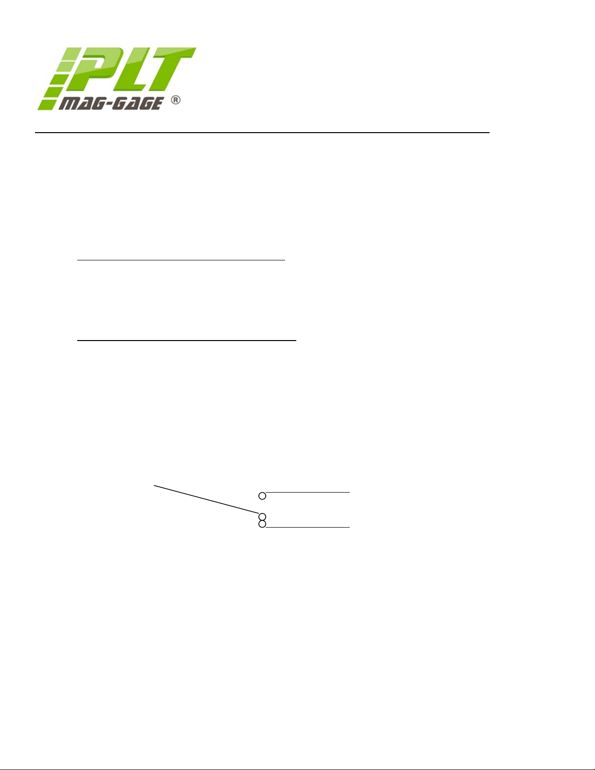
4.1.5 ELECTRICAL WIRING – RISING LEVEL
N/O Red Terminal 1 Closes on rising level.
C Green Terminal N
N/C Blue Terminal 2 Opens on rising level.
4.1.6 ELECTRICAL WIRING – FALLING LEVEL
N/C Red Terminal 1 Opens on falling level.
C Green Terminal N
N/O Blue Terminal 2 Closes on falling level.
(N) Green
(1) Red
(2) Blue
Electronic Level Control
Installation, Operation and Maintenance Instructions
OPS-001 Revision 6 Page 26 of 30 December 17, 2018
Page 27

Process Level Technology, Ltd.
MAG-GAGE®
Section 4.2.0. – Electric Level Switches (MGS-500EX/MGS-500EX2)
4.2.1 INTRODUCTION
The MGS-500EX and MGS-500EX2 are hermetically sealed bistable-latching switches designed for magnetic
MAG-GAGE® series gages only. The MGS-500EX has single pole double throw contacts (SPDT) and the MGS500EX2 has double pole, double throw contacts (DPDT). The switch will change state when the float passes by
it in a rising or falling level condition. The switch remains in a latched position until the float passes the switch
in the opposite direction.
The MGS-500EX and MGS-500EX2 does not require any routine maintenance
4.2.2 SPECIFICATIONS
Maximum switching voltage: 300 VDC/VAC
Maximum switching current amps: 3.0 amps (VDC/VAC)
Maximum switching wattage: 100 watts (VDC/VAC)
Minimum breakdown volts: 1000 VDC
Maximum Temperature (standard): 350 degrees F
Maximum Temperature (HT option): 650 degrees F
Ambient Temperature Range -25C to +85C
Dead Band: 0.35 inch
Electrical Area Classification: Class I Div I Grp. B,C,D
4.2.3 MOUNTING
The MGS-500EX/EX2 is mounted to the MAG-GAGE® chamber with all 316 Stainless Steel worm gear pipe
clamps. Rod mounted switch assemblies are available as a factory installed option. Switch points can be changed
at any time by loosening the clamps and sliding the switch vertically to the desired set point.
4.2.4 OPERATION
When the switch is first installed, it is necessary to set the switch for normal operation. This is accomplished by
passing the float pass the switch, the chamber can be filled with liquid so the float will pass the highest switch
and then drained, or by manually sliding the switch pass the float in both directions. If the switch is being
positioned above the float, the float must pass in the down direction before installation and conversely if the
switch is positioned below the float.
Electronic Level Control
Installation, Operation and Maintenance Instructions
OPS-001 Revision 6 Page 27 of 30 December 17, 2018
Page 28
Process Level Technology, Ltd.
MAG-GAGE®
Section 4.2.0. – Electric Level Switches (MGS-500EX/MGS-500EX2)
Caution: If there is a need to take the switch out of service or disconnect it for any reason, then make the sure
the circuit is de-energized.
Note: Keep cover tightly closed when in operation. To prevent ignition of GRP. B atmospheres a approved
sealing fitting must be installed
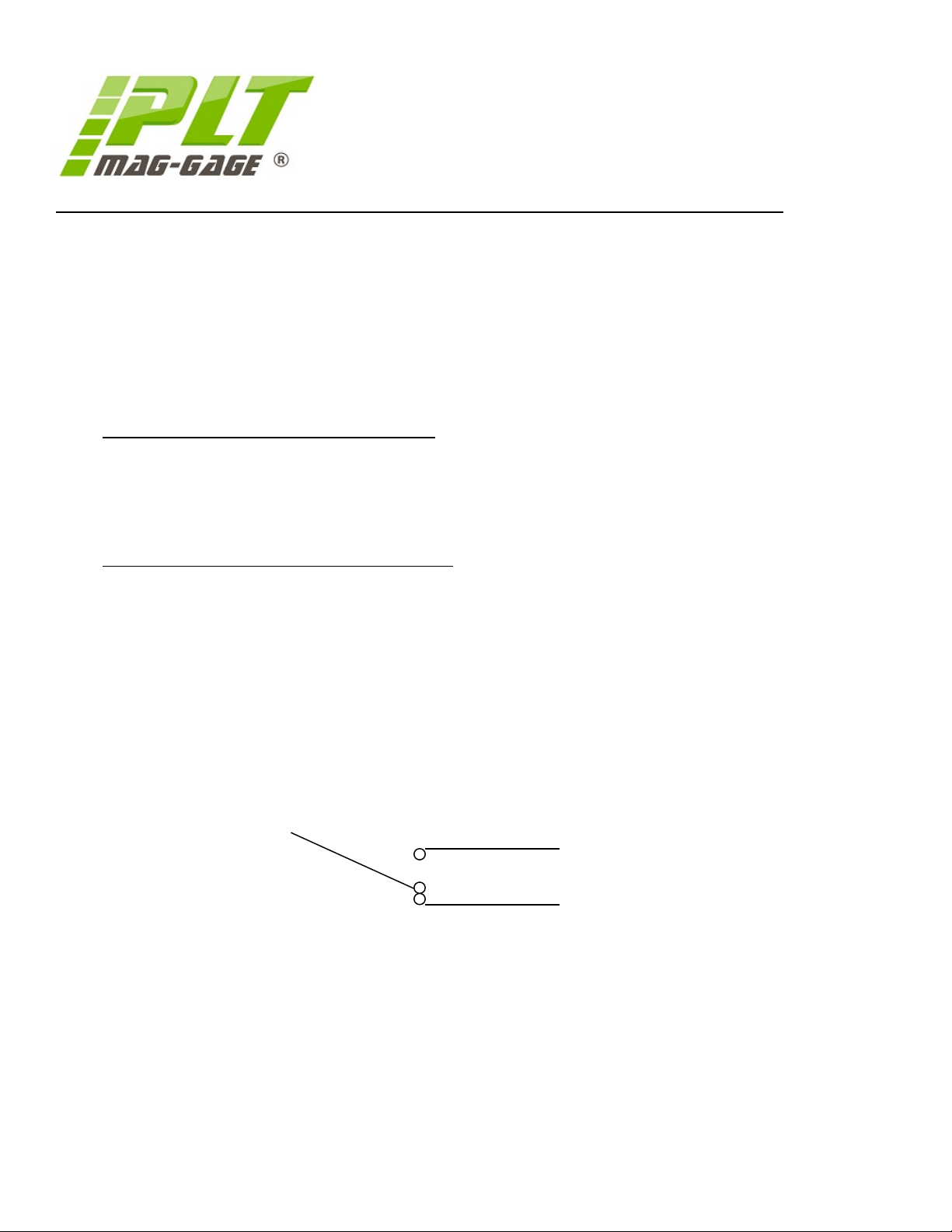
4.2.5 ELECTRICAL WIRING – RISING LEVEL
N/O Red Terminal 1 Closes on rising level.
C Green Terminal N
N/C Blue Terminal 2 Opens on rising level.
4.2.6 ELECTRICAL WIRING – FALLING LEVEL
N/C Red Terminal 1 Opens on falling level.
C Green Terminal N
N/O Blue Terminal 2 Closes on falling level.
(N) Green
(1) Red
(2) Blue
Electronic Level Control
Installation, Operation and Maintenance Instructions
OPS-001 Revision 6 Page 28 of 30 December 17, 2018
Page 29

Process Level Technology, Ltd.
MAG-GAGE®
Section 4.3.0. – Electric Level Switches (MGS-700EX(/2),MGS-900EX2(/2))
4.3.1 INTRODUCTION
The MGS-700/900EX and MGS-700/900EX2 are bistable-latching switches designed for Process Level
Technology, Ltd. MAG-GAGE® series gages only. The MGS-700/900EX has single pole double throw contacts
(SPDT) and the MGS-700/900EX2 has double pole, double throw contacts (DPDT). The switch will change state
when the float passes by it in a rising or falling level condition. The switch remains in a latched position until the
float passes the switch in the opposite direction.
4.3.2 SPECIFICATIONS MGS-700EX(/2) MGS-900EX(/2)
Maximum switching voltage: 250 VAC 250 VAC
Maximum switching current amps: 10.0 amps VAC 15.0amps VAC
Maximum switching wattage: 2500 watts VAC 3250 watts VAC
Maximum Temperature (standard): 350 degrees F 350 degree F
Maximum Temperature (HT option): 650 degrees F 650 degree F
Dead Band: 0.35 inch 0.35 inch
Electrical Area Classification: Class I Div I Grp. B,C,D
4.3.3 MOUNTING
The MGS-700EX/900EX,(/2) is mounted to the MAG-GAGE® chamber with all 316 Stainless Steel worm gear
pipe clamps. The switch must be mounted with TOP facing up. Rod mounted switch assemblies are available as
a factory installed option. Switch points can be changed at any time by loosening the clamps and sliding the
switch vertically to the desired set point.
4.3.4 OPERATION
When the switch is first installed, it is necessary to set the switch for normal operation. This is accomplished by
passing the float pass the switch, the chamber can be filled with liquid so the float will pass the highest switch
and then drained, or by manually sliding the switch pass the float in both directions. If the switch is being
positioned above the float, the float must pass in the down direction before installation and conversely if the
switch is positioned below the float.
Electronic Level Control
Installation, Operation and Maintenance Instructions
OPS-001 Revision 6 Page 29 of 30 December 17, 2018
Page 30
Process Level Technology, Ltd.
MAG-GAGE®
Section 4.3.0. – Electric Level Switches (MGS-700EX(/2), MGS-900EX2(/2))
Caution: If there is a need to take the switch out of service or disconnect it for any reason, then make the sure
the circuit is de-energized.
Note: Keep cover tightly closed when in operation. To prevent ignition of GRP. B atmospheres a approved
sealing fitting must be installed
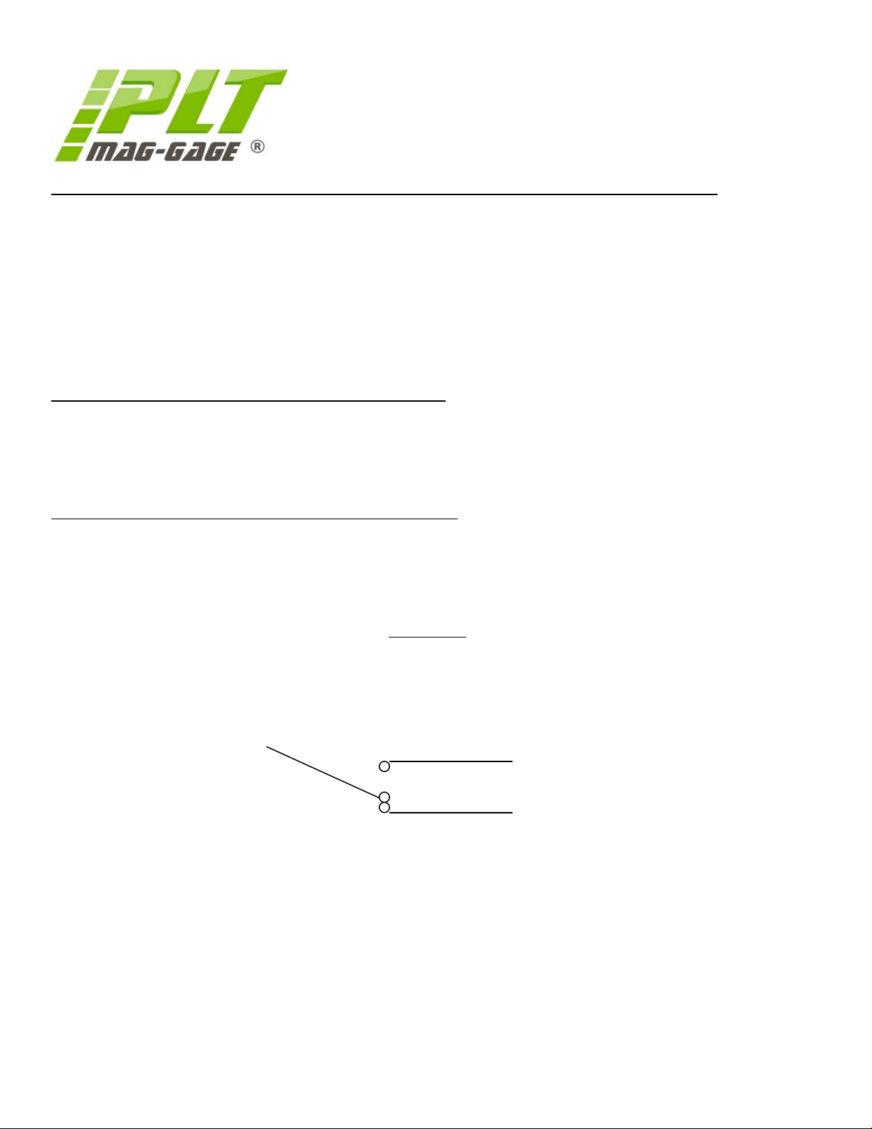
4.3.5 ELECTRICAL WIRING – RISING LEVEL
N/O Red Terminal 1(4) Closes on rising level.
C Green Terminal 2(5)
N/C Blue Terminal 3(6) Opens on rising level.
4.3.6 ELECTRICAL WIRING – FALLING LEVEL
N/C Red Terminal 1(4) Opens on falling level.
C Green Terminal 2(5)
N/O Blue Terminal 3(6) Closes on falling level.
*(#) DPDT
(N) Green
(1) Red
(2) Blue
OPS-001 Revision 6 Page 30 of 30 December 17, 2018
 Loading...