

Page 1
NEW
PLS5
PACIFIC LASER
SYSTEMS
The Professional Standard
OPERATING MANUAL
Page 2

Table of Contents
Welcome to PLS laser tools. We believe you have chosen the finest laser tool in
the world. We are committed to the highest quality standards in workmanship and
materials.
PLS laser tools were developed by contractors to provide every trade with accurate and
efficient alignment information. Thousands of our customers will attest to the savings of
time and money through the performance, convenience and versatility of PLS laser
tools.You can be confident of prompt service to your laser, should the need arise.
CONTENTS
Introduction ...................................
About The Company...............1A,1B
Maintenance .................................
Warranty..........................................
Features..........................................
Safety Labeling & Instructions.......
Beams.............................................
1
B
2
2
3
4
5
Plumb...........................................6
Level.............................................
Square.........................................
Check Calibration..............
Magnetic Bracket........................
Target..........................................
PLS5 Exterior System...........
PLS5 & PLS3 Specifications......16
9,10,11
14,15
1
7
8
12
13
Page 3

About Pacific Laser Systems
The PLS family of laser tools was developed to give contractors the ability to
transfer critical layout reference points for any job site task. All are self-leveling,
compact and durable laser alignment tools.
What sets PLS•Pacific Laser Systems apart from the rest? Built by contractors
for contractors, PLS tools were developed out of necessity by professionals with
over 50 years of experience in commercial and residential interior and exterior
layout. PLS founders were contractors first before becoming manufacturers of
the finest point-to-point alignment tools in the world.
Point-to-point reference means you can plumb with a PLS5 or PLS3 literally
from floor to ceiling or from 50 feet off the ground. With our PLS5, squaring or
layout of 90° angles can be done faster than ever before.
1A
Page 4

About Pacific Laser Systems
Our target market is the professional contractor who needs a dependable alignment tool that will speed production and save money. General Contractors and
project managers use the PLS laser to check existing conditions before work
begins. They also use it to judge the work performed by subcontractors.
Subcontractors use PLS lasers for layout on the job site. As much as 25% of the
work day can be spent on layout. The PLS5 system gives square reference easily and quickly. No more 3-4-5. The unique PLS cantilever design allows easy
sight of the opposing reference points and is proven to be effective in installing
curtain walls, foundations, columns, skylights, doors, cabinetry and much more.
The portability and utility of PLS lasers make them attractive alignment tools
when bubble vial levels or rotary lasers are too cumbersome or too limited to do
the job.
The PLS5 and PLS3 are registered trademarks of PLS•Pacific Laser Systems.
The PLS5 utilizes our patented technology, U.S. Patent No. 5,144,487.
1B
Page 5

Maintenance
Good care of the PLS3or PLS5is primarily common sense care. Remove the batteries from unit
if the laser is to be stored for a considerable period of time. Keep the optic windows clean using a
soft cloth or photographic grade cleaning tissue. Avoid storage conditions of prolonged heat or cold.
Warranty
Thisproduct is warranted by PLS • Pacific Laser Systems to the original purchaser to be free from
defects in material and workmanship under normal use for a period of three years from the date of
purchase. During the warranty period, and upon proof of purchase, the product will be repaired or
replaced (with the same or similar model at our option), without charge for either parts or labor
through PLS. The purchaser shall bear all shipping, packing and insurance costs. Upon completion of the repair or replacement, the unit will be returned to the customer, freight prepaid. The warranty will not apply to this product if it has been misused, abused or altered. Without limitingthe
foregoing, battery leakage, dents or gouges to the plastic housing, broken optic windows, damage
to the switch/LED membrane are presumed to result from misuse or abuse. Tampering with or
removal of the caution or certification labels voids this warranty.
Neither this warranty or any other warranty, express or implied, includingimpliedwarranties of merchantability, shall extend beyond the warranty period. No responsibility is assumed for any incidental or consequential damages. This warranty gives you specific legal rights, and you may have other
rights which vary from state to state.
There is nothing an owner can do in the way of service or maintenance on PLS tools. Contact
PLS or your local service center for repairs.
2
Page 6
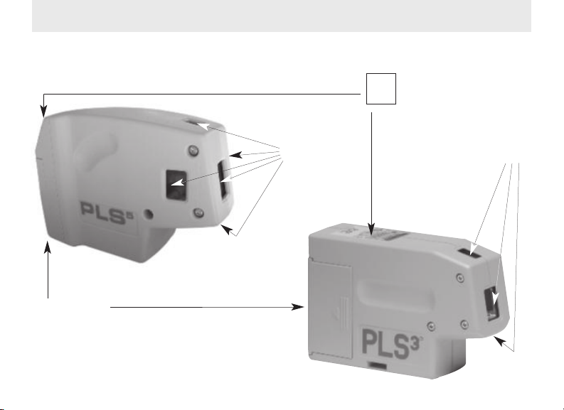
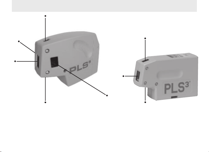
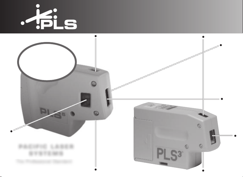
Features
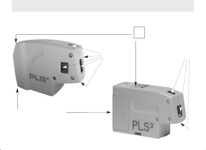
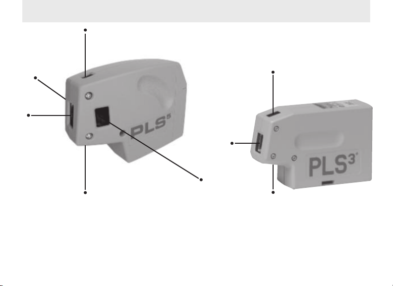
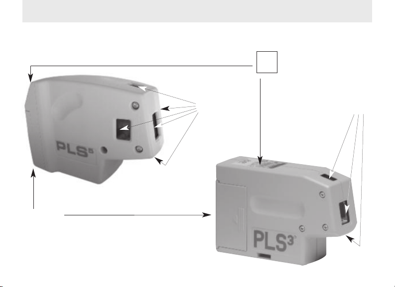
1/4 X 20 ACCESSORY MOUNT IN BASE OF EACH UNIT
BATTERY DOOR
USE EITHER 3AA 1.5V
ALKALINE OR NICAD
BATTERIES
3
OPTIC WINDOWS
(5)
INDICATOR LED
ON: GREEN
ON
TILT: RED
OFF
BATTERY LOW: AMBER
OPTIC WINDOWS
(3)
Page 7
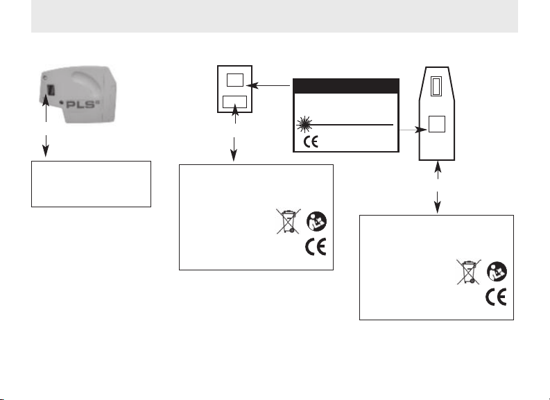
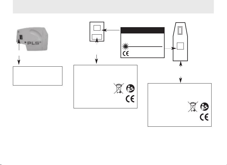
Safety Labeling & Instructions
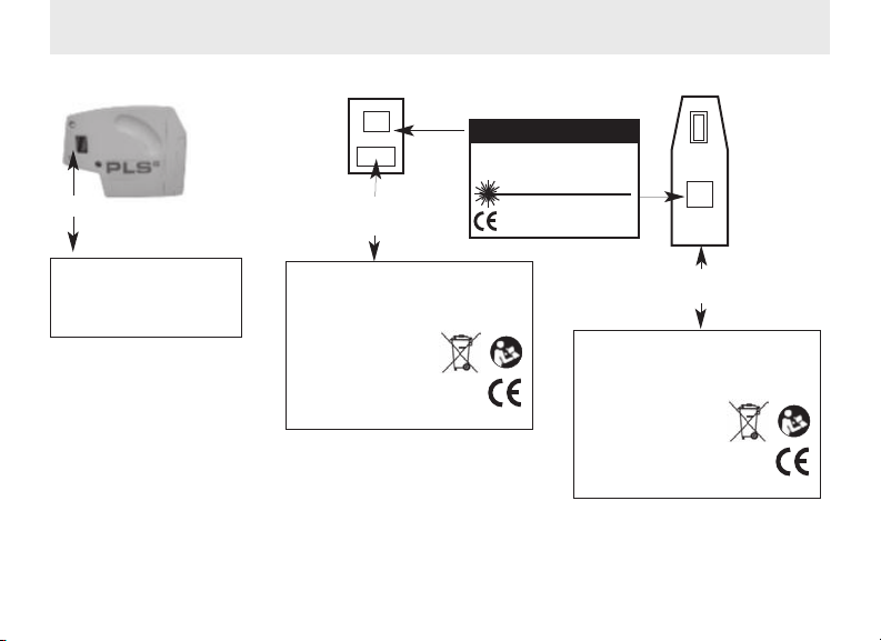
PLS5 SIDE
PLS5 BACK
PLS3 TOP
WARNING LABEL
CAUTION
LASER RADIATION
DO NOT STARE INTO BEAM OR VIEW
DIRECTLY WITH OPTICAL INSTRUMENTS
APERTURE LABEL
AVOID EXPOSURE
LASER RADIATION EMITTED
FROM THIS APERTURE
5
PLS
and PLS3comply with
US FDA performance standards,
21 CFR, Subchapter J.
5
The PLS
a semiconductor laser diode
and PLS3contain
with a wavelength of 635 nanometers.
The continuous output of any single beam never exceeds 1.0 milliwatts.
Never stare directly into the laser beam or view the beam with optical
instruments. Turn the laser off when not in use.
CAUTION: USE OF CONTROLS, ADJUSTMENTS OR PROCEDURES
OTHER THAN THOSE SPECIFIED HEREIN MAY RESULT IN HAZARDOUS RADIATION EXPOSURE.
These labels are attached to every PLS laser. These are not to be removed or defaced.
ID# CERTIFICATION LABEL
GLOBALLY SOURCED. FINALASSEMBLY IN U.S.A.
PATENT #6,938,360 1-800-601-4600
PLS 2550 KERNER BLVD., SAN RAFAEL, CA 94901
S/N:
CLASS 2 LASER PRODUCT
PLS5COMPLIES WITH FDA STDS. 21. CFR.,
CHAP. J 1040.10 & 11 EXCEPT FOR DEVIATION
PURSUANT TO LASER NOTICE .60 OF 7/26/2006
REGISTERED U.S. PATENT OFFICE.
DATE:
MAX OUTPUT POWER <1mW
WAVELENGTH 635-670nm
CLASS 2 LASER PRODUCT
ID# CERTIFICATION LABEL
GLOBALLY SOURCED. FINALASSEMBLY IN U.S.A.
PATENT #6,938,360 1-800-601-4600
PLS 2550 KERNER BLVD., SAN RAFAEL, CA 94901
S/N:
CLASS 2 LASER PRODUCT
PLS3COMPLIES WITH FDA STDS. 21. CFR.,
CHAP. J 1040.10 & 11 EXCEPT FOR DEVIATION
PURSUANT TO LASER NOTICE .60 OF 7/26/2006
DATE:
4
Page 8
#3
Beams
#5
#1
PLS
#2
5
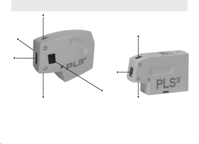
The five beams of the PLS5are: #1 Forward Beam, #2 Down Beam, #3 Up Beam,
#4
#3
#1
#2
#4 Left Beam, #5 Right Beam. All PLS5 beams have the same brightness and are
square to each other.
3
PLS
The three beams of the PLS3are: #1 Forward Beam, #2 Down Beam, #3 Up Beam.
5
Page 9
Plumb
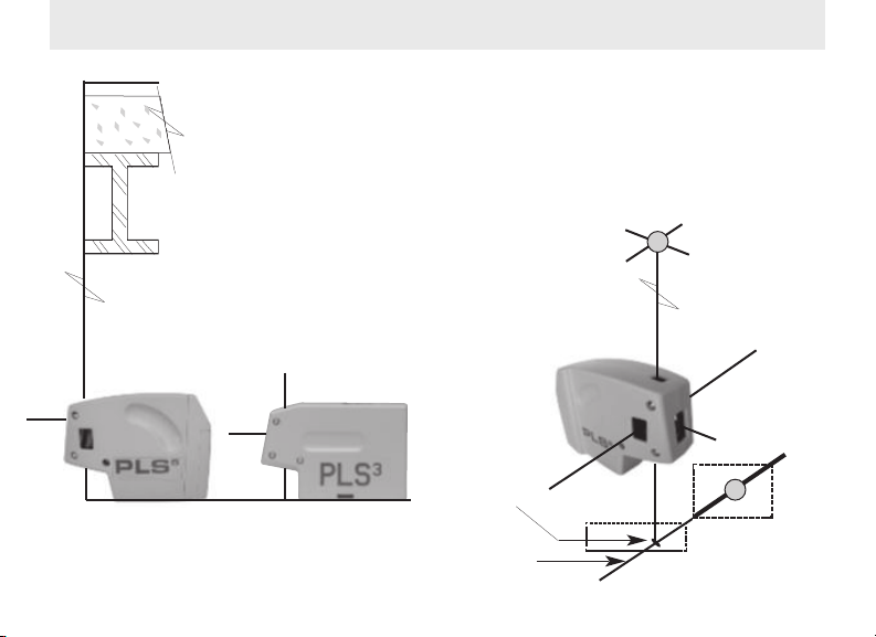
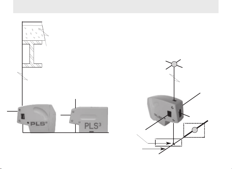
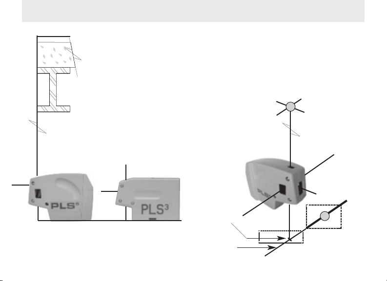
To establish plumb with the PLS5and PLS3, place the #2 down beam over the mark to be
transposed. See Fig.1. The #3 up beam is exactly plumb within specification. You can
shoot plumb marks down and up, or cantilevered over the edge of a building/shaft opening
or floor track, etc. See Fig.2. Use the floor stand with your PLS5or PLS3to increase the
sight angle of the #2 down beam.
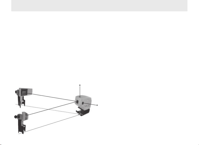
The PLS3and PLS5can quickly survey existing conditions for plumb. Use a tape
and #3 up beam. Position the laser near the structure.
Check any distance up or down the structure. It is also
possible to transpose marks from a roof or ceiling down to
the floor. Move the laser until the #3 up beam hits the edge or
center of the ceiling component to be transposed. Mark the
floor at the #2 down beam. See Fig. 2 and 3.
#3
FIG. 2
FIG. 3
PLUMB
POINT
FLOOR
LAYOUT
FIG. 1
#2
CENTER BEAM
ON LAYOUT
6
Page 10
Level
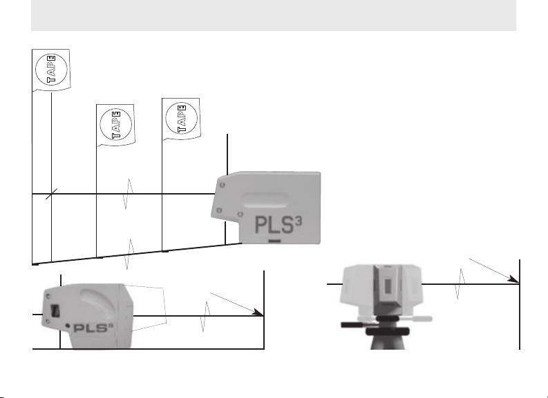
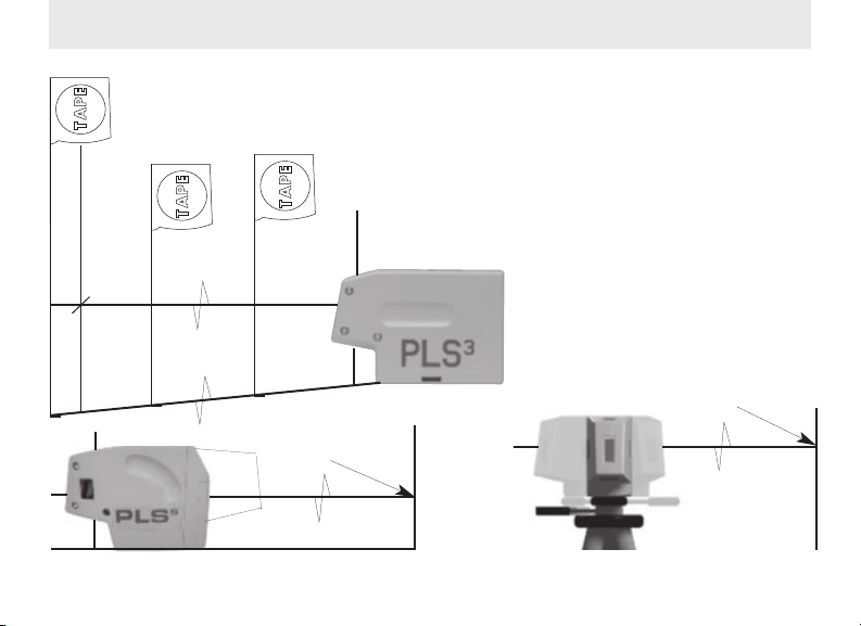
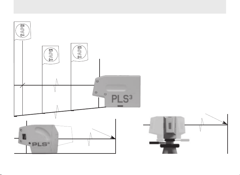
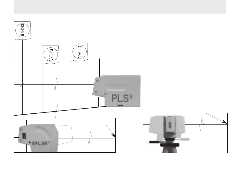
Precise level and grade marks are easily established with the PLS5and PLS3. Swivel the
unit about its center, stopping to mark the desired level or grade points. See Fig. 4. Any
TAPE
stable surface can be used. When mounted on a tripod or wall mount, swivel and mark.
TAPE
20’
10’
See Fig. 5.When turning your PLS
be sure tripod head is perfectly level. Error in marks can
result with tripod out of level.
TAPE
To survey existing conditions for level,
point in the direction to survey. Using
a tape or rod with a bench mark, the
variations in level or grade can be
noted quickly at various distances.
See Fig. 6.
5
or PLS3on a tripod
FIG.6
MARK
MARK
FIG. 4
FIG. 5
7
Page 11
Square
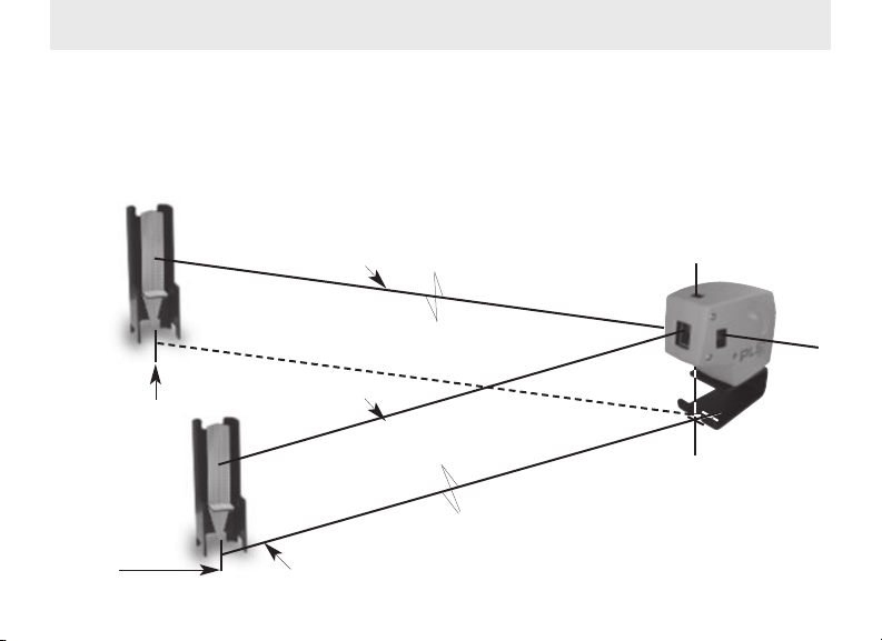
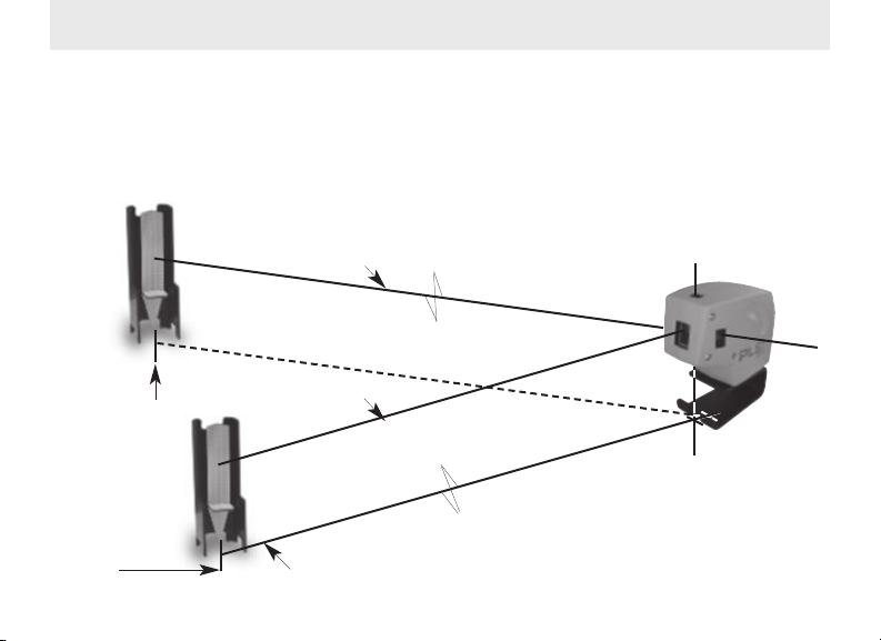
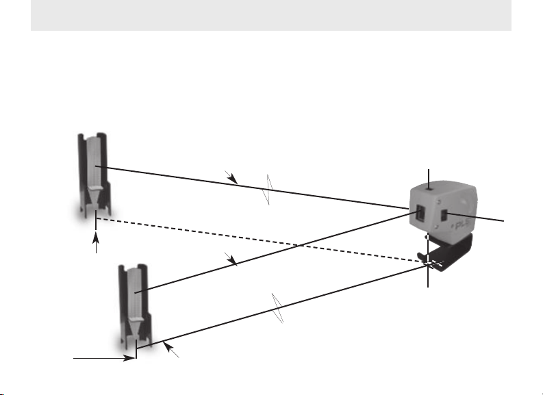
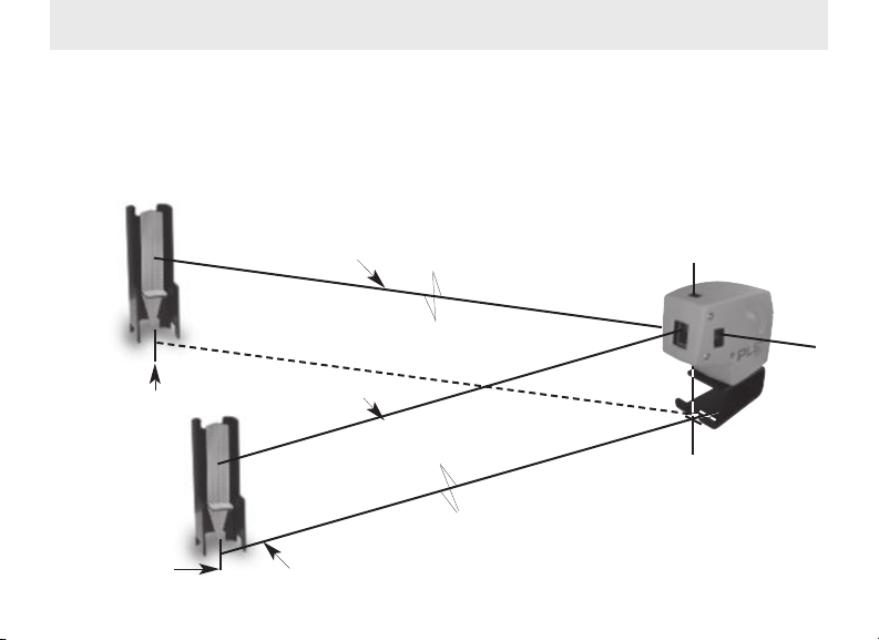
To establish square, place the PLS5with the #2 down beam over the layout reference line. See Fig.
7. Place the pendulum target on that line, and center #1 forward beam on the center of the target.
Once centered, move the pendulum target to square on #4 left beam or #5 right beam. Make a
mark on the floor or surface near the laser and the second mark at the desired distance from the
laser. See Fig. 7.
BEAM #5
C
L
MARK
C
L
MARK
BEAM #1
FIG. 7
LAYOUT OR REFERENCE LINE
8
Page 12
Checking Calibration
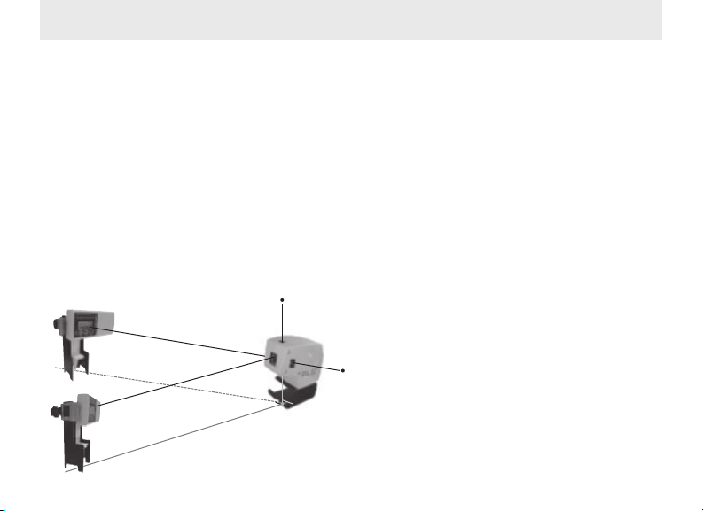
There are several easy methods to check the calibration and accuracy of the PLS5and PLS3.
We recommend that you check this periodically.
5
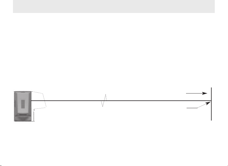
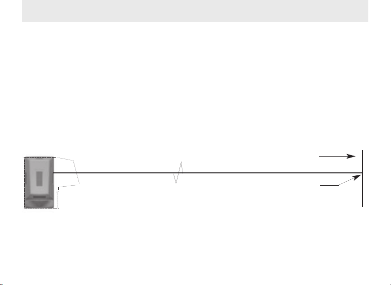
METHOD 1 (PLS
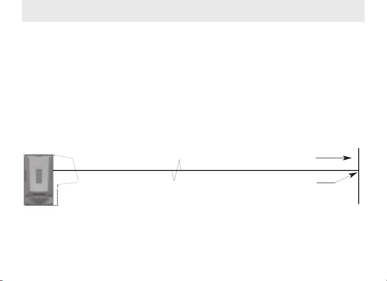
surface 25’-0” or more from a suitable wall or target. See Fig. 8. Point the #1 forward beam at
the wall or target and carefully mark the center of elevation. Swivel the PLS590° on its center
until the #5 right beam is over the first mark. Check to see if there is any difference in elevation
from the center of #1 forward beam and the center of #5 right beam. Repeat to check #4 beam.
At 50’-0” the difference should not be greater than 1/8.” At 25’-0” the difference should not be
greater than 1/16.”
only) Quick Check of Performance Accuracy. Place the PLS5on a stable
WALL OR TARGET
MARK
FIG. 8
9
Page 13

Checking Calibration
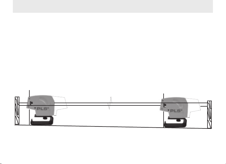
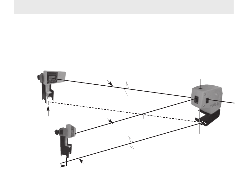
METHOD 2 (both PLS5and PLS3) Exact Check of Level Accuracy. Find a fairly level site line
(preferably a concrete slab) 25’-0” or greater with two opposing walls. You can also use scrap
2 x 4s, for example, as targets. See Fig. 9. Place the laser about 6” from target #1, and carefully
mark the elevation of #1 forward beam on the target. Swivel the laser 180° on its center. Mark
the elevation center of #1 forward beam on target #2. Move the laser to target #2. At 6” from the
target, mark the center of elevation of #1 forward beam on target #2. Swivel the laser on its center and mark center of elevation at target #1. You now have two centers of elevation at each target. Carefully measure the distance between centers of each set of marks. If the distance is the
same, the laser is exactly level. If there is a difference, subtract one measurement from the other.
This method magnifies any error by a factor of two. Therefore, divide this difference by two to find
the exact error of level. The maximum error for the PLS
maximum error for the PLS3is 1/8” at 25’-0” or 1/4” at 50’-0.”
5
is 1/16” at 25’-0” or 1/8” at 50’-0.” The
TARGET #1
FIG. 9
TARGET #2
10
Page 14
Checking Calibration
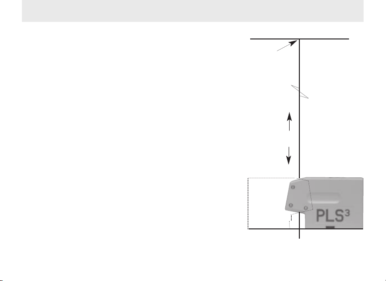
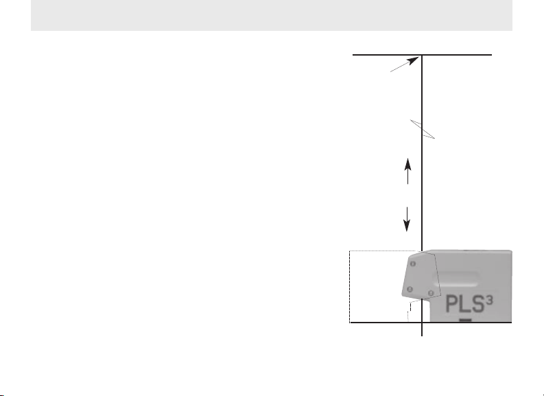
METHOD 3 (both PLS5and PLS3) Exact Check of Plumb
Accuracy. This requires significant vertical height (minimum 10’-0”) and the ability to mark at that height. Place
the unit with the #2 down beam exactly centered on both
axes over a cross mark. See Fig. 10. At the surface
above, mark both axes of #3 up beam. Rotate the laser
180° and place the #2 down beam exactly centered on the
same mark. The #3 up beam should be exactly over the
first mark.
MARK
If there is a difference between mark #1 and mark #2,
the error of the plumb beam is one half that difference.
11
DISTANCE
FIG. 10
Page 15
Magnetic Bracket Instructions
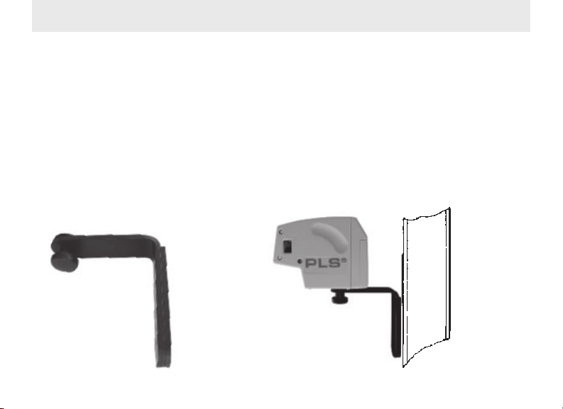
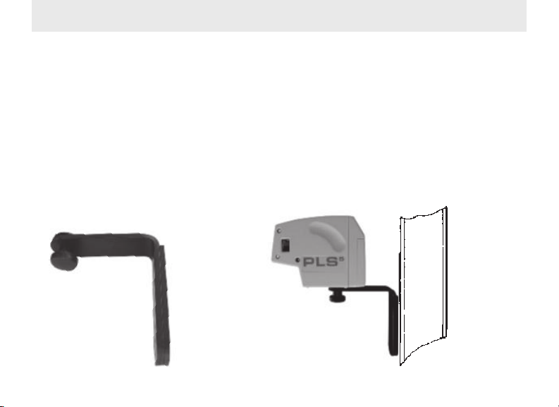
To use the magnetic bracket with the PLS laser:
1. Screw the 1/4 x 20 threaded knob to the mount on the base of the PLS laser.
2. Mount the PLS laser and bracket to steel studs, steel door frame, I-beams, carpenter’s
square, etc.
3. Rotate the PLS laser to desired point and make your mark.
Combine the PLS laser, the magnetic bracket, a standard steel carpenter’s framing square and one
or more clamps and you have the ability to mount the laser in unlimited ways. Clamp carpenter’s
square to concrete forms, ladders, wood studs, etc. Attach the PLS laser with magnetic mount as
described above. If you drill two small holes centered on the long section of the carpenter’s square,
the square can be attached to unfinished drywall partitions with screws or removable nails. Slide
the PLS laser up and down the mounted carpenter’s square to the precise desired height.
STEEL STUD
FIG. 11
FIG. 12
12
Page 16

Pendulum Target
Use the PLS5pendulum target for a variety of time saving alignment tasks. For square: For consistent accuracy in establishing or checking square, use the PLS5target to transfer the laser
beam to the floor surface. To establish square, see page 8 of this manual. Always mount the
5
laser on the floor stand when establishing square. The pendulum target is designed so the
PLS
beams are best seen at this height.
For transfer of vertical lines:
To transfer vertical marks quickly and accurately to a wall:
1. Place the front of the PLS
forward beam on the mark to be transferred. (If the mark is on the
floor, place the #2 down beam over the mark.)
2. Place the target with its back flat against the wall at the desired
height and move the target until the #3 up beam is centered on
the plastic lined target.
3. Mark the top or bottom of the target arrow pins.
5
laser against the wall with the #1
PENDULUM TARGET
FIG. 13
13
Page 17
PLS5 System Interior - Exterior System
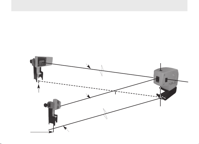
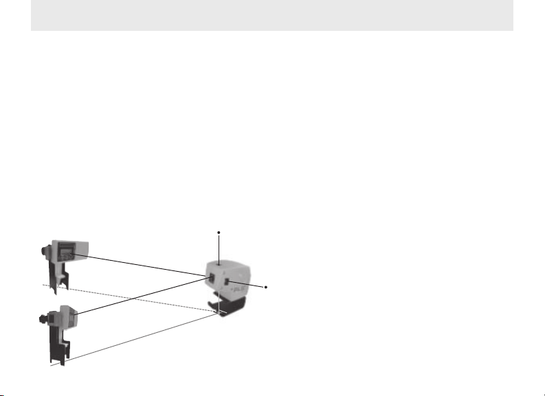
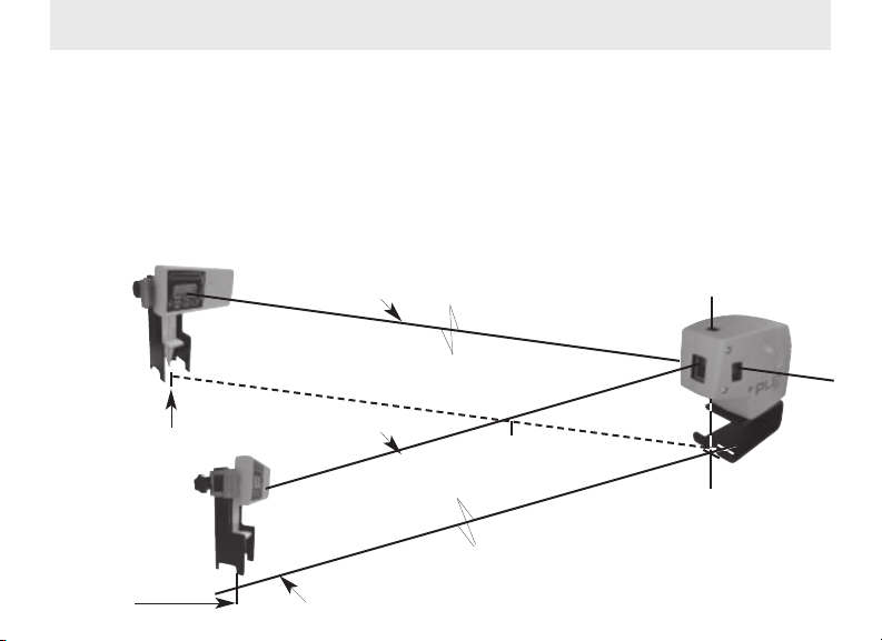
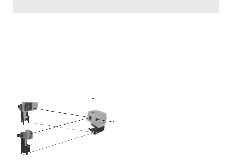
The PLS5 is the only point-to-point layout tool for use on both indoor and outdoor job
sites. Bright sunshine has traditionally limited the use of visible beam lasers to interior
projects. The PLS5 partnered with our laser receiver gives the contractor the ability to
accurately lay out a job site up to 250 + feet, even in the brightest outdoor conditions.
The PLS5 can also be used inside, without the receiver, for all point-to-point
alignment tasks.
“Beep
Beep”
C
L
MARK
“Beep
Beep”
C
L
MARK
BEAM #5
BEAM #1
FIG. 7
LAYOUT OR REFERENCE LINE
14
Page 18
PLS5 Exterior Applications
CONCRETE CONSTRUCTION
• Layout of batter boards
• Layout & alignment for masonry projects
• Layout for saw cutting (control joints)
• Alignment of anchor & J bolts
• Layout & alignment of piers and
column footings
• Layout of form boards for concrete
flatwork
“Beep Beep”
“Beep Beep”
15
ELECTRICAL AND MECHANICAL
CONSTRUCTION
• Rough-in of conduit
• Rough-in of waste and supply lines
• Rough-in of natural gas supply lines
FRAMING CONSTRUCTION
• Layout of control lines on concrete
slabs, decking and sub-floors
• Alignment of exterior heavy gauge
steel framing
• Layout & alignment for commercial &
residential wood framing
GLAZING CONSTRUCTION
• Layout & install of curtain walls &
storefront projects.
Page 19

Specifications
5
Light Source: Semiconductor laser diode Semiconductor laser diode
Working range: +/- 100 feet +/-100 feet
Accuracy: < 1/8” @ 100 feet < 1/4” @ 100 feet
Leveling: Automatic Automatic
Leveling range: +/- 6° +/- 6°
Power supply: 3 AA batteries, alkaline or 3 AA batteries, alkaline or
Operating time: + 30 hrs. continuous use + 30 hrs. continuous use
Operating temp.: 0° F to 122° F 0° F to 122° F
Storage temp.: -40° F to 158° F -40° F to 158° F
Indicators: Green light: ON Green light: ON
Environmental: Water resistant; not Water resistant; not
Dimensions: 2” X 4” X 4 3⁄4 “ 1 3/4” x 5” x 3 1/4”
Weight (with batteries): 1.13 lbs. ( .52 kg. ) 12 oz. (.33 kg.)
PLS
510-650nM, visible 510-650nM, visible
(<3mm @ 30 meters) (<6mm @ 30 meters)
rechargeable rechargeable
(-18° C to 50° C) (-18° C to 50° C)
(-40° C to 70° C) (-40° C to 70° C)
Red light: EXCEEDS Red light: EXCEEDS
TILT TILT
Amber light: BATTERY Amber light: BATTERY
LOW LOW
submersible submersible
PLS
3
16
Page 20

PLS Lab Technicians
PLS•Pacific Laser Systems
2550 Kerner Blvd., San Rafael, CA 94901
www.plslaser.com • 800 601 4500
Page 21
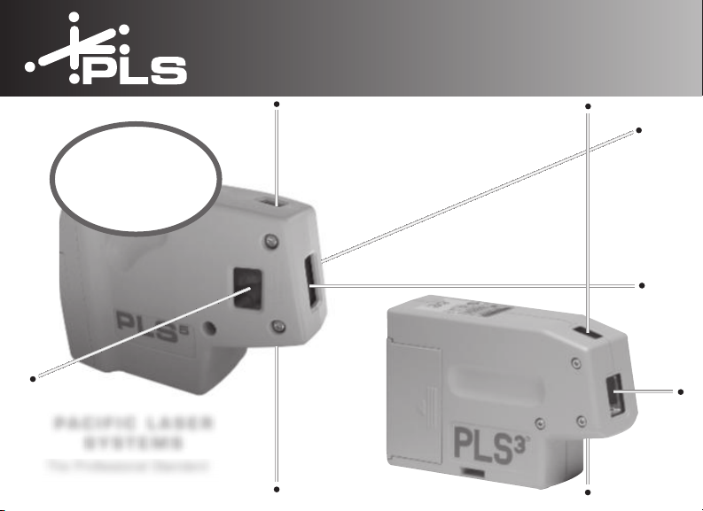
NUEVO
PLS5
PACIFIC LASER
SYSTEMS
The Professional Standard
MANUAL DE INSTRUCCIONES
Page 22

ÍNDICE
Bienvenido a las herramientas láser PLS. Creemos que ha seleccionado la mejor herramienta láser en el mundo. Estamos comprometidos con las más altas normas de calidad en mano de obra y materiales.
Las herramientas láser PLS fueron creadas por contratistas a fin de proporcionar a cada
comercio información precisa y eficaz sobre alineación. Miles de nuestros clientes darán
fe del ahorro de tiempo y dinero que se logra a través del rendimiento, la conveniencia
y la versatilidad de las herramientas láser PLS. Además, en el caso de que surja la
necesidad, puede confiar en un servicio inmediato para su láser.
CONTENIDO
Introducción ............................................1
Mantenimiento ....................................... 2
Garantía.................................................. 2
Características........................................ 3
Etiquetas de seguridad e instrucciones.. 4
Haces......................................................5
Plomada...................................................6
1
Nivel................................................... 7
Escuadra............................................ 8
Verificar calibración................. . 9,10.11
Soporte magnético............................12
Objetivo..............................................13
PLS 5 sistema exterior.................14,15
Especificaciones de PLS5 y PLS3....16
Page 23

Mantenimiento
Un buen mantenimiento del PLS3 o PLS5 requiere principalmente cuidado sensato. Retire las
baterías de la unidad si guardará el láser durante un tiempo considerable. Mantenga las ventanas
ópticas limpias. Use un paño suave o papel de limpieza fotográfico. Evite guardarlo en lugares con
calefacción o frío prolongado.
Garantía
PLSoPacific Laser Systems garantiza al comprador original que este producto no tendrá defectos
de materiales ni mano de obra en circunstancias de uso normal durante un período de un año a
partir de la fecha de compra. Durante el período de garantía y presentando prueba de compra, el
producto será reparado o reemplazado (por un modelo igual o similar según nuestro criterio), sin
cobro por los repuestos o la mano de obra, a través de PLS. El comprador se hará cargo de todos
los costos de envío, empaque y seguro. Una vez completada la reparación o el reemplazo, la
unidad será devuelta al cliente, con flete previamente pagado. La garantía no se aplicará si el producto ha sido mal utilizado, maltratado o alterado. Además de lo anterior, el derrame de la pila, las
abolladuras o gubias en la cubierta plástica, la rotura de las ventanas ópticas, el daño del interruptor o la membrana del indicador luminoso se consideran consecuencia del mal uso o maltrato.
Alterar o retirar las etiquetas de precaución o certificación anula esta garantía.
Ni esta garantía, ni ninguna otra, expresa o implícita, incluidas las garantías implícitas de comerciabilidad, se extenderá más allá del período estipulado. No se asume ninguna responsabilidad por
daños imprevistos o consecuentes. Esta garantía le otorga derechos legales específicos y usted
podría tener otros derechos que varían según el estado.
El usuario no puede hacer nada para realizar servicio o mantenimiento en las herramientas
PLS. Comuníquese con PLS en su centro de servicio local para reparaciones.
2
Page 24
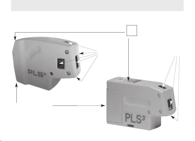
Características
MONTAJE PARA ACCESORIOS DE 1/4 X 20 EN LA BASE DE CADA UNIDAD
VENTANAS ÓPTICAS
PUERTA PARA LA BATERÍA
UTILICE 3 PILAS ALCALINAS
AA DE 1.5 V O NICAD
3
(5)
ILED INDICADOR
ENCENDIDO: VERDE
ON
INCLINACIÓN: ROJO
OFF
BATERÍA BAJA ÁMBAR
VENTANAS ÓPTICAS
(3)
Page 25
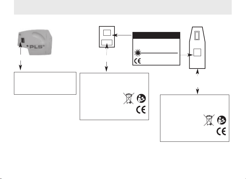
Etiquetas de seguridad e instrucciones
LADO DEL PLS5
PARTE POSTERIOR DEL PLS5
ETIQUETA DE ADVERTENCIA
PARTE SUPERIOR DEL PLS3
PRECAUCIÓN
RADIACIÓN LÁSER
NO MIRE DIRECTAMENTE AL HAZ DE
LUZ NI CON AYUDADE
INSTRUMENTOS ÓPTICOS
POTENCIA MÁX. DE EMISIÓN <1MW
ETIQUETA DE ABERTURA
EVITE EXPOSICIÓN
EMISIÓN DE RADIACIÓN LÁSER
DESDE ESTA ABERTURA
PLS5 y PLS3 cumplen con las
normas de rendimiento de la
FDA de Estados Unidos, 21
CFR (Código de Regulaciones
Federales), Subcapítulo J.
PLS5 y PLS3 contienen un diodo láser semiconductor
con una longitud de onda de 635 nanometros. La salida continua de un haz
único nunca excede 1.0 miliwatts. Nunca mire directamente en el haz láser ni
lo mire con instrumentos ópticos. Apague el láser cuando no lo use.
N.º DE ETIQUETA DE CERTIFICACIÓN
GLOBALLY SOURCED. FINALASSEMBLY IN U.S.A.
PATENT #6,938,360 1-800-601-4600
PLS 2550 KERNER BLVD., SAN RAFAEL, CA 94901
S/N:
CLASS 2 LASER PRODUCT
PLS5COMPLIES WITH FDA STDS. 21. CFR.,
CHAP. J 1040.10 & 11 EXCEPT FOR DEVIATION
PURSUANT TO LASER NOTICE .60 OF 7/26/2006
REGISTRADO EN LA OFICINA DE PATENTES DE EE.UU.
DATE:
LONGITUD DE ONDA 635-670NM
PRODUCTO LÁSER DE CLASE II
N.º DE ETIQUETA DE
CERTIFICACIÓNCERTIFICACIÓN
GLOBALLY SOURCED. FINALASSEMBLY IN U.S.A.
PATENT #6,938,360 1-800-601-4600
PLS 2550 KERNER BLVD., SAN RAFAEL, CA 94901
S/N:
CLASS 2 LASER PRODUCT
PLS3COMPLIES WITH FDA STDS. 21. CFR.,
CHAP. J 1040.10 & 11 EXCEPT FOR DEVIATION
PURSUANT TO LASER NOTICE .60 OF 7/26/2006
DATE:
PRECAUCIÓN: EL USO DE CONTROLES, AJUSTES O PROCEDIMIENTOS DIFERENTES A LOS AQUÍ
ESPECIFICADOS PUEDE ORIGINAR UNA EXPOSICIÓN PELIGROSA A LA RADICACIÓN.
Estas etiquetas están adheridas a todos los láseres PLS. No deben retirarse ni dañarse.
4
Page 26
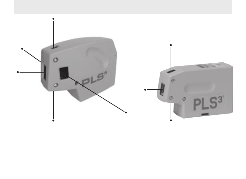
#3
Haces
#5
#1
#2
5
PLS
Los cinco haces del PLS5 son: N.º 1 Haz de avance, N.º 2 Haz hacia abajo, N.º 3 Haz hacia
#4
#3
#1
#2
arriba, N.º 4 Haz izquierdo, N.º 5 Haz derecho. Todos los haces del PLS5 tienen el mismo brillo y
están en escuadra entre sí.
3
PLS
Los tres haces del PLS3 son: N.º 1 Haz de avance, N.º 2 Haz hacia abajo, N.º 3 Haz
hacia arriba.
5
Page 27
Plomada
Para establecer la plomada con el PLS5 y PLS3, coloque el haz hacia abajo N.º 2 sobre la marca que
debe transponer. Consulte la Fig.1. El haz hacia arriba N.º 3 está a plomada exacta según las especificaciones. Puede efectuar marcas de plomada hacia abajo y arriba, o en voladizo sobre el borde de la abertura de un edificio/eje o pista del piso, etc. Consulte la Fig.2. Use la base del piso con el PLS5 o PLS3
para aumentar el ángulo de visualización del haz hacia abajo N.º 2.
El PLS3 y PLS5 pueden sondear rápidamente condiciones existentes para plomada. Use una cinta
y el haz hacia arriba N.º 3. Coloque el láser cerca de la estructura.
Compruebe la distancia hacia arriba o hacia abajo de la estructura.
También es posible transponer marcas desde un techo hacia el
piso. Mueva el láser hasta que el haz hacia arriba N.º 3 dé con el borde o
el centro del componente del techo que debe transponer. Marque el
piso en la marca del haz hacia abajo N.º 2. Consulte las Figs. 2 y 3.
#3
FIG. 2
FIG. 3
PLOMADA
PUNTO
PISO
REPLANTEO
FIG. 1
#2
HAZ CENTRAL
EN REPLANTEO
6
Page 28
Nivel
PLS5 y PLS3 permiten establecer marcas precisas de nivel y de nivel en tierra. Gire la
unidad sobre su centro y deténgase para marcar el nivel deseado o los puntos de nivel en
tierra. Consulte la Fig. 4. Se puede usar cualquier superficie estable. Cuando se use sobre
TAPE
20’
TAPE
10’
un trípode o montaje en la pared, gire y marque. Consulte la Fig.
5. Cuando utilice el PLS5 o PLS3 sobre un trípode,
asegúrese de que la cabeza del trípode esté perfectamente nivelada. Un trípode mal nivelado puede producir
TAPE
FIG.6
errores en las marcas.
Para sondear condiciones existentes
en relación con el nivel, apunte en la
dirección para sondear.Use una cinta
o varilla con un punto de referencia
para anotar rápidamente las variaciones en el nivel o el nivel a tierra a
diferentes distancias. Consulte la
Fig. 6.
MARCA
MARCA
FIG. 4
FIG. 5
7
Page 29
Escuadra
Para establecer la escuadra, coloque el PLS5 con el haz hacia abajo N.º 2 sobre la línea de referencia del replanteo. Consulte la Fig. 7. Coloque el objetivo del péndulo en esa línea y el haz de
avance N.º central en el centro del objetivo. Una vez centrado, mueva el objetivo del péndulo
en escuadra en el haz izquierdo N.º 4 o el haz derecho N.º 5. Haga una marca en el piso o la
superficie cerca del láser y una segunda marca en la distancia deseada desde el láser. Consulte
la Fig. 7.
HAZ N.º 5
C
L
MARCA
C
L
MARCA
HAZ N.º 1
FIG. 7
LÍNEA DE REPLANTEO O REFERENCIA
8
Page 30
Verificación de la Calibración
Hay varios métodos fáciles que le permiten verificar la calibración y exactitud del PLS5 y PLS3.
Le recomendamos que realice estas verificaciones periódicamente.
Método 1 (sólo PLS5) Verificación rápida de la exactitud de rendimiento.
Coloque el PLS5 en una superficie
estable a 25'-0” o más de distancia de una pared u objetivo adecuado. Consulte la Fig. 8.
Coloque el haz de avance N.º 1 en
la pared u objetivo, y marque detenidamente el centro de elevación. Gire el PLS5 90° sobre su centro hasta que el haz derecho N.º 5 esté sobre la primera marca. Compruebe si hay alguna diferencia en la elevación desde el centro del haz de avance N.º 1 y el centro del haz derecho N.º 5.Repita
para verificar el haz N.º 4. A 50'-0”, la diferencia no debe ser superior a 1/8”. A 25'-0”, la diferencia
no debe ser superior a 1/16”.
PARED U OBJETIVO
MARCA
FIG. 8
9
Page 31
Verificación de la Calibración
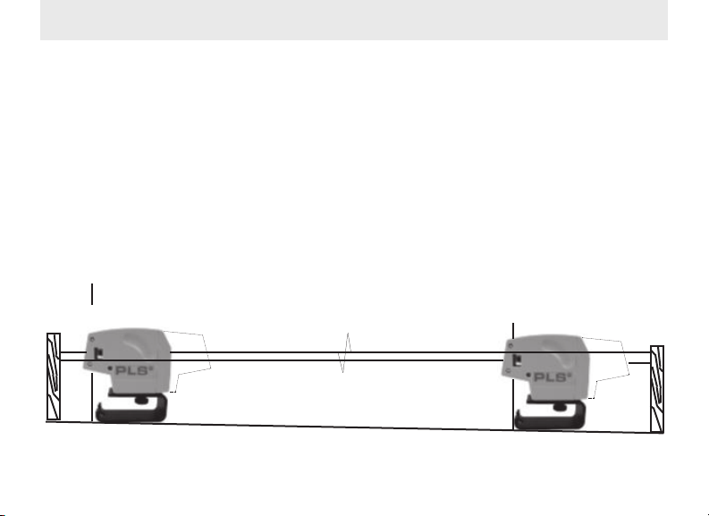
Método 2 (PLS5 y PLS3) Verificación exacta de la precisión del nivel. Busque una línea en un
sitio con una nivelación adecuada (preferiblemente una losa de hormigón) de 25'-0” o más con
dos paredes opuestas. También puede usar material de desecho
2 x 4, por ejemplo, como objetivos. Consulte la Fig. 9. Coloque el láser aproximadamente a 6” del
objetivo N.º 1 y marque cuidadosamente la elevación del haz de avance N.º 1 sobre el objetivo.
Gire el láser 180° sobre su centro. Marque el centro de elevación del haz de avance N.º 1 en el
objetivo N.º 2. Mueva el láser al objetivo N.º 2. A 6” de distancia del objetivo, marque el centro de
elevación del haz de avance N.º 1 en el objetivo N.º 2. Gire el láser sobre su centro y marque el
centro de elevación en el objetivo N.º 1. Ahora tiene dos centros de elevación en cada objetivo.
Mida cuidadosamente la distancia entre los centros de cada conjunto de marcas. Si la distancia
es la misma, el láser está exactamente nivelado. Si hay una diferencia, reste una medición a la
otra. Este método magnifica una o dos veces los errores. Por lo tanto, divida esta diferencia por
dos para conocer el error de nivelación exacto. El error máximo para el PLS5 es 1/16” a 25'-0” o
1/8” a 50'-0”. El error máximo para el PLS3 es 1/8” a 25'-0” o 1/4” a 50'-0”.
OBJETIVO N.° 1
FIG. 9
OBJETIVO N.° 2
10
Page 32
Verificación de la Calibración
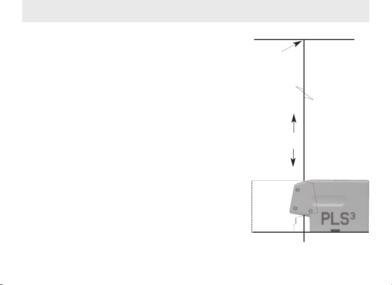
Método 3 (PLS5 y PLS3) Verificación exacta de la precisión
de la plomada. Esto requiere altura vertical significativa (mínimo de 10'-0”) y la posibilidad de realizar marcas a esa altura.
Coloque la unidad con al haz hacia abajo N.º 2 exactamente
en el centro de ambos ejes sobre una marca de cruz. Consulte
la Fig. 10. En la superficie arriba, marque ambos ejes del haz
hacia arriba N.º 3. Gire el láser 180° y coloque el haz hacia
abajo N.º 2 exactamente en el centro en la misma marca. El
haz hacia arriba N.º 3 debe estar exactamente sobre la
primera marca.
Si hay una diferencia entre la marca N.º 1 y la marca N.º 2,
el error del haz de plomada es responsable de mitad de l
a diferencia.the error of the plumb beam is one half that
difference.
11
MARCA
DISTANCIA
FIG. 10
Page 33
Objetivo de Péndulo
Use el objetivo de péndulo de PLS5 para ahorrar tiempo en una amplia variedad de tareas de alineación. Para
escuadra: Para alcanzar una precisión coherente en establecer o verificar la escuadra, use el objetivo del PLS5
para transferir el haz láser a la superficie del piso. Para establecer escuadra, consulte la página 8 de este manual. Siempre monte el láser PLS5 en la base del piso al establecer escuadra. El objeto de péndulo está diseñado de modo que los haces se observen mejor a esta altura.
Para la transferencia de líneas verticales:
Para transferir marcas verticales de forma rápida y precisa a una pared:
1. Coloque la parte frontal del láser PLS5 contra la pared con el haz de avance N.º 1en la marca que desea
transferir. (Si la marca está en el piso, coloque el haz hacia abajo N.º 2 sobre la marca).
2. Coloque el objetivo con su parte plana posterior contra la pared a la altura deseada y mueva el objetivo hasta
que el haz hacia arriba N.º 3 esté en el centro del objetivo alineado de plástico.
3. Marque la parte superior o inferior de las clavijas de flechas del objetivo.
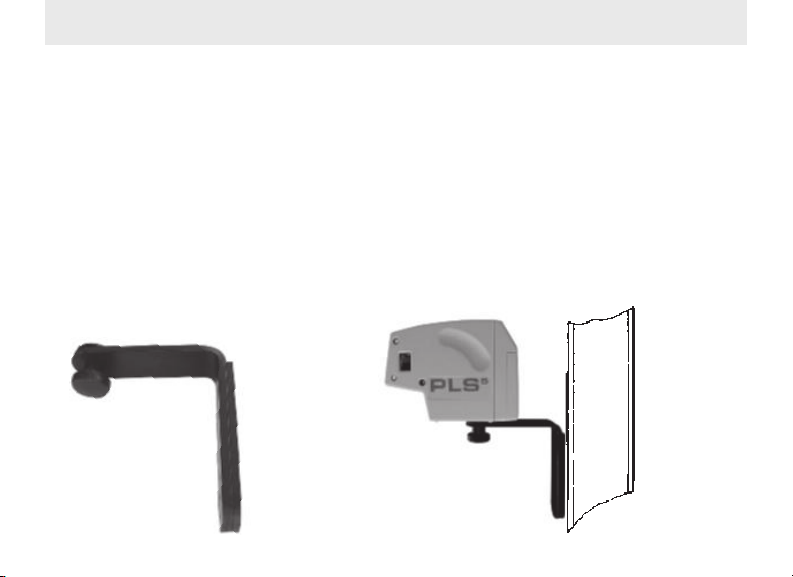
BANCO DE
ACERO
FIG. 11
FIG. 12
12
Page 34

Objetivo de Péndulo
Use el objetivo de péndulo de PLS5 para ahorrar tiempo en una amplia variedad de tareas de
alineación. Para escuadra: Para alcanzar una precisión coherente en establecer o verificar la
escuadra, use el objetivo del PLS5 para transferir el haz láser a la superficie del piso. Para
establecer escuadra, consulte la página 8 de este manual. Siempre monte el láser PLS5 en la
base del piso al establecer escuadra. El objeto de péndulo está diseñado de modo que
los haces se observen mejor a esta altura.
Para la transferencia de líneas verticales:
Para transferir marcas verticales de forma rápida y precisa a una pared:
1. Coloque la parte frontal del láser PLS5 contra la pared con el haz de
avance N.º 1 en la marca que desea transferir. (Si la marca está en el piso,
coloque el haz hacia abajo N.º 2 sobre la marca).
2. Coloque el objetivo con su parte plana posterior contra la pared a la altura
deseada y mueva el objetivo hasta que el haz hacia arriba N.º 3 esté en
el centro del objetivo alineado de plástico.
3.Marque la parte superior o inferior de las clavijas de flechas del objetivo.
OBJETIVO DE PÉNDULO
FIG. 13
13
Page 35
Sistema PLS5 Interior-Exterior
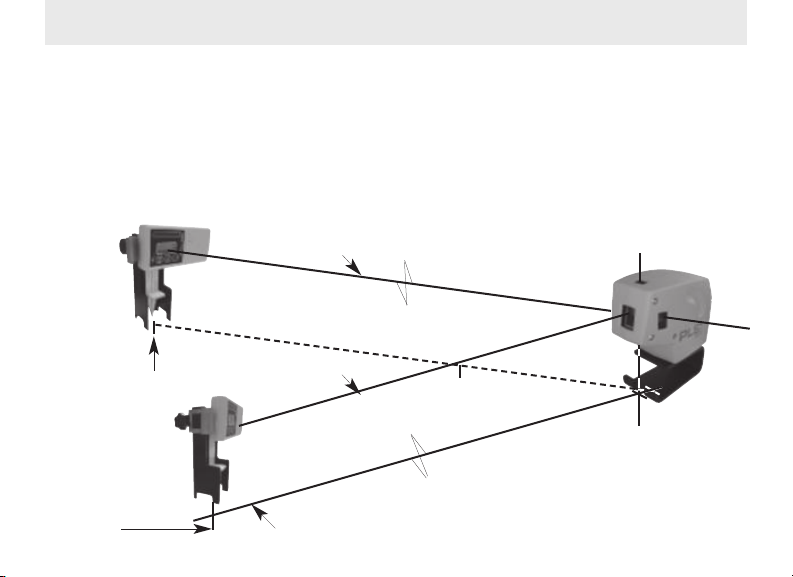
El PLS5 es la única herramienta de replanteo de punto a punto para usar en obras en
interiores y exteriores. La fuerte luz solar ha limitado tradicionalmente el uso de láseres
de haz visibles a proyectos en el interior. El PLS5 junto con nuestro receptor láser ofrece
al contratista la posibilidad de replantear con exactitud una obra de hasta más de 250
pies, incluso en las condiciones exteriores con más luz.
El PLS5 también puede usarse en el interior, sin el receptor, para todas las tareas
de alineación de punto a punto.
“Sonido
Sonido”
C
L
MARCA
“Sonido
Sonido”
C
L
MARCA
HAZ N.º 5
HAZ N.º 1
FIG. 7
LÍNEA DE REPLANTEO O REFERENCIA
14
Page 36
Aplicaciones en Exteriores del PLS5
CONSTRUCCIÓN DE HORMIGÓN
• Replanteo de camillas
• Replanteo y alineación para proyectos de mampostería
• Replanteo para cortes con sierras (juntas de control)
• Alineación de pernos de anclajes y pernos J
• Replanteo y alineación de muelles
y zapatas de columnas
• Replanteo de tablas de contorno para hormigón
pavimentos de hormigón
“Sonido Sonido”
“Sonido Sonido”
15
CONSTRUCCIÓN ELÉCTRICA Y MECÁNICA
• Instalación de conductos
• Instalación de tuberías de desechos y suministros
• Instalación de tuberías de suministro de gas natural
CONSTRUCCIÓN DE MARCOS
• Replanteo de líneas de control en hormigón cimientos,
plataformas y sobrepisos
• Alineación de marcos de acero de calibre pesado
en exteriores
• Replanteo y alineación para marcos de madera
comerciales y residenciales
CONSTRUCCIÓN DE VIDRIADOS
• Replanteo e instalación de fachadas de vidrio y
proyectos de escaparate
Page 37

Especificaciones
5
Fuente de la luz: Diodo láser semiconductor Diodo láser semiconductor
Rango de operación: +/- 30.5 m +/-30.5 m
Precisión: < 0.3 cm a 30.5 m < 0.6 cm a 30.5 m
Nivelación: Automática Automática
Rango de nivelación: +/- 6° +/- 6°
Alimentación: 3 pilas AA, alcalinas o 3 pilas AA, alcalinas o
Tiempo de funcionamiento: + 30 horas de uso continuo + 30 horas de uso continuo
Temperatura de funcionamiento: 0° F a 122° F 0° F a 122° F
Temperatura de almacenamiento: -40° F a 158° F -40° F a 158° F
Indicadores: Luz verde: ENCENDIDO Luz verde: ENCENDIDO
Ambiental: Resistente al agua, no Resistente al agua, no
Dimensiones: 5 cm x 10 cm x 12 cm 4.5 cm x 13 cm x 8 cm
Peso (con baterías): 1.13 libras (0.52 kg) 12 onzas (0.33 kg)
PLS
630-650nM, visible 630-650nM, visible
(<3 mm a 30 metros) (<6mm a 30 metros)
Recargable de Ni-Cad Recargable de Ni-Cad
(-18° C a 50° C) (-18° C a 50° C)
(-40° C a 70° C) (-40° C a 70° C)
Luz roja:EXCEDE Luz roja: EXCEDE
INCLINACIÓN INCLINACIÓN
Luz ámbar: BATERÍA Luz ámbar: BATERÍA
BAJA BAJA
sumergible sumergible
PLS
3
16
Page 38

Técnicos del laboratorio PLS
PLS • Pacific Laser Systems
2550 Kerner Blvd., San Rafael, CA 94901
www.plslaser.com o 800.601.4500
Page 39
NUEVO
PLS5
PACIFIC LASER
SYSTEMS
The Professional Standard
Manual de instrucciones
Page 40

ÍNDICE
Bienvenido a las herramientas láser PLS. Estamos convencidos de que ha elegido el
mejor instrumento láser del mundo. Apostamos por ofrecer el máximo nivel de calidad
en mano de obra y materiales.
Las herramientas láser PLS han sido desarrolladas por contratistas con el objetivo de
proporcionar la información de alineación más precisa y eficaz a todos los tipos de profesionales. Miles de clientes pueden dar fe del ahorro de tiempo y dinero que se
obtienen gracias al rendimiento, la comodidad y la versatilidad de las herramientas láser
de PLS. Puede tener la confianza de que, si fuera necesario, obtendrá rápidamente asistencia técnica sobre su equipo láser.
ÍNDICE
Introducción ..............................................1
Mantenimiento ..........................................2
Garantía.....................................................2
Características...........................................3
Etiquetado e instrucciones de seguridad.. 4
Haces........................................................ 5
Plomada....................................................6
Nivel.......................................................7
Escuadra............................................... 8
Comprobación de calibración.... 9, 10, 11
Soporte magnético...............................12
Objetivo................................................13
PLS 5 sistema exterior...................14, 15
Especificaciones de PLS5 y PLS3...... 16
1
Page 41

ANTENIMIENTO
M
El cuidado necesario de los equipos PLS3 y PLS5 es sobre todo una cuestión de sentido común. Retire
las pilas de la unidad si el láser va a estar almacenado durante un período considerable. Mantenga
limpias las ventanas ópticas con un trapo suave o toallitas de limpieza de lentes fotográficas. Evite condiciones de almacenamiento en un ambiente caliente o frío durante demasiado tiempo.
G
ARANTÍA
PLSoPacific Laser Systems garantiza al comprador original que este producto no tendrá defectos materiales o de mano de obra en circunstancias de uso normal durante un período de dos años a partir de la
fecha de compra. Durante el período de garantía, y presentando prueba de compra, el producto será
reparado o reemplazado (por un modelo igual o similar a nuestra discreción), sin cargo por repuestos ni
mano de obra a través de PLS. El comprador se hará cargo de todos los costes de envío, embalaje y
seguro. Una vez completada la reparación o el reemplazo, la unidad será devuelta al cliente, con costes
de envío previamente pagados. La garantía no se aplicará al producto si ha sido utilizado indebidamente,
maltratado o alterado. Además, el derrame de la pila, las mellas o abolladuras en la cubierta plástica, la
rotura de las ventanas ópticas, los daños al interruptor o la membrana del indicador luminoso se consideran consecuencia del mal uso o maltrato. La alteración o la retirada de las etiquetas de precaución o de
certificación invalidarán esta garantía.
Ni esta garantía, ni ninguna otra, expresa o implícita, incluidas las garantías implícitas de comerciabilidad,
se extenderá más allá del período estipulado. No se asume ninguna responsabilidad por daños imprevistos o consecuentes. Esta garantía le otorga derechos legales específicos y usted podría tener otros
derechos que varían según el estado.
No está previsto que el propietario pueda realizar ninguna operación de mantenimiento ni reparación de
las herramientas PLS. Póngase en contacto con PLS o con el centro de servicio técnico de su zona si se
precisan reparaciones.
2
Page 42
C
ARACTERÍSTICAS
SOPORTE ACCESORIO DE DE 1/4 X 20 EN LA BASE DE CADA UNIDAD
PUERTA DE ACCESO A LAS PILAS
USE 3 PILAS ALCALINAS AA DE 1,5
V O PILAS DE NÍQUEL-CADMIO
3
VENTANAS ÓPTICAS
(5)
INDICADOR LED
ENCENDIDO: VERDE
ON
INCLINACIÓN: ROJO
OFF
BATERÍA BAJA: ÁMBAR
ENCENDIDO/APAGADO
VENTANAS ÓPTICAS
(3)
Page 43
E
TIQUETADO E INSTRUCCIONES DE SEGURIDAD
LATERAL DEL EQUIPO PLS5
PARTE TRASERA DEL EQUIPO PLS5
REGISTRADO EN LA OFICINA DE
PATENTES DE LOS EE.UU.
PARTE SUPERIOR DEL EQUIPO PLS3
PRECAUCIÓN
RADIACIÓN LÁSER
NO MIRE DIRECTAMENTE AL HAZ DE LUZ NI
CON AYUDA DE INSTRUMENTOS ÓPTICOS
ETIQUETA DE APERTURA
ETIQUETA DE CERTIFICACIÓN
CON NÚM. DE ID.
EVITE LA EXPOSICIÓN
EMISIÓN DE
RADIACIÓN LÁSER
DESDE ESTA APERTURA
Los equipos PLS5 y PLS3
cumplen con los requisitos de
rendimiento de la FDA (EE.UU.),
21 CFR (Código de reglamentos
federales), subcapítulo J.
GLOBALLY SOURCED. FINALASSEMBLY IN U.S.A.
PATENT #6,938,360 1-800-601-4600
PLS 2550 KERNER BLVD., SAN RAFAEL, CA 94901
S/N:
CLASS 2 LASER PRODUCT
PLS5COMPLIES WITH FDA STDS. 21. CFR.,
CHAP. J 1040.10 & 11 EXCEPT FOR DEVIATION
PURSUANT TO LASER NOTICE .60 OF 7/26/2006
REGISTERED U.S. PATENT OFFICE.
DATE:
Los equipos PLS5 y PLS3 contienen un diodo láser semiconductor
con una longitud de onda de 635 nanómetros. La salida continuada de
cualquiera de los haces no debe superar nunca 1,0 milivatios. No mire
POTENCIA MÁX. DE EMISIÓN <1MW
LONGITUD DE ONDA 635-670NM
PRODUCTO LÁSER DE CLASE II
ETIQUETA DE CERTIFICACIÓN
GLOBALLY SOURCED. FINALASSEMBLY IN U.S.A.
PATENT #6,938,360 1-800-601-4600
PLS 2550 KERNER BLVD., SAN RAFAEL, CA 94901
S/N:
CLASS 2 LASER PRODUCT
PLS3COMPLIES WITH FDA STDS. 21. CFR.,
CHAP. J 1040.10 & 11 EXCEPT FOR DEVIATION
PURSUANT TO LASER NOTICE .60 OF 7/26/2006
CON NÚM. DE ID.
DATE:
nunca el haz láser directamente ni con instrumentos ópticos. Apague el equipo láser cuando no lo utilice.
PRECAUCIÓN: EL USO DE CONTROLES, AJUSTES O PROCEDIMIENTOS DIFERENTES A LOS ESPECIFICADOS EN ESTE DOCUMENTO PUEDE SUPONER UNA EXPOSICIÓN PELIGROSA A LA RADIACIÓN.
Estas etiquetas se encuentran en todos los equipos láser PLS. No se deben quitar ni desfigurar.
4
Page 44
#3
HACES
#5
#1
PLS
#2
5
Los cinco haces del equipo PLS5 son los siguientes: 1 Haz hacia adelante, 2 haz hacia
#4
#3
#1
#2
abajo, 3 haz hacia arriba, 4 haz hacia la izquierda, 5 haz hacia la derecha. Todos los haces del
equipo PLS5 presentan el mismo brillo y están dispuestos perpendicularmente entre sí.
3
PLS
Los tres haces del equipo PLS3 son los siguientes: 1 Haz hacia adelante, 2 haz hacia
abajo, 3 haz hacia arriba.
5
Page 45
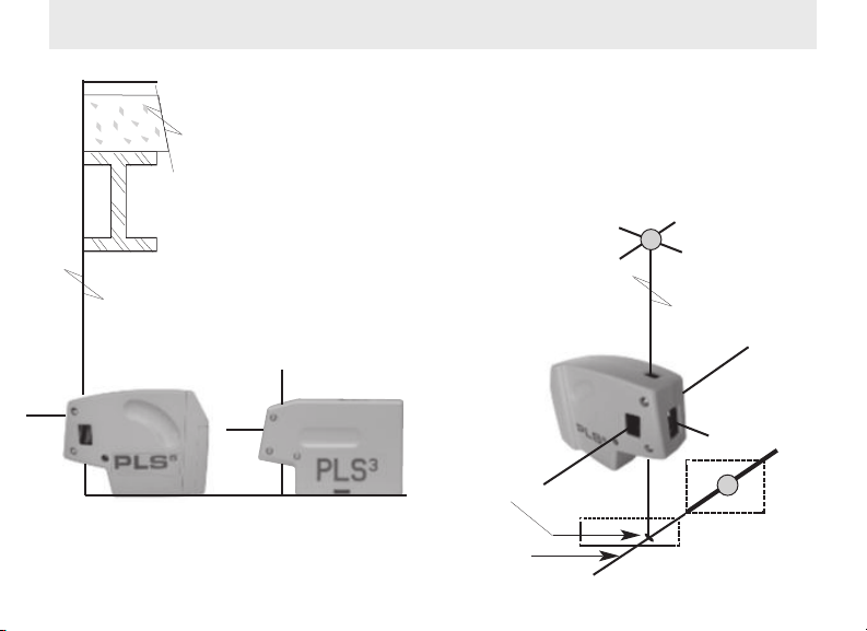
FIG. 2
P
LOMADA
Para establecer la plomada con los equipos PLS5 y PLS3, coloque el haz número 2 (hacia
abajo) sobre la marca que se debe transponer. Véase la figura 1. El haz número 3 (hacia arriba) queda exactamente aplomado dentro de los límites especificados. Puede colocar
marcas de plomada abajo y arriba, o bien en voladizo sobre el extremo del edificio, abertura
de pozo o chimenea, sobre el suelo, etc. Véase la figura 2. Utilice el soporte de pie con el
equipo PLS5 o PLS3 si desea aumentar el ángulo de visión del haz número 2 (hacia abajo).
Los equipos PLS3 y PLS5 pueden evaluar rápidamente las condiciones existentes para la
plomada. Utilice una cinta y el haz número 3 (hacia arriba).
Sitúe el láser junto a la estructura. Compruebe las distancias hacia
arriba y hacia abajo de la estructura. También se puede realizar
la transposición de marcas desde un tejado o desde un techo
hasta el suelo. Mueva el láser hasta que el haz número 3 (hacia
arriba) alcance el borde o el centro del componente del techo
que se desea transponer. Marque el suelo en el lugar del haz
número 2 (hacia abajo). Véanse las figuras 2 y 3
.
#3
FIG. 1
PUNTO DE
PLOMADA
#2
CENTRE EL
DISPOSICIÓN DEL SUELO
HAZ EN LA
DISPOSICIÓN
6
Page 46
N
IVEL
Para establecer la plomada con los equipos PLS5 y PLS3, coloque el haz número 2 (hacia abajo) sobre la
marca que se debe transponer. Véase la figura 1. El haz número 3 (hacia arriba) queda exactamente aplomado dentro de los límites especificados. Puede colocar marcas de plomada abajo y arriba, o bien en
TAPE
voladizo sobre el extremo del edificio, abertura de pozo o chimenea, sobre el suelo, etc. Véase la figura 2.
TAPE
6 M
3 M
Utilice el soporte de pie con el equipo PLS5 o PLS3 si desea aumentar
el ángulo de visión del haz número 2 (hacia abajo).
Los equipos PLS3 y PLS5 pueden evaluar rápidamente las condiciones
TAPE
FIG.6
existentes para la plomada. Utilice una cinta
y el haz número 3 (hacia arriba). Sitúe el
láser junto a la estructura. Compruebe las
distancias hacia arriba y hacia abajo de la
estructura. También se puede realizar la
transposición de marcas desde un tejado o
desde un techo hasta el suelo. Mueva el
láser hasta que el haz número 3 (hacia arriba) alcance el borde o el centro del componente del techo que se desea transponer.
Marque el suelo en el lugar del haz número
2 (hacia abajo). Véanse las figuras 2 y 3.
MARCA
MARCA
FIG. 4
FIG. 5
7
Page 47
E
SCUADRA
Para establecer una escuadra (ángulo recto), coloque el equipo PLS5 con el haz número 2 (hacia
abajo) sobre la línea de referencia de la disposición. Véase la figura 7. Coloque el objetivo del péndulo en esa línea y centre el haz número 1 (hacia delante) en el centro del objetivo. Una vez centrado, mueva el objetivo del péndulo hacia la escuadra en el haz número 4 (hacia la izquierda) o
número 5 (hacia la derecha). Haga una marca en el suelo o en una superficie junto al láser y una
segunda marca a la distancia deseada desde el láser. Véase la figura 7.
HAZ 5
C
L
MARCA
C
L
MARCA
HAZ 1
FIG. 7
LÍNEA DE REFERENCIA O DISPOSICIÓN
8
Page 48
V
ERIFICACIÓN DE LA CALIBRACIÓN
Existen varios métodos sencillos para comprobar la calibración y la precisión de los equipos
PLS5 y PLS3. Recomendamos que se realice periódicamente esta comprobación.
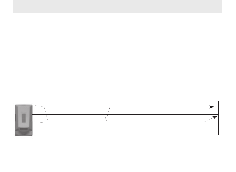
MÉTODO 1 (sólo PLS5): Comprobación rápida de precisión en el funcionamiento. Coloque el
equipo PLS5 en una superficie estable a unos 7,6 metros o más de una pared o un objetivo adecuado al efecto. Véase la figura 8. Oriente el haz número 1 (hacia delante) en dirección de la
pared o del objetivo y marque con cuidado el centro de elevación. Haga girar el equipo PLS5 90°
sobre su centro hasta que el haz número 5 (hacia la derecha) quede por encima de la primera
marca. Compruebe si hay diferencias en la elevación desde el centro del haz número 1 (hacia
delante) y el del número 5 (hacia la derecha). Repita la operación para comprobar el haz número
4. A unos quince metros, la diferencia no debería superar los 3 mm. A unos siete metros, la
diferencia no debería superar los 1,5 mm
PARED U OBJETIVO
MARCA
FIG. 8
9
Page 49
V
ERIFICACIÓN DE LA CALIBRACIÓN
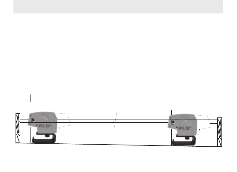
MÉTODO 2 (tanto PLS5 como PLS3): Comprobación exacta de la precisión del nivel. Busque una
línea en un lugar nivelado (preferiblemente, una losa de hormigón), de unos 7,5 metros o más, con
dos paredes opuestas. También puede utilizar listones de 2 x 4 para los objetivos. Véase la figura 9.
Coloque el láser a unos 15 cm del objetivo 1 y marque con cuidado la elevación del haz número 1
(hacia delante) sobre el objetivo. Gire el equipo láser 180° sobre su centro. Marque el centro de elevación del haz número 1 (hacia delante) sobre el objetivo 2. Desplace el láser hasta el objetivo 2. A
unos 15 cm del objetivo, marque el centro de elevación del haz número 1 (hacia delante) sobre el
objetivo 2. Gire el equipo láser sobre su centro y marque el centro de elevación en el objetivo 1.
Ahora tiene dos centros de elevación en cada objetivo. Con cuidado, mida la distancia entre los centros de cada conjunto de marcas. Si la distancia es la misma, significa que el láser está nivelado
con exactitud. Si hay una diferencia, reste una medición de la otra. Con este método se incrementa
la magnitud del error por un factor de dos. Así pues, divida esta diferencia por dos para detectar el
error de nivel de forma exacta. El error máximo para el equipo PLS5 es de 0,5 mm a 7,5 m, o 3,17
mm a 15 m. El error máximo para el equipo PLS3 es de 3,17 mm a 7,5 m, o 6,35 mm a 15 m.
OBJETIVO 1
FIG. 9
OBJETIVO 2
10
Page 50
V
ERIFICACIÓN DE LA CALIBRACIÓN
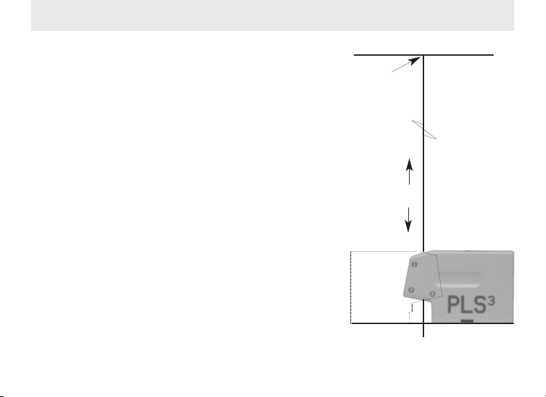
MÉTODO 3 (tanto PLS5 como PLS3): Comprobación
exacta de la precisión de la plomada. Para esta operación
se precisa una altura vertical considerable (más de 3 metros) y la posibilidad de realizar marcas a esa altura.
Coloque el equipo con el haz número 2 (hacia abajo) centrado con exactitud en ambos ejes sobre una marca en
forma de cruz. Véase la figura 10. En la superficie de arriba, marque los dos ejes del haz número 3 (hacia arriba).
Gire el láser 180° y coloque el haz número 2 (hacia abajo)
centrado con exactitud en la misma marca. El haz
número 3 (hacia arriba) debe encontrarse exactamente
sobre la primera marca.
MARCA
DISTANCIA
Si existe alguna diferencia entre las marcas 1 y 2, el error
del haz de plomada será la mitad de esa diferencia
11
FIG. 10
Page 51
I
NSTRUCCIONES SOBRE EL SOPORTE MAGNÉTICO
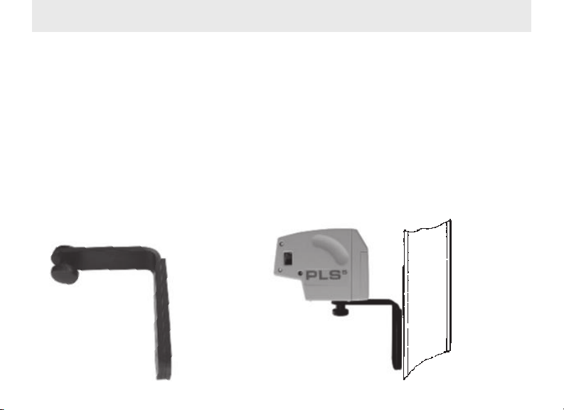
Para utilizar el soporte magnético con el láser PLS:
1. Atornille el botón roscado de 1/4 x 20 al soporte de la base del láser PLS.
2. Monte el láser PLS y el soporte con los vástagos de acero, el bastidor de la compuerta de
acero, los equipos de haces, la escuadra, etc.
3. Gire el láser PLS hasta el punto deseado y haga la marca.
Combine el láser PLS, el soporte magnético, una escuadra de marco de acero estándar y una o
más mordazas para poder colocar el láser en la posición deseada. Puede fijar la escuadra en
bloques de hormigón, escaleras, vigas de madera, etc. Acople el láser PLS con el soporte magnético según lo descrito anteriormente. Si taladra dos orificios pequeños centrados en la sección
larga de la escuadra, podrá acoplarla a divisiones de mampostería sin terminar con tornillos o
clavos desechables. Deslice el láser PLS arriba y abajo sobre la escuadra montada, exactamente
hasta la altura deseada.
VÁSTAGO
DE ACERO
FIG. 11
FIG. 12
12
Page 52

O
BJETIVO DEL PÉNDULO
El objetivo del péndulo de la unidad PLS5 puede servirle para diferentes tareas de alineación y le
permitirá ahorrar mucho tiempo. Para establecer un ángulo recto: A fin de lograr una precisión
sistemática a la hora de establecer o comprobar un ángulo recto, el objetivo del equipo PLS5 se
puede utilizar para transferir el haz de láser a la superficie del suelo. Si desea establecer un
ángulo recto, consulte la página 8 de este manual. Monte siempre el equipo láser PLS5 sobre el
soporte de suelo cuando se disponga a establecer un ángulo recto. El objetivo del péndulo está
diseñado de manera que los haces se vean mejor a esta altura.
Para la transferencia de líneas verticales:
Para transferir a una pared marcas verticales de un modo rápido y preciso:
1.Sitúe la parte delantera del equipo láser PLS5 contra la pared con el haz
número 1 (hacia delante) sobre la marca que se debe transferir.
(Si la marca está en el suelo, coloque el haz número 2 (hacia abajo) sobre
la marca).
2.Coloque el objetivo con la parte trasera (plana) contra la pared, a la altura
deseada, y desplace el objetivo hasta que el haz número 3 (hacia arriba)
quede centrado en el objetivo recubierto de plástico.
3.Marque la parte superior o inferior de los pasadores de flecha del objetivo.
OBJETIVO DEL PÉNDULO
FIG. 13
13
Page 53
S
ISTEMA PLS5 INTERIOR-EXTERIOR
El equipo PLS5 es la única herramienta de disposición punto a punto para el uso tanto
en interiores como en exteriores. Tradicionalmente, la luz solar ha limitado el uso de los
haces láser visibles en los proyectos de interiores. El PLS5, junto con nuestro receptor
láser, brinda al contratista la posibilidad de diseñar con precisión un espacio de trabajo
de más de 76 metros, incluso en los días en que la luz del sol es más intensa.
El equipo PLS5 también se puede utilizar en interiores, sin el receptor, para todas las
tareas de alineación punto a punto.
“Bip
Bip”
C
L
MARCA
“Bip
Bip”
C
L
MARCA
HAZ 5
HAZ 1
LÍNEA DE REFERENCIA O DISPOSICIÓN
FIG. 7
14
Page 54
A
PLICACIONES DEL EQUIPO PLS5 EN EXTERIORES
CONSTRUCCIONES DE HORMIGÓN
• Disposición de camillas de replanteo
• Disposición y alineación en proyectos de
albañilería
• Disposición de cortes de sierra
(uniones de control)
• Alineación de anclajes y pernos en J
• Disposición y alineación de pilares y
cimientos
• Disposición de placas para superficies de
hormigón
“Bip bip”
“Bip bip”
15
CONSTRUCCIÓN MECÁNICA Y ELÉCTRICA
• Canalizaciones para conductos
• Canalizaciones para tubos de desagüe
y suministro
• Canalizaciones para tubos de suministro
de gas natural
CONSTRUCCIÓN DE ESTRUCTURAS
• Disposición de líneas de control en placas
de hormigón, plataformas y subsuelos
• Alineación de estructuras exteriores de
tubo de acero pesado
• Disposición y alineación para marcos de
madera en aplicaciones comerciales y
residenciales
CONSTRUCCIÓN PARA ACRISTALAMIENTO
• Disposición e instalación de cierres de
revestimiento y escaparates.
Page 55

E
SPECIFICACIONES
PLS
5
PLS
3
Fuente de luz: Diodo láser semiconductor Diodo láser semiconductor
630-650 nm, visible 630-650 nm, visible
Márgenes operativos: +/- 30 metros +/- 30 metros
Precisión: < 1/8 de pulgada a 100 pies < _ de pulgada a 100 pies
(< 3 mm a 30 metros) (< 6 mm a 30 metros)
Nivelación: Automática Automática
Márgenes de nivelación: +/- 6° +/- 6°
Alimentación eléctrica: 3 pilas AA, alcalinas o 3 pilas AA, alcalinas o
recargables de níquel-cadmio recargables de níquel-cadmio
Tiempo de funcionamiento: > 30 horas de uso continuo > 30 horas de uso continuo
Temp. de funcionamiento: De 0 °F a 122 °F De 0 °F a 122 °F
(de -18 °C a 50 °C) (de -18 °C a 50 °C)
Temp. de almacenamiento: De -40 °F a 158 °F De -40 °F a 158 °F
De (-40 °C a 70 °C) De (-40 °C a 70 °C)
Indicadores: Luz verde: Encendido Luz verde: Encendido
Luz roja:
EXCESO INCLINACIÓN Luz roja: EXCESO INCLINACIÓN
Luz ámbar: BATERÍA Luz ámbar: BATERÍA
BAJA BAJA
Especificaciones ambientales:Resistente al agua, no Resistente al agua, no
sumergible sumergible
Dimensiones:
5,08 cm x 10,16 cm x 12,06 cm 4,44 cm x 12,7cm x 9,5 cm
Peso (con pilas): 1,13 lb (0,52 kg) 12 onzas (0,33 kg)
16
Page 56

Técnicos del laboratorio PLS
PLSoPacific Laser Systems
2550 Kerner Blvd., San Rafael, CA 94901 (EE.UU.)
www.plslaser.com o 800 601 4500
Page 57
NUOVO
PLS5
PACIFIC LASER
SYSTEMS
The Professional Standard
Manuale d'uso
Page 58

Indice
PLS laser tools vi dà il benvenuto. Complimenti per aver scelto il migliore strumento laser
del mondo. Ci dedichiamo ai migliori standard di qualità in materiali e manodopera.
PLS laser tools è stata sviluppata dai contraenti per offrire a qualsiasi azienda informazioni di allineamento precise e affidabili. Migliaia di clienti possono confermare il
risparmio di tempo e denaro ottenuto grazie alle prestazioni, alla convenienza e alla versatilità degli strumenti laser PLS. Potrete contare su un servizio rapido, nel caso fosse
necessario.
INDICE
Introduzione.....................................1
Manutenzione..................................2
Garanzia..........................................2
Caratteristiche.................................3
Etichette di sicurezza e istruzioni....4
Fasci................................................5
Filo a piombo...................................6
Livellamento............................................7
Squadro...................................................8
Controllo calibratura.......................9,10.11
Supporto magnetico...............................12
Traguardo...............................................13
PLS5 sistema per esterno.................14,15
Caratteristiche tecniche PLS5 e PLS3...16
1
Page 59

Manutenzione
Una buona cura degli strumenti PLS3 e PLS5 è essenzialmente retta dal buonsenso. Rimuovere
le batterie dall'apparecchio se il laser deve essere conservato per un periodo di tempo prolungato.
Mantenere le finestre ottiche pulite usando un panno morbido o un tessuto per la pulizia degli obiettivi fotografici. Evitare condizioni di conservazione con calore o freddo prolungati.
Garanzia
PLS Pacific Laser Systems garantisce all'acquirente originale che questo prodotto è privo di difetti
di materiale o fabbricazione in normali condizioni di uso per un periodo di due anni a scadere dalla
data di acquisto. Durante tale periodo, e soggetto a presentazione della ricevuta di acquisto, il
prodotto verrà riparato o sostituito da PLS (con uno uguale o simile a nostra scelta), senza spese
a carico del cliente per ricambi o manodopera. L'acquirente sosterrà tutti i costi di spedizione, imballaggio e assicurazione. Al termine della riparazione o sostituzione, l'unità verrà inviata al cliente con
trasporto prepagato. La garanzia non si applica ai prodotti usati in modo improprio, danneggiati o
modificati. Senza limitazioni a quanto detto sopra, le batterie scariche, le ammaccature o intaccature del contenitore in plastica, la rottura delle finestre ottiche, i danni alla membrana
interruttore/led, sono considerati come provocati da un uso improprio o maltrattamento. La
manomissione o rimozione delle etichette di attenzione e certificazione annullano la garanzia.
Né la presente garanzia né altre garanzie qualsiasi, esplicite o implicite, compreso le garanzie
implicite di commerciabilità, si estenderanno oltre il periodo della garanzia. Non si assume nessuna
responsabilità per danni incidentali o indiretti. La presente garanzia riconosce al cliente i diritti legali
specifici; egli, inoltre, potrà godere anche di altri diritti, variabili da stato a stato.
L'utente non può fare nulla in termini di servizio o manutenzione sugli attrezzi PLS. Per riparazione,
contattare PLS o il locale centro di assistenza.
2
Page 60
Caratteristiche
SUPPORTO ACCESSORI 1/4 X 20 ALLA BASE DI TUTTE LE UNITÀ
COPERCHIO
DELLA BATTERIA
USARE TRE BATTERIE
AA DA 1,5 V O AL NICAD
3
FINESTRE OTTICHE
(5)
INDICATORE A LED
ACCESO: VERDE
ON
INCLINAZIONE: ROSSO
OFF
BATTERIA SCARICA: AMBRA
ACCENSIONE/SPEG
NIMENTO
FINESTRE OTTICHE
(3)
Page 61
Etichette di sicurezza e istruzioni
LATO PLS5
RETRO PLS5
UFFICIO BREVETTI REGISTRATI USA.
LATO SUPERIORE PLS3
A TTENZIONE
RADIAZIONE LASER
NON GUARDARE DIRETTAMENTE IL
RAGGIO NÉ GUARDARE DIRETTAMENTE
ETICHETTA DI CERTIFICAZIONEDI
ETICHETTA DELL'APERTURA
EVITARE DI ESPORSI ALLA
RADIAZIONE LASER
EMESSA ATTRAVERSO QUESTA
APERTURA
PLS5 e PLS3 sono conformi agli
standard USA FDA, 21 CFR,
Subchapter J.
I laser PLS5 e PLS3 contengono
un diodo laser a semiconduttore
RICONOSCIMENTO
GLOBALLY SOURCED. FINALASSEMBLY IN U.S.A.
PATENT #6,938,360 1-800-601-4600
PLS 2550 KERNER BLVD., SAN RAFAEL, CA 94901
S/N:
CLASS 2 LASER PRODUCT
PLS5COMPLIES WITH FDA STDS. 21. CFR.,
CHAP. J 1040.10 & 11 EXCEPT FOR DEVIATION
PURSUANT TO LASER NOTICE .60 OF 7/26/2006
REGISTERED U.S. PATENT OFFICE.
DATE:
con lunghezza d'onda di 635 nanometri.
L'emissione continua di un singolo fascio non supera 1,0 mW.
NON FISSARE IL RAGGIO O GUARDARLO DIRETTAMENTE CON
CON STRUMENTI OTTICI
POTENZA MAX USCITA <1MW
LUNGHEZZA D'ONDA 635-670NM
PRODOTTO LASER CLASSE II
ETICHETTA DI CERTIFICAZIONE DI
GLOBALLY SOURCED. FINALASSEMBLY IN U.S.A.
PATENT #6,938,360 1-800-601-4600
PLS 2550 KERNER BLVD., SAN RAFAEL, CA 94901
S/N:
CLASS 2 LASER PRODUCT
PLS3COMPLIES WITH FDA STDS. 21. CFR.,
CHAP. J 1040.10 & 11 EXCEPT FOR DEVIATION
PURSUANT TO LASER NOTICE .60 OF 7/26/2006
RICONOSCIMENTO
DATE:
STRUMENTI OTTICI. Spegnere il laser se non è in uso.
ATTENZIONE: L'USO DI CONTROLLI, REGOLAZIONI O PROCEDURE DIVERSE DA QUELLE SPECIFICATE
NEL PRESENTE DOCUMENTO POSSONO CAUSARE L'ESPOSIZIONE A RADIAZIONI PERICOLOSE.
Queste etichette sono affisse su tutti i laser PLS. Non devono essere rimosse o rese illeggibili.
4
Page 62
#3
Raggi
#5
#1
#2
5
PLS
I cinque raggi del PLS5 sono: n. 1 Raggio in avanti, n. 2 Raggio in basso, n. 3 Raggio in
#4
#3
#1
#2
alto, n. 4 Raggio a sinistra, n. 5 Raggio a destra. Tutti i raggi del PLS5 presentano la stessa intensità luminosa e sono reciprocamente in squadro.
3
PLS
I tre raggi del PLS3 sono: n. 1 Raggio in avanti, n. 2 Raggio in basso, n. 3 Raggio in alto.
5
Page 63
Filo a piombo
Per stabilire il filo a piombo con il PLS5 e PLS3, posizionare il raggio n. 2 sul contrassegno
da riportare. Vedere la figura 1. Il raggio n. 3 sarà esattamente a piombo entro le specifiche.
È possibile tracciare la linea a piombo in basso e in alto, oppure a sbalzo rispetto al bordo
di un'apertura di una costruzione o di un albero, di un piano, ecc., v. figura 2. Usare il supporto a pavimento con il PLS5 o PLS3 per aumentare l'angolo di visuale del raggio n. 2.
Il PLS3 e PLS5 sono in grado di recuperare rapidamente le condizioni di filo a piombo
esistenti. Usare un nastro e il raggio n. 3 verso l'alto. Posizionare il laser vicino alla struttura.
Controllare le distanze in alto e in basso alla struttura.
È anche possibile riportare le marcature da un tetto o un
soffitto fino al pavimento. Spostare il laser fino a che il raggio
n. 3 colpisca il bordo o il centro del componente a soffitto da
riportare. Marcare il pavimento in corrispondenza del raggio n.
2. Vedere le figure 2 e 3.
#3
FIG. 2
FIG. 3
FILO A
PIOMBO
DISEGNO DEL PAVIMENTO
FIG. 1
#2
RAGGIO
CENTRATO SUL
DISEGNO
6
Page 64
Livello
È facile determinare e contrassegnare con precisione il livello con i modelli PLS5 e PLS3. Ruotare
lo strumento sul proprio centro, arrestare per contrassegnare il livello o i punti di livello. Vedere la
figura 4. È possibile usare qualsiasi superficie stabile. Con lo strumento montato su un treppiede
TAPE
20’
TAPE
10’
o su supporto a parete, ruotare e marcare. Vedere la figura 5.
Quando si ruota il PLS5 o PLS3 su un treppiede, assicurarsi che
la testina del supporto sia perfettamente livellata. Eventuali
TAPE
errori nella marcatura comportano l'errato allineamento del treppiede.
Per recuperare le condizioni di livello
esistenti, puntare nella direzione per
recuperare. Usando un nastro o una
barra con un riferimento, è possibile
annotare rapidamente le variazioni nel livello a diverse distanze.Vedere la figura 6.
FIG.6
CONTRASSEGNO
CONTRASSEGNO
FIG. 4
FIG. 5
7
Page 65
Squadro
Per stabilire lo squadro, posizionare il PLS5 con il raggio n. 2 sulla linea di riferimento. Vedere la
figura 7. Posizionare il traguardo pendente sulla linea di riferimento e centrare il raggio n. 1 sul centro del traguardo. Una volta centrato, spostare il traguardo sospeso per eseguire lo squadro con il
raggio n. 4 o n. 5. Contrassegnare il pavimento o la superficie vicino al laser e un secondo contrassegno alla distanza desiderata dal laser.Vedere la figura 7.
RAGGIO N. 5
C
L
CONTRASSEGNO
RAGGIO N. 1
FIG. 7
C
L
CONTRASSEGNO
SCHEMA DELLA LINEA DI RIFERIMENTO
8
Page 66
Controllo della calibratura
Esistono diversi semplici modi per controllare la calibratura e la precisione del PLS5 e PLS3.
Si raccomanda di effettuare un controllo periodico.
Metodo 1 (solo per PLS5) Controllo rapido della precisione delle prestazioni. Posizionare il PLS5
su una superficie stabile 25'-0" o più da una parete adatta o da un traguardo. Vedere la fig. 8.
Puntare il raggio n. 1 sulla parete o sul traguardo e contrassegnare con cura il centro dell'elevazione. Ruotare di 90° il PLS5 sul proprio asse fino a che il raggio n. 5 si porta sul primo contrassegno. Controllare se esiste differenza nell'elevazione tra il centro del raggio n. 1 e il centro del
raggio n. 5. Ripetere il controllo con il raggio n. 4. A 15 m (50'-0") la differenza non deve superare
3,2 mm (1/8"). A 7,6 m (25'-0") la differenza non deve superare 1,6 mm (1/16").
CONTRASSEGNO A PARETE O TRAGUARDO
CONTRASSEGNO
FIG. 8
9
Page 67
Controllo della calibratura
METODO 2 (per PLS5 e PLS3) Controllo esatto della precisione di livellamento. Trovare un tratto
abbastanza livellato (preferibilmente una pavimentazione in cemento) da circa 8 m (25') o maggiore con due pareti opposte. Si possono usare come traguardi dei travetti 2 x 4.Vedere la fig. 9.
Posizionare il laser a circa 15 cm (6") dal traguardo n. 1 e contrassegnare con cura l'elevazione
del raggio n. 1 sul traguardo. Ruotare il laser di 180° sul proprio asse. Contrassegnare il centro di
elevazione del raggio n. 1 sul traguardo n. 2. Spostare il laser sul traguardo n. 2. A 15 cm (6") dal
traguardo, contrassegnare il centro di elevazione del raggio n. 1 sul traguardo n. 2. Ruotare il laser
sul proprio asse e contrassegnare il centro di elevazione sul traguardo n. 1. A questo punto si
hanno due centri di elevazione per ogni traguardo. Misurare accuratamente la distanza tra i punti
di ciascuna coppia di marcature. Se la distanza risulta la stessa, il laser è livellato con precisione.
Se si riscontra una differenza, eseguire la sottrazione tra le due misure. Con questo metodo l'errore viene amplificato di un fattore di due. Per calcolare l'errore effettivo, dividere il risultato della
differenza per due. L'errore massimo ammesso per PLS5 è 1,6 mm (1/16") a 7,6 m (25'-0") o
TRAGUARDO N. 1
FIG. 9
TRAGUARDO N. 2
10
Page 68
Controllo della calibratura
METODO 3 (per PLS5 e PLS3) Controllo esatto della precisione del filo a piombo. Questo controllo richiede una
distanza verticale significativa, almeno 3 m (10'-0") e la
possibilità di contrassegnare a tale altezza. Posizionare lo
strumento con il raggio n. 2 esattamente centrato su
entrambi gli assi su una croce. Vedere la figura 10. Sulla
superficie sovrastante, contrassegnare entrambi gli assi
del raggio n. 3. Ruotare il laser di 180° e posizionare il
raggio n. 2 esattamente centrato sullo stesso contrassegno. Il raggio n. 3 dovrà essere esattamente sovrapposto al
primo contrassegno.
Se si riscontra una differenza tra il contrassegno n. 1 e n.
2, l'errore sul piombo è dato dalla metà del valore della
differenza.
11
CONTRASSEGNO
DISTANZA
FIG. 10
Page 69
Istruzioni per il supporto magnetico
Per utilizzare il supporto magnetico con il laser PLS:
1. Avvitare il pomello filettato 1/4 x 20 al supporto sulla base del laser PLS.
2. Fissare il laser PLS con il supporto ai perni di acciaio, ai telai in metallo delle porte, agli
squadri, ecc.
3. Ruotare il laser PLS al punto desiderato e tracciare il contrassegno.
Grazie alle combinazioni offerte dal laser unitamente al supporto magnetico, agli squadri standard
e a uno o più morsetti, si ha la possibilità di montare il laser in un numero illimitato di configurazioni. Bloccare uno squadro alle forme in cemento, alle scale, travi in legno, ecc. Fissare il laser
PLS con il supporto magnetico come descritto sopra. Se si preparano due piccoli fori centrati sulla
sezione lunga dello squadro, questo può essere fissato sui tramezzi in cartongesso ancora da
finire con viti o chiodi da rimuovere. Far scorrere il laser su e giù sullo squadro fino all'altezza
desiderata.
PERNI IN
ACCIAIO
FIG. 11
FIG. 12
12
Page 70

Traguardo a pendolo
Usare il traguardo a pendolo PLS5 per risparmiare tempo in molteplici compiti di allineamento.
Controllo di squadratura: Per un controllo preciso di squadratura, usare il traguardo PLS5 per
riportare il raggio laser sulla superficie del pavimento. Per determinare lo squadro, vedere pagina
8 del presente manuale. Montare sempre il laser PLS5 sul supporto a pavimento quando si stabilisce lo squadro. Il traguardo a pendolo è stato realizzato in modo tale che la visibilità dei raggi
sia ottimale a tale altezza.
Per riportare le linee verticali:
Per riportare i contrassegni rapidamente e con precisione su una parete:
1. Posizionare la parte anteriore del laser PLS5 contro la parete con il
raggio n. 1 sul contrassegno da riportare. (Se il contrassegno è sul
pavimento, posizionare il raggio n. 2 sul contrassegno)
2. Posizionare il traguardo con la parte piana posteriore contro la parete
all'altezza desiderata e spostare il traguardo fino a che il raggio n. 3 sia
centrato sul traguardo in plastica allineato.
3. Contrassegnare l'estremità superiore o inferiore delle frecce
del traguardo.
TRAGUARDO A PENDOLO
FIG. 13
13
Page 71
Sistema PLS5 per interni e per esterni
Il PLS5 è l'unico strumento puntatore per uso sia in cantieri all'aperto che al chiuso. Di
solito la luce del sole ha sempre limitato l'uso dei raggi laser visibili ai lavori all'interno. Il
PLS5 accoppiato con il ricevitore laser offre la capacità di tracciare con precisione un
cantiere fino a 76 m (250 piedi) anche in condizioni di massima illuminazione esterna.
Il PLS5 può essere usato anche all'interno, senza ricevitore, per tutti i compiti di allineamento.
“Beep
Beep”
C
L
CONTRASSEGNO
“Beep
Beep”
C
L
CONTRASSEGNO
RAGGIO N. 5
RAGGIO N. 1
FIG. 7
SCHEMA DELLA LINEA DI RIFERIMENTO
14
Page 72
Applicazioni esterne del PLS5
COSTRUZIONI IN CEMENTO
• Tracciamento delle tavole guida
• Tracciamento e allineamento per progetti di
muratura
• Tracciamento per taglio (giunti di controllo)
• Allineamento di punti di ancoraggio e bulloni a J
• Tracciamento e allineamento di pilastri e plinti
• Tracciamento delle casseforme cemento
“Beep Beep”
“Beep Beep”
15
COSTRUZIONI ELETTRICHE E MECCANICHE
• Tracciamento dei condotti
• Tracciamento delle linee di alimentazione
e scarico
• Tracciamento delle linee di alimentazione
del gas naturale
COSTRUZIONI SU TELAIO
• Tracciamento delle linee di controllo su
pavimentazione in calcestruzzo, rivestimenti
e sotto-pavimenti
• Allineamento di strutture in acciaio
pesante esterne
• Tracciamento e allineamento per strutture
in legno commerciali e residenziali
COSTRUZIONI DI VETRATE
• Tracciamento e installazione per progetti
di murata in vetro esterna e vetrine.
Page 73

Caratteristiche tecniche
PLS
5
PLS
3
Sorgente luminosa: diodo laser a semiconduttori diodo laser a semiconduttori
630-650 nm, visibile 630-650 nm, visibile
Raggio d'azione: +/- 30 m +/- 30 m
Precisione: < 1/8" @ 100 piedi < 1/4" @ 100 piedi
(< 3 mm a 30 m) (< 6 mm a 30 m)
Livello: Automatico Automatico
Campo di livellazione: +/- 6° +/- 6°
Alimentazione: 3 batterie AA alcaline o 3 batterie AA alcaline o
ricaricabili al Ni-Cad ricaricabili al Ni-Cad
Durata di funzionamento: 30 ore di uso continuo 30 ore di uso continuo
Temperatura di esercizio: da 0 °F a 122 °F da 0 °F a 122 °F
(da -18 °C a 50 °C) (da -18 °C a 50 °C)
Temperatura di conservazione: da -40 °F a 158 °F da -40 °F a 158 °F
(da -40 °C a 70 °C) (da -40 °C a 70 °C)
Indicatori: Luce verde: ON (ACCESO) Luce verde: ON (ACCESO)
Luce rossa: INCLINAZIONE ECCESSIVA Luce rossa: INCLINAZIONE ECCESSIVA
Luce color ambra: BATTERIA SCARICA Luce color ambra: BATTERIA SCARICA
Specifiche ambientali: Resistente all'acqua; non immergibile Resistente all'acqua; non immergibile
Dimensioni: 50 x 100 x 120 mm 45 x 127 x 95 mm
Peso (incluse batterie): 1,13 lb (0,512 kg) 12 oz (0,340 kg)
16
Page 74

PLS Lab Technicians
PLS•Pacific Laser Systems
2550 Kerner Blvd., San Rafael, CA 94901
www.plslaser.com o 800 601 4500 (numero verde USA)
Page 75
NEUES
MODELL
PLS5
PACIFIC LASER
SYSTEMS
The Professional Standard
Bedienungsanleitung
Page 76

Inhaltsverzeichnis
Willkommen bei PLS-Laserwerkzeugen. Wir sind fest davon überzeugt, dass Sie das
beste Laserwerkzeug der Welt gewählt haben. Wir verpflichten uns zu höchsten
Qualitätsstandards sowohl beim verwendeten Material als auch in der Herstellung.
PLS-Laserwerkzeuge wurden von Bauunternehmern entwickelt, um jedem Handwerk
präzise und effiziente Ausrichtungsinformationen bereitzustellen. Tausende unserer
zufriedenen Kunden können bestätigen, dass sie dank der Leistung, Zweckmäßigkeit
und Vielseitigkeit der PLS-Laserwerkzeuge viel Zeit und Geld sparen. Sie können sich
darauf verlassen, dass Sie im Bedarfsfall umgehend Kundendienst für Ihren Laser
erhalten.
INHALT
Einleitung ..................................................1
Wartung......................................................2
Garantie..................................................... 2
Produktmerkmale.......................................3
Sicherheitskennzeichnung und -hinweise..4
Laserstrahlen.............................................5
Lot..............................................................6
Lot.................................................................6
Waage...........................................................7
Rechte Winkel...............................................8
Prüfung der Kalibrierung ....................9,10,11
Magnetische Halterung...............................12
Zielpendel...................................................13
PLS5-System für Außenanwendungen.. 14,15
PLS5 & PLS3 Technische Daten.................16
1
Page 77

Wartung
Entfernen Sie die Batterien aus dem Gerät, wenn der Laser für einen längeren Zeitraum gelagert
werden soll. Halten Sie die optischen Fenster sauber, indem Sie sie mit einem weichen Lappen
oder Reinigungstuch für optische Gläser abwischen. Vermeiden Sie eine Lagerung unter längeren
Hitze- oder Kältebedingungen.
Garantie
Für dieses Produkt wird dem Käufer von PLS o Pacific Laser Systems für einen Zeitraum von zwei Jahren ab dem
Kaufdatum gewährleistet, dass es bei normaler Verwendung frei von Material- und Herstellungsfehlern ist.
Während der Garantiezeit und bei Vorlage des Kaufnachweises wird das Produkt von PLS ohne Verrechnung von
Ersatzteil- oder Lohnkosten repariert oder ersetzt (durch das gleiche oder ein ähnliches Modell, jeweils nach
unserer Wahl). Der Käufer übernimmt alle Versand-, Verpackungs- und Versicherungskosten. Nach Abschluss
der Reparaturarbeiten oder bei Ersatz wird das System mit vorausbezahlter Fracht an den Kunden zurückgeschickt. Die Garantie gilt nicht, wenn dieses Produkt einer falschen Verwendung, Missbrauch oder Modifikation
unterzogen wurde. Ohne Einschränkung des Vorstehenden wird angenommen, dass Batterielecks, Beulen oder
Furchen im Kunststoffgehäuse, zerbrochene Optikfenster und Beschädigung der Schalter/LED-Membran das
Ergebnis falscher Verwendung oder von Missbrauch sind. Jegliche Manipulation oder Entfernung der Warn- oder
Zulassungsetiketten macht diese Garantie ungültig.
Weder diese noch eine andere Garantie, ob ausdrücklich oder stillschweigend, einschließlich Garantien der allgemeinen Gebrauchstauglichkeit, dauern über den Garantiezeitraum hinaus. Es wird keine Verantwortung für
Neben- oder Folgeschäden übernommen. Diese Garantie verleiht Ihnen spezielle Rechte nach dem Gesetz. Sie
haben möglicherweise auch andere, von Land zu Land verschiedene Rechte.
Bei PLS-Werkzeugen gibt es keine vom Eigentümer zu wartenden oder instandzusetzenden Teile. Wenden Sie
sich bezüglich Reparaturen an PLS oder Ihr Kundendienstzentrum vor Ort.
2
Page 78
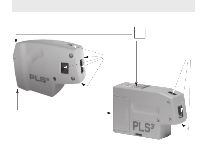
Produktmerkmale
1/4 X 20 ZUBEHÖRHALTERUNG IM UNTERTEIL JEDES GERÄTS
BATTERIEFACHABDECKUNG
VERWENDEN SIE ENTWEDER 3
AA 1,5-VOLT-ALKALI- ODER
NI-CAD-BATTERIEN
3
OPTISCHE FENSTER
(5)
ANZEIGE-LED
EIN: GRÜN
ON
NEIGUNG: ROT
OFF
BATTERIELADUNG
SCHWACH: GELB
EIN AUS
OPTISCHE
FENSTER
(3)
Page 79
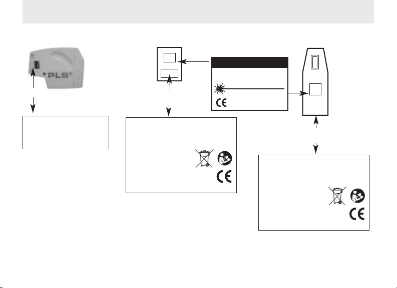
Sicherheitskennzeichen und -hinweiSE
PLS5 - SEITE
PLS5 - RÜCKSEITE
WARNETIKETT
PLS3 -
OBERSEITE
VORSICHT
LASERSTRAHLUNG
STARREN SIE NICHT IN DEN STRAHL UND SEHEN
SIE IHN NICHT DIREKT MIT OPTISCHEN
INSTRUMENTEN AN
BLENDENETIKETT
EXPOSITION VERMEIDEN
AUS DIESER BLENDENÖFFNUNG
TRETEN LASERSTRAHLEN AUS
Der PLS5- und PLS3-Laser
entsprechen den US-FDALeistungsstandards, 21 CFR,
Unterkapitel J.
Der PLS5- und der PLS3-Laser
enthalten eine Halbleiter-Laserdiode
mit einer Wellenlänge von 635 Nanometer.
Die ständige Ausgabe eines einzelnen Strahls überschreitet nie 1,0 Milliwatt.
Schauen Sie niemals direkt in den Laserstrahl und betrachten Sie den Strahl niemals
mit optischen Instrumenten. Schalten Sie den Laser bei Nichtgebrauch aus.
ACHTUNG: DIE VERWENDUNG VON ANDEREN STEUERUNGEN, EINSTELLUNGEN ODER VERFAHREN ALS DEN HIER
ANGEGEBENEN KANN ZU GEFÄHRLICHER STRAHLENEXPOSITION FÜHREN.
ID-NUMMER
ZULASSUNGSETIKETT
GLOBALLY SOURCED. FINALASSEMBLY IN U.S.A.
PATENT #6,938,360 1-800-601-4600
PLS 2550 KERNER BLVD., SAN RAFAEL, CA 94901
S/N:
DATE:
CLASS 2 LASER PRODUCT
PLS5COMPLIES WITH FDA STDS. 21. CFR.,
CHAP. J 1040.10 & 11 EXCEPT FOR DEVIATION
PURSUANT TO LASER NOTICE .60 OF 7/26/2006
BEIM US-PATENTAMT ANGEMELDET
Diese Etiketten sind an jedem PLS-Laser angebracht. Sie dürfen nicht entfernt oder unkenntlich gemacht werden.
MAXIMALER STROMAUSSTOß
WELLENLÄNGE 635-670NM
LASERPRODUKT DER KLASSE II
<1MW
ID-NUMMER ZULASSUNGSETIKETT
GLOBALLY SOURCED. FINALASSEMBLY IN U.S.A.
PATENT #6,938,360 1-800-601-4600
PLS 2550 KERNER BLVD., SAN RAFAEL, CA 94901
S/N:
CLASS 2 LASER PRODUCT
PLS3COMPLIES WITH FDA STDS. 21. CFR.,
CHAP. J 1040.10 & 11 EXCEPT FOR DEVIATION
PURSUANT TO LASER NOTICE .60 OF 7/26/2006
DATE:
4
Page 80
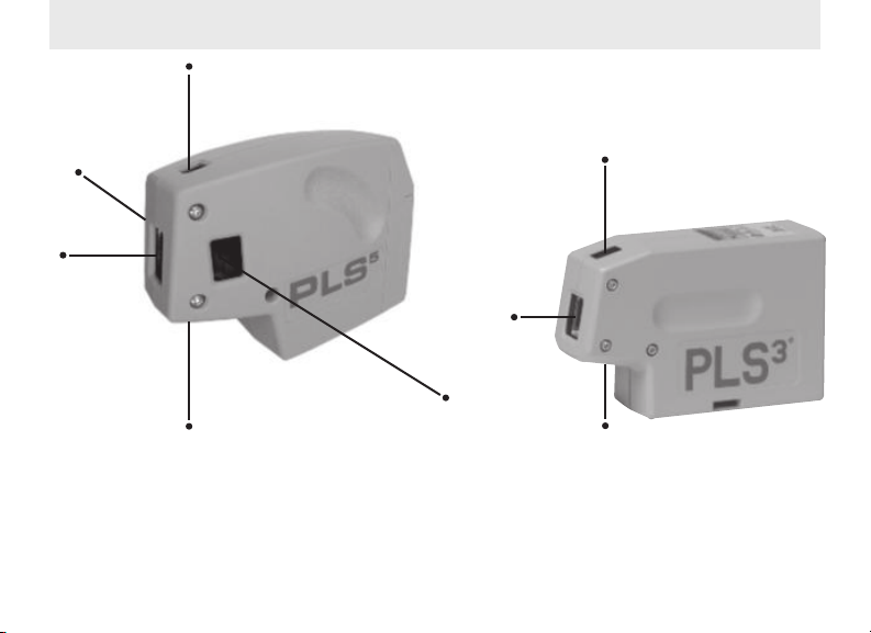
#3
Laserstrahlen
#5
#1
#2
5
PLS
Die fünf Laserstrahlen des PLS5-Lasers sind: 1 Vorwärtsstrahl, 2 Abwärtsstrahl, 3
#4
#3
#1
#2
Aufwärtsstrahl, 4 Linker Strahl, 5 Rechter Strahl Alle PLS5-Strahlen haben die gleiche Helligkeit
und sind rechtwinklig zueinander.
3
PLS
Die drei Laserstrahlen des PLS3-Lasers sind: 1 Vorwärtsstrahl, 2 Abwärtsstrahl, 3
Aufwärtsstrahl
5
Page 81
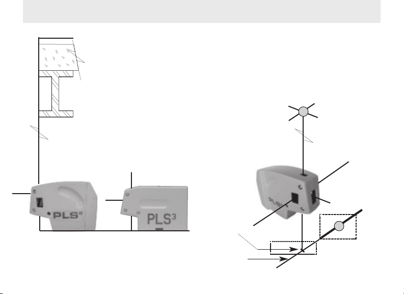
ABB. 2
Lot
Um mit dem PLS5 und PLS3 Modell zu loten, stellen Sie den Abwärtsstrahl 2 über die zu übertragende
Markierung (siehe Abb. 1). Der Aufwärtsstrahl 3 ist innerhalb der Spezifikation genau lotrecht. Sie können Lotmarkierungen nach unten oder oben oder über die Kante einer Gebäude-/Schachtöffnung setzen
(siehe Abb. 2). Verwenden Sie das Bodenstativ mit Ihrem PLS5- oder PLS3-Laser, um den Sichtwinkel
des Abwärtsstrahls 2 zu vergrößern.
Mit dem PLS3- und PLS5-Modell können Sie schnell bestehende Bedingungen auf Lothaltigkeit überprüfen. Verwenden Sie ein Bandmaß und den Aufwärtsstrahl 3. Positionieren Sie den Laser in der Nähe
der Struktur.
Prüfen Sie beliebige Abstände strukturaufwärts oder -abwärts. Es ist
auch möglich, Markierungen von einem Dach oder einer Decke auf den
Boden zu übertragen. Bewegen Sie den Laser, bis der Aufwärtsstrahl 3
auf den Rand oder die Mitte der Deckenkomponente, die übertragen
werden soll, trifft. Markieren Sie den Boden an der Stelle des
Abwärtstrahls 2. Siehe Abb. 2 und 3.
#3
ABB. 3
ABB. 1
LOT-
PUNKT
BODENMARKIERUNG
#2
STRAHL AUF
REFERENZPUNKT
ZENTRIEREN
6
Page 82
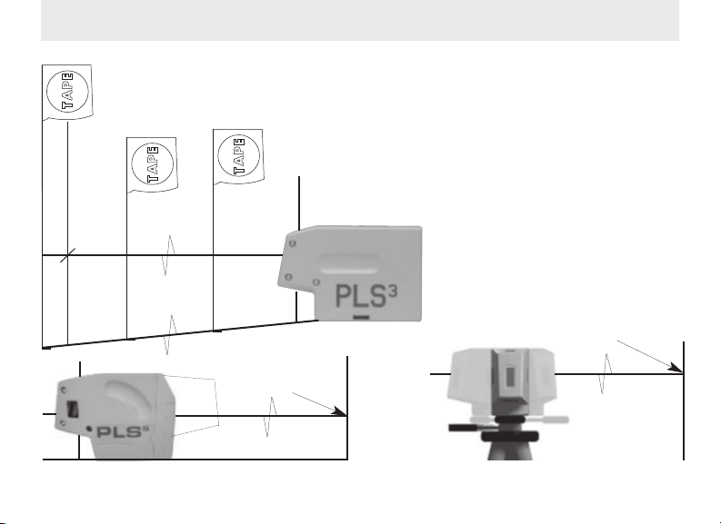
Waage
Mit dem PLS5- und PLS3-Laser lassen sich einfach präzise horizontale und Höhenmarkierungen festlegen. Drehen
Sie die Einheit um ihren Mittelpunkt und halten Sie an, um die gewünschten horizontalen oder Höhenpunkte zu
markieren (siehe Abb. 4). Jede stabile Oberfläche kann verwendet werden. Bei Aufsatz auf einem Stativ oder einer
TAPE
Wandhalterung das Gerät drehen und die Markierung vornehmen (siehe Abb. 5). Achten Sie beim Drehen des
TAPE
CA. 7 M
CA. 3,5 M
PLS5- oder PLS3-Lasers auf einem Stativ darauf, dass der Stativkopf
völlig waagerecht ist. Wenn das Stativ nicht waagerecht ist, können sich
Fehler in den Markierungen ergeben.
TAPE
ABB. 6
Um die Waagrechtigkeit bestehender
Bedingungen zu überprüfen, richten Sie den
Strahl in die Vermessungsrichtung. Mit einem
Bandmaß oder einem Stab mit
Höhenmarkierungen können Abweichungen in
der Waagerechten oder Höhe schnell in verschiedenen Entfernungen erfasst werden (siehe
Abb. 6).
To survey existing conditions for level, point in the
direction to survey. Using a tape or rod with a
bench mark, the variations in level or grade can
be noted quickly at various distances. See Fig. 6.
MARKIERUNG
MARKIERUNG
ABB. 4
ABB. 5
7
Page 83
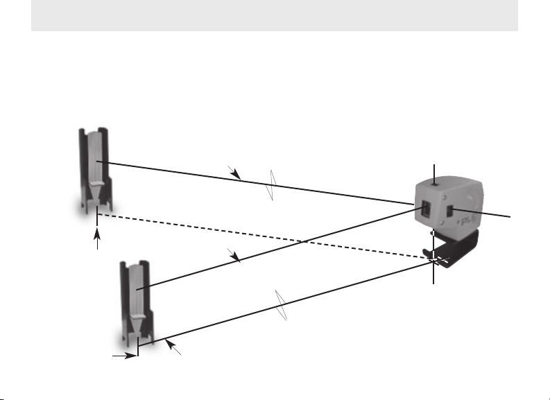
Rechtwinkeligkeit
To establish square, place the PLS5with the #2 down beam over the layout reference line. See Fig.
7. Place the pendulum target on that line, and center #1 forward beam on the center of the target.
Once centered, move the pendulum target to square on #4 left beam or #5 right beam. Make a
mark on the floor or surface near the laser and the second mark at the desired distance from the
laser. See Fig. 7.
STRAHL 5
C
L
MARKIERUNG
C
L
MARKIERUNG
STRAHL 1
ABB. 7
REFERENZLINIE
8
Page 84
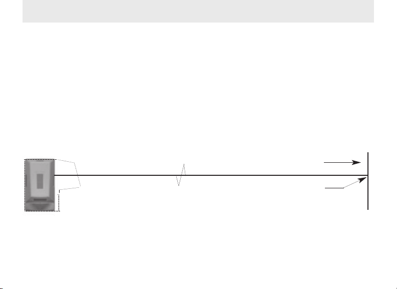
Prüfung der Kalibrierung
Es gibt mehrere einfache Verfahren, um die Kalibrierung und Präzision des PLS5- und PLS3-Lasers zu
überprüfen.
Wir empfehlen die regelmäßige Durchführung dieser Prüfung.
Methode 1 (nur PLS5) Schnelle Überprüfung der Präzision Stellen Sie den PLS5-Laser auf eine sta-
bile Oberfläche im Abstand von ca. 7,5 m von einer geeigneten Wand oder einem geeigneten Ziel
(siehe Abb. 8). Richten Sie den Vorwärtsstrahl 1 auf die Wand oder das Ziel und markieren Sie den
Mittelpunkt der Höhe sorgfältig. Drehen Sie den PLS5-Laser um 90° um seinen Mittelpunkt, bis der
rechte Strahl 5 über der ersten Markierung steht. Überprüfen Sie, ob eine Differenz in der Höhe vom
Mittelpunkt des Vorwärtsstrahls 1 und dem Mittelpunkt des rechten Strahls 5 vorliegt. Wiederholen Sie
das Verfahren zur Überprüfung des Strahls 4. Auf dieser Entfernung darf eine mögliche Differenz
1,5mm nicht übersteigen.
WAND ODER ZIEL
MARKIERUNG
ABB. 8
9
Page 85
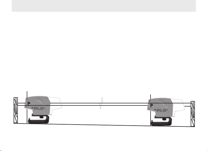
Prüfung der horizontalen Kalibrierung
Methode 2 (sowohl PLS5 als auch PLS3) Genaue Prüfung der Nivellierpräzision. Machen Sie eine
möglichst waagerechte Fläche mit zwei gegenüberliegenden Wänden im Abstand von ca. 8m ausfindig.
Sie können z. B. auch Balkenreste als Ziele verwenden (siehe Abb. 9). Platzieren Sie den Laser ca.
15cm vom Ziel 1 und markieren Sie sorgfältig die Höhe des Vorwärtsstrahls 1 auf dem Ziel. Drehen Sie
den Laser 180° um seinen Mittelpunkt. Markieren Sie den Höhenmittelpunkt des Vorwärtsstrahls 1 auf
dem Ziel 2. Bewegen Sie den Laser auf Ziel 2. Markieren Sie in einer Entfernung von ca. 15cm vom
Ziel den Höhenmittelpunkt des Vorwärtsstrahls 1 auf dem Ziel 2. Drehen Sie den Laser um seinen
Mittelpunkt und markieren Sie den Höhenmittelpunkt auf Ziel 1. Jetzt haben Sie zwei Höhenmittelpunkte
an jedem Ziel. Messen Sie den Abstand zwischen den Mittelpunkten jeder Markierungsgruppe genau.
Wenn der Abstand gleich ist, ist der Laser genau waagerecht. Wenn sich eine Differenz ergibt, subtrahieren Sie eine Messung von der anderen. Diese Methode vergrößert Fehler um einen Faktor 2. Sie
müssen daher diese Differenz durch 2 dividieren, um den genauen Nivellierfehler zu erhalten. Die max.
zulässige Differenz für den PLS5-Laser beträgt. 3mm auf 15 m, bzw. 1,5mm auf 7,5 m. Die max. zulässige Differenz für den PLS3-Laser beträgt. 6mm auf 15m, bzw. 3mm auf 7,5 m.
ZIEL 1
ABB. 9
ZIEL 2
10
Page 86
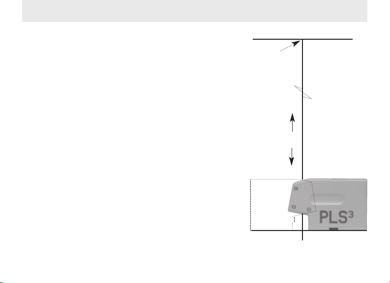
Prüfung der vertikalen Kalibrierung
Methode 3 (sowohl PLS5 als auch PLS3) Genaue
Prüfung der Lotpräzision. Das erfordert eine vertikale
Höhe von ca. 3m und die Fähigkeit, an dieser Höhe eine
Markierung vorzunehmen. Platzieren Sie den Laser so,
dass der Abwärtsstrahl 2 über einer Kreuzmarkierung
genau zentriert ist (siehe Abb. 10). Markieren Sie an der
Oberfläche den Aufwärtstrahl 3 mit einer
Kreuzmarkierung. Drehen Sie den Laser um 180° und
platzieren Sie den Abwärtsstrahl 2 so, dass er genau auf
der gleichen Markierung zentriert ist. Der Aufwärtsstrahl 3
sollte genau über der ersten Markierung sein.
Wenn zwischen Markierung 1 und Markierung 2 eine
Differenz besteht, beträgt der Fehler des Lotstrahls die
Hälfte dieser Differenz.
11
MARKIERUNG
DISTANZ
ABB. 10
Page 87
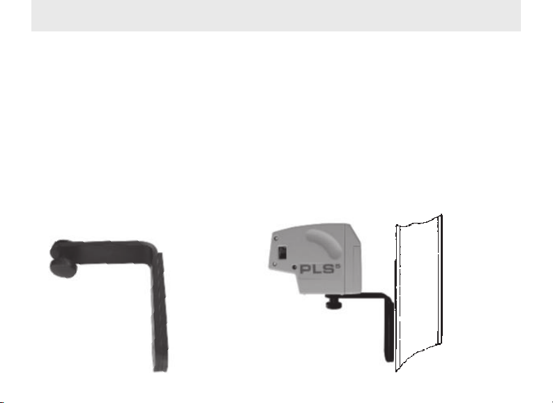
Anleitung für magnetische Halterung
1. Schrauben Sie den _ x 20 Gewindeknopf an die Aufnahme am Unterteil des PLS-Lasers ein.
2. Installieren Sie den PLS-Laser und die Halterung an Stahlpfosten, Stahltürrahmen, I-Trägern,
Zimmermannswinkeln etc.
3. Drehen Sie den PLS-Laser auf den gewünschten Punkt und nehmen Sie Ihre Markierung vor.
Bei Kombination des PLS-Lasers, der magnetischen Halterung, eines herkömmlichen
Tischlerwinkels aus Stahl und einer oder mehrerer Klemmen können Sie den Laser auf unzählige
Arten installieren. Klemmen Sie den Zimmermannswinkel an Betonformteilen, Leitern,
Holzpfosten etc. an. Installieren Sie den PLS-Laser wie oben beschrieben mit der magnetischen
Halterung. Wenn Sie zwei kleine Löcher in der Mitte des langen Teils des Zimmermannswinkels
bohren, kann der Winkel mit Schrauben oder entfernbaren Nägeln an noch nicht endbearbeiteten
Trockenbauwänden angebracht werden. Schieben Sie den PLS-Laser auf dem befestigten
Zimmermannswinkel nach oben oder unten, bis er auf der gewünschten Höhe ist.
STAHLPFOSTEN
ABB. 11
FIG. 12
12
Page 88

Zielpendel
Das PLS5 Zielpendel kann für verschiedene zeitsparende Ausrichtungsaufgaben verwendet werden. Für rechte Winkel: Für beständige Präzision bei der Herstellung oder Überprüfung eines
rechten Winkels verwenden Sie das PLS5 Zielpendel, um den Laserstrahl auf die Bodenfläche zu
übertragen. Zur Feststellung der Rechtwinkligkeit siehe Seite 8 dieser Bedienungsanleitung.
Installieren Sie den PLS5-Laser zur Feststellung der Rechtwinkligkeit immer auf dem Bodenstativ.
Das Zielpendel wurde so entwickelt, dass die Strahlen am besten in dieser Höhe zu sehen sind.
Zur Übertragung von Vertikallinien:
Zur schnellen und präzisen Übertragung von Vertikalmarkierungen
auf eine Wand:
1. Stellen Sie die Vorderseite des PLS5-Lasers so gegen die Wand,
dass der Vorwärtsstrahl 1 auf der zu übertragenden Markierung ist.
(Wenn sich die Markierung auf dem Boden befindet, stellen Sie den
Abwärtsstrahl 2 auf die Markierung.)
2. Platzieren Sie das Ziel so, dass seine Rückseite flach an der Wand
an der gewünschten Höhe anliegt, und verschieben Sie das Ziel, bis
der Aufwärtsstrahl 3 auf dem plastiküberzogenen Ziel zentriert ist.
3. Markieren Sie das obere oder untere Ende der Zielpfeilstifte.
ZIELPENDEL
ABB. 13
13
Page 89
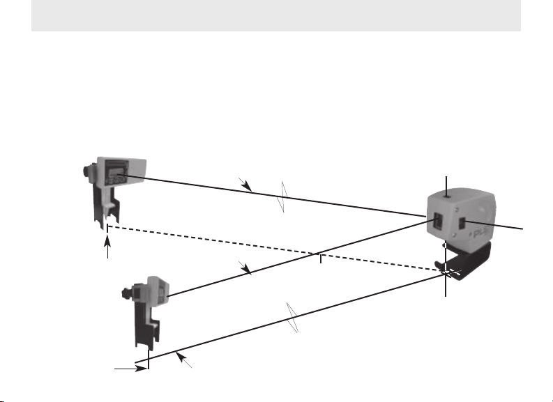
PLS5-System für Innen-/Außenanwendungen
Der PLS5-Laser ist das einzige Punkt-zu-Punkt-Ausrichtwerkzeug für Anwendungen im
Innen- und Außenbereich. Heller Sonnenschein hatte sonst immer die Verwendung von
Lasern mit sichtbarem Strahl auf Projekte im Innenbereich beschränkt. Der PLS5-Laser
in Kombination mit unserem Laserempfänger ermöglicht dem Bauunternehmer das
Layout einer Baustelle bis zu 60-70m selbst unter den hellsten Bedingungen im Freien.
STRAHL 5
„Signalton
Signalton“
C
MARKIERUNG
L
STRAHL 1
„Signalton
Signalton“
C
L
MARKIERUNG
ABB. 7
REFERENZLINIE
14
Page 90
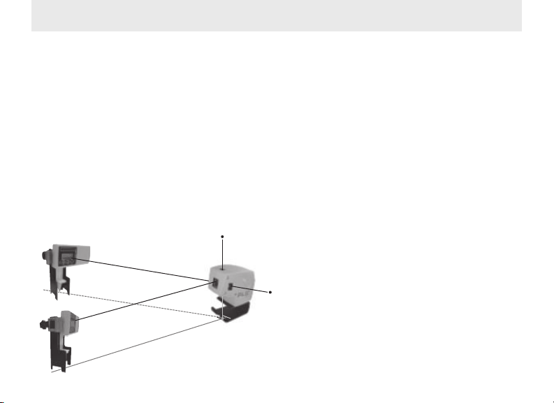
PLS5-Außenanwendungen
BETONBAU
• Verlegung von Schnurgerüsten
• Ausrichtung von Mauerwerk
• Ausrichtung für Schreinerarbeiten
• Ausrichtung von Verankerungspunkten
• Ausrichtung von Pfeilern und
Säulenfundamenten
• Anordnung von Formplatten für
Betonoberbauarbeiten
„Signalton
Signalton“
„Signalton
Signalton“
15
MECHANISCHE UND ELEKTROANLAGEN
• Einbau von Leitungsführungen
• Einbau von Entsorgungs- und
Versorgungsleitungen
• Einbau von Erdgasversorgungsleitungen
RAHMENBAU
• Kontrolllinien auf Betonplatten,
Bodenbelägen und Unterböden
• Ausrichtung von schweren
Stahlaußenrahmen
• Auslegung und Ausrichtung für
Holzrahmen in Wohn- und
Gewerbegebäuden
GLASBAU
• Ausrichtung und Installation von
Fassadenprojekten
Page 91

Technische Daten
PLS
5
PLS
3
Lichtquelle: Halbleiter-Laserdiode Halbleiter-Laserdiode
630-650 nm, sichtbar 630-650 nm, sichtbar
Arbeitsbereich: bis zu 30 m bis zu 30 m
bis zu 70 m mit Empfänger
Genauigkeit: < 3 mm bei 30 m < 6 mm bei 30 m
Nivellierung: Automatisch Automatisch
Nivellierbereich: +/- 6° +/- 6°
Stromversorgung: 3 AA Batterien, Alkali, oder 3 AA Batterien, Alkali, oder
Nicad wiederaufladbar Nicad wiederaufladbar
Betriebszeit: + 30 Stunden Dauerbetrieb + 30 Stunden Dauerbetrieb
Betriebstemperatur: -18o C bis 50o C -18o C bis 50o C
Lagertemperatur: -40o C bis 70o C -40o C bis 70o C
Anzeige: Grüne Lampe: EIN Grüne Lampe: EIN
Rote Lampe: ÜBERSCHREITET Rote Lampe: ÜBERSCHREITET
NEIGUNG NEIGUNG
Gelbe Lampe: BATTERIE Gelbe Lampe: BATTERIE
SCHWACH
SCHWACH
Staub und Feuchteschutz: Staub- und Spritzwassergeschützt Staub- und Spritzwassergeschützt
Abmessungen: 5,1 cm x 10,2 cm x 12,1 cm 4,5 cm x 12,7 cm x 9,5 cm
Gewicht (mit Batterien): 0,5 kg 0,3 kg
16
Page 92

PLS Lab Technicians
PLS•Pacific Laser Systems
2550 Kerner Blvd., San Rafael, CA 94901 USA
www.plslaser.com o Tel.: +1 800 601 4500
Page 93
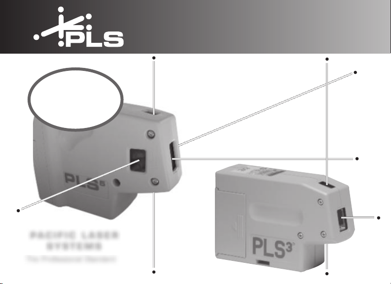
NOUVEAU
PLS5
PACIFIC LASER
SYSTEMS
The Professional Standard
GUIDE D’UTILISATION
Page 94

Table des Matières
Bienvenue chez Pacific Laser Systems. Nous sommes ravis que vous ayez choisi l’outil
laser le plus précis au monde. Nous nous vouons à offrir les outils du plus haut niveau
de qualité de fabrication utilisant les matériaux de la plus haute qualité disponible.
Les outils laser de PLS furent développés par des utilisateurs pour fournir à chaque
corps de métier, l’information d’alignement requise de façon efficace.Des milliers de nos
clients certifieront de l’économie de temps et d’argent réalisés grâce à la commoditéé,
polyvalence et performance des outils laser de PLS. Et dans le cas où votre outil devrait
être réparé, vous pouvez être assuré d'une attention immédiate et professionnelle.
CONTENU
Introduction ........................................1
Entretien………………………..........…2
Garantie…………………………...........2
Parties fonctionnelles……………........ 3
Marquage et Instructions de sécurité..4
Faisceaux…………………………........5
Aplomb………………………............….6
Niveau……………………….............…...7
Angle droit……………………..........…....8
Vérification de l’étalonnage...........9,10,11
Support magnétique…………...........… 12
Cible…………………………..............…13
Système PLS5 extérieur..................14,15
Fiche technique du PLS5 et du PLS3..16
1
Page 95

Entretien
L’entretien du PLS3 ou du PLS5 tient primordialement du bon sens.. Retirez les piles de l’unité si le laser doit
être entreposé pour une durée importante. Gardez la fenêtre optique propre en la nettoyant avec un linge doux
ou tissu pour nettoyage de lentilles photographiques.Évitez d’entreposer pendant une période prolongée sous
des températures élevées ou basses.
Garantie
Ce produit est garanti par Pacific Laser Systems (PLS) envers l’acheteur initial, contre tout défaut ou vice de
fabrication pour un usage normal pendant une période de deux ans à compter de la date d’achat. Pendant la
période de garantie, et après avoir fourni la preuve de la date d’achat, le produit sera réparé ou remplacé par
PLS (par un modèle identique ou similaire de notre choix) sans frais pour les pièces ou la main-d’?uvre.
L’acheteur supportera les frais d’expédition, d’emballage et d’assurance. Après réparation ou remplacement,
l’appareil sera renvoyé au client, frais d’envoi prépayés. La garantie ne s’appliquera pas à ce produit s’il montre des signes de mauvaises ustilisations, de chocs ou de bris. Sans limitation à ce qui précède, une fuite de
pile, des traces de coups ou de gouges sur le boîtier en matière plastique, des fenêtres optiques brisées, l’endommagement de la membrane d’interrupteur/de diode électroluninescente (DEL) seront interprétés comme
le résultat d’un mauvais usage ou d’un abus.L’altération ou le retrait des étiquettes d’avertissement ou de certification annulera cette garantie.
Ni cette garantie ni aucune autre garantie, expresse ou tacite, incluant toutes garanties tacites de qualité
marchande, ne s’étendront au-delà de la période de garantie. Aucune responsabilité ne sera assumée pour
tout dommage accidentel ou consécutif. Cette garantie vous donne des droits légaux spécifiques et vous pourriez avoir d’autres droits qui varient d’un état juridique à l'autre.
Les outils PLS ne possèdent aucune partie réparable par l’utilisateur. En cas de besoin de réparation,
adressez-vous au centre de service le plus rapproché.
2
Page 96
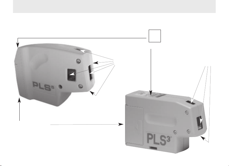
PARTIES FONCTIONNELLES
ACCESSOIRE DE MONTAGE À FILETS DE 1/4 X 20
DANS LA BASE DE TOUTES LES UNITÉS
COMPARTIMENT
À PILES
UTILISEZ TROIS (3)
PILES AA (NICKELCADMIUM OU
ALCALINES)
3
FENÊTRES
OPTIQUES
(5)
IVOYANT DEL
EN MARCHE : VERT
ON
INCLINÉ : ROUGE
OFF
PILES FAIBLES : AMBRE
(OFTEN TRANSLATED AS « ORANGE »)
FENÊTRES
OPTIQUES
(3)
Page 97
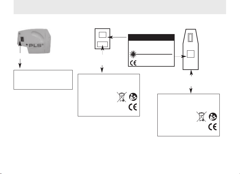
Marquage et instructions de sécurité
CÔTÉ DU PLS5
DOS DU PLS5
DESSUS DU PLS3
ÉTIQUETTE D’AVERTISSEMENT
PRÉCAUTION
RADIATION DU LASER
NE PAS FIXER LE FAISCEAU OU LE
REGARDER DIRECTEMENT AVEC DES
ÉTIQUETTE À L’OUVERTURE
ÉVITER L’EXPOSITION
ÉMISSION DE RAYONNEMENT LASER
PAR CETTE OUVERTURE
Les appareils PLS5 et PLS3
sont conformes aux normes de
performance de la FDA (Food &
Drug Administration des ÉtatsUnis) chapitre 21 CFR,
sous-chapitre J.
ÉTIQUETTE DE CERTIFICATION DU
NUMÉRO D’IDENTIFICATION
GLOBALLY SOURCED. FINALASSEMBLY IN U.S.A.
PATENT #6,938,360 1-800-601-4600
PLS 2550 KERNER BLVD.,SAN RAFAEL, CA 94901
S/N:
CLASS 2 LASER PRODUCT
PLS5COMPLIES WITH FDA STDS. 21. CFR.,
CHAP. J 1040.10 & 11 EXCEPT FOR DEVIATION
PURSUANT TO LASER NOTICE .60 OF 7/26/2006
BUREAU D’ENREGISTREMENT DES BREVETS AMÉRICAINS.
DATE:
Les instruments PLS5 et PLS3 contiennent une diode laser semiconductrice
de longueur d’onde de 635 nanomètres. La sortie continue de tout faisceau unique n’excèdera jamais 1 milliwatt. Ne regardez jamais le faisceau
INSTRUMENTS OPTIQUES
PUISSANCE DE SORTIE MAXIMUM <1MW
LONGUEUR D'ONDE 635-670NM
PRODUIT LASER CLASSE II
ÉTIQUETTE DE CERTIFICATION DU NUMÉRO
GLOBALLY SOURCED. FINALASSEMBLY IN U.S.A.
PATENT #6,938,360 1-800-601-4600
PLS 2550 KERNER BLVD.,SAN RAFAEL, CA 94901
S/N:
CLASS 2 LASER PRODUCT
PLS3COMPLIES WITH FDA STDS. 21. CFR.,
CHAP. J 1040.10 & 11 EXCEPT FOR DEVIATION
PURSUANT TO LASER NOTICE .60 OF 7/26/2006
D’IDENTIFICATION
DATE:
laser fixement ni directement avec des instruments optiques. Éteignez le laser lorsque vous ne l’utilisez pas.
ATTENTION : l'usage de commandes, réglages ou procédures autres que ceux spécifiés dans ce guide peut
entraîner une exposition à un rayonnement dangereux.
Ces étiquettes sont placées sur chaque laser PLS. Elles ne doivent être ni enlevées ni laissées en condition
illisible.
4
Page 98
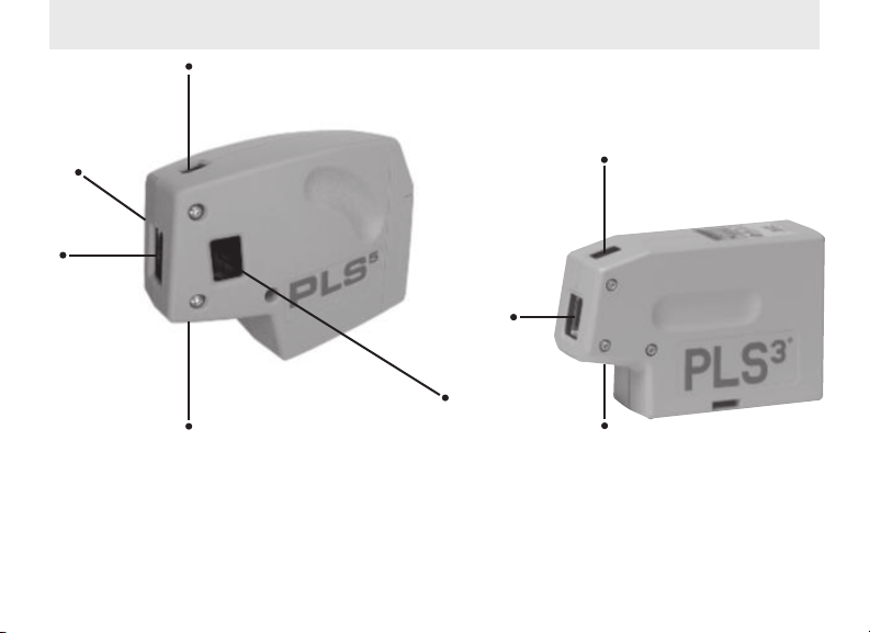
#3
Faisceaux
#5
#1
#2
5
PLS
Les cinq faisceaux du PLS5 sont : n° 1, faisceau avant ; n° 2, faisceau vers le bas ; n° 3,
#4
#3
#1
#2
faisceau vers le haut ; n° 4, faisceau gauche ; n° 5, faisceau droit. Tous les faisceaux du PLS5 ont
la même intensité et sont à angle droit l’un par rapport à l’autre.
3
PLS
Les trois faisceaux du PLS3 sont : nN° 1, faisceau avant ; n° 2, faisceau vers le bas ; n° 3,
faisceau vers le haut.
5
Page 99
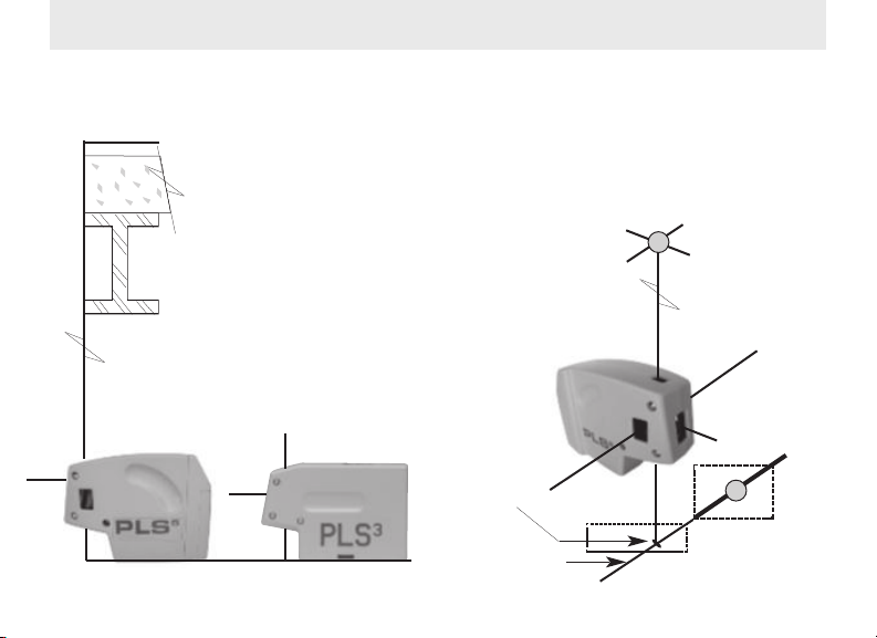
FIG. 2
Aplomb
Pour établir l’aplomb avec le PLS5 et PLS3, placez le faisceau du bas (n° 2) par-dessus
la marque à transposer.Voir la figure 1. Le faisceau vers le haut (n°3) est exactement
d’aplomb en dedans des tolérances spécifiées. Vous pouvez cibler des marques d’aplombvers le bas et vers le haut ou en angle par dessus la toiture d’un édifice, l’ouverture d’un
puits d’ascenseur ou support de plancher ou autre. Voir la figure 2. Pour accroître l’angle
de vue du faisceau n° 2 vers le bas, utilisez le socle de votre PLS5 ou PLS3.
Les appareils PLS3 et PLS5 peuvent rapidement matérialiser
les conditions d’aplomb. Utilisez un ruban à mesurer et le
faisceau n° 3 vers le haut. Positionnez le laser près de la
structure. Contrôlez l’une ou l‘autre des distances vers le haut ou
vers le bas. Il est également possible de transposer les marques
d’une toiture ou plafond sur le plancher. Déplacez le laser
jusqu’à ce que le faisceau n° 3 vers le haut rejoigne le bord ou
le centre de la composante du plafond à transposer.
Marquez le plancher au faisceau n° 2 vers le bas.
Voir les figures 2 et 3.
#3
FIG. 1
POINT
D’APLOMB
PLAN
DE PLANCHER
#2
CENTREZ LE
FAISCEAU
SUR LE PLAN
6
Page 100
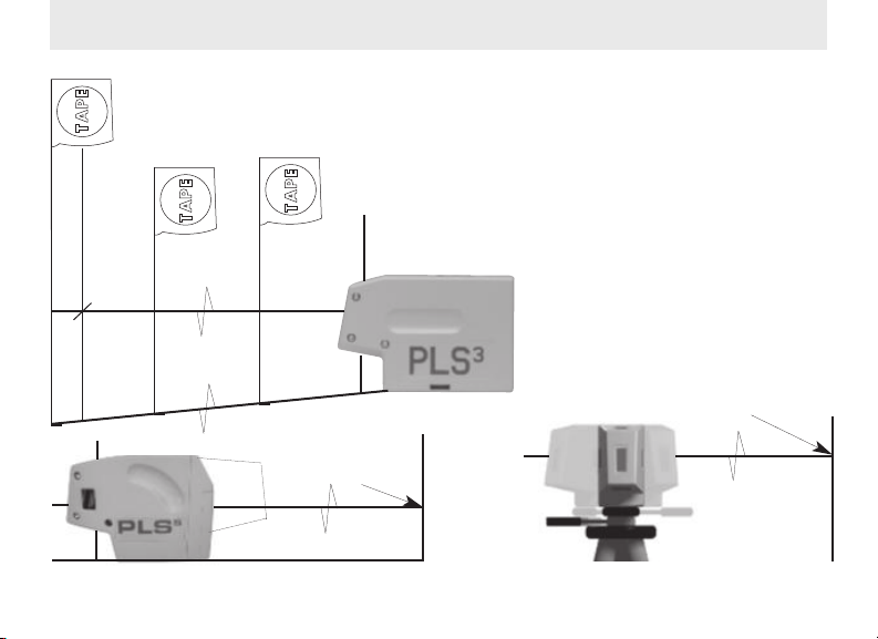
Niveau
Avec les PLS5 et PLS3, vous pouvez établir facilement et marquer de façon précise les pentes et
niveaux des sites. Faites pivoter l’unité autour de son centre, en l’arrêtant pour marquer les points de
pente ou de niveau désirés. Voir la figure 4.Toute surface stable peut être utilisée. En montage sur un
TAPE
6 M
TAPE
3 M
trépied ou support mural, faites pivoter et marquez. Voir la figure 5. Lorsque
vous faites pivoter votre PLS5 ou PLS3 sur un trépied, assurezvous que la tête du trépied soit parfaitement au niveau. Une
erreur de marquage peut dépendre d’un trépied n’étant pas au
TAPE
niveau.
Pour vérifier les conditions actuelles de
niveau, pointez dans la direction à
inspecter. En utilisant un ruban à mesurer
ou bâton de mesure d’arpenteur, les variations de niveau ou de pente peuvent facilement et immédiatement être remarquées à
différentes distances. Voir la figure 6.
FIG.6
MARQUE
MARQUE
FIG. 4
FIG. 5
7
 Loading...