

Page 1
O PERATING M ANUAL
PACIFIC LASER
SYSTEM S
The Professional Standard
NEW
PLS5
Page 2

Tabl e of Cont ent s
1
Welcome to PLS laser tools. We believe you have chosen the finest laser tool in
the world. We are committed to the highest quality standards in workmanship and
materials.
PLS laser tools were developed by contractors to provide every trade with accurate and
efficient alignment information. Thousands of our customers will attest to the savings of
time and money through the performance, convenience and versatility of PLS laser
tools.You can be confident of prompt service to your laser, should the need arise.
CONTENTS
Introduction ...................................
About The Company...............1A,1B
Maintenance .................................
Warranty..........................................
Features..........................................
Safety Labeling & Instructions.......
Beams.............................................
Plumb...........................................6
Level.............................................
Square.........................................
Check Calibration ..............
Magnetic Bracket........................
Ta rg e t.. . .. .. .. .. .. .. .. . .. .. .. .. .. .. .. . .. .. .. .. .
PLS5 Exterior System...........
PLS5 & PLS3 Specifications ......16
1
B
2
2
3
4
5
7
8
9,10,11
12
13
14,15
Page 3

About Pacif ic Laser Syst ems
The PLS family of laser tools was developed to give contractors the ability to
transfer critical layout reference points for any job site task. All are self-leveling,
compact and durable laser alignment tools.
What sets PLS•Pacific Laser Systems apart from the rest? Built by contractors
for contractors, PLS tools were developed out of necessity by professionals with
over 50 years of experience in commercial and residential interior and exterior
layout. PLS founders were contractors first before becoming manufacturers of
the finest point-to-point alignment tools in the world.
Point-to-point reference means you can plumb with a PLS5 or PLS3 literally
from floor to ceiling or from 50 feet off the ground. With our PLS5, squaring or
layout of 90° angles can be done faster than ever before.
1A
Page 4

About Pacif ic Laser Syst ems
1B
Our target market is the professional contractor who needs a dependable align-
ment tool that will speed production and save money. General Contractors and
project managers use the PLS laser to check existing conditions before work
begins. They also use it to judge the work performed by subcontractors.
Subcontractors use PLS lasers for layout on the job site. As much as 25% of the
work day can be spent on layout. The PLS5 system gives square reference eas-
ily and quickly. No more 3-4-5. The unique PLS cantilever design allows easy
sight of the opposing reference points and is proven to be effective in installing
curtain walls, foundations, columns, skylights, doors, cabinetry and much more.
The portability and utility of PLS lasers make them attractive alignment tools
when bubble vial levels or rotary lasers are too cumbersome or too limited to do
the job.
The PLS5 and PLS3 are registered trademarks of PLS•Pacific Laser Systems.
The PLS5 utilizes our patented technology, U.S. Patent No. 5,144,487.
Page 5

Maint enance
Wa r r a n t y
Good care of the PLS3or PLS5is primarily common sense care. Remove the batteries from unit
if the laser is to be stored for a considerable period of time. Keep the optic windows clean using a
soft cloth or photographic grade cleaning tissue. Avoid storage conditions of prolonged heat or cold.
This product is warranted by PLS • Pacific Laser Systems to the original purchaser to be free from
defects in material and workmanship under normal use for a period of one year from the date of
purchase. During the warranty period, and upon proof of purchase, the product will be repaired or
replaced (with the same or similar model at our option), without charge for either parts or labor
through PLS. The purchaser shall bear all shipping, packing and insurance costs. Upon completion of the repair or replacement, the unit will be returned to the customer, freight prepaid. The warranty will not apply to this product if it has been misused, abused or altered. Without limiting the
foregoing, battery leakage, dents or gouges to the plastic housing, broken optic windows, damage
to the switch/LED membrane are presumed to result from misuse or abuse. Tampering with or
removal of the caution or certification labels voids this warranty.
Neither this warranty or any other warranty, express or implied, including implied warranties of merchantability, shall extend beyond the warranty period. No responsibility is assumed for any incidental or consequential damages. This warranty gives you specific legal rights, and you may have
other rights which vary from state to state.
There is nothing an owner can do in the way of service or maintenance on PLS tools. Contact
PLS or your local service center for repairs.
2
Page 6
Feat ur es
3
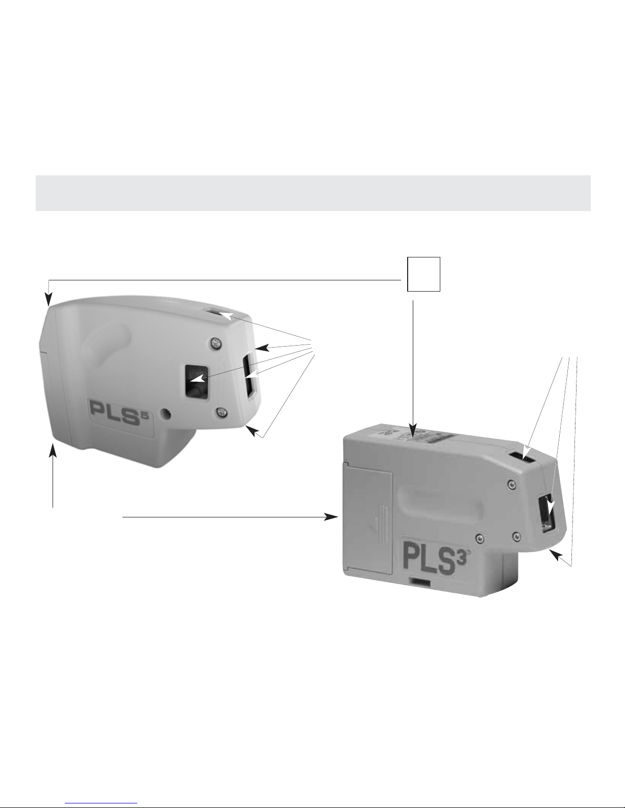
BATTERY DOOR
US E EI THER 3 A A 1. 5 V
ALKALINE OR NICAD
BATTERIES
INDICATOR LED
ON : G R E EN
TI LT: RED
BATTERY LOW: AMBER
OPT I C WI N D OWS
(5)
1/ 4 X 2 0 A C C E S S ORY M OU N T I N B A S E OF E A C H U N I T
OPT I C WI N D OWS
(3)
ON
OFF
Page 7
4
PLS
5
COMPLIES WITH FDA STDS.
21 CFR, SUBCHAPTER J 1040, 10 AND 11
EXCEPT FOR DEVIATION PURSUANT TO NOTICE 50
DATED 07/26/01
SERIAL NUMBER:
DATE:
PATENT #5144437
2550 KERNER BLVD., SAN RAFAEL, CA 94901 USA
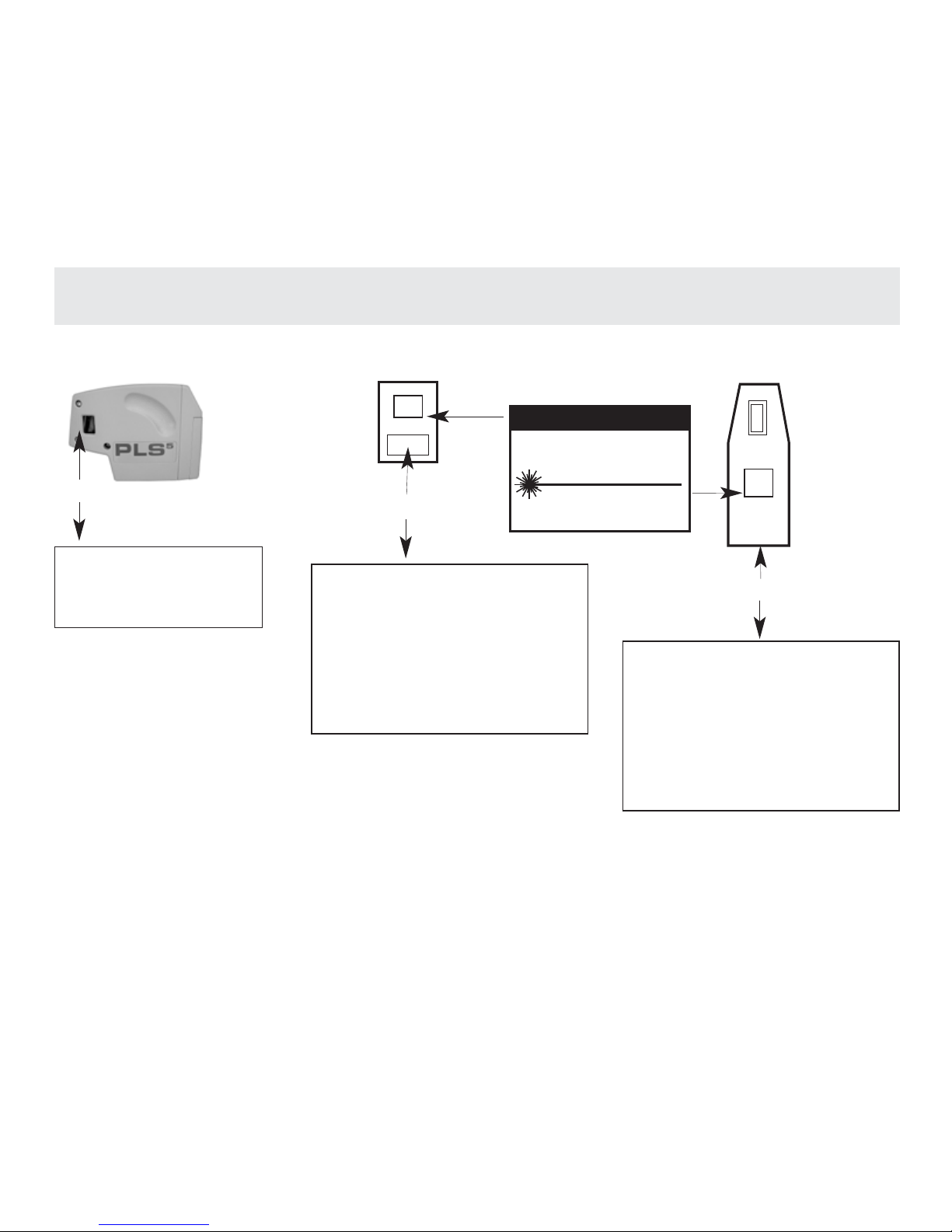
ID# CERTIFICATION LABEL
PLS 5 SIDE
PLS 5 BA CK
AVO I D EX P O S U R E
LASER RADIATION EMITTED
FROM THIS APERTURE
REGISTERED U.S. PATENT OFFICE.
PLS 3 TOP
APERTURE LABEL
PLS5and PLS3comply with
US FDA performance standards,
21 CFR, Subchapter J.
The PLS
5
and PLS3contain
a semiconductor laser diode
with a wavelength of 635 nanometers.
The continuous output of any single beam never exceeds 1.0 milliwatts.
Never stare directly into the laser beam or view the beam with optical
instruments. Turn the laser off when not in use.
CAUTION: USE OF CONTROLS, ADJUSTMENTS OR PROCEDURES
OTHER THAN THOSE SPECIFIED HEREIN MAY RESULT IN HAZARDOUS RADIATION EXPOSURE.
These labels are attached to every PLS laser. These are not to be removed or defaced.
Saf et y Label ing & Inst r uct ions
WA R N I N G L A B E L
ID# CERTIFICATION LABEL
CAUTION
LASER RADIATION
DO NOT STARE INTO BEAM OR VIEW
DIRECTLY WITH OPTICAL INSTRUMENTS
MAX OUTPUT POWER <1mW
WAVELENGTH 635-670nm
CLASS II LASER PRODUCT
PLS
3
COMPLIES WITH FDA STDS.
21 CFR, SUBCHAPTER J 1040, 10 AND 11
EXCEPT FOR DEVIATION PURSUANT TO NOTICE 50
DATED 07/26/01
SERIAL NUMBER:
DATE:
2550 KERNER BLVD., SAN RAFAEL, CA 94901 USA
Page 8
Beams
5
#1
#1
#5
#4
PLS
5
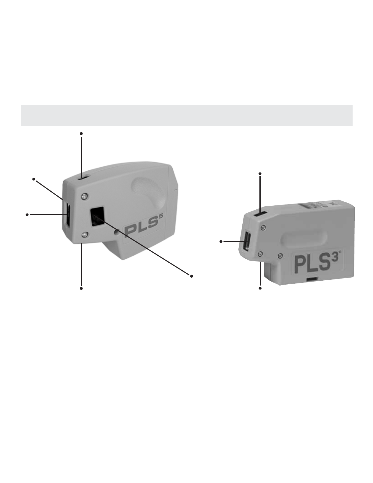
The five beams of the PLS5are: #1 Forward Beam, #2 Down Beam, #3 Up Beam,
#4 Left Beam, #5 Right Beam. All PLS5 beams have the same brightness and are
square to each other.
PLS
3
The three beams of the PLS3are: #1 Forward Beam, #2 Down Beam, #3 Up Beam.
#2
#3
#3
#2
Page 9
Pl umb
6
#2
CE N TE R B E A M
ON L AYOU T
FIG. 2
FLOOR
LAYOUT
PLUMB
POINT
FIG. 3
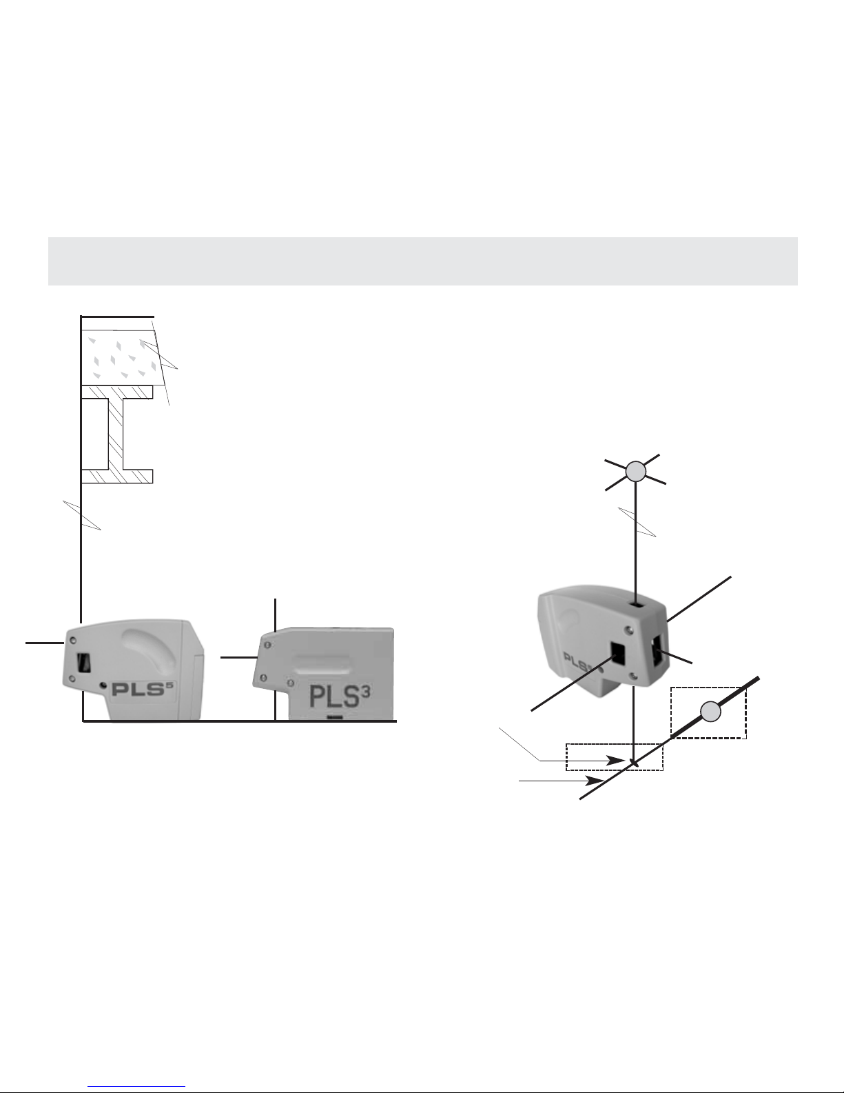
To es ta bl is h p l um b w it h t h e P LS5and PLS3, place the #2 down beam over the mark to be
transposed. See Fig.1. The #3 up beam is exactly plumb within specification. You can
shoot plumb marks down and up, or cantilevered over the edge of a building/shaft opening
or floor track, etc. See Fig.2. Use the floor stand with your PLS5or PLS3 to increase the
sight angle of the #2 down beam.
The PLS3and PLS5can quickly survey existing conditions for plumb. Use a tape
and #3 up beam. Position the laser near the structure.
Check any distance up or down the structure. It is also
possible to transpose marks from a roof or ceiling down to
the floor. Move the laser until the #3 up beam hits the edge or
center of the ceiling component to be transposed. Mark the
floor at the #2 down beam. See Fig. 2 and 3.
#3
FIG. 1
Page 10
Level
7
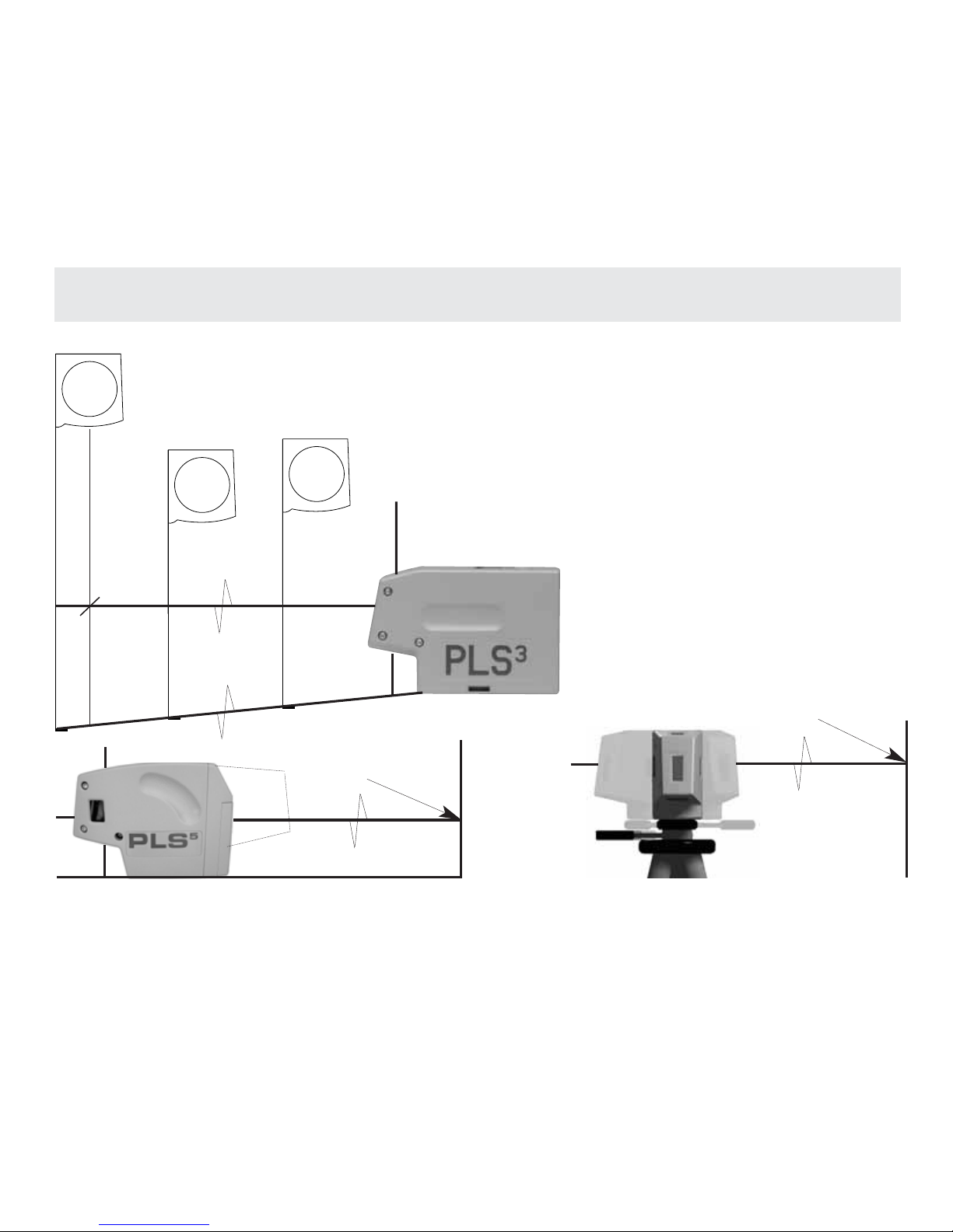
Precise level and grade marks are easily established with the PLS5and PLS3.Swivel the
unit about its center, stopping to mark the desired level or grade points. See Fig. 4. Any
stable surface can be used. When mounted on a tripod or wall mount, swivel and mark.
See Fig. 5. When turning your PLS
5
or PLS3on a tripod
be sure tripod head is perfectly level. Error in marks can
result with tripod out of level.
To s ur v ey e xi st i ng co nd i ti on s f or l ev el ,
point in the direction to survey. Using
a tape or rod with a bench mark, the
variations in level or grade can be
noted quickly at various distances.
See Fig. 6.
MARK
FIG. 4
FIG. 5
MARK
TA P E
TA P E
TA P E
FIG.6
20’
10 ’
Page 11
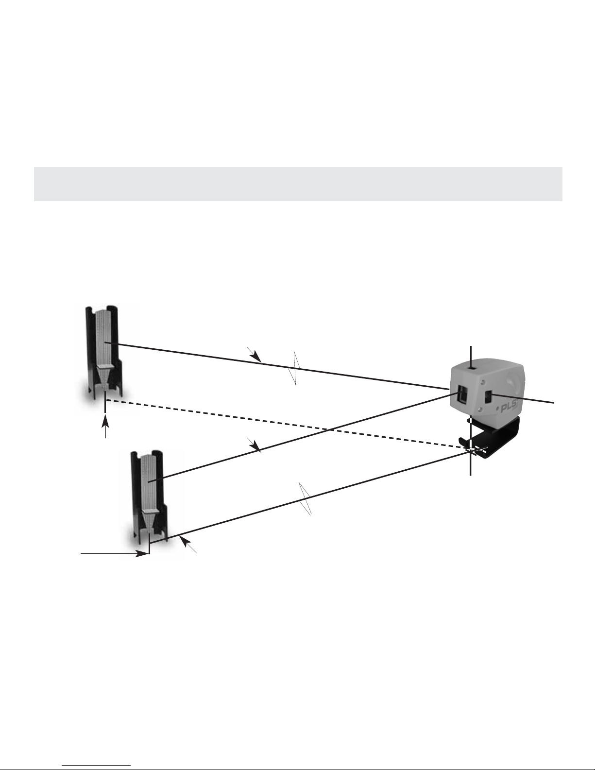
To e st ab li s h sq u ar e, p la c e th e PL S5with the #2 down beam over the layout reference line. See Fig.
7. Place the pendulum target on that line, and center #1 forward beam on the center of the target.
Once centered, move the pendulum target to square on #4 left beam or #5 right beam. Make a
mark on the floor or surface near the laser and the second mark at the desired distance from the
laser. See Fig. 7.
C
L
8
FIG. 7
MARK
BEAM # 1
BEAM # 5
Squar e
LAYOUT OR REFERENCE LINE
C
L
MARK
Page 12
Checking Cal ibr ation
9
FIG. 8
WA L L O R TA R G E T
MARK
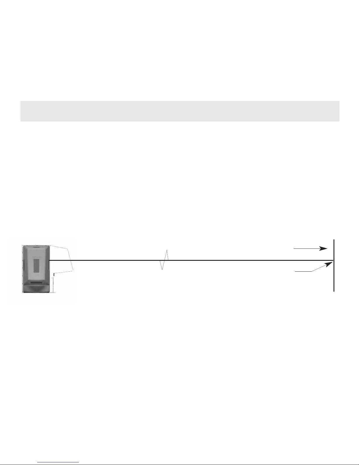
There are several easy methods to check the calibration and accuracy of the PLS5 and PLS3.
We recommend that you check this periodically.
METHOD 1 (PLS
5
only) Quick Check of Performance Accuracy. Place the PLS5on a stable
surface 25’-0” or more from a suitable wall or target. See Fig. 8. Point the #1 forward beam at
the wall or target and carefully mark the center of elevation. Swivel the PLS590˚ on its center
until the #5 right beam is over the first mark. Check to see if there is any difference in elevation
from the center of #1 forward beam and the center of #5 right beam. Repeat to check #4 beam.
At 50’-0” the difference should not be greater than 1/8.” At 25’-0” the difference should not be
greater than 1/16.”
Page 13
Checking Cal ibr ation
10
FIG. 9
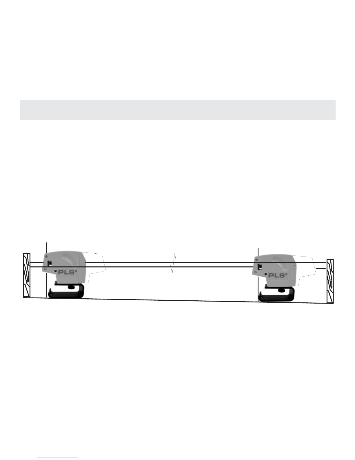
METHOD 2 (both PLS5and PLS3) Exact Check of Level Accuracy. Find a fairly level site line
(preferably a concrete slab) 25’-0” or greater with two opposing walls. You can also use scrap
2 x 4s, for example, as targets. See Fig. 9. Place the laser about 6” from target #1, and carefully
mark the elevation of #1 forward beam on the target. Swivel the laser 180˚ on its center. Mark
the elevation center of #1 forward beam on target #2. Move the laser to target #2. At 6” from the
target, mark the center of elevation of #1 forward beam on target #2. Swivel the laser on its center and mark center of elevation at target #1. You now have two centers of elevation at each target. Carefully measure the distance between centers of each set of marks. If the distance is the
same, the laser is exactly level. If there is a difference, subtract one measurement from the other.
This method magnifies any error by a factor of two. Therefore, divide this difference by two to find
the exact error of level. The maximum error for the PLS
5
is 1/16” at 25’-0” or 1/8” at 50’-0.” The
maximum error for the PLS3is 1/8” at 25’-0” or 1/4” at 50’-0.”
TA R G E T # 1
TA R G E T # 2
Page 14
Checking Cal ibr ation
11
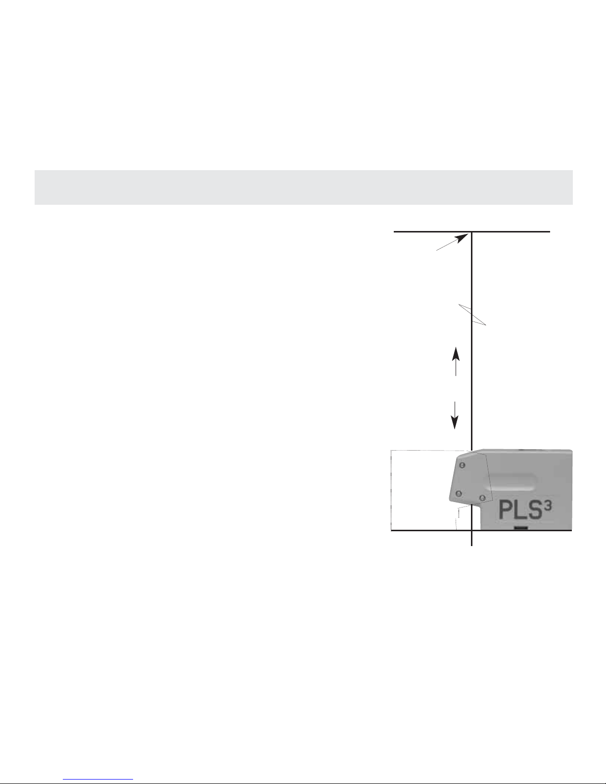
METHOD 3 (both PLS5and PLS3) Exact Check of Plumb
Accuracy. This requires significant vertical height (minimum 10’-0”) and the ability to mark at that height. Place
the unit with the #2 down beam exactly centered on both
axes over a cross mark. See Fig. 10. At the surface
above, mark both axes of #3 up beam. Rotate the laser
180˚ and place the #2 down beam exactly centered on the
same mark. The #3 up beam should be exactly over the
first mark.
If there is a difference between mark #1 and mark #2,
the error of the plumb beam is one half that difference.
MARK
DIST A NCE
FIG. 10
Page 15
Magnet ic Br acket Inst r uct ions
12
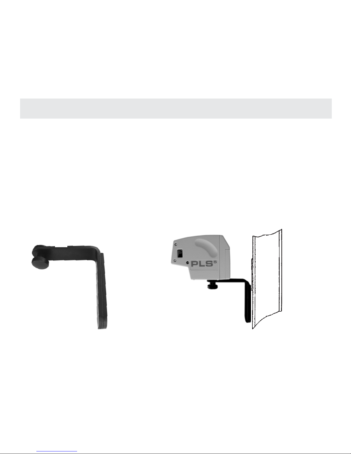
To us e t h e m ag ne t ic br a ck e t w it h t h e P LS l as er :
1.Screw the 1/4 x 20 threaded knob to the mount on the base of the PLS laser.
2.Mount the PLS laser and bracket to steel studs, steel door frame, I-beams, carpenter’s
square, etc.
3.Rotate the PLS laser to desired point and make your mark.
Combine the PLS laser, the magnetic bracket, a standard steel carpenter’s framing square and one
or more clamps and you have the ability to mount the laser in unlimited ways. Clamp carpenter’s
square to concrete forms, ladders, wood studs, etc. Attach the PLS laser with magnetic mount as
described above. If you drill two small holes centered on the long section of the carpenter’s square,
the square can be attached to unfinished drywall partitions with screws or removable nails. Slide
the PLS laser up and down the mounted carpenter’s square to the precise desired height.
FIG. 11
FIG. 12
STEEL STUD
Page 16
Pendul um Tar get
13
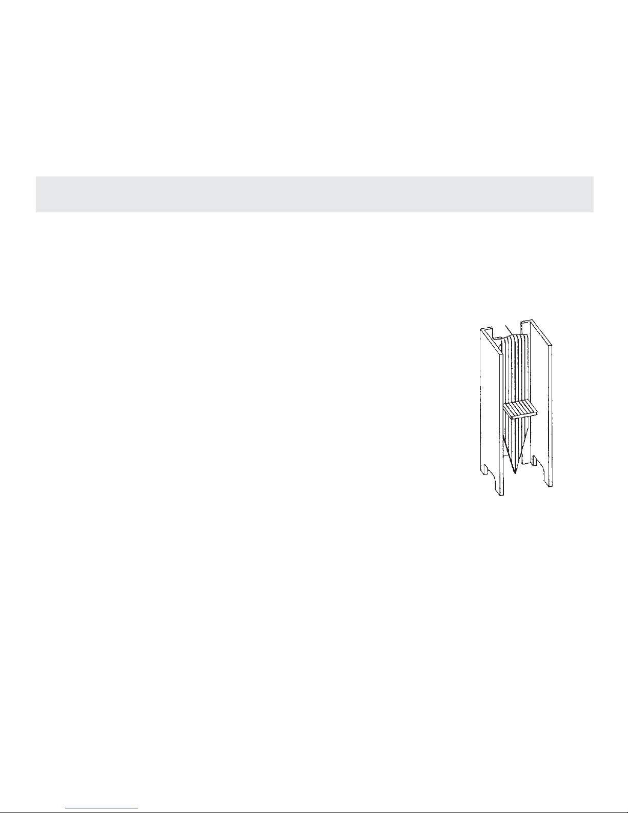
Use the PLS5pendulum target for a variety of time saving alignment tasks. For square: For consistent accuracy in establishing or checking square, use the PLS5target to transfer the laser
beam to the floor surface. To establish square, see page 8 of this manual. Always mount the
PLS
5
laser on the floor stand when establishing square. The pendulum target is designed so the
beams are best seen at this height.
For transfer of vertical lines:
To tr an s fe r ve r t ic a l m ar k s q ui ck l y a nd a cc ur a te ly to a wa l l:
1.Place the front of the PLS
5
laser against the wall with the #1
forward beam on the mark to be transferred. (If the mark is on the
floor, place the #2 down beam over the mark.)
2.Place the target with its back flat against the wall at the desired
height and move the target until the #3 up beam is centered on
the plastic lined target.
3.Mark the top or bottom of the target arrow pins.
PENDULUM TA RGET
FIG. 13
Page 17
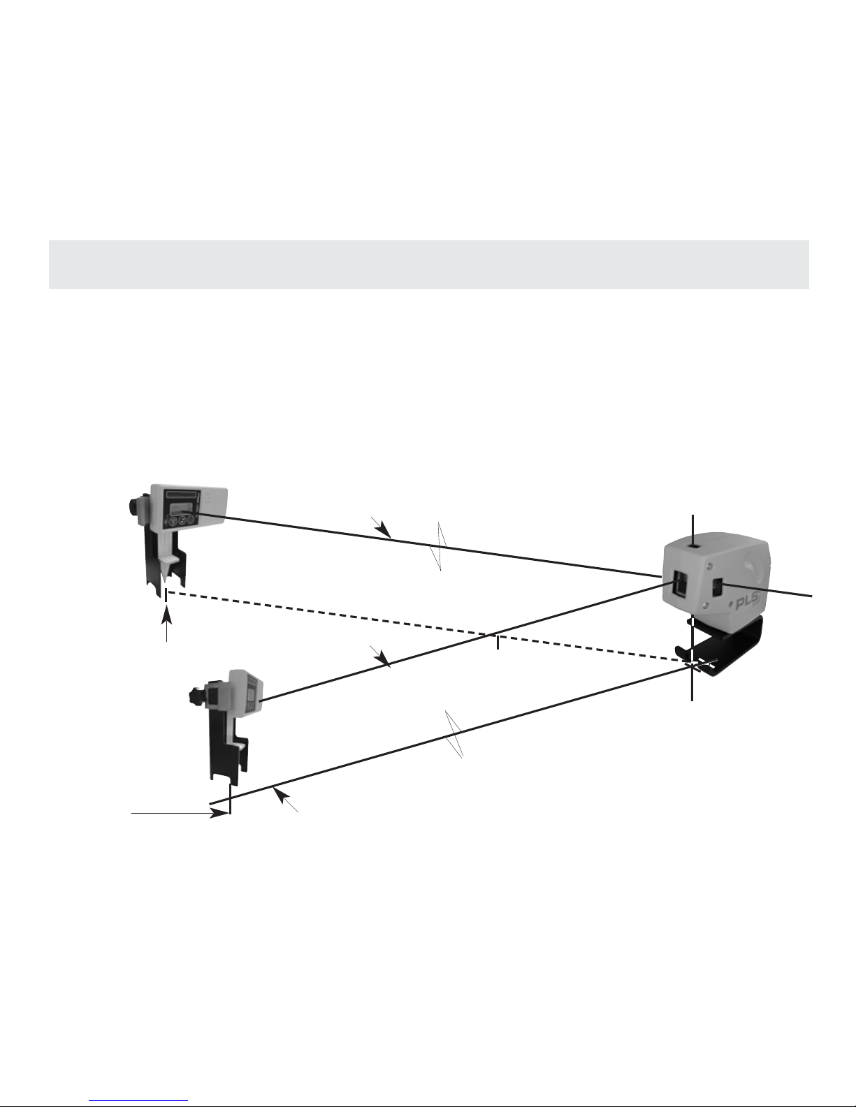
The PLS5 is the only point-to-point layout tool for use on both indoor and outdoor job
sites. Bright sunshine has traditionally limited the use of visible beam lasers to interior
projects. The PLS5 partnered with our laser receiver gives the contractor the ability to
accurately lay out a job site up to 250 + feet, even in the brightest outdoor conditions.
The PLS5 can also be used inside, without the receiver, for all point-to-point
alignment tasks.
PLS5 Syst em Int er ior - Ext er ior Syst em
14
C
L
FIG. 7
MARK
BEAM # 1
BEAM # 5
LAYOUT OR REFERENCE LINE
C
L
MARK
“Beep
Beep”
“Beep
Beep”
Page 18
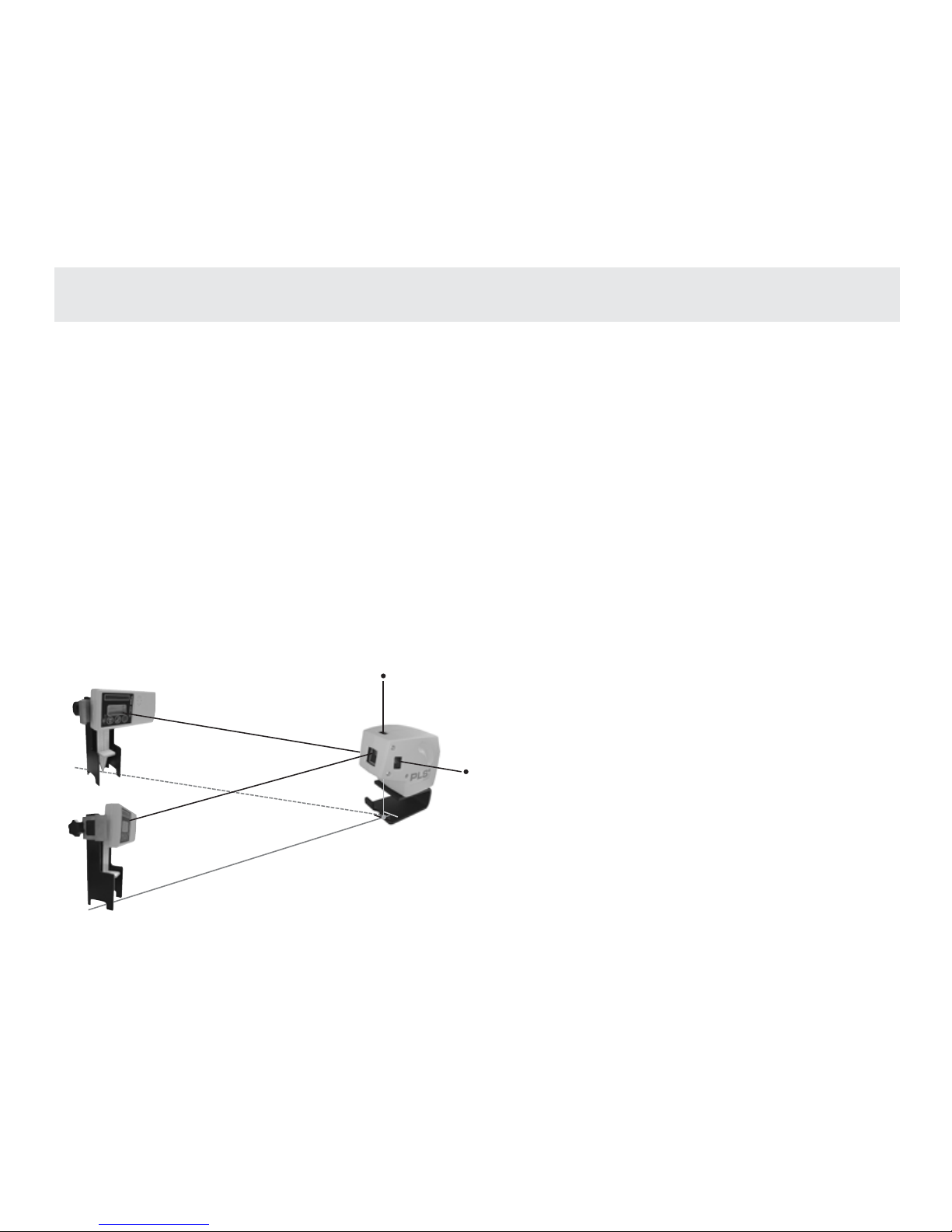
PLS5 Ext er ior Appl icat ions
15
CONCRETE CONSTRUCTION
• Layout of batter boards
• Layout & alignment for masonry projects
• Layout for saw cutting (control joints)
• Alignment of anchor & J bolts
• Layout & alignment of piers and
column footings
• Layout of form boards for concrete
flatwork
ELECTRICAL AND MECHANICAL
CONSTRUCTION
• Rough-in of conduit
• Rough-in of waste and supply lines
• Rough-in of natural gas supply lines
FRAMING CONSTRUCTION
• Layout of control lines on concrete
slabs, decking and sub-floors
• Alignment of exterior heavy gauge
steel framing
• Layout & alignment for commercial &
residential wood framing
GLAZING CONSTRUCTION
• Layout & install of curtain walls &
storefront projects.
“Beep Beep”
“Beep Beep”
Page 19

Specif icat ions
PLS
5
PLS
3
Light Source: Semiconductor laser diode Semiconductor laser diode
630-650nM, visible 630-650nM, visible
Working range: +/- 100 feet +/-100 feet
Accuracy: < 1/8” @ 100 feet < 1/4” @ 100 feet
(<3mm @ 30 meters) (<6mm @ 30 meters)
Leveling: Automatic Automatic
Leveling range: +/- 6˚ +/- 6˚
Power supply: 3 AA batteries, alkaline or 3 AA batteries, alkaline or
Ni-cad rechargeable Ni-cad rechargeable
Operating time: + 30 hrs. continuous use + 30 hrs. continuous use
Operating temp.: 0˚ F to 122˚ F 0˚ F to 122˚ F
(-18˚ C to 50˚ C) (-18˚ C to 50˚ C)
Storage temp.: -40˚ F to 158˚ F -40˚ F to 158˚ F
(-40˚ C to 70˚ C) (-40˚ C to 70˚ C)
Indicators: Green light: ON Green light: ON
Red light: EXCEEDS Red light: EXCEEDS
TILT TILT
Amber light: BATTERY Amber light: BATTERY
LOW LOW
Environmental: Water resistant; not Water resistant; not
submersible submersible
Dimensions: 2” X 4” X 4 3⁄4 “ 1 3/4” x 5” x 3 1/4”
Weight (with batteries): 1.13 lbs. ( .52 kg. ) 12 oz. (.33 kg.)
16
Page 20

PLS La b Technicia ns
PLS• Paci f i c Laser Syst ems
2550 Ker ner Bl vd., San Raf ael , CA 94901
www.pl sl aser .com • 800 601 4500
 Loading...