

PLP Bushranger Edger Owner's Manual


2
Copyright © Roy Gripske & Sons Pty. Ltd. 2012
SAFETY AWARENESS
Whenever you see the symbols shown below, heed their instructions! Always follow safe operating and
maintenance practices.
WARNING
This warning symbol identifi es special instructions or procedures which, if not correctly followed, could
result in personal injury, or loss of life.
This caution symbol identifi es special instructions or procedures which, if not strictly observed, could
result in damage to, or destruction of equipment.
NOTE
lndicates points of particular interest for more effi cient and convenient operation.
FOREWORD
We wish to thank you for choosing this Bushranger Edger. Read this Owner’s Manual carefully before
operating, as it contains information which will be of value in obtaining maximum service from your
Bushranger Edger. All information, illustrations and specifi cations in this manual are based on the latest
production information available at the time of publication.
The right is reserved to make changes at any time without notice.
NOTE
WARNING
CAUTION
»»»»»»»»»»»»»»» TABLE OF CONTENTS «««««««««««««««
Specifi cations ............................................................................................................. 4
Serial Number Locations .............................................................................................. 4
Location of Parts.........................................................................................................4
Operation .................................................................................................................. 5
Starting Engine .......................................................................................................... 5
Stopping Engine .........................................................................................................5
Engaging Blade .......................................................................................................... 5
Adjusting Cutting Depth .............................................................................................. 6
Adjusting Curb Height ................................................................................................. 6
Adjusting Blade Angle ................................................................................................. 6
Fuel ..........................................................................................................................6
Engine Oil .................................................................................................................. 6
Maintenance and Adjustment ...................................................................................... 7
Periodic Maintenance Chart .........................................................................................7
Blade Nut and Engine Mounting Nuts ............................................................................. 8
Engine Cooling Fins ..................................................................................................... 8
Air Cleaner ................................................................................................................ 8
Depth Adjustment Pins ................................................................................................ 8
Blade Arm ................................................................................................................. 8
Blade ........................................................................................................................ 9
Spark Plug ................................................................................................................. 9
Engine Oil ................................................................................................................. 9
Drive Belt .................................................................................................................10
Troubleshooting .......................................................................................................... 11
Storage ..................................................................................................................... 12
Assembly .................................................................................................................. 12

3
Copyright © Roy Gripske & Sons Pty. Ltd. 2012
Safety Tips Operate safely: Service safely:
Wear Protective Clothing
Avoid Rotating Blade
Avoid Injury From
Thrown Objects
READ THIS FIRST
Read and understand
all safety tips before
using edger. Before you
operate:
Remove all debris that
might wrap around blade
shaft.
Remove objects that
might be thrown by
edger.
WARNING WARNING WARNING
WARNING
Wear close fi tting
clothing and safety
equipment appropriate
to the job. Prolonged
exposure to loud noise
can cause impairment
or loss of hearing.
Wear a suitable hearing
protective device
such as earmuffs or
earplugs to protect
against objectionable
or uncomfortable loud
noises.
Do not put hands or feet
under or into edger when
engine is running.
Do not adjust cutting
angle or level while
blade is turning.
WARNING
WARNING
Do not let anyone
operate edger without
proper instruction.
Keep people and pets
away from edging area.
Operate only in daylight.
Do not put hands or feet
near or under blade.
Do not operate when
barefoot or wearing
sandals. Wear protective
footwear.
Be sure of your footing
Keep a fi rm hold on
handgrips. Walk-do not
run.
Disengage blade before
starting engine.
Do not run engine
indoors.
Push-do not pull edger.
Do not use edger as a
lawn mower. Do not lift
edger when engine is
running.
Do not use edger unless
all guards are in place.
Do not touch muffl er or
other hot parts.
Wear protective eye and
footwear while operating
edger.
Avoid loss of control
or tipping on slopes
and sharp corners by
reducing ground speed.
Stay alert for uneven
sidewalks, holes in
terrain or other hazards
If you hit an object,
stop engine. Fix damage
before you operate
again.
Adjust blade angle and
set wheel spacing only
after you stop engine
and disengage blade.
Keep all parts in good
condition and fastened in
place.
Unauthorized
modifi cations to edger
may impair the functions
and/or safety and affect
edger life.
Before you service, clean
or inspect edger:
Stop engine.
Let engine cool.
Keep children, pets and
bystanders awayfrom
cutting area.
Pick up objects that may
be thrown by blade.
when edging.
4
Copyright © Roy Gripske & Sons Pty. Ltd. 2012
»»»»»»»»»»»»»»»»»SPECIFICATIONS«««««««««««««««««
ENGINE
Type
Displacement
Bore x Stroke
Maximum Horsepower
Air Cleaner
Ignition
Spark Plug
Lubrication System
Engine Oil Capacity
Fuel Tank Capacity
DIMENSIONS
Overall Length
Overall Width
Overall Height
Weight
Forced air-cooled, horizontal shaft 4-stroke OHV Single Cylinder
Gasoline Engine
56 x 40 mm
2.2 kw (3 hp) /3600 rpm
3600 r/min (rpm)
Dual elements
Solid State Ignition
NGK BR6HS
Splash
0.41 L
1.8 L
1210 mm
474mm
864mm
30 kg
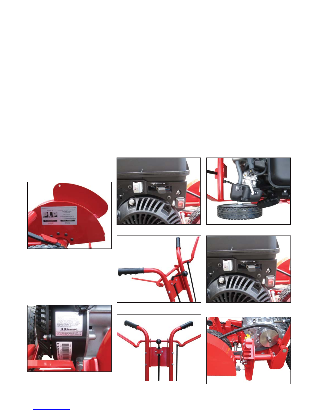
SERIAL NUMBER LOCATION
ENGINE NUMBER LOCATION
The serial number of the
Bushranger Edger is located on
the outer face of the edger blade
cover
A. Frame Number
A.
E
F
Engine No.
The Engine Number of the
Bushranger Edger is located on
the side face of the fanhousing
A. Engine Number
LOCATION OF PARTS
A. Ignition Switch D. Choke Rod
Specifi cations subject to change without notice.
B. Blade Engagement Lever
C. Cutting Depth & Curb Wheel
Control
E. Engine/Blade Control Lever
Speed Control
F. Blade Angle Lever Curb Wheel
Control
A
A
C
B
D
5
Copyright © Roy Gripske & Sons Pty. Ltd. 2012
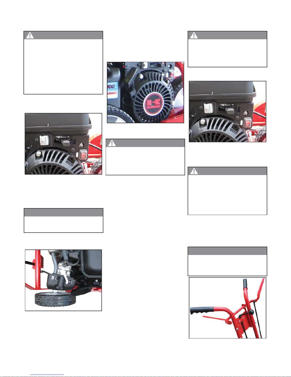
OPERATION
Starting engine
• With clutch/blade control lever
in DISENGAGED position, move
ignition switch to RUN.
A. Ignition Switch
B. Engine/Blade Control Lever
Speed Control
• Put engine speed control in
mid-throttle position.
• Pull choke rod to CLOSE
position to start a cold engine.
A. Choke Rod
• Pull recoil starter handle slowly
until you feel resistance, then pull
fast and steady.
• Use short pulls: one-half to
two-thirds of rope length.
Do not allow rope to
snap back by itself. This
may damage rope or
starter.
• Let rope recoil slowly when
engine starts.
• Push choke rod across
• Warm engine at fast idle for 1
to 2 minutes.
Stopping Engine
• Move ignition switch to the OFF
position.
A . Ignition Switch
Engaging Blade
• Move clutch/blade control lever
toward handle grip. When held
tight against handle, blade is fully
engaged.
A. Clutch/Blade Control Lever
Start engine with clutch/
blade control lever in the
DISENGAGED position.
Do not run engine in an
enclosed area.
Check blade position
so it will not strike any
objects.
WARNING
A
B
Do not choke a warm
engine.
NOTE
Blade speed is increased
when engine speed is
increased.
NOTE
.
A
CAUTION
A. Recoil Starter Handle
Before stopping engine,
put clutch/blade control
lever in the DISENGAGED
position.
CAUTION
A
Blade will begin to turn
when lever is moved
toward handle grip. Keep
people and pets away
from blade when starting
edger.
WARNING
A
A
 Loading...