

PLP BCH25, BCH35, BCH25H, BCH35H Operator's Manual

String Trimmer
BCH25, BCH35
Brushcutter
BCH25H, BCH35H
Owner’s/Operator’s Manual
Completely read and understand this manual before using this product.

Foreword
This Owner’s/ Operator’s Manual is designed to familiarize the operator with the various features and
component parts of the equipment and to assist you with the assembly, operation and maintenance
of your new Trimmer/ Brushcutter.
It is essential that any operator of this Trimmer/ Brushcutter reads and understands the contents this
manual before using the Trimmer/ Brushcutter.
For additional assistance, contact any local authorized PLP dealer.
Contents
Page
Foreword
……………………………………………………………………………………………… 1
Safety Instructions
…………………………………………………………………………………… 2
Operator Safety
………………………………………………………………………………… 2
Trimmer/Brushcutter Safety
……………………………………………………………………… 2
Fuel Safety
………………………………………………………………………………………… 2
Trimmer/Brushcutter Operating Safety
………………………………………………………… 3
Safety and Instruction Decals
…………………………………………………………………… 4
Product Description
…………………………………………………………………………………… 4
Assembly
……………………………………………………………………………………………… 5
Assembling Engine and Drive Shaft Assembly
………………………………………………… 5
Handle Installation
………………………………………………………………………………… 5
Connecting Throttle Cable
……………………………………………………………………… 6
Connecting Stop Switch wires
…………………………………………………………………… 6
Installing Guard
…………………………………………………………………………………… 6
Installing Cutting Attachments
…………………………………………………………………… 7
Attaching Shoulder Harness/ Strap
…………………………………………………………… 8
Before Operation
…………………………………………………………………………………… 8
Oil and Fuel
……………………………………………………………………………………… 8
Starting and Stopping
…………………………………………………………………………… 9
Idle Speed Adjustment
…………………………………………………………………………… 9
Trimmer Operation
………………………………………………………………………………… 10
Trimmer Operating Position
…………………………………………………………………… 10
Cutting with Nylon Trimmer Line
……………………………………………………………… 11
Brushcutter Operation
……………………………………………………………………………… 12
Brushcutter Operating Position
………………………………………………………………… 12
Cutting Direction
………………………………………………………………………………… 13
Cutting Blades
…………………………………………………………………………………… 14
Maintenance
………………………………………………………………………………………… 14
Gearcase
………………………………………………………………………………………… 14
General Cleaning and Tightening
……………………………………………………………… 14
Blade Sharpening
………………………………………………………………………………… 15
Storage
………………………………………………………………………………………………… 15
Troubleshooting
……………………………………………………………………………………… 15
Specifications
………………………………………………………………………………………… 16
─1─

Safety Instructions
The warning system in This manual identifies potential hazards and has special safety messages
that help you and others avoid personal injury, even death.
, and are signal words to identify the level of
hazard.
: signals an extreme hazard that will cause serious injury or death if the
recommended precautions are not followed.
: signals a hazard that may cause serious injury or death if the recommended
precautions are not followed.
: signals a hazard that may cause minor or moderate injury if the recommended
precautions are not followed. Two other words are also used to highlight
information. “Important” calls attention to special mechanical information and
“Note” emphasizes general information worthy of special attention.
Operator safety
1. Read and understand this Manual before using the Trimmer/ Brushcutter. Be thoroughly familiar
with the proper use of this Trimmer/ Brushcutter.
2. Always wear eye protection and hearing protection.
3. Always wear heavy long pants, a long sleeved shirt, boots and gloves. Do not wear loose clothing,
jewelry, short pants, sandals, or go barefoot. Secure hair so it is above shoulder length.
4. Never operate this Trimmer/ Brushcutter when you are tired, ill, or under the influence of alcohol,
drugs or medication.
5. Never start or run the engine inside a closed room or building. Breathing exhaust fumes can
cause death.
6. Keep the grip of handles clean of oil, fuel and dirt.
Trimmer/ Brushcutter safety
1.Shut off the engine and be certain the cutting attachment has completely stopped rotating before
inverting the Trimmer/ Brushcutter, performing maintenance on or working on the machine.
2. Make sure the Trimmer/ Brushcutter is assembled correctly and that the cutting attachment is
correctly installed and securely fastened as instructed in the Assembly section.
3.Inspect the Trimmer/ Brushcutter before each use. Replace damaged parts. Check for fuel leaks.
Make sure all fasteners are in place and tightened securely. Follow the maintenance instructions
beginning on page 14.
4. Make sure the cutting attachment does not rotate at engine idle speed. Refer to Idle Speed
Adjustment, page 9.
5.Inspect the cutting attachment and replace any parts that are cracked, chipped or damaged before
using the Trimmer/ Brushcutter.
6. Make sure the cutting attachment blade is installed and positioned correctly before using the
Trimmer/ Brushcutter.
7. Never use a cutting attachment or replacement parts that are not approved by PLP.
8. Maintain the Trimmer/ Brushcutter according to the recommended maintenance intervals and
procedures in the Maintenance section beginning on page 14.
9. If running problems or excessive vibration occur, stop immediately and inspect the unit for the
cause. If the cause cannot be determined or is beyond your ability to correct, return the Trimmer/
Brushcutter to your servicing PLP dealer for repair.
Fuel safety
1. Gasoline is highly flammable and must be handled and stored carefully. Use a container approved
for fuel for storing gasoline.
2. Pour fuel outdoors and where there are no sparks or flames.
3. Do not smoke near fuel or Trimmer/ Brushcutter, or while using the Trimmer/ Brushcutter.
CAUTION WARNING
DANGER
DANGER
WARNING
CAUTION
─2─

15m (50ft.)
Minimum
4. Do not overfill the fuel tank. Stop filling upper fuel level of the tank (see HONDA ENGINES Owner’
Manual).
5. Wipe up any spilled fuel before starting the engine.
6. Move the Trimmer/ Brushcutter at least 3m away from the fueling location before starting the
engine.
7. Do not remove the Trimmer/ Brushcutter fuel tank cap immediately after stopping the engine.
8. Allow the engine to cool before refueling.
9. Drain the tank and run the engine dry before storing the unit.
10. Store fuel and Trimmer/ Brushcutter away from open flame, sparks and excessive heat. Make
sure fuel vapors cannot reach sparks or open flames from water heaters, furnaces, electric motors,
etc.
Trimmer/ Brushcutter Operating safety
1. THIS TRIMMER/BRUSHCUTTER CAN CAUSE SERIOUS INJURIES. Read the instructions
carefully. Be familiar with all controls and the proper use of the Trimmer/ Brushcutter.
2. Never allow children to operate the Trimmer/ Brushcutter. It is not a toy. Never allow adults to
operate the unit without first reading this Operator’s Manual.
3. Avoid using the Trimmer/ Brushcutter near rocks, gravel, stones and similar material that would
cause harmful missiles.
4. Keep children, bystanders and animals outside
a15m (50ft.) radius from the operator and
Trimmer/ Brushcutter.
5. If you are approached while operating the
Trimmer/ Brushcutter, stop the engine and
cutting attachment rotation.
6. Use the Trimmer/ Brushcutter only in daylight or good artificial light.
7. Never operate the Trimmer/ Brushcutter without proper guards in place.
8. Do not put hands or feet near or under any rotating parts. Keep clear at all times. Keep all parts of
your body away from the rotating cutting attachment and hot surfaces such as the muffler.
9. When cutting heavy brush or small trees, always swing the Brushcutter from right to left to prevent
kick-back.
10. Keep a firm footing and balance. Do not overreach.
11. Use the right tool for the job. Do not use the Trimmer/ Brushcutter for any job that is not
recommended by PLP.
─3─
CORRECT
Direction of
Swing
No Kick-back
Zone
INCORRECT
Direction of
Swin
g
DANGER
Kick-back Zone
Safety and Instruction Decals
Safety decals and instructions are easily visible to the operator and are located near any area of
potential danger. Replace any that are damaged or lost.
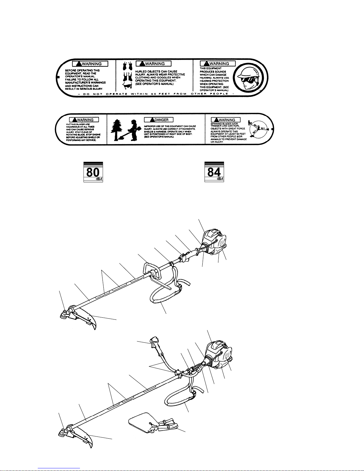
Product Description
ON SHAFT
(
Part No. 221501
)
ON SHAFT (Part No. 221502
)
─4─
2
1
9
8
3
7
4
5
6
10
17
11
13
12
14
1. Gearcase
2. Shaft Assembly
3. Safety and Instruction
Decals
4. Model Name
5. Loop Handle
6. Attachment Ring for
Shoulder Hanging Strap
7. Throttle Trigger and
Stop Switch
8. Shaft Grip
9. Clutch Drum Housing
10. Engine
11. Air Filter
12. Fuel Tank
13. Throttle Cable and Stop
Switch Wires
14. Strap
15. Handle Grip
16. Horn Handle
17. Blade Guard
18. Shoulder Harness
BCH25, BCH35
2
9
17
16
3
7
4
8
6
10
11
13
15
12
14
(
BCH25H
)
1
18 (BCH35H
)
BCH25H, BCH35H
[BCH25, BCH25H] ON ENGINE
(
Part No. 223075
)
Sound pressure
level 80dB
(A)
[BCH35, BCH35H] ON ENGINE
(
Part No. 227026
)
Sound pressure
level 84dB
(A)
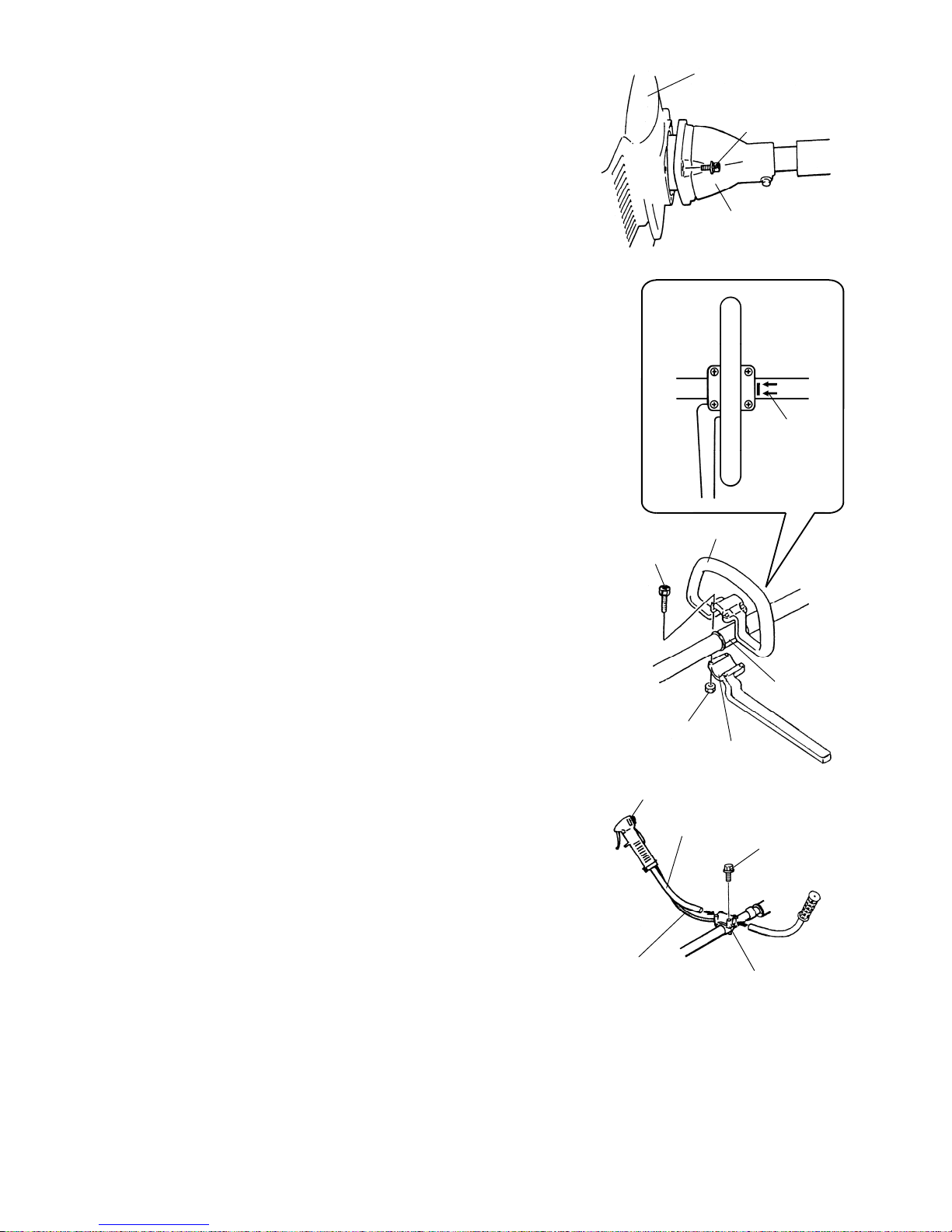
Assembly
Assembling Engine and Drive Shaft Assembly
Attach the clutch drum housing to the engine using the four
screws supplied with the unit.
Handle Installation
LOOP HANDLE
Loop handle must be assembled gearcase side from the
arrow (A).
【MODEL: BCH25】
1. Slip the rubber sleeve around the shaft.
2. Place the loop handle and the bottom clamp over the rubber
sleeve.
3. Install the four screws and nuts. Tighten the screws evenly.
【MODEL: BCH35】
1. Place the loop handle and the bottom clamp onto the shaft.
2. Install the four screws and nuts. Tighten the screws evenly.
HORN HANDLE
【MODEL: BCH25H and BCH35H】
IMPORTANT: Be careful not to damage the throttle cable
and stop switch wires when you remove the horn handles
from the carton.
1. Loosen the four screws on the top of the clamp bracket.
2. Insert the left and right horn handles into the clamp bracket.
Note that the horn handle with the throttle trigger and stop
switch goes on the right-hand side of the brushcutter.
3. Adjust the horn handles to the desired position, then tighten
the four screws.
─5─
Engine
Screw (4
)
Clutch Drum Housin
g
A
Loop Handle
Screw (4
)
Rubber
Sleeve
(BCH25)
Bottom Clam
p
Nut
Throttle Trigger and Stop Switch
Stop Switch Wires
and Throttle Cable
Screw (4
)
Horn Handle
Clamp Bracket
 Loading...