

Plockmatic Bm 2000 Service Manual

Provided By
http://www.MyBinding.com
http://www.MyBindingBlog.com
Plockmatic BM 2000
Booklet Maker
Service Manual 1

BOOKLET MAKER BM 2000
SERVICE MANUAL
This manual applies to the BM 2000 both in left and right version.
Within this document, all references to right version also apply to the left version
unless specially mentioned.
The difference is basically that the two models are mirrored. All pictures within this manual are of
the right version.
Due to the mirroring, typical Front and Rear designations which normally is viewed from the operator location has been replaced by Left and Right. Left and Right is viewed from the paper direction.
Clearication:
Left = Rear for right version & Front for left version
Right = Front for right & Rear for left
20 September 2006, Rev 0.01
Subject to change

Page intentionally blank

III
IMPORTANT SAFETY NOTICES
1. Before disassembling or assembling parts of the Booklet maker and peripherals.
make sure that the Booklet maker power cord is unplugged,
2. The wall outlet should be near the Booklet maker and easily accessible.
3. Note that some components of the Booklet maker and peripherals are supplied
with electrical voltage even if the main power switch is turned off.
4. If
any adjustment or operation check has to be made with exterior covers off or
open while the main switch is turned on, keep hands away from electrical or
mechanically driven components.
OBSER
VANCE OF ELECTRICAL SAFETY STANDARDS
1. The Booklet maker
and its peripherals must be installed and maintained by a
cust
omer service representative who has completed the training course on those
models.
Always connect the equipment to a properly grounded power source. In doubt, have
the power source checked by a qualied
electrician.
WARNING: Improper connection of the
equipment grounding conductor can result
in electrical shock.
Always follow
all warnings marked on, or
supplied with, the equipment.
Always locate the equipment on a solid
support surface with adequate strength for
the weight of the machine.
Always exercise care in moving or relocating the equipment.
Always keep magnets and all devices with
strong magnetic eld away from the machine.
Never use a ground adapter plug to connect the equipment to a power source that
lacks a ground connection terminal.
Never attempt any maintenance function
that is not specifically described in this
documentation.
Never remove the covers or guards that
are fastened with screws, unless you are a
trained Service representative.
Never install the unit near a radiator or any
other heat source.
Never override or “cheat” electrical or mechanical interlock devices.
Never operate the equipment if you notice
unusual noises or odors. Disconnect the
power cord from the power source and call
your customer service engineer to correct
the problem.
PREVENTION OF PHYSICAL INJURY
SAFETY AND ECOLOGICAL NOTES FOR DISPOSAL
1. Dispose of replaced parts in accordance with local regulations.

Page intentionally blank

V
TABLE OF CONTENTS
1 INSTALLATION PROCEDURE
BOOKLET MAKER BM 2000BOOKLET TRIMMER FTR 2000SQUARE
FOLDER MODULE SQF 2000 ...................................................................1-1
1.1 INSTALLATION REQUIREMENTS ..........................................................1-1
1.1.1 MINIMUM SPACE REQUIREMENTS .............................................1-1
1.1.2 POWER REQUIREMENTS .............................................................1-2
1.2 INSTALLATION FLOW CHART ...............................................................1-3
1.2.1 INSTALLATION OF BM 2000 ............................................................1-3
1.2.2 INSTALLATION OF BM 2000 AND FTR 2000 ...................................1-4
1.2.3 INSTALLATION OF BM 2000, FTR 2000 ANDSQF 2000 .................1-5
1.3 BOOKLET MAKER INSTALLATION ........................................................1-7
1.3.1 ACCESSORY CHECK ....................................................................1-7
1.3.2 INSTALLATION PROCEDURE .......................................................1-8
1.3.3 ADJUSTMENTS ............................................................................1-17
1.3.4 CONNECTORS .............................................................................1-19
1.3.5 CHECK THE INSTALLATION .......................................................1-20
1.3.6 SYSTEM SETUP .............................................................................1-21
1.4 BOOKLET TRIMMER INSTALLATION .................................................1-23
1.4.1 ACCESSORY CHECK ..................................................................1-23
1.4.2 INSTALLATION PROCEDURE .....................................................1-24
1.4.3 ADJUSTMENTS ............................................................................1-26
1.4.4 DOCKING .......................................................................................1-28
1.4.5 CONNECTORS .............................................................................1-30
1.4.6 CHECK THE INSTALLATION .......................................................1-31
1.5 SQUARE FOLDER MODULE INSTALLATION......................................1-33
1.5.1 ACCESSORY CHECK ..................................................................1-33
1.5.2 INSTALLATION PROCEDURE .....................................................1-34
1.5.2.2 Belt Stacker ..................................................................................1-35
1.5.3 ADJUSTMENTS ............................................................................1-37
1.5.4 DOCKING .......................................................................................1-39
1.5.5 CONNECTORS .............................................................................1-40
1.5.6 CHECK THE INSTALLATION .......................................................1-41
2. PREVENTIVE MAINTENANCE SCHEDULE
2.1 PM TABLE ...............................................................................................2-1
3. REPLACEMENT AND ADJUSTMENT
3.1 GENERAL CAUTIONS ............................................................................3-1
3.2 SPECIAL TOOLS AND LUBRICANTS ....................................................3-3
3.2.1 SPECIAL TOOLS ............................................................................3-3
3.2.2 REQUIRED TOOLS ........................................................................3-4
3.2.3 SYMBOLS USED IN TEXT .............................................................3-4
3.3 COVERS ..................................................................................................3-5
3.3.1 FRONT COVER ..............................................................................3-5
3.3.2 REAR COVER ................................................................................3-6
3.3.3 INFEED COVER .............................................................................3-7
3.3.4 OUTFEED COVER .........................................................................3-8

VI
3.3.5 BELT STACKER ..............................................................................3-9
3.3.6 PAPER PATH ................................................................................3-10
3.4 MAIN ASSEMBLIES ..............................................................................3-11
3.4.1 INFEED MODULE ......................................................................... 3-11
3.4.2 INFEED BELT ...............................................................................3-12
3.4.3 INFEED ROLLER SHAFT .............................................................3-13
3.4.4 INFEED IDLER ARM ASSEMBLY .................................................3-14
3.4.5 IDLER ARM STAPLER AREA .......................................................3-15
3.4.6 STAPLER CARTRIDGE AND STAPLER HEAD ...........................3-16
3.4.7 STAPLER ASSEMBLY ..................................................................3-20
3.4.8 STAPLER DRIVE, STAPLING POSITION (LOWER) ....................3-21
3.4.9 STAPLER DRIVE, HOME POSITION (UPPER) ...........................3-22
3.4.10 CLINCHER TIMING ......................................................................3-23
3.4.11 CLINCHER HEIGHT .....................................................................3-24
3.4.12 CLINCHER ASSEMBLY ................................................................3-25
3.4.13 SIDE JOGGER DRIVE ..................................................................3-27
3.4.14 SIDE JOGGER CHANNELS .........................................................3-28
3.4.15 REAR JOGGER FINGERS ...........................................................3-31
3.4.16 REAR JOGGER ALIGNMENT ......................................................3-32
3.4.17 FOLD ROLLER, LOWER ..............................................................3-33
3.4.18 FOLD ROLLER, UPPER ...............................................................3-34
3.4.19 STOP GATE ..................................................................................3-35
3.4.20 FOLD STOP ..................................................................................3-36
3.4.21 PRE-FOLD TRANSPORT BELTS .................................................3-38
3.5 SENSORS AND SWITCHES .................................................................3-39
3.5.1 Q1 INFEED PAPER PATH ............................................................3-39
3.5.2 Q2 MANUAL FEEDING START SENSOR ....................................3-40
3.5.3 Q3 INFEED MOTOR ENCODER (M1) ..........................................3-41
3.5.4 Q4 BACK JOGGER MOTOR HOME SWITCH (M2) .....................3-42
3.5.5 Q5 BACK JOGGER POSITIONING MOTOR ENCODER (M3) ....3-43
3.5.6 Q6 SIDE JOGGER MOTOR ENCODER (M4) ..............................3-44
3.5.7 Q7 EDGE STAPLING START CYCLE SENSOR ..........................3-45
3.5.8 Q8 SIDE STAPLING START CYCLE SENSOR ............................3-46
3.5.9 Q9 STAPLE/FOLD POSITIONING MOTOR ENCODER (M6) ......3-47
3.5.10 Q10 PRE-FOLD TRANSPORT MOTOR ENCODER (M8) ............3-48
3.5.11 Q11 FOLD ROLLER MOTOR ENCODER (M9) ............................ 3-49
3.5.12 Q12 FOLD SENSOR .....................................................................3-50
3.5.13 Q13 FOLD STOP POSITIONING MOTOR ENCODER (M11) ......3-51
3.5.14 Q14 EXIT SENSOR ......................................................................3-52
3.5.15 Q15 COVER OPEN SENSOR ......................................................3-53
3.5.16 SW1 BACK JOGGER MOTOR (M11) HOME POS. SWITCH ...... 3-54
3.5.17 SW2 STAPLER MOTOR (M5) HOME POS. SWITCH .................. 3-55
3.5.18 SW4 STAPLE/FOLD POS. MOTOR (M6) HOME POS. SWITCH ...3-56
3.5.19 SW5 FOLD KNIFE MOTOR (M10) HOME POS. SWITCH ...........3-57
3.5.20 SW6 INTERLOCK CIRCUIT .............................................................3-58
3.6 MOTORS ...............................................................................................3-59
3.6.1 INFEED MOTOR M1 .....................................................................3-59
3.6.2 BACK JOGGER MOTOR M2 ........................................................3-60

VII
3.6.3 BACK JOGGER POSITIONING MOTOR M3 ...............................3-61
3.6.4 SIDE JOGGER MOTOR M4 .........................................................3-62
3.6.5 STAPLER MOTOR M5 ..................................................................3-63
3.6.6 STAPLE / FOLD POSITIONING MOTOR M6 ...............................3-64
3.6.7 STAPLED SET TRANSPORT MOTOR M7 ...................................3-65
3.6.8 PRE-FOLD TRANSPORT MOTOR M8 .........................................3-66
3.6.9 FOLD ROLLER MOTOR M9 .........................................................3-67
3.6.10 FOLD KNIFE MOTOR M10 ...........................................................3-68
3.6.11 FOLD STOP GATE MOTOR M11 .................................................3-70
3.6.12 BELT STACKER MOTOR ST-M1 ..................................................3-71
3.7 SOLENOIDS ..........................................................................................3-73
3.7.1 SOL1 EDGE STAPLING TRANSPORT SOLENOID .....................3-73
3.7.2 SOL2/SOL3 STAPLE STOP GATE SOLENOIDS .........................3-74
3.7.3 SOL4 STOP GATE SOLENOID ....................................................3-75
4. TROUBLESHOOTING
4.1 FAULT CODE DESCRIPITIONS..............................................................4-1
4.2 BLOWN FUSE CONDITIONS ...............................................................4-33
4.3 LEDS .....................................................................................................4-35
4.4 TEST POINTS .......................................................................................4-41
5. SERVICE TABLES
5.1 SERVICE PROGRAM MODE ..................................................................5-1
5.1.1 SERVICE PROGRAM MODE OPERATIONS .................................5-1
5.1.2 SERVICE PROGRAM MODE TABLES ...........................................5-4
Check Motors and function .........................................................................5-4
5.1.3 NVM RESET .................................................................................5-12
5.2 SOFTWARE DOWNLOAD ....................................................................5-13
5.2.1 Downloading to upper PCB MD6DC B in Booklet maker. .............5-13
5.2.2 Downloading to lower PCB MD6DC C in the Booklet maker. .......5-14
5.2.3 Downloading to PCB CPU in Booklet maker. ................................5-15
5.2.4 Downloading to PCB UI in the Booklet maker. ..............................5-16
5.2.5 Downloading to PCB MD6DC in Trimmer. ....................................5-17
5.2.6 Downloading to PCB MD6DC in Square Fold. ..............................5-18
5.3 SELF-DIAGNOSTIC MODE ..................................................................5-19
5.3.1 RUN TIME DIAGNOSTICS ...........................................................5-19
5.3.2 DETAILED SELF-DIAGNOSTIC MODE ........................................5-19
5.4 PAPER SIZE RESET ....................................................................5-21
5.5 SQF SERVICE .......................................................................................5-25
6. DETAILED SECTION DESCRIPTIONS
6.1 ELECTRICAL COMPONENT LIST ..........................................................6-1
6.1.1 CONNECTOR VIEW .......................................................................6-3
6.1.2 RIGHT VIEW ...................................................................................6-4
6.1.3 LEFT VIEW .....................................................................................6-5
6.1.4 OUTFEED VIEW, INNER AND LOWER .........................................6-6
6.1.5 PREFOLD TRANSPORT VIEW ......................................................6-7
6.1.6 CLINCHER AREA VIEW .................................................................6-8
6.1.7 INNER VIEW ...................................................................................6-9
6.1.8 INFEED MODULE VIEW ..............................................................6-10
6.1.9 STACKER MODULE VIEW ........................................................... 6-11

VIII
6.2 BOARD STRUCTURE ...........................................................................6-13
6.2.1 BLOCK DIAGRAM ........................................................................6-13
6.2.2
CONTROLLER CPU .....................................................................6-14
6.2.3 CONTROLLER MD6DC ................................................................
6-15
6.3 BOOKLET
MAKING PROCESS ............................................................6-17
6.3.1 PRINCIPLE OF OPERATION .......................................................6-17
6.3.2 SIZE ADJUSTMENT .....................................................................6-19
SPECIFICATIONS
MAJOR SPECIFICATIONS........................................................................Spec-1
QUALITY SPECIFICATIONS .....................................................................Spec-1
WIRING
Booklet Maker ...............................................................................................Wir-1
1-1
Installation
20 September 2006, Rev 0.01
1 INSTALLATION PROCEDURE
BOOKLET MAKER BM 2000
TRIMMER FTR 2000
SQUARE FOLDER SQF 2000
1.1 INSTALLATION REQUIREMENTS
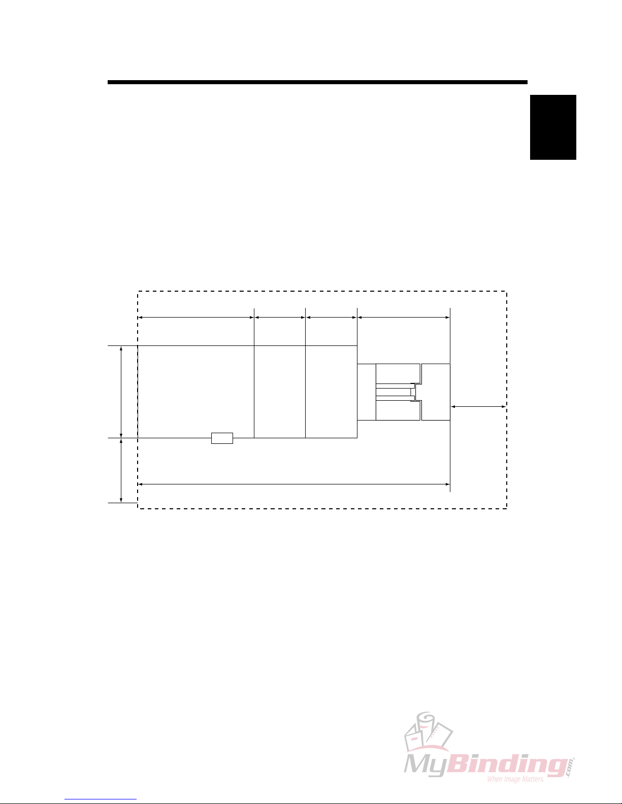
1.1.1 MINIMUM SPACE REQUIREMENTS
INSTALLATION REQUIREMENTS
SQF 2000FTR 2000BM 2000
Stacker
892 mm
35
1
/8”
360 mm
13 3/4 ”
360 mm
13 3/4 ”
645 mm
25 13/
32
”
400 mm
15
3
/4 ”
2257 mm
88
7
/8 ”
680 mm
26
25
/
32
”
555 mm
21
7
/
8
”

1-2
20 September 2006, Rev 0.01
1.1.2 POWER REQUIREMENTS
INSTALLATION REQUIREMENTS
WARNING
1. Make sure that the wall outlet is near the main machine and easily
accessible.Makesuretheplugisrmlyinsertedintheoutlet.
2. Avoid multi-wiring.
3.
Be sure to ground the machine.
1. The input voltage level and the permissible voltage uctuation are as follows:
100 V AC ± 10 %
110 V AC ± 10 %
120 V AC
+ 6 % 8 A 50-60 Hz
- 13 %
127 V AC ± 10 %
220 V AC ± 10 %
4 A 50-60 Hz
230 V AC ± 10 %
2.
Never place anything on the power cord.
1-3
Installation
20 September 2006, Rev 0.01 INSTALLATION FLOW CHART
1.2 INSTALLATION FLOW CHART
The following ow charts show how to make the installation more efcient.
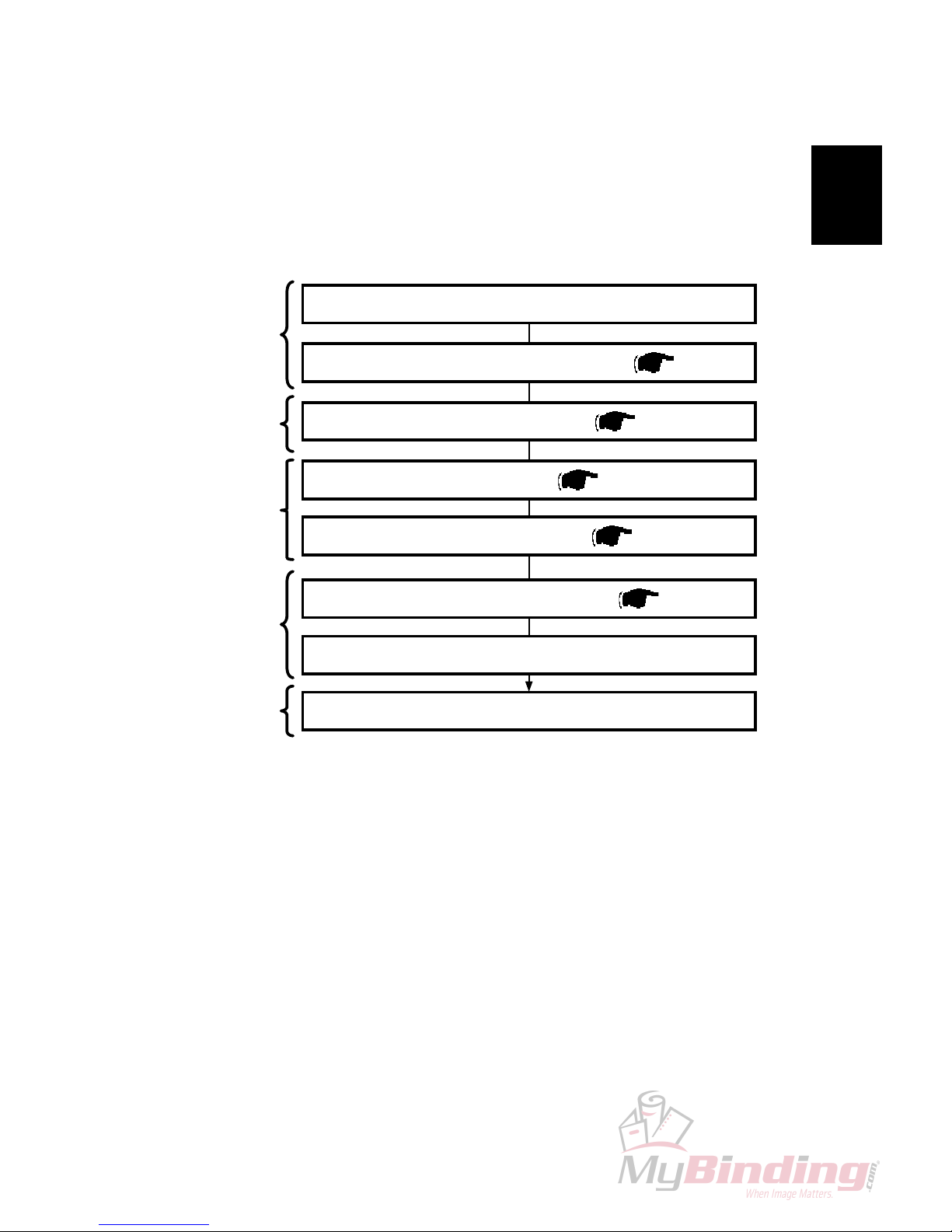
1.2.1 INSTALLATION OF BM 2000
Check the Installation
Adjust the BM 2000´s height ( 1.3.3)
Remove covers from BM 2000 ( 1.3.2.1)
Connect the cables of the BM 2000 ( 1.3.4)
Make the accessory check for BM 2000 ( 1.3.1)
Unpack BM 2000 according to unpacking procedure
FTR 2000 Trimmer: Enables On-line trimming. Especially thicker sets
( > 4 sheets) look unprofessional because of ”creep”.
FTR 2000 will trim those edges (up to 16 mm / 5/8”).
SQF 2000 Square Folder: Enables the possibility to give the booklets the
perfect bound look.
Install User Interface ( 1.3.2.2)
Step 1
Unpacking
Step 4
Electrical
connections
Step 3
Mechanical
adjustments.
Step 2
Removing
covers
Make sure to connect the Beltstacker cable to the FTR 2000
Step 5
Complete
installation
1-4
20 September 2006, Rev 0.01
INSTALLATION FLOW CHART
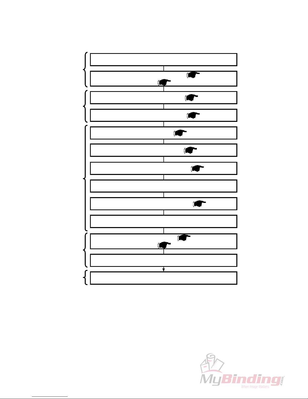
1.2.2 INSTALLATION OF BM 2000 AND FTR 2000
Check the Installation
Install the Beltstacker on FTR 2000
Dock the FTR 2000 to the BM 2000 ( 1.4.4)
Make sure the FTR 2000 is parallel to the BM 2000
Adjust the height of the FTR 2000 ( 1.4.3)
Adjust the BM 2000´s height ( 1.3.3)
Remove covers from FTR 2000 ( 1.4.2.1)
Remove covers from BM 2000 ( 1.3.2.1)
Make sure to connect the Beltstacker cable to the FTR 2000
Connect the cables of the BM 2000 ( 1.3.4) and the FTR
2000 (
1.4.5)
Make the accessory check for BM 2000 ( 1.3.1) and FTR
2000 (
1.4.1)
Unpack BM 2000 and FTR 2000
Step 1
Unpacking
Step 4
Electrical
connections
Step 3
Mechanical
adjustments
Step 2
Removing
covers
Install User Interface ( 1.3.2.2)
Step 5
Complete
installation
1-5
Installation
20 September 2006, Rev 0.01
INSTALLATION FLOW CHART
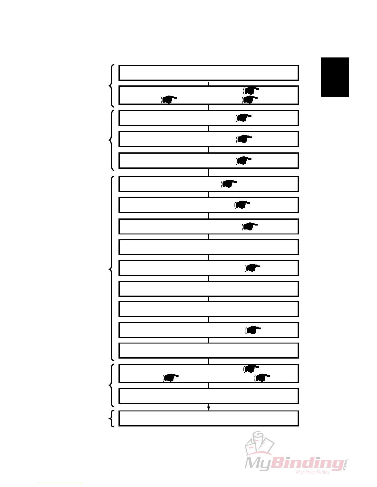
1.2.3 INSTALLATION OF BM 2000, FTR 2000 ANDSQF 2000
Check the Installation
Install the Beltstacker onSQF 2000
Make sure the FTR 2000 is parallel to theSQF 2000
Adjust the height of theSQF 2000
Dock the FTR 2000 to the BM 2000 ( 1.4.4)
Make sure the FTR 2000 is parallel to the BM 2000
Adjust the height of the FTR 2000 ( 1.4.3)
Adjust the BM 2000´s height ( 1.3.3)
Remove covers fromSQF 2000 ( 1.5.2.1)
Remove covers from FTR 2000 ( 1.4.2.1)
Remove covers from BM 2000 ( 1.3.2.1)
Make sure to connect the Beltstacker cable to theSQF 2000
Connect the cables of the BM 2000 ( 1.3.4),
FTR 2000 (
1.4.5) and theSQF 2000 ( 1.5.5)
Make the accessory check for BM 2000 ( 1.3.1), FTR
2000 (
1.4.1) andSQF 2000 ( 1.5.1)
Unpack BM 2000, FTR 2000 andSQF 2000 according to
unpacking procedure
Install User Interface ( 1.3.2.2)
Dock theSQF 2000 to the FTR 2000 ( 1.5.4)
Step 1
Unpacking
Step 4
Electrical
connections
Step 3
Mechanical
adjustments
Step 2
Removing
covers
Step 5
Complete
installation

Page intentionally blank
 Loading...