

Plockmatic BLM 35/50
Production Booklet Maker
Operator Manual
Please read this manual carefully before you use this product and keep it handy for future reference.
For safety, please follow the instructions in this manual.
Doc no: X04107E
Date: 26 June 2017

Electromagnetic compliance
This product complies with EU Standard EN 55032:2015, Class A.
Operation of this equipment in a residential environment could cause radio interference.
NOTE:
The domestic environment is an environment where the use of broadcast radio and
television receivers may be expected within a distance of 10m of the apparatus concerned.

Introduction
This manual contains instructions on the operation and maintenance of this machine. To
get maximum versatility from this machine all operators should carefully read and follow
the instructions in this manual. Keep this manual in a handy place near the machine.
Please read the Safety Information before using this machine. It contains information
related to USER SAFETY and PREVENTING EQUIPMENT PROBLEMS.
How to read this manual
Notation conventions
Whenever necessary, the following points for attention are indicated in this manual.
WARNING
Indicates a potentially hazardous situation which, if instructions are not followed,
could result in death or serious injury.
CAUTION
Indicates a potentiality hazardous situation which, if instructions are not followed, may
result in minor or moderate injury or damage to machine or property.
NOTE:
This sign refers to:
• Remarks for making the operation much easier. You get practical hints or knowledge to
assist you in the machine operation such as:
• Preparations required before operating
• How to prevent papers from being misfed or damaged
• Precautions required or actions to take after misoperation
• Limitations like numerical limits, functions that cannot be used together or conditions,
under which a particular function cannot be used or obtained.
• Information.
[ ]
Keys that appear on the machine’s display panel.

Safety Information
When using this machine, following safety precautions should always be followed.
Safety during operation
WARNING
• To avoid hazardous situations like for instance electric shock or danger while exposed
to moving, rotating or cutting devices, do not remove any covers, guards or screws
other than those specied in this manual.
• Turn off the power and disconnect the power plug (by pulling the plug, not the cable) if
any of the following conditions exists:
• You drop objects or spill something into the equipment.
• You suspect that your equipment needs service or repair.
• Your equipment’s covers has been damaged.
• You notice unusual noises or odours when operating the equipment.
• If the power cable or plug becomes worn out or otherwise damaged.
• Before cleaning and care (unless otherwise specically instructed).
• Electromagnetic compliance:
• This is a Class A product. In a domestic environment this product may cause radio
interference in which case the user may be required to take adequate measures.
• The product (System) which is connected to this machine will be class A.
General safety
WARNING
• Always connect the equipment to a properly grounded power source (wall outlet). If in
doubt, have the power source checked by a qualied electrician.
• Improper grounding of the equipment can result in electrical shock. Never connect the
machine to a power source that lacks a ground connection terminal. This machine is
destined for specic purpose only. Any use going beyond this specic purpose is regarded as beyond the determination. The manufacturer will not be liable for damages
resulting from any use beyond the determination, unallowed operation, respectively.
The user alone bears the risk.
• Do not make arbitrary changes or modications to the machine. The manufacturer will
not be liable for modications made at the machine on your own and damages resulting thereof. EC declaration of conformity and the mark CE will be invalidated, if you
make changes at the machine or at the individual components.
• Do not override or bypass electrical or mechanical interlock devices.
• The machine is to be used only by authorized and instructed persons. The responsibilities on operating the machine have to be strictly laid down and observed so that there
are no unclear competences regarding safety aspects.
• Vent holes serve for air circulation to protect the machine from overheating. Make sure
that the holes are not covered.
• Do not expose ngers or other parts of the body to moving, rotating or cutting devices
such as for instance between upper and lower trimmer knives.
• Always locate the equipment on a solid support surface with adequate strength tor the
weight of the machine.

General safety, continued
CAUTION
• The machine and its peripherals must be installed and maintained by a customer service
representative who has completed the training course on those models.
• Always follow all warnings marked on, or supplied with, the equipment.
• When you disconnect the power plug from the wall outlet, always pull the plug (not the cable).
• Disconnect the power cord before you move the machine. While moving the machine, always
exercise care and make sure that the power cord will not be damaged under the machine.
• Always contact service if relocating the equipment.
• Do not move the machine while the machine is running.
• Do not open covers while the machine is running.
• Do not switch off the power while the machine is running. Make sure the machine cycle has
ended.
• Lay the power cord in a way that nobody will stumble over it. Do not place things on the cord.
• Never attempt any maintenance function that is not specically described in this
documentation.
• Always keep magnets and all devices with strong magnetic elds away from the machine.
• If the place of installation is air-conditioned or heated, do not place the machine where it will be:
• Subject to sudden temperature changes.
• Directly exposed to cool air from an air-conditioner.
• Directly exposed to heat from a heater.
• If the machine is not used over an extended period of time it should be unplugged to prevent
damage in the case of overload.
NOTE:
• The indications like front and rear, left and right refer to the paper transport direction.
• The operator manual always has to be available at the place of use of the machine.
• In the interest of technical development the company reserves the right to make
alterations to specications without prior notice!

Page intentionally blank.

TABLE OF CONTENTS
What You Can Do With This Machine ............................................................................. 11
Guide to Components ...................................................................................................... 13
Booklet Maker ............................................................................................................................. 13
User Interface ............................................................................................................................. 16
Control Panel.........................................................................................................................................16
Options .............................................................................................................................. 19
Rotate Crease Trim Module ........................................................................................................ 19
Booklet Maker ............................................................................................................................. 24
Alive Logo..............................................................................................................................................24
Cover Feeder ........................................................................................................................................25
BookFold Module ........................................................................................................................ 26
Trimmer ....................................................................................................................................... 28
BST4000-1 Belt Stacker Module ................................................................................................ 30
BST4000-1 Principle of Operation.........................................................................................................31
1. Basics ............................................................................................... 33
Turning On / Off the Main Power ..................................................................................... 33
RCT, Booklet Maker, BookFold Module, Trimmer & BST Module ............................................... 33
Change staple cartridges and Check Stapler ................................................................ 34
Change left/right staple cartridge(s) ............................................................................................ 34
Check left/right stapler ................................................................................................................ 35
Cover Feeder..................................................................................................................... 35
Loading covers ........................................................................................................................... 35
Emptying the trim waste bin ............................................................................................ 36
Belt Stacker ....................................................................................................................... 37
Setting up Belt Stacker for right-angled mode ............................................................................ 37
Setting up Belt Stacker for straight mode ................................................................................... 38
2. Making Booklets .............................................................................. 39
Guided Start ...................................................................................................................... 39
Guided Start, step by step .......................................................................................................... 39
Changing settings ............................................................................................................ 42
General procedure ...................................................................................................................... 42
Basic settings ................................................................................................................... 42
Input Sheet Size ......................................................................................................................... 42
Selecting standard paper sizes ............................................................................................................. 42
AUTO sheet size ...................................................................................................................................43
Custom input sheet size ........................................................................................................................ 43
Finished Booklet Size ................................................................................................................. 43
Auto trimming ........................................................................................................................................ 43
Custom booklet size .............................................................................................................................. 44
Customizing settings ....................................................................................................... 45
Staple .......................................................................................................................................... 45
Selecting stapling On or Off ..................................................................................................................45
Adjusting staple position........................................................................................................................45
Fold position ............................................................................................................................... 46
Adjusting fold position ...........................................................................................................................46
Cover .......................................................................................................................................... 46
General..................................................................................................................................................46
Cover ..................................................................................................................................................... 47
Air Separation........................................................................................................................................47
Double Sheet Detection ........................................................................................................................47
Purge Cover .......................................................................................................................................... 48

BookFold ..................................................................................................................................... 48
General..................................................................................................................................................48
Selecting BookFold pressure setting ..................................................................................................... 49
Crease ........................................................................................................................................ 50
Crease Mode ......................................................................................................................................... 50
Crease position .....................................................................................................................................50
Fine-tuning booklet appearance ..................................................................................... 51
Set registration (ne adjustment) ..........................................................................................................51
Bleed Trimmer - Asymmetric Side Trim ................................................................................................. 52
Bleed Trimmer - Cover Adjust ............................................................................................................... 52
Hand-feeding ..................................................................................................................... 53
Hand feed mode ......................................................................................................................... 53
3. Tools ................................................................................................. 55
The Tools screen ......................................................................................................................... 55
Stacker full detection .................................................................................................................. 55
Units ............................................................................................................................................ 55
Software version ......................................................................................................................... 56
Paper path light ........................................................................................................................... 56
Language .................................................................................................................................... 56
Service mode .............................................................................................................................. 57
Fold delay ................................................................................................................................... 57
Sheet feeder ............................................................................................................................... 57
Auto Rotate ................................................................................................................................. 58
BookFold offset ........................................................................................................................... 58
4. Jobs .................................................................................................. 59
Handling jobs .................................................................................................................... 59
Saving a Job ............................................................................................................................... 59
Opening and handling stored Jobs ............................................................................................. 60
5. Clearing Misfeed(s) ......................................................................... 61
Clearing misfeed(s) .......................................................................................................... 61
General ....................................................................................................................................... 61
RCT Module ....................................................................................................................... 62
Clearing misfeed(s) ..................................................................................................................... 62
Infeed “A” area and exit “D” area...........................................................................................................62
Registration and creaser area ............................................................................................................... 63
Booklet Maker ................................................................................................................... 64
Clearing misfeed(s) ..................................................................................................................... 64
Inside the Booklet Maker ....................................................................................................................... 64
Clearing misfeed in infeed area.............................................................................................................65
Clearing misfeed in folder area .............................................................................................................66
Cover Feeder..................................................................................................................... 67
Clearing misfeed(s) in vertical transport area ............................................................................. 67
BookFold Module ............................................................................................................. 68
Clearing misfeed(s) ..................................................................................................................... 68
Inside the BookFold Module .................................................................................................................. 68
Trimmer .............................................................................................................................69
Clearing misfeed(s) ..................................................................................................................... 69
Clearing misfeed in input area...............................................................................................................69
Clearing misfeed in exit area ................................................................................................................. 70

Belt Stacker ....................................................................................................................... 71
Clearing misfeed(s) ..................................................................................................................... 71
Clearing misfeed on belt stacker ........................................................................................................... 71
6. Troubleshooting .............................................................................. 73
Fault codes........................................................................................................................ 73
General ....................................................................................................................................... 73
RCT fault codes .......................................................................................................................... 73
Booklet Maker fault codes .......................................................................................................... 74
Cover Feeder fault codes ........................................................................................................... 75
BookFold Module fault codes ..................................................................................................... 76
Trimmer fault codes .................................................................................................................... 77
Belt stacker fault codes ............................................................................................................... 77
General fault codes ..................................................................................................................... 78
Clear Misfeed(s) .................................................................................................................................... 78
Close cover(s) ....................................................................................................................................... 78
Empty stacker!.......................................................................................................................................78
7. REMARKS ........................................................................................ 79
Do’s And Don’ts ................................................................................................................ 79
Where to put Your Machine ............................................................................................. 80
Machine environment ................................................................................................................. 80
Power connection ....................................................................................................................... 80
Access to machine ...................................................................................................................... 81
Maintaining Your Machines ............................................................................................. 82
Cover Feeder .............................................................................................................................. 82
Cleaning feed rollers and paper separator pad ..................................................................................... 82
BookFold Module ........................................................................................................................ 83
Cleaning feed belts................................................................................................................................83
Pressure springs ...................................................................................................................................84
RCT Module ................................................................................................................................ 85
Cleaning the paper path transportation nip rollers (12x) ....................................................................... 85
Cleaning the xing rollers (3x) ............................................................................................................... 86
Cleaning the registration cross roller (4x) & friction tires (4X) ............................................................... 87
Cleaning the rotator rollers (2x) ............................................................................................................. 88
Cleaning the paper path sensors (5x) ................................................................................................... 88
Cleaning of creaser tools (2x) ...............................................................................................................90
Adjustment of Bleed Trimmer registration angle (parallel cut)............................................................... 91
Adjustment of Creaser registration angle .............................................................................................. 92
Best practices for the BLM 35/50 system....................................................................... 93
Limitations of the BLM 35/50 system ............................................................................. 94
8. Specication ................................................................................... 97
Machine Specications .................................................................................................... 97
Rotate Crease Trim Module (option) ........................................................................................... 97
Booklet Maker ............................................................................................................................. 98
Cover Feeder Module ................................................................................................................ 99
Trimmer Module .......................................................................................................................... 99
BookFold Module ..................................................................................................................... 100
BST4000-1 Belt Stacker Module .............................................................................................. 100
System Set Size Guide ............................................................................................................. 101
Cables, plugs and jumpers ....................................................................................................... 105
INDEX.................................................................................................. 106

Page intentionally blank.
10

What You Can Do With This Machine
BF50 BookFold
Module (option)
Belt Stacker
FTR50 Trimmer Module
(option)
BLM50 upgrade kit
(option) incl. Alive Logo
BLM35/50 Production
Booklet Maker
CF50 Cover Feeder
Module (option)
RCT50 Rotate Crease
Trim Module (option)
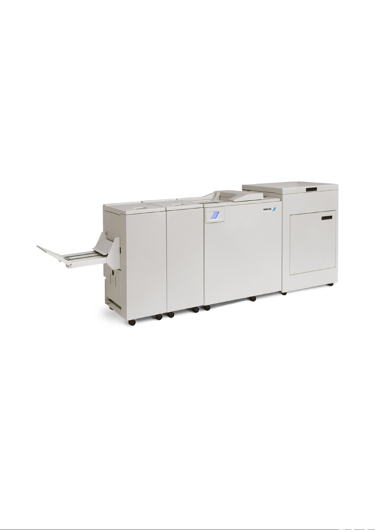
The Plockmatic BLM50 or the Plockmatic BLM35 Production Booklet Maker System
consists of:
Rotate Crease Trim Module (optional), also referred to as the RCT Module or the RCT
Cover Feeder Module (optional), also referred to as the Cover Feeder or the CF
BookFold Module (optional), also referred to as the BookFold or the BF
Trimmer Module (optional), also referred to as the Trimmer or the TR
BST4000-1 Belt Stacker Module (optional), also referred to as the BST Module or the BST
Together they form a system that allows full bleed booklet making online with the Printer.
A capacity enhancement is the BLM50 upgrade kit. This kit increases the capacity of the
BLM35 Booklet maker from 35 sheets to 50 sheets. This means that instead of 140 page
booklets, 200 page booklets are now possible. The BLM50 upgrade kit also includes the
Live logo feature. The logo below the user interface will be illuminated, allowing the user to
monitor the system status from a distance.
The print-outs rst enter the Rotate Crease Trim Module. The RCT Module is able to
rotate small(er) sheets from long edge feed to short edge feed to maintain high printer
productivity. In order to avoid toner cracking at the spine when folded, the RCT can be
programmed to crease the cover sheet. The RCT can also trim the long sides of the
booklet sheets to deliver booklets in the desired size. To enable full bleed booklets, a
Trimmer Module must be installed after the Booklet Maker, see below.
From the RCT, the printed sheets are transported into the BLM50 or BLM35 Production
Booklet Maker where they are compiled in the stapler area.
If a Cover Feeder Module is installed in the Booklet Maker, it can add any type of cover, in
colour or black and white, to the printed set. The Booklet Maker jogs and staples the set.
continued on next page
11

continued from previous page
The set is then transported further into the Booklet Maker to the folding area where the set
is folded into a booklet and delivered out to the belt stacker or a downstream module.
After the Booklet Maker, an optional BookFold Module can be attached. The stapled and
folded books will be fed into the BookFold Module where the spine of the booklets are
attened square. The booklets will now have the look of a perfect bound book. Finally, the
booklets are fed out to the optional Trimmer or directly to a Belt Stacker.
When a larger number of sheets are folded, an effect called creeping occurs. In order to
eliminate creep, an optional Trimmer Module can be attached after the Booklet Maker
or BookFold Module. The booklets are transported from the Booklet Maker or BookFold
Module into the Trimmer where the front edge will be cut off. The Trimmer combined with
an RCT Module in front of the Booklet Maker creates the possibility to create full bleed
booklets.
To allow longer, unattended runs there is an optional high capacity belt stacker available.
The BST4000-1 Belt Stacker Module will stack up to 1000 A4 or 8,5 × 11” booklets of 4
pages.
In addition to producing booklets inline, it is possible to use the Booklet Maker System for
hand-feeding.
The user interface/control panel is of
touch screen type. Point at the screen
and press the button or function you
wish to make changes to.
In this sample screen shot, the Staple
button is pressed.
A sub screen is shown.
Make your changes and conrm by
pressing the green check mark or
exit without making any changes
by pressing the red X. Pressing the
home symbol takes you back to the
main or home screen.
12
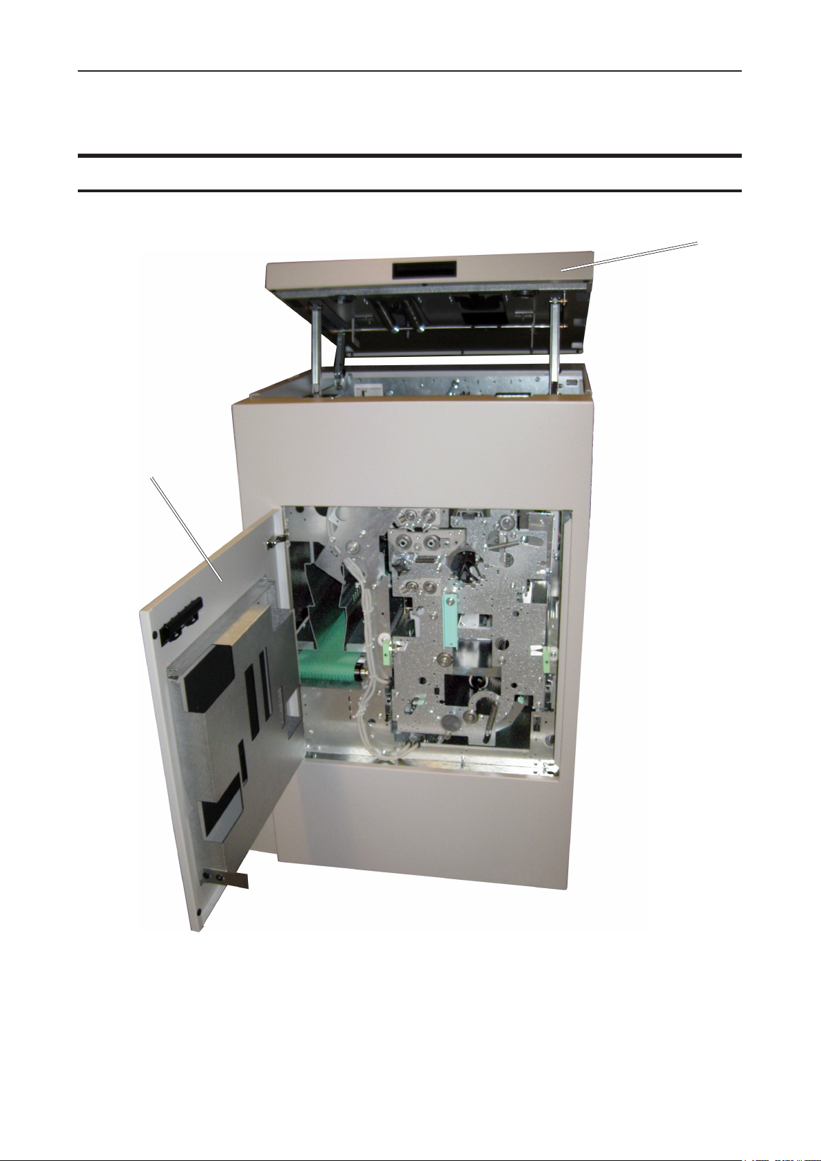
Guide to Components
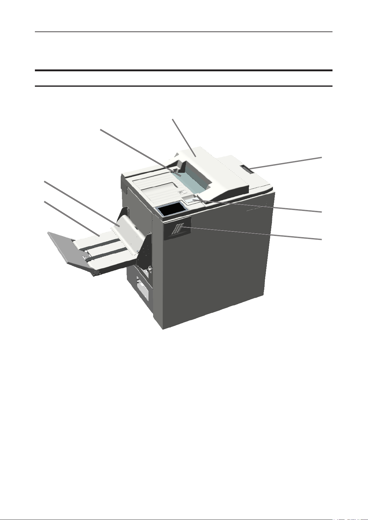
Booklet Maker
7
6
5
1
2
3
1. Top cover
2. Cover for Hand Feed
3. Latch handle
4. Live Logo, only on 50 sheet option
5. Belt Stacker
6. Belt Stacker Cover
4
7. Slot for optional Cover Feeder
13
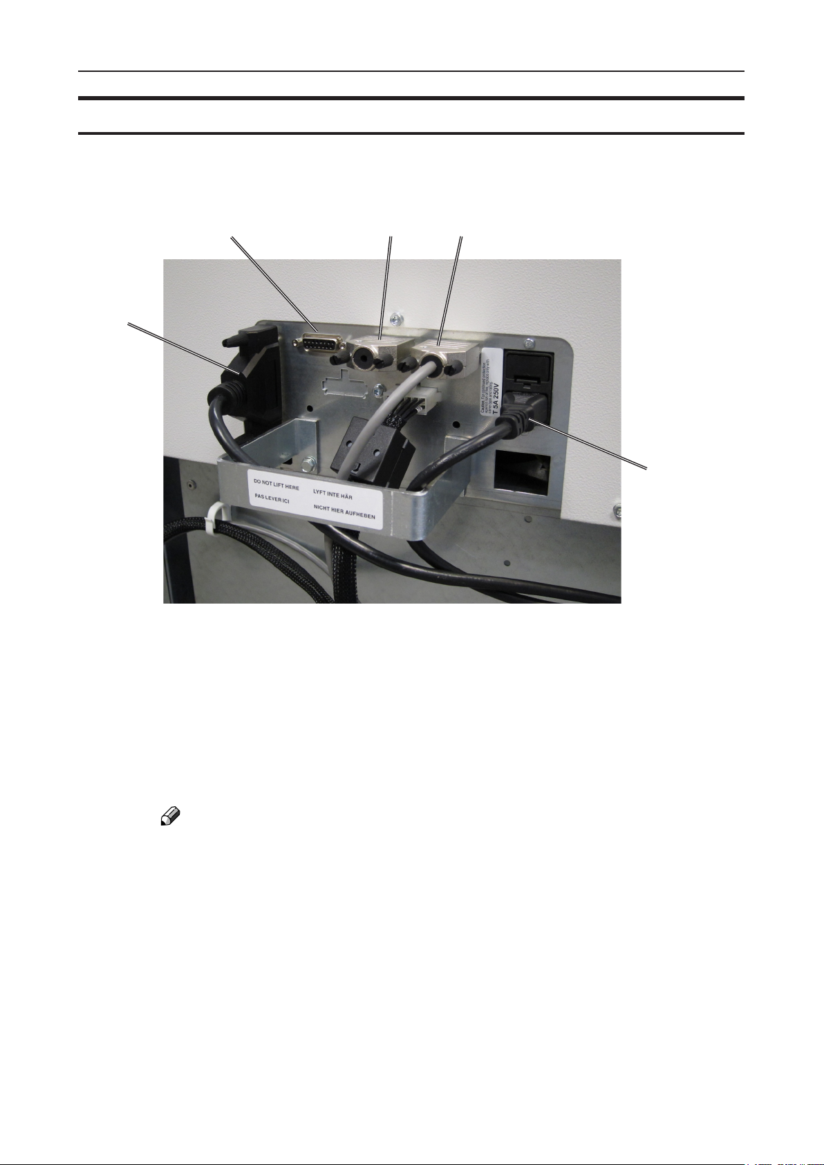
Booklet Maker, continued
1
5
2 3
4
1. Belt Stacker Connector
2. Upstreams Communication
3. Downstreams Communication
4. Power Connection
5. Printer interface
NOTE:
How to connect cables, plugs and jumpers is described at the end of this manual.
14
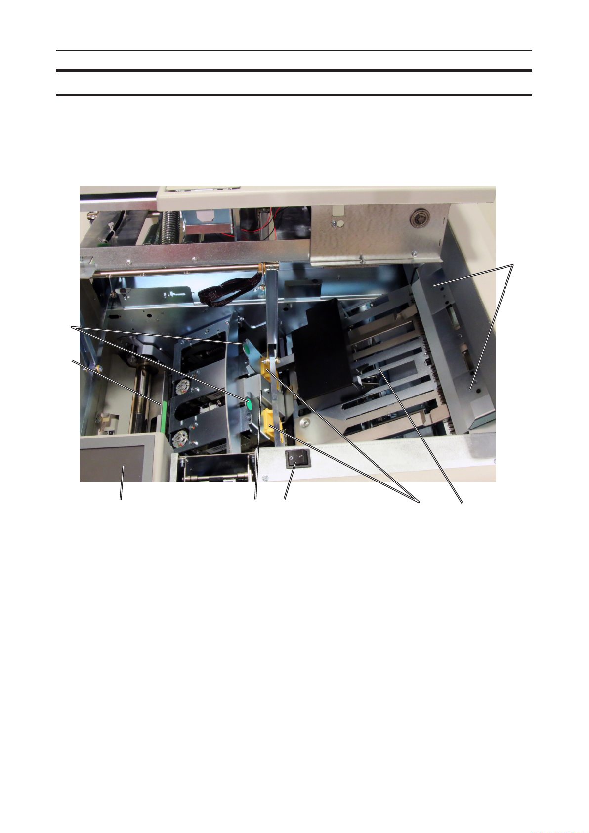
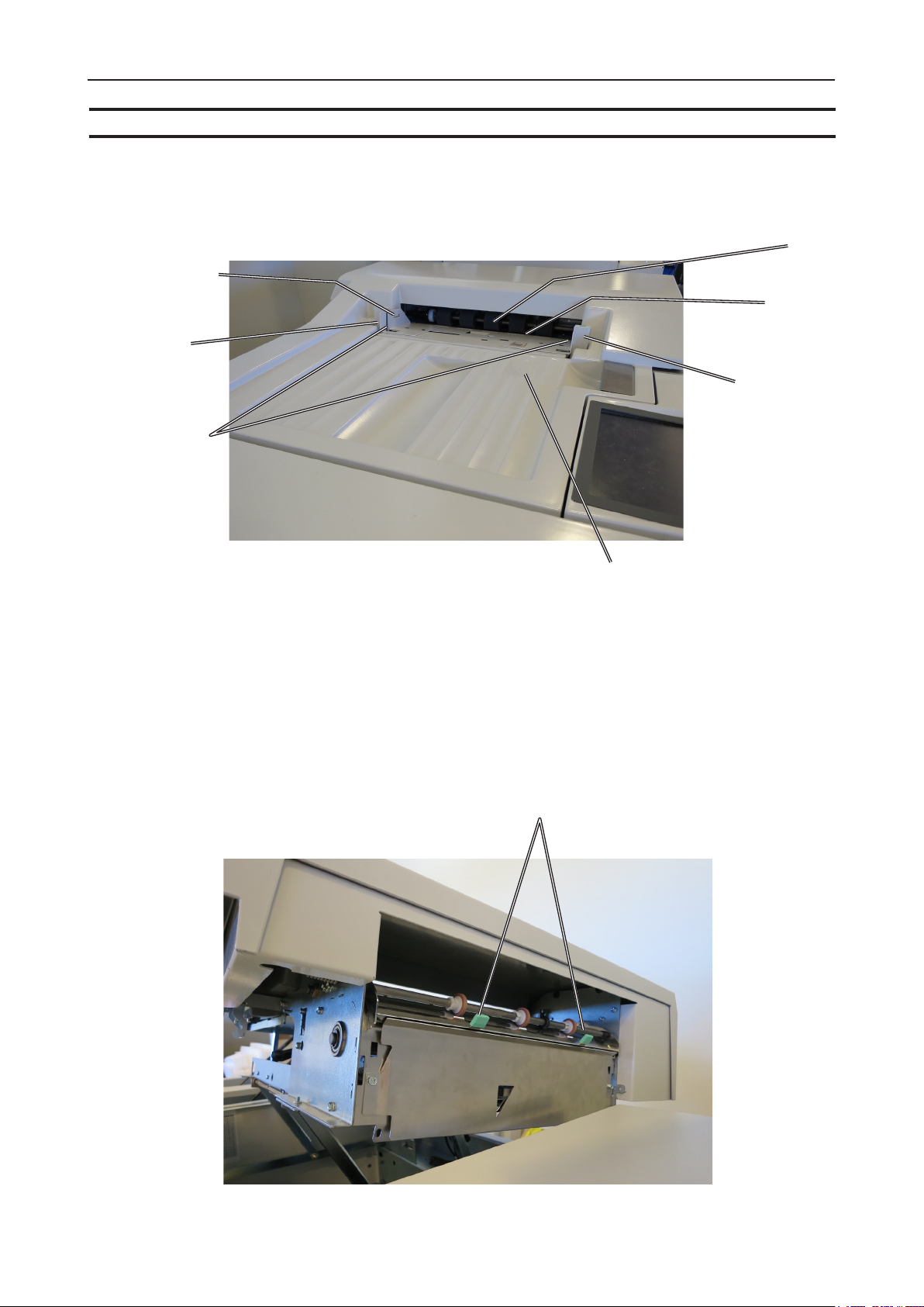
Booklet Maker, continued
Parts that are important for setup, adjustments, troubleshooting or maintenance are highlighted below.
8
7
1
1. Hand feeding paper guides
2. Compiler area
3. Staple cartridges (incl. stapler heads)
4. Main power switch
5. Set thickness sensor
6. Control panel
7. Fold roller guide
8. Staple cartridge ejection lever
23456
15
User Interface
The Plockmatic BLM50 or BLM35 Production Booklet Maker System is controlled from a panel
located on the Booklet Maker. The control panel will allow you to set up, adjust and operate the
complete system. An optional “Alive logo” makes the state of system visible from a distance.
NOTE:
Depending on modules and features installed, the screen may look different from what you
see here. Some functions are greyed out or not visible at all and remaining buttons may
stretch to t the screen. This manual will most often show a fully congured system.
Control Panel
The control panel is of touch screen type. Point at the screen and press the “button” to
reach the desired function or change the desired setting.
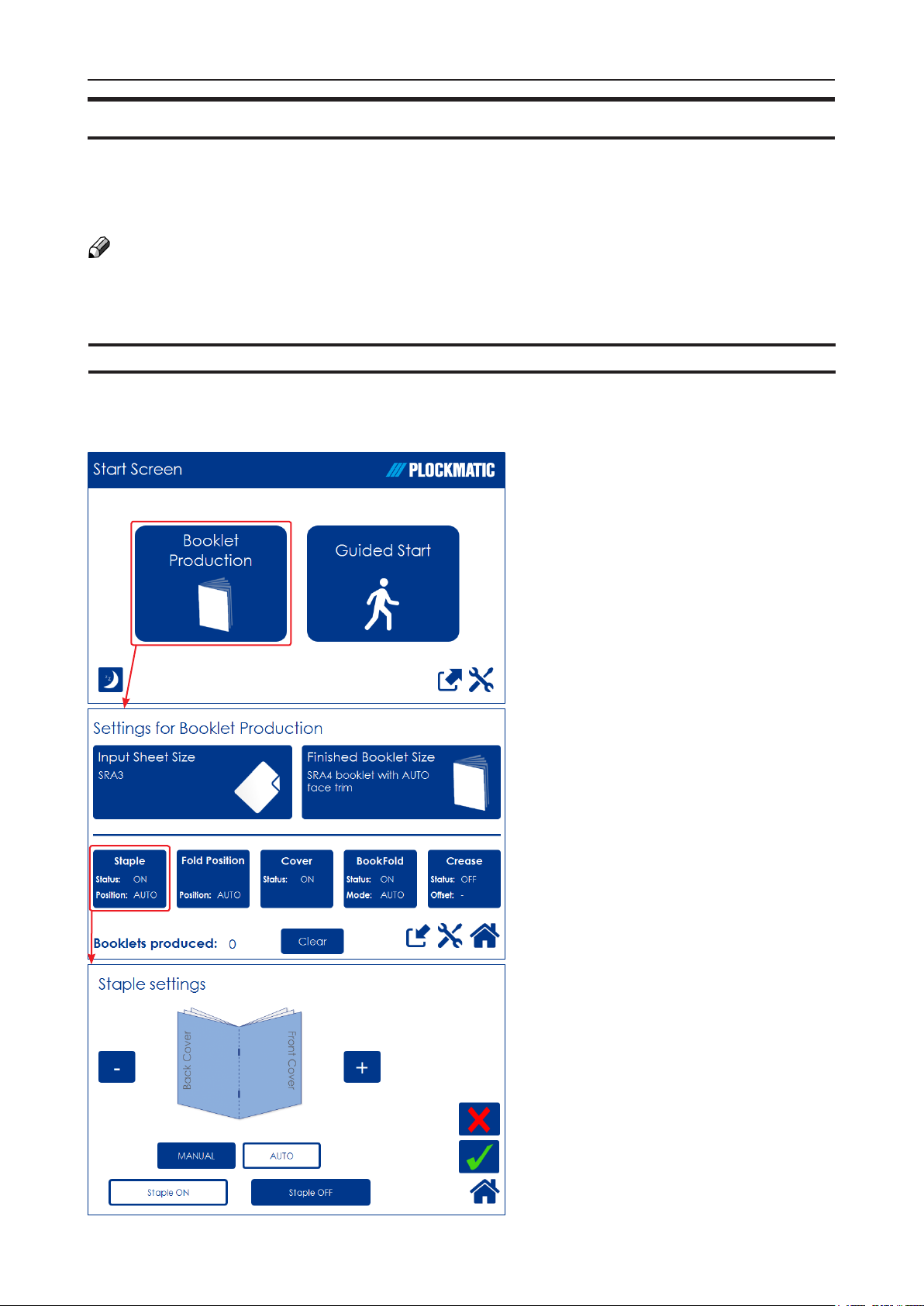
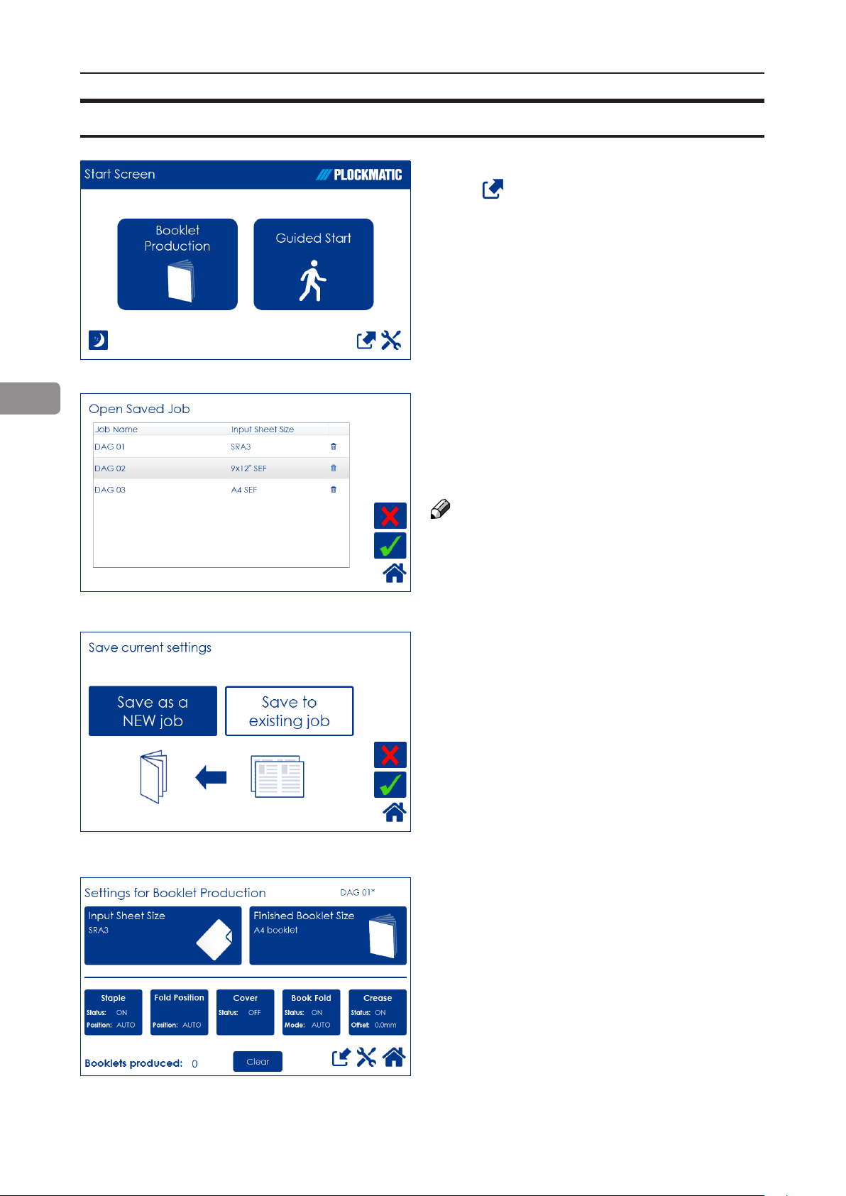
The Start Screen
When the system power is switched
on, the Start screen will be shown.
From here you can choose to set
up Booklet Production, perform a
Guided Start, retrieve stored jobs or
access the General System Settings.
Settings for Booklet Production
Pressing the [Booklet Production]
button in the Start Screen opens
the Settings for Booklet Production
screen. From here you can reach all
detailed settings for setting up the job.
A counter shows the number of
booklets produced. Clear will reset.
Detailed Settings
Pressing, for example, the [Staple]
button in the Settings for Booklet
Production screen opens the Staple
settings screen. Here you can
perform detailed settings concerning
stapling. Explore this and other
settings more thoroughly in section 2,
“Making Booklets.”
16
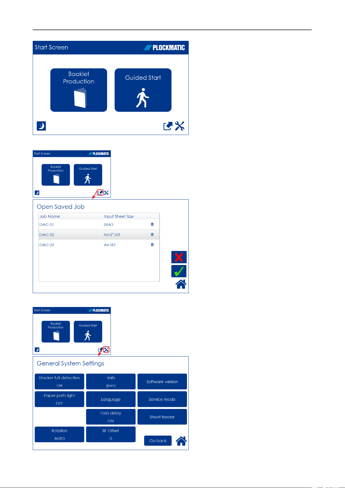
Guided Start
Guided Start is a function that takes
you through all the basic settings
the Booklet Maker System needs
for booklet production in eight easy
steps.
See “Guided Start” in section 2
“Making Booklets” for details.
The Jobs Screen
Pressing the [Open Jobs] button in
the Start screen opens the Open
saved Job screen. From here you
can open a saved job. Jobs can
be stored, deleted, customized etc.
Handling jobs is described in section
4, “Jobs”.
General System Settings
Pressing the [Tools] button opens the
General Systems Settings screen.
From here you can change basic
settings like the display language,
setting units from millimeters to
inches and more. See section 3,
”Tools” for how to work with the Tools
screen.
17
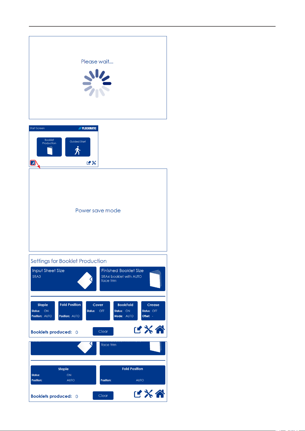
The Please wait screen
While the machine sometimes needs
time to perform changes in settings,
the Please wait screen will be shown.
Power save mode
When the Booklet Maker System is
in a ready state, it will enter power
save mode after 20 minutes of
inactivity.
To recover from Power save mode,
touch the screen or send a print job
to the Booklet Maker System.
The Booklet Maker System can also
be forced into Power save mode
by pressing the [Power save mode]
button.
When the Booklet Maker system is
processing or when there is a jam
state it will not enter power save
mode.
Information on screen
Depending on how the system is
congured, the information on the
screen changes and the size of the
buttons will adapt to t the screen.
This sample screen shows a fully
congured Booklet Maker system
with RCT, Cover Feeder, BookFold
Module and Trimmer.
18
This sample screen shows exactly
the same screen as above but this
time the system is congured only
with a Trimmer.
Options
Rotate Crease Trim Module
2
1
1. Top cover
2. Side door
19
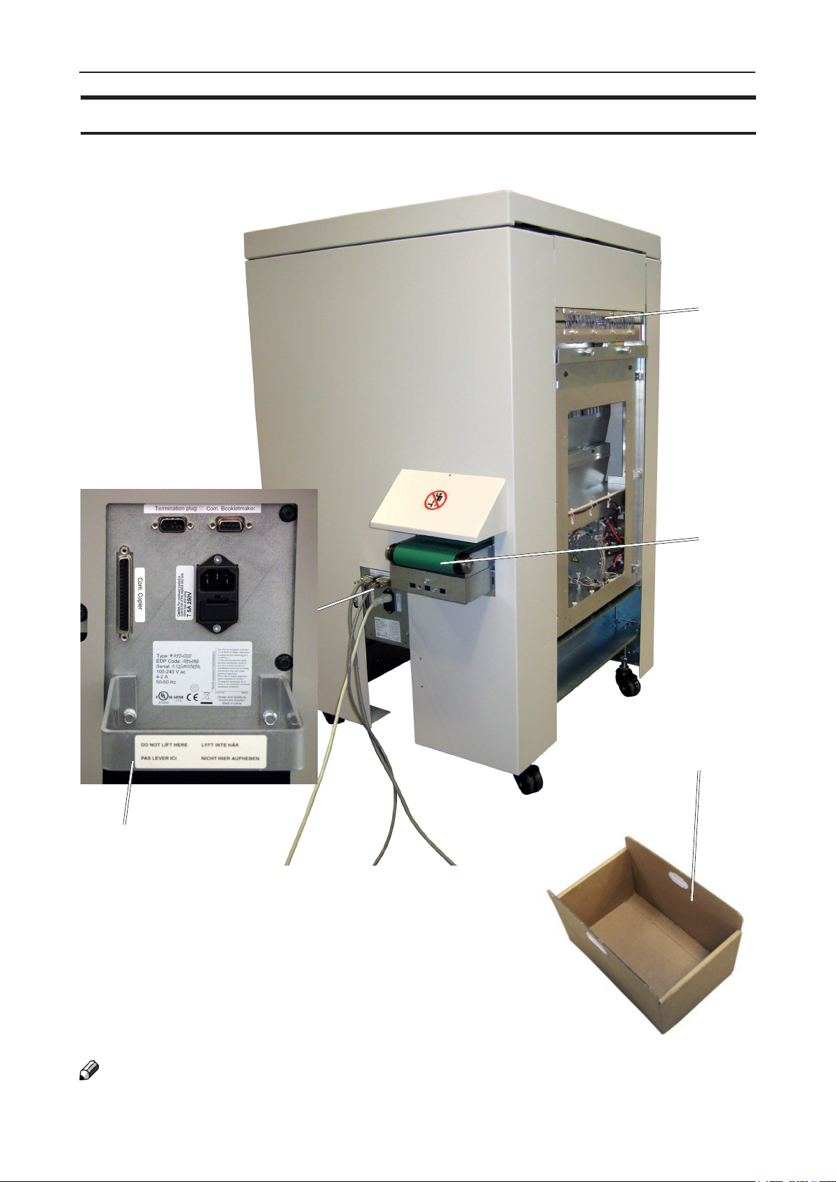
Rotate Crease Trim Module, continued
Connections bracket
1
4
1. Exit slot
2
3
2. Trim waste transport
3. Waste container
4. Cable protector
NOTE
How to connect cables, plugs and jumpers is described at the end of this manual.
20
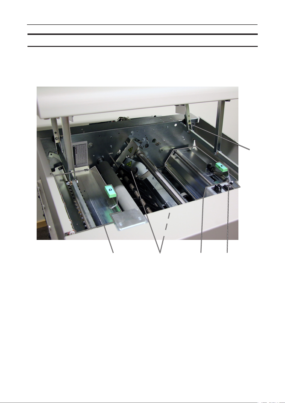
Rotate Crease Trim Module, continued
Parts that are important for setup, adjustments, troubleshooting or maintenance are highlighted below.
5
1. Exit section “D”
2. Bleed trimmer circular knives
3. Infeed Section “A”
4. Main switch
5. Counter
2
31 4
21
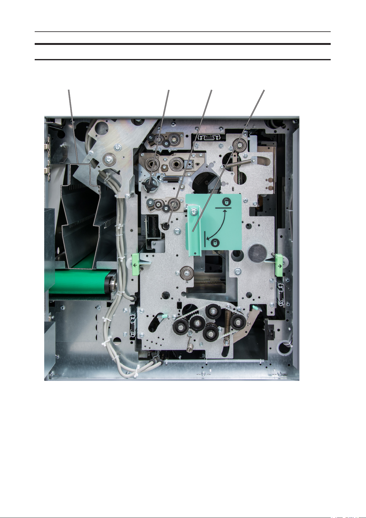
Rotate Crease Trim Module, continued
1
2 3 4
1 Waste chute(s)
2 Creaser registration adjustment
3 Bleed trimmer registration adjustment
4 Latch handle, slide
22
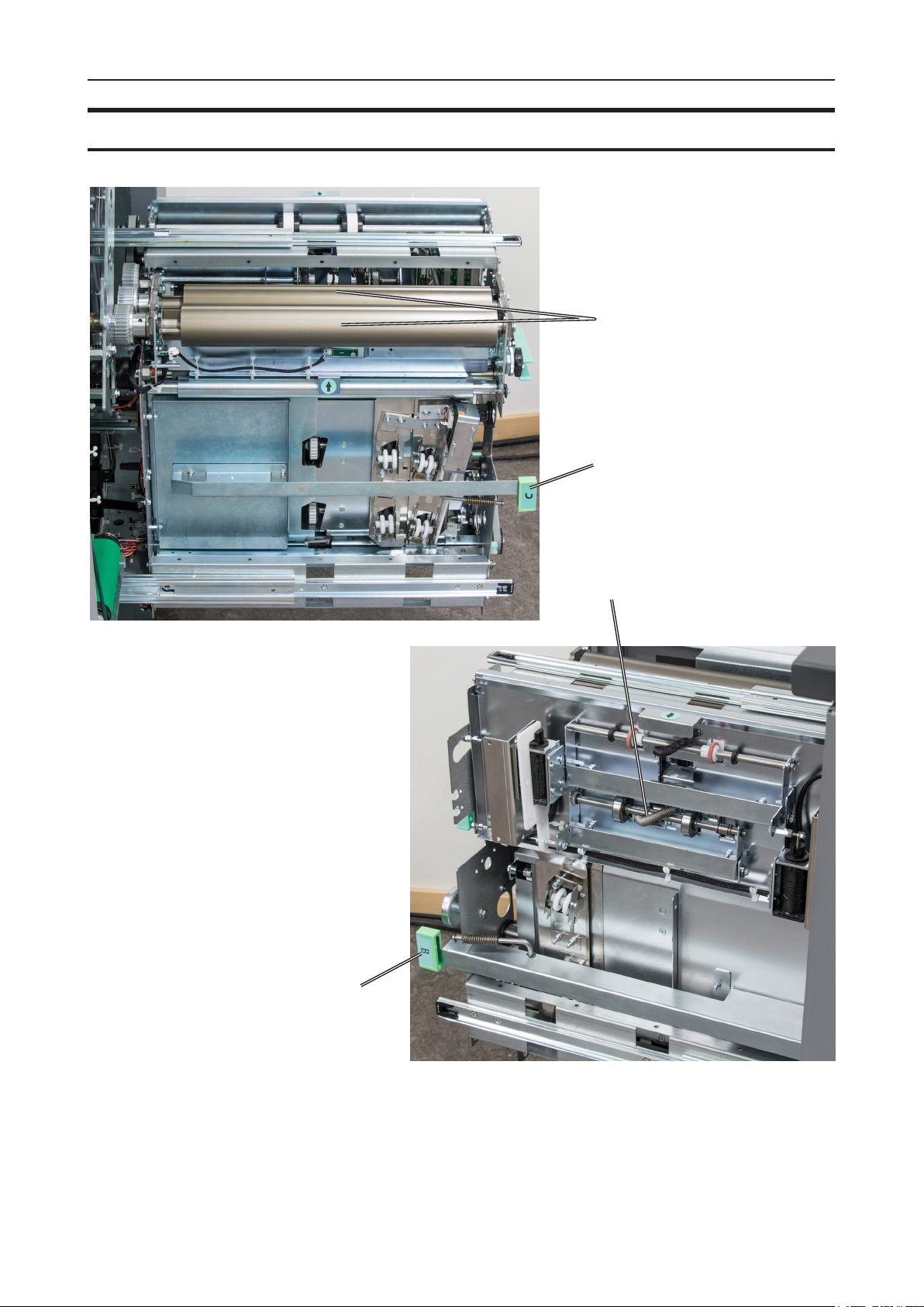
Rotate Crease Trim Module, continued
1
2
4
3
1 Creaser tools
2 Jam clearance bafe, ne registra-
tion, section “C”
3 Jam clearance bafe, coarse regis-
tration, section “B”
4 Rotator
23

Booklet Maker
Alive Logo
Alive Logo
With a BLM50 upgrade kit installed, the three
stripes below the user interface will signal status
as follows:
Not illuminated - System in power save mode or
switched off.
Steady blue - System is on and ready.
Alternating blue/yellow - Soft stop (staples low,
cover low, stacker full, waste bin full).
Alternating blue/red - Jam or malfunction
24
Cover Feeder
Parts that are important for setup, adjustments, troubleshooting or maintenance are highlighted below.
3
1
4
2
5
7
1 Loading capacity mark
2 Rear side guide
3 Feed roller assembly
4 Paper separator pad
6
5 Front side guide
6 Paper orientation indicator
7 Air nozzle (2x)
8 Jam clearance bafe
8
25

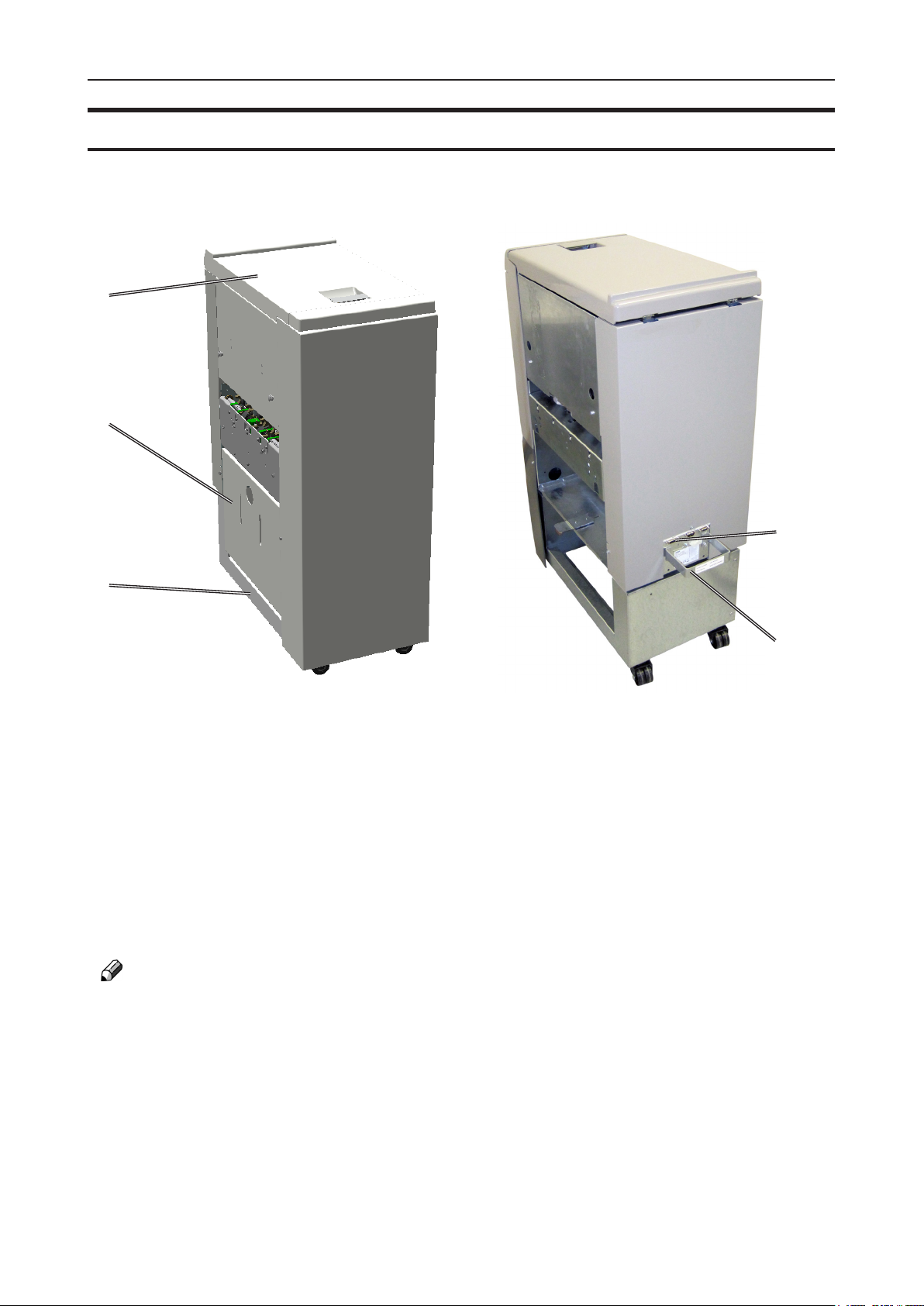
BookFold Module
1
3
2
1. Top cover
2. Base
3. Connections
4. Cable protector
NOTE:
How to connect cables, plugs and jumpers is described at the end of this manual.
4
26
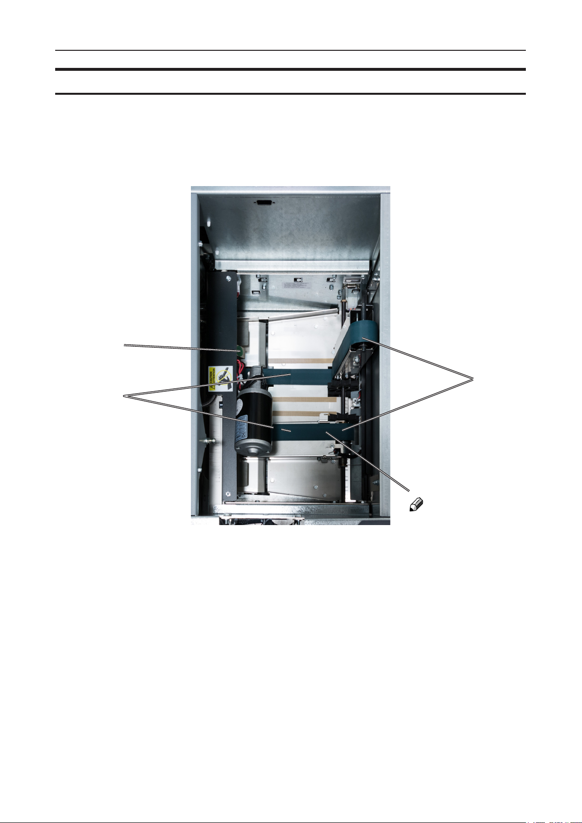
BookFold Module, continued
Parts that are important for setup, adjustments, troubleshooting or maintenance are highlighted below.
1
3
2
NOTE:
Upper feed belt on
operator side cannot
be lifted fully
BookFold Module, top view,
non operator side upper feed
belts lifted up
1 Upper feed belt release latch
2 Lower feed belts
3 Upper feed belts
27
Trimmer
1
2
4
3
1. Top cover
2. Trim bin
3. Base
4. Connections
5. Cable protector
NOTE:
How to connect cables, plugs and jumpers is described at the end of this manual.
5
28

Trimmer, continued
Parts that are important for setup, adjustments, troubleshooting or maintenance are highlighted below.
1
6
7
2
3
4
Trimmer, top view
1 Set counter
2 Exit drive lifting lever
3 Trimmer stop
4 Exit drive release
5 Exit compressing brackets
8
9
5
6 Infeed roller shaft
7 Trimmer fan
8 Transport belt
9 Upper trim knife
29
BST4000-1 Belt Stacker Module
The BST4000-1 High Capacity Belt Stacker Module is an option available for the
Plockmatic BLM50 or BLM35 Production Booklet Maker System. The stacker can be
congured in a straight line after the booklet maker system or at a 90 degree angle.
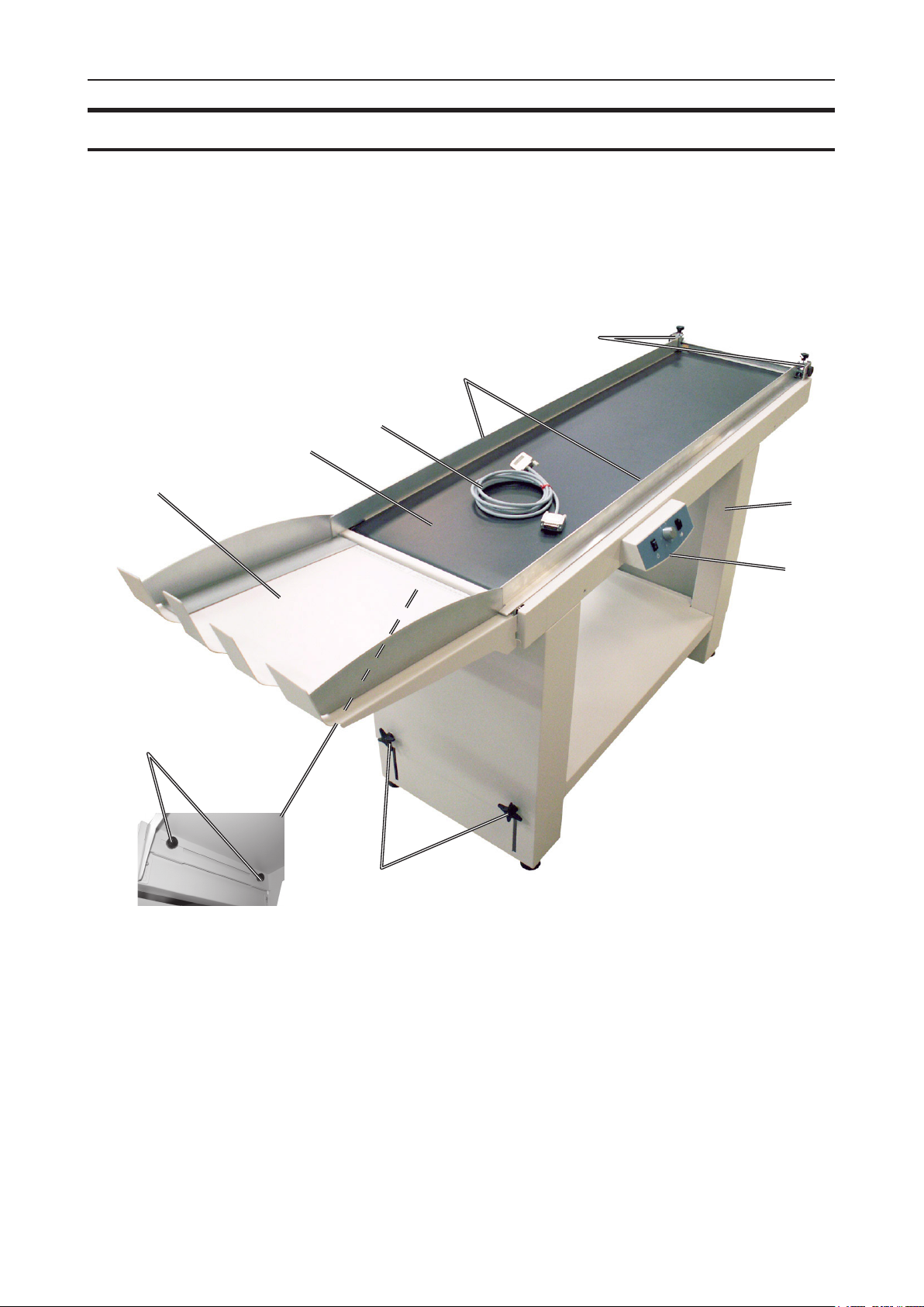
Parts that are important for setup, adjustments, troubleshooting or maintenance are highlighted below.
5
4
3
2
1
1
9
1 Control panel
2 Conveyor belt
2
6
7
30
8
1 Stacking tray
2 Conveyor belt
3 COM-cable
4 Side guides
5 Front end side guide adjustment knobs
6 Leg assembly
7 Control panel box
8 Height adjustment knobs (two on each leg)
9 Rear end side guide adjustment knobs (underneath)

BST4000-1 Control Panel
BST4000-1 Belt Stacker Module, continued
(1)
1 Power switch (on/off)
2 Belt speed selector
3 Run-out button (full speed)
BST4000-1 Principle of Operation
The belt is triggered by a signal from the Booklet Maker and will run for a set time.
The belt speed can be adjusted in order to optimize the stacking function for various
materials.
The Run-out button is used to gather the material after a job is nished.
The belt then moves at the highest speed, independent of the speed setting.
The power switch is also used to reset the unit after an overload situation.
(3)
(2)
31

Page intentionally blank.

1. Basics
Turning On / Off the Main Power
RCT, Booklet Maker, BookFold Module, Trimmer & BST Module
1
Make sure that the Booklet Maker, RCT
module (optional) and BST power cords are
plugged into the wall outlet.
NOTE:
BookFold (optional) and/or Trim (optional)
Modules are both powered from the Booklet
Maker.
2
Open the Booklet Maker top cover [A].
[A] [B]
[C] [D]
3
Set main power switch [B] on Booklet Maker
to ON position. If a BookFold Module and
Trimmer are attached, they will be powered
on via the Booklet Maker main power switch.
4
Close the Booklet Maker top cover.
5
Open the top cover of the RCT [C].
6
Set the main power switch [D] to ON position.
7
Close the RCT top cover.
[E]
8
Set main power switch [E] on the BST
Module to ON position.
33

Change staple cartridges and Check Stapler
The staple cartridges contains approximately 5000 staples each. Each cartridge includes
all wearable parts. The cartridges may need to be removed either for replacement or for
jam clearance.
1
Change left/right staple cartridge(s)
The Booklet Maker will indicate “Replace left/
right/left and right staple cartridges” when there
are approximately 20 staples left in the stapler
cartridge. Replace the indicated staple cartridge
by doing the following:
1
Open the Booklet Maker top cover.
2
Remove one or both staple cartridges by
lifting the lever [A], pressing either or both
levers [B] and pulling either or both staple
[B]
cartridges [C] out using the grip [E] at both
sides of the staple cartridge.
NOTE:
Lever [A] controls the stapler guides [D]. It is kept
in place by a magnet and can be hard to release.
Pressing either lever [B] makes it a bit easier to
overcome the force of the magnet.
[A]
[C]
[D]
3
Replace by pushing a new staple cartridge
into stapler until it snaps into position.
4
Put the stapler guides [D] back in position so
that lever is locked by the magnet.
5
Close booklet maker top cover and restart the
job.
[E]
34

Check left/right stapler
If the Booklet Maker indicates “Check right/left/
right and left stapler”, it means that there is a
jam in the indicated stapler. Remove the stapler
cartridge as described above.
1
Open the Booklet Maker top cover.
2
Remove either or both staple cartridge(s) as
described above.
3
Remove any sheets left in the Booklet Maker
and look for jammed staples stuck in the sheets.
4
Look inside the staple cartridge for jammed
staples and remove them if any.
5
Look at the clinchers [A] and remove any
jammed staples.
6
Push the staple cartridge(s) into stapler until
it snaps into position and lock stapler guides
in position as described above.
1
Cover Feeder
Loading covers
[A]
[A]
7
Close Booklet Maker top cover and restart job.
NOTE:
If the error message persists for no reason or if
staple jam reoccurs, replace the staple cartridge
as described above.
1
Make sure the cover sheets are well fanned
to avoid misfeeds or double-feeds.
2
Align the cover sheets well to achieve a
reliable feeding operation and good nishing
results.
3
Make sure that the ink has completely dried,
to avoid smearing.
4
Press on top of either air nozzle [A] to
lower the paper bin. Load the covers facing
downwards into the paper bin.
[B]
5
Adjust side guides [B] up against the cover
sheets until there is no clearance.
NOTE:
Make sure covers are same size as sheets fed
to booklet maker. When using an RCT, see Note
under “Changing settings, Finished Booklet Size,
Custom booklet size”.
35

Emptying the trim waste bin
Remove the trim waste bin by lifting it and pulling it out.
1
Trim bin
36

2
The Stacker can be used in either right-angled or in-line conguration with the Booklet
Maker. In-line mode is preferred if running heavy and large booklets.
Setting up Belt Stacker for Right-Angled Mode
Tighten the Side Guides at both
Move the inner Side Guide [A]
as far as possible towards the
Setting up Belt Stacker BST4000-1
Belt Stacker
Setting up Belt Stacker for right-angled mode
Follow these steps to correctly set up the Stacker
1
[B]
[A]
Move the inner Side Guide [A] as
far as possible towards the Booklet
Maker.
Booklet Maker.
2
Adjust the outer Side Guide [B] to
give at least 5mm (1/4”) play.
Adjust the outer Side Guide [B]
Tighten the Side Guides at both
to give at least 5 mm play.
ends.
3
Adjust the stacking with belt speed
ends.
selector.
Adjust the stacking with belt
speed selector. See page
11.
1
5 mm
37

Setting up Belt Stacker for Straight Mode
Adjust the stacking with belt speed
Adjust Side Guides to their
outermost position by loosening
Setting up Belt Stacker for straight mode
1
1 Adjust Side Guides to their
outermost position by loosening
knobs [A].
knobs [A].
2 Adjust the stacking with belt speed
selector [B].
selector.
[A]
[A]
[B]
38

2. Making Booklets
Guided Start
Guided Start is a function that takes you through all the basic settings the Booklet Maker
System needs to start booklet production in a few easy steps. Customizing settings and
ne adjustments are described later in this chapter.
Guided Start, step by step
Guided Start
Press the [Guided Start] button to
enter the Guided Start procedure.
Guided Start 1/8
This is the rst of up to 8 screens.
Depending on how the system is
congured and your selections
during this procedure, the number of
screens may be less than 8.
Conguration of the system also
affects the information shown and
button size will adapt to t screen.
To proceed from one screen to
another, press the [Next] button.
Guided Start 2/8
Select the sheet size loaded for the
job by pressing the corresponding
button.
For other sizes, follow “Custom sheet
size” described in section “Basic
Settings” below.
39

2
Guided Start 3/8
Choose either of two suggested
formats (except for B4 which only
has one suggested format).
When Face Trim is set to Auto,
a minimum trim, based on the
information from Set Thickness
Sensor, is calculated.
To set the trim manually, follow
“Finished Booklet size” described in
section “Basic Settings” below.
Guided Start 4/8
Select whether the Cover Feeder
is to be used or not and press the
corresponding button.
Guided Start 5/8
Load the covers face down.
NOTE:
Make sure covers are same size as
sheets fed to the Booklet Maker.
When using the bleed trim function
and feeding covers at the same time,
make sure covers loaded in Cover
Feeder are same size as sheets fed
from RCT to the Booklet Maker.
Guided Start 6/8
Select whether or not the booklet
should have a square formed spine
and press the corresponding button.
NOTE:
If the job includes a small number
of lighter weight sheets, the square
forming action will be switched off
and the BookFold Module will be
bypassed.
40

Guided Start 7/8
Select whether the booklets should
have a creased cover or not. This
feature is used to avoid high area
coverage toner cracking on the spine
on booklets containing less than 6
sheets.
Press the corresponding button.
After you are done, press the [Finish]
button to conclude the Guided Start.
Guided Start 8/8
All settings needed to begin
producing booklets are now set.
Start production by sending the print
job from the printer.
After the job has been sent to the
Booklet Maker System, the “Settings
for Booklet Production” screen is
shown.
2
From here you can customize and
ne-tune settings, save the job and
access the Tools screen.
Customizing and ne-tuning settings
is described below in this section.
How to save jobs is described in
section 4, “Jobs.”
Tools are described in section 3,
“Tools.”
Press Home to return to the “Start
Screen”.
41

Changing settings
General procedure
Settings can changed in one of two ways. “Temporary”, which means that the changes will remain
until a new job is loaded or “Permanent”, which means that the changes will be stored as a job.
This job can later be recalled.
Procedure for temporary changes:
From the Settings for Booklet Production screen, select the option you wish to alter and make your
2
selection. Conrm by pressing the green [check] button. You will be returned to the Settings for
Booklet Production screen
Procedure for permanent changes:
To keep your new settings, press the [Save current settings] button. Follow on screen instructions
to save your current settings as a new job or to an existing job.
NOTE:
Choose either of the above mentioned procedures when changing size, stapling, trimming, covers
or square forming as follows.
Depending on how the system is congured, the number of settings that can be selected varies.
The information on the screen and the size of the buttons will adapt to t the screen. Examples
below shows a fully congured system.
Basic settings
Input Sheet Size
Selecting standard paper sizes
From the Settings for Booklet Production screen, press the [Input Sheet Size]
button.
Select any standard paper size by
pressing the corresponding button and
save choice by pressing the green
[check] button.
Depending on conguration, available
standard paper sizes may differ. The
LEF paper sizes are only available if
there is a RCT installed.
For other paper sizes, follow “Custom
input sheet size” as described on the
next page.
42
NOTE:
Change of paper size will set Staple
position, Fold position, BookFold and
Crease to Auto and Cover to Off.
Any Fine-tuning (see section below) and
the “Booklets produced” counter will
also be reset.

AUTO sheet size
AUTO means that the Booklet Maker will adjust to the paper size information sent from the printer.
Auto Rotate will be turned on and a nished booklet size will be chosen from a predened list i.e.
the [Finished Booklet Size] button will be greyed out. No other settings will be affected.
Custom input sheet size
From the Input sheet size screen, press any
of the Custom size buttons and then press the
[Edit] button.
NOTE:
Changing to a Custom input sheet size will NOT
change Staple position, Fold position, Cover,
BookFold, Crease or Fine adjustment settings.
The “Booklets produced” counter will still be
reset.
Select Length and/or Width and key in the
desired value. Save the custom size format by
pressing the [check] button.
2
Finished Booklet Size
Auto trimming
Three different custom paper sizes can be stored.
NOTE:
A full number (incl. decimal point and fractions
of an inch/mm) must be entered before the
green [check] button appears.
Save setting by pressing the green [check] button.
From the Settings for Booklet Production
screen, press [Finished Booklet Size].
Trimming can now be set to either of two
suggested formats (except for B4 which only
has one suggested format) or Custom Booklet
Size.
When Face Trim is set to Auto, a minimum trim,
based on the information from Set Thickness
Sensor, is calculated.
For custom sized booklets, see below.
43

Custom booklet size
2
To set the trim manually, press [Custom Booklet
Size] and then [Edit].
To adjust the amount of face trim, press the
number on the [Length] button and type in the
desired length of the booklet, decimals included.
Also, the [plus] and [minus] buttons can be used
to change the numbers. The amount of face trim
is displayed in the box.
Press the green [check] button to conrm or
continue adjusting the amount of bleed trim.
To also adjust the amount of bleed trim, press
the number on the [Width] button and type in the
desired width of the booklet, decimals included.
Also the [plus] and [minus] buttons can be used
to change the numbers. The amount of bleed
trim is displayed in the box.
Press the green [check] button to conrm.
Back in the Finished Booklet size screen, the
size of the nished booklet and the amount of
face and bleed trim is displayed.
Press the green [check] button to conrm.
NOTE:
When using the bleed trim function and
feeding covers at the same time, make sure
covers loaded in Cover Feeder are the same
size as sheets fed from the RCT. According
to the example on the left, covers must be
300x450mm.
44

Customizing settings
Staple
Selecting stapling On or Off
From the Settings for Booklet Production
screen, press the [Staple] button.
2
Select On or Off by pressing the corresponding
button and save setting by pressing the green
[check] button.
Adjusting staple position
From the Settings for Booklet Production
screen, press the [Staple] button.
Set to Manual, the staple position can be altered
up to 3 mm (0.12”) on either side of the fold.
Press the [+] button move position closer to the
lead edge and press the [-] button move position
closer to the trail edge. Save setting by pressing
the green [check] button.
NOTE:
This change can be performed during run.
Set to Auto, the Booklet Maker uses the set
thickness sensor to adjust the staple position.
Press the [Auto] button and save setting by
pressing the green [check] button.
45
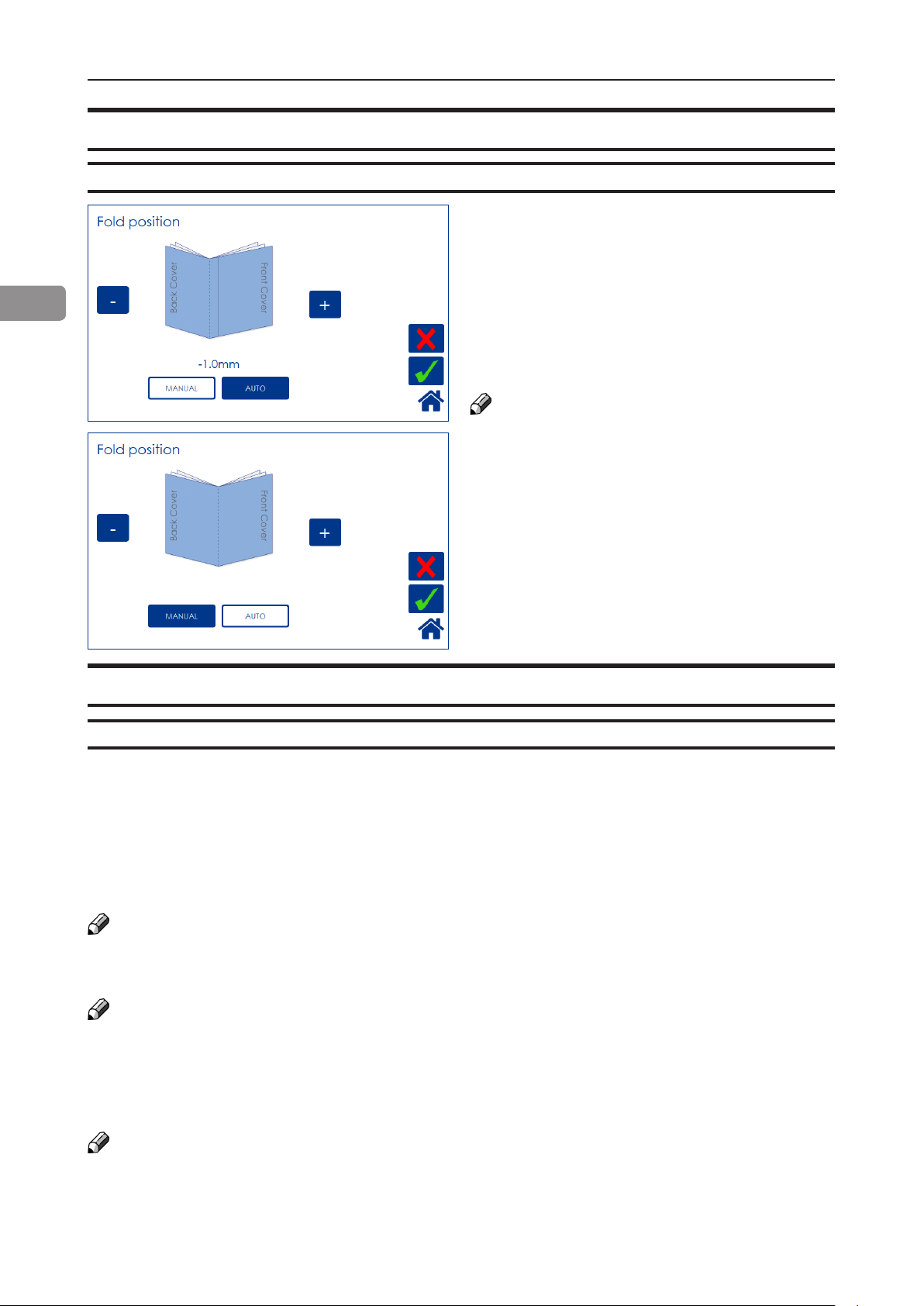
Fold position
Adjusting fold position
2
From the Settings for Booklet Production
screen, press the [Fold position] button.
The position of the fold can be changed up to 3
mm (0.12”) on either side of the center of the set.
Press the [+] button move position closer to the
lead edge and press the [-] button move position
closer to the trail edge. Save setting by pressing
the green [check] button.
NOTE:
This change can be performed during run.
You may want to turn off trimming to see the
result more clearly when you move the fold
position.
Set to Auto, the Booklet Maker uses the set
thickness sensor to adjust the fold position.
Press the [Auto] button and save setting by
pressing the green [check] button.
Cover
General
If the optional Cover Feeder is installed, the [Cover] button will be visible in the control panel. If
enabled, the cover feeder will automatically feed one sheet to each set from the printer, or one
sheet to each manually, hand-fed set.
A higher paper weight, pre-printed cover is fed to the set waiting in the compiler. The set and the
cover are then stapled and folded together.
Depending of system conguration, the booklet is then fed to the Belt Stacker, BookFold Module or
Trimmer.
NOTE:
Make sure sheets fed from Cover Feeder are the same size as sheets fed to booklet maker from
printer or by hand. When using an RCT, see Note under “Changing settings, Finished Booklet Size,
Custom booklet size”.
NOTE:
After selecting Cover [Yes], when the green [check] button is pressed, the Cover Feeder will try to
move the rst sheet into feeding postion. Therefore, load covers before pressing the green [check]
button to avoid the error message “Load covers” from being shown. See section 1, “Basics” for
how to load covers.
The Cover Feeder can also be used as a regular feeder. See section 3, “Tools”.
NOTE:
In case of a cover feeding jam/error, it is difcult to remove a stuck cover due to the very strong
separation nip. Removing the stack of sheets and then using the purge button on the stuck sheet
is the easiest way to remove a cover that is stuck.
46

Cover
Air Separation
From the Settings for Booklet Production
screen, press the [Cover] button. Press the
[Yes] button and conrm by pressing the green
[check] button.
2
You may want to increase the Air ow when
running thick, heavy covers. From the Cover
screen, press the [Air separation] button.
Set the desired amount of air ow by pressing
the corresponding button and save setting by
pressing the green [check] button. Default setting is 40%.
Double Sheet Detection
From the Cover screen, press the [Double
sheet detection] button.
Set the detection to On or Off by pressing
the corresponding button and save setting by
pressing the green [check] button.
Normally, double sheet detection should be set
to “On” when you are feeding covers. However,
if you experience “false double sheet feeds”,
for example when running covers that are thick,
with dark print or with mixed prints on the
covers, the double sheet detection can be set
to Off.
NOTE:
Misfeed detection will work regardless of how
Double Sheet detection is set.
47

Purge Cover
The Purge mode is used when you want to
completely empty the Cover Feeder from covers.
1 Remove all cover sheets from the bin.
2 Press the [Purge Cover] button and conrm
by pressing the green [check] button. The
2
NOTE:
If you open and close the top cover without removing the cover sheet, the cover sheet will be
stapled and folded and then fed to the stacker.
pre-fed cover sheet will now be fed into the
Booklet Maker to the stapling area, but will
not be stapled.
3 Open top cover and remove the cover sheet.
BookFold
General
The BookFold Module has three different settings - Manual, Auto and Off.
In Manual mode, there are eight different modes of BookFold pressure to choose from.
Set to Auto, information from the set thickness sensor in the Booklet Maker is used to calculate the
most appropriate mode between 1 and 7. See guidance table below.
Select Off to bypass the BookFold Module without any square forming action.
NOTE:
When the BookFold Module is set to Auto and the booklet has less than approximately 6 sheets/
booklet, the BookFold Module will bypass the square forming action.
For some jobs, Auto mode may not provide the optimum result. In this case, ne tune by selecting
a mode in Manual mode - see the table below.
Mode 8 is a heavy duty setting in case of extra demanding media. Mode 8 is not included in the
Auto setting and therefore must be selected manually.
Use the manual modes to override the auto function. There are eight different manual modes to
select from.
Table below is approximate numbers and is based on 80 gsm / 20 lb Bond sheets.
Mode Number of sheets in the set Notes
1 Approximately 6 to 10
2 Approximately 11 to 16
3 Approximately 17 to 22
4 Approximately 23 to 29
5 Approximately 30 to 35
6 Approximately 36 to 43
7 Approximately 44 to 50
8 Heavy duty setting in case of
extra demanding media.
BookFold pressure settings guidance table
continued on next page
48

The table below shows highest supported BookFold pressure settings on BLM35 and BLM50 Production Booklet Maker systems.
NOTE:
The following table indicates maximum BookFold pressure setting that can be used on the
Production Booklet Maker systems without slowing the printer down.
Number of sheets A4 A3 SRA3 8.5x11" 11x17" 12x18"
1-5 2 4 7 1 4 7
6-10 4 7 8 4 7 8
11-15 7 8 8 7 8 8
16-20 7 8 8 7 8 8
21-30 8 8 8 8 8 8
31-50 8 8 8 8 8 8
NOTE:
When square forming thick booklets with a thin cover, the cover sheet may be spaced away from
the body of the book and/or it may be crushed in the square forming process.
This phenomenon is eliminated/reduced by using a heavier media as the cover. If using a heavier
cover is not an option, using a lower BookFold pressure setting in the square forming process may
improve booklet appearance.
Selecting BookFold pressure setting
2
From the Settings for Booklet Production
screen, press the [BookFold] button.
Press the [Manual] button and select the desired amount of pressure using the [+] and [-]
buttons. Save setting by pressing the green
[check] button.
49
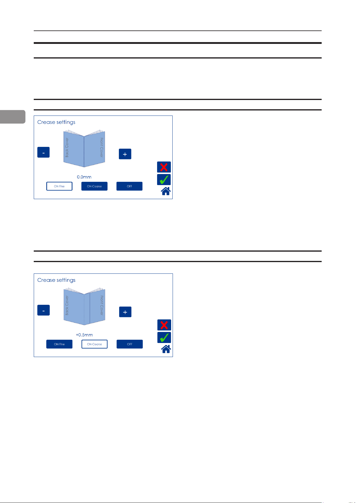
Crease
The Crease function makes it possible to crease the cover sheet of the booklet in order to avoid
toner cracking or aking at the fold.
Crease Mode
2
Crease position
From the Settings for Booklet Production
screen, press the [Crease] button.
Press the corresponding button to choose [On
Fine], [On Coarse] or [OFF].
Fine is recommended for cover sheets less than
120 gsm / 32 lb Bond.
For sheets heavier than that, select Coarse.
When you want to turn the Creaser off, select
Off.
Press the green [check] button to conrm.
The crease is initially set to the center of the
sheet. Operators have the option to offset the
position of the crease using the [+] or [-] buttons.
Press the [+] button move position closer to the
lead edge and press the [-] button move position closer to the trail edge. Regardless if you
chose Fine or Coarse creasing, each press of a
button will move the crease 0.1 mm / 0.004”.
50
When done, press the green [check] button to
conrm.
The illustration shows that the crease is offset
0.5 mm towards the trail edge.

Fine-tuning booklet appearance
Set registration (ne adjustment)
You can ne-tune the booklet quality by adjust-
ing the joggers in the booklet maker.
From the Settings for Booklet Production
screen, press the [Finished Booklet Size] button.
From the Finished Booklet size screen, press
the [Set registration (ne adjustment)] button.
2
Press the [-] and [+] buttons to alter either or
both registration values.
Negative value means a tighter registration.
NOTE:
Too tight of a setting may worsen the result.
After setting registration value, press the [Check
set registration] button and follow the instructions on screen.
If you are satised with the registration, conrm
by pressing the green [check] button.
If not, press the [-] and [+] buttons to enter new
value. Check out the new value by pressing the
[Verify adjustments] button.
Press the green [check] button when you are
satised.
51

Bleed Trimmer - Asymmetric Side Trim
From the Finished Booklet size screen, press
the [Asymetric Side Trim] button.
2
Choose Asymmetric Side Trim if you want to
offset the bleed trim. Move using the [+] and [-]
buttons and press the green [check] button to
save setting.
Settings as in the example above would result
in a booklet with trim settings shown in the im-
age to the left.
Bleed Trimmer - Cover Adjust
52
From the Finished Booklet size screen, press
the [Cover Adjust] button.
Choose Cover Adjust to compensate for different
shrinkage of body- and booklet cover stock. This
can occur under some conditions and can be
caused by different paper stocks shrinking due to
the heat and pressure of the fusing process.
Adjusting these settings can improve booklet
appearance, especially if the cover is dark and
the body sheets are bright.
The shown example will make the cover sheet
0.7mm bigger than the body stock.

Hand-feeding
The Booklet maker can be operated in two modes. On-line mode, when used together with
the printer, or off-line mode, working as a stand-alone unit.
Hand feed mode
[A] [C][B]
1
Setup the Booklet Maker to the correct
paper size.
2
Open the Hand Feed Cover [B].
3
Adjust the hand feeding paper guides
[A] to the correct paper size.
4
Start hand feeding sets [C] when the
text [Ready to feed!] is shown in the
user interface.
2
5
To stop hand feeding, close the Hand
Feed Cover.
NOTE:
RCT features will not be available.
53

Page intentionally blank.

3. Tools
The Tools screen
From the Start screen or the Settings
for Booklet Production screen, press the
[Tools] button to get to the General System
Settings screen. Select the setting you want to
change by pressing the corresponding button.
Press the green [check] button to save your
changes.
Stacker full detection
Units
Set Stacker Full Detection to ON if you want
the system to stop and cycle down when the
stacker is full.
Select millimeters or inches by pressing the cor-
responding button.
55

Software version
3
Paper path light
Select module by pressing the corresponding
button to display the software version. Press
[Exit] button to go back to the Settings screen.
This function is for service purposes.
To turn the paper path light on, press [ON 5 min]
button and save by pressing the [OK] button.
Language
Select desired language by pressing the corresponding button.
56
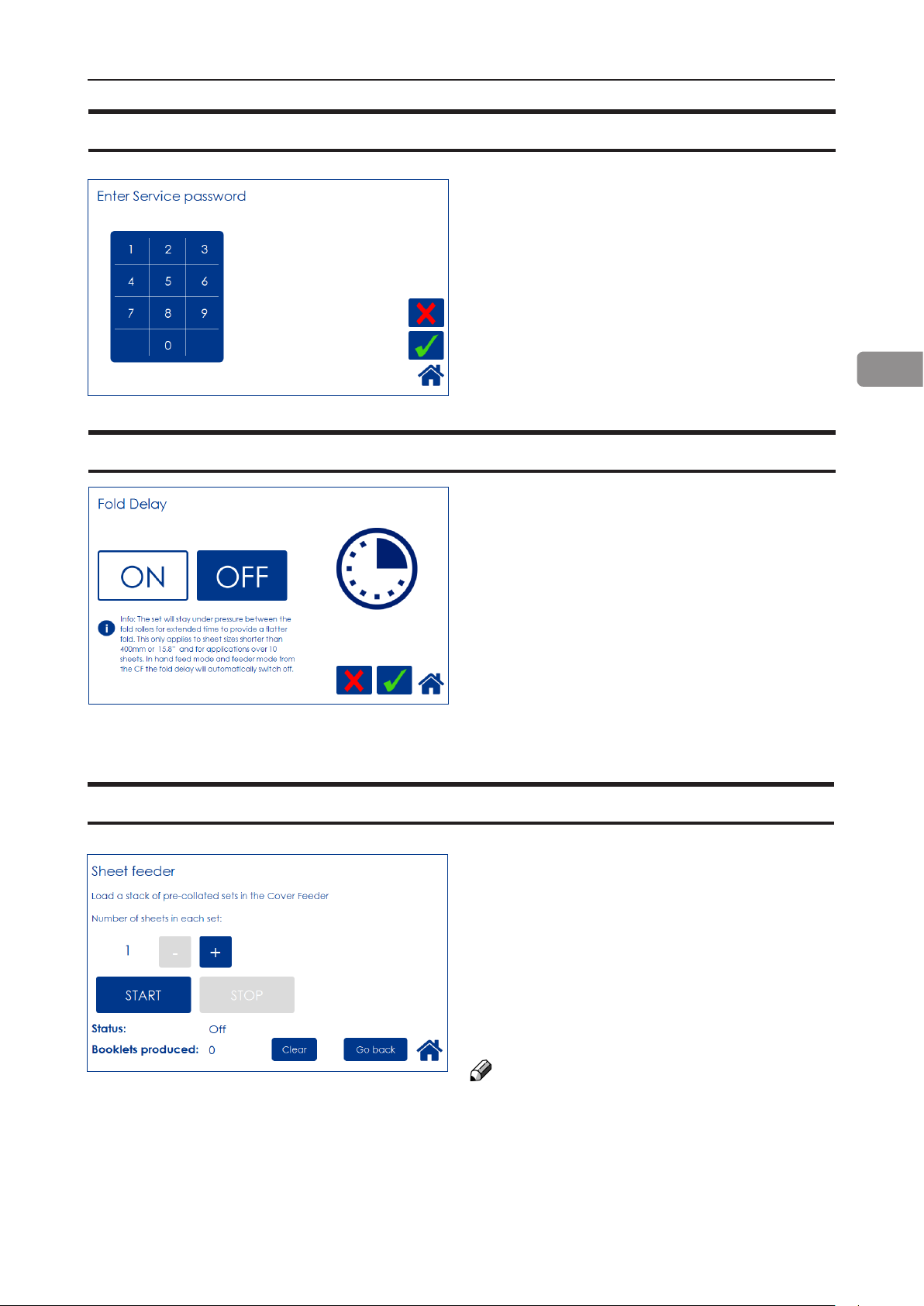
Service mode
Fold delay
This function is for authorized service personnel
only and is password protected.
3
With this feature, the set will stay under pressure between the fold rollers for an extended
time to provide a atter fold. This only applies
to sheet sizes shorter than 400mm or 15.8”
and for applications over 10 sheets. In hand
feed mode and feeder mode from the CF, the
fold delay will automatically switch off.
Sheet feeder
This function allows you to use the Cover Feed-
er as a regular Feeder. Load the Cover Feeder,
enter the desired number of sheets in each set
and press the [Start] button to begin folding.
Press the [Stop] button to stop.
See section 1, “Basics”, for how to load the
cover feeder.
See section 2, “Making Booklets” for how to ad-
just Air Separation and Double sheet detection.
NOTE:
To avoid the error message “Load covers”, load
covers before pressing the [START] button.
57

Auto Rotate
If your system includes the optional RCT mod-
ule, you can select whether you want Auto
Rotate function to be ON or OFF by pressing
the corresponding button.
It is recommended to keep this ON.
When turned on, the Rotator will automatically
rotate all sheet sizes sent from the printer in
long edge feed, enabling higher printer productivity.
3
Selecting OFF will prevent sheets from being
rotated when possible. Sheet length has to
exceed 275mm / 10.6”. Otherwise Auto Rotate
will automatically be changed to ON and sheets
will be rotated.
BookFold offset
The BookFold pressure setting is set to a standard that should suit most applications.
Operators have the option of sharpening or softening the square edges based on application or
preference. Customizing this setting will affect modes 1 to 7 but not mode 8.
Select sharper edges by pressing the [+] button
or softer edges by pressing the [-] button.
NOTE:
BookFold Offset affects modes 1 -7 only.
58

4. Jobs
Handling jobs
The Booklet Maker has a maximum storage capacity of 20 different jobs. To make
temporary changes in the actual job settings or temporary changes of a stored job, see
section 2, “Making Booklets.”
From the Start screen, press the [Jobs] button to be able to store, change or delete jobs.
Saving a Job
To store a job, press from the Settings for
Booklet Production screen.
Press the [Save as a NEW job] button and then
press the green [check] button to continue.
The [Save to existing job] button is only available if a job is currently loaded.
Enter a job name and save by pressing the
green [check] button.
To delete last character, press the [←] button
59
Opening and handling stored Jobs
To access already stored jobs,
press from the Start Screen.
4
Open (load) any stored job by pressing the job
and conrm by pressing the green [check] mark.
Delete any stored job by pressing the job but-
ton, the waste bin symbol and then conrm by
pressing the [Yes] button.
NOTE:
The currently loaded job cannot be deleted.
The button [Save to existing job] is only available if a saved job is currently loaded. Press
the [Save to existing job] button to overwrite the
currently loaded job.
Press the green [check] button to conrm.
60
The name of the currently loaded job is shown
in the upper right corner. An asterisk next to the
name shows that changes to the job have been
made and that the changes have not yet been
saved.
5. Clearing Misfeed(s)
Clearing misfeed(s)
General
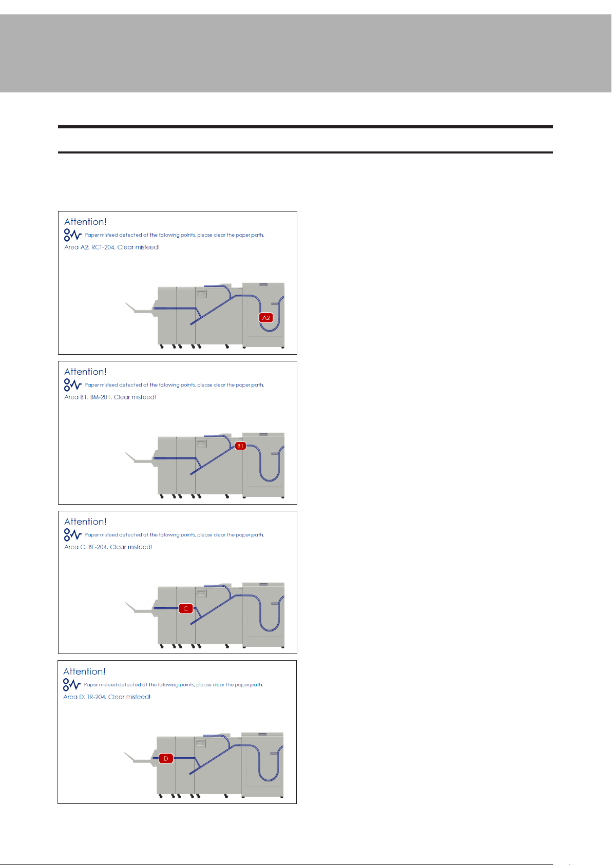
If a misfeed condition should occur, it is indicated on the Booklet Maker display. The
message “Clear Misfeed(s)”, an error code and the location of the misfeed is displayed.
See examples below.
Misfeeds in the Rotate Crease Trim Module
are indicated by the error code RCT-XXX.
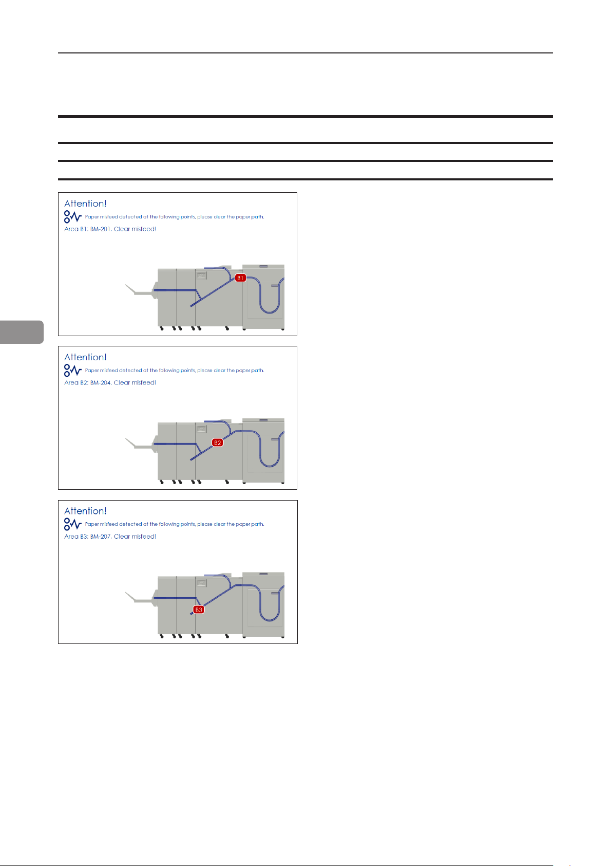
Misfeeds in the Booklet Maker are indicated
by the error code BM-XXX and visually
where in the Booklet Maker (B1, B2 or B3)
the misfeed occurred.
Misfeeds in the BookFold Module are
indicated by the error code BF-XXX.
Misfeeds in the Trimmer are indicated by
the error code TR-XXX.
61

RCT Module
Clearing misfeed(s)
Infeed “A” area and exit “D” area
1
Open the RCT top cover.
2
Lift up bafes “A” and “D” if needed.
3
Remove any misfeed(s).
4
Lower bafes “A” and “D” to normal position
5
Misfeed(s) in the trimmer area are rolled out by rotating the rubber surfaced pinch
roller [A].
5
6
Close the top cover.
WARNING
Do not put your ngers within knife protections (B).
Doing so may result in injury.
62
Bafe D
[A]
[B]
Bafe A

Registration and creaser area
1
Open the slide door [A].
2
Unlatch and pull out the slide [B].
3
Open bafes “B” and “C” if needed.
4
Remove any misfeed(s).
5
Close bafes “B” and “C”.
6
Push in and latch the slide.
7
Always remove any residual waste from waste channel and waste [C] belt before
closing the slide door.
8
Close the slide door.
Clearing jams in the waste transport
The waste transport is easily accessible through the slide door. Shreds jammed in or wrapped
around the knife assembly are also accessible through the slide door.
CAUTION
Under no circumstances should jams around the trimmer blades be cleared using metallic
tools. The edges are very fragile and easily damaged.
5
[A] [C] [B]Bafe C Bafe B
63
Booklet Maker
Clearing misfeed(s)
Inside the Booklet Maker
5
To clear a misfeed indicated in Area B1
1 Open the top cover.
2 Remove misfed sheets.
3 Close the top cover.
To clear a misfeed indicated in Area B2
1 Open the top cover.
2 Close top cover.
If system does not purge, open top cover and
remove misfed sheets manually.
To clear a misfeed indicated in Area B3
1 Open the top cover.
2 Close top cover.
If misfeed condition remains:
1 Switch off the main power.
2 Switch on the main power.
64

Clearing misfeed(s), continued
Clearing misfeed in infeed area
1
Open the top cover.
2
Lift the paper guide [A] as shown in picture.
3
Remove misfed sheets.
4
Close top cover.
5
[A]
65

Clearing misfeed(s), continued
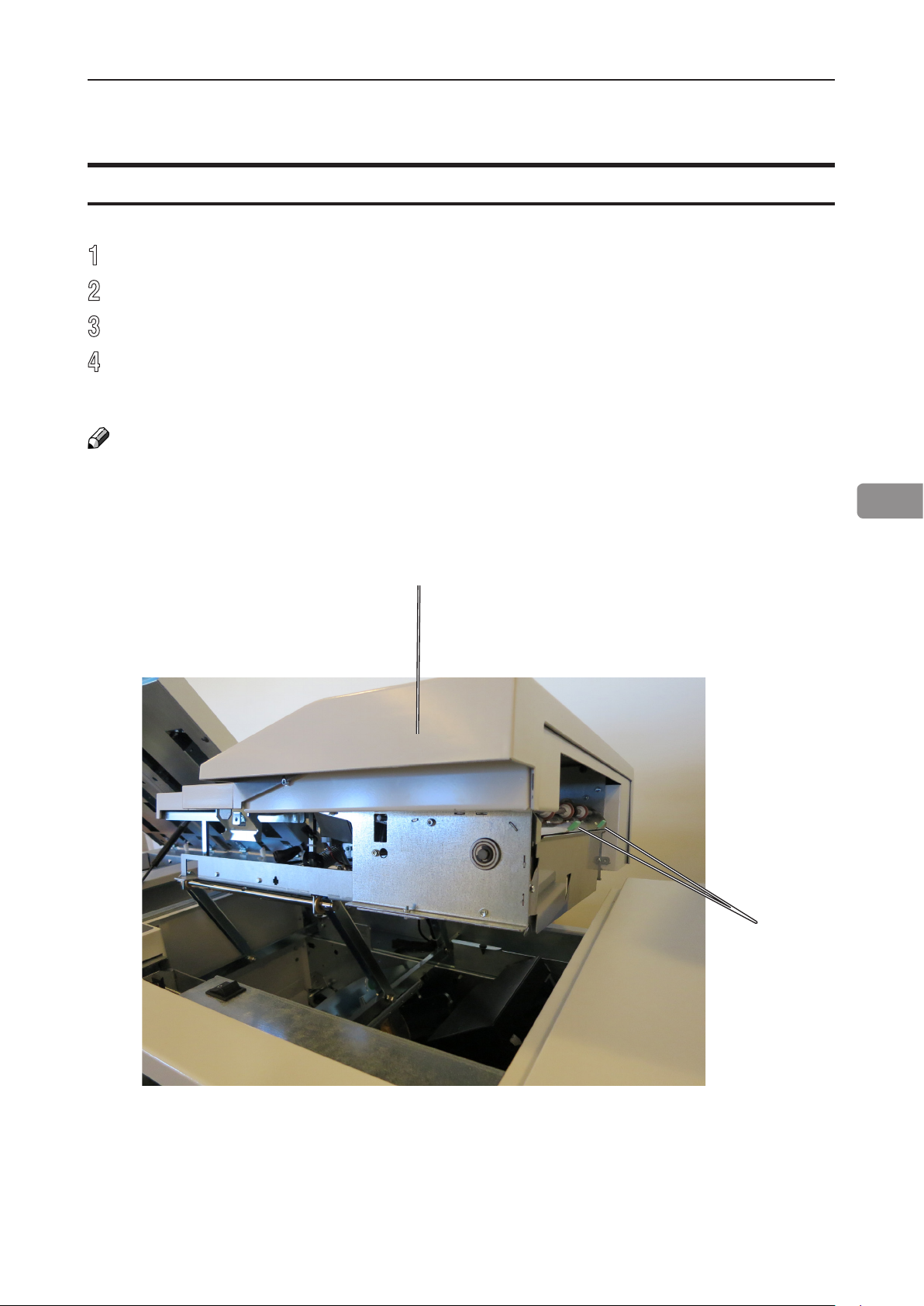
Clearing misfeed in folder area
1
Open the top cover.
2
Open the fold roller paper guide [A] by pushing (arrow 1), lifting (arrow 2) and pivoting
(arrow 3) to access any misfed or jammed sheets/booklets between the lower and
upper pair of fold rollers.
3
Remove sheets/booklets in folder area between fold rollers.
4
In reversed manner, place the fold roller paper guide back in operating position.
NOTE:
Make sure the fold roller paper guide is locked in operating position [B] at both sides.
5
5
Close top cover.
[A]
66
2
1
3
Fold roller
paper guide
locks here
[B]
Cover Feeder
Clearing misfeed(s) in vertical transport area
1
Open the top cover [A].
2
Lift the jam clearance bafe [B].
3
Remove the misfed sheet.
4
Put the jam clearance bafe back in normal position.
NOTE:
In case of a cover feeding jam/error, it is difcult to remove a stuck cover due to the very strong
separation nip. Removing the stack of sheets and then lifting the jam clearance bafe is the
easiest way to remove a cover that is stuck.
[A]
5
[B]
67

BookFold Module
Clearing misfeed(s)
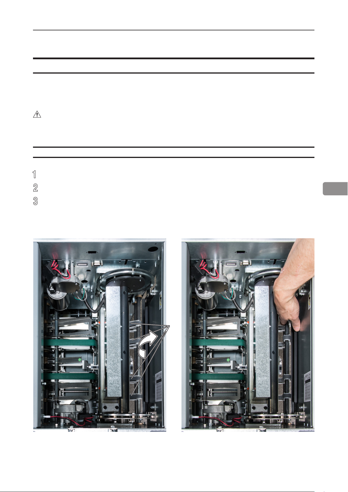
Inside the BookFold Module
1
Open the top cover.
2
Lift up upper feed belts (A) to access jammed/misfed booklets.
NOTE:
Press the green dots (B) (only one visible in picture) on the latches to release.
3
Remove the jammed/misfed booklets.
4
Place the upper feed belts in normal position.
5
5
Close the top cover.
B
A
B
NOTE:
The upper feed belt on the
operator side cannot be lifted fully.
68
Trimmer
Clearing misfeed(s)
The upper trimmer blade on the trimmer is protected by a knife protection plate that moves
away during the cutting stroke.
WARNING
Never put ngers or other body parts between the upper and lower trimmer knives.
Clearing misfeed in input area
1
Raise the rightmost side of the infeed roller shaft assembly (A).
2
Remove the misfed sheets in the infeed area.
3
After the misfed sheets are removed, place the infeed roller shaft assembly into
operating position.
5
[A]
infeed roller shaft assy. in normal position infeed roller shaft assy. lifted
69
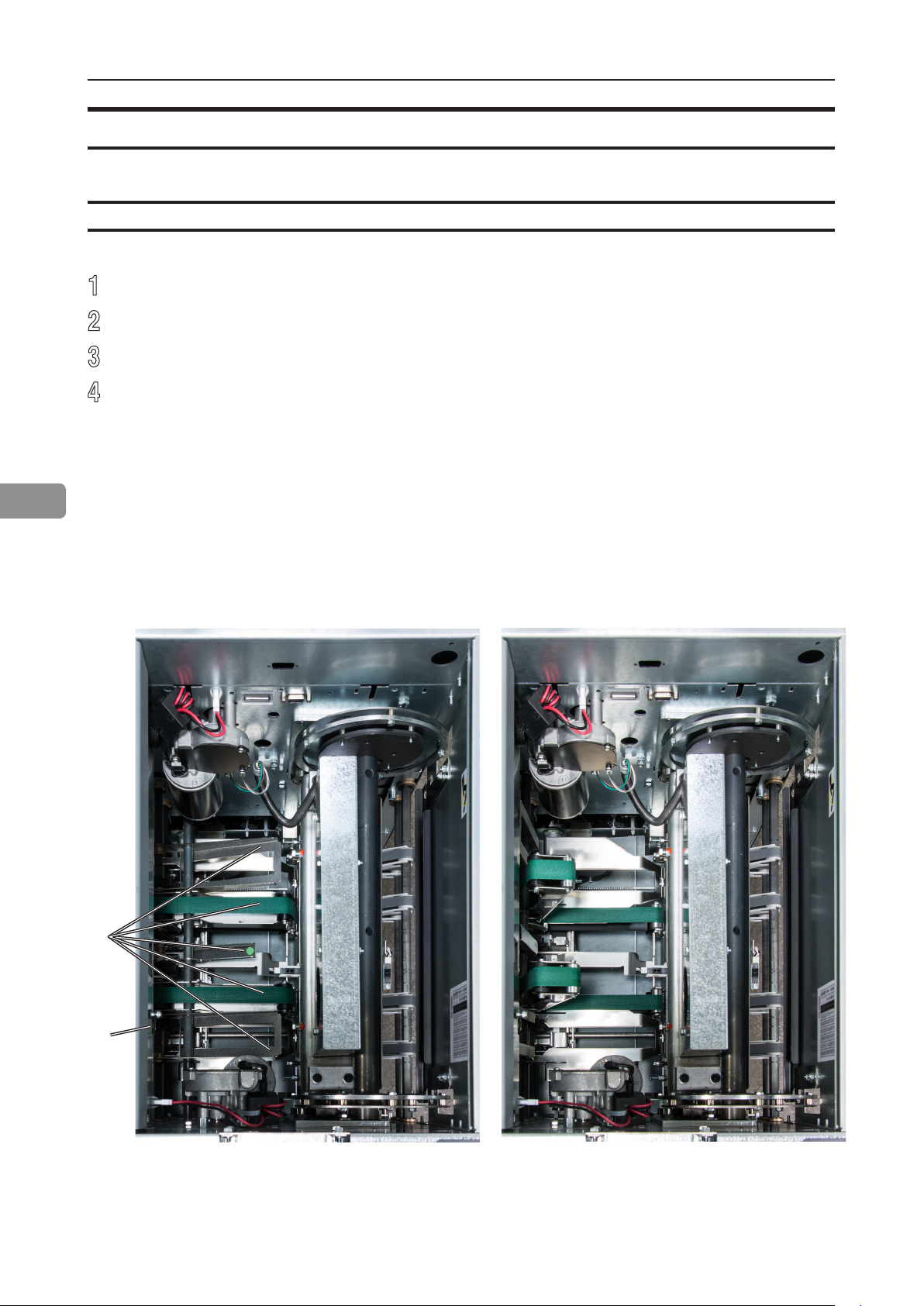
Clearing misfeed(s), continued
Clearing misfeed in exit area
1
Lift the exit compressing brackets and transport belts [B] at the green dot.
2
Secure using the latch [C]. Not clearly visible in picture
3
Remove the misfed sheets from the exit area.
4
After the misfed sheets are removed, release the latch [C] and place the exit
compressing brackets in operating position.
5
[B]
[C]
70
Exit compressing brackets in normal position Exit compressing brackets lifted

Belt Stacker
Clearing misfeed(s)
Clearing misfeed on belt stacker
1
Lift the belt stacker exit cover (A).
2
Remove jammed/misfed booklets.
3
Place belt stacker exit cover back in operating position.
A
5
71

Page intentionally blank.

6. Troubleshooting
Fault codes
General
When there is a misfeed or fault condition in the Booklet Maker system, a code and/or a
message will be displayed on the UI. Table and fault code descriptions below will guide
you troubleshooting.
If frequent input jams are experienced please check paper curl and de-curler adjustments
in printer operator guide.
For fault codes other than specied below - remove any paper in the paper path and
power Off and On the system.
NOTE:
If procedures in this manual do not rectify the problem an authorized technician will be
needed.
RCT fault codes
RCT Module
Code / message Explanation / action
RCT-001 - RCT-171 Possible fault in
area, please power off and power on to
recover!
RCT201 - RCT212 and RCT230
Clear misfeed!
Empty trim bin from RCT module and
check waste belt!
Indicates that there might be an internal communication
error between the RCT module and the Booklet Maker.
Check that the RCT is powered up and that the
communication cable between the RCT module and the
Booklet Maker is OK. Power off and on the system. If
problem persists, contact customer support.
A misfeed has occurred in the RCT module.
See section 5, “Clearing Misfeed(s)” for how to clear
misfeed(s).
If feed errors occurs in the paper path or in the waste
transport system, check for obstructions. If no obvious
obstructions are found, see section 7, “REMARKS”
Maintaining Your Machine.
Check / Empty Waste container and check Waste
Transport for buildup of trim waste strips.
It is highly recommended to empty the waste box
whenever the system stops to keep up productivity.
73

Booklet Maker fault codes
Booklet Maker
Code / message Explanation / action
BM-001 - BM-169 Possible fault in
area, please power off and power on to
recover!
BM-170, Incompatible RCT software! Software in the RCT is reported to be of an incompatible
BM-201 - BM-208 Clear misfeed! A misfeed has occurred in the Booklet maker.
BM-401, Check right stapler!
BM-402, Check left stapler!
BM-403, Check right and left stapler!
BM-404, Set too thick, remove set from
booklet maker!
BM-407 Too many sheets, remove set
6
and reduce number of sheets in the
job!
BM-408 CF empty, remove incomplete
set from Booklet Maker!
BM-600 - BM-617 File error! Indicates that there might be an internal communication
Replace right staple cartridge!
Replace left staple cartridge!
Replace right and left staple
cartridges!
Remove purged cover from inside
booklet maker!
Size mismatch! Hold the job in the
printer and check paper size settings.
Indicates that there might be an internal communication
error. Power off and on the system. If problem persists,
contact customer support.
version. Power off and on the system. If problem
persists, contact customer support.
See section 5, “Clearing Misfeed(s)” for how to clear
misfeed(s).
Indicates jam in either or both staplers.
Check staple cartridge(s) according to procedure in
section 1, “Basics.”
Indicates that the set from the copier is outside Booklet
Maker specications and is too thick to be folded. Open
top cover and remove set. Close top cover.
Indicating there are too many sheets in the Booklet
Maker. Open top cover and remove set. Close top cover.
Reduce the number of sheets in the job.
Using the Cover Feeder as a regular feeder, the bin has
run out of sheets before a set was completed. Open top
cover and remove the incomplete set from the Booklet
Maker.
error. Power off and on the system. If problem persists,
contact customer support.
Indicates almost out of staples in either or both staplers.
Change staple cartridge(s) according to procedure in
section 1, “Basics.”
There is a purged cover inside the Booket Maker. Open
top cover and remove set. Close top cover.
There is a mismatch between paper size in the printer
and the Booklet Maker. Input sheet size in the Booklet
Maker is automatically set to AUTO. Press the [Done]
button to continue with the Booklet Maker in AUTO
mode or hold the printer and a check paper size
settings.
74

Cover Feeder fault codes
Cover Feeder
Code / message Explanation / action
CF-001 - CF-012 Possible fault in
area, please power off and power on to
recover!
CF-201 Out of covers, remove sheets
from Booklet Maker!
CF-202 - CF205 and CF-207 Clear
misfeed!
Double feed from CF, remove double
from inside the booklet maker.
Indicates that there might be an internal communication
error. Power off and on the system. If problem persists,
contact customer support.
Indicates “Out of covers” in the Cover Feeder. Load
covers according to section 1, “Basics.”
A misfeed has occurred in the Cover Feeder.
Check cover loading according to section 1, “Basics”,
Cover Feeder.
If problem persists, clean separator pad according to
section 7, “REMARKS.”
A double feed has occurred in the Cover Feeder.
If there was a true double:
1. Check for proper loading of covers according to
section 1, “Basics”, Cover Feeder.
2. Increase air ow according to section 2, “Making
Booklets.”
3. Clean feed belts according to section 7,
“REMARKS”, Maintaining your machines.
6
Cover size not equal to paper size.
Change cover size!
If there is a false double:
1. Check that covers are within specication.
2. Temporary turn double sheet detection off. See
section 2, “Making Booklets”, Customizing settings.
If the covers fed are thick, with dark print or with mixed
prints on the covers, double feeding may be displayed
even if that is not the case.
Indicates that there is a format mismatch between the
sheets loaded in the Cover Feeder and the sheets in the
Booklet Maker.
There are two options:
1. Correct either mismatch and press the [Done] button.
2. Turn the Cover Feeder off by pressing the [Turn cover
off] button to continue booklet making but without
feeding covers.
75

Cover Feeder fault codes, continued
Cover Feeder, continued
Code / message Explanation / action
Cover stack is low, please add covers! Indicates that the Cover Feeder is almost out of Covers.
There are two ways to continue operation.
1. Loading more cover sheets:
2. Using up the remaining cover sheets that are
Be aware that if you use alternative 2, the system will
hard stop i.e. without completing the cycle when there is
no covers left.
Load covers! Message is displayed when covers are empty. Message
6
will also be displayed if the green [check] button was
pressed after deciding to use Covers but before the bin
was loaded.
There are two ways to continue operation.
1. If you wish to continue production:
2. If cover job is nished and you wish to run a new job
Load more cover sheets according to section 2,
“Making Booklets” and press the [Done] button. The
message will extinguish and copier will start.
loaded:
Press the [Dismiss] button. The message will
extinguish and copier will start.
NOTE:
Load cover sheets according to section 2, “Making
Booklets” and press the [Done] button. The message
will extinguish and copier will start.
without covers:
Select Cover Off in the Cover menu.
BookFold Module fault codes
BookFold Module
Code / message Explanation / action
BF-001 - BF-151 Possible fault in area,
please power off and power on to
recover!
BF-201 - BF-206 Clear misfeed A misfeed has occurred in the BookFold Module.
76
Indicates that there might be an internal communication
error. Power off and on the system. If problem persists,
contact customer support.
If problem persists, clean feed belts according to section
7, “REMARKS.”
Check that the pressure on the upper feed belts is set to
the default position. The pressure springs should always
be at its upper position where the pressure is equal to its
highest value. See section 7, “REMARKS.”

Trimmer fault codes
Trimmer
Code / message Explanation / action
TR-001 - TR-153 Possible fault in
area, please power off and power on to
recover!
TR-201 - TR-206 Clear misfeed A misfeed has occurred in the Trimmer.
Empty trim waste bin from Face
Trimmer!
Close infeed belts! Indicates that the infeed roller shaft assy. is lifted. Close
Close exit belts! Indicates that the exit compressing brackets are lifted.
Close infeed and exit belts! Indicates that the infeed roller shaft assy. and the exit
Indicates that there might be an internal communication
error. Power off and on the system. If problem persists,
contact customer support.
See section 5, “Clearing Misfeed(s)” for how to clear
misfeed(s).
Indicates that the trim bin is full or that a trim strip, due
to static electricity, is prevented from falling down into
the trim bin. Empty the trim bin and remove loose trim
strips from inside the Trimmer. See section 1, “Basics.”
for how to remove the trim bin.
it. See section 5, “Clearing Misfeed(s).”
Close them. See section 5, “Clearing Misfeed(s).”
compressing brackets are lifted. Close them. See
section 5, “Clearing Misfeed(s).”
6
NOTE:
During poor environmental conditions waste from the trimming operation may be transported
through the system.
To improve the situation, the trim margin may be increased and thereby ensuring that the waste is
transported into the waste bin.
Belt stacker fault codes
Belt stacker
Code / message Explanation / action
Stacker full, please empty stacker! Stacker is full. Empty stacker.
77
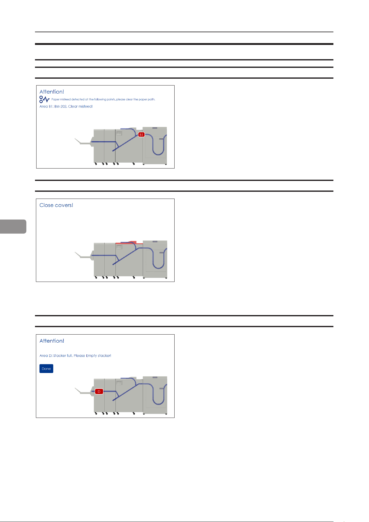
General fault codes
Clear Misfeed(s)
Close cover(s)
6
In general, fault codes indicate a misfeed
condition. When a misfeed occurs, a code,
the message “Clear misfeed(s)” and the
jam area will be displayed. See section
5, “Clearing Misfeeds”, for how to clear a
misfeed.
When the message “Close Cover(s)” is
displayed any of the interlock switches are
actuated.
1 Check that the top cover is in down
position.
Empty stacker!
2 Make sure that the cover of the Belt
Stacker is in normal position, see section
5, “Clearing Misfeeds”, Belt stacker.
3 Make sure power cables between
Booklet Maker, BookFold and Trimmer
are connected
This message will be displayed when
the stacker is full. Empty the belt stacker
and press the [Done] button to continue
operation.
78

7. REMARKS
Do’s And Don’ts
• Always follow all warnings marked on, or supplied with, the equipment.
• Always exercise care in moving or relocating the equipment.
• CAUTION
Unplug the power cord from the wall outlet and machine before you move or relocate
the equipment.
• Do not remove the covers or guards that are fastened with screws.
• Do not override or bypass electrical or mechanical interlock devices.
• Do not operate the equipment if you notice unusual noises or odors. Disconnect the
power cord from the power source and call your authorized technician to correct the
problem.
WARNING
Do not put ngers or other parts of the body between the upper and lower trimmer knives.
• Do not switch off the main power switch while machine is running. Make sure machine
cycle has ended.
• Do not open covers while machine is running.
• Do not move machine while machine is running.
79

Where to put Your Machine
Machine environment
• Always locate the equipment on a solid support surface with adequate strength for the
weight of the machine.
• Always keep magnets and all devices with strong magnetic elds away from the
machine.
If the place of installation is air-conditioned or heated, do not place the machine where it
will be:
• Subjected to sudden temperature changes.
• Directly exposed to cool air from air-conditioner.
• Directly exposed to heat from heater.
• Directly exposed to sunlight.
7
Power connection
• Always connect the equipment to a properly grounded power source. If in
doubt, have the power source checked by a qualied electrician.
• WARNING
Improper grounding of the equipment can result in electrical shock.
• Never connect the machine to a power source that lacks a ground connection
terminal.
80

Access to machine
Place the machine near the power source, providing clearance as shown.
550 mm
22”
90 mm
3.5”
105 mm
4”
400 mm
16”
420-630 mm
17-26”
660 mm
360 mm
14”
26”
360 mm
14”
850 mm
33.5”
2700-2910 mm
106.7-114.6”
750 mm
29.5”
700 mm
27.5”
530 mm
710 mm
28”
21”
860 mm
33.8”
1835 mm
72.2”
Ensure that the minimum required oor space is available for the system that you are
about to install (Figure 1).
The optional high capacity Belt Stacker BST4000-1 can be placed either in-line or angled
to the Booklet Making system. The BST4000-1 measures 1730x440 mm / 68x17”.
Approximate oor space requirements / conguration;
• BLM 35/50 + Stacker ~1480 mm / 58.2”.
• BLM 35/50 +FTR50 + Stacker ~ 1840 mm / 72.4”.
• BLM 35/50 + BF50 + FTR50 + Stacker ~ 2200 mm / 86.6”.
• RCT + BLM 35/50 + BF50 + FTR50 + Stacker = 2910 mm / 114.6”.
• RCT + BLM 35/50 + BF50 + FTR50 + BST4000-1 Stacker (straight) = 4430 mm / 174.4”.
• RCT + BLM 35/50 + BF50 + FTR50 + BST4000-1 Stacker (angled) = 3140 mm / 123.6”.
7
NOTE:
BLM 35/50 Upgrade kit and Cover Feeder Module does not impact oor space
requirements.
81

Maintaining Your Machines
Never attempt any maintenance functi on t hat is not speci cally described in this documentation.
Cover Feeder
Cleaning feed rollers and paper separator pad
The Feed rollers need to be cleaned regularly when in use, and if the unit has not been
used for a period of time. How often this should be done, depends on the paper type and
print quality.
An increasing number of misfeeds, or double feeds, is one indication of the need to clean
the Feed Rollers.
1
Remove the feed roller assembly by pressing it to the front of unit (A). The non
operator side end of the feed roller assembly will now be released (B) and the
assembly can be removed.
7
2
Clean the Feed rollers and the Paper separator pad with water and a clean lint free
cloth.
Press toward front.
Lift out this side
A
B
Paper separator pad
82
Feed rollers

BookFold Module
Cleaning feed belts
The feed belts need to be cleaned regularly when in use, and if the unit has not been used
for a period of time. How often this should be done, depends on the paper type and print
quality.
An increasing number of misfeeds is one indication of the need to clean the feed belts.
Clean the feed belts with water and a lint free cloth.
1
Open the top cover.
2
Clean the upper feed belts (A). The upper feed belts can easily be rotated in either
direction.
3
Press the release latch (B), one to each and lift up the upper feed belts to access the
lower feed belts.
4
Clean the lower feed belts (C). Rotate the lower feed belts towards the exit side for
complete cleaning.
5
Place the upper feed belts in normal position.
6
Close the top cover.
7
B
C
A
D
Upper non operator side feed belt lifted up.Upper feed belts in normal position.
NOTE:
The upper feed belt on the
operator side (D) cannot be
lifted fully.
83

BookFold Module, continued
Pressure springs
If feed errors occur, check that the pressure on the upper feed belts is set to the default
position. The pressure springs should always be at its upper position where the pressure is
equal to its highest value.
Non operator side spring in upper
position (default position)
7
operator side spring in lower position
Pressure Clamps:
Smearing marks from the pressure clamps may appear if the clamps are not clean. If
marks occur, run a number of blank booklets to clean the clamps prior to running your next
set of booklets.
84

RCT Module
The feed rollers and paper path need to be cleaned regularly when in use, and if the unit
has not been used for a period of time. How often this should be done depends on the paper
type and print quality.
An increasing number of misfeeds is one indication of the need to clean the feed roller, paper
path and/or the sensors. Feed rollers and paper path are cleaned with the same cleaning agent
used to clean the printer and a lint free cloth. Sensors are wiped clean with a lint free cloth.
A problem with registration accuracy is often related to build up residual toner and paper dust.
CAUTION
Never use any cleaning uids on sensors.
Cleaning the paper path transportation nip rollers (12x)
Also clean the idler rollers
WARNING
Do not put your ngers within knife protections.
Doing so may result in injury.
Knife protections
7
Nip rollers
85
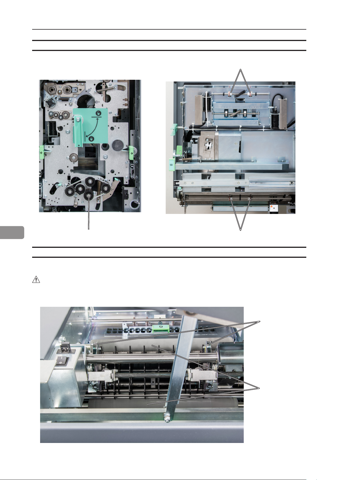
Cleaning the paper path transportation nip rollers (12x), continued
Nip rollers
7
Cleaning the xing rollers (3x)
Also clean the idling rollers
WARNING
Do not place your ngers inside the knife guards.
Doing so may result in injury.
Nip rollers (2x)
Nip rollers
Knife guards
Fixing rollers
86
continued on next
page

Cleaning the xing rollers (3x), continued
Fixing rollers
Cleaning the registration cross roller (4x) & friction tires (4X)
7
Registration cross rollers
Cleaning friction tires
87
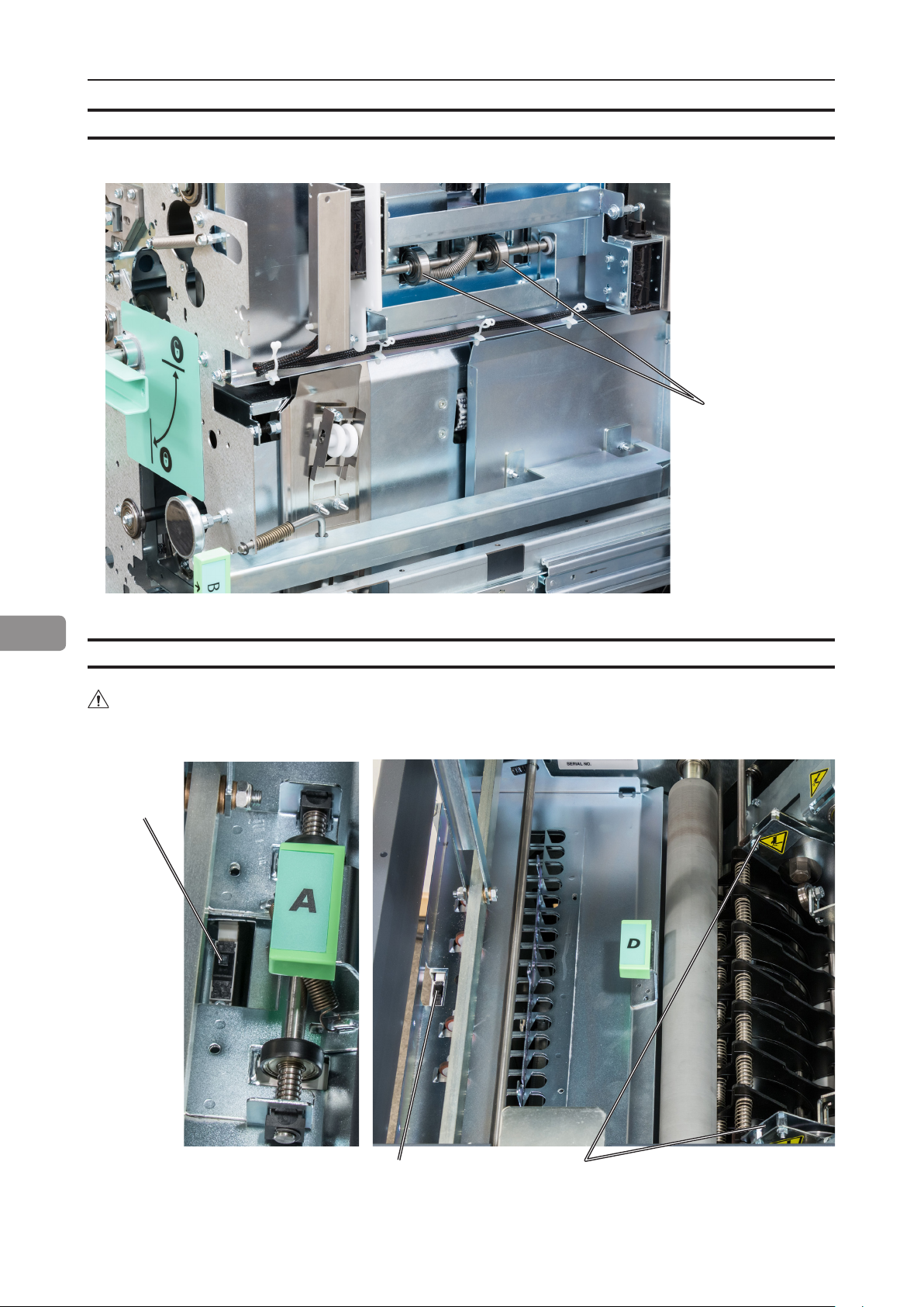
Cleaning the rotator rollers (2x)
Also clean the idler rollers
Rotator rollers
7
Cleaning the paper path sensors (5x)
WARNING
Do not place your ngers inside the knife guards.
Doing so may result in injury.
Infeed
sensor
88
Knife guardsExit sensor
continued on next page

Cleaning the paper path sensors (5x), continued
Rotator sensor
7
Registration sensor
89

Cleaning the paper path sensors (5x), continued
Creaser
sensor
7
Cleaning of creaser tools (2x)
After a period of time toner and paper dust may leave residuals in the grooves of the tool.
These grooves must be cleaned periodically to maintain creasing performance.
Grooves on both sides of the tool
90

Adjustment of Bleed Trimmer registration angle (parallel cut)
Adjustment of Bleed Trimmer registration angle (trimmer cut parallel to registration
(operator side) edge)
1
Turn adjustment screw [A] in desired direction. Change in adjustment is reected on
the reference scale [B].
Turn the adjustment
Process direction
screw clockwise to
remedy this misalignment
NOTE:
Sheets may show wrinkles in the process direction if adjustment is set too tight.
Turn adjustment screw counter clockwise until wrinkles disappear.
7
[A] [B]
91
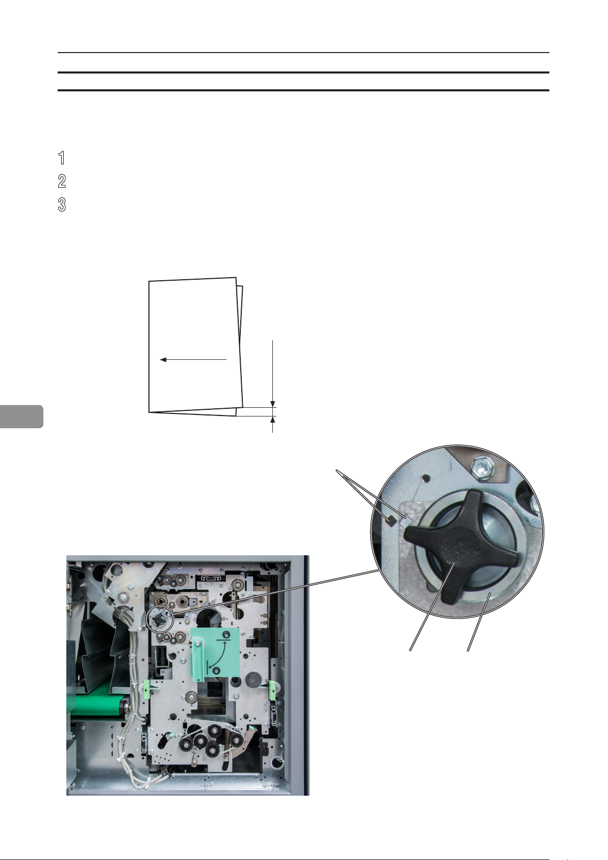
Adjustment of Creaser registration angle
Adjustment of Creaser registration angle
1
Loosen the star shaped knob [A].
2
Turn the knurled eccentric adjuster [B] to move reference mark in the desired direction.
3
Tighten the star shaped knob [A] again.
7
Process direction
Lower the operator side side of the
creaser to remedy
this misalignment
Reference marks
92
[A] [B]

Best practices for the BLM 35/50 system
• If the set is not properly registered (side jogged and back jogged), ne adjustment of registra-
tion may improve the situation. See section Fine-tuning booklet appearance for details.
• If staples have problems penetrating thicker sets of heavy media changing staple cartridge may
improve the situation.
• The BookFold Module may wrinkle the cover at the spine when light weight media is used for
cover sheet. Changing to heavier stock or turning BookFold Module off usually resolves the
problem.
• Staple back may be radius shaped (bent) when running with BookFold Module. Moving staple
position so staple is centered on the spine will reduce this phenomenon.
• Covers may show marking along the spine of the booklet from the clamp in the BookFold Mod-
ule. The more pages in the booklet, the more evident the marking.
• For jobs with multiple sheets of 200 gsm or heavier the BookFold Module is recommended for
an acceptable output. If a BookFold Module is present in the conguration, it should be turned
ON or feed problem at output may occur.
• If the Adjustment of “Bleed Trimmer registration angle” described in section Maintaining Your Ma-
chines in the OP manual is set too tight, the sheets may show wrinkles in the process direction.
• To prevent this phenomenon, turn the adjustment screw counter clockwise until the wrinkles
disappear.
• If a JOB is cancelled on the printer there might be an incomplete set inside the BLM 35/50
system. This set has to be manually removed from the system by opening and closing the top
cover of the Booklet Maker. This will purge the set.
7
93

Limitations of the BLM 35/50 system
• The BLM 35/50 Production Booklet Maker systems are suited for customers whose booklet
making needs will not exceed a yearly average of 30,000 booklets per month.
• If sheets entering the BLM 35/50 is not uniform and square the booklet quality will vary accordingly.
• The maximum recommended number of sheets that can be folded without stapling is 5 sheets of
80 gsm. If there is very low friction between the sheets, running non stapled sets may be difcult.
• Staple position may vary on the spine when being square formed with the BookFold Module,
especially on thicker booklets. Moving staple position so staple is centered on the spine will
reduce this phenomenon.
• Staple may be radius shaped (bent) when running with the BookFold Module. Moving staple
position so staple is centered on the spine will reduce this phenomenon.
• Covers may show marking along the spine of the booklet from the clamp in the BookFold Module. The more pages in the booklet, the more evident the marking.
• For some white coated stock, such as “Silk type” two sided coated paper, occasional fold roller marks
may be observed on the “top side” of the book.
• The double feed sensor should be turned off when feeding cover 200 gsm or more from the
Cover Feeder. You may also have to turn off this function if you have heavy dark area coverage
7
or covers with different images on them.
• For jobs with multiple sheets of 200 gsm or heavier, the BookFold Module is recommended for
an acceptable output. If a BookFold Module is present in the conguration it shall be turned ON
or feed problem at output may occur.
• Heavy weight media will show image crack in the spine, pre-crease the cover to avoid cracking.
• Thick books made from coated stock with high friction between each sheet may show permanent “wave like” deformation of the sheets.
• Marks from the fold knife may appear on sensitive media on the inner sheet.
• Marks from side guide motion may appear on sensitive media.
• Never run simplex printed sheets from the printer in-line.
• Covers may show markings from the Cover Feeder separation process.
• Avoid using smear sensitive material in Cover Feeder.
• Small booklets A5/ 5,5 x 8,5” or smaller may stack poorly on the conveyer.
• If corners/edges of sheets by any reason are folded before trimming,
result may look as illustrated when corners/edges are unfolded.
94

Limitations of the BLM 35/50 system, cont.
• Sheets may show marks from the “registration rollers” in the RCT module, as shown in the image below. These marks are more commonly seen on silk/coated paper and on darker images.
Changing media will improve the situation.
These marks have been seen consistently on the following media:
• Océ Top Coated Plus Silk
• Océ Top Coated Plus Gloss
• Océ Top Colour Zero
• Neenah Smooth
• On some coated media, staples may not completely penetrate the set resulting in a faulty
staple. If problem persists, consider changing media. Staple may not be able to penetrate the
number of sheets indicated by the “Set Size Guide”. Some uncoated extra “dense” paper may
show the same limitation. The following list shows examples of media where this has been
observed:
• Futura Laser Gloss 80c
• Hammermil Laser Print
• OPUS Gloss
• On brand new Booklet Maker units, paper may show trace of oil coming from the fold mechanism. Oil is applied to the mechanism during production. The problem will be eliminated after
initial production.
• When trimming small amount (less than 5mm or 0.2”) in the Trimmer Module on books made
from more than 2 sheets, the cut may not be clean, leaving trim waste hanging from the book.
7
• Paper can show markings on the lead edge of the set from the compiler area. If this occurs the
use of the Trimmer Module will eliminate this
• For thick booklets, the clinch quality of the staples may show limitations resulting in the staple
legs to be spaced away from the sheets.
• Heavy media above 250gsm/14lb Index may show feeding problems in the RCT Module. This
issue will be more common on smaller sheet sizes A4 and 8,5” x 11”
95

Limitations of the BLM 35/50 system, cont.
• Staple leg offset outside the 1,0mm specication can occur on thicker sets. To check if the unit
performs within specication produce a book made from 4 sheets of 80 gsm plain paper.
Max 1,0mm
• For thick books with a thin cover, the cover can be “pulled back” during the registration process
in the Face Trimmer. This can result in the cover sheet not being trimmed. Recommendation is
to use a heavier cover for thick books (over approx. 15 sheets).
• For some media, the legs of the staples may not be properly clinched causing the legs of the
staple to be spaced away from the inner sheet. This phenomenon occurs on extra thick books
over 40 sheets made from “soft” paper (recycled and some non-coated media mostly).
• The BookFold roller can pick up “colour” from the rst staple during the BookFold process.
After one full revolution of the BookFold roller, the colour is smeared off on the spine of the
booklet. This phenomenon occurs more for some coated media and for higher BookFold
modes.
7
• The “pressure foot” in the BookFold Module can cause a shiny mark on sensitive media. This
phenomenon has been observed on Glossy media.
• Thick booklets that are not square folded may have a higher tendency to be scratched.
• Sensitive media may pick up toner or residue while being transported through the paper path.
Cleaning the paper path and conducting some preventative maintenance may help improve the
situation.
96

8. Specication
Machine Specications
Rotate Crease Trim Module (option)
Specications Remarks
Speed Same as BLM35/50 Booklet Maker
Standard Paper Sizes Same as BLM35/50 Booklet Maker
Paper Size Minimum (Out) Same as BLM35/50 Booklet Maker
Paper Size Maximum (Out) Same as BLM35/50 Booklet Maker
Paper Width Maximum (In) 330mm 5mm bleed trim will auto-
matically be turned on
Paper Weight (Minimum) Same as BLM35/50 Booklet Maker
Paper Weight (Maximum) Same as BLM35/50 Booklet Maker Above 300gsm limited
performance with some
media
Rotator (optional)
Width (cross process direction)
Rotation is only possible within
the interval
Creaser
Tools
Fine tool
Coarse tool
Bleed Trimmer
Minimum bleed trimming
Maximum bleed trimming
Max asymmetric bleed trimming
Input / Output Sheets Same as BLM35/50 Booklet Maker
Input / Output Sheets Same as BLM35/50 Booklet Maker
min. 275mm. (10.9”).
Width (cross process direction)
max. 325mm. (12.7”).
Length (process direction)
min. 205mm. (8.1”).
Length (process direction)
max. 232mm. (9.1”).
Stock < 120 gsm
Stock > 120 gsm
(gsm =grams per sq. meter)
5 mm
30 mm
±5 mm
On each side of the sheet
Off-line Use Not possible
Weight 210kg/463lb
Dimensions (W x D x H) 710 x 860 x 1080 / 28 x 33.8 x 42.5”
(incl. 105mm / 4” waste transport)
Power Source 100 - 230V ±10% 50-60Hz
Power Consumption 300W Continuous operation
400W Max
97

Booklet Maker
Major Specications
Specications Remarks
Speed (Online usage) Maintains engine speed. Actual speed in number of book-
lets (per min / hour) depends on
number of sheets per booklet.
8
Standard Paper Sizes A4, SRA4, B4, A3, SRA3,
8.5x11”, 8.5x14”, 9x12”, 11x17”, 12x18”
Paper Size (Minimum) Width 206mm / 8.1”
Length 275mm / 10.8”
Paper Size (Maximum) Width 320mm / 12.6”
Length 457.2mm / 18”
Paper Weight (Minimum) 64gsm/16lb Bond uncoated
105gsm coated
Paper Weight (Maximum) 300gsm / 172lb Index / 115lb Cover 350gsm / 130lb Cover
Belt stacker capacity 2 sheets: 200 sets
8 sheets: 70 sets
15 sheets: 35 sets
20 sheets: 25 sets
30 sheets: 15 sets
35 sheets: 15 sets
40 sheets: 10 sets
45 sheets: 10 sets
50 sheets: 10 sets
Folding/stapling capability
Folding capability only 1 to 2 sheets
2 – 35 or 50 Sheets (80gsm / 20lb Bond) See Set Size Guide for more
Custom sizes are available
80gsm / 20lb Bond
Figures are based on rough
estimates and founded on pure
observation
information
Off-line use Possible Staple / Fold (2 staples)
Weight 155 kg / 341.7 lb
Dimensions (W x D x H) 1420 x 730 x 1050mm / 55.9 x 28.8 x 41.4” Incl. belt stacker*
Incl. cable protector**
Power Source 100 - 230V, 50-60Hz + 6%, - 10%
Power consumption 250 or less Continuous Operations
Noise emission 62dB Complete system
Plockmatic use open source code in parts of this product
*The Belt Stacker, installed after Booklet Maker, BookFold Module or Trimmer, adds 420 - 630mm / 16.5” -
24.8” to system length.
**Cable protector adds 50mm / 2” to depth.
98

Cover Feeder Module
Specications Remarks
Maximum Speed Same as BLM35/50 Booklet Maker A3/11x17” or bigger paper
sizes, need two sheet sets as
inlet at least
Standard Paper Sizes Same as BLM35/50 Booklet Maker
Paper Weight (Minimum) 64gsm / 16lb Bond
Paper Weight (Maximum) 250gsm / 67lb Bond
Cover Feeder Capacity 20mm (app. 200 sheets of 80gsm paper)
13/16” (app. 200 sheets of 20lb Bond paper)
Off-line Use Possible (Together with Booklet maker)
Weight 8kg / 17.6lb or less
Dimensions (W x D x H) 310 x 190 x 530mm / 12.2 x 7.5 x 20.9” The Cover Feeder dimensions
are included in the Booklet
Maker dimensions and will not
add anything more to the space.
Power Source From BLM35/50 Booklet Maker
Trimmer Module
Specications Remarks
Speed 1800 sets per hour
Standard Paper Sizes Same as BLM35/50 Booklet Maker Custom sizes are available
Default trim length 4.5mm / (11/64”) Adjustable in 0.5mm (0.004”) steps
Minimum trimming 1mm / (0.0394”)* Rec. min trim is 2,5mm (0.098”)
Maximum trimming 16mm (5/8”) per cut Possible to trim down to 105mm
(49/64”). Trim larger than 16mm (5/8”)
will cause trimmer to make multiple
cycles. This reduces system speed
in some applications. Multiple cuts
also affect lifetime.
Paper Weight (Min / Max) Same as BLM35/50 Booklet Maker
Paper Weight (Max) Same as BLM35/50 Booklet Maker
Input / Output Sheets Same as BLM35/50 Booklet Maker
Off-line Use Possible (Together with Booklet maker)
Weight 73kg / 160.8lb or less
8
Dimensions (W x D x H) 360 x 1100 x 730mm / 14.2 x 43.3 x 28.8” Incl. cable protector**
Power Source From BLM35/50 Booklet Maker
* When trimming SRA3 (450mm) Booklets minimum trimming is 5mm, when trimming 18” Booklets minimum trimming is 9mm / 0.35”.
**Cable protector adds 90mm / 3.5” to depth.
99

BookFold Module
Specications Remarks
Speed Same as BLM35/50 Booklet Maker Appr. 6 - 30 sheet booklet
(80gsm / 20lb Bond)
Standard Paper Sizes Same as BLM35/50 Booklet Maker Custom sizes are available
Paper Weight (Minimum) Same as BLM35/50 Booklet Maker
Paper Weight (Maximum) Same as BLM35/50 Booklet Maker
Input / Output Sheets Same as BLM35/50 Booklet Maker
Off-line Use Possible (Together with Booklet maker &
Trimmer)
Weight 53kg / 116.7lb
Dimensions (W x H x D) 360 x 1100 x 730mm / 14.2 x 43.3 x 28.8” Incl. cable protector*
Power Source From BLM35/50 Booklet Maker
*Cable protector adds 90mm / 3.5” to depth.
BST4000-1 Belt Stacker Module
8
Speed Variable
Overlap Adjustable
Capacity A4 / 8,3”x11,7” ....≥ 1,000
Side guides Adjustable 0-357mm / 14”
Weight 70kg/1541lb
Dimensions
Table height
Width
Length
Power Source 100 - 240V, 50-60Hz, 1A + 6%, - 10%
Power Consumption 70W or less
Specications Remarks
A3 / 11,7”x16,5” .....≥ 500
575 - 1000mm / 22.6” - 39.4”
440mm / 17”
1380mm / 54”
Booklet of 2 sheets 80gsm / 20lb Bond
Booklet of 2 sheets 80gsm / 20lb Bond
Input height = Table height + 60mm / 2.4”
+ Control unit
+ 350mm / 14” for end stacking tray
100
 Loading...